Uni Condens 6000F - bosch-industrial.com.au · The Uni Condens 6000F condensing boiler has been...
36
Installation instructions Floor standing condensing boiler Uni Condens 6000F 6 720 648 053-00.2T Output range 800 - 1200 kW 6 720 803 637 (2012/03) GB/AU
Transcript of Uni Condens 6000F - bosch-industrial.com.au · The Uni Condens 6000F condensing boiler has been...
Installation instructions
Floor standing condensing boiler
Uni Condens 6000F
6 72
0 64
8 05
3-00
.2T
Output range 800 - 1200 kW
6 72
0 80
3 63
7(2
012/
03)G
B/AU
2 | Contents
Uni Condens 6000F6 720 803 637 (2012/03)
Contents
1 Key to symbols and safety instructions . . . . . . . . . . . . . . . . . . . 31.1 Explanation of symbols . . . . . . . . . . . . . . . . . . . . . . . . . 31.2 Safety instructions . . . . . . . . . . . . . . . . . . . . . . . . . . . . . 3
2 About the boiler . . . . . . . . . . . . . . . . . . . . . . . . . . . . . . . . . . . . . . 42.1 Type overview . . . . . . . . . . . . . . . . . . . . . . . . . . . . . . . . 42.2 Correct use . . . . . . . . . . . . . . . . . . . . . . . . . . . . . . . . . . . 42.3 Safety equipment . . . . . . . . . . . . . . . . . . . . . . . . . . . . . . 42.4 CE Declaration of Conformity . . . . . . . . . . . . . . . . . . . . 42.5 Scope of supply . . . . . . . . . . . . . . . . . . . . . . . . . . . . . . . 42.5.1 Accessories supplied . . . . . . . . . . . . . . . . . . . . . . . . . . . 42.5.2 Required accessories . . . . . . . . . . . . . . . . . . . . . . . . . . 42.6 Operating conditions . . . . . . . . . . . . . . . . . . . . . . . . . . 42.7 Suitable fuels . . . . . . . . . . . . . . . . . . . . . . . . . . . . . . . . . 52.8 Data plate . . . . . . . . . . . . . . . . . . . . . . . . . . . . . . . . . . . . 52.9 Tools, materials and auxiliary equipment . . . . . . . . . . . 52.10 Product description . . . . . . . . . . . . . . . . . . . . . . . . . . . . 52.11 Dimensions and specification . . . . . . . . . . . . . . . . . . . . 72.11.1 Dimensions . . . . . . . . . . . . . . . . . . . . . . . . . . . . . . . . . . . 72.11.2 Technical Data . . . . . . . . . . . . . . . . . . . . . . . . . . . . . . . . 82.11.3 Values for calculating the flue gas . . . . . . . . . . . . . . . . . 9
3 Information on installation and operation . . . . . . . . . . . . . . . . 93.1 Standards, regulations and directives . . . . . . . . . . . . . 93.2 Duty to obtain a permit and provide notification . . . . . 93.3 Burner selection and settings . . . . . . . . . . . . . . . . . . . . 93.4 Installation requirements . . . . . . . . . . . . . . . . . . . . . . 103.5 Combustion air quality . . . . . . . . . . . . . . . . . . . . . . . . . 103.6 Heating water quality . . . . . . . . . . . . . . . . . . . . . . . . . . 103.7 Using of antifreeze . . . . . . . . . . . . . . . . . . . . . . . . . . . . 103.8 Control unit settings . . . . . . . . . . . . . . . . . . . . . . . . . . 103.9 Hydraulic connection to the heating system . . . . . . . 123.10 Setting the minimum and maximum pressure
limiters . . . . . . . . . . . . . . . . . . . . . . . . . . . . . . . . . . . . . 123.11 Pressure maintenance . . . . . . . . . . . . . . . . . . . . . . . . . 13
4 Transport . . . . . . . . . . . . . . . . . . . . . . . . . . . . . . . . . . . . . . . . . . . 134.1 Moving the boiler with a forklift truck,
pallet truck or heavy duty rollers . . . . . . . . . . . . . . . . 134.1.1 Lifting the boiler with a crane . . . . . . . . . . . . . . . . . . . 134.1.2 Moving the boiler with a forklift truck . . . . . . . . . . . . . 144.1.3 Moving the boiler with heavy duty rollers . . . . . . . . . . 144.1.4 Moving the boiler with pallet trucks . . . . . . . . . . . . . . 14
5 Installation . . . . . . . . . . . . . . . . . . . . . . . . . . . . . . . . . . . . . . . . . . 155.1 Siting the boiler . . . . . . . . . . . . . . . . . . . . . . . . . . . . . . 155.2 Fitting sound insulation strips . . . . . . . . . . . . . . . . . . . 165.3 Levelling the boiler . . . . . . . . . . . . . . . . . . . . . . . . . . . . 165.4 Flue gas and water connections for heating system . 165.4.1 General requirements of the flue system . . . . . . . . . . 165.4.2 Fitting a sealing collar . . . . . . . . . . . . . . . . . . . . . . . . . 175.4.3 Connecting the boiler to the pipework . . . . . . . . . . . . 175.4.4 Information on condensate neutralisation . . . . . . . . . 175.4.5 Filling the boiler and checking connections for leaks 185.5 Opening and closing the combustion chamber door . 185.5.1 Opening and closing the combustion chamber door . 185.5.2 Refitting the door hinges . . . . . . . . . . . . . . . . . . . . . . . 185.6 Fitting the burner (accessory) . . . . . . . . . . . . . . . . . . 195.6.1 Fitting the burner plate . . . . . . . . . . . . . . . . . . . . . . . . 195.6.2 Fitting the burner to the burner plate . . . . . . . . . . . . . 20
5.7 Fitting and removing the front cover . . . . . . . . . . . . . 215.8 Fitting the control unit (accessory) . . . . . . . . . . . . . . 215.8.1 Fitting the control unit support and cable conduit . . 215.8.2 Fitting the control unit . . . . . . . . . . . . . . . . . . . . . . . . . 215.8.3 Making the electrical connection . . . . . . . . . . . . . . . . 225.9 Fitting temperature sensors . . . . . . . . . . . . . . . . . . . . 235.10 Routing the burner cable . . . . . . . . . . . . . . . . . . . . . . . 23
6 Commissioning . . . . . . . . . . . . . . . . . . . . . . . . . . . . . . . . . . . . . . 246.1 Flushing the heating system . . . . . . . . . . . . . . . . . . . . 246.2 Filling the heating system . . . . . . . . . . . . . . . . . . . . . . 246.3 Preparing the heating system for operation . . . . . . . 246.4 Commissioning the control unit and burner . . . . . . . . 246.5 Setting control unit parameters . . . . . . . . . . . . . . . . . 256.6 Commissioning report . . . . . . . . . . . . . . . . . . . . . . . . . 25
7 Shutting down . . . . . . . . . . . . . . . . . . . . . . . . . . . . . . . . . . . . . . . 267.1 Shutting down the heating system . . . . . . . . . . . . . . . 267.2 Shutting down the heating system in an emergency . 26
8 Inspection and maintenance . . . . . . . . . . . . . . . . . . . . . . . . . . . 268.1 General notes . . . . . . . . . . . . . . . . . . . . . . . . . . . . . . . . 268.2 Preparing the boiler for inspection and maintenance 268.3 Cleaning the boiler . . . . . . . . . . . . . . . . . . . . . . . . . . . . 268.3.1 Preparing the boiler for cleaning with brushes . . . . . 268.3.2 Cleaning the boiler with cleaning brushes . . . . . . . . . 268.3.3 Cleaning the reversing chamber . . . . . . . . . . . . . . . . . 278.3.4 Replacing the flue gas collector gasket . . . . . . . . . . . 288.3.5 Fitting the covers to the flue gas collector and
reversing chamber . . . . . . . . . . . . . . . . . . . . . . . . . . . 288.3.6 Wet-cleaning the boiler . . . . . . . . . . . . . . . . . . . . . . . . 288.4 Checking and correcting the water pressure . . . . . . . 288.4.1 When should you check the water pressure in the
heating system? . . . . . . . . . . . . . . . . . . . . . . . . . . . . . 298.4.2 Sealed unvented systems . . . . . . . . . . . . . . . . . . . . . . 298.4.3 Installations with automatic pressurisation units . . . 298.5 Inspection and maintenance reports . . . . . . . . . . . . . 30
9 Correcting a burner fault . . . . . . . . . . . . . . . . . . . . . . . . . . . . . . 31
10 Environmental protection/disposal . . . . . . . . . . . . . . . . . . . . . 32
11 System examples . . . . . . . . . . . . . . . . . . . . . . . . . . . . . . . . . . . . 3211.1 Layout of the minimum equipment for technical safety
in accordance with EN 12828; operating temperature ≤ 105 °C; cut-out temperature (STB) ≤ 110 °C . . . . 32
Keyword index . . . . . . . . . . . . . . . . . . . . . . . . . . . . . . . . . . . . . . 33
Key to symbols and safety instructions | 3
6 720 803 637 (2012/03)Uni Condens 6000F
1 Key to symbols and safety instructions
1.1 Explanation of symbols
Warnings
Keywords indicate the seriousness of the hazard in terms of the consequences of not following the safety instructions.• NOTICE indicates that material damage may occur.• CAUTION indicates that minor to medium injury may occur.• WARNING indicates that serious injury may occur.• DANGER indicates possible risk to life.
Important information
Additional symbols
1.2 Safety instructions
Danger through failure to consider your own safety in an emergency such as a fireB Never put your life at risk. Your own safety is paramount.
If you smell gasB close the gas tap.B Open the windows.B Never operate electrical switches, including telephones, plugs or
doorbells.B Extinguish all naked flames.B No open fire. B Never smoke.B Never use lighters.B Warn all occupants in the building, but do not ring doorbells.B Leave the building and telephone your national gas emergency service
on 0800 111999 from an outside phone.
If you smell flue gasB Switch off the appliance.B Open windows and doors.B Notify an authorised contractor.
Electric shock hazardB Before carrying out any work on the heating system, disconnect the
heating system from the power supply across all poles. For example, press the emergency stop switch outside the boiler room. It is not enough to switch off at the boiler control unit.
B Safeguard the heating system against unintentional reconnection.B Observe the country-specific rules and regulations when making the
electrical connection, commissioning, servicing and carrying out maintenance.
Siting, conversionAn insufficient supply of air can result in dangerous escape of flue gas.
B Only have the boiler installed or modified by a competent person.B Never modifiy any boiler components in contact with exhaust gas.B With open flue appliances: Never cover or reduce the size of air vents
in doors, windows or walls. If draught-proof windows are fitted, ensure there is an adequate ventilation.
B Ensure that the boiler installation room remains free from the risk of frost.
B The heating system must be installed and operated in accordance with the current: Statutory Instrument Laws, Gas Safety Regulations, IEE Regulations, Building Regulations, Local Water By-Laws, Health & Safety document 635 (The Electricity at Work Regulations) and any other local requirements. Observe all European and local installation standards, building regulations and the latest edition of the wiring regulations. Chemically aggressive substances, can corrode the appliance and invalidate any warranty.
Thermal disinfectionB Risk of scalding!
Monitor any operation with temperatures in excess of 60 °C.
Inspection and maintenanceB Recommendation for customers: Arrange a maintenance and
service contract with an authorised contractor, covering an annual inspection and responsive maintenance.
B The user is responsible for the general and environmental safety of the heating system.
B Immediately correct all faults to prevent system damage!B Use only genuine spare parts from the manufacturer. Losses caused
by the use of spare parts and accessories not supplied by the manufacturer are excluded from the manufacturer's warranty.
Explosive and highly flammable materialB Never use or store highly flammable materials (paper, thinners, paints
etc.) near the boiler.
Combustion/room airB Keep the combustion/ambient air free of corrosive substances (e.g.
halogenated hydrocarbons that contain chlorine or fluorine compounds). This will help prevent corrosion.
B Keep the combustion air supply free of dust.
Instructing the customerB Instruct the customer about how the boiler works and is operated.B Inform customers that they must not carry out any modifications or
repairs.
DisposalB Dispose of packaging in an environmentally responsible manner.
Warnings in this document are framed and identified by a warning triangle which is printed on a grey background.
Electrical hazards are identified by a lightning symbol surrounded by a warning triangle.
Important information in cases where there is no risk of personal injury or material losses is identified by the symbol shown on the left. It is bordered by horizontal lines above and below the text.
Symbol MeaningB a step in an action sequence
a reference to a related part in the document or to other related documents
• a list entry– a list entry (second level)
Table 1
4 | About the boiler
Uni Condens 6000F6 720 803 637 (2012/03)
2 About the boiler
2.1 Type overview
2.2 Correct useThe Uni Condens 6000F condensing boiler has been designed for hot water heating systems in e.g. multiple dwelling units or for industrial purposes.
Any gas burner to EN 676 and EN 267 can be used if its operating range matches the boiler specification.
Only burners that have been tested and approved for electromagnetic compatibility (EMC) may be used.
CFB control units are used with these boilers.
For further details on correct use chapter 2.6, page 4, chapter 2.7, page 5 and chapter 3, page 9.
2.3 Safety equipmentTo ensure safe operation, the boilers must be equipped with the following safety equipment:• The level of safety equipment must comply with at least EN 12828. • Also observe country-specific regulations if these specify further
requirements.• Observe the maximum temperature high limit stat setting of 110 °C.
Equipment examples are included in the appendix, page 32. The components comprising the safety equipment are available as accessories.
2.4 CE Declaration of ConformityThe design and operation of this product conform to the applicable European directives and supplementary national requirements.
Conformity has been demonstrated. You can ask for a copy of the declaration of conformity. For this see the contact address at the back cover of these instructions.
2.5 Scope of supplyThe boiler is supplied with its full casing. The boiler front cover is supplied separately and has to be fitted.
B On delivery, check that all packaging is in perfect condition.B Check the delivery for completeness.
The standard delivery consists of:
• Boiler body with casing• Front cover
2.5.1 Accessories suppliedThe following accessories are included in the standard delivery and have to be fitted:
• Control unit retainer and cable conduit (delivered inside the combustion chamber)
• Sound insulation strip• Siphon (delivered inside the combustion chamber)• Insulating rings for blast tube (delivered inside the combustion
chamber)• Technical documentation
2.5.2 Required accessoriesThe following accessories are not part of the standard delivery but are required to operate the boiler:• Burner• Burner plate, drilled or undrilled• Valve manifold• Safety equipment• Cleaning brushes• Control unit
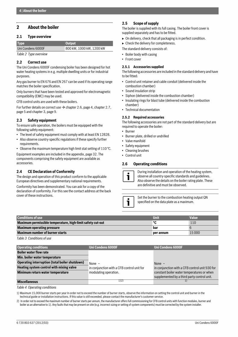
2.6 Operating conditions
Type OutputUni Condens 6000F 800 kW, 1000 kW, 1200 kW
Table 2 Type overview
During installation and operation of the heating system, observe all country-specific standards and guidelines.Also observe the details on the boiler rating plate. These are definitive and must be observed.
Set the burner to the combustion heating output QN specified on the data plate as a maximum.
Conditions of use Unit ValueMaximum permissible temperature, high-limit safety cut-out °C 110 Maximum operating pressure bar 6Maximum number of burner starts per annum 15 000
Table 3 Conditions of use
Operating conditions Uni Condens 6000F Uni Condens 6000FBoiler water flow rate
None – in conjunction with a CFB control unit for modulating operation.
None – in conjunction with a CFB control unit 930 for constant boiler water temperatures or when supplemented by a third party control unit.
Min. boiler water temperatureOperating interruption (total boiler shutdown)Heating system control with mixing valveMinimum return water temperature
Miscellaneous 1)2)
1) Maximum 15,000 burner starts per year In order not to exceed the number of burner starts, observe the information on setting the control unit and burner in the technical guide or installation instructions. If this value is still exceeded, please contact the manufacturer's customer service.
2) In order not to exceed the maximum number of burner starts per annum, the manufacturer offers full commissioning for CFB control units with function modules, burner and boiler as an alternative to 1). Any faults that may be present on site (e.g. incorrect sizing or setting of system components) must be corrected by the system installer.
1)
Table 4 Operating conditions
About the boiler | 5
6 720 803 637 (2012/03)Uni Condens 6000F
2.7 Suitable fuels
Permissible fuels• Natural gas from the public gas supply in accordance with national
regulations with a total sulphur content < 50 mg/m3.• LPG in accordance with national regulations with a content of
elementary sulphur < 1.5 ppm and volatile sulphur < 50 ppm.
The boiler must only be operated with the specified fuels. Only burners that are suitable for the specified fuels may be used.
Observe the manufacturer's burner selection list and the burner manufacturer's instructions.
2.8 Data plate
The data plate is fitted to the back of the boiler casing.
There you will find information such as the serial number, output and approval details.
2.9 Tools, materials and auxiliary equipmentFor the installation and maintenance of the boiler, standard tools are required, as used for heating, gas, water and electrical installations.
2.10 Product descriptionThe Uni Condens 6000F is a floor standing condensing boiler with a slim, compact design and a small footprint thanks to the combustion chamber being located at the top and the condensation heating surface being located at the bottom. In the following, it is referred to as the Uni Condens 6000F or the boiler.The Uni Condens 6000F has two thermohydraulically separated return connections for the high and low temperature circuits.For the type-tested boiler sizes with internal condensing heat exchanger and CE designation, the components that come into contact with hot gas and condensate are made of stainless steel.
Equip the Uni Condens 6000F with a suitable burner.
Optional accessories can be found in the general catalogue.
The following are the main components of the Uni Condens 6000F are ( Fig. 1, page 6):
• Boiler body [1] in conjunction with a burner The boiler block transfers the heat produced by the burner to the heating water.
• Thermally insulating casing The boiler jacket and thermal insulation reduce energy losses.
• Control unit [8] (accessory)The control unit monitors and controls all electrical boiler components.
The combustion of biogas is not permitted.
If you contact the manufacturer with any questions about this product, always provide the details on the data plate. These details enable us to assist you specifically and quickly.
NOTICE: System damage through the use of an incorrect burner.B Only use burners that meet the
technical requirements of the boiler ( chapter 2.11, page 7).
6 | About the boiler
Uni Condens 6000F6 720 803 637 (2012/03)
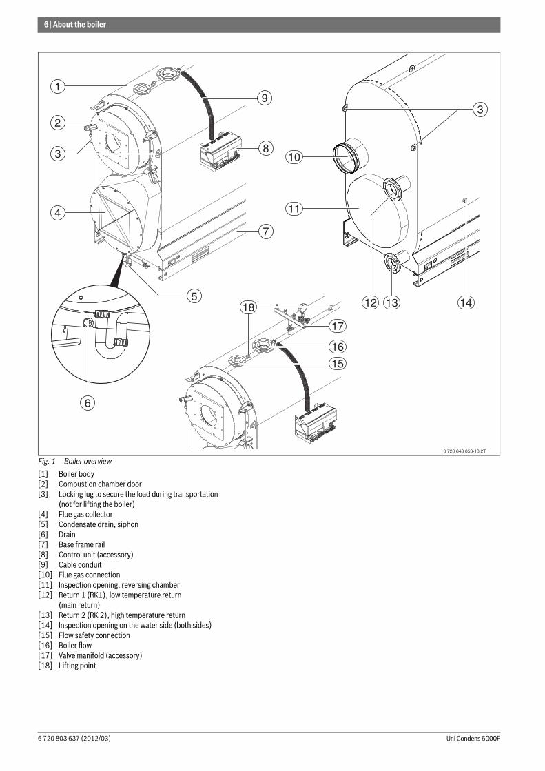
Fig. 1 Boiler overview
[1] Boiler body[2] Combustion chamber door[3] Locking lug to secure the load during transportation
(not for lifting the boiler)[4] Flue gas collector[5] Condensate drain, siphon[6] Drain[7] Base frame rail[8] Control unit (accessory)[9] Cable conduit[10] Flue gas connection[11] Inspection opening, reversing chamber[12] Return 1 (RK1), low temperature return
(main return)[13] Return 2 (RK 2), high temperature return[14] Inspection opening on the water side (both sides)[15] Flow safety connection[16] Boiler flow[17] Valve manifold (accessory)[18] Lifting point
6 720 648 053-13.2T
5
6
16
17
13 1412
11
10
3
4
2
1
3
7
8
9
18
15
About the boiler | 7
6 720 803 637 (2012/03)Uni Condens 6000F
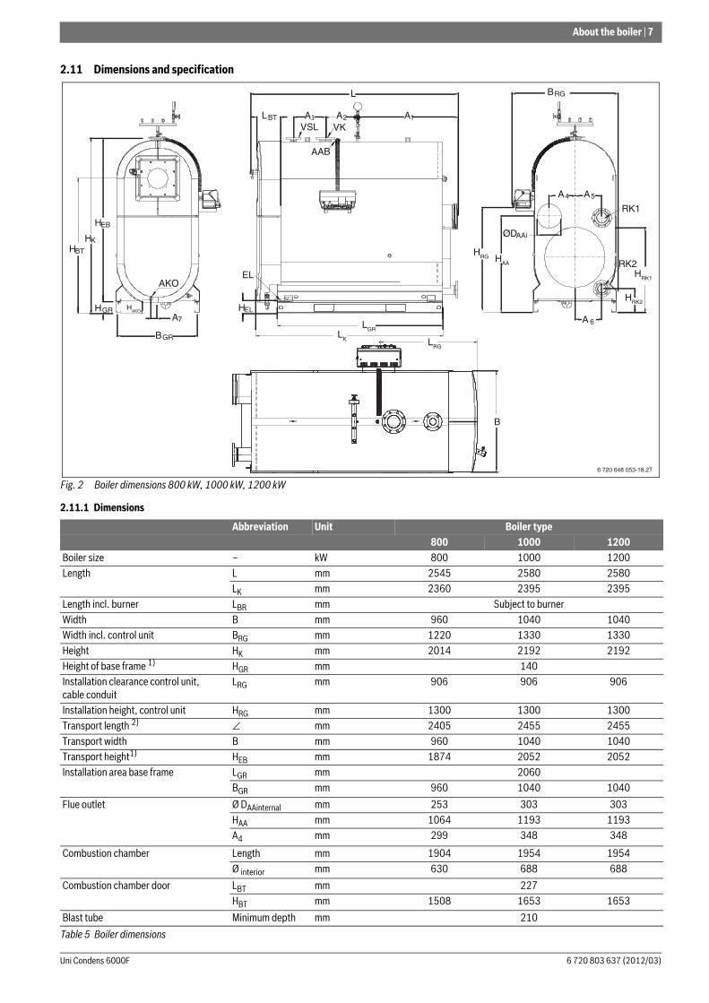
2.11 Dimensions and specification
Fig. 2 Boiler dimensions 800 kW, 1000 kW, 1200 kW
2.11.1 Dimensions
Abbreviation Unit Boiler type800 1000 1200
Boiler size – kW 800 1000 1200Length L mm 2545 2580 2580
LK mm 2360 2395 2395Length incl. burner LBR mm Subject to burnerWidth B mm 960 1040 1040Width incl. control unit BRG mm 1220 1330 1330Height HK mm 2014 2192 2192Height of base frame 1) HGR mm 140Installation clearance control unit, cable conduit
LRG mm 906 906 906
Installation height, control unit HRG mm 1300 1300 1300Transport length 2) ∠ mm 2405 2455 2455Transport width B mm 960 1040 1040Transport height1) HEB mm 1874 2052 2052Installation area base frame LGR mm 2060
BGR mm 960 1040 1040
Flue outlet Ø DAAinternal mm 253 303 303HAA mm 1064 1193 1193A4 mm 299 348 348
Combustion chamber Length mm 1904 1954 1954Ø interior mm 630 688 688
Combustion chamber door LBT mm 227HBT mm 1508 1653 1653
Blast tube Minimum depth mm 210
Table 5 Boiler dimensions
6 720 648 053-18.2T
BGR
HAKO
A7
HEB
HK
HGR
HBT
AKO
BRG
HAA
ØDAAi
A4 A5
A 6
RK1
RK2HRK1
HRG
HRK2
VSL VK
AAB
L
A12A3 LBT A
EL
HEL
LGRLK
B
LRG
8 | About the boiler
Uni Condens 6000F6 720 803 637 (2012/03)
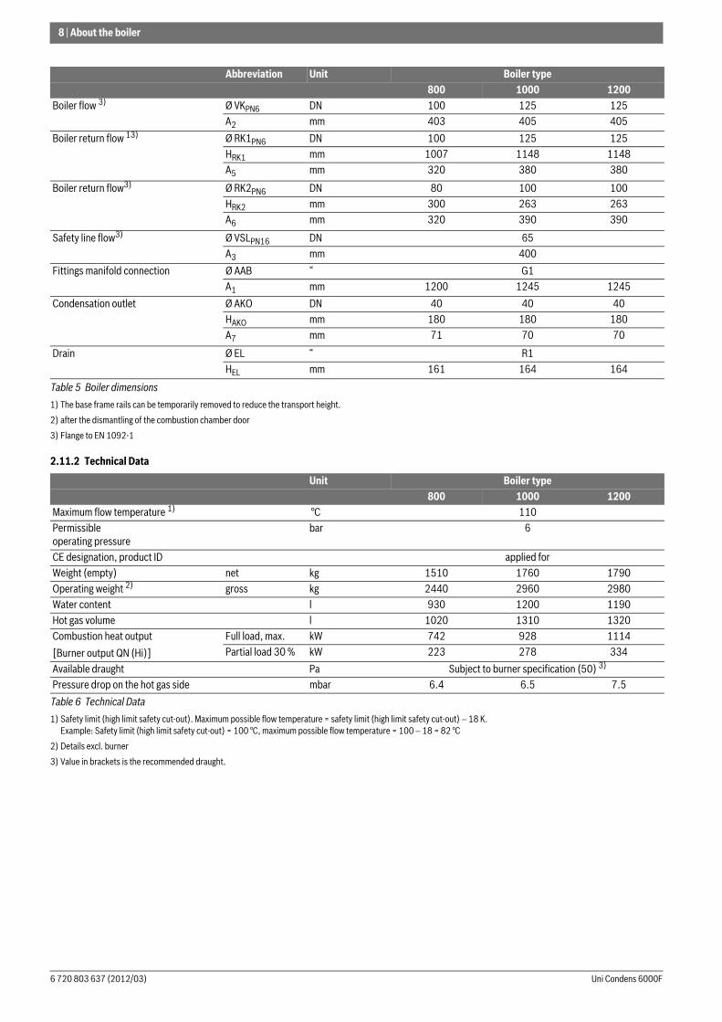
2.11.2 Technical Data
Boiler flow 3) Ø VKPN6 DN 100 125 125A2 mm 403 405 405
Boiler return flow 13) Ø RK1PN6 DN 100 125 125HRK1 mm 1007 1148 1148A5 mm 320 380 380
Boiler return flow3) Ø RK2PN6 DN 80 100 100HRK2 mm 300 263 263A6 mm 320 390 390
Safety line flow3) Ø VSLPN16 DN 65A3 mm 400
Fittings manifold connection Ø AAB “ G1A1 mm 1200 1245 1245
Condensation outlet Ø AKO DN 40 40 40HAKO mm 180 180 180A7 mm 71 70 70
Drain Ø EL “ R1HEL mm 161 164 164
1) The base frame rails can be temporarily removed to reduce the transport height.
2) after the dismantling of the combustion chamber door
3) Flange to EN 1092-1
Unit Boiler type800 1000 1200
Maximum flow temperature 1)
1) Safety limit (high limit safety cut-out). Maximum possible flow temperature = safety limit (high limit safety cut-out) − 18 K. Example: Safety limit (high limit safety cut-out) = 100 °C, maximum possible flow temperature = 100 − 18 = 82 °C
°C 110Permissible operating pressure
bar 6
CE designation, product ID applied forWeight (empty) net kg 1510 1760 1790Operating weight 2)
2) Details excl. burner
gross kg 2440 2960 2980Water content l 930 1200 1190Hot gas volume l 1020 1310 1320Combustion heat output
[Burner output QN (Hi)]
Full load, max. kW 742 928 1114Partial load 30 % kW 223 278 334
Available draught Pa Subject to burner specification (50) 3)
3) Value in brackets is the recommended draught.
Pressure drop on the hot gas side mbar 6.4 6.5 7.5
Table 6 Technical Data
Abbreviation Unit Boiler type800 1000 1200
Table 5 Boiler dimensions
Information on installation and operation | 9
6 720 803 637 (2012/03)Uni Condens 6000F
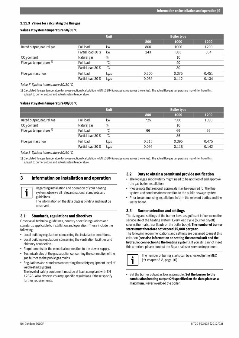
2.11.3 Values for calculating the flue gas
Values at system temperature 50/30 °C
Values at system temperature 80/60 °C
3 Information on installation and operation
3.1 Standards, regulations and directivesObserve all technical guidelines, country-specific regulations and standards applicable to installation and operation. These include the following:• Local building regulations concerning the installation conditions.• Local building regulations concerning the ventilation facilities and
chimney connection.• Requirements for the electrical connection to the power supply.• Technical rules of the gas supplier concerning the connection of the
gas burner to the public gas mains• Regulations and standards concerning the safety equipment level of
wet heating systems.The level of safety equipment must be at least compliant with EN 12828. Also observe country-specific regulations if these specify further requirements.
3.2 Duty to obtain a permit and provide notification• The local gas supply utility might need to be notified of and approve
the gas boiler installation• Please note that regional approvals may be required for the flue
system and condensate connection to the public sewage system• Prior to commencing installation, inform the relevant bodies and the
water board.
3.3 Burner selection and settingsThe sizing and settings of the burner have a significant influence on the service life of the heating system. Every load cycle (burner on/off) causes thermal stress (loads on the boiler body). The number of burner starts must therefore not exceed 15,000 per year.The following recommendations and settings are designed to meet this criterion (see also information on setting the control unit and the hydraulic connection to the heating system). If you still cannot meet this criterion, please contact the Bosch sales or service department.
• Set the burner output as low as possible. Set the burner to the combustion heating output QN specified on the data plate as a maximum. Never overload the boiler.
Unit Boiler type800 1000 1200
Rated output, natural gas Full load kW 800 1000 1200Partial load 30 % kW 243 303 364
CO2 content Natural gas % 10Flue gas temperature 1)
1) Calculated flue gas temperature for cross-sectional calculation to EN 13384 (average value across the series). The actual flue gas temperature may differ from this, subject to burner setting and actual system temperature.
Full load °C 40Partial load 30 % °C 30
Flue gas mass flow Full load kg/s 0.300 0.375 0.451Partial load 30 % kg/s 0.089 0.112 0.134
Table 7 System temperature 50/30 °C
Unit Boiler type800 1000 1200
Rated output, natural gas Full load kW 725 906 1090CO2 content Natural gas % 10Flue gas temperature 1)
1) Calculated flue gas temperature for cross-sectional calculation to EN 13384 (average value across the series). The actual flue gas temperature may differ from this, subject to burner setting and actual system temperature.
Full load °C 66 66 66Partial load 30 % °C 36
Flue gas mass flow Full load kg/s 0.316 0.395 0.475Partial load 30 % kg/s 0.095 0.118 0.142
Table 8 System temperature 80/60 °C
Regarding installation and operation of your heating system, observe all relevant national standards and guidelines. The information on the data plate is binding and must be observed.
The number of burner starts can be checked in the MEC ( chapter 3.8, page 10).
10 | Information on installation and operation
Uni Condens 6000F6 720 803 637 (2012/03)
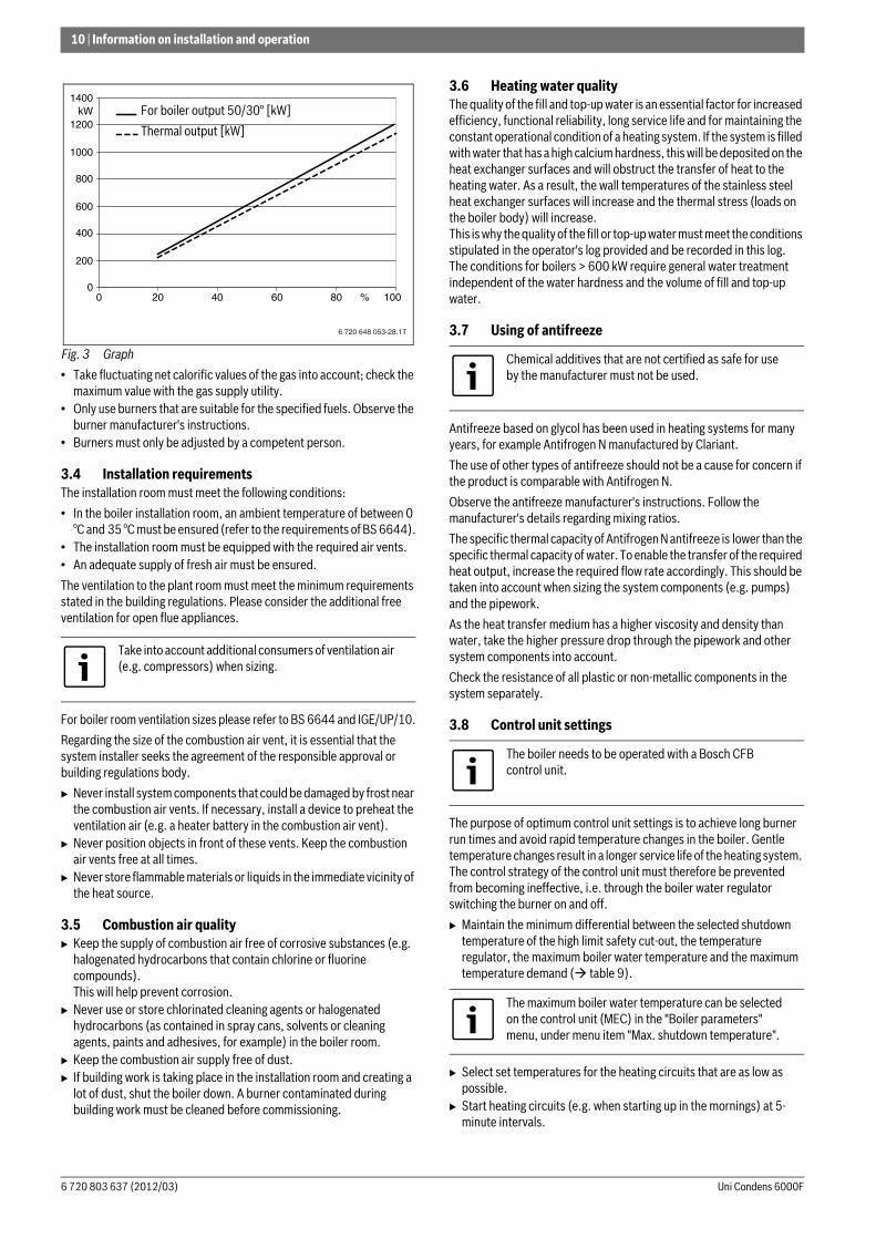
Fig. 3 Graph
• Take fluctuating net calorific values of the gas into account; check the maximum value with the gas supply utility.
• Only use burners that are suitable for the specified fuels. Observe the burner manufacturer's instructions.
• Burners must only be adjusted by a competent person.
3.4 Installation requirementsThe installation room must meet the following conditions:
• In the boiler installation room, an ambient temperature of between 0 °C and 35 °C must be ensured (refer to the requirements of BS 6644).
• The installation room must be equipped with the required air vents.• An adequate supply of fresh air must be ensured.
The ventilation to the plant room must meet the minimum requirements stated in the building regulations. Please consider the additional free ventilation for open flue appliances.
For boiler room ventilation sizes please refer to BS 6644 and IGE/UP/10.
Regarding the size of the combustion air vent, it is essential that the system installer seeks the agreement of the responsible approval or building regulations body.
B Never install system components that could be damaged by frost near the combustion air vents. If necessary, install a device to preheat the ventilation air (e.g. a heater battery in the combustion air vent).
B Never position objects in front of these vents. Keep the combustion air vents free at all times.
B Never store flammable materials or liquids in the immediate vicinity of the heat source.
3.5 Combustion air qualityB Keep the supply of combustion air free of corrosive substances (e.g.
halogenated hydrocarbons that contain chlorine or fluorine compounds). This will help prevent corrosion.
B Never use or store chlorinated cleaning agents or halogenated hydrocarbons (as contained in spray cans, solvents or cleaning agents, paints and adhesives, for example) in the boiler room.
B Keep the combustion air supply free of dust.B If building work is taking place in the installation room and creating a
lot of dust, shut the boiler down. A burner contaminated during building work must be cleaned before commissioning.
3.6 Heating water qualityThe quality of the fill and top-up water is an essential factor for increased efficiency, functional reliability, long service life and for maintaining the constant operational condition of a heating system. If the system is filled with water that has a high calcium hardness, this will be deposited on the heat exchanger surfaces and will obstruct the transfer of heat to the heating water. As a result, the wall temperatures of the stainless steel heat exchanger surfaces will increase and the thermal stress (loads on the boiler body) will increase.This is why the quality of the fill or top-up water must meet the conditions stipulated in the operator's log provided and be recorded in this log.The conditions for boilers > 600 kW require general water treatment independent of the water hardness and the volume of fill and top-up water.
3.7 Using of antifreeze
Antifreeze based on glycol has been used in heating systems for many years, for example Antifrogen N manufactured by Clariant.
The use of other types of antifreeze should not be a cause for concern if the product is comparable with Antifrogen N.
Observe the antifreeze manufacturer's instructions. Follow the manufacturer's details regarding mixing ratios.
The specific thermal capacity of Antifrogen N antifreeze is lower than the specific thermal capacity of water. To enable the transfer of the required heat output, increase the required flow rate accordingly. This should be taken into account when sizing the system components (e.g. pumps) and the pipework.
As the heat transfer medium has a higher viscosity and density than water, take the higher pressure drop through the pipework and other system components into account.
Check the resistance of all plastic or non-metallic components in the system separately.
3.8 Control unit settings
The purpose of optimum control unit settings is to achieve long burner run times and avoid rapid temperature changes in the boiler. Gentle temperature changes result in a longer service life of the heating system. The control strategy of the control unit must therefore be prevented from becoming ineffective, i.e. through the boiler water regulator switching the burner on and off.
B Maintain the minimum differential between the selected shutdown temperature of the high limit safety cut-out, the temperature regulator, the maximum boiler water temperature and the maximum temperature demand ( table 9).
B Select set temperatures for the heating circuits that are as low as possible.
B Start heating circuits (e.g. when starting up in the mornings) at 5-minute intervals.
Take into account additional consumers of ventilation air (e.g. compressors) when sizing.
6 720 648 053-28.1T
1400
1200kW
1000
800
600
400
200
200 40 60 80 % 1000
Kesselleistung bei 50/30° [kW]
Feuerungswärmeleistung [kW]
For boiler output 50/30° [kW]
Thermal output [kW]
Chemical additives that are not certified as safe for use by the manufacturer must not be used.
The boiler needs to be operated with a Bosch CFB control unit.
The maximum boiler water temperature can be selected on the control unit (MEC) in the "Boiler parameters" menu, under menu item "Max. shutdown temperature".
Information on installation and operation | 11
6 720 803 637 (2012/03)Uni Condens 6000F
Settings for boiler water regulator and maximum boiler water temperatureThe boiler water regulator is only designed to allow emergency operation with an adjustable boiler water temperature if the control electronics
fail. In standard control mode, the function of the boiler water regulator is provided by the maximum boiler water temperature. The maximum boiler water temperature can be selected in the control unit in the "Boiler parameters" menu, under menu item "Max. shutdown temperature".
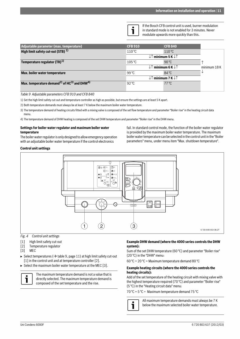
Control unit settings
Fig. 4 Control unit settings
[1] High limit safety cut-out[2] Temperature regulator[3] MEC
B Select temperatures ( table 9, page 11) at high limit safety cut-out [1] in the control unit and at temperature controller [2].
B Select the maximum boiler water temperature at the MEC [3].
Example DHW demand (where the 4000 series controls the DHW system):Sum of the set DHW temperature (60 °C) and parameter "Boiler rise" (20 °C) in the "DHW" menu:
60 °C + 20 °C = Maximum temperature demand 80 °C
Example heating circuits (where the 4000 series controls the heating circuits):Add of the set temperature of the heating circuit with mixing valve with the highest temperature required (70 °C) and parameter "Boiler rise" (5 °C) in the "Heating circuit data" menu:
70 °C + 5 °C = Maximum temperature demand 75 °C
If the Bosch CFB control unit is used, burner modulation in standard mode is not enabled for 3 minutes. Never modulate upwards more quickly than this.
Adjustable parameter (max. temperature) CFB 910 CFB 840High limit safety cut-out (STB) 1)
1) Set the high limit safety cut-out and temperature controller as high as possible, but ensure the settings are at least 5 K apart.
110 °C 110 °C
↑minimum 18 K↓
↓↑ minimum 5 K ↓↑Temperature regulator (TR)1) 105 °C 90 °C
↓↑ minimum 6 K ↓↑Max. boiler water temperature 99 °C 84 °C
↓↑ minimum 7 K ↓↑Max. temperature demand2) of HC3) and DHW4)
2) Both temperature demands must always be at least 7 K below the maximum boiler water temperature.
3) The temperature demand of heating circuits fitted with a mixing valve is composed of the set flow temperature and parameter "Boiler rise" in the heating circuit data menu.
4) The temperature demand of DHW heating is composed of the set DHW temperature and parameter "Boiler rise" in the DHW menu.
92 °C 77 °C
Table 9 Adjustable parameters CFB 910 and CFB 840
6 720 648 053-38.2T1 2 3
80
The maximum temperature demand is not a value that is directly selected. The maximum temperature demand is composed of the set temperature and the rise.
All maximum temperature demands must always be 7 K below the maximum selected boiler water temperature.
12 | Information on installation and operation
Uni Condens 6000F6 720 803 637 (2012/03)
Notes on setting third party control units
• The third party control unit (building management system or PLC controllers) must ensure a maximum internal boiler water temperature that is sufficiently different from the high limit safety cut-out. It must also be ensured that the digital burner controller rather than the boiler water temperature regulator switch the burner on and off.
• The control unit must ensure that the burner is switched to low load before being shut down. If this is not observed, the safety shut-off valve (SAV) in the gas train may lock out.
• Select control equipment that allows a gentle start-up with a time delay when the system is cold.
• After the burner demand, an automatic timer (for example) should limit the burner to low load for a period of approx. 180 seconds. This restricted heat demand will prevent uncontrolled starting and stopping of the burner.
• It must be possible to show the number of burner starts on the control unit used.
3.9 Hydraulic connection to the heating systemB If the system temperatures are different, use both return connectors
RK1 (top) and RK2 (bottom).B Connect heating circuits with high return temperatures to connector
RK2, and heating circuits with low return temperatures to connector RK1.
B Restrict the water flow rate in the boiler to a temperature difference of at least 7 K between flow and return.
B Size the pumps correctly.
B Before connecting the boiler, flush sludge and dirt out of the heating system.
B Ensure that no oxygen enters the heating water during operation.B Only operate the boiler in sealed unvented systems.
If the boiler is nonetheless used in an open vented heating system, additional measures are required to protect against corrosion and prevent sludge entering the boiler. The technical safety devices also require to be matched (equipment and settings).
B Consult the Bosch sales or service department.
Information on boiler cascades:B Select the boiler circuit pumps (flow rate) in accordance with the set
boiler output.B In the case of parallel switching of the boilers, maintain the same
temperature difference across all boilers.
3.10 Setting the minimum and maximum pressure limiters
Maximum pressure limiterThe maximum pressure limiter (not part of the standard delivery) must be set in such a way that the safety valve is prevented from discharging. To achieve this, a safety differential of 0.5 bar must be maintained to the release pressure of the safety valve. The maximum release pressure of the safety valve for the Uni Condens 6000F is 6 bar.
Example:
Safety valve pressure: PSV = 5 bar
Setting value, maximum pressure limiter: 5 bar − 0.5 bar = 4.5 bar
Minimum pressure limiterThe minimum pressure limiter (not part of the standard delivery) must be set in such a way that no steam bubbles form in the boiler, and that the boiler operates safely. This setting depends on the system conditions and the siting situation of the boiler system. For the setting value, the boiling pressure associated with the setting value of the high limit safety cut-out is relevant (high limit safety cut-out 110 °C equals 0.5 bar), as is the consumer at the highest geodetic level above the boiler.
Example:
Boiler system with high limit safety cut-out setting = 110 °C
Highest consumer above the boiler = 12 m (10 m equates to approx. 1 bar) 1.2 bar
Safety differential = 0.2 bar (fixed value)
Response pressure Pmin = 0.5 bar + 1.2 bar + 0.2 bar = 1.9 bar
NOTICE: System damage due to incorrect sensor position!The sensors of the safety cut-out (STB) and of the thermostat (TR) must be fitted at the installation site ( picture 23, [1], page 22) on the top of the boiler.
B In the case of third party control units, match the sensor immersion sleeve to the diameter of the sensors used.
B Do not change the length of the immersion sleeve.
Observe the operating conditions in chapter 2.6, page 4.Observe chapter 5.9, page 23 when installing sensors.
Unit ValueTemperature control unit s 40Monitor/limiter s 40Minimum difference between burner on and off temperatures
K 7
Table 10 Conditions of use
For an optimum energy yield, we recommend supplying a flow rate of > 10 % of the total nominal flow rate via connector RK1, with a return temperature below the dew point.
If there are no varying return temperatures, only return connector RK1 needs to be connected.
Restriction of the temperature difference is not necessary if the system is equipped with a dirt trap device.
High flow rates and oversized pumps can result in the accumulation of sludge or deposits on the heat exchanger surfaces.
The setting for the maximum pressure limiter can be found in the documentation provided with the pressure limiter.
The setting for the minimum pressure limiter can be found in the documentation provided with the pressure limiter.
Transport | 13
6 720 803 637 (2012/03)Uni Condens 6000F
3.11 Pressure maintenanceB Size the expansion vessels correctly.B Set the pre-charge pressures correctly.
If using pump-controlled pressurisation units, pressure fluctuations will occur. They can occur very frequently depending on the design of the system and the appliance settings. Even if these pressure fluctuations are small, if they occur very frequently they may cause considerable damage to the boiler, as it is designed for a predominantly static pressure load.To protection against damage:
B Ensure that every heat source is equipped with a separate expansion vessel.
B Set the pre-charge pressure of the expansion vessel correctly.
Recommended minimum volume of the expansion vessels if using pump-controlled pressurisation units:
4 Transport
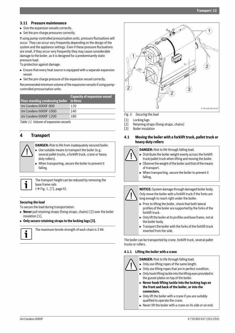
Securing the loadTo secure the load during transportation:B Never pull retaining straps (fixing straps, chains) [2] over the boiler
insulation [1].B Only secure retaining straps to the locking lugs [3].
Fig. 5 Securing the load
[1] Locking lugs[2] Retaining straps (fixing straps, chains)[3] Boiler insulation
4.1 Moving the boiler with a forklift truck, pallet truck or heavy duty rollers
The boiler can be transported by crane, forklift truck, several pallet trucks or rollers.
4.1.1 Lifting the boiler with a crane
Floor standing condensing boilerCapacity of expansion vessel in litres
Uni Condens 6000F-800 120Uni Condens 6000F-1000 140Uni Condens 6000F-1200 180
Table 11 Volume of expansion vessels
DANGER: Risk to life from inadequately secured boiler.B Use suitable means to transport the boiler (e.g.
several pallet trucks, a forklift truck, crane or heavy duty rollers).
B When transporting, secure the boiler to prevent it falling.
The transport height can be reduced by removing the base frame rails ( Fig. 1, [7], page 6).
The maximum tensile strength of each chain is 2 kN.
DANGER: Risk to life through falling load.B Distribute the boiler weight evenly across the forklift
truck/pallet truck when lifting and moving the boiler.B Observe the weight of the boiler and that of the means
of transport.B When transporting, secure the boiler to prevent it
falling.
NOTICE: System damage through damaged boiler body.Only move the boiler with a forklift truck if the forks are long enough to reach right under the boiler.
B Prior to lifting the boiler, check that both lateral profiles of the boiler are supported by the forks of the forklift truck.
B Only lift the boiler at its profiles and base frame, not at the boiler body.
B Transport the boiler with the forks of the forklift truck inserted from the side.
DANGER: Risk to life through falling load.B Only use lifting ropes of the same length.B Only use lifting ropes that are in perfect condition.B Only hook lifting tackle into the lifting eyes provided in
the gusset plates on top of the boiler.B Never hook lifting tackle into the locking lugs on
the front and back of the boiler, or into the connectors.
B Only lift the boiler with a crane if you are suitably qualified to operate the crane.
B Never lift the boiler with a crane on its side or on end.
6 720 648 053-39.2T
3
1
2
2
2
25°
1
14 | Transport
Uni Condens 6000F6 720 803 637 (2012/03)
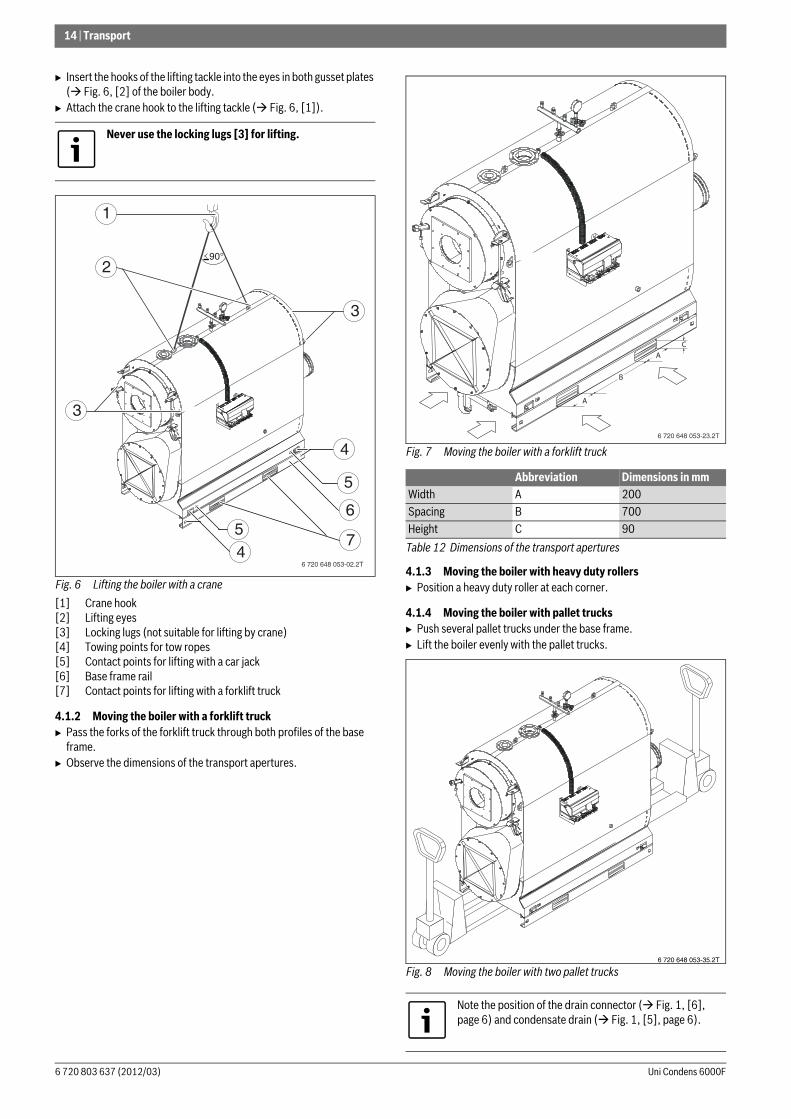
B Insert the hooks of the lifting tackle into the eyes in both gusset plates ( Fig. 6, [2] of the boiler body.
B Attach the crane hook to the lifting tackle ( Fig. 6, [1]).
Fig. 6 Lifting the boiler with a crane
[1] Crane hook[2] Lifting eyes[3] Locking lugs (not suitable for lifting by crane)[4] Towing points for tow ropes[5] Contact points for lifting with a car jack[6] Base frame rail[7] Contact points for lifting with a forklift truck
4.1.2 Moving the boiler with a forklift truckB Pass the forks of the forklift truck through both profiles of the base
frame.B Observe the dimensions of the transport apertures.
Fig. 7 Moving the boiler with a forklift truck
4.1.3 Moving the boiler with heavy duty rollersB Position a heavy duty roller at each corner.
4.1.4 Moving the boiler with pallet trucksB Push several pallet trucks under the base frame.B Lift the boiler evenly with the pallet trucks.
Fig. 8 Moving the boiler with two pallet trucks
Never use the locking lugs [3] for lifting.
1
2
3
3
4
5
56
74
90°
6 720 648 053-02.2T
Abbreviation Dimensions in mmWidth A 200Spacing B 700Height C 90
Table 12 Dimensions of the transport apertures
Note the position of the drain connector ( Fig. 1, [6], page 6) and condensate drain ( Fig. 1, [5], page 6).
6 720 648 053-23.2T
A
A
B
C
6 720 648 053-35.2T
Installation | 15
6 720 803 637 (2012/03)Uni Condens 6000F
5 Installation
5.1 Siting the boiler
Installation room requirements:• The support surface must provide sufficient load-bearing capacity
and solidity.• The installation room must be dry and free from the risk of frost.• The size of the installation room must be adequate to ensure correct
operation.
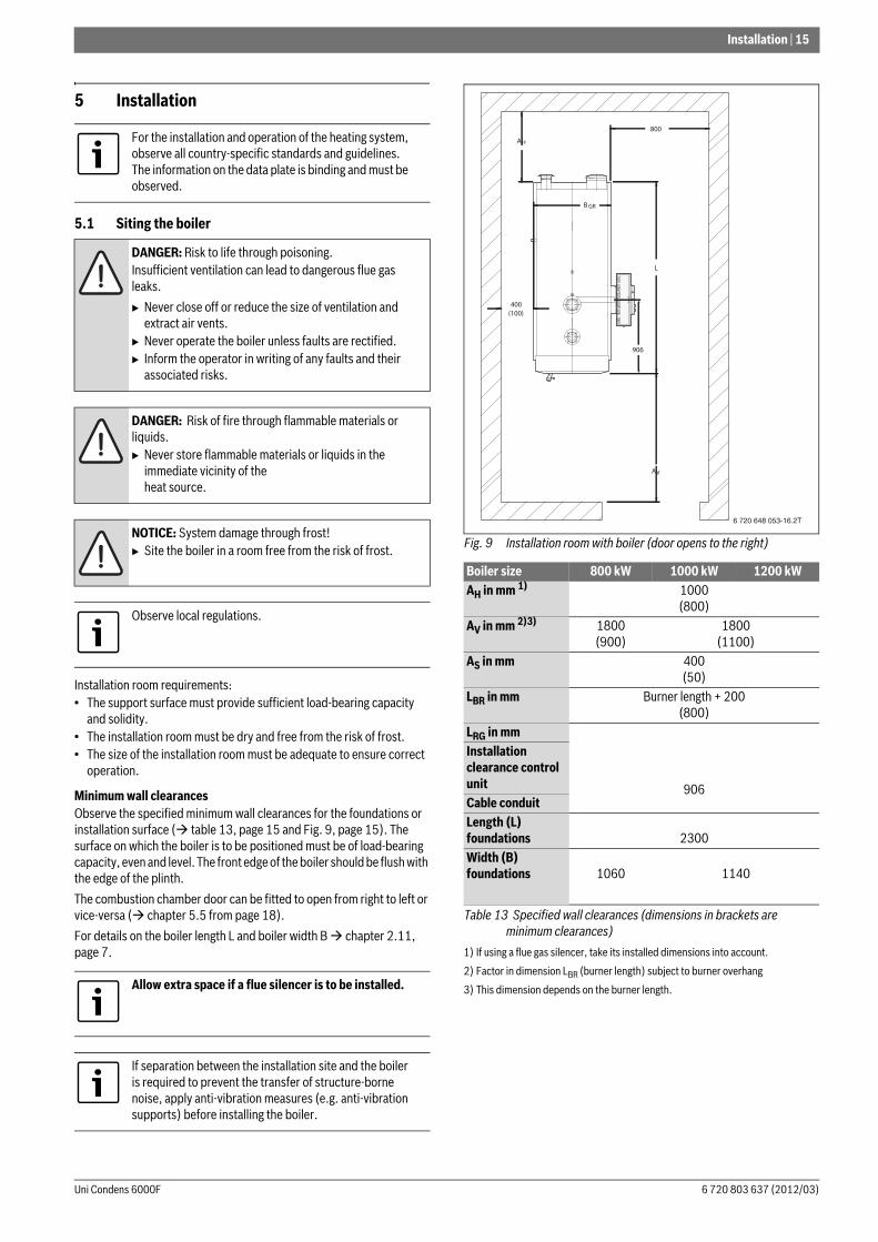
Minimum wall clearancesObserve the specified minimum wall clearances for the foundations or installation surface ( table 13, page 15 and Fig. 9, page 15). The surface on which the boiler is to be positioned must be of load-bearing capacity, even and level. The front edge of the boiler should be flush with the edge of the plinth.
The combustion chamber door can be fitted to open from right to left or vice-versa ( chapter 5.5 from page 18).
For details on the boiler length L and boiler width B chapter 2.11, page 7.
Fig. 9 Installation room with boiler (door opens to the right)
For the installation and operation of the heating system, observe all country-specific standards and guidelines. The information on the data plate is binding and must be observed.
DANGER: Risk to life through poisoning.Insufficient ventilation can lead to dangerous flue gas leaks.
B Never close off or reduce the size of ventilation and extract air vents.
B Never operate the boiler unless faults are rectified. B Inform the operator in writing of any faults and their
associated risks.
DANGER: Risk of fire through flammable materials or liquids.B Never store flammable materials or liquids in the
immediate vicinity of the heat source.
NOTICE: System damage through frost!B Site the boiler in a room free from the risk of frost.
Observe local regulations.
Allow extra space if a flue silencer is to be installed.
If separation between the installation site and the boiler is required to prevent the transfer of structure-borne noise, apply anti-vibration measures (e.g. anti-vibration supports) before installing the boiler.
Boiler size 800 kW 1000 kW 1200 kWAH in mm 1)
1) If using a flue gas silencer, take its installed dimensions into account.
1000(800)
AV in mm 2)3)
2) Factor in dimension LBR (burner length) subject to burner overhang
3) This dimension depends on the burner length.
1800(900)
1800(1100)
AS in mm 400(50)
LBR in mm Burner length + 200 (800)
LRG in mm
906
Installation clearance control unitCable conduitLength (L) foundations 2300Width (B) foundations 1060 1140
Table 13 Specified wall clearances (dimensions in brackets are minimum clearances)
B GR
800
L
AV
AH
400(100)
906
6 720 648 053-16.2T
16 | Installation
Uni Condens 6000F6 720 803 637 (2012/03)
5.2 Fitting sound insulation strips
To reduce the noise, place the sound insulation strips (supplied with the boiler) below the base frame, flush with the front and back of the boiler.
B Position the boiler at its installation site.B Place sound insulation strips lengthways below the boiler frame at all
four corners.B Carefully set the boiler down.
Fig. 10 Positioning the sound insulation strips
[1] Sound insulation strips
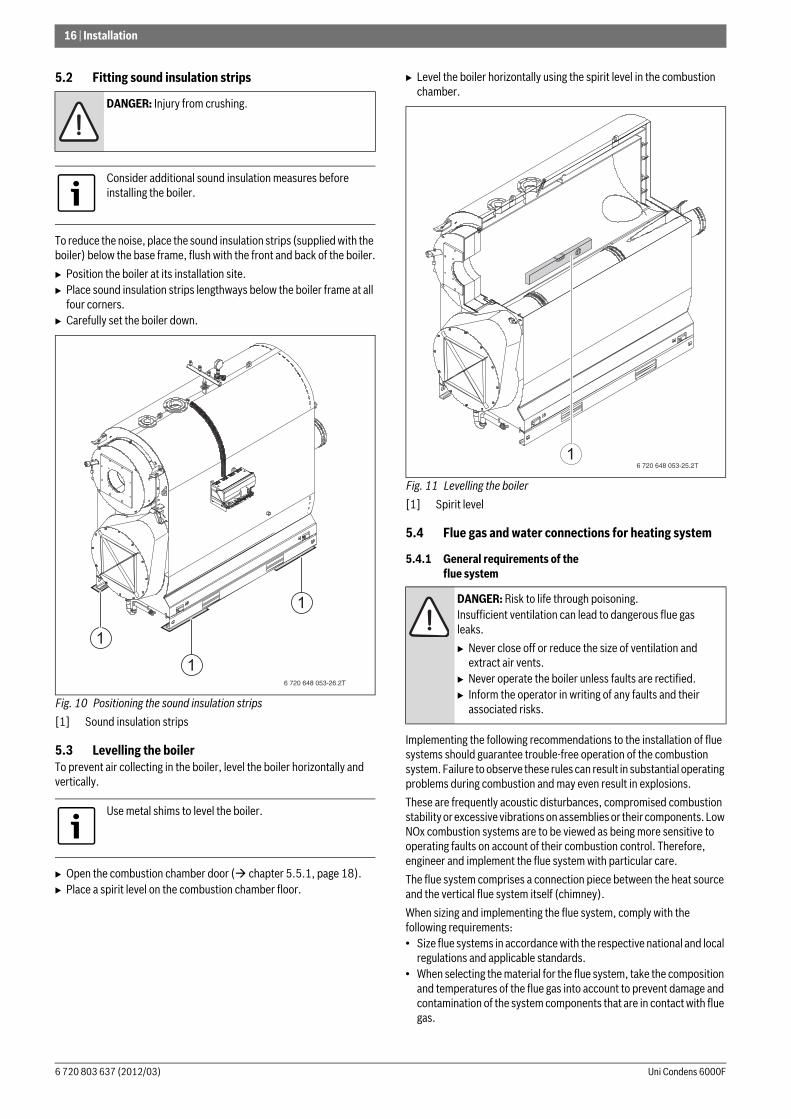
5.3 Levelling the boilerTo prevent air collecting in the boiler, level the boiler horizontally and vertically.
B Open the combustion chamber door ( chapter 5.5.1, page 18).B Place a spirit level on the combustion chamber floor.
B Level the boiler horizontally using the spirit level in the combustion chamber.
Fig. 11 Levelling the boiler
[1] Spirit level
5.4 Flue gas and water connections for heating system
5.4.1 General requirements of the flue system
Implementing the following recommendations to the installation of flue systems should guarantee trouble-free operation of the combustion system. Failure to observe these rules can result in substantial operating problems during combustion and may even result in explosions.
These are frequently acoustic disturbances, compromised combustion stability or excessive vibrations on assemblies or their components. Low NOx combustion systems are to be viewed as being more sensitive to operating faults on account of their combustion control. Therefore, engineer and implement the flue system with particular care.
The flue system comprises a connection piece between the heat source and the vertical flue system itself (chimney).
When sizing and implementing the flue system, comply with the following requirements:• Size flue systems in accordance with the respective national and local
regulations and applicable standards. • When selecting the material for the flue system, take the composition
and temperatures of the flue gas into account to prevent damage and contamination of the system components that are in contact with flue gas.
DANGER: Injury from crushing.
Consider additional sound insulation measures before installing the boiler.
Use metal shims to level the boiler.
6 720 648 053-26.2T
1
1
1 DANGER: Risk to life through poisoning.Insufficient ventilation can lead to dangerous flue gas leaks.
B Never close off or reduce the size of ventilation and extract air vents.
B Never operate the boiler unless faults are rectified. B Inform the operator in writing of any faults and their
associated risks.
6 720 648 053-25.2T1
Installation | 17
6 720 803 637 (2012/03)Uni Condens 6000F
• Only flue systems, which are approved for a flue gas temperature of at least 120 °C, may be used.
• Route the flue gas as directly as possible to the chimney considering the best possible flow characteristics (e.g. short, rising, and with the fewest possible bends). Provide a separate chimney flue for each boiler. Take the thermal expansion of the system into account.
• Implement deviations in the connection pieces as favourably as possible where flow is concerned by using bends or deflectors. Connection pieces with several deviations should be avoided, as they would have a detrimental effect on air-borne and structure-borne noise as well as the start-up pressure hammer. Prevent sharp-edged joints between rectangular connection flanges and the connection pipe. As with any reductions/expansions that may be required, the angle of the joint should not exceed 30°.
• Where possible, connection pieces should be joined to the chimney to provide optimum flow characteristics and with an incline (at an angle less than 45°). Any terminal pieces at the chimney outlets must ensure the free discharge of flue gas to atmosphere.
• Any condensate must be able to drain freely over the entire length, be treated and drained off in accordance with local regulations.
• Provide inspection apertures in accordance with local regulations, if necessary after discussion with the local authorising body.
• The chimney must be separated from the boiler (e.g. with compensators) to prevent the transfer of structure-borne noise.
• If a flue gas damper is installed in the flue system, integrate an "OPEN" limit switch into the boiler control system for safety reasons. Combustion must only be able to start when the feedback from the limit switch confirms that the flue damper is fully open. A temperature drop inside the boiler is possible on account of the time it takes the actuator to move the damper into position. Set the "CLOSE" limit position at the flue gas damper in such a way that it never closes fully. This prevents damage to the fitted burner through heat build up.
5.4.2 Fitting a sealing collarB Fit the sealing collar in accordance with the installation instructions
supplied.
5.4.3 Connecting the boiler to the pipework
Connecting the heating returnThe boiler has two inlet options for the return water. If separate system returns for differing return temperatures are used (e.g. underfloor heating, DHW heating), these can be routed to the boiler via separate return connections.
• RK1 = Low return temperature (e.g. underfloor heating)• RK2 = High return temperature (e.g. DHW heating)
On delivery, the return is sealed with a dummy flange. If using connection RK2:
B Remove dummy flange.
If there are no varying return temperatures, return connection RK1 is used.
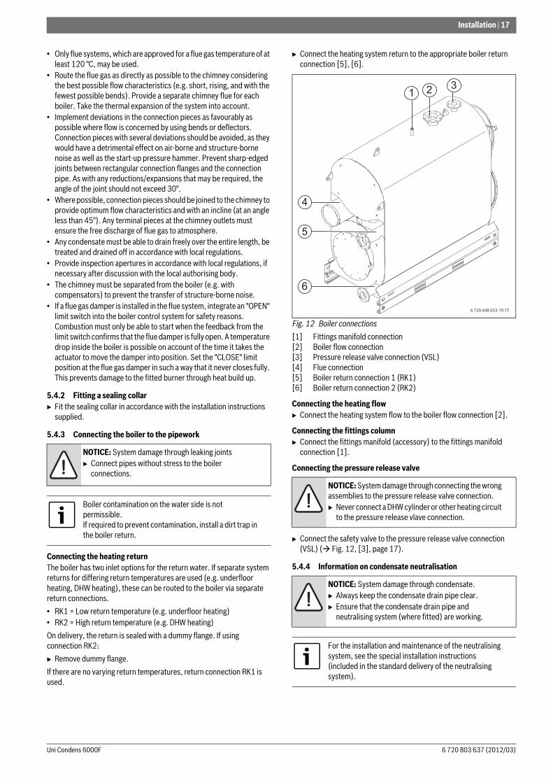
B Connect the heating system return to the appropriate boiler return connection [5], [6].
Fig. 12 Boiler connections
[1] Fittings manifold connection[2] Boiler flow connection[3] Pressure release valve connection (VSL)[4] Flue connection[5] Boiler return connection 1 (RK1)[6] Boiler return connection 2 (RK2)
Connecting the heating flowB Connect the heating system flow to the boiler flow connection [2].
Connecting the fittings columnB Connect the fittings manifold (accessory) to the fittings manifold
connection [1].
Connecting the pressure release valve
B Connect the safety valve to the pressure release valve connection (VSL) ( Fig. 12, [3], page 17).
5.4.4 Information on condensate neutralisation
NOTICE: System damage through leaking jointsB Connect pipes without stress to the boiler
connections.
Boiler contamination on the water side is not permissible.If required to prevent contamination, install a dirt trap in the boiler return.
NOTICE: System damage through connecting the wrong assemblies to the pressure release valve connection.B Never connect a DHW cylinder or other heating circuit
to the pressure release vlave connection.
NOTICE: System damage through condensate.B Always keep the condensate drain pipe clear.B Ensure that the condensate drain pipe and
neutralising system (where fitted) are working.
For the installation and maintenance of the neutralising system, see the special installation instructions (included in the standard delivery of the neutralising system).
6 720 648 053-19.1T
2 31
5
6
4
18 | Installation
Uni Condens 6000F6 720 803 637 (2012/03)
B Push the siphon provided (condensate drain pipe) onto the pipe connector ( Fig. 1, [5], page 6) on the flue gas collector.
B Tighten the union nut on the siphon.B Connect the drain hose to the siphon connector using a hose clip.
5.4.5 Filling the boiler and checking connectionsfor leaks
Before commissioning, check the heating system for tightness to ensure that no leaks will occur during operation.
B Fill the heating system with water ( chapter 6.1, page 24 and chapter 6.2, page 24).
B Check all connections for leaks.B Pressure test the heating system.B Check the flange connection and boiler connections
for leaks.B Check the pipework for leaks.B After the tightness test, reinstate all components that were taken out
of operation. B Ensure that all pressure, control and safety equipment is working
correctly.
5.5 Opening and closing the combustion chamber door
As standard, the combustion chamber door pivots open from left to right.
The following instructions assume the standard pivoting direction.
The combustion chamber door can be converted to open to the left.
5.5.1 Opening and closing the combustion chamber doorOpening the combustion chamber door
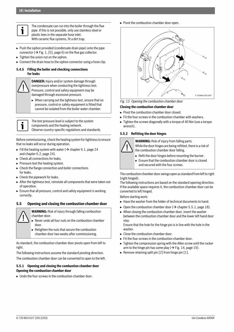
B Undo the four screws in the combustion chamber door.
B Pivot the combustion chamber door open.
Fig. 13 Opening the combustion chamber door
Closing the combustion chamber door
B Pivot the combustion chamber door closed.B Fit the four screws in the combustion chamber with washers.B Tighten the screws diagonally with a torque of 40 Nm (use a torque
wrench).
5.5.2 Refitting the door hinges
The combustion chamber door swings open as standard from left to right (right hinged). The following instructions are based on the standard opening direction.If the available space requires it, the combustion chamber door can be converted to left hinged.
Before starting work:B Have the washer from the folder of technical documents to hand.
B Open the combustion chamber door ( chapter 5.5.1, page 18).B When closing the combustion chamber door, insert the washer
between the combustion chamber door and the lower left hand door stay.Ensure that the hole for the hinge pin is in line with the hole in the washer.
B Close the combustion chamber door.B Fit the four screws in the combustion chamber door.B Tighten the compression spring with the Allen screw until the rocker
arm to the hinge pin has some play ( Fig. 14, page 19).B Remove retaining split pin [2] from hinge pin [1].
The condensate can run into the boiler through the flue pipe. If this is not possible, only use stainless steel or plastic tees in the separate hose inlet.With ceramic flue systems, fit a dirt trap.
DANGER: Injury and/or system damage through overpressure when conducting the tightness test.Pressure, control and safety equipment may be damaged through excessive pressure.
B When carrying out the tightness test, ensure that no pressure, control or safety equipment is fitted that cannot be isolated from the boiler water chamber.
The test pressure level is subject to the system components and the heating network.Observe country-specific regulations and standards.
WARNING: Risk of injury through falling combustion chamber door.B Never undo all four nuts on the combustion chamber
door.B Retighten the nuts that secure the combustion
chamber door two weeks after commissioning.
WARNING: Risk of injury from falling parts.While the door hinges are being refitted, there is a risk of the combustion chamber door falling.
B Refit the door hinges before mounting the burner.B Ensure that the combustion chamber door is closed
and secured with the four screws.
6 720 648 053-04.1T
Installation | 19
6 720 803 637 (2012/03)Uni Condens 6000F
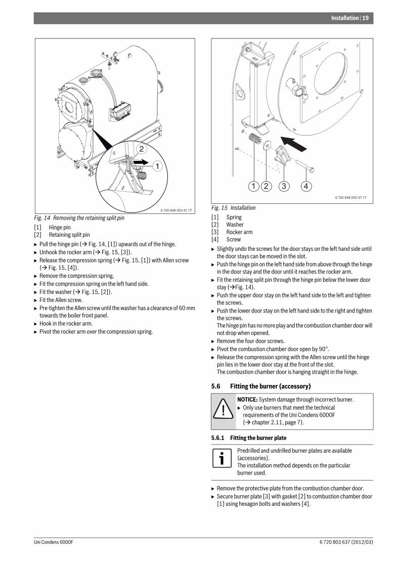
Fig. 14 Removing the retaining split pin
[1] Hinge pin[2] Retaining split pin
B Pull the hinge pin ( Fig. 14, [1]) upwards out of the hinge.B Unhook the rocker arm ( Fig. 15, [3]).B Release the compression spring ( Fig. 15, [1]) with Allen screw
( Fig. 15, [4]).B Remove the compression spring.B Fit the compression spring on the left hand side.B Fit the washer ( Fig. 15, [2]).B Fit the Allen screw.B Pre-tighten the Allen screw until the washer has a clearance of 60 mm
towards the boiler front panel.B Hook in the rocker arm.B Pivot the rocker arm over the compression spring.
Fig. 15 Installation
[1] Spring[2] Washer[3] Rocker arm[4] Screw
B Slightly undo the screws for the door stays on the left hand side until the door stays can be moved in the slot.
B Push the hinge pin on the left hand side from above through the hinge in the door stay and the door until it reaches the rocker arm.
B Fit the retaining split pin through the hinge pin below the lower door stay ( Fig. 14).
B Push the upper door stay on the left hand side to the left and tighten the screws.
B Push the lower door stay on the left hand side to the right and tighten the screws.The hinge pin has no more play and the combustion chamber door will not drop when opened.
B Remove the four door screws.B Pivot the combustion chamber door open by 90°.B Release the compression spring with the Allen screw until the hinge
pin lies in the lower door stay at the front of the slot.The combustion chamber door is hanging straight in the hinge.
5.6 Fitting the burner (accessory)
5.6.1 Fitting the burner plate
B Remove the protective plate from the combustion chamber door.B Secure burner plate [3] with gasket [2] to combustion chamber door
[1] using hexagon bolts and washers [4].
6 720 648 053-31.1T
1
2
NOTICE: System damage through incorrect burner.B Only use burners that meet the technical
requirements of the Uni Condens 6000F ( chapter 2.11, page 7).
Predrilled and undrilled burner plates are available (accessories).The installation method depends on the particular burner used.
6 720 648 053-37.1T
1 2 3 4
20 | Installation
Uni Condens 6000F6 720 803 637 (2012/03)
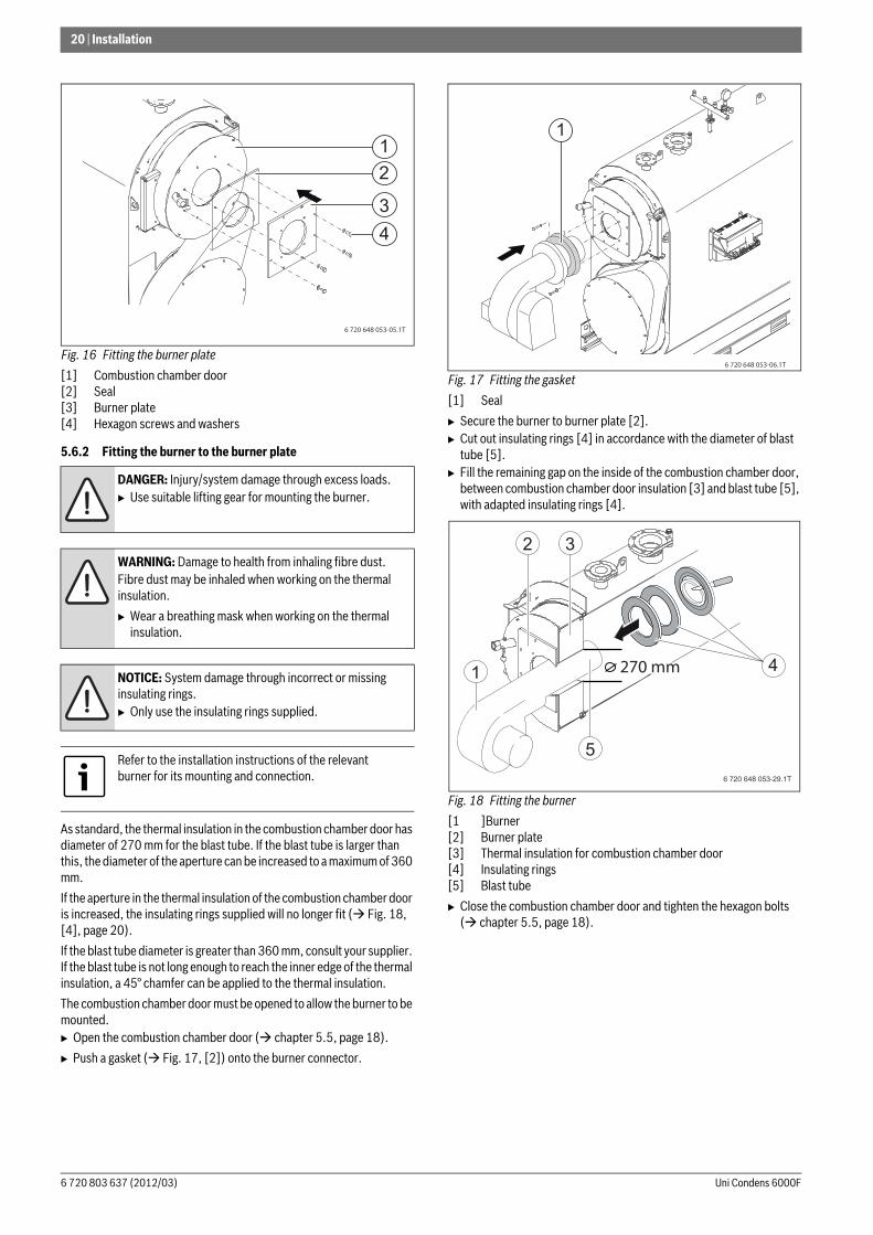
Fig. 16 Fitting the burner plate
[1] Combustion chamber door[2] Seal[3] Burner plate[4] Hexagon screws and washers
5.6.2 Fitting the burner to the burner plate
As standard, the thermal insulation in the combustion chamber door has diameter of 270 mm for the blast tube. If the blast tube is larger than this, the diameter of the aperture can be increased to a maximum of 360 mm.
If the aperture in the thermal insulation of the combustion chamber door is increased, the insulating rings supplied will no longer fit ( Fig. 18, [4], page 20).
If the blast tube diameter is greater than 360 mm, consult your supplier. If the blast tube is not long enough to reach the inner edge of the thermal insulation, a 45° chamfer can be applied to the thermal insulation.
The combustion chamber door must be opened to allow the burner to be mounted.B Open the combustion chamber door ( chapter 5.5, page 18).
B Push a gasket ( Fig. 17, [2]) onto the burner connector.
Fig. 17 Fitting the gasket
[1] Seal
B Secure the burner to burner plate [2].B Cut out insulating rings [4] in accordance with the diameter of blast
tube [5].B Fill the remaining gap on the inside of the combustion chamber door,
between combustion chamber door insulation [3] and blast tube [5], with adapted insulating rings [4].
Fig. 18 Fitting the burner
[1 ]Burner[2] Burner plate[3] Thermal insulation for combustion chamber door[4] Insulating rings[5] Blast tube
B Close the combustion chamber door and tighten the hexagon bolts ( chapter 5.5, page 18).
DANGER: Injury/system damage through excess loads.B Use suitable lifting gear for mounting the burner.
WARNING: Damage to health from inhaling fibre dust.Fibre dust may be inhaled when working on the thermal insulation.
B Wear a breathing mask when working on the thermal insulation.
NOTICE: System damage through incorrect or missing insulating rings.B Only use the insulating rings supplied.
Refer to the installation instructions of the relevant burner for its mounting and connection.
6 720 648 053-05.1T
3
1
4
2
6 720 648 053-06.1T
1
6 720 648 053-29.1T
1
2 3
5
4270 mm
Installation | 21
6 720 803 637 (2012/03)Uni Condens 6000F
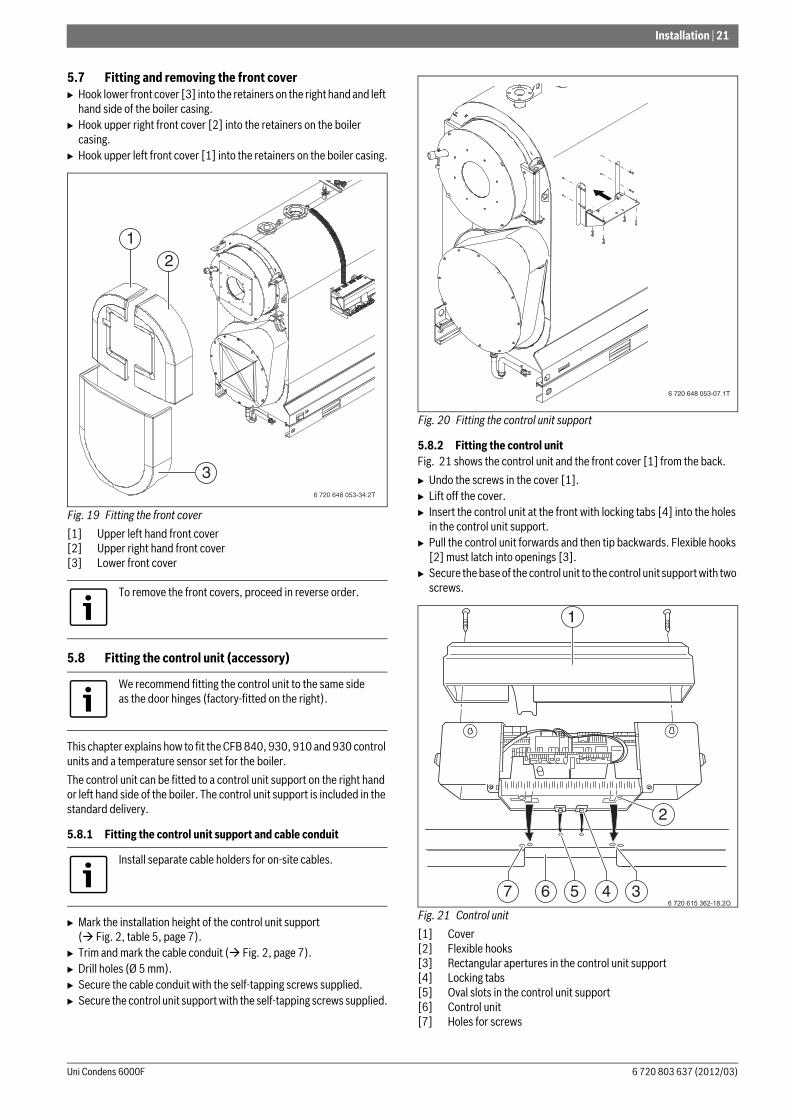
5.7 Fitting and removing the front coverB Hook lower front cover [3] into the retainers on the right hand and left
hand side of the boiler casing.B Hook upper right front cover [2] into the retainers on the boiler
casing.B Hook upper left front cover [1] into the retainers on the boiler casing.
Fig. 19 Fitting the front cover
[1] Upper left hand front cover[2] Upper right hand front cover[3] Lower front cover
5.8 Fitting the control unit (accessory)
This chapter explains how to fit the CFB 840, 930, 910 and 930 control units and a temperature sensor set for the boiler.
The control unit can be fitted to a control unit support on the right hand or left hand side of the boiler. The control unit support is included in the standard delivery.
5.8.1 Fitting the control unit support and cable conduit
B Mark the installation height of the control unit support ( Fig. 2, table 5, page 7).
B Trim and mark the cable conduit ( Fig. 2, page 7). B Drill holes (Ø 5 mm).B Secure the cable conduit with the self-tapping screws supplied.B Secure the control unit support with the self-tapping screws supplied.
Fig. 20 Fitting the control unit support
5.8.2 Fitting the control unitFig. 21 shows the control unit and the front cover [1] from the back.
B Undo the screws in the cover [1]. B Lift off the cover.B Insert the control unit at the front with locking tabs [4] into the holes
in the control unit support. B Pull the control unit forwards and then tip backwards. Flexible hooks
[2] must latch into openings [3].B Secure the base of the control unit to the control unit support with two
screws.
Fig. 21 Control unit
[1] Cover[2] Flexible hooks[3] Rectangular apertures in the control unit support[4] Locking tabs[5] Oval slots in the control unit support[6] Control unit[7] Holes for screws
To remove the front covers, proceed in reverse order.
We recommend fitting the control unit to the same side as the door hinges (factory-fitted on the right).
Install separate cable holders for on-site cables.
6 720 648 053-34.2T
12
3
6 720 648 053-07.1T
1
2
456 376 720 615 362-18.2O
22 | Installation
Uni Condens 6000F6 720 803 637 (2012/03)
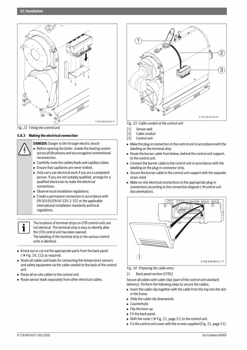
Fig. 22 Fitting the control unit
5.8.3 Making the electrical connection
B Knock out or cut out the appropriate parts from the back panel ( Fig. 24, [1]) as required.
B Route all cables and leads for connecting the temperature sensors and safety equipment via the cable conduit to the back of the control unit.
B Route all on-site cables to the control unit.B Route sensor leads separately from other electrical cables.
Fig. 23 Cable conduit at the control unit
[1] Sensor well[2] Cable conduit[3] Control unit
B Make the plug-in connection in the control unit in accordance with the labelling on the terminal strip.
B Route the burner cable from below, behind the control unit support, to the control unit.
B Connect the burner cable to the control unit in accordance with the labelling on the plug-in connector strip.
B Secure the burner cable to the control unit support with the separate strain relief.
B Make on-site electrical connections to the appropriate plug-in connections according to the connection diagram ( control unit documentation).
Fig. 24 Preparing the cable entry
[1 Back panel section (CFB)]
Secure all cables with cable clips (part of the control unit standard delivery). Perform the following steps to secure the cables:B Insert the cable clip together with the cable from the top into the slot
in the frame.B Slide the cable clip downwards.B Counterhold.B Flip the lever up.B Fit the back panel.B Refit the cover ( Fig. 21, page 21) to the control unit.B Fix the control unit cover with the screws supplied (Fig. 21, page 21).
DANGER: Danger to life through electric shock!B Before opening the boiler, isolate the heating system
across all life phases and secure against unintentional reconnection.
B Carefully route the cables/leads and capillary tubes.B Ensure that capillaries are never kinked.B Only carry out electrical work if you are a competent
person. If you are not suitably qualified, arrange for a qualified electrician to make the electrical connections.
B Observe local installation regulations.B Create a permanent connection in accordance with
EN 50165/EN 60 335-2-102 or the applicable international installation standards and local regulations.
The locations of terminal strips on CFB control units are not identical. The terminal strip is easy to identify after the CFB control unit has been opened. The labelling of the terminal strip in the various control units is identical.
6 720 648 053-08.1T
6 720 648 053-09.2T
1
2
3
6 720 648 053-21.1T
1
Installation | 23
6 720 803 637 (2012/03)Uni Condens 6000F
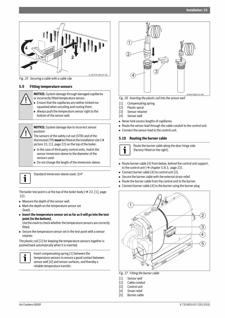
Fig. 25 Securing a cable with a cable clip
5.9 Fitting temperature sensors
The boiler test point is at the top of the boiler body ( 23, [1], page 22).
B Measure the depth of the sensor well.B Mark the depth on the temperature sensor set
(lead).B Insert the temperature sensor set as far as it will go into the test
point (to the bottom).Use the mark to check whether the temperature sensors are correctly fitted.
B Secure the temperature sensor set in the test point with a sensor retainer.
The plastic coil [2] for keeping the temperature sensors together is pushed back automatically when it is inserted.
Fig. 26 Inserting the plastic coil into the sensor well
[1] Compensating spring[2] Plastic spiral[3] Sensor retainer[4] Sensor well
B Never kink excess lengths of capillaries. B Route the sensor lead through the cable conduit to the control unit.B Connect the sensor lead to the control unit.
5.10 Routing the burner cable
B Route burner cable [4] from below, behind the control unit support, to the control unit ( chapter 5.8.3, page 22).
B Connect burner cable [4] to control unit [3].B Secure the burner cable with the external strain relief.B Route the burner cable from the control unit to the burner. B Connect burner cable [4] to the burner using the burner plug.
Fig. 27 Fitting the burner cable
[1] Sensor well[2] Cable conduit[3] Control unit[4] Strain relief[5] Burner cable
NOTICE: System damage through damaged capillaries or incorrectly fitted temperature sensor.B Ensure that the capillaries are neither kinked nor
squashed when uncoiling and routing them.B Always push the temperature sensor right to the
bottom of the sensor well.
NOTICE: System damage due to incorrect sensor position!The sensors of the safety cut-out (STB) and of the thermostat (TR) must be fitted at the installation site ( picture 23, [1], page 22) on the top of the boiler.
B In the case of third party control units, match the sensor immersion sleeve to the diameter of the sensors used.
B Do not change the length of the immersion sleeve.
Standard immersion sleeve used: 3/4"
Insert compensating spring [1] between the temperature sensors to ensure a good contact between sensor well [4] and sensor surfaces, and thereby a reliable temperature transfer.
6 720 615 362-20.1SL
Route the burner cable along the door hinge side (factory-fitted on the right).
6720615883-32.1RS
1
2
34
2
3
4
5
1
24 | Commissioning
Uni Condens 6000F6 720 803 637 (2012/03)
6 Commissioning
B Complete the commissioning report ( chapter 6.6, page 25).
6.1 Flushing the heating system
To prevent contamination in the boiler, flush the heating system prior to commissioning.
B Flush the system prior to connection to the boiler.-or-B Isolate the heating flow and return at the boiler.B Connect the heating flow to a water connection.B Connect hose to the heating return of the heating system.B Route hose from the heating return to a drain.B Open connected consumers (e.g. radiators).B Flush the heating system with fresh water until clear water emerges
from the heating return.B Drain the heating system.
6.2 Filling the heating system
The fill and top-up water quality must comply with the specifications in the operator's log supplied.
The pH value of the heating water increases after the heating system has been filled. After 3 – 6 months (initial service) check whether the pH value of the heating water has settled down.
B Adjust the pre-charge pressure of the expansion vessel to the required pressure (only for sealed unvented systems).
B Open the mixing and shut-off valves on the heating water side.
B Fill the heating system slowly and observe the pressure gauge whilst doing so.
B Vent the heating system via the radiator air vent valves.
If the water pressure drops as a result of venting the system:B Top up the system with water.B Carry out a leak test in accordance with locally applicable regulations.B After the tightness test, reinstate all components that were taken out
of operation.B Ensure that all pressure, control and safety equipment is functioning
correctly.
Once the boiler has been tested for tightness and no leaks have been found:B Set the correct operating pressure.B Close the automatic air vent valve.
6.3 Preparing the heating system for operationObserve the following points during commissioning:
B Before commissioning, vent the heating system via the ventilation facilities provided for this purpose.
B Check that the inspection aperture on the flue gas collector is closed.B Check that the combustion chamber door is securely closed.B Check that the safety equipment (e.g. safety valve, minimum and
maximum pressure limiters, high limit safety cut-out) is functioning correctly.
B Check that the required operating pressure has been achieved.B Check the flange connections and other connections for tightness.B Check the control unit connections and temperature sensor
positions.B Fill the condensate siphon.
6.4 Commissioning the control unit and burnerBy commissioning the control unit you automatically commission the burner as well. The burner can then be started by the control unit. For further information, see the installation instructions of the relevant control unit or burner.
B Use the control unit to commission the boiler.B Set the control unit parameters ( chapter 6.5, page 25).B Observe the commissioning times ( chapter 6.1, page 24)B Complete the commissioning report in the technical documentation
of the burner.
NOTICE: Risk of boiler damage through contaminated combustion air.B Never operate the boiler in very dusty conditions, e.g.
if building work is taking place in the installation room.B Ensure adequate ventilation.B Never use or store chlorinated cleaning agents or
halogenated hydrocarbons (as contained in spray cans, solvents or cleaning agents, paints and adhesives, for example) in the boiler room.
B A burner contaminated during building work must be cleaned before commissioning.
If the heating system contains several heating circuits, these must be flushed one after the other.
NOTICE: System damage through temperature stresses.B Only fill the heating system when cold (the flow
temperature must not exceed 40 °C).B During operation, only fill the heating system via the
fill valve in the heating system pipework (return).
CAUTION: Health risk through contaminated drinking water.B Observe all country-specific regulations and
standards regarding the prevention of drinking water contamination. In Europe, observe standard.
Open the automatic air vent valve only briefly for venting.
Commissioning | 25
6 720 803 637 (2012/03)Uni Condens 6000F
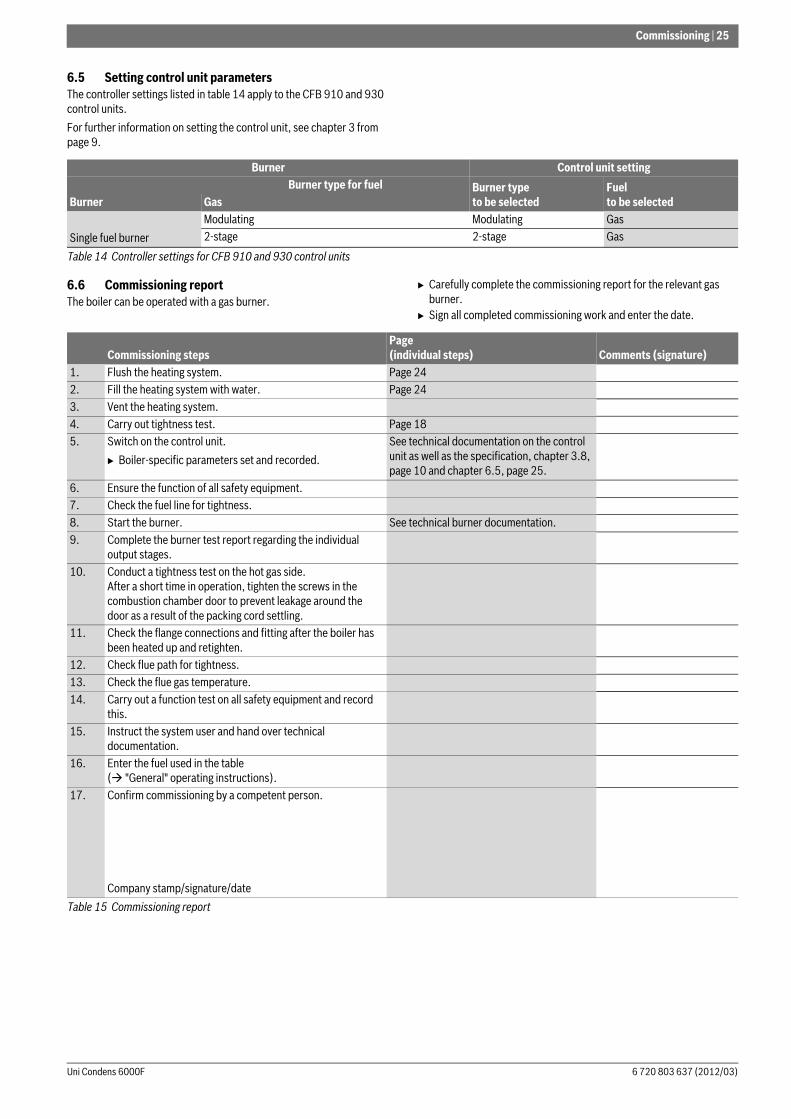
6.5 Setting control unit parametersThe controller settings listed in table 14 apply to the CFB 910 and 930 control units.
For further information on setting the control unit, see chapter 3 from page 9.
6.6 Commissioning reportThe boiler can be operated with a gas burner.
B Carefully complete the commissioning report for the relevant gas burner.
B Sign all completed commissioning work and enter the date.
Burner Control unit setting Burner type for fuel Burner type
to be selectedFuelto be selectedBurner Gas
Single fuel burner
Modulating Modulating Gas 2-stage 2-stage Gas
Table 14 Controller settings for CFB 910 and 930 control units
Commissioning stepsPage (individual steps) Comments (signature)
1. Flush the heating system. Page 242. Fill the heating system with water. Page 243. Vent the heating system.4. Carry out tightness test. Page 185. Switch on the control unit.
B Boiler-specific parameters set and recorded.
See technical documentation on the control unit as well as the specification, chapter 3.8, page 10 and chapter 6.5, page 25.
6. Ensure the function of all safety equipment.7. Check the fuel line for tightness.8. Start the burner. See technical burner documentation.9. Complete the burner test report regarding the individual
output stages.10. Conduct a tightness test on the hot gas side.
After a short time in operation, tighten the screws in the combustion chamber door to prevent leakage around the door as a result of the packing cord settling.
11. Check the flange connections and fitting after the boiler has been heated up and retighten.
12. Check flue path for tightness.13. Check the flue gas temperature.14. Carry out a function test on all safety equipment and record
this.15. Instruct the system user and hand over technical
documentation.16. Enter the fuel used in the table
( "General" operating instructions).17. Confirm commissioning by a competent person.
Company stamp/signature/date
Table 15 Commissioning report
26 | Shutting down
Uni Condens 6000F6 720 803 637 (2012/03)
7 Shutting down
7.1 Shutting down the heating systemShut down your heating system via the control unit. Switching off the control unit also switches off the burner automatically.
B Set the On/Off switch of the control unit to "0" (Off).B Isolate the fuel supply to the burner.
7.2 Shutting down the heating system in an emergency
B In dangerous situations, immediately close the main fuel shut-off valve and the power supply of the heating system via the boiler room main MCB/fuse or the heating system emergency stop switch.
B Isolate the fuel supply to the burner.B Never put your life at risk. Your own safety is paramount.
8 Inspection and maintenance
8.1 General notes
Offer your customer an annual contract covering inspection and responsive service. For the work covered by such a contract, see chapter 8.5 "Inspection and maintenance reports", page 30.
8.2 Preparing the boiler for inspection and maintenance
B Shut down the heating system ( chapter 7.1, page 26).
Prior to opening the combustion chamber door:B Check the general condition of the heating system.B Visual inspection and function check of the heating system.B Check all system parts that carry fuel or water for leaks and visible
corrosion.
B Open the combustion chamber door ( chapter 5.5.1, page 20).
8.3 Cleaning the boiler
8.3.1 Preparing the boiler for cleaning with brushes
B Remove the front cover ( chapter 5.7, page 21).B Remove the burner.B Open the combustion chamber door ( chapter 5.5, page 18).B Clean the combustion chamber and the heating surfaces.B Open the flue gas collector cover
( chapter 8.3.5, page 28).B Open the reversing chamber cover
( chapter 8.3.5, page 28).B Check the flue gas collector and condensate drain, and clean via the
inspection aperture if required.
8.3.2 Cleaning the boiler with cleaning brushes
B Clean the heating surfaces of the combustion chamber ( Fig. 28, [1], page 27) with the cleaning brush ( Fig. 28, [2], page 27).
NOTICE: Risk of system damage through frost.When there is a frost, the heating system can freeze up if it is not operational, e.g. because of a fault shutdown.
B When there is a risk of frost, protect your heating system against freezing up.
B If your heating system has been shut down for several days due to a fault shutdown and there is a risk of frost, drain the heating water at the drain & fill valve. Also leave the air vent valve at the highest point in the system open.
NOTICE: Risk of system damage through frost.The heating system can freeze up as a result of a power failure or if the power has been switched off.
B Check the "Control unit settings" to ensure the system remains operational (especially when there is a risk of frost).
Only in emergencies, switch OFF the heating system via the boiler room MCB/fuse or the heating system emergency stop switch.
NOTICE: System damage due to inadequate cleaning and maintenance.B Carry out cleaning and maintenance at least once a
year. In the course of this work, check the entire heating system including the neutralising system for correct function.
B Immediately correct all faults to prevent system damage.
Annual inspection and service are part of the warranty terms.
Use only original, genuine spare parts from the manufacturer. Spare parts can be ordered from the manufacturer's spare parts catalogue.
DANGER: Risk to life from electric shock when the heating system is open.B Prior to opening the heating system: Isolate the
heating system from the mains power supply via the heating system emergency stop switch or the corresponding domestic MCB/fuse.
B Safeguard the heating system against unintentional reconnection.
DANGER: Risk to life through explosion of flammable gases!B Work on gas components must only be carried out by
a competent person.
If gas lines have to be detached from the gas burner, the combustion chamber door may only be opened by a competent person.
CAUTION: Risk of injury through falling parts.B Prior to opening the doors, ensure that the hinge pin
is correctly fitted in the combustion chamber door and secured with a spring washer.
WARNING: System damage through using incorrect cleaning equipment.B If cleaning with a brush, use only original cleaning
brushes from the manufacturer.B When cleaning only use brushes made of nylon or of
stainless steel with a stainless steel linkage.
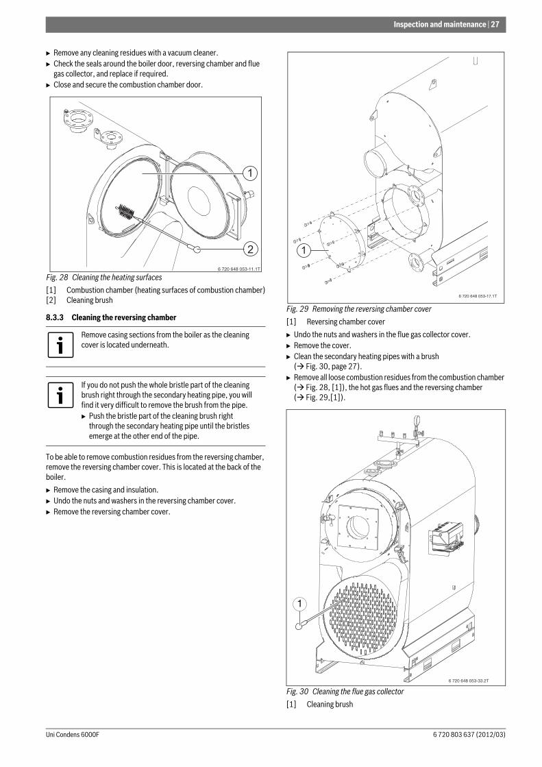
Inspection and maintenance | 27
6 720 803 637 (2012/03)Uni Condens 6000F
B Remove any cleaning residues with a vacuum cleaner.B Check the seals around the boiler door, reversing chamber and flue
gas collector, and replace if required.B Close and secure the combustion chamber door.
Fig. 28 Cleaning the heating surfaces
[1] Combustion chamber (heating surfaces of combustion chamber)[2] Cleaning brush
8.3.3 Cleaning the reversing chamber
To be able to remove combustion residues from the reversing chamber, remove the reversing chamber cover. This is located at the back of the boiler.
B Remove the casing and insulation.B Undo the nuts and washers in the reversing chamber cover.B Remove the reversing chamber cover.
Fig. 29 Removing the reversing chamber cover
[1] Reversing chamber cover
B Undo the nuts and washers in the flue gas collector cover.B Remove the cover.B Clean the secondary heating pipes with a brush
( Fig. 30, page 27).B Remove all loose combustion residues from the combustion chamber
( Fig. 28, [1]), the hot gas flues and the reversing chamber ( Fig. 29,[1]).
Fig. 30 Cleaning the flue gas collector
[1] Cleaning brush
Remove casing sections from the boiler as the cleaning cover is located underneath.
If you do not push the whole bristle part of the cleaning brush right through the secondary heating pipe, you will find it very difficult to remove the brush from the pipe.B Push the bristle part of the cleaning brush right
through the secondary heating pipe until the bristles emerge at the other end of the pipe.
6 720 648 053-11.1T
2
1
6 720 648 053-17.1T
1
1
6 720 648 053-33.2T
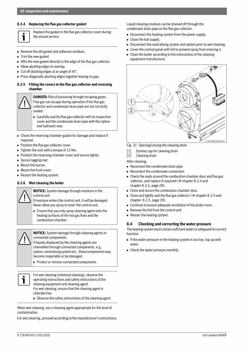
28 | Inspection and maintenance
Uni Condens 6000F6 720 803 637 (2012/03)
8.3.4 Replacing the flue gas collector gasket
B Remove the old gasket and adhesive residues.B Trim the new gasket.B Affix the new gasket directly to the edge of the flue gas collector.B Allow abutting edges to overlap.B Cut off abutting edges at an angle of 45°.B Press diagonally abutting edges together leaving no gap.
8.3.5 Fitting the covers to the flue gas collector and reversing chamber
B Check the reversing chamber gasket for damage and replace if required.
B Position the flue gas collector cover.B Tighten the nuts with a torque of 15 Nm.B Position the reversing chamber cover and secure tightly.B Secure lagging mat.B Mount the burner.B Mount the front cover.B Restart the heating system.
8.3.6 Wet-cleaning the boiler
When wet-cleaning, use a cleaning agent appropriate for the level of contamination.
For wet cleaning, proceed according to the manufacturer's instructions.
Liquid cleaning residues can be drained off through the condensate drain pipe on the flue gas collector.
B Disconnect the heating system from the power supply.B Close the fuel supply. B Disconnect the neutralising system and siphon prior to wet cleaning.B Cover the control panel with foil to prevent spray from entering it. B Clean the boiler according to the instructions of the cleaning
equipment manufacturer.
Fig. 31 Opening/closing the cleaning drain
[1] Dummy cap for cleaning drain[2] Cleaning drain
After cleaning:B Reconnect the condensate drain pipe.B Reconnect the condensate connection.B Check the seals around the combustion chamber door and flue gas
collector, and replace if required ( chapter 8.3.4 and chapter 8.3.5, page 28).
B Close and secure the combustion chamber door.B Close and tightly seal the flue gas collector ( chapter 8.3.4 and
chapter 8.3.5, page 28).B Continue to ensure adequate ventilation of the boiler room.B Remove the foil from the control unit.B Restart the heating system.
8.4 Checking and correcting the water pressureThe heating system must contain sufficient water to safeguard its correct function.
B If the water pressure in the heating system is too low, top up with water.
B Check the water pressure monthly.
Replace the gasket in the flue gas collector cover during the annual service.
DANGER: Risk of poisoning through escaping gases.Flue gas can escape during operation if the flue gas collector and condensate drain pipe are not correctly sealed.
B Carefully seal the flue gas collector with its inspection cover and the condensate drain pipe with the siphon and hydraulic seal.
NOTICE: System damage through moisture in the control unit.If moisture enters the control unit, it will be damaged. Never allow any spray to enter the control unit.
B Ensure that you only spray cleaning agent onto the heating surfaces of the hot gas flues and the combustion chamber.
NOTICE: System damage through cleaning agents in connected components.If liquids displaced by the cleaning agents are channelled through connected components, e.g. siphon, neutralising system etc., these components may become inoperable or be damaged.
B Protect or remove connected components.
For wet cleaning (chemical cleaning), observe the operating instructions and safety instructions of the cleaning equipment and cleaning agent.For wet cleaning, ensure that the cleaning agent is chloride-free.B Observe the safety instructions of the cleaning agent.
1
2
6 720 648 053-03.2T
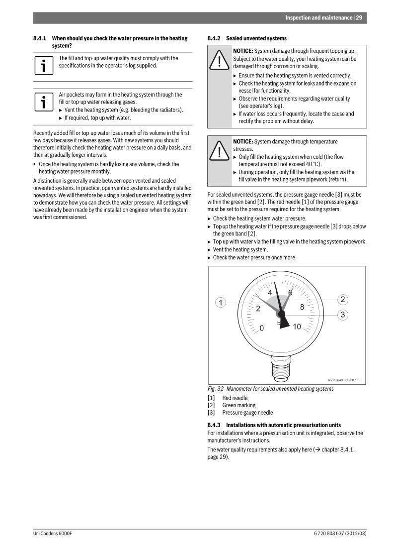
Inspection and maintenance | 29
6 720 803 637 (2012/03)Uni Condens 6000F
8.4.1 When should you check the water pressure in the heating system?
Recently added fill or top-up water loses much of its volume in the first few days because it releases gases. With new systems you should therefore initially check the heating water pressure on a daily basis, and then at gradually longer intervals.
• Once the heating system is hardly losing any volume, check the heating water pressure monthly.
A distinction is generally made between open vented and sealed unvented systems. In practice, open vented systems are hardly installed nowadays. We will therefore be using a sealed unvented heating system to demonstrate how you can check the water pressure. All settings will have already been made by the installation engineer when the system was first commissioned.
8.4.2 Sealed unvented systems
For sealed unvented systems, the pressure gauge needle [3] must be within the green band [2]. The red needle [1] of the pressure gauge must be set to the pressure required for the heating system.
B Check the heating system water pressure.B Top up the heating water if the pressure gauge needle [3] drops below
the green band [2].B Top up with water via the filling valve in the heating system pipework.B Vent the heating system.B Check the water pressure once more.
Fig. 32 Manometer for sealed unvented heating systems
[1] Red needle[2] Green marking[3] Pressure gauge needle
8.4.3 Installations with automatic pressurisation unitsFor installations where a pressurisation unit is integrated, observe the manufacturer's instructions.
The water quality requirements also apply here ( chapter 8.4.1, page 29).
The fill and top-up water quality must comply with the specifications in the operator's log supplied.
Air pockets may form in the heating system through the fill or top-up water releasing gases.B Vent the heating system (e.g. bleeding the radiators).B If required, top up with water.
NOTICE: System damage through frequent topping up.Subject to the water quality, your heating system can be damaged through corrosion or scaling.
B Ensure that the heating system is vented correctly.B Check the heating system for leaks and the expansion
vessel for functionality.B Observe the requirements regarding water quality
(see operator's log).B If water loss occurs frequently, locate the cause and
rectify the problem without delay.
NOTICE: System damage through temperature stresses.B Only fill the heating system when cold (the flow
temperature must not exceed 40 °C).B During operation, only fill the heating system via the
fill valve in the heating system pipework (return).
6 720 648 053-30.1T
13
2

30 | Inspection and maintenance
Uni Condens 6000F6 720 803 637 (2012/03)
8.5 Inspection and maintenance reportsThe inspection and maintenance reports provide an overview of the required inspection and service steps that should be carried out annually.
Complete these reports after inspections and service. The report can also be used as copying template.
B Sign and date the completed inspection work.
Warranty: Annual inspection and service are part of the warranty terms.
Inspection workPage (individual steps) Notes
1. Check the general condition of the heating system (visual inspection).2. Check the heating system function.3. Check the components in contact with fuel and water throughout the
system for the following:
• Tightness• Visible signs of corrosion• Signs of ageing
4. Check the combustion chamber and heating surface for contamination and clean them. For this, shut down the heating system.
Page 26
5. Check gaskets/packing cords on combustion chamber door and replace if required.
6. Check and clean the burner.
B Visual inspection and remove any contamination.B Check all safety equipment (safety shutdown).B Function checkB Flue gas analysis with test report for each output stage.
See technical burner documentation.
7. Check the flue for function and safety. See technical burner documentation.8. Check the hydraulic seal of the condensate siphon and replace if required.9. Check the water pressure and pre-charge pressure of the expansion vessel. Page 2810. Check the control unit settings are suitable and adjust if required. See technical control unit
documentation.12. Test all safety equipment (safety shutdown) and record findings.
For example:
B High limit safety cut-outB Pressure limiter min.B Pressure limiter max. (if installed)B Other safety equipment.
13. Conduct a water analysis and record the results in the operator's log:
B pH valueB Residual hardnessB Oxygen binderB PhosphateB Electrical conductivityB AppearanceB Check water records (e.g. amount of top-up water) in the operator's log.
14. Check the neutralisation system.15. Final check of the inspection work, take measurements and record values
and test results.
Table 16 Inspection report
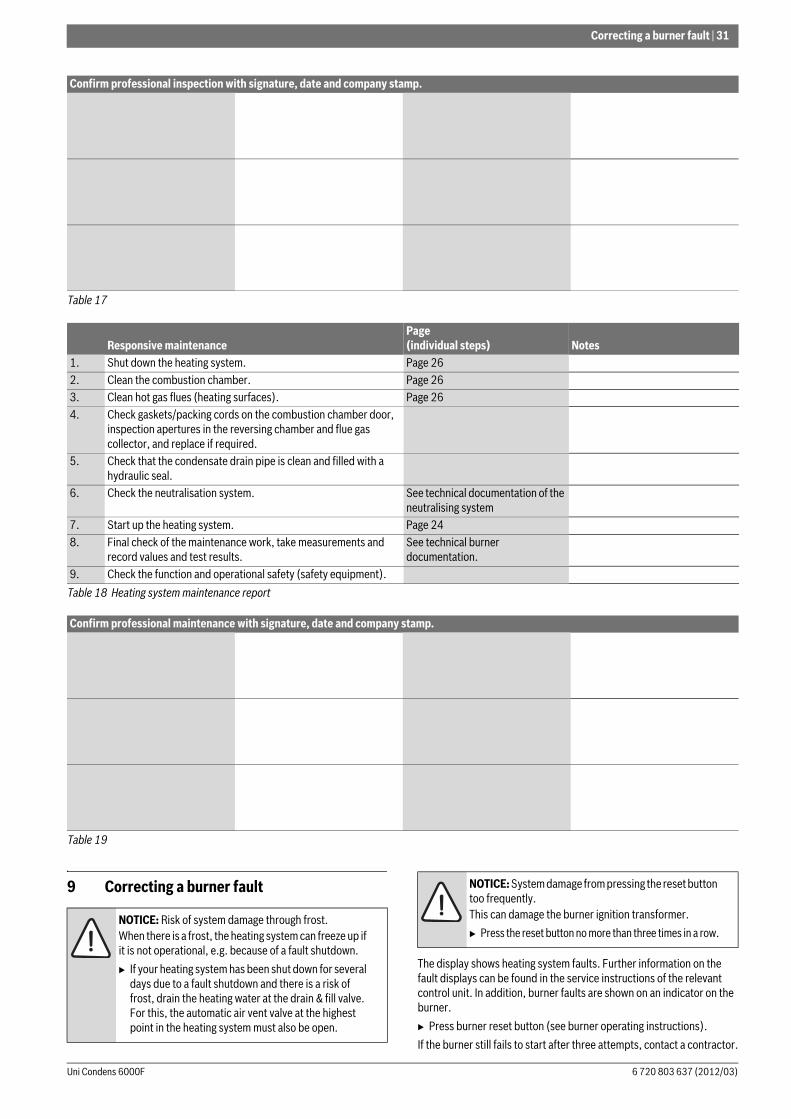
Correcting a burner fault | 31
6 720 803 637 (2012/03)Uni Condens 6000F
9 Correcting a burner fault
The display shows heating system faults. Further information on the fault displays can be found in the service instructions of the relevant control unit. In addition, burner faults are shown on an indicator on the burner.
B Press burner reset button (see burner operating instructions).
If the burner still fails to start after three attempts, contact a contractor.
Confirm professional inspection with signature, date and company stamp.
Table 17
Responsive maintenancePage (individual steps) Notes
1. Shut down the heating system. Page 262. Clean the combustion chamber. Page 263. Clean hot gas flues (heating surfaces). Page 264. Check gaskets/packing cords on the combustion chamber door,
inspection apertures in the reversing chamber and flue gas collector, and replace if required.
5. Check that the condensate drain pipe is clean and filled with a hydraulic seal.
6. Check the neutralisation system. See technical documentation of the neutralising system
7. Start up the heating system. Page 248. Final check of the maintenance work, take measurements and
record values and test results.See technical burner documentation.
9. Check the function and operational safety (safety equipment).
Table 18 Heating system maintenance report
Confirm professional maintenance with signature, date and company stamp.
Table 19
NOTICE: Risk of system damage through frost.When there is a frost, the heating system can freeze up if it is not operational, e.g. because of a fault shutdown.
B If your heating system has been shut down for several days due to a fault shutdown and there is a risk of frost, drain the heating water at the drain & fill valve. For this, the automatic air vent valve at the highest point in the heating system must also be open.
NOTICE: System damage from pressing the reset button too frequently.This can damage the burner ignition transformer.
B Press the reset button no more than three times in a row.
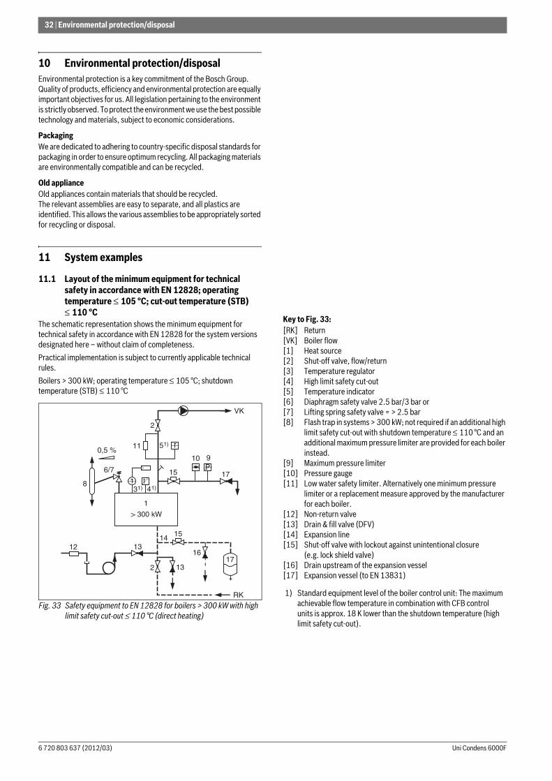
32 | Environmental protection/disposal
Uni Condens 6000F6 720 803 637 (2012/03)
10 Environmental protection/disposalEnvironmental protection is a key commitment of the Bosch Group. Quality of products, efficiency and environmental protection are equally important objectives for us. All legislation pertaining to the environment is strictly observed. To protect the environment we use the best possible technology and materials, subject to economic considerations.
PackagingWe are dedicated to adhering to country-specific disposal standards for packaging in order to ensure optimum recycling. All packaging materials are environmentally compatible and can be recycled.
Old applianceOld appliances contain materials that should be recycled.The relevant assemblies are easy to separate, and all plastics are identified. This allows the various assemblies to be appropriately sorted for recycling or disposal.
11 System examples
11.1 Layout of the minimum equipment for technical safety in accordance with EN 12828; operating temperature ≤ 105 °C; cut-out temperature (STB) ≤ 110 °C
The schematic representation shows the minimum equipment for technical safety in accordance with EN 12828 for the system versions designated here – without claim of completeness.
Practical implementation is subject to currently applicable technical rules.
Boilers > 300 kW; operating temperature ≤ 105 °C; shutdown temperature (STB) ≤ 110 °C
Fig. 33 Safety equipment to EN 12828 for boilers > 300 kW with high limit safety cut-out ≤ 110 °C (direct heating)
Key to Fig. 33:[RK] Return[VK] Boiler flow[1] Heat source[2] Shut-off valve, flow/return [3] Temperature regulator[4] High limit safety cut-out[5] Temperature indicator[6] Diaphragm safety valve 2.5 bar/3 bar or[7] Lifting spring safety valve = > 2.5 bar[8] Flash trap in systems > 300 kW; not required if an additional high
limit safety cut-out with shutdown temperature ≤ 110 °C and an additional maximum pressure limiter are provided for each boiler instead.
[9] Maximum pressure limiter[10] Pressure gauge[11] Low water safety limiter. Alternatively one minimum pressure
limiter or a replacement measure approved by the manufacturer for each boiler.
[12] Non-return valve[13] Drain & fill valve (DFV)[14] Expansion line[15] Shut-off valve with lockout against unintentional closure
(e.g. lock shield valve)[16] Drain upstream of the expansion vessel[17] Expansion vessel (to EN 13831)
2
11
9
17156/7
12 1314 15
1617
2 13
RK
VK
8
0,5 %
P
1
> 300 kW
10
51)
41)31)
1) Standard equipment level of the boiler control unit: The maximum achievable flow temperature in combination with CFB control units is approx. 18 K lower than the shutdown temperature (high limit safety cut-out).
Keyword index | 33
6 720 803 637 (2012/03)Uni Condens 6000F
Keyword index
AAbout the appliance .................................................................... 4
Appliance description............................................................. 5CE Declaration of Conformity................................................... 4Correct use ........................................................................... 4Operating conditions .............................................................. 4Overview of possible fuels ....................................................... 5Scope of supply ..................................................................... 4
Accessories ............................................................................... 4Appliance description ................................................................. 5Assembly aids ............................................................................ 5
BBoiler cover ............................................................................. 21Burner .................................................................................... 19Burner cable ............................................................................ 23Burner plate............................................................................. 19
CCE Declaration of Conformity ....................................................... 4Check all connections for leaks ................................................... 18Checking and correcting the water pressure ................................. 28checking and correcting the water pressure in sealed
unvented systems ................................................................ 29Cleaning.................................................................................. 26Combustion chamber door......................................................... 18Commissioning ........................................................................ 24
Commissioning the burner .................................................... 24Commissioning the control unit.............................................. 24Filling the heating system ...................................................... 24Flushing the heating system .................................................. 24Preparing the heating system for operation.............................. 24
Commissioning report ............................................................... 25commissioning the burner.......................................................... 24commissioning the control unit ................................................... 24Connecting the boiler to the pipework ......................................... 17Connection on the flue gas and water sides................................... 16Control unit ............................................................................. 21Correct use................................................................................ 4
DData plate.................................................................................. 5Dimensions ............................................................................... 7Disposal .................................................................................. 32
EElectrical connection................................................................. 22Environmental protection .......................................................... 32Explanation of symbols................................................................ 3
FFilling the boiler........................................................................ 18filling the heating system ........................................................... 24Fitting sensors ......................................................................... 23Fitting the boiler front cover ....................................................... 21Fitting the burner...................................................................... 19Fitting the burner plate .............................................................. 19fitting the burner to the burner plate............................................ 20Fitting the control unit ............................................................... 21Flue gas and water connections for heating system........................ 16Flue gas collector...................................................................... 27Flue pipe sealing collar .............................................................. 17flushing the heating system ........................................................ 24Fuels ........................................................................................ 5
GGuidelines ................................................................................ 9
HHeating flow ............................................................................ 17Heating return ......................................................................... 17
IInspection............................................................................... 26Inspection and maintenance ...................................................... 26
Checking and correcting the water pressure ............................ 28Checking and correcting the water pressure in sealed unvented systems ................................................................ 29Cleaning heating surfaces and turbulators with a cleaning brush. 26Cleaning the boiler .............................................................. 26Cleaning the flue gas collector ............................................... 27Fitting the cleaning cover...................................................... 28General information............................................................. 26Preparing the boiler ............................................................. 26Wet-cleaning the boiler ........................................................ 28
Inspection cover ...................................................................... 28Inspection report ..................................................................... 30Inspection reports.................................................................... 30Installation .............................................................................. 15
Check all connections for leaks.............................................. 18Connecting the boiler to the pipework .................................... 17Filling the boiler .................................................................. 18Fitting sensors .................................................................... 23Fitting the boiler front cover.................................................. 21Fitting the burner ................................................................ 19Fitting the burner plate......................................................... 19Fitting the burner to the burner plate...................................... 20Fitting the control unit.......................................................... 21Flow safety line ................................................................... 17Flue gas and water connections for heating system................... 16Heating flow ....................................................................... 17Heating return..................................................................... 17Levelling the boiler .............................................................. 16Making the electrical connection............................................ 22Recommended wall clearances.............................................. 15Routing the burner cable ...................................................... 23Siting the boiler................................................................... 15Sound insulation mats.......................................................... 16
LLevelling ................................................................................. 16Levelling the boiler ................................................................... 16
MMaintenance report .................................................................. 30Maintenance reports ................................................................ 30Making the electrical connection ................................................ 22Minimum wall clearances .......................................................... 15
NNeutralisation.......................................................................... 17
OOld appliance .......................................................................... 32Operating conditions .................................................................. 4Overview of Uni Condens 6000F.................................................. 6

34 | Keyword index
Uni Condens 6000F6 720 803 637 (2012/03)
PPackaging ............................................................................... 32Preparing the heating system for operation .................................. 24Prior to commissioning
Converting the combustion chamber door ............................... 18Opening the combustion chamber door .................................. 18
Product description .................................................................... 5
RRecommended wall clearances................................................... 15Recycling ................................................................................ 32Regulations ............................................................................... 9Routing the burner cable ........................................................... 23
SSafety equipment ....................................................................... 4Safety instructions ..................................................................... 3Safety pipe flow ....................................................................... 17Scope of supply ......................................................................... 4Service ................................................................................... 26Setting parameters................................................................... 25Shut down the heating system.................................................... 26Shutdown
Shutting down the heating system in emergencies .................... 26Shutting down ......................................................................... 26
Shut down the heating system ............................................... 26shutting down the heating system in emergencies ......................... 26Siting...................................................................................... 15Siting the boiler........................................................................ 15Sound insulation mats............................................................... 16Standards ................................................................................. 9System examples ..................................................................... 32
TTechnical Data ....................................................................... 7–8
Dimensions........................................................................... 7Output data .......................................................................... 8
Temperature sensor ................................................................. 23Tools ........................................................................................ 5Transport ................................................................................ 13
Heavy duty rollers ................................................................ 14Lifting with a crane............................................................... 13Moving the boiler with a forklift truck ................................ 13–14Moving the boiler with two pallet trucks............................. 13–14
Type overview............................................................................ 4
WWater pressure ........................................................................ 28

| 35
6 720 803 637 (2012/03)Uni Condens 6000F
Notes
������������������� ���������������������������������������������� !��������""��"�#"��#$�%���""��"�#"��!&&&'����'��('��)���&����
�� �������������"!""�*��������"!��*����+&&&'����'��'�,
United KingdomBosch Thermotechnology
Cotswold Way, Warndon, Worcester WR4 9SWAll Enquiries: 0844 892 3004
http://www.boschthermotechnology.co.uk/