UNDERWATER NOISE...noise (IMO MEPC.1/Circ.833 Guidelines for the Reduction of Underwater Noise from...
38
Guide the Classification Notation Underwater Noise GUIDE FOR THE CLASSIFICATION NOTATION UNDERWATER NOISE JULY 2018 American Bureau of Shipping Incorporated by Act of Legislature of the State of New York 1862 2018 American Bureau of Shipping. All rights reserved. ABS Plaza 16855 Northchase Drive Houston, TX 77060 USA
Transcript of UNDERWATER NOISE...noise (IMO MEPC.1/Circ.833 Guidelines for the Reduction of Underwater Noise from...

G u i d e t h e C l a s s i f i c a t i o n N o t a t i o n U n d e r w a t e r N o i s e
GUIDE FOR THE CLASSIFICATION NOTATION
UNDERWATER NOISE
JULY 2018
American Bureau of Shipping Incorporated by Act of Legislature of the State of New York 1862
2018 American Bureau of Shipping. All rights reserved. ABS Plaza 16855 Northchase Drive Houston, TX 77060 USA

F o r e w o r d
Foreword This Guide sets forth requirements for the optional underwater noise notation UWN (Type) and UWN+ (Type). It is applicable to self-propelled commercial and research vessels. This Guides outlines the process and criteria to obtain the notation. It also provides requirements on acoustic instrumentation, test site conditions, measurement procedures for the underwater noise measurement, as well as a description of the post-processing activities to be carried out for the resulting data sets collected from the measurement.
Both IMO and the European Union (EU) have made efforts to support the reduction of underwater radiated noise (IMO MEPC.1/Circ.833 Guidelines for the Reduction of Underwater Noise from Commercial Shipping to Address Adverse Impacts on Marine Life and EU Marine Strategic Framework Directive, 2008/56/EC) to address concerns about the underwater noise pollution affecting marine life and habitats.
The guidelines contained in IMO MEPC.1/Circ.833 are technical advice/guidance for designers, shipbuilders, and ship operators on the reduction of underwater noise due to commercial shipping. ABS recognized the need for continuing work to develop optional notations to establish the baseline underwater noise levels for vessels and quantify the relationship between individual ship noise levels and the regional ambient noise level reductions. It is anticipated that there will be future development work by the MEPC on this issue.
The EU Marine Strategic Framework Directive (MSFD), 2008/56/EC, which entered into force on 15 July 2008, addresses the protection of the marine environment. It requires EU Member States to achieve a Good Environmental Status (GES) in all the EU waters by 2020. It sets out 11 high-level environmental Descriptors for achieving the GES [EC 2010], and the 11th Descriptor includes underwater noise. With this Directive being enforced, underwater noise from ships is an issue of great relevance, and all Member States are obliged to provide an evaluation of the GES of their marine waters based on the descriptors and targets.
In response to the above regulatory initiatives and the growing interest in the quantification and minimization of underwater radiated noise from commercial shipping in the current marine industry, ABS recognizes the need for the development of this ABS Guide for the Classification Notation Underwater Noise with the objective to assist vessel operators to address the underwater noise control aspect.
This Guide becomes effective on the first day of the month of publication.
Users are advised to check periodically on the ABS website www.eagle.org to verify that this version of this Guide is the most current.
We welcome your feedback. Comments or suggestions can be sent electronically by email to [email protected].
ii ABS GUIDE FOR THE CLASSIFICATION NOTATION UNDERWATER NOISE . 2018

T a b l e o f C o n t e n t s
GUIDE FOR THE CLASSIFICATION NOTATION
UNDERWATER NOISE
CONTENTS SECTION 1 General .................................................................................................... 1
1 Introduction ......................................................................................... 1 3 Application .......................................................................................... 1 5 Scope .................................................................................................. 2 7 Basis and Process of Obtaining a Notation ........................................ 2
7.1 Basis ............................................................................................... 2 7.3 Process for Obtaining a Notation ..................................................... 2
9 Alternatives ......................................................................................... 3 11 Major Modifications ............................................................................. 3 13 Definitions ........................................................................................... 4 15 Abbreviations ...................................................................................... 6 FIGURE 1 Flow Diagram for Obtaining ABS Underwater Noise Notation
UWN (Type) or UWN+ (Type) ................................................... 3 SECTION 2 Documentation and Engineering Review ............................................. 7
1 Plans and Documentation for Information .......................................... 7 3 Engineering Review ............................................................................ 7 TABLE 1 Underwater Noise Measurement Plan ...................................... 8 TABLE 2 Underwater Noise Measurement Report .................................. 9
SECTION 3 Underwater Noise Requirements ........................................................ 10
1 General ............................................................................................. 10 3 Underwater Noise (UWN) Requirements for Commercial
Vessels.............................................................................................. 10 5 Underwater Noise (UWN) Requirements for Research Vessels ...... 11 7 Underwater Noise Plus (UWN+) Requirements for Commercial
Vessels.............................................................................................. 12 TABLE 1 UWN Limits for Commercial Vessels ...................................... 11 TABLE 2 UWN Limits for Research Vessels .......................................... 11 TABLE 3 UWN+ Limits for Commercial Vessels .................................... 12
ABS GUIDE FOR THE CLASSIFICATION NOTATION UNDERWATER NOISE . 2018 iii

FIGURE 1 Allowable UWN Limits for Commercial Vessels ..................... 10 FIGURE 2 Allowable UWN Limits for Research Vessels ......................... 11 FIGURE 3 Allowable UWN+ Limits for Commercial Vessels ................... 12
SECTION 4 Instrumentation for Measurement....................................................... 13
1 Introduction ....................................................................................... 13 3 Hydrophones and Signal Conditioning ............................................. 13
3.1 Required Characteristics of a Hydrophone .................................... 13 3.3 Deployment of Hydrophones ......................................................... 14 3.5 Hydrophone(s) Array Deployment Geometry ................................. 16 3.7 Signal Conditioning ........................................................................ 16
5 Data Acquisition and Recording ....................................................... 17 7 Sound Data Processing and Display System ................................... 17 TABLE 1 Performance Requirements of Hydrophones ......................... 13 FIGURE 1 Deployment Using a Support Vessel ...................................... 14 FIGURE 2 Deployment Using a Surface Buoy with an Independent
Recorder ................................................................................. 15 FIGURE 3 Deployment using Bottom Mounted System (Anchor with
Sub Surface Buoy) .................................................................. 15 FIGURE 4 Hydrophone Array Deployment with Respect to Vessel
under Test ............................................................................... 16 SECTION 5 Underwater Noise Measurement and Survey ..................................... 18
1 General ............................................................................................. 18 1.1 Measurement Protocols ................................................................. 18 1.3 Measurement Plan ......................................................................... 18 1.5 Background Noise Measurement ................................................... 19 1.7 Distance Measurement .................................................................. 19 1.9 Performance of Underwater Noise Measurement .......................... 19 1.11 Other Auxiliary Measurements and Data ....................................... 19
3 ABS Recognized External Specialist for Underwater Noise Measurement .................................................................................... 20
5 Survey ............................................................................................... 20 7 Test Site Requirements .................................................................... 20
7.1 Depth of the Water ......................................................................... 21 7.3 Weather/Sea Surface Conditions................................................... 21
9 Test Conditions of Vessel ................................................................. 21 9.1 Operation Condition ....................................................................... 21 9.3 Loading Condition .......................................................................... 21 9.5 Test Course ................................................................................... 21
11 Measurement Test Sequence ........................................................... 21 11.1 General .......................................................................................... 21 11.3 Sea Trial Procedure ....................................................................... 22 11.5 Underwater Noise Measurement Test Sequence .......................... 23
iv ABS GUIDE FOR THE CLASSIFICATION NOTATION UNDERWATER NOISE . 2018

13 Processing and Analysis of Measured Data ..................................... 23 13.1 Background Noise Correction ........................................................ 24 13.3 Bottom Effect Correction ............................................................... 24 13.5 Sensitivity Adjustment ................................................................... 25 13.7 Distance Correction ....................................................................... 25 13.9 Power-averaged of the Sound Source Level from all
Hydrophones ................................................................................. 26 13.11 Arithmetic Average of the Sound Source Level of the Four Runs
under the Same Operation Condition ............................................ 26 15 Measurement Report ........................................................................ 26 TABLE 1 Current Underwater Noise Measurement Standards and
Other Related Measurement Standards ................................. 18 TABLE 2 Signal-Plus-Noise-to-Noise Ratio Conditions ......................... 24 FIGURE 1 Underwater Noise Measurement Configuration – Beam
Aspect Test Course ................................................................ 22 APPENDIX 1 Underwater Noise Control ................................................................... 27
1 Introduction ....................................................................................... 27 3 Propeller Noise Control ..................................................................... 27 5 Machinery Equipment Noise Control ................................................ 27
APPENDIX 2 Underwater Noise Measurements Data Sheet ................................... 28 APPENDIX 3 References ............................................................................................ 31
ABS GUIDE FOR THE CLASSIFICATION NOTATION UNDERWATER NOISE . 2018 v

This Page Intentionally Left Blank
S e c t i o n 1 : G e n e r a l
S E C T I O N 1 General
1 Introduction The impact of underwater ship noise on marine life in deep oceans as a result of the global increase of vessel numbers, vessel size, and propulsion power has recently become an emerging issue in the marine industry. Ships generate underwater noise over a broad range of low frequencies, particularly from the propeller, machinery, and hull movements. The radiated underwater noise poses a potential threat to marine mammal behavior and/or induces stress responses as it may interfere with their hearing of natural signals for communication, feeding, socializing, prey detection, and orientation in the water.
Historically, underwater radiated noise from commercial vessels was not a key area of consideration in ship design and construction. However, with the increased attention and efforts made by international regulatory bodies such as IMO and the EU to minimize the adverse effect of underwater radiated noise from commercial vessels on marine mammals (see, for instance, IMO MEPC.1/Circ.833; EU MSFD 2008/56/EC), ABS recognized the need for developing this Guide. The intent of this Guide is to provide the ship owners with optional notations to help address underwater radiated noise.
This Guide has been developed with the objective of promoting an environmentally-friendly ship design, assisting the specific vessel to operate in a “quieter” condition with the aim of reducing the radiated underwater noise.
3 Application This ABS Guide for the Classification Notation Underwater Noise is applicable to vessels for which one or multiple optional underwater noise notations listed below has been requested.
UWN (Type) For the vessel that has met the underwater noise criteria specified in this Guide. See Subsections 3/3 and 3/5.
UWN+ (Type) For the vessel that has met the more stringent underwater noise criteria specified in this Guide. See Subsection 3/7.
Type denotes the type of underwater noise criteria. The following Type notations may be assigned:
T Underwater noise criteria for Transit condition. See Subsections 3/3 and 3/7.
Q Underwater noise criteria for Quiet Operation condition. See Subsections 3/3 and 3/7.
R Underwater noise criteria for Research Vessels. See Subsection 3/5. A commercial vessel may carry multiple underwater noise notations. The notation UWN (T) and/or UWN (Q) can be assigned provided the vessel can meet the underwater noise criteria under Transit condition for normal operation and/or Quiet Operation condition for low speed operation in environmentally-sensitive areas. The minimum vessel speed in the test for the Quiet Operation condition is specified in 5/9.1. When the vessel can meet more stringent underwater noise criteria, notation UWN+ (T) and/or UWN+ (Q) can be assigned.
For research vessels, there is only one notation applicable, UWN (R). The Guide is applicable to self-propelled commercial vessels and research vessels that are equipped with ship acoustic design technologies in their design and construction to perform specific operations.
This Guide does not apply to vessels such as offshore support vessels/workboats, tugboats, towboats, dredges, drillships, or any other vessels providing service to offshore oil and gas exploration and production.
ABS GUIDE FOR THE CLASSIFICATION NOTATION UNDERWATER NOISE . 2018 1

Section 1 General
The notation only focuses on the noise aspect generated during normal/routine ship activities. Other marine activities, such as seismic surveys or pile driving, which result in loud and short duration noise, are not covered in the scope of this Guide.
5 Scope This Guides outlines the process and criteria to obtain the notation. It provides requirements on acoustic instrumentation, test site conditions, measurement procedures for the underwater noise measurement. It also provides a description of the post-processing activities to be carried out for the resulting data sets collected from the measurement.
7 Basis and Process of Obtaining a Notation
7.1 Basis The measurement requirements and criteria in this Guide are based on a combination of the available international regulations and standards, as referenced in Section 5, Table 1, and reviews of research regarding the effects of underwater radiated noise on marine aquatic life from commercial and research shipping.
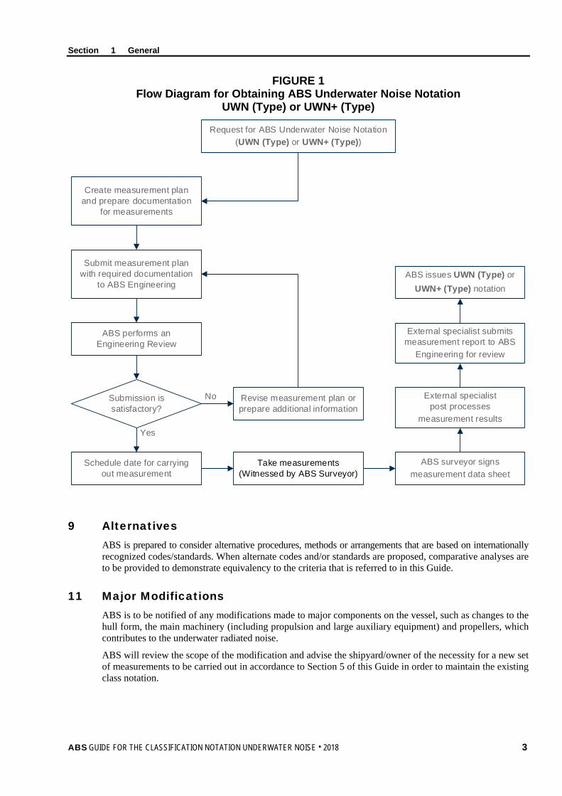
7.3 Process for Obtaining a Notation The flowchart in Section 1, Figure 1 depicts the process for obtaining a UWN (Type) notation or a UWN+ (Type) notation where more stringent requirements are introduced.
The Underwater Noise Measurement Plan, which includes the relevant information and drawings as shown in Section 2, Table 1, is to be submitted to ABS for review before scheduling the underwater noise measurement. The intent of this measurement plan is to serve as a primary means of verification that all the necessary requirements and conditions for carrying out the actual underwater noise measurement during sea trials are satisfied before carrying out the actual measurement. This includes identifying the ABS Recognized External Specialists for Underwater Noise Measurement, who are companies recognized by ABS that are qualified to do underwater noise measurements for the UWN (Type) or UWN+ (Type) notation.
The underwater noise measurement and the data collection process are to be executed by an ABS Recognized Underwater Sound Specialist and witnessed by an ABS Surveyor.
The ABS Recognized External Specialist will post-process the collected measurement data and include the processed results in the final measurement report. The other contents that the measurement report is to include are indicated in Section 2, Table 2. The final measurement report is to be submitted to ABS Engineering for review.
The UWN (Type) or UWN+ (Type) notation may be issued provided that:
• The underwater noise measurement has been carried out according to the measurement plan approved by ABS and the procedures as specified in Section 5
• The resulting signature noise source level from the measurement is within the maximum allowable underwater noise level criteria limits as per Section 3.
2 ABS GUIDE FOR THE CLASSIFICATION NOTATION UNDERWATER NOISE . 2018
Section 1 General
FIGURE 1 Flow Diagram for Obtaining ABS Underwater Noise Notation
UWN (Type) or UWN+ (Type)
Create measurement plan and prepare documentation
for measurements
Submit measurement plan with required documentation
to ABS Engineering
ABS performs an Engineering Review
Submission is satisfactory?
Schedule date for carrying out measurement
Revise measurement plan or prepare additional information
Take measurements (Witnessed by ABS Surveyor)
Request for ABS Underwater Noise Notation (UWN (Type) or UWN+ (Type))
Yes
No
ABS surveyor signs measurement data sheet
External specialist post processes
measurement results
External specialist submits measurement report to ABS
Engineering for review
ABS issues UWN (Type) or UWN+ (Type) notation
9 Alternatives
ABS is prepared to consider alternative procedures, methods or arrangements that are based on internationally recognized codes/standards. When alternate codes and/or standards are proposed, comparative analyses are to be provided to demonstrate equivalency to the criteria that is referred to in this Guide.
11 Major Modifications ABS is to be notified of any modifications made to major components on the vessel, such as changes to the hull form, the main machinery (including propulsion and large auxiliary equipment) and propellers, which contributes to the underwater radiated noise.
ABS will review the scope of the modification and advise the shipyard/owner of the necessity for a new set of measurements to be carried out in accordance to Section 5 of this Guide in order to maintain the existing class notation.
ABS GUIDE FOR THE CLASSIFICATION NOTATION UNDERWATER NOISE . 2018 3

Section 1 General
13 Definitions Acoustic Center. The position on the vessel where it is assumed that all the noise sources are co-located as a single point source. In this Guide, it is assumed to be located halfway between the center of the engine room and the propeller for all test conditions.
Attenuation. The opposite of amplification, which is necessary when voltages to be digitized are beyond the analog-to-digital converter (ADC) range. This form of signal conditioning decreases the input signal amplitude so that the conditioned signal is within the ADC range. Attenuation is typically necessary when measuring voltages that are more than 10 volts.
Background Noise. Noise from all sources (biotic and abiotic) other than the vessel being tested and measured.
Beam Aspect. The direction to either side of the vessel under side.
Broadband. In the context of this Guide, “broadband” refers to sound energy over the one-third octave frequency band. In order to compare broadband measurements, the underwater acoustics community generally report broadband levels in one-third octave frequency bands.
Cavitation Inception Speed: Vessel speed at which a propeller starts to cavitate.
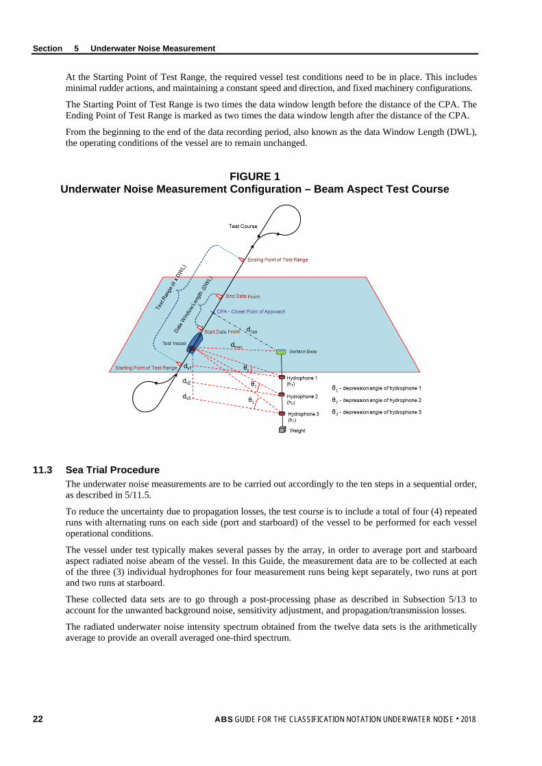
Closest Point of Approach (CPA). The point during a test run where the horizontal distance from the acoustic center of the vessel under test is the closest to the hydrophone(s). This position on the straight line course is referred as the CPA point. The distance at the closest point of approach is defined by the symbol dCPA. See Section 5, Figure 1.
Data Window Length (DWL). The distance between the start data point and the end data point, given as 2 × dCPA × tan(30). See Section 5, Figure 1.
Data Window Period (DWP). The time window the test vessel to travel the data window length (DWL) at a specified test speed (v) given by DWP = DWL/v.
Decibel (dB). A relative unit for the intensity of a sound wave to a reference intensity. In underwater sound, it is expressed using the logarithmic decibel scale referenced to 1 micro-Pascal, as dB re 1 µPa (1.45 × 10⁻¹⁰ psi).
Effective Sound Pressure. The root mean square of the sound pressure of the source over a given interval of time or space.
End Data Point. The position where the data recording is ended when the acoustic center of the test vessel passed this point. It is typically at a distance half DWL past the CPA point. This point is also known as the “Stern CPA”. See Section 5, Figure 1.
Ending Point of Test Range. The ending location of a test run at a distance twice the data window length (DWL) after the CPA point. See Section 5, Figure 1.
Far Field. A region in free space, away from the sound source. In this region, the sound pressure is in phase with the sound particle velocity. In the far field, the direct field radiated by most machinery sources will decay at the rate of 6 dB each time the distance from the source is doubled.
Free Field. A sound field region where sound may propagate freely without any form of obstruction. In practice, a free field can be said to exist if the direct sound is 6 dB, or preferably 10 dB, greater than the reverberant or reflected sound.
Hydrophone. A transducer that produces electric signals in response to water borne acoustic signals. For the purpose of this Guide, “hydrophone” could also refer to the underwater microphone or electro-acoustic transducer.
Narrow Band. The entire frequency range is divided into subsections with equal bandwidth. The bandwidth is usually 1 Hz.
Near Field. A part in the sound field region which is close to a source where the sound pressure is not in phase with the sound particle velocity. In this region, the sound field does not decrease by 6 dB each time the distance from the source is increased (as it does in the far field). The near field is limited to a distance from the source equal to about a wavelength of sound or equal to three times the largest dimension of the sound source (whichever is the larger).
4 ABS GUIDE FOR THE CLASSIFICATION NOTATION UNDERWATER NOISE . 2018
Section 1 General
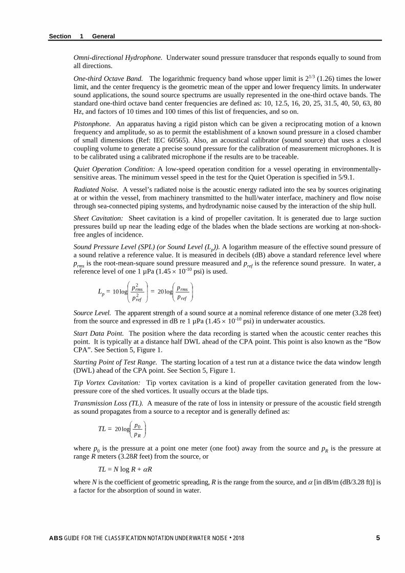
Omni-directional Hydrophone. Underwater sound pressure transducer that responds equally to sound from all directions.
One-third Octave Band. The logarithmic frequency band whose upper limit is 21/3 (1.26) times the lower limit, and the center frequency is the geometric mean of the upper and lower frequency limits. In underwater sound applications, the sound source spectrums are usually represented in the one-third octave bands. The standard one-third octave band center frequencies are defined as: 10, 12.5, 16, 20, 25, 31.5, 40, 50, 63, 80 Hz, and factors of 10 times and 100 times of this list of frequencies, and so on.
Pistonphone. An apparatus having a rigid piston which can be given a reciprocating motion of a known frequency and amplitude, so as to permit the establishment of a known sound pressure in a closed chamber of small dimensions (Ref: IEC 60565). Also, an acoustical calibrator (sound source) that uses a closed coupling volume to generate a precise sound pressure for the calibration of measurement microphones. It is to be calibrated using a calibrated microphone if the results are to be traceable.
Quiet Operation Condition: A low-speed operation condition for a vessel operating in environmentally-sensitive areas. The minimum vessel speed in the test for the Quiet Operation is specified in 5/9.1.
Radiated Noise. A vessel’s radiated noise is the acoustic energy radiated into the sea by sources originating at or within the vessel, from machinery transmitted to the hull/water interface, machinery and flow noise through sea-connected piping systems, and hydrodynamic noise caused by the interaction of the ship hull.
Sheet Cavitation: Sheet cavitation is a kind of propeller cavitation. It is generated due to large suction pressures build up near the leading edge of the blades when the blade sections are working at non-shock-free angles of incidence.
Sound Pressure Level (SPL) (or Sound Level (Lp)). A logarithm measure of the effective sound pressure of a sound relative a reference value. It is measured in decibels (dB) above a standard reference level where prms is the root-mean-square sound pressure measured and pref is the reference sound pressure. In water, a reference level of one 1 µPa (1.45 × 10⁻¹⁰ psi) is used.
Lp =
2
2log10
ref
rms
p
p =
ref
rmspp
log20
Source Level. The apparent strength of a sound source at a nominal reference distance of one meter (3.28 feet) from the source and expressed in dB re 1 µPa (1.45 × 10⁻¹⁰ psi) in underwater acoustics.
Start Data Point. The position where the data recording is started when the acoustic center reaches this point. It is typically at a distance half DWL ahead of the CPA point. This point is also known as the “Bow CPA”. See Section 5, Figure 1.
Starting Point of Test Range. The starting location of a test run at a distance twice the data window length (DWL) ahead of the CPA point. See Section 5, Figure 1.
Tip Vortex Cavitation: Tip vortex cavitation is a kind of propeller cavitation generated from the low-pressure core of the shed vortices. It usually occurs at the blade tips.
Transmission Loss (TL). A measure of the rate of loss in intensity or pressure of the acoustic field strength as sound propagates from a source to a receptor and is generally defined as:
TL =
Rpp0log20
where p0 is the pressure at a point one meter (one foot) away from the source and pR is the pressure at range R meters (3.28R feet) from the source, or
TL = N log R + αR
where N is the coefficient of geometric spreading, R is the range from the source, and α [in dB/m (dB/3.28 ft)] is a factor for the absorption of sound in water.
ABS GUIDE FOR THE CLASSIFICATION NOTATION UNDERWATER NOISE . 2018 5

Section 1 General
15 Abbreviations ADC Analog-to-digital converter
CPA Closest point of approach
DAS Data acquisition system
DWL Data window length
DWP Data window period
EU European Union
GES Good Environmental Status
GPS Global positioning system
ICES International Council for the Exploration of the Sea
IMO International Maritime Organization
MCR Maximum continuous rating
MEPC Marine Environmental Protection Committee
MSFD Marine Strategic Framework Directive
6 ABS GUIDE FOR THE CLASSIFICATION NOTATION UNDERWATER NOISE . 2018

S e c t i o n 2 : D o c u m e n t a t i o n a n d E n g i n e e r i n g R e v i e w
S E C T I O N 2 Documentation and Engineering Review
1 Plans and Documentation for Information The following vessel plans are required to be submitted to the ABS Engineering Office for information:
• General arrangement drawings with vessel main particulars such as overall length, draft, etc.
• Aft end construction drawings
• Machinery/propulsion arrangement drawings
• Machinery information: manufacturer, model, power, RPM, etc.
• Propeller information: manufacturer, model, propeller diameter, propeller pitch, number of blades, speed, power, etc.
3 Engineering Review Before commencing the underwater noise measurement during sea trials, the drawings/documents indicated in Section 2, Table 1 are to be submitted to the ABS Engineering Office for review and approval.
After completing the measurement and result post-processing, the final underwater noise measurement report is to be submitted to ABS Engineering Office for review. The measurement report is to include the contents indicated in Section 2, Table 2.
ABS GUIDE FOR THE CLASSIFICATION NOTATION UNDERWATER NOISE . 2018 7

Section 2 Documentation and Engineering Review
TABLE 1 Underwater Noise Measurement Plan
Type of Document Description Underwater Noise Measurement Plan
A detailed measurement plan developed for the measurement of the underwater sound levels of the vessel prior to the measurement. The plan is to include: 1. Vessel Information and Identification of Participants
a) Vessel information, including vessel’s name, hull number, class number, etc., as well as the vessel’s main dimensions
b) Identification of participants, including person in charge of test, owner representative, shipyard representative, test personnel, and ABS Surveyor
2. Measurement Test Site a) Geographical location, water depth and sea bottom conditions b) Wind speed and sea surface conditions for planned tests c) Weather conditions – Weather conditions are to be predicted based on a reliable weather
forecast site/service 3. Measurement System
a) Hydrophones (number, type and model) and deployment (method and hydrophone depths, including sketches to show the deployment configuration)
b) Distance measurement system c) Calibration plans and current calibration certificates of all measurement instruments d) Detailed information of data acquisition and recording system to be used
4. Sea Test a) Description of measurement procedure b) Test agenda including test schedules, a description of the planned test courses (including
sketches to show the sailing course and identification of the closest point of approach, CPA, and various starting and ending points) and the operating profile which includes the speed, and loading condition of the test vessel for each test course
c) Methods to be used for monitoring the test site environment, checking the vessel operation conditions and other auxiliary measurements
5. Post Processing/Analysis a) Description of post processing and analysis procedures of measured underwater sound data b) Methods for evaluating the measurement uncertainty
8 ABS GUIDE FOR THE CLASSIFICATION NOTATION UNDERWATER NOISE . 2018

Section 2 Documentation and Engineering Review
TABLE 2 Underwater Noise Measurement Report
Type of Document Description Underwater Noise Measurement Report
A vessel-specific underwater sound measurement report containing test information, description of data processing, analysis of measured underwater sound data and compliance evaluation against applicable criteria. The report is to contain, but is not limited to, the following: 1. Introduction
1.1. Objective of Measurement 1.2. Vessel Characteristics
1.2.1. Vessel Particulars 1.2.2. Propulsion Characteristics 1.2.3. Propeller Information
1.3. Underwater Noise Criteria 2. Underwater Noise Measurement
2.1. Measurement Protocol 2.2. Test Period and Site
2.2.1. Location and Time of Measurement 2.2.2. Environmental Conditions
2.3. Instrumentation 2.3.1. Hydrophones and Signal Conditioning
2.3.1.1. Calibration of Hydrophones 2.3.2. Distance Measurement System 2.3.3. Data Acquisition/Processing System
2.3.3.1. Data Sampling Rate 2.4. Test Course and Maneuvering Configuration
2.4.1. Nominal Closest Point of Approach (CPA) 2.4.2. Test Course and Test Runs 2.4.3. Vessel Operating Conditions 2.4.4. Background Noise Measurements 2.4.5. Measurement Procedure
2.5. Other Auxiliary Measurements and Data 2.6. Deviations from Approved Measurement Plan 2.7. Data Sheet with Surveyor Signature
3. Data Processing 3.1. Data Processing Procedure 3.2. Data Quality Assessment 3.3. Background Noise Correction 3.4. Distance Normalization
4. One-third Octave Band Data Analysis 4.1. Results for Each Hydrophone and Each Test Run 4.2. Results for Multiple Hydrophones and Multiple Runs 4.3. Verification against Defined Criteria
5. Narrowband Analysis (if applicable) 6. Summary
ABS GUIDE FOR THE CLASSIFICATION NOTATION UNDERWATER NOISE . 2018 9

S e c t i o n 3 : U n d e r w a t e r N o i s e R e q u i r e m e n t s
S E C T I O N 3 Underwater Noise Requirements
1 General This Section specifies the requirements for the maximum allowable underwater noise limits for specific operating conditions. The type of criteria is assigned with the Type notation as specified in Subsection 1/3.
The frequency range to be evaluated is between 10 Hz to 50,000 Hz for commercial vessels and 10 Hz to 100, 000 Hz for research vessels.
Allowable limits are expressed in one-third octave bands. The unit of the sound pressure level limit is 1 μPa @ 1 m (1.45 × 10⁻¹⁰ psi @ 3.28 ft) in this Guide. It means that the sound pressure level is to be evaluated at 1 m (3.28 ft) away from the acoustic center of the vessel, and the reference sound pressure is 1 μPa (1.45 × 10⁻¹⁰ psi).
Compliance with the Guide is to be verified through underwater sound measurements.
A maximum 3 dB in excess of the criteria curve at a single one-third octave band is acceptable if the overall measured noise level of the vessel can meet the criteria specified in this Guide.
Deviations from the requirements, if they can be justified by analysis, may be accepted upon assessment by ABS (for example, if the narrow band analysis shows the deviations at low frequencies are not related to the underwater noise source, but from disturbance of the measuring device due to sea surface effect or from interference of another object, such as a metrological sound buoy).
3 Underwater Noise (UWN) Requirements for Commercial Vessels The maximum allowable UWN limits for commercial vessels in one-third (1/3) octave bands are specified in Section 3, Figure 1 and the mathematical definition of the limits is indicated in Section 3, Table 1.
FIGURE 1 Allowable UWN Limits for Commercial Vessels
10 ABS GUIDE FOR THE CLASSIFICATION NOTATION UNDERWATER NOISE . 2018
Section 3 Underwater Noise Requirements
TABLE 1 UWN Limits for Commercial Vessels
Frequency Range Criteria, Lp, in dB re 1 µPa @1 m (1.45 × 10⁻¹⁰ psi @ 3.28 ft) Transit Condition Quiet Operation Condition
10 – 100 Hz –1.5 log f + 178.5 –1.5 log f + 170.5 100 – 1 k Hz –6 log f + 187.5 –6 log f + 179.5 1 k – 50 k Hz –10 log f + 199.5 –10 log f + 191.5
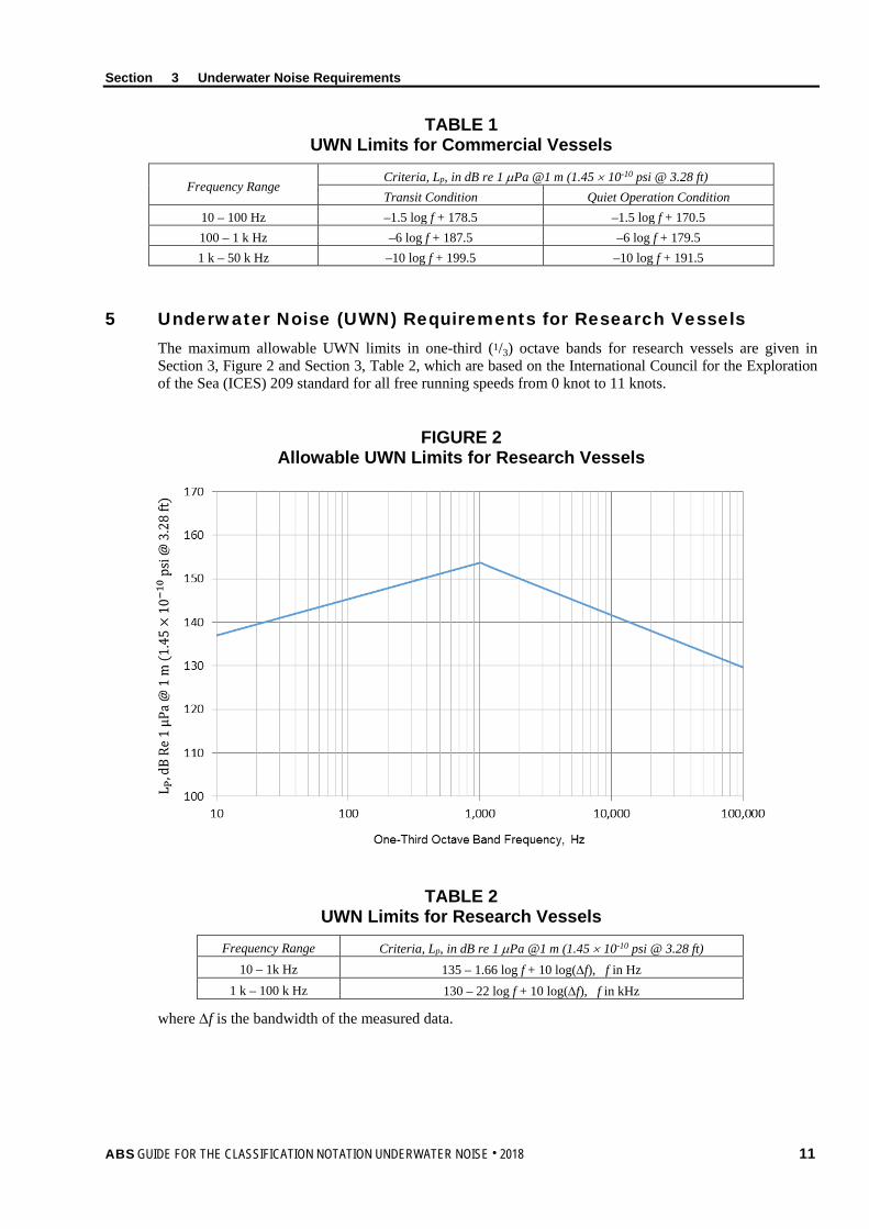
5 Underwater Noise (UWN) Requirements for Research Vessels The maximum allowable UWN limits in one-third (1/3) octave bands for research vessels are given in Section 3, Figure 2 and Section 3, Table 2, which are based on the International Council for the Exploration of the Sea (ICES) 209 standard for all free running speeds from 0 knot to 11 knots.
FIGURE 2 Allowable UWN Limits for Research Vessels
TABLE 2 UWN Limits for Research Vessels
Frequency Range Criteria, Lp, in dB re 1 µPa @1 m (1.45 × 10⁻¹⁰ psi @ 3.28 ft) 10 – 1k Hz 135 – 1.66 log f + 10 log(∆f), f in Hz
1 k – 100 k Hz 130 – 22 log f + 10 log(∆f), f in kHz
where ∆f is the bandwidth of the measured data.
ABS GUIDE FOR THE CLASSIFICATION NOTATION UNDERWATER NOISE . 2018 11
Section 3 Underwater Noise Requirements
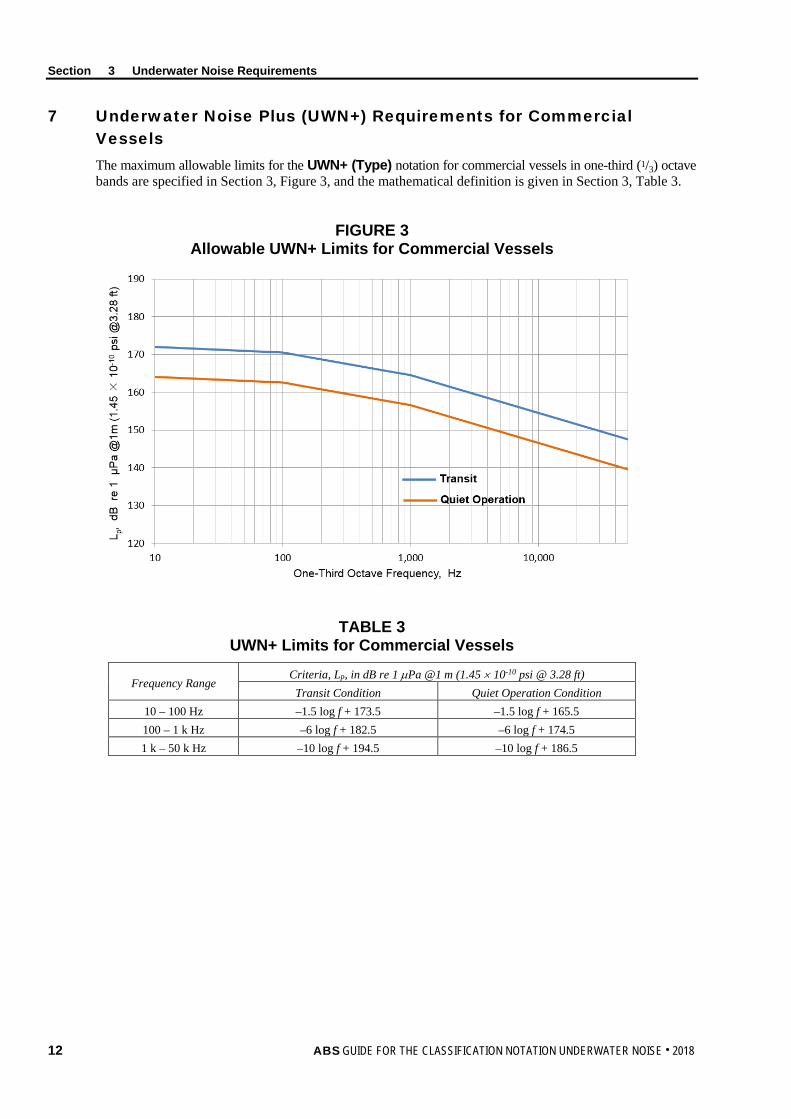
7 Underwater Noise Plus (UWN+) Requirements for Commercial Vessels The maximum allowable limits for the UWN+ (Type) notation for commercial vessels in one-third (1/3) octave bands are specified in Section 3, Figure 3, and the mathematical definition is given in Section 3, Table 3.
FIGURE 3 Allowable UWN+ Limits for Commercial Vessels
TABLE 3 UWN+ Limits for Commercial Vessels
Frequency Range Criteria, Lp, in dB re 1 µPa @1 m (1.45 × 10⁻¹⁰ psi @ 3.28 ft)
Transit Condition Quiet Operation Condition 10 – 100 Hz –1.5 log f + 173.5 –1.5 log f + 165.5 100 – 1 k Hz –6 log f + 182.5 –6 log f + 174.5 1 k – 50 k Hz –10 log f + 194.5 –10 log f + 186.5
12 ABS GUIDE FOR THE CLASSIFICATION NOTATION UNDERWATER NOISE . 2018
S e c t i o n 4 : I n s t r u m e n t a t i o n f o r M e a s u r e m e n t
S E C T I O N 4 Instrumentation for Measurement
1 Introduction This Section outlines the procedures for measurement of the underwater sound emitted by vessels for the assignment of the UWN (Type) or UWN+ (Type) notation.
The key instrumentation components that are used for the measurement of underwater noise include:
i) Hydrophones and their signal conditioning
ii) Sound data acquisition and recording systems
iii) Sound data processing and display systems
“Hydrophone” as used in this Guide refers also to an underwater microphone or electroacoustic transducer.
3 Hydrophones and Signal Conditioning
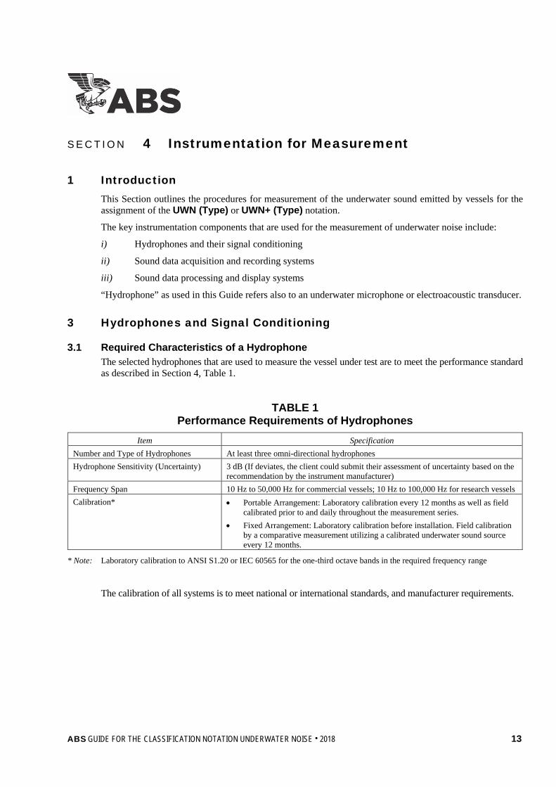
3.1 Required Characteristics of a Hydrophone The selected hydrophones that are used to measure the vessel under test are to meet the performance standard as described in Section 4, Table 1.
TABLE 1 Performance Requirements of Hydrophones
Item Specification Number and Type of Hydrophones At least three omni-directional hydrophones Hydrophone Sensitivity (Uncertainty) 3 dB (If deviates, the client could submit their assessment of uncertainty based on the
recommendation by the instrument manufacturer) Frequency Span 10 Hz to 50,000 Hz for commercial vessels; 10 Hz to 100,000 Hz for research vessels Calibration* • Portable Arrangement: Laboratory calibration every 12 months as well as field
calibrated prior to and daily throughout the measurement series. • Fixed Arrangement: Laboratory calibration before installation. Field calibration
by a comparative measurement utilizing a calibrated underwater sound source every 12 months.
* Note: Laboratory calibration to ANSI S1.20 or IEC 60565 for the one-third octave bands in the required frequency range
The calibration of all systems is to meet national or international standards, and manufacturer requirements.
ABS GUIDE FOR THE CLASSIFICATION NOTATION UNDERWATER NOISE . 2018 13
Section 4 Instrumentation for Measurement
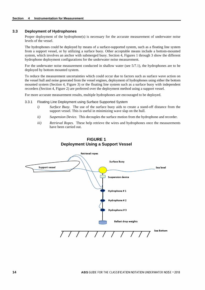
3.3 Deployment of Hydrophones Proper deployment of the hydrophone(s) is necessary for the accurate measurement of underwater noise levels of the vessel.
The hydrophones could be deployed by means of a surface-supported system, such as a floating line system from a support vessel, or by utilizing a surface buoy. Other acceptable means include a bottom-mounted system, which involves an anchor with submerged buoy. Section 4, Figures 1 through 3 show the different hydrophone deployment configurations for the underwater noise measurement.
For the underwater noise measurement conducted in shallow water (see 5/7.1), the hydrophones are to be deployed by bottom mounted system.
To reduce the measurement uncertainties which could occur due to factors such as surface wave action on the vessel hull and noise generated from the vessel engines, deployment of hydrophones using either the bottom mounted system (Section 4, Figure 3) or the floating line system such as a surface buoy with independent recorders (Section 4, Figure 2) are preferred over the deployment method using a support vessel.
For more accurate measurement results, multiple hydrophones are encouraged to be deployed.
3.3.1 Floating Line Deployment using Surface Supported System i) Surface Buoy. The use of the surface buoy aids to create a stand-off distance from the
support vessel. This is useful in minimizing wave slap on the hull.
ii) Suspension Device. This decouples the surface motion from the hydrophone and recorder.
iii) Retrieval Ropes. These help retrieve the wires and hydrophones once the measurements have been carried out.
FIGURE 1 Deployment Using a Support Vessel
14 ABS GUIDE FOR THE CLASSIFICATION NOTATION UNDERWATER NOISE . 2018

Section 4 Instrumentation for Measurement
FIGURE 2 Deployment Using a Surface Buoy with an Independent Recorder
The use of the surface buoy with a recorder allows data to be stored locally. The independent, self-recording receiver platform is contained in the surface buoy, and the radio link allows ease of access to store data.
Radar reflectors are often fitted to the buoys to help avoid damage by possible collisions and help reduce any hazards to ships.
3.3.2 Bottom-mounted System
FIGURE 3 Deployment using Bottom Mounted System (Anchor with Sub Surface Buoy)
Ballast drop weight
Hydrophone # 3
Hydrophone # 2
Hydrophone # 1
Surface Buoy with self- recorder
Sea Bottom
Sea level
Suspension device
Sea level
Hydrophone # 3
Hydrophone # 2
Hydrophone # 1
Anchor
Sea Bottom
Submerged buoy
Cable lines connected to Shore/Vessel on test
ABS GUIDE FOR THE CLASSIFICATION NOTATION UNDERWATER NOISE . 2018 15

Section 4 Instrumentation for Measurement
3.5 Hydrophone(s) Array Deployment Geometry To effectively measure the beam aspect (direction of either side of the vessel with respect to the location of the hydrophones) of the vessel being tested, the arrangement of the three (3) hydrophones is to be such that they hang vertically down in the water column at a depth that results from the 15 degree, 30 degree and 45 degree depression angle between the sea surface and the distance from the acoustic center of the vessel to the hydrophones.
The depth of the hydrophones between the sea surface and its corresponding hydrophone may be determined from the following equation:
d = tan(α) × dCPA
where
dCPA = maximum of 100 m (328 ft) or overall vessel length (corrected with an accuracy of ±10%)
d = depth of the hydrophones (d1, d2, d3) (determined by Pythagorean Theorem), in m (ft)
α = 15°, 30°, 45° (α1, α2, α3)
Other hydrophone deployment methods may be considered provided that the requirements as per Section 4, Table 1 and the arrangement as shown in Section 4, Figure 4 are met upon satisfactory review by ABS.
FIGURE 4 Hydrophone Array Deployment with Respect to Vessel under Test
3.7 Signal Conditioning The types of electronic devices used for signal conditioning are to be carefully considered so that the data acquisition system effectively and accurately records the mechanical signals produced by the hydrophones. These devices include, but are not limited to, the amplifier, filters, sensor excitation, isolation used with the attenuation, and sampling method input configuration.
α3 = 45°
Sea Bottom
Vessel under Test
d1
d2
d3
d CPA Maximum of: 100m (328 ft) OR
Overall ship length
Acoustic center α2 = 30°
α1 = 15°
Sea Surface
Submerged buoy
Anchor
Hydr.2
Hydr.3
Hydr.1
16 ABS GUIDE FOR THE CLASSIFICATION NOTATION UNDERWATER NOISE . 2018

Section 4 Instrumentation for Measurement
5 Data Acquisition and Recording The sound data acquisition system (DAS), which consists of the DAS hardware, sensors and actuators, signal conditioning hardware, and a computer running the DAS software, is to be capable of acquiring, recording, and converting physical parameters such as the analog signals from the hydrophones to digital representations before being manipulated by the digital equipment.
The DAS is also to be able to obtain the position data of the support vessel or the surface buoy, for instance a global positioning system (GPS) or radar. The position of both the vessel under test and the support vessel or surface buoy (whichever is employed as the means for the deployment of the hydrophones) is to be recorded at the time where the measurement is being carried out. Recording systems are to be synchronized to GPS accuracy before deployment and re-checked after retrieval.
The DAS is to have an appropriate sampling rate of at least 2.5 times of the exact center frequency of the highest frequency band.
As appropriate, all the individual equipment/components in the DAS are to be calibrated to a known output level before and after every major deployment or sea trial.
The information regarding the methods and the instrumentation specification (calibration, accuracy, and sensitivity) that are used for data collection, as well as the means to enable accurate data recording, are to be provided.
7 Sound Data Processing and Display System The data processing system (broadband and narrow band) is to be capable of analyzing the sound level to obtain the required data output for the noise assessment as per Subsection 5/13.
The broadband processing of the underwater radiated noise is to cover the one-third octave band frequency range from 10 Hz to 50,000 Hz for commercial vessels and 10 Hz to 100,000 Hz for research vessels. The data processing is to include using the one-third band filters in accordance with Class 1 requirements of IEC 61260.
The narrow band processing is to be in appropriate bandwidths relative to the frequencies. This is usually measured at each 1 Hz frequency. The narrow band processing is to cover a frequency range from 10 Hz to 5000 Hz or higher. Narrow band data can be used for diagnostic purposes as it allows the opportunity to identify specific tones in the noise since the peaks in the measured spectrum can be used to distinguish machinery and systems that are expected to produce identical tones.
Details with regard to the methods, software, and instrumentation used for data analysis of the received acoustic data are to be provided.
ABS GUIDE FOR THE CLASSIFICATION NOTATION UNDERWATER NOISE . 2018 17

S e c t i o n 5 : U n d e r w a t e r N o i s e M e a s u r e m e n t a n d S u r v e y
S E C T I O N 5 Underwater Noise Measurement and Survey
1 General This Section describes the details of the acoustic measurement procedures to be carried out for the measurement of the underwater radiated noise.
1.1 Measurement Protocols The establishment of the underwater noise measurement procedure (measurement plan preparation, test measurement procedures and/or test reporting) used in this Guide are based on the information provided in the following reference documents.
TABLE 1 Current Underwater Noise Measurement Standards
and Other Related Measurement Standards International Recognized Standards
ANSI/ASA S12.64-Part 1, 2009 Quantities and Procedures for Description and Measurement of Underwater Sound from Ships-Part 1: General Requirements
ISO/PAS 17208-1:2012, Part I Acoustics-Quantities and procedures for description and measurement of underwater sound from ships - Part 1: General requirements for measurements in deep water
ICES Cooperative Research Report No. 209 Underwater Noise of Research Vessels, Review and Recommendation
IEC 61260 Electroacoustics – Octave band and fractional-octave band filters
IEC 60565 Underwater acoustics – Hydrophones - Calibration in the frequency range 0,01 Hz to 1 MHz
ANSI/ASA S1.11 Specification for Octave-band and Fractional-octave-band Analog and Digital Filters
ANSI/ASA S1.20 American National Standard Procedures for Calibration of Underwater Electroacoustic Transducers
ISO/IEC Guide 98-3 Uncertainty of Measurement – Part 3 Guide to the Expression of Uncertainty in Measurement
1.3 Measurement Plan The measurement plan is to serve as the principal means of verifying the measurements to be performed to demonstrate compliance with the ABS underwater noise criteria.
The proposed measurement plan is to be submitted to and approved by the ABS Engineering Office prior to performing the underwater noise measurements. Upon review by the ABS Engineering Office, the ship owner or shipyard will then be notified whether the measurement plan has been approved or requires further alteration.
A detailed description of the drawings and information to be included as part of the measurement plan is indicated in Section 2, Table 1.
18 ABS GUIDE FOR THE CLASSIFICATION NOTATION UNDERWATER NOISE . 2018
Section 5 Underwater Noise Measurement
1.5 Background Noise Measurement Background noise is usually a combination of noise from both environmental and man-made sources, and thus is highly variable temporally and spatially.
It is therefore important to determine the background noise level (which is usually present during the measurement at a certain location) so that this can be distinguished and eliminated from the results of the total measured underwater sound pressure level at the end of the test period, allowing for the actual underwater noise measurement to be determined.
1.7 Distance Measurement To measure the underwater radiated noise, it is necessary to acquire the sound pressure measurement at a distance from the sound source and to correct for propagation loss to produce an estimation of the sound pressure level at a reference distance [i.e., 1 m (3.28 ft)].
For the purpose of this Guide, the distance measurement is to be taken between the horizontal distance of the location of the sea surface above the hydrophones and the acoustic center (halfway between the center of the main engine room and the propeller) of the vessel under test, at the CPA.
The accuracy of the distance measurement system shall be within 10% of the distance at the CPA.
1.9 Performance of Underwater Noise Measurement The underwater noise measurement is to be executed by an ABS Recognized External Specialist for Underwater Noise Measurement (see Subsection 5/3).
The ABS Surveyor is to sign the underwater noise measurement data sheet verifying that the measurements were carried out according to the measurement plan approved by ABS.
1.11 Other Auxiliary Measurements and Data Information that may affect the sound propagation during the measurement test period, and therefore accuracy of the final measurement of the underwater noise levels, is recommended to be recorded.
Taking note of the following parameters and information helps to avoid noise contamination with the recording of the underwater noise. This data would also be useful when explaining the deviation (if any) of the final resulting sound signature. Refer to Section 5 of this Guide for more details.
This information includes, but is not limited to, the following:
i) Sea state conditions:
• Seabed composition
• Water column acoustic properties (salinity, water temperature, and density that varies with the water depth to derive the sound speed)
• Tidal deviations in water depth
ii) Weather conditions:
• Rainfall
• Wind direction and speed
• Wave height in relations to the wind speed
iii) Shipping activities near the vicinity:
• Presence of any vessels (their speed, size, and distance from the test site area) operating in the acoustic range/vicinity of the test site
• This could be achieved by means of an Automatic Identification System data
• Presence of any distant noise-generating industrial activity (seismic exploration or offshore construction such as wind farms and hydrocarbon production activities)
iv) Locations of the hydrophones, observation vessel, and recording systems
ABS GUIDE FOR THE CLASSIFICATION NOTATION UNDERWATER NOISE . 2018 19

Section 5 Underwater Noise Measurement
v) Depth of the hydrophones in the water column
vi) Operating conditions of vessels to be tested (speed, draft, machinery configuration, engine output)
vii) Distance of the vessel under test from the harbor
3 ABS Recognized External Specialist for Underwater Noise Measurement The measurement plan is to include information of the ABS Recognized External Specialist for Underwater Noise Measurement who is appointed by the ship owner/shipyard to conduct the underwater noise measurement.
In order to perform underwater noise measurement for ABS survey purposes, the service provider is to become an ABS Recognized External Specialist. The specialist is to provide evidence/documentation demonstrating their capability/knowledge based on their experience and expertise in the field of underwater noise measurements. The documents are to include the specialist’s experiences in conducting the underwater noise measurement to show that it has been carried out in accordance to recognized national, international, or industry standards, as applicable, as indicated in Section 5, Table 1.
A description of the acoustic equipment and facilities used for carrying out the underwater noise measurement, data collection, data analysis, and post processing of the collected measurements data sets for which approval is sought (e.g., calibration, accuracy, sensitivity, etc.) is also to be provided as part of the documentation. This information is to include, but is not limited to, the details of the manufacturer, type and serial number, accuracy, sampling frequency and resolution of the measurement and analysis equipment, and the last maintenance schedule dates. Copies of relevant instrumentation reference calibration certificates, with traceability to a national or international standard are also to be part of the documentation.
The specific requirements for the acoustic equipment are:
• Requirements for the performance and calibration of the hydrophones as indicated in Section 4, Table 1.
• Requirements for the DAS system as indicated in Subsection 4/5.
• Requirements for the data processing system as indicated in Subsection 4/7.
• Requirements for the accuracy of the distance measurement system as indicated in 5/1.7.
Further requirements for becoming an ABS Recognized External Specialist for Underwater Noise Measurement can be obtained from the ABS Programs Office or the local ABS office.
5 Survey The underwater noise measurement and the data collection process are to be executed by an ABS Recognized Underwater Sound Specialist and witnessed by an ABS Surveyor. The test personnel are to complete the Underwater Noise Measurement Data Sheet (Appendix 2) at the time of the survey. Equipment and instrumentation reference calibration certificates, together with the results of the field setup and calibration check, are to be provided to the ABS Surveyor.
7 Test Site Requirements The location of the measurement test site is to be determined by the ship owner, shipyard and approved by ABS before any measurement is carried out. The key factors to consider when selecting a suitable test site are the geographical location and the seasonal weather when carrying out the planned acoustic measurement activity.
Other factors include, but are not limited to, salinity, water temperature, water depth, sea conditions, weather conditions, a safe zone (for the safety and ability of the vessel under test to maneuver taking into account the sea traffic in the vicinity; distance from shore (prevent unwanted reflections), and low background noise (considering the surrounding shipping activities at or near the vicinity of the proposed test site).
20 ABS GUIDE FOR THE CLASSIFICATION NOTATION UNDERWATER NOISE . 2018
Section 5 Underwater Noise Measurement
7.1 Depth of the Water For the underwater noise measurement to be conducted in shallow water (water depth less than 150 m (492 ft)), the minimum water depth requirement (from the keel of the vessel under test) is to be 60 m (196.8 ft) or 0.3v2 m (0.26v2 ft), where v is the vessel speed in m/s (knots), whichever is greater. The sea floor at the test site is to be as flat as possible.
For the underwater noise measurement to be conducted in deep water and in a far-field condition, the minimum water depth requirement (from the keel of the vessel under test) is to be at least 150 m (492 ft) or 1.5 times of the overall vessel length, whichever is greater.
7.3 Weather/Sea Surface Conditions Severe/rough weather and sea surface conditions can result in numerous problems such as increasing the background noise and causing the vessel under test or the observation vessel (if used as the means for deployment of hydrophones) to be unstable and thus require the continuous running of the main engine and its propulsion system to maintain its orientation.
The measurements are to be taken under conditions of Sea State 3 or less with a maximum wind speed of Beaufort number 4.
9 Test Conditions of Vessel
9.1 Operation Condition The measurements are to be carried out as specified in the proposed measurement plan.
The operation condition of Transit or Research Vessels is to be decided by contractual service condition, or with the main and auxiliary engines to run at least 85% of MCR. For vessels fitted with controllable pitch propellers the measurements are to be carried out in the normal operating condition.
The minimum vessel speed in the measurement for Quiet Operation is to be:
vquiet, min = 3.1 + 0.0084 Loa (SI units)
= 6 + 0.005 Loa (US units)
where
vquiet, min = minimum vessel speed in the test for the Quiet Operation, m/s (knots)
Loa = overall length of the vessel, m (ft)
9.3 Loading Condition The measurements are to be carried out under a representative loading condition that is reviewed and approved by ABS. The propeller is to be fully submerged.
9.5 Test Course The vessel is to maintain a straight path on a predetermined course at a constant speed, without excessive rudder actions.
11 Measurement Test Sequence
11.1 General An example of an underwater noise measurement configuration in a beam aspect test course is shown in Section 5, Figure 1.
To achieve the required distance at the CPA between the vessel under test and the hydrophones, the vessel is to maintain a straight line sailing course.
ABS GUIDE FOR THE CLASSIFICATION NOTATION UNDERWATER NOISE . 2018 21
Section 5 Underwater Noise Measurement
At the Starting Point of Test Range, the required vessel test conditions need to be in place. This includes minimal rudder actions, and maintaining a constant speed and direction, and fixed machinery configurations.
The Starting Point of Test Range is two times the data window length before the distance of the CPA. The Ending Point of Test Range is marked as two times the data window length after the distance of the CPA.
From the beginning to the end of the data recording period, also known as the data Window Length (DWL), the operating conditions of the vessel are to remain unchanged.
FIGURE 1 Underwater Noise Measurement Configuration – Beam Aspect Test Course
11.3 Sea Trial Procedure The underwater noise measurements are to be carried out accordingly to the ten steps in a sequential order, as described in 5/11.5.
To reduce the uncertainty due to propagation losses, the test course is to include a total of four (4) repeated runs with alternating runs on each side (port and starboard) of the vessel to be performed for each vessel operational conditions.
The vessel under test typically makes several passes by the array, in order to average port and starboard aspect radiated noise abeam of the vessel. In this Guide, the measurement data are to be collected at each of the three (3) individual hydrophones for four measurement runs being kept separately, two runs at port and two runs at starboard.
These collected data sets are to go through a post-processing phase as described in Subsection 5/13 to account for the unwanted background noise, sensitivity adjustment, and propagation/transmission losses.
The radiated underwater noise intensity spectrum obtained from the twelve data sets is the arithmetically average to provide an overall averaged one-third spectrum.
22 ABS GUIDE FOR THE CLASSIFICATION NOTATION UNDERWATER NOISE . 2018
Section 5 Underwater Noise Measurement
11.5 Underwater Noise Measurement Test Sequence i) The main propulsion and auxiliary machinery conditions are to be set up according to the conditions
as specified in the measurement plan approved by ABS (Section 2, Table 1 and 5/1.1). The same is to be verified by the ABS Surveyor.
ii) The hydrophones and measuring instruments used in the data acquisition system are to be calibrated prior to the underwater noise measurements. The relevant instrumentation reference calibration certificates, together with the results of the field setup and calibration check are to be provided to the ABS Surveyor.
iii) The ABS Recognized External Specialist for Underwater Noise Measurement is to verify that all the measurement systems for carrying out the underwater radiated noise measurement are put in place and are functioning correctly.
iv) At the start and the end of each measurement test run, the background noise measurement is to be carried out and recorded for at least 1 minute with the vessel under test located at the farthest distance or at a distance of at least ≥ 2000 m (approximately 1.08 nautical mile) from the hydrophones, with the same hydrophone deployment and data acquisition methods.
v) During the recording of the background noise measurement, all main engines and generators are to operate only in idle conditions.
vi) After the completion of the background noise measurement, the vessel under test is to proceed to operate at the prescribed operating condition as specified in the approved measurement plan. The operating conditions such as the main and auxiliary engine output, vessel speed, propeller RPM and nominal pitch, and loading condition are to be recorded accordingly.
vii) Before the acoustic center of the vessel reaches the Starting Point of Test Range, the desired operating conditions of the vessel under test are to be achieved. Between the Starting Point of Test Range and the Ending Point of Test Range, the direction and vessel operating conditions are to remain the same.
viii) The data recording of the test measurement for the radiated underwater noise (where the mechanical output signal of the hydrophones is sent to the data acquisition system) is only to commence when the position of the acoustic center of the vessel under test reaches the start data point (beginning of the data window period) and is to terminate when the acoustic center of the vessel under test reaches the end data point (end of the data window period) as shown in Section 5, Figure 1.
ix) Distance measurements are to be recorded for the vessel under test. These include the distance at the closest point of approach (dCPA), horizontal distance from the acoustic center of the vessel to each hydrophone and the vertical distance between the depth of each hydrophone and the sea surface.
x) The vessel under test is to make a “Williamson Turn” at the Ending Point of Test Range, where the vessel will maneuver and prepare for the next set of runs on the alternate side of the vessel repeating the measurement procedure vi) to ix).
A complete test course requires the vessel under test to perform two (2) repeated runs (with alternating approach) each on the port and starboard side of the vessel under the same operating conditions.
13 Processing and Analysis of Measured Data The measured underwater radiated sound pressure level from the vessel under test is to undergo a post-processing phase to account for background noise adjustment, sensitivity adjustment and distance correction.
The underwater radiated sound pressure level, which is collected during the data window period (DWP), is to be filtered and applied with the root mean square linear averaged [expressed in terms of dB re 1 µPa (1.45 × 10⁻¹⁰ psi)] in one-third octave bands, as well as in the narrow band spectrum for each run of the measurement.
ABS GUIDE FOR THE CLASSIFICATION NOTATION UNDERWATER NOISE . 2018 23

Section 5 Underwater Noise Measurement
13.1 Background Noise Correction A set of background noise data is to be collected at the beginning and at the end of each measurement run. This is to enable the comparison of the sound pressure level radiated from the vessel under test to the background noise level during the period of the measurement test.
The background noise collected during the data window period (DWP) is to be filtered and applied with the root mean square linear averaged (expressed in terms of dB re.1 µPa (1.45 × 10⁻¹⁰ psi) in one-third octave bands as well as in the narrow band spectrum each run of the measurement.
The signal-plus-noise-to-noise ratio, ∆L, for each 1/3 octave band is calculated as shown in Equation 1.
Depending on the output of the signal-plus-noise-to-noise ratio, the following conditions in Section 5, Table 2 will apply according for the measured underwater sound pressure level of the vessel under test.
TABLE 2 Signal-Plus-Noise-to-Noise Ratio Conditions
Signal-Plus-Noise-to-Noise Ratio Conditions
∆L > 10 dB No background noise correction would be required. See Equation 2
3 dB ≤ ∆L ≤ 10 dB Background noise correction is to be applied to the measured underwater sound pressure level. See Equation 3
∆L < 3 dB The measured underwater sound pressure level results might be considered as an invalid data ABS would evaluate and consider the validity of the data depending on a case-by-case basis.
Signal-plus-noise-to-noise ratio, ∆L ∆L = Lps+n – Lpn =
+2
2log10
n
ns
pp ...................................... (1)
For ∆L > 10 dB Lp = Lps+n ........................................................................... (2)
For 3 dB ≤ ∆L ≤ 10 dB pL′ = ( ) ( )[ ]1010 1010log10 pnnps LL −+ .................................... (3)
where
∆L = signal-plus-noise-to-noise ratio
ps+n = total underwater sound pressure received at the hydrophones, in µPa (psi). This includes both the underwater radiated sound from the vessel under test and the unwanted background noise.
pn = sound pressure of the background noise received at the hydrophone, in µPa (psi)
Lps+n = sound pressure level of the vessel under test for each run, in dB
Lpn = background sound pressure level taken with the vessel under test being at a distance of 2 km (6560 ft) away from the hydrophones, in dB
Lp = underwater sound pressure level that do not require background noise correction, in dB re 1µPa (1.45 × 10⁻¹⁰ psi)
pL′ = underwater sound pressure level, adjusted to include the background noise correction, in dB re 1µPa (1.45 × 10⁻¹⁰ psi)
13.3 Bottom Effect Correction If the distance between the hydrophone and the bottom is less than 0.2 m (0.66 ft), a 5 dB reduction to the underwater sound pressure level can be made to correct for the sound reflection from the sea bottom.
24 ABS GUIDE FOR THE CLASSIFICATION NOTATION UNDERWATER NOISE . 2018
Section 5 Underwater Noise Measurement
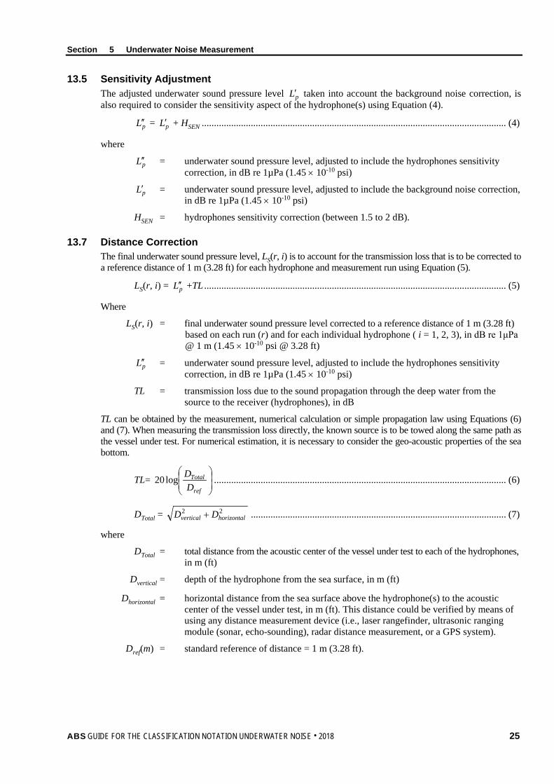
13.5 Sensitivity Adjustment The adjusted underwater sound pressure level pL′ taken into account the background noise correction, is also required to consider the sensitivity aspect of the hydrophone(s) using Equation (4).
pL ′′ = pL′ + HSEN ............................................................................................................................ (4)
where
pL ′′ = underwater sound pressure level, adjusted to include the hydrophones sensitivity correction, in dB re 1µPa (1.45 × 10⁻¹⁰ psi)
pL′ = underwater sound pressure level, adjusted to include the background noise correction, in dB re 1µPa (1.45 × 10⁻¹⁰ psi)
HSEN = hydrophones sensitivity correction (between 1.5 to 2 dB).
13.7 Distance Correction The final underwater sound pressure level, LS(r, i) is to account for the transmission loss that is to be corrected to a reference distance of 1 m (3.28 ft) for each hydrophone and measurement run using Equation (5).
LS(r, i) = pL ′′ +TL ........................................................................................................................... (5)
Where
LS(r, i) = final underwater sound pressure level corrected to a reference distance of 1 m (3.28 ft) based on each run (r) and for each individual hydrophone ( i = 1, 2, 3), in dB re 1μPa @ 1 m (1.45 × 10⁻¹⁰ psi @ 3.28 ft)
pL ′′ = underwater sound pressure level, adjusted to include the hydrophones sensitivity correction, in dB re 1µPa (1.45 × 10⁻¹⁰ psi)
TL = transmission loss due to the sound propagation through the deep water from the source to the receiver (hydrophones), in dB
TL can be obtained by the measurement, numerical calculation or simple propagation law using Equations (6) and (7). When measuring the transmission loss directly, the known source is to be towed along the same path as the vessel under test. For numerical estimation, it is necessary to consider the geo-acoustic properties of the sea bottom.
TL=
ref
Total
DDlog20 ....................................................................................................................... (6)
DTotal = 22horizontalvertical DD + ........................................................................................................ (7)
where
DTotal = total distance from the acoustic center of the vessel under test to each of the hydrophones, in m (ft)
Dvertical = depth of the hydrophone from the sea surface, in m (ft)
Dhorizontal = horizontal distance from the sea surface above the hydrophone(s) to the acoustic center of the vessel under test, in m (ft). This distance could be verified by means of using any distance measurement device (i.e., laser rangefinder, ultrasonic ranging module (sonar, echo-sounding), radar distance measurement, or a GPS system).
Dref(m) = standard reference of distance = 1 m (3.28 ft).
ABS GUIDE FOR THE CLASSIFICATION NOTATION UNDERWATER NOISE . 2018 25
Section 5 Underwater Noise Measurement
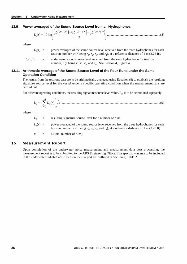
13.9 Power-averaged of the Sound Source Level from all Hydrophones
LS(r) = ( ) ( ) ( )
++3
101010log1010)3,(10)2,(10)1,( rLrLrL SSS
................................................................ (8)
where
LS(r) = power averaged of the sound source level received from the three hydrophones for each test run number, r (r being r1, r2, r3, and r4), at a reference distance of 1 m (3.28 ft).
LS(r, i) = underwater sound source level received from the each hydrophone for test run number, r (r being r1, r2, r3, and r4). See Section 4, Figure 4.
13.11 Arithmetic Average of the Sound Source Level of the Four Runs under the Same Operation Condition The results from the test runs data are to be arithmetically averaged using Equation (8) to establish the resulting signature source level for the vessel under a specific operating condition when the measurement runs are carried out.
For different operating conditions, the resulting signature source level value, LS, is to be determined separately.
LS = nrLkr
rS
∑=
=1
)( ....................................................................................................................... (9)
where
LS = resulting signature source level for n number of runs
LS(r) = power averaged of the sound source level received from the three hydrophones for each test run number, r (r being r1, r2, r3, and r4), at a reference distance of 1 m (3.28 ft).
n = 4 (total number of runs).
15 Measurement Report Upon completion of the underwater noise measurement and measurement data post processing, the measurement report is to be submitted to the ABS Engineering Office. The specific contents to be included in the underwater radiated noise measurement report are outlined in Section 2, Table 2.
26 ABS GUIDE FOR THE CLASSIFICATION NOTATION UNDERWATER NOISE . 2018
A p p e n d i x 1 : U n d e r w a t e r N o i s e C o n t r o l
A P P E N D I X 1 Underwater Noise Control
1 Introduction A good rule of underwater noise control is to use equipment with lower noise and/or vibration level. Propellers and machinery equipment are two dominant underwater noise sources. The noise control of the two sources can effectively reduce the underwater noise emitted by vessels. This Section introduces some basic approaches for the selection, design, installation and maintenance of quieter propellers or machinery equipment.
3 Propeller Noise Control Propeller cavitation can generate excessive noise. Therefore, an important noise control approach is to operate a vessel below the propeller cavitation inception speed. A well-designed propeller can have a relatively high cavitation inception speed, which makes it less susceptible to cavitation.
In order for a propeller to have a good acoustic performance, it is also important to have a sufficient clearance between the blade tips and the hull of the vessel, and have smooth inflows of water into the propeller. In addition, cleaning and maintenance of propeller are critical to underwater noise control. Propellers with dings, missing sections, barnacles, etc., can be significantly louder than a clean propeller in its original form.
The following are some general design guidelines for quieter propellers:
• Increasing propeller diameter and reducing rotation rate can generally increase the cavitation inception speed
• Increasing the number of blades can delay inception of tip vortex cavitation and thicker blade sections can be used to delay the inception of sheet cavitation
• A well-designed skewed propeller shape can normally have a better acoustic performance
• Adjusting blade pitch distribution to unload tip can reduce cavitation
5 Machinery Equipment Noise Control When selecting quieter machinery equipment, the following guideline can be used:
• Rotating equipment is usually quieter than reciprocating equipment
• Drip-proof electric motors are usually quieter than totally enclosed fan-cooled motors
• Pumps operating at their most efficient design point are less noisy than those operating off design
• Generally, gas turbines are quieter than diesel engines and produce lower vibration levels
Once a piece of machinery is selected, it needs to be properly installed on a foundation with enough stiffness. The natural frequency of the foundation should not coincide with the excitation frequency of the equipment. For machinery equipment with a higher vibration level, it is recommended to install isolations or resilient mounting system between the equipment and foundation to reduce the structure-borne noise caused by machinery vibration.
ABS GUIDE FOR THE CLASSIFICATION NOTATION UNDERWATER NOISE . 2018 27
A p p e n d i x 2 : U n d e r w a t e r N o i s e M e a s u r e m e n t s D a t a S h e e t
A P P E N D I X 2 Underwater Noise Measurements Data Sheet
28 ABS GUIDE FOR THE CLASSIFICATION NOTATION UNDERWATER NOISE . 2018

Underwater Noise Measurements Data Sheet Ship’s Name Owner Representative
Hull Number Yard Representative
Ship Owner Test Specialist
Yard Person in charge of test
Class Surveyor
Test Schedule
Vessel Particulars
Ship Particulars Main Engine Propulsor Auxiliary Engines
Loa B D Displacement Type Type Type
Design No. of Main Engines
No. of Blades No. of Aux. Engines
Pre-test --- --- MCR Diameter Power
Post Test --- --- Speed (rpm) Speed (rpm)
Loading Condition Mounting Mounting
Test Conditions
Comments or Further Information Location and Environmental Conditions Measurement Systems
Location Acoustic Measurement System (3 hydrophones)
Longitude/ Latitude
Hydrophone Type
Water column acoustic properties
Hydrophone Depth (vertical at equally depths of 15°, 30° and 45° angle)
Sea State (< sea state 3)
Distance Measurement System (GPS, optical, acoustical, radar, etc.)
Wind Speed (≤ 20 knots)
Nominal CPA Distance (dcpa) (≥ 100 m or Loa)
Water Depth Hydrophone calibration condition
Appendix 2
Underw
ater Noise M
easurements D
ata Sheet
AB
S GUIDE FOR THE CLASSIFICATION NOTATION UNDERW
ATER NOISE . 2018 29

Rain
Vessel Traffic
Test Log
Run # Record ID Heading Time
Beginning/End
Duration GPS Speed
Log Speed
Engine Speed
Horz. Range at Bow CPA
Nominal CPA (dcpa)
Horz. Range at Stern CPA
Wave (Dir. & Height)
Wind (Dir. & Speed)
Background Noise Measurement 1, before test
BN1
1 Beam Port
2 Beam Stb
Background Noise Measurement 1, after test
Background Noise Measurement 2, before test
BN2
3 Beam Port
4 Beam Stb
Background Noise Measurement 2, after test
Background Noise Measurement 3, before test
BN3
Background Noise Measurement 3, after test
Background Noise Measurement 4, before test
BN4
Ship owner/ Yard:
ABS: Test Specialist:
Name Signature Date Name Signature Date
Appendix 2
Underw
ater Noise M
easurements D
ata Sheet
30 A
BS
GUIDE FOR THE CLASSIFICATION NOTATION UNDERWATER NOISE . 2018

A p p e n d i x 3 : R e f e r e n c e s
A P P E N D I X 3 References
1. IMO MEPC 57/INF.4, 2007, Shipping Noise and Marine Mammals, Submitted by the United States to the Marine Environment Protection Committee, 57th Session
2. IMO MEPC.1/Circ.833, 2014, Guidelines for the Reduction of Underwater Noise from Commercial Shipping to Address Adverse Impacts on Marine Life
3. EC 2010, Commission Decision of 1 September 2010 on criteria and methodological standards on good environmental status of marine waters (2010/477/EC), Official Journal of the European Union
4. EU Directive 2008/56/EC of 17 June 2008, Establishing a framework for community action in the field of marine environmental policy (Marine Strategy Framework Directive), Official Journal of the European Union
5. ANSI/ASA S12.64-2009, Quantities and Procedures for Description and Measurement of Underwater Sound from Ships, Part 1: General Requirements
6. ISO/PAS 17208-1-:2012 – Acoustics – Quantities and procedures for description and measurement of underwater sound from ships – Part 1: General requirements for measurements in deep water
7. ICES Cooperative Research Report No. 209, May 1995, Underwater Noise of Research Vessels, Review and Recommendation, R.B. Mitson
8. World Meteorological Organization-No. 306 (1995). International Codes Vol I.1 Part A Alphanumeric Codes. Geneva, Switzerland
9. International Electrotechnical Commission. (2014). Electroacoustics – Octave band and fractional – octave band filters (International Standard IEC 61260) (Note: Reference by ANSI)
10. International Electrotechnical Commission. (2006). Underwater acoustics – Hydrophones – Calibration in the frequency range 0,01 Hz to 1 MHz (International Standard IEC 60565)(Note: Reference by ANSI)
11. ANSI/ASA S1.11 (2014), Specification for Octave-band and Fractional-octave-band Analog and Digital Filters
12. ANSI/ASA S1.20 (2012), Procedures for Calibration of Underwater Electroacoustic Transducers (Note: Reference by ANSI)
13. ISO/IEC Guide 98-3 (2008), Uncertainty of Measurement – Part 3 Guide to the Expression of Uncertainty in Measurement
14. OSPAR Commission (2009), Overview of the Impacts of Anthropogenic Underwater Sound In the marine Environment, Publication number 441/2009
15. OSPAR Commission (2009), Assessment of Environmental Impact of Underwater Noise, Publication number 436/2009
16. NPL Good Practice Guide No. 133 (2014), Underwater Noise Measurement
17. EMEC report (2012), Acoustic Noise Measurement Methodology for the Billia Croo Wave Energy Test Site
18. EMEC report (2014), Underwater Acoustic Monitoring at Wave and Tidal Energy Sites: Guidance Notes for Regulators
19. DSTL Naval Systems (2011), Quality Assurance Assessment of a Study into Underwater Radiated Noise From Marine Aggregate Dredging Operations For the Marine Aggregate Levy Sustainability Fund
20. David L. Bradley and Richard Stern, 2008, Underwater Sound and the Marine Mammal Acoustic Environment, A Guide to Fundamental Principles
ABS GUIDE FOR THE CLASSIFICATION NOTATION UNDERWATER NOISE . 2018 31

Appendix 3 References
21. Megan F. McKenna, 2012, Underwater Radiated Noise from Modern Commercial Ships
22. Brown, N., “Cavitation Noise Problems and Solutions,” International Symposium on Shipboard Acoustics, J. H. Janssen (ed.), Elsiver Scientific Publications, Amsterdam, 1976.
23. R. W. Fischer, C. B. Burroughs and D. L. Nelson, Design guide for shipboard airborne noise control, New York: The Society of Naval Architects and Marine Engineers, 1983.
32 ABS GUIDE FOR THE CLASSIFICATION NOTATION UNDERWATER NOISE . 2018