umtri - Deep Blue - University of Michigan
71
STEERING WHEEL ABDOMINAL IMPACT TRAUMA Guy S. Nusholtz Contract Number: MVMA 6 13 1 Final Technical Report July 1986 UMTRI The University of Michigan Transportation Research Institute
Transcript of umtri - Deep Blue - University of Michigan

STEERING WHEEL ABDOMINAL IMPACT TRAUMA
Guy S. Nusholtz
Contract Number: MVMA 6 13 1
Final Technical Report July 1986
UMTRI The University of Michigan Transportation Research Institute

Tocbaical R.port Docurmtuti'k Page
1. R-rt No.
UMTRI-86-38 2. G o v e m m t Aceoasim No. 3. Rocipimt's Cotolog No.
4. Tit lo ond Subtitls
"Steeri ng Wheel Abdominal Impact Trauma
7. Authda)
Guy S. Nushol tz 9. Performing Orgmirmtim N m o m d Addrosa
Biosciences Division Transportation Research Ins t i tu te The University of Michigan 7qQLBaXtpr Rrl Ann Arhnr. MT 48109
12. Sponsotin( Agoncy N r e m d ~; ldrosa
Motor Vehicle Manufacturers' Association 300 New Center Bui 1 ding Detroit, Michigan 48202
15. Suppi-twy Motor
5. Report Dot* July, 1986
6. Potforming Orgonixition cob UMTRI
8. Perfoming 0rgmizati.n Report No.
UMTRI 86-38 10. WorL Unit No. (TRAIS)
11. bn t roc * OI Gront NO.
61 31 13. TYPO of Roport and Period Covered
Fi nal 1985-1 986
14. h n s o r i n g Agency Code
Dynamic biomechanics experimental impact test ing protocol
16. Abatroct
This report outlines the biomechanics impact test ing protocol that was developed for simulation of steering wheel assembly abdominal trauma using the unembalmed human cadaver surrogate. A ser ies of non-injurious m u 1 tip1 e thoraco-abdoniinal impacts plus a single injurious abdominal impact to one cadaver uti 1 i z i ng a special l y crafted steering wheel assembly, n o t representati ve of any manufactured s teer i ng wheel assembly, using th i s protocol i s presented. The steering wheel assembly was designed by and obtained from the General Motors Research Labora- to r ies .
17. K q Wwda
impact biomechatii cs thoraco-abdominal trauma steering wheel assembly human cadaver surrogate
18. Distr ihrt im Stotsmmt
19. keurit). Clus i f . (of this roprt)
- a. k w r i t y Clossil. (of W a -1 21. No. of Pogo.
6 9
22. Pnco

STEERING WHEEL ABDOMINAL IMPACT TRAUMA
MVMA Project No. 613 1 - Final Report
Project Director: Guy S. Nusholtz
Overview
Project No. 6131 was a continuation of a project funded in fiscal year 1984-85
concerning abdominal trauma caused by impact with a steering wheel assembly. The
precursor project evaluated previous dynamic biomechanics research conducted at UMTRI
and elsewhere as part of the task of designing a protocol to conduct simulations of steering
wheel assembly impacts using the unembalmed human cadaver as a surrogate for the live
response. That data-base included observations made upon six different human surrogates:
1. anesthetized canines, 2. postmortem canines, 3. anesthetized Rhesus, 4. postmortem
Rhesus, 5. anesthetized porcine, and 6. the unembalmed repressurized human cadaver
(1,2,4)'. The detailed methods and results of those research projects and the comparison
were reported at the 29th Stapp Car Crash Conference (1,2,4). These data indicated the need
to investigate further the kinematic variables involved in steering wheel assembly impact--
especially that of victim contact region. This report outlines the impact testing protocol that
was developed for simulation of steering wheel assembly abdominal trauma using the
unembalmed human cadaver surrogate and a specially crafted steering wheel assembly
model designed by and obtained from the General Motors Research Laboratories (GMRL).
The specially crafted steering wheel assembly model is a physical one, not directly related to
any steering wheel assembly being produced by the automotive industry. In addition, John
- - - - -
1 Identifies references located at the end of the report.

Horsch and Ian Lau of GMRL were consulted on how best to design the UMTRI impact
testing protocol to complement work at GM aimed at improving anthropomorphic test
device (i.e. safety dummy) simulation of abdominal response. The protocol that was
developed was followed for one unembalmed human cadaver steering wheel assembly
thoraco-abdominal impact test, and evaluated. The analysis of the significant kinematic
parameters investigated (e.g. subject contact region, repeatability, and pulmonary
repressurization) indicated that further dynamic biomechanics laboratory simulations are
justified and necessary.
METHODOLOGY
The research program consisted of six series of dynamic thoraco-abdominal impacts
to an unembalmed human cadaver. Eighteen impacts (non-destructive) were conducted at
2.6 4 s and a nineteenth (destructive) was conducted at 10 4 s . The test protocol is attached
as Appendix A. The kinematic parameters investigated were steering rim force, velocity,
subject contact region, repeatability, and pulmonary repressurization. In addition, velocity
and dsplacement at thoracic vertebra T12 were derived from high-speed photogrammetry
and digital smngpots.
The impacting device was the UMTRI pneumatic ballistic pendulum. The striker
was a steering wheel assembly model crafted by GMRL, Subject instrumentation included a
triaxial accelerometer rigidly affixed to thoracic vertebra T12, a stringpot transducer
attached to the same location, and a pressure transducer inserted into the pulmonary
repressurization tube (within the trachea). Structure instrumentation included a stringpot
transducer on the pendulum and a triaxial accelerometer mounted on the steering column.
The subject was suspended from a ceiling hoist by means of a head and parachute
harness system. The tests were controlled by an electronic timing device. The gross
motion was documented on high-speed film.
The post-test investigation included measunment of the subjecz's con body
temperanxe. Induced damage was assessed during a gross pathological investigation.
The analyrical results an presented in tht form of time-histaries of the kinematic
variables, mechanical m f e r impedance, and transfer f ' t i o n s between paired kinematic
variables.
Impact Test Matrix - Eightcen low-velocity (2.6 d s ) nondamaging irnpaca, plus one high-
velocity (10 m/s) damaging impact formed the dynamic biomechanics test matrix The
parametas wen divided into chronological test groups as follows:
Series A: Abdominal contact region, u a n p r e s s ~ low velocity.
Ttss: 86MOQlA-D
Series B: Rib 10 contact region, umcprrsslaiztd, low velocity.
Tests: 86M002A-C -.
Serits C; Substmale contact reion, unrcpntrircQ low velocity.
Series D:
Series E:
Series F:
Tests: 86M003A-C
Subsumale contact region, npressuriztd pulmonary s y s m low
velocity.
Tests: 86M004A-E
Abdominal contact ngion, umqmssarized, low velocity.
Tests: 86M005A-C
Abdominal contact region, u n r c p ~ e e d , high vdocity.
Test: 86M006

Pneumatic Ballistic Pendulum Impact Device - The impact device consisted of a 20 kg
ballistic pendulum mechanically coupled to the UMTRI pneumatic impact device (i.e. the
cannon), which was used as the energy source. The cannon consisted of an air reservoir and
a ground and honed cylinder with a carefully fitted metal-alloy piston. The piston was
connected to the ballistic pendulum with a nylon cable. The piston was propelled by
compressed air from the air reservoir chamber through the cylinder, accelerating the ballistic
pendulum to become a free-traveling impactor. The pendulum striker was fitted with an
inertia-compensated load cell, which was rigidly mounted at the base of the specially-crafted
steering wheel assembly model column.
GMRL Steering Wheel Assembly Model - The physical model was a mechanical
simulation of the lower rim of a steering wheel assembly. It was not directly related to any
steering wheel assembly being manufactured by the automotive industry. A triaxial
accelerometer was rigidly mounted to the hub of the steering wheel assembly model.
Subject Handling - The unembalmed cadaver used in the dynamic biomechanics testing
was obtained from the University of Michigan Department of Anatomy and stored in a
cooler at 4°C. The cadaver was x-rayed as a part of the structural screening for existing
anomalies, surgical implants, and damage. The subject was then measured using standard
anthropometric techniques. Next the cadaver was sanitarily and surgically prepared, dressed
in vinyl and cotton clothing, and fitted with the head and parachute harnesses. In the impact
laboratory, the accelerometers, pressure transducers, and photo targets were attached. The
subject was placed in a seated position on a mobile, adjustable-height table covered with
friction-reducing clear plastic sheets, and supported by the head and parachute harnesses via
a ceiling hoist. The steering wheel assembly was positioned for the contact-region

controlled impact. The subject received multiple impacts, and was examined post-test for
damage. The post-test examination included a gross pathological investigation.
Pulmonary Repressurization - A tracheotomy was performed to place a tube in the trachea
which was connected to a compressed air reservoir, so that the pulmonary system could be
repressurized to 15 mrn Hg. An Endevco pressure transducer was inserted into the tracheal
tube to measure the dynamic pulmonary pressure at initial repressurization and during the
changes in pressure that occurred throughout the impact. The tracheal tube was fitted with a
valve so that direct communication between the lungs and the external air was possible just
before impact.
Acceleration Measurement - A Kistler triaxial accelerometer, affixed to thoracic vertebra
T12, documented the kinematic response of the subject's spine, To surgically implant a
rigid support for the max an incision was made over the thoracic vertebra T12 of the cadaver
so that lateral supports for the accelerometer mount were anchored on the lamina bilaterally.
Acrylic was applied under and around the mount to ensure rigidity.
Stringpot Measurement - Displacement of the subject was determined by interpreting the
linear displacement of a steel cable attached to the thoracic vertebra T12. The cable was
connected to a gear that rotated according to the subject's movements during the impact test.
The revolutions of the gear were counted by a magnetic probe pickup, and the distance that
the subject traveled during the impact was calculated from the probe measurement.
Gross Body Motion - The gross body motion of the subject during impact was recorded on
high-speed film at 500 frames per second. The camera was a Hycam, positioned to film a
lateral view of the impact.

METHODS OF ANALYSIS
The techniques used to analyze the results are outlined below. Additional
information can be found elsewhere (1-3).
Force Time-History Determination - In general the force time-histories were unimodal
with a single maximum, smoothly rising, peaking and then falling. Force duration was
determined using a boundary defining and least-squares line-fitting technique. This
procedure began by determining the peak, or the first peak in the case of a bimodal
waveform. Next, the left half of the pulse, defined from the point where the pulse started to
rise to the time of peak, was least-squares fitted with a straight line. This rise line
intersected the time axis at a point which was taken as the formal beginning of the pulse. A
similar procedure was followed for the right half of the pulse, i.e. a least-squares line was
fitted to the fall section of the pulse. The fall-section of the pulse was defined from the peak
to the point where the pulse minimum occurred. The point where this line intersected the
time axis became the formal end of the pulse.
Principal Direction Frame Field - One method of determining the principal direction of
motion is constructing the Principal Direction Triad by determining the direction of the
acceleration vector in the moving frame of the triaxial accelerometer cluster and then
describing the transformation necessary to obtain a new moving frame that would have one
of its axes in the principal direction. A single point in time at which the acceleration was a
maximum is chosen to define the directional cosines for transforming from the triax frame to
a new frame in such a way that the resultant acceleration vector (AR) and the "principal"
unit vector (Al) are co-directional. This orthogonal transformation was used to construct a
new frame rigidly fixed to the triax, but differing from the original by an initial rotation.

Then, a comparison between the magnitude of the principal direction and the resultant
acceleration was performed.
Transfer Function Analysis - For blunt impacts occurring within dynamic biomechanical
systems using human surrogates, the relationship between a transducer time-history at a
given point and at another given point can be described in the frequency domain through the
use of a transfer function. A Fast Fourier Transformation of simultaneously monitored time-
histories from any two points in the system can be used to define a frequency response
function relating the two points. In a case relating a force to a pressure, a transformation of
the form:
x(io) = F[F(t)l/F[P(t)l
can be obtained from the transformed quantities F[F(t)] and F[P(t)] respectively, the Fourier
transforms of the impact force time-history and the pressure time-history, and where o is the
given frequency and i implies the complex domain.
Mechanical Impedance - A special transfer function that relates impact force to the
resulting velocity of a point is known as "mechanical transfer impedance." The transfer
function is a complex-valued function which will be simply presented in terms of its
magnitude and phase angle. This function is defined:
Z(i@> = (o)F[F(t)/FCA(t)l
where is the chosen frequency and F[F(t)] and F[A(t)] are, respectively, the Fourier
transforms of the impact force and acceleration at the point of interest. Mechanical transfer
impedance is also defined as the ratio between the simple harmonic driving force and the
corresponding velocity at the point of interest (3).

RESULTS
The significant results are presented in summary form. Table 1 includes peak force,
force duration, and velocity. The high velocity (10 m/s) steering wheel assembly impact
damages were: contusion striping on both lungs, small laceration on superior heart, rib R1R
fractured at sternum, ribs fractured twice (R7R, R7L, R8R, R8L, R9R, R9L, RlOR, RlOL),
rupture through superior liver, contused right kidney, and lacerated transverse intestines.
Time-histories of selected variables are included in Appendix B.
DISCUSSION
The results cover only one test subject, and entail an extremely limited testing matrix.
The goal of the testing was to evaluate the thoraco-abdominal impact test protocol that had
been designed. All results of the thoraco-abdominal steering wheel assembly impact testing
performed as part of the evaluation of the designed protocol should be considered
preliminary, and not necessarily representative of a larger subject population. However,
they do indicate areas for future investigation.
The following summarizes the observations from a single test subject:
1. In a limited sense, the impact response in terms of transfer functions between force and pulmonary to -a given test subject at a given contact point is potentially repeatable.
2. For the low-velocity impacts, subject contact region is potentially an important aspect of the kinematic response.
3. For impacts in which the rim contact point is the lower sternum, there is a difference in pulmonary pressure response between the repressurized and unrepressurized low-velocity impacts as well as between the low-velocity impacts and the high-velocity impact in which the rim contact point was the abdomen.
4. Comparison of two measures of chest deformation, pulmonary pressure, and differential motion between the sternum and spine showed that pulmonary pressure was to a greater degree affected by repressurization than differential motion.

Table 1. Kinematic Summary
Force lbs .
Durations ms
Velocity m/ s Test No.

5. The impact response of the thoraco-abdominal region in terms of differential motion between the abdomen and the spine and pulmonary pressure is potentially velocity dependent.
To illustrate these five trends the following transfer functions are presented in
Figures 1-5, Figures 1 and 2 illustrate the transfer function corridors from Test Series A and
E for impact force divided by pulmonary pressure and force divided by differential velocity
between the sternum and spine. These two series had similar initial conditions for the test
subject, but were separated in time by eight hours. It can be seen from the figures that for
low frequencies, the relationship between the force and pulmonary pressure and between
force and differential velocity were similar. However, although the two transfer functions
overlap past 20 Hz, there is a possible difference in this range. It is unknown whether this is
an artifact associated with the experimental techniques in this test series or whether the
experiments cannot be duplicated. More tests will have to be conducted to determine in a
qualitative manner, the degree of repeatability.
The trend illustrated by Figure 3 is that for low velocity impacts contact region is an
important aspect of the kinematic response. Figure 3 shows the transfer function between
force divided by pulmonary pressure for three different initial conditions: 1) abdominal
contact region and no repressurized pulmonary system (Test Series A), 2) sternal contact
region and no repressurized pulmonary system (Test Series C), and 3) sternal contact region
and repressurized pulmonary system (Test Series D). Figure 3 illustrates that the transfer
function for the sternal impacts without repressurization and the abdominal impacts below
the rib cage without repressurization were similar up to about 6 Hz. Above 6 Hz and below
30 Hz, there was a difference between these signals with the abdominal impact showing
greater energy in the frequency range 6 to 25 Hz. Potentially, in this frequency range for

.c a UY. a L O E 0 0 LC m *
a 4


this velocity of impact, it is easier to change the lung volume by pushing on the abdomen
and forcing material into the thoracic cage than by compressing the thorax directly. The
transfer function corridor for the pulmonary repressurized testing (Test Series D) was
significantlydifferent at the low ffequencies than for the unrepressurized testing (Test Series
C) and abdominal contact region testing (Test Series A). This result is believed to be an
effect of the increased volume of the lungs. When the rib cage is expanded, as during
pulmonary repressurization, the rib positions change and it is easier to compress the thorax
and reduce its volume, therefore increasing the pressure during impact as comparison to the
unrepressurized testing shows.
The high-velocity (10 m/s) impact (Series F) transfer function for force divided by
pressure is included in Figure 3. The transfer functions for this test (Series F) was different
from the other tests (Series A and E) having the same initial conditions. This implies a
potential non-linear velocity dependence of the response of the thoracic cage. In addition,
the increased magnitude of the transfer function implies that the thoracic abdominal system
may be "stiffer" at higher velocities. The same trend seems to be true for differential motion
of the abdomen and spine as illustrated in Figure 4. Figure 4 is the impdance between
differential velocity and impactor force. However, that trend was not observed for force
divided by spinal velocity (Figure 5).
Currently work is being performed to evaluate force-deflection as obtained from
stringpot transducers and the impact force. That result is being compared to the impedance
between force and differential motion. Theoretically, the results obtained from each analysis
should be similar. However, subtle differences in the experimental techniques or in the
impact response may produce significant differences.

High Velocity Impact Damages - The injury results indicate that this type of steering wheel
assembly is extremely damage-producing in thoraco-abdominal blunt impact. This is
believed to be the result of the stiffness of the steering wheel rim, which is consistent with
the observations of others (4). -


APPENDIX A - Protocol

MOTOR VEHICLE MANUFACTURERS' ASSOCIATION
"STEERING WHEEL" IMPACT TESTS
8 6M performed by
The Biomechanics Department Biosciences Division
Transportation Research Institute
The University of Michigan
Series through
This protocol for the use of cadavers in this test
series was approved by the Committee to Review grants
for Clinical Research of the University of Michigan
Medical Centers and follows guidelines established by
the U. S. Public Health Service and those recommended by
the National Academy of Science, National Research
Council as well as those specifically outlined in the
GMRL "Statement of Ethical Practices."

STATEMENT OF ETHICAL. PRACTICES
Affirmation Form
The Generd Moton Research Laboratories require that the following principles be adhered to in any laboratory in which research utilizing cadevers is conducted:
I. The cadavers shell be treated withthe greatest respect end handled with dignity.
2. Cadavers shell not be used in tests or experiments w s c h are not essential to research goals.
3. Cadavers shall not be subjected to unnecessvy exposure end damage.
4. Individual identities shell not be revealed by name, .photographic record, or other means.
5. Cadavers shell be obteined, handled, and disposed of in eccordmce with the governing legal requirements.
6. It is essential that only cadavers which have been freely donated ior medical research be utilized for G M sponsored reseerch, end that una imed bodies donated by units of government not be used.
The General hlotors Research Laboratories reqt;ire that dl concactors end individual investigators who use cadavers in their research subscribe to the above principles and attest to them by the following form: -
Believing in the essentiel dignity of man in body and spirit, while recognizing the necessity for the study of human bodies to edvance the undersknding of human Life towards the goal of improving end preserving Bfe, we subscribe to these tenets:
In any laboratory with which we are essocizted, we shdl treat cadevers with the greatest care end respect, never subjecting them to tests that ere not essential to our reseerch go&, always maintaining them in a proper condition, avoiding unnecessary exposure and damage, in no cese reveeling i2e.?tities, always avoiding any frivolities, and finally returning them for proper burial or disposal.
Signed:
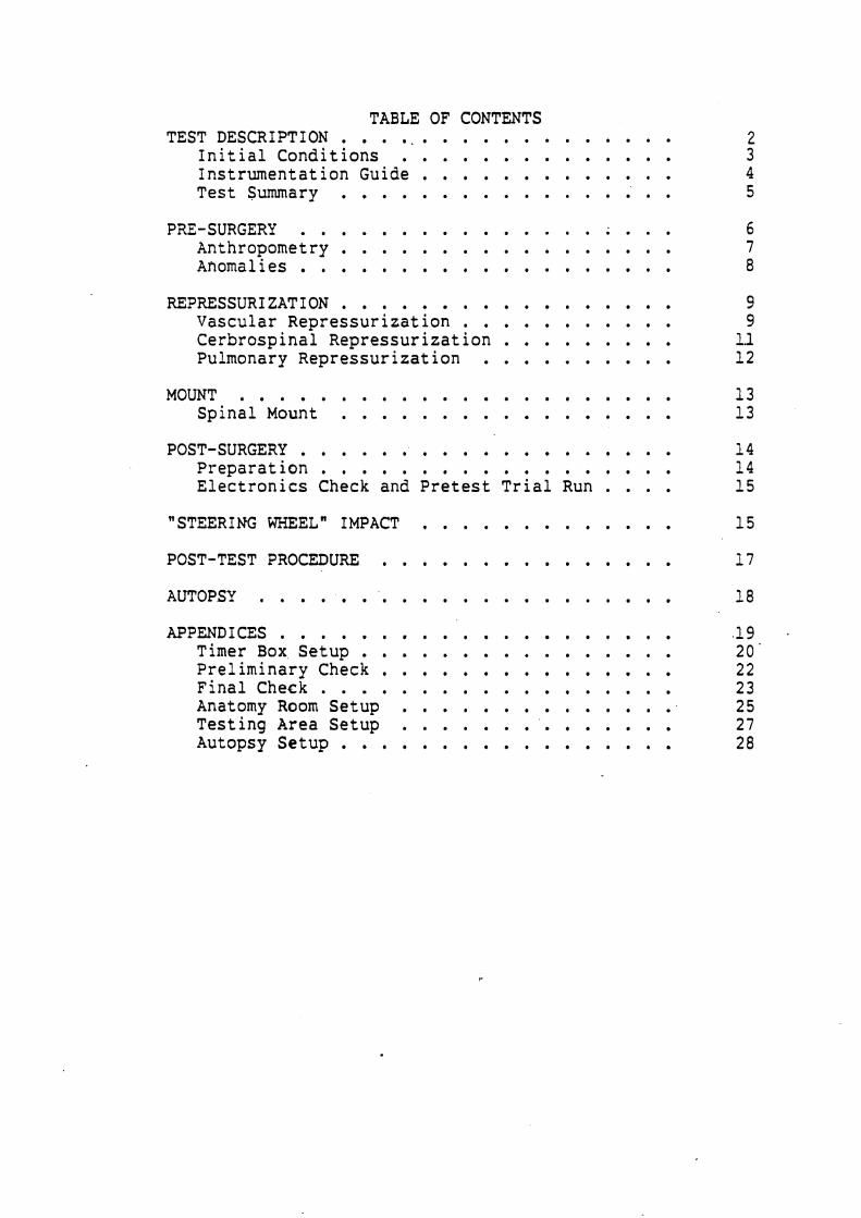
TABLE OF CONTENTS TESTDESCRIPTION . . . . . . . . . . . . . . . . . .
Initial Conditions . . . . . . . . . . . . . . Instrumentation Guide . . . . . . . . . . . . . Test Summary . . . . . . . . . . . . . . . . .
PRE-SURGERY . . . . . . . . . . . . . . . ; . . . Anthropometry . . . . . . . . . . . . . . . . . Anomalies . . . . . . . . . . . . . . . . . . .
REPRESSURIZATION . . . . . . . . . . . . . . . . . Vascular Repressurization . . . . . . . . . . . Cerbrospinal Repressurization . . . . . . . . . Pulmonary Repressurization . . . . . . . . . .
MOUNT . . . . . . . . . . . . . . . . . . . . . . SpinalMount . . . . . . . . . . . . . . . . .
POST-SURGERY . . . . . . . . . . . . . . . . Preparation . . . . . . . . . . . . . . . . . . Electronics Check and Pretest Trial Run . . . .
"STEERING WHEEL" IMPACT
. . . . . . . . . . . . . . . POST-TEST PROCEDURE
AUTOPSY . . . . . . . . . . . . . . . . . . . . . . APPENDICES . . . . . . . . . . . . . . . . . . . .
Timer Box . Setup . . . . . . . . . . . . . . . . Preliminary Check . . . . . . . . . . . . . . Finalcheck . . . . . . . . . . . . . . . . . . Anatomy Room Setup . . . . . . . . . . . . . . . . . . . . . Testing Area Setup . . . . . . . '
Autopsy Setup . . . . . . . . . . . . . . . . .

MVMA TEST SERIES OUTLINE
13 HUMAN CADAVER TESTS
Series A: 1 unrepressurized subject (20 kg and low velocity target=abdomen)
Series B: 1 repressurized-lung subject (20 kg and low velocity target=rib 10)
Series C: 1 unrepressurized subject (20 kg and low velocity target=substernale)
Series D: 1 repressurized pulmonary subject (20 kg and low velocity targetzsubsternale)
Series E: 1 unpressurized subject (20 kg and low velocity target=abdomen)
Series F: 1 repressurized pulmonary subject (20 kg high velocity target=abdomen)
TEST NO.
"STEERING WHEEL" IMPACT WITH PNEUMATIC BALLISTIC PENDULUM Contact surface: "Steerinq Wheeln shape psi: - low velocity=2.5 m/s or hioh= 10 m/s
15/25/50 kg striker
Camera Hycam Frame rate , lateral view
Cadaver Instrumentation T12 3ax Displacement stringpot at T12 Vascular Pressure - Millar transducer Pulmonary Pressure - Endevco transducer Post-test body core temperature
Equipment Instrumentation Force Velocity displacement 3ax on "Steering Wheeln column
Subject Posit ion I.
Supported via head and parachute harnesses, seated on table
*Test Descriptions
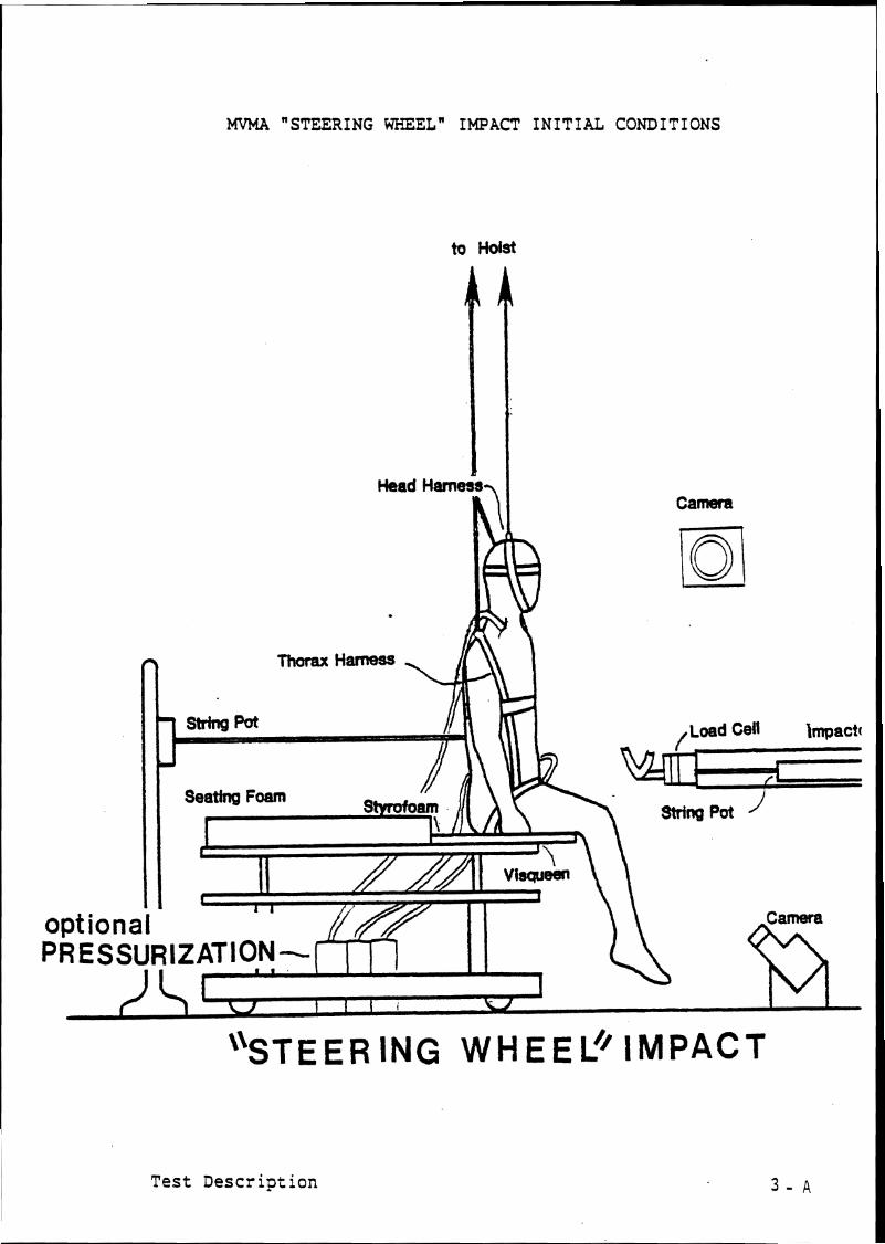
MVMA "STEERING WHEELw IMPACT INITIAL CONDITIONS
to Hoist
Head Hamegal I Camera
Test Description


March 13, 1986 86-87 M Series
HUMAN CADAVER TEST SUMMARY
Cadaver No, Sex: Height: Weight:
Test No, '
Test description:9 velocitv "Steerina Wheeln im~act 2 Thoraco-abdomen/Hiqh velocity "Steerins Wheel" impact to Thoraco-abdomen. Frontal impact to subject suspended seated on table. Restrictinq net for high velocity impact. -
Type of 1mpactor:~neumatic Ballistic Pendulum/
Striking Surface:"Steerins Wheelw model/
Pressure : Velocity m/s
35mrn stills:
- Black and White - Color CAMERAS
Hycam
FRAME RATE POSITION
Hycam
Notes:
Test Summary

CADAVER PRE-SURGERY
Pre-Surgery
COMMENTS TASK
Cadaver delivered from U of M Anatomy Dept, and transported to UMTRI Biomedical lab.
Weigh cadaver and log cadaver information.
Store cadaver if necessary.
Sanitary preparation.
Pretest X-rays: (KV/MA/T) (90/10/1)
thorax A-P / /
Start film hyping.
Anthropometry.
TIME

ANTHROPOMETRY
Cadaver Number : Sex: Age
Appearance:
Stature: Weight:
Head Circumference:
Head Length:
Head Breadth:
Menton-Vertex:
Menton-Suprasternale:
Neck Circumference
Acromion Height:
Suprasternale Height:
Substernale Height:
Substernale Circumference:
Axillary Breadth:
Chest Breadth:
Anthropometry

March 13, 1986 86-87 M Series
Anatomical Anomalies L.Clinical Observations
1. Neck:
2 . Thorax:
4. Other:
Anoma 1 i es

VASCULAR REPRESSURIZATION
Vascular Repressurization
TASK
Locate right carotid and cut lengthwise.
Locate right vertebral artery and ligate.
Loop six pieces of string around carotid artery.
Insert fabricated Foley catheter (#I81 into descending aorta past diaphragm.
Insert shield into ascending aorta.
Insert shield into carotid artery.
Insert arterial pressurization catheters into carotid artery.
Using syringe, squirt arcrylic into artery. Tie and sew.
Locate Le.ft carotid, cut, loop strings.
Locate left vertebral artery and ligate.
T IME COMMENTS

VASCULAR 'REPRESSURI ZATION cont inued
Vascular Repressurization
COMMENTS TASK
Insert arterial pressurization catheter ( # l o ) into carotid artery.
Acrylic, tie and sew.
Vascular flow check.
Locate right and left femoral arteries and insert into one a fabricated Foley catheter and tie the other off.
Seal the artery with the catheter in it.
TIME

CEREBROSPINAL REPRESSURIZATION
Cerebrospinal Repressu'rization
TASK
Locate L2 by palpation and counting from T12.
Core a small hole in the lamina with a drill bit.
Insert Foley catheter (#I41 such that balloon is in mid- thorax.
Insert small screws in lamina and process.
Seal off hole with acrylic,
Check for structural integrity of vertebra.
Check cerebrospinal flow.
TIME COMMENTS

PULMONARY REPRESSURIZATION
Pulmonary Repressurization
TASK
Locate trachea and cut lengthwise.
Loop two tie wraps around trachea,
Insert polyethelyne tube snugly, tie and sew.
Calibrate lungs.
Pulmonary pressure relief, valve calibration.
TIME
-
COMMENTS

SPINAL MOUNT
Mounts
TASK
Spinal mount goes on T12.
Make incisions over T12. Clear muscle and tissue away from process, but do not cut between processes.
Drill a small hole 1/4" deep in the process.
.Press flanking mount supports to spinous process.
Screw mount on with wood screw (be sure screw is in process).
Mold acrylic around and under mount and mount support and allow to dry. Make sure that the accelerometer mounting surface is free of acrylic.
Make sure accelerom- eter will be anatomically oriented.
Spinal geometry if necessary.
TIME COMMENTS

POST-SURGERY PREPARATION
Post-Surgery
TASK
Dress cadaver. (head and body harnesses)
S to re cadaver i f necessary.
Transport cadaver t o t e s t a r ea , being care- f u l not t o damage mount.
TIME COMMENTS

ELECTRONICS CHECK AND PRETEST TRIAL RUN
- Inspect triaxes for signs of wear - Complete wirinq - Establish and record gains settings - Calibrate tape recorder - Check pendulum load cell, velocity transducer, - Set timerbox - Check excitation and balances - Gate signal amplifier on . . - Suspend rubber- tube 5 inches from ballistic impactor
with fiber tape - Tape all accele?ometers to tube with paper tape - RUN TRIAL TEST
- Examine signals, check wiring if necessary - Verify operation of cameras and ropecutter - Test Endevco/Millar pressure transducers separately - Load Film
Hycam Hycam
Pretest Trial Run

"STEERING WHEEL" IMPACT
Test No,86M
psi: Velocity:2,5/ m/s
Thoraco-abdominal Impact
t
TASK
Attach phototargets.
Attach T12 triax to subject. Attach T12 stringpot to subject. Sew up incisions.
Attach Millar and Endevco pressure transducers to subject.
Final positioning of subject in impact field.
Measure and record head and neck angles Head:- Neck:-
Setup photos.
Hycam check
Final checklist.
Run test.
Take color 35mm final resting position photograph.
TIME COMMENTS

POST-TEST PROCEDURE
Post test
COMMENTS TASK
AFTER IN-PLACE POST-TEST PHOTOGRAPHS:
Remove all targets, pressure transducers and accelerometer.
Store cadaver i f necessary.
Transport cadaver to anatomy lab,
Remove spinal mount.
TIME

March 13, 1986 86-87 M Series
AUTOPSY
Observed Injuries
1. Neck:
TASK
Autopsy
2 . Thorax:
3 . Other:
TIME
COMMENTS :
COMMENTS
Autopsy

Appendices
APPENDICES Timer Box Setup
Preliminary and Final Checklists Preliminary Impact Lab
Cameras Sub j ec t
Cannon Final Checklist Final Countdown

"STEERING WHEEL" IMPACT TIMER BOX SETUP
TEST NUMBER86M psi = - velocity 2 . 5 / m/s
Control Equipment Delay Run
SET CANNON SOLENCID SWITCHES TO SYNCHRONIZE TIMING Cannon fire = Delay=
Timing

Checklists
PRELIMINARY AND FINAL CHECKLISTS

PRELIMINARY IMPACT LAB CHECKLIST
CAMERAS
Light banks positioned, 480-V power on? Cameras set and in position? Newtonian reference? Calibration Target positioned and photographed? Subject positioning completed? TEST ID and phototargets visible? Backdrop positioned? Cables clear of field of view?
- -
Pre-Test Photographs
SUBJECT PRELIMINARY CHECKLIST
- TARGETS visible? - Hoist in correct position and locked? Measure and record angles - GO TO CANNON FINAL CHECKLISTS
Pre-Check

FINAL CHECKLISTS
<CANNON FINAL CHECKLIST Solenoid Switches set to synchronize timer box? Timer Box times correct? Timer Box firing channels correct?
--
Cannon cocked? Piston status GREEN, GREEN, GRSEN? Record launch rope angle Head noose check All cables clear and strain relieved? Gate set? PRESSURIZE CANNON Ratchet and turn handle off brake winch? Force cal set in cannon room? Amps cal set in cannon room? Begin INSTRUMENTATION ROOM COUNTDOWN
<INSTRUMENTATION ROOM FINAL COUNTDOWN
Earphone contact? Necessary rewiring accomplished? Amplifier gains set? Amplifer excitation set? Amplifers zeroed? [balance] Tape recorders set at 30 ips? - volume of tape recorders
Tapes positioned? TEST N'JMBER VERIFIED? Cannon Timer Box Armed?
off?
RUN TEST
Final Check
March 13, 1986
Setup
86-87 M Series
SETUP CHECKLISTS
Anatomy Room Setup Testing Area Setup
Cart Setup Autopsy Setup
Timer Box Setup

March
MEASUREMENT
86-87 M Series
- Anthropometer - ~etric measuring tape
PAPER AND PLASTICS -- - Visqueen on autopsy table - Blue pads on table - Gauze
TAPES AND STRINGS -- - Silver tape - white tape - Flat waxed string
SCALPELS
- 2 medium ($4) handles - 2 small ( # 3 ) handles
- 5 #22 blades - 2 #15 blades - 2 #12 blades
FORCEPS
- 2 hooked - 2 large plain - 2 small plain
HEMOSTATS
- needle - small straight - large straight - large curved
Anatomy Room Setup

March 13, 1986 86-87 M Series
SCISSORS
- 2 medium SPREADERS
- 1 large - 1 medium
NEEDLES
- 2 double curved - 2 5cc sringes
CLOTHING
- Tampons - Thermoknit longjohns and top - Cotton socks - Blue vinyl pants and top - Head and body harnesses
BOLTS AND SCREWS -- - 3 lengths of wood screws
MOUNT
- Spine(1) - Dental acrylic
TOOLS
- Electric hair clippers - Electric drill w/key - Drill bits (NO. 7, approx, 1/16", etc.) - large screwdriver
Anatomy Room Setup

MISCELLANEOUS
- bone wax - TEST ID LABELS
TAPES
- fiber - silver - masking - black - double stick
PAPER AND PLASTIC -- - blue pads - gauze - gloves - plastic garbage bags
STRING
- flat waxed string TOOLS
- 2 small (2-56) screwdrivers - large screwdriver - 2-56 screws
Testing Area and Cart Setup

m aJ
2 r-f A
0 U3 #
N
I
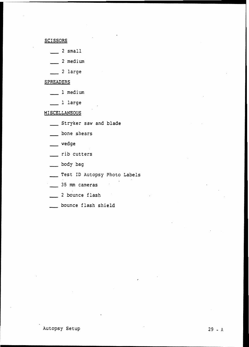
SCISSORS
- 2 small - 2 medium - 2 large
SPREADERS
- 1 medium - 1 large
MISCELLANEOUS
- Stryker saw and blade - bone shears - wedge - r i b cutters
- body bag - Test ID Autopsy Photo Labels
- 35 mm cameras - 2 bounce flash - bounce flash shield
Autopsy Setup

APPENDIX B - Selected Time-Histories

Run ID: 86M00l.B Fi t t e r : 100*4C Smooth:
1 FORCE
I G'S
Impact t o Abdomen

Run ID: 86M001C F i l t e r : 100*4C Smooth:
1 FORCE
1 PENDULUM
I G'S
a
Impact t o Abdomen
ACCEL G

Run ID: 86M00113
FORCE
LB
l-l
PENDULUM
TRACHEA
PSI
ACCEL
Fitter: 10014C Smooth:
I G'S
Impact t o Abdomen

Run ID: 863
TRACHEA
PSI
FORCE
PENDULUM ACCEL
Filter: 100*4C Smooth:
I G'S
Impact a t 10th R i b - Lower R i b Cage

Run ID: 86M002B Filter: 100*4C Smooth:
4
PENDULUM
PSI v
CV
ACCEL
z r [ FORCE
LB
I G'S
'Impact a t 1 0 t h R i b - Lower Rib Cage

Run ID: 86M002C Fi l t er : 100t4C Smooth:
FORCE
*
PENDULUM
TRACHEA
PSI
ACCEL
A I:T 12
G'S
Impact at 1 0 t h R i b - Lower R i b Cage

Run ID: 86M003A
1 TRACHEA
I PSI
AB Filter: 10014C Smooth:
C\2
a ACCEL 2 G
Ir)
FORCE
LB
Impact to Lower Sternum - Unrepressurized
4 4
A 1:T 12
G'S

Run ID: 86M003B
( FORCE
Fitter: 700*4C Smooth:
1 G'S
Impact t o Lower Sternum - Unrepressurized

Run ID: 86M003C Fi t t er : 100*4C Smooth:
l-4
I G'S
FORCE
LB
Impact t o Lower Sternum - Unrep ressu r i zed

Run ID: 86M004A Fil ter: 100*4C Smooth:
*
I G'S
FORCE
a
40 80 120 rns
PENDULUM ACCEL
G
Impact to Lower Sternum - Repressurized

Run 10: 86M004B
FORCE
PENDULUM ACCEL
F i t t e r : 100*4C Smooth:
I G'S
Impact to Lower Sternum - Repressurized

Run ID: 86M004C AB Fi t t e r : 100*4C Smooth:
1 TRACHEA d
PSI
02
FORCE
LB
a
Impact to Lower Sternum - Repressurized
PENDULUM ACCEL G
d 4
A l:T 12
G'S

Run ID: 86M004D F i t t e r : 100*4C Smooth:
1 TRACHEA
I PSI
PENDULUM
02
ACCEL
FORCE
LB
I G'S
Impact to Lower Sternum - Repressurized

Run ID: 86M004E
4
1 PENDULUM
TRACHEA
PSI
CV
a ACCEL
FORCE
LB
Fil ter: 100*4C Smooth:
I G'S
I n ~ a c t t o Lower Sternum - Repressurized

Run ID: 86M005A F i t t e r : 100*4C S m o o t h :
4
COMP a CE
TRACHEA
PSI
FOR
I G'S
Impact t o Abdomen

Run ID: 86M005B Filter: 100*4C Smooth:
1 TRACHEA
+ l PSI
I G'S
02
Impact t o Abdomen
FORCE
bB

Run ID: 86M005C Fi l t e r : 100t4C Smooth:
d
A l:T 12 4 d
G'S
TRACHEA
PSI
N
Impact t o Abdomen
FORCE

Run ID: 86M006 Filter: 400*4C Smooth:
4
TRACHEA
PSI
PENDULUM
CV
ACCEL
FORCE
LB
I G'S
High Velocity Impact 10-m/s