UML – Design the software for an Auto Teller Machine (ATM)
25
Session – 2 Session Name: UML – Design the software for an Auto Teller Machine (ATM) Author Name: R.Suresh Department: Information Technology Subject/Course: UML Cell Number: +91 - 9655228850
-
Upload
suresh-ramanujam -
Category
Education
-
view
387 -
download
2
Transcript of UML – Design the software for an Auto Teller Machine (ATM)

Session – 2
Session Name: UML – Design the software for an Auto Teller Machine (ATM)
Author Name: R.Suresh Department: Information Technology
Subject/Course: UML Cell Number: +91 - 9655228850

Software Testing Principles & Techniques Page 2 Author Name: R.Suresh College Name: Sri Manakula Vinayagar Engineering College

Session Objectives At the end of this session, the learner will be able to: ● Define Test cases ● Define Report Writing ● Define UML ● Identify the Purpose of Release ● Summarize the Limitations of Jar File ● Breakdown the various advantages of Ear File ● Define Various types of UI Testing ● Setup the Acceptance Testing Environment ● Differentiate between Jar and War File ● Differentiate between War and Ear File ● Breakdown the Inputs for testers ● Define Integrated Testing ● Breakdown the various advantages of System Testing ● Define Acceptance Testing ● Differentiate between Application Server and Web Server ● Define Use Cases ● Identify the Various Use Cases for Unit Testing ● Breakdown the Outcomes for Testers ● Define JUnit ● Define More Info ● Summarize various testing tools available the Market ● Define VSS ● Define Standalone Application ● Define Path Testing
Teaching Learning Material ● Demonstration ● Slide Presentation ● Data Sheets ● UML Manuals
Software Testing Principles & Techniques Page 3 Author Name: R.Suresh College Name: Sri Manakula Vinayagar Engineering College

Session Plan
Time (in min)
Content Learning Aid
and Methodology
Faculty Approach
Typical Student Activity
Learning Outcomes (Blooms + Gardeners)
5 Recap: Introduction to USECASE Diagram Discussion Explains Listens
Comprehension Intrapersonal
5
Draw a use case diagram for the ATM
Prototype Models
Monitors Identifies
Knowledge Comprehension Application Analysis Synthesis Evaluation
5
Describe the use case
Discussion
Guides Discussion
Knowledge Comprehension Application Analysis Synthesis Evaluation
10
Draw a domain class diagram for the ATM
Prototype Models
Monitors Identifies
Comprehension Application Analysis Synthesis Evaluation
10
Draw a design‐level sequence diagram to implement the use case
Prototype Models
Monitors Identifies
Knowledge Comprehension
5
Draw the collaboration diagram corresponding the sequence diagram
Prototype Models
Monitors Identifies
Comprehension Intrapersonal
5
Draw the collaboration diagram corresponding the sequence diagram
Prototype Models
Monitors Identifies
Comprehension Application Analysis Synthesis Evaluation
Software Testing Principles & Techniques Page 4 Author Name: R.Suresh College Name: Sri Manakula Vinayagar Engineering College

5 Conclusion Recap Explains Listens Comprehension Intrapersonal
Session Inputs
UML USECASE Diagrams
The learners may have understand the Unified Modeling Language and orient towards Object Oriented methodology using UML for modeling software systems.
In particular, it is intended for software professionals who have sound knowledge of object concepts and some experience towards analysis and design. Prerequirments: Good understanding of object concepts. Sound knowledge of any object oriented language. Knowledge of software engineering process frequently heard about the terms Unified Markup Language and various use case diagrams involved in the UML.So, they would have some understanding & knowledge about the terms
Software Testing Principles & Techniques Page 5 Author Name: R.Suresh College Name: Sri Manakula Vinayagar Engineering College

Good understanding of various models like structural, Behavioral Models Task 1: Getting Started. i. Start up Visio from the start menu
Start -> programs -> Microsoft Office -> Microsoft Office Visio 2003 Or alternatively double click the Visio 2003 icon from the desktop. Note: It may take a while for Visio 2003 to start up so don’t panic. Also you might be getting some messages stating that some files could not be found. Please click Ok on the messages and ignore them. Youmight get two or three suchmessages before Visio starts up so don’t panic.
ii. The following screen would appear
DataFlow Diagram:-
Software Testing Principles & Techniques Page 6 Author Name: R.Suresh College Name: Sri Manakula Vinayagar Engineering College

● Click software from above and choose dataflow model diagram
(metric).
● You can see on the left hand side the “Gane-Sarson” model icons. Try dragging them on the worksheet and draw some sample DFD diagrams from your lectures.
UML Model Diagram Click Software from the category on the left and select UML Model Diagram(Metric) to open a blank Visio drawing
Task 2: Understanding Visio 2003 Interface
If you are successful so far you will be able to see Visio 2003 main interface Window now. Familiarize yourself with the main components of the Window.
Software Testing Principles & Techniques Page 7 Author Name: R.Suresh College Name: Sri Manakula Vinayagar Engineering College

The best way to understand and learn Visio environment is going through the getting started tutorial for Visio 2003. To access this tutorial go to Help menu and select Getting Started Tutorial. From the tutorial, go through the tutorial on The Microsoft Office Visio 2003 environment and Create Diagrams.
Software Testing Principles & Techniques Page 8 Author Name: R.Suresh College Name: Sri Manakula Vinayagar Engineering College

Task 3: Saving your work
To save your model, youwill need to save themodel as a Visio drawing. To save a drawing go to File> Save As… or you can click on the diskette symbol from the standard toolbar. In the save as dialog box, enter Lab1 for the filename. It is a good idea to create a separate folder to store all the lab exercises. Make sure that the file type is Drawing. This will save your file with a .vsd extension.
Software Testing Principles & Techniques Page 9 Author Name: R.Suresh College Name: Sri Manakula Vinayagar Engineering College

Task 4: Representing Generalization, Aggregation and Association.
1. Modeling Generalization:
i. In theModel Explorer, click the + sign beside the Static Model to reveal Top Package. When you create a new model, the UML Model Diagram template automatically creates a top package for the model. This package serves as the container for all the elements, packages, and diagrams you create as part of the model.
ii. Right Click the Top Package and from the menu select New > Static Structure Diagram. [see diagram on next page]
Software Testing Principles & Techniques Page 10 Author Name: R.Suresh College Name: Sri Manakula Vinayagar Engineering College

iii. This opens up a new blank static structure diagram in the drawing environment. And a new item appears under the Top Package in the Model Explorer with the name Static Structure -1. Right click the Static Structure – 1 in theModel Explorer and click rename. Change its name to Describing Generalization.
Software Testing Principles & Techniques Page 11 Author Name: R.Suresh College Name: Sri Manakula Vinayagar Engineering College

iv. Now click the UML Static Structure (Metric) in the shapes explorer to reveal the shapes available in drawing a static structure diagram.
v. Select the Class shape from the stencil and drag it to the drawing environment. Double click the class to open its properties page. Change its name to Bank Card Class.
Software Testing Principles & Techniques Page 12 Author Name: R.Suresh College Name: Sri Manakula Vinayagar Engineering College

vi. Select the Class shape again from the stencil and drag it to the drawing environment releasing the mouse somewhere below the Bank Card Class. Double click the class to open its properties page. Change its name to Credit Card Class.
vii. Now select scroll through the shapes and select Generalization from the stencil and drag it to the drawing
environment and release your mouse away from both the classes.
viii. Select the line that gets drawn and drag the end with the triangle tip onto the edge of the Bank Card Class; onto one of the purple “x” marks on the edge of the class. As soon as the end of the line changes from green to red release the mouse. The red indicator means that the line is “glued” to
Software Testing Principles & Techniques Page 13 Author Name: R.Suresh College Name: Sri Manakula Vinayagar Engineering College

some object. Similarly drag the other end and “glue” it to the Credit Card Class.
ix. You have now represented a generalization relationship x. You can save the work you have done so far.
2. Adding Attributes and Operations
i. Now we will try to add an attribute and a operation to the Bank Card Class
ii. Double click the Bank Card Class to open its properties page and click on the Attributes category.
iii. Double click on the Attribute field and type cardNumber. Choose the type as VB::String (or any type you prefer). Leave Visibility as it is because we want this attribute to be private to this class. Accept the rest of default values.
Software Testing Principles & Techniques Page 14 Author Name: R.Suresh College Name: Sri Manakula Vinayagar Engineering College
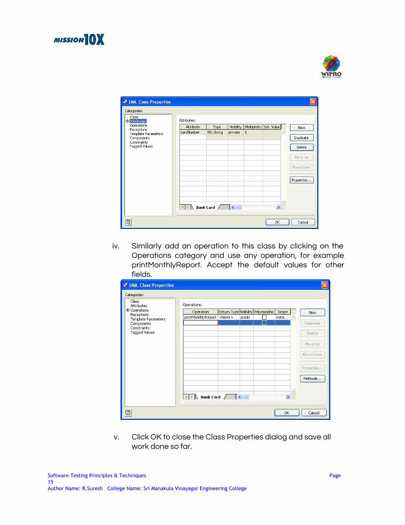
iv. Similarly add an operation to this class by clicking on the Operations category and use any operation, for example printMonthlyReport. Accept the default values for other fields.
v. Click OK to close the Class Properties dialog and save all work done so far.
Software Testing Principles & Techniques Page 15 Author Name: R.Suresh College Name: Sri Manakula Vinayagar Engineering College

3.
Modeling Aggregation:
i. Make a new static structure diagram: Right Click the Top Package and from the menu: New > Static StructureDiagram. Rename this diagram to Describing Aggregation
ii. You can switch between the static structures or UML diagrams by simply doubly clicking on the name of the static structure in the Model Explorer.
iii. In the blank diagram follow the steps used while representing generalization. But this time for the first class use the name “Car Class”, and “Chassis Class” as the name of the second class. But this time the relationship between the two should Aggregation. Select Composition shape from the stencils. A line gets created with one end labeled End1 and the other End2. End 1 contains a blank diamond at the end. Click on End1 and drag it to end of Car Class. As soon as the end of the line
Software Testing Principles & Techniques Page 16 Author Name: R.Suresh College Name: Sri Manakula Vinayagar Engineering College

changes from green to red release themouse. The red indicator means that the line is “glued” to some object. Similarly drag End2 and “glue” it to the Chassis Class. Currently End1 is represented by a solid black diamond. This indicates a stronger form of aggregation. You can ignore this for the time being.
iv. To change the relationship into a normal aggregation relationship, double click the line joining the two classes to open its properties page. Select End1 from the Association Ends table and click Properties. Change the Aggregation type to shared. [See diagram below]. Click Ok twice to close both the properties pages. You can also change the name of the Association and the name of the Associations Ends using the UML Association dialog. You can also change the multiplicity. Try changing the values of these fields. You need to double click on fields that have text, for example, name of Association End. If you do not want names for Association End or Multiplicity then simply delete values in the fields.
v. You have now represented an aggregation relationship where a car class consists of a chassis class. Figure out how to change the multiplicity.
Software Testing Principles & Techniques Page 17 Author Name: R.Suresh College Name: Sri Manakula Vinayagar Engineering College

Challenge
● If you have extra time, try to extend the aggregation relationship so that the car class consists of the Chassis class, Engine class and the Wheels class.
● Create a new class diagram and draw the Association relationship shown below.
Software Testing Principles & Techniques Page 18 Author Name: R.Suresh College Name: Sri Manakula Vinayagar Engineering College

Use Cases for Example ATM System
Suggested Activity: ATM ( Group and Team Work )
Software Testing Principles & Techniques Page 19 Author Name: R.Suresh College Name: Sri Manakula Vinayagar Engineering College

Design the software for an automated teller machine (ATM). The ATMs are capable of only withdrawal of cash for this example. An ATMAccepts a cash card, interacts with the user, verifies the PIN number provided, carries out the transaction, dispenses cash, and prints receipts.ATMs communicate with a central computer, which clears the transactions with the appropriate bank.
Suggested Activity: ATM ( Experiments and Practicals)
Draw a use case diagram for the ATM Describe the use case Draw a domain class diagram for the ATM Draw a design-level sequence diagram to implement the use case Draw the collaboration diagram corresponding the sequence diagram Draw a design-level class diagram of the ATM software Draw state diagrams for active objects in your design
Please check Visio 2003 started successfully. Learners should Know the components of Visio 2003 interface. Recognize and understand some of the icons in the browser and toolbox. Be able to save the diagrams and models you have created Be able to model to generalization, aggregation and association Explain what a use case model is. Draw a Use Case diagram using Visio 2003. Draw sequence diagrams using Visio. Draw collaboration diagrams using Visio. Draw state chart diagrams using Visio.
UML – Design the Software for an Automated Teller Machine(ATM)
Software Testing Principles & Techniques Page 20 Author Name: R.Suresh College Name: Sri Manakula Vinayagar Engineering College
Software Testing Principles & Techniques Page 21 Author Name: R.Suresh College Name: Sri Manakula Vinayagar Engineering College

Summary In this session, we learnt to:
● Define Jar File
o Execute the Standalone Applications ● Define War File
o Execute the Web Based Applications ● Define Ear File
o Execute the Distributed Web Based Applications ● Identify the Purpose of Release
o Patch set of modules are called ad Release ● Summarize the Limitations of Jar File
o Execute the Product in the Standalone Machines ● Breakdown the various advantages of Ear File
o Deploy the Ear file into Various Distributed Environment ● Summarize Various Job Openings for Testers
o Testing Manager(QAM) o Test Lead o Testers
● Setup the Acceptance Testing Environment o Client needs executable file to simulate the product their Environment
● Differentiate between Jar and War File o Executing the Product in the Standalone Application o Executing the Product in the Web Applications
● Differentiate between War and Ear File o Executing the Product in the Web Applications o Executing the product in the Distributed Environment
● Breakdown the Inputs for testers o Test Cases o SRS o Jar File o Product
● Define Integrated Testing o Code o Build File
Software Testing Principles & Techniques Page 22 Author Name: R.Suresh College Name: Sri Manakula Vinayagar Engineering College
● Breakdown the various advantages of System Testing
o Different Platform o Jar File o Product
● Define Acceptance Testing o Client side Validation
● Differentiate between Application Server and Web Server o Application Server is used for Distributed Applications o Web Server is used for web Applications
● Define Use Cases o Simulate the Product in the Graphical Format
● Identify the Various Use Cases for Unit Testing o Code Quality o Coding Standards
● Breakdown the Outcomes for Testers o Ensure the Valid Product or Not o Quality of the Product
● Define JUnit o Check the Products based on the test cases in the Development
Environment ● Define More Info
o Steps are not defined in the Automated tool properly thenmake it asmore info
● Summarize various testing tools available the Market o Bugzilla o TestTrackPro
● Define VSS o Visual Source Safe it maintains history of the Development Code
● Define Standalone Application
o User wants to run the Product in the single Dedicated machine ● Define Path Testing
o Percentage of task completed in the Requirement Coverage
Software Testing Principles & Techniques Page 23 Author Name: R.Suresh College Name: Sri Manakula Vinayagar Engineering College

Assignment
(1) Develop a design for your group’s part of the robot system.
Pay particular attention to the correct and appropriate use of object-oriented design, concurrent design, and the associated design notations.
Your software will have to interact with the software developed by your cooperating group. The point of interaction is the communications protocol. Make sure that design decisions associated with the communications protocol are carefully hidden.
(2) Document the design carefully including:
● A comprehensive document structure (face page, approval, contents, etc.).
● A high-level system architecture overview/summary in natural language, using graphics wherever it makes sense.
● Static structure using the UML class diagram and package notations.
● Object interaction structure using the UML sequence diagrams.
● The concurrent structure of your design using any informal notation that you choose.
● Class interfaces in C#with comments that document the design decision that each class is hiding. For each member function, include a comment explaining the purpose of the function and what each parameter is for. The interfaces should reflect accurately the class diagrams you have drawn except that class diagrams need not include constructors, destructors, and getter and setter methods for private data members.
● Other natural language text as necessary (but no novels).
Software Testing Principles & Techniques Page 24 Author Name: R.Suresh College Name: Sri Manakula Vinayagar Engineering College

References
● Ian Somerville, "Software Engineering", Sixth Edition, Pearson Education,
2001. ● MACIASZEK, L.A. and LIONG, B.L. (2005):Practical Software Engineering. A
Case Study Approach Addison Wesley, Harlow England, 864p
Software Testing Principles & Techniques Page 25 Author Name: R.Suresh College Name: Sri Manakula Vinayagar Engineering College