UM1713 User manual - st.com · 6.1.3 UDP echo client ... 6.1.5 UDP TCP echo server based on netconn...
41
May 2015 DocID025731 Rev 4 1/41 1 UM1713 User manual Developing applications on STM32Cube with LwIP TCP/IP stack Introduction STMCube™ is an STMicroelectronics original initiative to ease developers life by reducing development efforts, time and cost. STM32Cube covers STM32 portfolio. STM32Cube Version 1.x includes: • The STM32CubeMX, a graphical software configuration tool that allows to generate C initialization code using graphical wizards. • A comprehensive embedded software platform, delivered per series (such as STM32CubeF4 for STM32F4 series) – The STM32Cube HAL, an STM32 abstraction layer embedded software, ensuring maximized portability across STM32 portfolio – A consistent set of middleware components such as RTOS, USB, TCP/IP, Graphics – All embedded software utilities coming with a full set of examples. Some STM32 microcontrollers feature a high-quality 10/100 Mbit/s Ethernet peripheral that supports both Media Independent Interface (MII) and Reduced Media Independent Interface (RMII) to interface with the Physical Layer (PHY). When working with an Ethernet communication interface, a TCP/IP stack is mostly used to communicate over a local or a wide area network. This user manual is intended for developers who use STM32Cube firmware on STM32 microcontrollers. It provides a full description of how to integrate a free middleware TCP/IP stack using STM32Cube HAL drivers into an embedded application based on STM32 microcontroller. The middleware TCP/IP stack is the LwIP (Lightweight IP) which is an open source stack intended for embedded devices. A dedicated STM32Cube firmware package is provided for each series. It includes Ethernet HAL driver, LwIP middleware and application examples with and without RTOS running on ST evaluation boards. Note: This document is applicable to all STM32 series featuring an Ethernet peripheral. However, or simplicity reason, STM32F4xx and STM32CubeF4 are used as reference platform. The same description, file names and screenshot are applicable as well to other series offering Ethernet connectivity, such as STM32F107xx, STM32F2x7xx and STM32F7xx. To know more about the Ethernet examples implementation on your STM32 series, refer to the documentation provided within the associated STM32Cube firmware package. www.st.com
Transcript of UM1713 User manual - st.com · 6.1.3 UDP echo client ... 6.1.5 UDP TCP echo server based on netconn...
May 2015 DocID025731 Rev 4 1/41
1
UM1713User manual
Developing applications on STM32Cube with LwIP TCP/IP stack
Introduction
STMCube™ is an STMicroelectronics original initiative to ease developers life by reducing development efforts, time and cost. STM32Cube covers STM32 portfolio.
STM32Cube Version 1.x includes:
• The STM32CubeMX, a graphical software configuration tool that allows to generate C initialization code using graphical wizards.
• A comprehensive embedded software platform, delivered per series (such as STM32CubeF4 for STM32F4 series)
– The STM32Cube HAL, an STM32 abstraction layer embedded software, ensuring maximized portability across STM32 portfolio
– A consistent set of middleware components such as RTOS, USB, TCP/IP, Graphics
– All embedded software utilities coming with a full set of examples.
Some STM32 microcontrollers feature a high-quality 10/100 Mbit/s Ethernet peripheral that supports both Media Independent Interface (MII) and Reduced Media Independent Interface (RMII) to interface with the Physical Layer (PHY).
When working with an Ethernet communication interface, a TCP/IP stack is mostly used to communicate over a local or a wide area network.
This user manual is intended for developers who use STM32Cube firmware on STM32 microcontrollers. It provides a full description of how to integrate a free middleware TCP/IP stack using STM32Cube HAL drivers into an embedded application based on STM32 microcontroller.
The middleware TCP/IP stack is the LwIP (Lightweight IP) which is an open source stack intended for embedded devices.
A dedicated STM32Cube firmware package is provided for each series. It includes Ethernet HAL driver, LwIP middleware and application examples with and without RTOS running on ST evaluation boards.
Note: This document is applicable to all STM32 series featuring an Ethernet peripheral. However, or simplicity reason, STM32F4xx and STM32CubeF4 are used as reference platform. The same description, file names and screenshot are applicable as well to other series offering Ethernet connectivity, such as STM32F107xx, STM32F2x7xx and STM32F7xx. To know more about the Ethernet examples implementation on your STM32 series, refer to the documentation provided within the associated STM32Cube firmware package.
www.st.com

Contents UM1713
2/41 DocID025731 Rev 4
Contents
1 LwIP TCP/IP stack description . . . . . . . . . . . . . . . . . . . . . . . . . . . . . . . . . 6
1.1 Stack features . . . . . . . . . . . . . . . . . . . . . . . . . . . . . . . . . . . . . . . . . . . . . . . 6
1.2 License . . . . . . . . . . . . . . . . . . . . . . . . . . . . . . . . . . . . . . . . . . . . . . . . . . . . 6
1.3 LwIP architecture . . . . . . . . . . . . . . . . . . . . . . . . . . . . . . . . . . . . . . . . . . . . 7
1.4 LwIP stack folder organization of the . . . . . . . . . . . . . . . . . . . . . . . . . . . . 8
1.5 LwIP API overview . . . . . . . . . . . . . . . . . . . . . . . . . . . . . . . . . . . . . . . . . . . 9
1.5.1 Raw API . . . . . . . . . . . . . . . . . . . . . . . . . . . . . . . . . . . . . . . . . . . . . . . . . . 9
1.5.2 Netconn API . . . . . . . . . . . . . . . . . . . . . . . . . . . . . . . . . . . . . . . . . . . . . . 10
1.5.3 Socket API . . . . . . . . . . . . . . . . . . . . . . . . . . . . . . . . . . . . . . . . . . . . . . . 11
1.6 LwIP buffer management . . . . . . . . . . . . . . . . . . . . . . . . . . . . . . . . . . . . . .11
1.6.1 Packet buffer structure . . . . . . . . . . . . . . . . . . . . . . . . . . . . . . . . . . . . . . 11
1.6.2 pbuf management APIs . . . . . . . . . . . . . . . . . . . . . . . . . . . . . . . . . . . . . 12
2 Interfacing LwIP with STM32Cube Ethernet HAL driver . . . . . . . . . . . 14
3 LwIP configuration . . . . . . . . . . . . . . . . . . . . . . . . . . . . . . . . . . . . . . . . . 16
3.1 Modules support . . . . . . . . . . . . . . . . . . . . . . . . . . . . . . . . . . . . . . . . . . . . 16
3.2 Memory configuration . . . . . . . . . . . . . . . . . . . . . . . . . . . . . . . . . . . . . . . . 16
4 Developing applications with LwIP stack . . . . . . . . . . . . . . . . . . . . . . . 18
4.1 Developing in standalone mode using the Raw API . . . . . . . . . . . . . . . . 18
4.1.1 Operation model . . . . . . . . . . . . . . . . . . . . . . . . . . . . . . . . . . . . . . . . . . 18
4.1.2 Example of TCP echo server demonstration . . . . . . . . . . . . . . . . . . . . . 19
4.2 Developing with an RTOS using Netconn or Socket API . . . . . . . . . . . . . 22
4.2.1 Operation model . . . . . . . . . . . . . . . . . . . . . . . . . . . . . . . . . . . . . . . . . . 22
4.2.2 Example of a TCP echoserver demonstration using the Netconn API . 23
5 LwIP package description . . . . . . . . . . . . . . . . . . . . . . . . . . . . . . . . . . . 26
5.1 LwIP package directories . . . . . . . . . . . . . . . . . . . . . . . . . . . . . . . . . . . . . 26
5.2 Applications settings . . . . . . . . . . . . . . . . . . . . . . . . . . . . . . . . . . . . . . . . . 26
5.2.1 PHY interface configuration . . . . . . . . . . . . . . . . . . . . . . . . . . . . . . . . . . 26
5.2.2 MAC and IP address settings . . . . . . . . . . . . . . . . . . . . . . . . . . . . . . . . 27
5.2.3 Firmware features . . . . . . . . . . . . . . . . . . . . . . . . . . . . . . . . . . . . . . . . . 27
DocID025731 Rev 4 3/41
UM1713 Contents
3
5.3 Evaluation boards settings . . . . . . . . . . . . . . . . . . . . . . . . . . . . . . . . . . . . 27
6 Using the LwIP applications . . . . . . . . . . . . . . . . . . . . . . . . . . . . . . . . . . 28
6.1 Getting started applications . . . . . . . . . . . . . . . . . . . . . . . . . . . . . . . . . . . 28
6.1.1 TCP echo client . . . . . . . . . . . . . . . . . . . . . . . . . . . . . . . . . . . . . . . . . . . 28
6.1.2 TCP Echo server . . . . . . . . . . . . . . . . . . . . . . . . . . . . . . . . . . . . . . . . . . 29
6.1.3 UDP echo client . . . . . . . . . . . . . . . . . . . . . . . . . . . . . . . . . . . . . . . . . . . 30
6.1.4 UDP echo server . . . . . . . . . . . . . . . . . . . . . . . . . . . . . . . . . . . . . . . . . . 31
6.1.5 UDP TCP echo server based on netconn AP . . . . . . . . . . . . . . . . . . . . 32
6.2 Features applications . . . . . . . . . . . . . . . . . . . . . . . . . . . . . . . . . . . . . . . . 33
6.2.1 Web server based on raw API . . . . . . . . . . . . . . . . . . . . . . . . . . . . . . . . 33
6.2.2 Web server based on netconn API . . . . . . . . . . . . . . . . . . . . . . . . . . . . 35
6.2.3 Web server based on socket API . . . . . . . . . . . . . . . . . . . . . . . . . . . . . 36
6.3 Integrated applications . . . . . . . . . . . . . . . . . . . . . . . . . . . . . . . . . . . . . . . 37
6.3.1 TFTP server . . . . . . . . . . . . . . . . . . . . . . . . . . . . . . . . . . . . . . . . . . . . . . 37
7 Conclusion . . . . . . . . . . . . . . . . . . . . . . . . . . . . . . . . . . . . . . . . . . . . . . . . 38
Appendix A FAQ . . . . . . . . . . . . . . . . . . . . . . . . . . . . . . . . . . . . . . . . . . . . . . . . . . . 39
A.1 How do I choose between static or dynamic (DHCP) IP address allocation?. . . . . . . . . . . . . . . . . . . . . . . . . . . . . . . . . . . . . . . . 39
A.2 How does the application behave when the Ethernet cable is disconnected? . . . . . . . . . . . . . . . . . . . . . . . . . . . . . . . . . . . . . . . . . . . . 39
A.3 How can the application be ported on a different hardware? . . . . . . . . . . 39
8 Revision history . . . . . . . . . . . . . . . . . . . . . . . . . . . . . . . . . . . . . . . . . . . 40

List of tables UM1713
4/41 DocID025731 Rev 4
List of tables
Table 1. TCP Raw API functions . . . . . . . . . . . . . . . . . . . . . . . . . . . . . . . . . . . . . . . . . . . . . . . . . . . . 9Table 2. UDP Raw API functions . . . . . . . . . . . . . . . . . . . . . . . . . . . . . . . . . . . . . . . . . . . . . . . . . . . 10Table 3. Netconn API functions . . . . . . . . . . . . . . . . . . . . . . . . . . . . . . . . . . . . . . . . . . . . . . . . . . . . 10Table 4. Socket API functions. . . . . . . . . . . . . . . . . . . . . . . . . . . . . . . . . . . . . . . . . . . . . . . . . . . . . . 11Table 5. Pbuf API functions . . . . . . . . . . . . . . . . . . . . . . . . . . . . . . . . . . . . . . . . . . . . . . . . . . . . . . . 13Table 6. Ethernet interface functions description . . . . . . . . . . . . . . . . . . . . . . . . . . . . . . . . . . . . . . . 14Table 7. LwIP memory configuration . . . . . . . . . . . . . . . . . . . . . . . . . . . . . . . . . . . . . . . . . . . . . . . . 16Table 8. LwIP applications categories . . . . . . . . . . . . . . . . . . . . . . . . . . . . . . . . . . . . . . . . . . . . . . . 28Table 9. Document revision history . . . . . . . . . . . . . . . . . . . . . . . . . . . . . . . . . . . . . . . . . . . . . . . . . 40
DocID025731 Rev 4 5/41
UM1713 List of figures
5
List of figures
Figure 1. LwIP architecture . . . . . . . . . . . . . . . . . . . . . . . . . . . . . . . . . . . . . . . . . . . . . . . . . . . . . . . . . 8Figure 2. Figure 2 LwIP folder organization . . . . . . . . . . . . . . . . . . . . . . . . . . . . . . . . . . . . . . . . . . . . . 8Figure 3. Pbuf structure . . . . . . . . . . . . . . . . . . . . . . . . . . . . . . . . . . . . . . . . . . . . . . . . . . . . . . . . . . . 12Figure 4. Standalone operation model . . . . . . . . . . . . . . . . . . . . . . . . . . . . . . . . . . . . . . . . . . . . . . . . 18Figure 5. LwIP operation model with RTOS. . . . . . . . . . . . . . . . . . . . . . . . . . . . . . . . . . . . . . . . . . . . 22Figure 6. TCP echo client . . . . . . . . . . . . . . . . . . . . . . . . . . . . . . . . . . . . . . . . . . . . . . . . . . . . . . . . . 29Figure 7. TCP echo server . . . . . . . . . . . . . . . . . . . . . . . . . . . . . . . . . . . . . . . . . . . . . . . . . . . . . . . . . 30Figure 8. UDP echo client . . . . . . . . . . . . . . . . . . . . . . . . . . . . . . . . . . . . . . . . . . . . . . . . . . . . . . . . . 31Figure 9. UDP echo server . . . . . . . . . . . . . . . . . . . . . . . . . . . . . . . . . . . . . . . . . . . . . . . . . . . . . . . . 32Figure 10. Web server home page . . . . . . . . . . . . . . . . . . . . . . . . . . . . . . . . . . . . . . . . . . . . . . . . . . . 34Figure 11. SSI use in HTTP server . . . . . . . . . . . . . . . . . . . . . . . . . . . . . . . . . . . . . . . . . . . . . . . . . . . 35Figure 12. Web server list of task page . . . . . . . . . . . . . . . . . . . . . . . . . . . . . . . . . . . . . . . . . . . . . . . . 36Figure 13. TFTP tool (tftpd32) . . . . . . . . . . . . . . . . . . . . . . . . . . . . . . . . . . . . . . . . . . . . . . . . . . . . . . . 37
LwIP TCP/IP stack description UM1713
6/41 DocID025731 Rev 4
1 LwIP TCP/IP stack description
1.1 Stack features
LwIP is a free TCP/IP stack developed by Adam Dunkels at the Swedish Institute of Computer Science (SICS) and licensed under a modified BSD license.
The focus of the LwIP TCP/IP implementation is to reduce RAM usage while keeping a full scale TCP/IP stack. This makes LwIP suitable for use in embedded systems.
LwIP comes with the following protocols:
• IPv4 and IPv6 (Internet Protocol v4 and v6)
• ICMP (Internet Control Message Protocol) for network maintenance and debugging
• IGMP (Internet Group Management Protocol) for multicast traffic management
• UDP (User Datagram Protocol)
• TCP (Transmission Control Protocol)
• DNS (Domain Name Server)
• SNMP (Simple Network Management Protocol)
• DHCP (Dynamic Host Configuration Protocol)
• PPP (Point to Point Protocol)
• ARP (Address Resolution Protocol)
LwIP has three application programming interfaces (APIs):
• Raw API is the native LwIP API. It enables the development of applications using event callbacks. This API provides the best performance and optimized code size, but adds some complexity to application development.
• Netconn API is a high-level sequential API that requires a real-time operating system (RTOS). The Netconn API enables multithreaded operations.
• BSD Socket API: Berkeley-like Socket API (developed on top of the Netconn API)
The source code for the LwIP stack can be downloaded from http://savannah.nongnu.org.
1.2 License
LwIP is licensed under the BSD license. Below is a copy of the LwIP license document that is included in the source codes:
/*
* Copyright (c) 2001-2004 Swedish Institute of Computer Science.
* All rights reserved.
*
* Redistribution and use in source and binary forms, with or without modification,
* are permitted provided that the following conditions are met:
*
* 1. Redistributions of source code must retain the above copyright notice,
* this list of conditions and the following disclaimer.

DocID025731 Rev 4 7/41
UM1713 LwIP TCP/IP stack description
40
* 2. Redistributions in binary form must reproduce the above copyright notice,
* this list of conditions and the following disclaimer in the documentation
* and/or other materials provided with the distribution.
* 3. The name of the author may not be used to endorse or promote products
* derived from this software without specific prior written permission.
*
* THIS SOFTWARE IS PROVIDED BY THE AUTHOR ``AS IS'' AND ANY EXPRESS OR IMPLIED
* WARRANTIES, INCLUDING, BUT NOT LIMITED TO, THE IMPLIED WARRANTIES OF
* MERCHANTABILITY AND FITNESS FOR A PARTICULAR PURPOSE ARE DISCLAIMED. IN NO EVENT
* SHALL THE AUTHOR BE LIABLE FOR ANY DIRECT, INDIRECT, INCIDENTAL, SPECIAL,
* EXEMPLARY, OR CONSEQUENTIAL DAMAGES (INCLUDING, BUT NOT LIMITED TO, PROCUREMENT
* OF SUBSTITUTE GOODS OR SERVICES; LOSS OF USE, DATA, OR PROFITS; OR BUSINESS
* INTERRUPTION) HOWEVER CAUSED AND ON ANY THEORY OF LIABILITY, WHETHER IN
* CONTRACT, STRICT LIABILITY, OR TORT (INCLUDING NEGLIGENCE OR OTHERWISE) ARISING
* IN ANY WAY OUT OF THE USE OF THIS SOFTWARE, EVEN IF ADVISED OF THE POSSIBILITY
* OF SUCH DAMAGE.
*
* This file is part of the lwIP TCP/IP stack.
*
*/
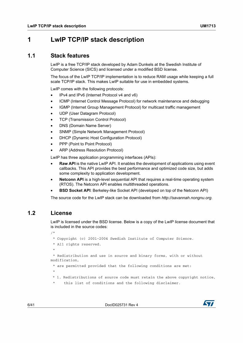
1.3 LwIP architecture
LwIP complies with the TCP/IP model architecture which specifies how data should be formatted, transmitted, routed and received to provide end-to-end communications.
This model includes four abstraction layers which are used to sort all related protocols according to the scope of networking involved (see Figure 1). From lowest to highest, the layers are:
• The link layer contains communication technologies for a single network segment (link) of a local area network.
• The internet layer (IP) connects independent networks, thus establishing internetworking.
• The transport layer handles host-to-host communications.
• The application layer contains all protocols for specific data communications services on a process-to-process level.
LwIP TCP/IP stack description UM1713
8/41 DocID025731 Rev 4
Figure 1. LwIP architecture
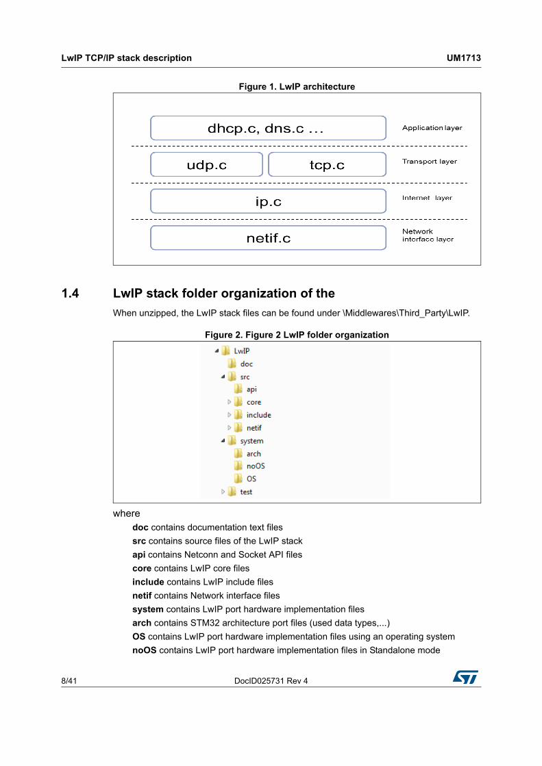
1.4 LwIP stack folder organization of the
When unzipped, the LwIP stack files can be found under \Middlewares\Third_Party\LwIP.
Figure 2. Figure 2 LwIP folder organization
wheredoc contains documentation text files
src contains source files of the LwIP stack
api contains Netconn and Socket API files
core contains LwIP core files
include contains LwIP include files
netif contains Network interface files
system contains LwIP port hardware implementation files
arch contains STM32 architecture port files (used data types,...)
OS contains LwIP port hardware implementation files using an operating system
noOS contains LwIP port hardware implementation files in Standalone mode
DocID025731 Rev 4 9/41
UM1713 LwIP TCP/IP stack description
40
1.5 LwIP API overview
As mentioned above, three types of APIs are offered by LwIP stack:
• Raw API
• Netconn API
• Socket API
1.5.1 Raw API
The Raw API is based on the native LwIP API. It is used to develop callback-based applications.
When initializing the application, the user needs to register callback functions to different core events (such as TCP_Sent, TCP_error,...). The callback functions are called from the LwIP core layer when the corresponding event occurs.
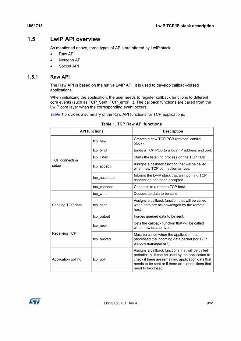
Table 1 provides a summary of the Raw API functions for TCP applications.
Table 1. TCP Raw API functions
API functions Description
TCP connection
setup
tcp_newCreates a new TCP PCB (protocol control block).
tcp_bind Binds a TCP PCB to a local IP address and port.
tcp_listen Starts the listening process on the TCP PCB
tcp_acceptAssigns a callback function that will be called when new TCP connection arrives.
tcp_acceptedInforms the LwIP stack that an incoming TCP connection has been accepted.
tcp_connect Connects to a remote TCP host.
Sending TCP data
tcp_write Queues up data to be sent.
tcp_sentAssigns a callback function that will be called when data are acknowledged by the remote host.
tcp_output Forces queued data to be sent.
Receiving TCP
tcp_recvSets the callback function that will be called when new data arrives.
tcp_recvedMust be called when the application has processed the incoming data packet (for TCP window management).
Application polling tcp_poll
Assigns a callback functions that will be called periodically. It can be used by the application to check if there are remaining application data that needs to be sent or if there are connections that need to be closed.

LwIP TCP/IP stack description UM1713
10/41 DocID025731 Rev 4
Table 2 provides a summary of the Raw API functions for UDP applications.
1.5.2 Netconn API
The Netconn API is a high-level sequential API which model of execution is based on the blocking open-read-write-close paradigm.
To operate correctly, this API must run in a multithreaded operating mode implementing a dedicated thread for the LwIP TCP/IP stack and/or multiple threads for the application.
Table 3 provides a summary of the Netconn API functions.
Closing and aborting connections
tcp_close Closes a TCP connection with a remote host.
tcp_errAssigns a callback function for handling connections aborted by the LwIP due to errors (such as memory shortage errors).
tcp_abort Aborts a TCP connection.
Table 2. UDP Raw API functions
API functions Description
udp_new Creates a new UDP PCB.
udp_remove Removes and de-allocates a UDP PCB.
udp_bind Binds a UDP PCB with a local IP address and port.
udp_connect Sets up a UDP PCB remote IP address and port.
udp_disconnect Removes a UDP PCB remote IP and port.
udp_send Sends UDP data.
udp_recv Specifies a callback function which is called when a datagram is received.
Table 1. TCP Raw API functions (continued)
API functions Description
Table 3. Netconn API functions
API functions Description
netconn_new Creates a new connection.
netconn_delete Deletes an existing connection.
netconn_bind Binds a connection to a local IP address and port.
netconn_connect Connects to a remote IP address and port.
netconn_sendSends data to the currently connected remote IP/port (not applicable for TCP connections).
netconn_recv Receives data from a netconn.

DocID025731 Rev 4 11/41
UM1713 LwIP TCP/IP stack description
40
1.5.3 Socket API
LwIP offers the standard BSD socket API. This is a sequential API which is internally built on top of the Netconn API.
Table 4 provides a summary of the main socket API functions.
1.6 LwIP buffer management
1.6.1 Packet buffer structure
LwIP manages packet buffers using a data structure called pbuf. The pbuf structure enables the allocation of a dynamic memory to hold a packet content and lets packets reside in the static memory.
Pbufs can be linked together in a chain, thus enabling packets to span over several pbufs.
netconn_listen Sets a TCP connection to a listening mode.
netconn_accept Accepts an incoming connection on a listening TCP connection.
netconn_write Sends data on a connected TCP netconn.
netconn_close Closes a TCP connection without deleting it.
Table 3. Netconn API functions (continued)
API functions Description
Table 4. Socket API functions
API functions Description
socket Creates a new socket.
bind Binds a socket to an IP address and port.
listen Listens for socket connections.
connect Connects a socket to a remote host IP address and port.
accept Accepts a new connection on a socket.
read Reads data from a socket.
write Writes data on a socket.
close Closes a socket (socket is deleted).

LwIP TCP/IP stack description UM1713
12/41 DocID025731 Rev 4
Figure 3. Pbuf structure
where
next contains the pointer to the next pbuf in a pbuf chain
payload contains the pointer to the packet data payload
len is the length of the data content of the pbuf
tot_len is the sum of pbuf len plus all the len fields of the next pbufs in the chain
ref is the 4-bit reference count that indicates the number of pointers that point to the pbuf. A pbuf can be released from memory only when its reference count is zero.
flags (on 4 bits) indicate the type of pbuf.
LwIP defines three types of pbufs, depending on the allocation type:
• PBUF_POOL
pbuf allocation is performed from a pool of statically preallocated pbufs of predefined size. Depending on the data size that needs to be allocated, one or multiple chained pbufs are required.
• PBUF_RAM
pbuf is dynamically allocated in memory (one contiguous chunk of memory for the full pbuf)
• PBUF_ROM
No memory space allocation is required for user payload: the pbuf payload pointer points to data in ROM memory that can be used only for sending constant data.
For packet reception, the suitable pbuf type is PBUF_POOL. It allows to quickly allocate memory for the packet received from the pool of pbufs. Depending on the size of the received packet, one or multiple chained pbufs are allocated. The PBUF_RAM is not suitable for packet reception because dynamic allocation takes some delay. It may also lead to memory fragmentation.
For packet transmission, the user can choose the most suitable pbuf type according to the data to be transmitted,.
1.6.2 pbuf management APIs
LwIP has a specific API for working with pbufs. This API is implemented in the pbuf.c core file.
DocID025731 Rev 4 13/41
UM1713 LwIP TCP/IP stack description
40
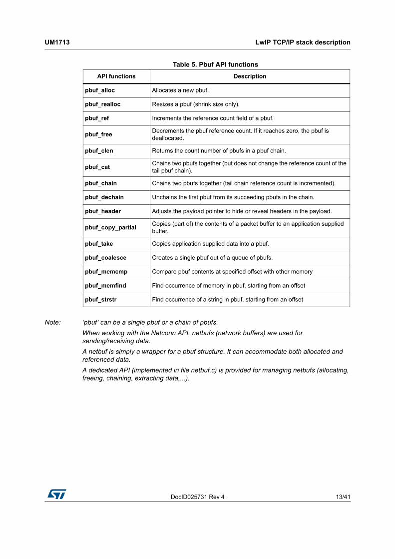
Note: ‘pbuf’ can be a single pbuf or a chain of pbufs.
When working with the Netconn API, netbufs (network buffers) are used for sending/receiving data.
A netbuf is simply a wrapper for a pbuf structure. It can accommodate both allocated and referenced data.
A dedicated API (implemented in file netbuf.c) is provided for managing netbufs (allocating, freeing, chaining, extracting data,...).
Table 5. Pbuf API functions
API functions Description
pbuf_alloc Allocates a new pbuf.
pbuf_realloc Resizes a pbuf (shrink size only).
pbuf_ref Increments the reference count field of a pbuf.
pbuf_freeDecrements the pbuf reference count. If it reaches zero, the pbuf is deallocated.
pbuf_clen Returns the count number of pbufs in a pbuf chain.
pbuf_catChains two pbufs together (but does not change the reference count of the tail pbuf chain).
pbuf_chain Chains two pbufs together (tail chain reference count is incremented).
pbuf_dechain Unchains the first pbuf from its succeeding pbufs in the chain.
pbuf_header Adjusts the payload pointer to hide or reveal headers in the payload.
pbuf_copy_partialCopies (part of) the contents of a packet buffer to an application supplied buffer.
pbuf_take Copies application supplied data into a pbuf.
pbuf_coalesce Creates a single pbuf out of a queue of pbufs.
pbuf_memcmp Compare pbuf contents at specified offset with other memory
pbuf_memfind Find occurrence of memory in pbuf, starting from an offset
pbuf_strstr Find occurrence of a string in pbuf, starting from an offset

Interfacing LwIP with STM32Cube Ethernet HAL driver UM1713
14/41 DocID025731 Rev 4
2 Interfacing LwIP with STM32Cube Ethernet HAL driver
This package includes two implementations:
• Implementation without operating system (standalone)
• Implementation with an operating system using CMSIS-RTOS API
For both implementations, the ethernetif.c file is used to link the LwIP stack to the STM32 Ethernet network interface.
The port of LwIP stack that must be connected to STM32F4xx is located in the “lwip/system” folder.
The Ethernet handle of the HAL (ETH_HandleTypeDef) should be declared in the ethernetif.c file, as well as the Ethernet DMA descriptors (ETH_DMADescTypeDef) and the Rx/Tx buffers of the Ethernet driver.
Table 6 provides a description of the LwIP interface API.
The following example shows how to initialize the Ethernet peripheral, using HAL API, into the interface API:
static void low_level_init(struct netif *netif)
{
uint8_t macaddress[6]= {MAC_ADDR0, MAC_ADDR1, MAC_ADDR2, MAC_ADDR3, MAC_ADDR4, MAC_ADDR5};
EthHandle.Instance = ETH;
EthHandle.Init.MACAddr = macaddress;
EthHandle.Init.AutoNegotiation = ETH_AUTONEGOTIATION_ENABLE;
EthHandle.Init.Speed = ETH_SPEED_100M;
EthHandle.Init.DuplexMode = ETH_MODE_FULLDUPLEX;
EthHandle.Init.MediaInterface = ETH_MEDIA_INTERFACE_MII;
EthHandle.Init.RxMode = ETH_RXINTERRUPT_MODE;
EthHandle.Init.ChecksumMode = ETH_CHECKSUM_BY_HARDWARE;
EthHandle.Init.PhyAddress = DP83848_PHY_ADDRESS;
Table 6. Ethernet interface functions description
Function Description
low_level_initCalls the Ethernet driver functions to initialize the STM32F4xx Ethernet peripheral
low_level_output Calls the Ethernet driver functions to send an Ethernet packet
low_level_input Calls the Ethernet driver functions to receive an Ethernet packet.
ethernetif_initInitializes the network interface structure (netif) and calls low_level_init to initialize the Ethernet peripheral
ethernet_inputCalls low_level_input to receive a packet then provide it to the LwIP stack
DocID025731 Rev 4 15/41
UM1713 Interfacing LwIP with STM32Cube Ethernet HAL driver
40
/* configure ethernet peripheral (GPIOs, clocks, MAC, DMA) */
HAL_ETH_Init(&EthHandle) ;
/* Initialize Tx Descriptors list: Chain Mode */
HAL_ETH_DMATxDescListInit(&EthHandle, DMATxDscrTab, &Tx_Buff[0][0], ETH_TXBUFNB);
/* Initialize Rx Descriptors list: Chain Mode */
HAL_ETH_DMARxDescListInit(&EthHandle, DMARxDscrTab, &Rx_Buff[0][0], ETH_RXBUFNB);
...
/* Enable MAC and DMA transmission and reception */
HAL_ETH_Start(&EthHandle);
}
The ethernet_input() function implementation differs between standalone and RTOS modes:
• In standalone applications, this function must be inserted into the main loop of the application to poll for any received packet.
• In RTOS applications, this function is implemented as a thread waiting for a semaphore to handle a received packet. The semaphore is given when the Ethernet peripheral generates an interrupt for a received packet.
The ethernetif.c file also implements the Ethernet peripheral MSP routines for low layer initialization (GPIO, CLK …) and interrupts callbacks.
In case of RTOS implementation, an additional file is used (sys_arch.c). This file implements an emulation layer for the RTOS services (message passing through RTOS mailbox, semaphores, etc.). This file should be tailored according to the current RTOS, that is FreeRTOS for this package.
LwIP configuration UM1713
16/41 DocID025731 Rev 4
3 LwIP configuration
LwIP provides a file named lwipopts.h that allows the user to fully configure the stack and all its modules. The user does not need to define all the LwIP options: if an option is not defined, a default value defined in opt.h file is used. Therefore, lwipopts.h provides a way to override much of the lwIP behavior.
3.1 Modules support
The user can choose the modules he needs for his application, so that the code size will be optimized by compiling only the selected features.
As an example, to disable UDP and enable DHCP, the following code must be implemented in lwipopts.h file:
/* Disable UDP */
#define LWIP_UDP 0
/* Enable DHCP */
#define LWIP_DHCP 1
3.2 Memory configuration
LwIP provides a flexible way to manage memory pool sizes and organization.
It reserves a fixed-size static memory area in the data segment. It is subdivided into the various pools that lwIP uses for the various data structures. As an example, there is a pool for struct tcp_pcb, and another pool for struct udp_pcb. Each pool can be configured to hold a fixed number of data structures. This number can be changed in the lwipopts.h file. For example, MEMP_NUM_TCP_PCB and MEMP_NUM_UDP_PCB define the maximum number of tcp_pcb and udb_pcb structures that can be active in the system at a given time.
The user options can be changed in lwipopts.h. Table 7 provides a summary of the main RAM memory options.
Table 7. LwIP memory configuration
LwIP memory option Definition
MEM_SIZELwIP heap memory size: used for all LwIP dynamic memory allocations.
MEMP_NUM_PBUF Total number of MEM_REF and MEM_ROM pbufs.
MEMP_NUM_UDP_PCB Total number of UDP PCB structures.
MEMP_NUM_TCP_PCB Total number of TCP PCB structures.
MEMP_NUM_TCP_PCB_LISTEN Total number of listening TCP PCBs.
MEMP_NUM_TCP_SEG Maximum number of simultaneously queued TCP segments.
PBUF_POOL_SIZE Total number of PBUF_POOL type pbufs.
DocID025731 Rev 4 17/41
UM1713 LwIP configuration
40
PBUF_POOL_BUFSIZE Size of a PBUF_POOL type pbufs.
TCP_MSS TCP maximum segment size.
TCP_SND_BUF TCP send buffer space for a connection.
TCP_SND_QUEUELEN Maximum number of pbufs in the TCP send queue.
TCP_WND Advertised TCP receive window size.
Table 7. LwIP memory configuration (continued)
LwIP memory option Definition

Developing applications with LwIP stack UM1713
18/41 DocID025731 Rev 4
4 Developing applications with LwIP stack
4.1 Developing in standalone mode using the Raw API
4.1.1 Operation model
In standalone mode, the operation model is based on continuous software polling to check if a packet has been received.
When a packet has been received, it is first copied from the Ethernet driver buffers into the LwIP buffers. To copy the packet as fast as possible, the LwIP buffers (pbufs) should be allocated from the pool of buffers (PBUF_POOL).
When a packet has been copied, it is handed to the LwIP stack for processing. Depending on the received packet, the stack may or may not notify the application layer.
LwIP communicates with the application layer using event callback functions. These functions should be assigned before starting the communication process.
Refer to Figure 4 for a description of the standalone operation model flowchart.
Figure 4. Standalone operation model
DocID025731 Rev 4 19/41
UM1713 Developing applications with LwIP stack
40
For TCP applications, the following common callback functions must be assigned:
• Callback for incoming TCP connection event, assigned by TCP_accept API call
• Callback for incoming TCP data packet event, assigned by TCP_recev API call
• Callback for signaling successful data transmission, assigned by TCP_sent API call
• Callback for signaling TCP error (after a TCP abort event), assigned by TCP_err API call
• Periodic callback (every 1 or 2 s) for polling the application, assigned by TCP_poll API call
4.1.2 Example of TCP echo server demonstration
The TCP echo server example provided in the \LwIP\LwIP_TCP_Echo_Server folder is a simple application that implements a TCP server which echoes any received TCP data packet coming from a remote client.
The following example provides a description of the firmware structure. This is an extract of the main.c file.
int main(void)
{
/* Reset of all peripherals, Initializes the Flash interface and the Systick. */
HAL_Init();
...
/* Initilaize the LwIP stack */
lwIP_init();
/* Network interface configuration */
Netif_Config();
...
/* tcp echo server Init */
tcp_echoserver_init();
/* Infinite loop */
while (1)
{
/* Read a received packet from the Ethernet buffers and send it
to the lwIP for handling */
ethernetif_input(&gnetif);
/* Handle LwIP timeouts */
sys_check_timeouts();
}
}
Developing applications with LwIP stack UM1713
20/41 DocID025731 Rev 4
The following functions are called:
1. HAL_Init function is called to reset all peripherals and to Initializes the Flash interface and the Systick timer
2. lwIP_init function is called to initialize the LwIP stack internal structures and start stack operations.
3. Netif_config function is called to configure the network interface (netif).
4. tcp_echoserver_init function is called to initialize the TCP echo server application.
5. ethernetif_input function in the infinite while loop polls for packet reception. When a packet is received, it is passed to be handled by the stack
6. sys_check_timeouts LwIP function is called to handle certain LwIP internal periodic tasks (protocol timers, retransmission of TCP packets...).
tcp_echoserver_init function description
The tcp_echoserver_init function code is the following:
void tcp_echoserver_init(void)
{
/* create new tcp pcb */
tcp_echoserver_pcb = tcp_new();
if (tcp_echoserver_pcb != NULL)
{
err_t err;
/* bind echo_pcb to port 7 (ECHO protocol) */
err = tcp_bind(tcp_echoserver_pcb, IP_ADDR_ANY, 7);
if (err == ERR_OK)
{
/* start tcp listening for echo_pcb */
tcp_echoserver_pcb = tcp_listen(tcp_echoserver_pcb);
/* initialize LwIP tcp_accept callback function */
tcp_accept(tcp_echoserver_pcb, tcp_echoserver_accept);
}
else
{
/* deallocate the pcb */
memp_free(MEMP_TCP_PCB, tcp_echoserver_pcb);
}
}
}
LwIP API calls tcp_new to allocate a new TCP protocol control block (PCB) (tcp_echoserver_pcb).
The allocated TCP PCB is bound to a local IP address and port using tcp_bind function.
DocID025731 Rev 4 21/41
UM1713 Developing applications with LwIP stack
40
After binding the TCP PCB, tcp_listen function is called in order to start the TCP listening process on the TCP PCB.
Finally a tcp_echoserver_accept callback function should be assigned to handle incoming TCP connections on the TCP PCB. This is done by using tcp_accept LwIP API function.
Starting from this point, the TCP server is ready to accept any incoming connection from remote clients.
tcp_echoserver_accept function description
The following example shows how incoming TCP connections are handled by tcp_echoserver_accept user callback function. This is an extract from this function.
static err_t tcp_echoserver_accept(void *arg, struct tcp_pcb *newpcb, err_t err)
{
...
/* allocate structure es to maintain tcp connection informations */
es = (struct tcp_echoserver_struct *)mem_malloc(sizeof(struct tcp_echoserver_struct));
if (es != NULL)
{
es->state = ES_ACCEPTED;
es->pcb = newpcb;
es->p = NULL;
/* pass newly allocated es structure as argument to newpcb */
tcp_arg(newpcb, es);
/* initialize lwIP tcp_recv callback function for newpcb */
tcp_recv(newpcb, tcp_echoserver_recv);
/* initialize lwIP tcp_err callback function for newpcb */
tcp_err(newpcb, tcp_echoserver_error);
/* initialize lwIP tcp_poll callback function for newpcb */
tcp_poll(newpcb, tcp_echoserver_poll, 1);
ret_err = ERR_OK;
...
}
Developing applications with LwIP stack UM1713
22/41 DocID025731 Rev 4
The following functions are called:
1. The new TCP connection is passed to tcp_echoserver_accept callback function through newpcb parameter.
2. An es structure is used to store the application status. It is passed as an argument to the TCP PCB “newpcb” connection by calling tcp_arg LwIP API.
3. A TCP receive callback function, tcp_echoserver_recv, is assigned by calling LwIP API tcp_recv. This callback handles all the data traffic with the remote client.
4. A TCP error callback function, tcp_echoserver_error, is assigned by calling LwIP API tcp_err. This callback handles TCP errors.
5. A TCP poll callback function, tcp_echoserver_poll, is assigned by calling LwIP API tcp_poll to handle periodic application tasks (such as checking if the application data remains to be transmitted).
4.2 Developing with an RTOS using Netconn or Socket API
4.2.1 Operation model
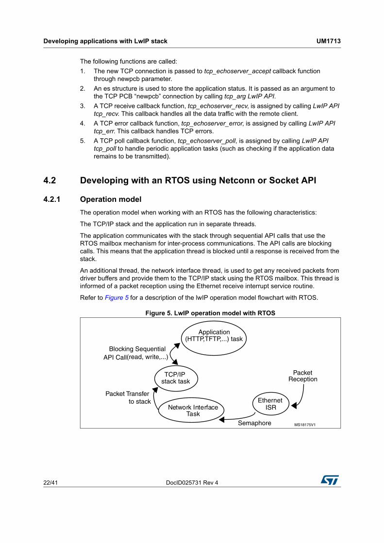
The operation model when working with an RTOS has the following characteristics:
The TCP/IP stack and the application run in separate threads.
The application communicates with the stack through sequential API calls that use the RTOS mailbox mechanism for inter-process communications. The API calls are blocking calls. This means that the application thread is blocked until a response is received from the stack.
An additional thread, the network interface thread, is used to get any received packets from driver buffers and provide them to the TCP/IP stack using the RTOS mailbox. This thread is informed of a packet reception using the Ethernet receive interrupt service routine.
Refer to Figure 5 for a description of the lwIP operation model flowchart with RTOS.
Figure 5. LwIP operation model with RTOS
DocID025731 Rev 4 23/41
UM1713 Developing applications with LwIP stack
40
4.2.2 Example of a TCP echoserver demonstration using the Netconn API
From the application point of view, the Netconn API offers a simpler way than the raw API for developing TCP/IP applications. This is because it has a more intuitive sequential API.
The following example shows a TCP echoserver application developed with the Netconn API. This is extract of the main.c file.
int main(void)
{
...
/* Create the Start thread */
osThreadDef(Start, StartThread, osPriorityNormal, 0, configMINIMAL_STACK_SIZE * 2);
osThreadCreate (osThread(Start), NULL);
/* Start the scheduler */
osKernelStart (NULL, NULL);
/* We should never get here as control is now taken by the scheduler */
for( ;; );
}
The start thread has the following code:
static void StartThread(void const * argument)
{
...
/* Create tcp_ip stack thread */
tcpip_init( NULL, NULL );
/* Network interface configuration */
Netif_Config();
/* Initialize tcp echo server */
tcpecho_init();
for( ;; )
{
}
}
The following functions are called:
1. tcpip_init function is called to initialize the LwIP stack modules and to start the TCP/IP stack thread.
2. Netif_config function is called to configure the network interface (netif).3. The TCP echo server thread is created in tcpecho_init function.

Developing applications with LwIP stack UM1713
24/41 DocID025731 Rev 4
void tcpecho_init(void)
{
sys_thread_new("tcpecho_thread", tcpecho_thread, NULL, DEFAULT_THREAD_STACKSIZE, TCPECHO_THREAD_PRIO);
}
tcpecho_thread function description
The TCP echo server thread has the following code:
static void tcpecho_thread(void *arg)
{
/* Create a new connection identifier. */
conn = netconn_new(NETCONN_TCP);
if (conn!=NULL)
{
/* Bind connection to well known port number 7. */
err = netconn_bind(conn, NULL, 7);
if (err == ERR_OK)
{
/* Tell connection to go into listening mode. */
netconn_listen(conn);
while (1)
{
/* Grab new connection. */
accept_err = netconn_accept(conn, &newconn);
/* Process the new connection. */
if (accept_err == ERR_OK)
{
while (( recv_err = netconn_recv(newconn, &buf)) == ERR_OK)
{
do
{
netbuf_data(buf, &data, &len);
netconn_write(newconn, data, len, NETCONN_COPY);
}
while (netbuf_next(buf) >= 0);
netbuf_delete(buf);
}
/* Close connection and discard connection identifier. */
netconn_close(newconn);
netconn_delete(newconn);
DocID025731 Rev 4 25/41
UM1713 Developing applications with LwIP stack
40
}
}
}
else
{
netconn_delete(newconn);
}
}
}
The following sequence is executed:
1. Netconn_new API function is called with NETCONN_TCP parameter will create a new TCP connection.
2. The newly created connection is then bound to port 7 (echo protocol) by calling Netconn_bind API function.
3. After binding the connection, the application starts monitoring the connection by calling Netconn_listen API function.
4. In the infinite while(1) loop, the application waits for a new connection by calling the API function Netconn_accept. This API call blocks the application task when there is no incoming connection.
5. When there is an incoming connection, the application can start receiving data by calling netconn_recv API function. Incoming data is received in a netbuf.
6. The application can get the received data by calling netbuf_data netbuf API function.
7. The received data is sent back (echoed) to the remote TCP client by calling Netconn_write API function.
8. Netconn_close and Netconn_delete are used to close and delete the Netconn connection, respectively.
LwIP package description UM1713
26/41 DocID025731 Rev 4
5 LwIP package description
5.1 LwIP package directories
The package contains a set of applications running on top of the LwIP stack and STM32Cube HAL and BSP drivers. The firmware is composed from the following modules:
• Drivers: contains the low level drivers of STM32F4xx microcontroller
– CMSIS
– BSP drivers
– HAL drivers
• Middlewares: contains libraries and protocol components
– LwIP TCP/IP stack
– FatFS
– FreeRTOS
• Projects: contains the source file and configurations of the following applications:
– Applications running in standalone mode (without an RTOS) based on Raw API:
A Web server
A TFTP server
A TCP echo client application
A TCP echo server application
A UDP echo client application
A UDP echo server application
– Applications running with the FreeRTOS operating system:
A Web server based on netconn API
A Web server based on socket API
A TCP/UDP echo server application based on netconn API.
Applications are located under Projects repository following this path: Projects\STM324xx_EVAL\Applications\LwIP\, where STM324xx_EVAL refers to STM32F4xx evaluation board such as STM324xG_EVAL for STM32F407xx/417xx devices.
5.2 Applications settings
5.2.1 PHY interface configuration
The Ethernet peripheral is interfaced with an external PHY to provide physical layer communications. The PHY registers definition and define statements are located in the HAL configuration file stm32f4xx_hal_conf.h.
The PHY can operates in MII or RMII mode. To select the required mode, fill the MediaInterface parameter in Init structure when initializing the Ethernet peripheral.
Note: Refer to the readme file provided within your device Ethernet examples to know more about the available PHY interface modes on the supported boards.
DocID025731 Rev 4 27/41
UM1713 LwIP package description
40
5.2.2 MAC and IP address settings
The default MAC address is set to 00:00:00:00:00:02. To change this address, modify the six bytes defined in the stm32f4xx_hal_conf.h file.
The default IP address is set to: 192.168.0.10. To change this address, modify the four bytes defined in the main.h file.
5.2.3 Firmware features
This package includes modules to enhance and widen the use of the some applications.
The DHCP protocol is supported so that the STM32 MCU can act as a DHCP client to get a dynamic IP address when it is connected to a DHCP server. To enable DHCP protocol, uncomment the following macro:
#define USE_DHCP” from main.h file.
Note: If the IP address is configured by DHCP and the application does not find a DHCP server on the network to which it is already connected, the IP address is then automatically set to the static address (192.168.0.10).
The user can enable the LCD controller by defining the #define USE_LCD macro in main.h. If it is enabled, text messages will be displayed to inform the user of the status of the application (assigned IP address, network link status …)
Note: Getting started applications do not support DHCP and LCD modules. Refer to Section 6: Using the LwIP applications for more information.
5.3 Evaluation boards settings
Before running an Ethernet example, read the corresponding readme file to know how to configure the board jumper to ensure correct operation.
Using the LwIP applications UM1713
28/41 DocID025731 Rev 4
6 Using the LwIP applications
The STM32Cube LwIP package comes with several applications that use the different LwIP stack API sets.
The applications are divided into three categories as shown in Table 8.
Getting started applications use the minimal configuration to run applications on top of the LwIP stack. LEDs are used to inform the user of application status.
Features applications provide more flexibility and options. They support network protocols like HTTP, DHCP and use LCD messages to indicate application status.
Integrated application supports FatFS middleware component and TFTP protocol to transfer files to and from microSD™ card located on the evaluation board.
6.1 Getting started applications
6.1.1 TCP echo client
This application is used to test a basic TCP connection. The STM32 MCU acts as a TCP client that connects to the TCP server. The client sends a string and the server echoes back the same string to the client.
To test the TCP echo client application, follow these steps:
1. Make sure the STM324xx-EVAL jumper settings are correct.
2. Build and program the demonstration code into the STM32F4xx Flash memory.
LEDs indicates the LwIP initialization success or failure (the dynamic address allocation “DHCP” is not supported for this application).
3. On the remote PC, open a command prompt window. Under Windows, select Start > All Programs > Accessories > Command Prompt.
Table 8. LwIP applications categories
Categories Applications
Getting started (basic)
TCP Echo client
TCP Echo server
UDP Echo client
UDP Echo server
TCP and UDP Echo server (Netconn API)
Features
HTTP Server (Raw API)
HTTP Server (Netconn API)
HTTP Server (Socket API)
Integrated TFTP Server

DocID025731 Rev 4 29/41
UM1713 Using the LwIP applications
40
4. At the command prompt, enter:
C:\>echotool /p tcp /s
where:
– /p tcp is the TCP protocol (TCP protocol)
– /s is the actual mode of connection (Server mode)
5. When the Key button is pressed on the STM324xx-EVAL board, the client sends a string and the server echoes back the same string to the client.
Note: Make sure the remote PC IP address is identical to the address defined in the main.h file (192.168.0.11 by default).
Figure 6 shows an example of this command string and of the module response.
Figure 6. TCP echo client
6.1.2 TCP Echo server
This application is used to test a basic TCP connection. The STM32 MCU acts as a TCP server that waits for client requests. It simply echoes back whatever is sent.
To test the TCP echo server demo, follow these steps:
1. Make sure of the STM324xx-EVAL jumper settings are correct.
2. Build and program the demonstration code into the STM32F4xx Flash memory.
LEDs indicates the LwIP initialization success or failure (the dynamic address allocation “DHCP” is not supported for this application).
3. On the remote PC, open a command prompt window. Under Windows, select Start > All Programs > Accessories > Command Prompt.
Using the LwIP applications UM1713
30/41 DocID025731 Rev 4
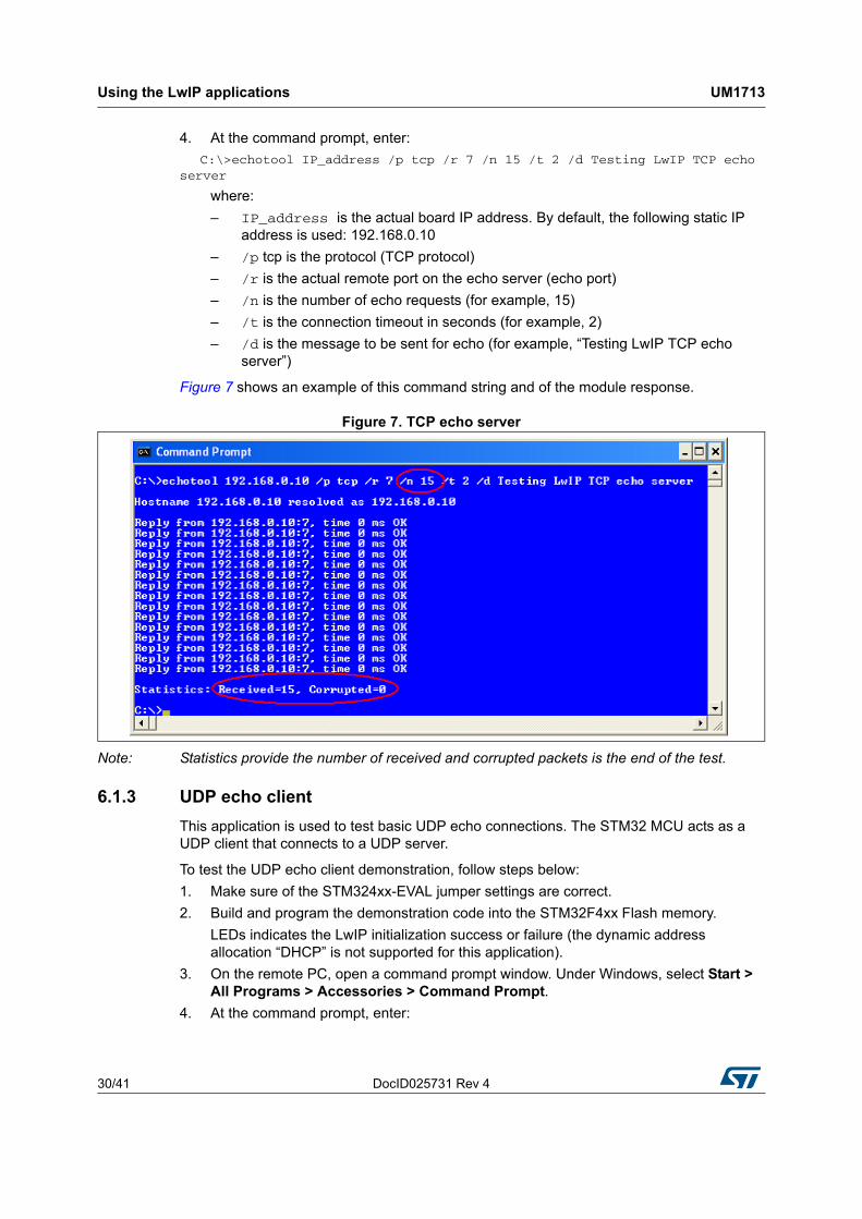
4. At the command prompt, enter:
C:\>echotool IP_address /p tcp /r 7 /n 15 /t 2 /d Testing LwIP TCP echo server
where:
– IP_address is the actual board IP address. By default, the following static IP address is used: 192.168.0.10
– /p tcp is the protocol (TCP protocol)
– /r is the actual remote port on the echo server (echo port)
– /n is the number of echo requests (for example, 15)
– /t is the connection timeout in seconds (for example, 2)
– /d is the message to be sent for echo (for example, “Testing LwIP TCP echo server”)
Figure 7 shows an example of this command string and of the module response.
Figure 7. TCP echo server
Note: Statistics provide the number of received and corrupted packets is the end of the test.
6.1.3 UDP echo client
This application is used to test basic UDP echo connections. The STM32 MCU acts as a UDP client that connects to a UDP server.
To test the UDP echo client demonstration, follow steps below:
1. Make sure of the STM324xx-EVAL jumper settings are correct.
2. Build and program the demonstration code into the STM32F4xx Flash memory.
LEDs indicates the LwIP initialization success or failure (the dynamic address allocation “DHCP” is not supported for this application).
3. On the remote PC, open a command prompt window. Under Windows, select Start > All Programs > Accessories > Command Prompt.
4. At the command prompt, enter:

DocID025731 Rev 4 31/41
UM1713 Using the LwIP applications
40
C:\>echotool /p udp /s
where:
– /p udp is the protocol (UDP protocol)
– /s is the actual mode of connection (Server mode)
5. When the Key button is pressed on the STM324xx-EVAL board, the client sends a string and the server echoes back the same string to the client.
Note: Make sure that the remote PC IP address is identical to the address defined in the main.h file (192.168.0.11 by default).
Figure 8 shows an example of this command string and of the module response.
Figure 8. UDP echo client
6.1.4 UDP echo server
This application is used to test basic UDP connections. The STM32 MCU acts as a UDP server that waits for client requests.
To test the UDP echo server application, follow these steps:
1. Make sure of the STM324xx-EVAL jumper settings are correct.
2. Build and program the demonstration code into the STM32F4xx Flash memory.
LEDs indicates the LwIP initialization success or failure (the dynamic address allocation “DHCP” is not supported for this application).
3. On the remote PC, open a command prompt window. Under Windows, select Start > All Programs > Accessories > Command Prompt.
4. At the command prompt, enter:

Using the LwIP applications UM1713
32/41 DocID025731 Rev 4
C:\>echotool IP_address /p udp /r 7 l/ 7 /n 15 /t 2 /d Testing LwIP UDP echo server
where:
– IP_address is the actual board IP address. By default, the following static IP address is used: 192.168.0.10
– /p is the protocol (UDP protocol)
– /r is the actual remote port on the echo server (echo port)
– /l is the actual local port for the client (echo port)
– /n is the number of echo requests (for example, 15)
– /t is the connection timeout in seconds (for example, 2)
– /d is the message to be sent for echo (for example, “Testing LwIP UDP echo server”)
Figure 9 shows an example of this command string and of the module response.
Figure 9. UDP echo server
Note: Statistics providing the number of received and corrupted packets are given at the end of the test.
6.1.5 UDP TCP echo server based on netconn AP
This demonstration provides the echo service application both for TCP and UDP protocols:
• To test the UDP TCP echo server netconn demonstration in TCP server mode, refer to Section 6.1.2: TCP Echo server.
• To test the UDP TCP echo server netconn demonstration in UDP server mode, refer to Section 6.1.4: UDP echo server.
DocID025731 Rev 4 33/41
UM1713 Using the LwIP applications
40
6.2 Features applications
6.2.1 Web server based on raw API
This application implements a web server based on the LwIP raw API. It is used to connect to the STM32 MCU from a web client and to load HTML pages.
The web server application implements the following features:
• URL parsing
• CGI (Common Gateway Interface)
• SSI (Server Side Includes)
• Dynamic Header generation
• HTTP Post request
To test the web server application, follow these steps:
1. Make sure of the STM324xx-EVAL jumper settings are correct.
2. In the main.h file, uncomment “USE_DHCP” or “USE_LCD” options to enable the DHCP client or LCD screen features.
3. Build and program the application code into the STM32F4xx Flash memory.
4. If “USE_ DHCP” and “USE_LCD” are defined, a message is displayed on the LCD screen to indicate the success or failure of the DHCP IP address allocation, otherwise the LEDs indicate the result of this operation.
5. After an IP address has been assigned (either a static or a dynamic address), the user can start the application.
6. On the remote PC, open a web client (Mozilla Firefox or Internet Explorer) and type the board IP address in a web browser. By default, the following static IP address is used: 192.168.0.10.
Using the LwIP applications UM1713
34/41 DocID025731 Rev 4
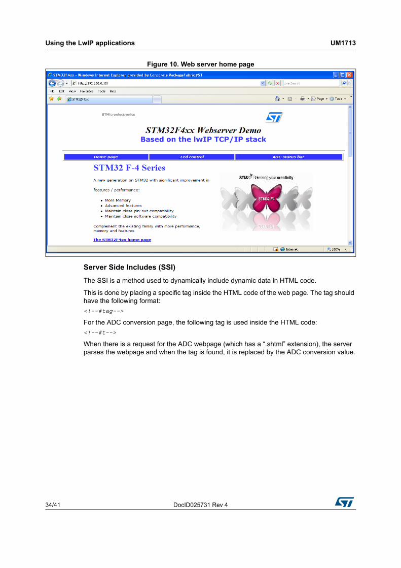
Figure 10. Web server home page
Server Side Includes (SSI)
The SSI is a method used to dynamically include dynamic data in HTML code.
This is done by placing a specific tag inside the HTML code of the web page. The tag should have the following format:
<!--#tag-->
For the ADC conversion page, the following tag is used inside the HTML code:
<!--#t-->
When there is a request for the ADC webpage (which has a “.shtml” extension), the server parses the webpage and when the tag is found, it is replaced by the ADC conversion value.

DocID025731 Rev 4 35/41
UM1713 Using the LwIP applications
40
Figure 11. SSI use in HTTP server
Common Gateway Interface (CGI)
The CGI is a standard web technique used to execute a request coming from a client on the server side and then to return a response to the client.
In LwIP, the CGI offered works only with GET method requests and can handle up to 16 parameters encoded in the URI. The CGI handler function executed on the server side returns a HTML file that the HTTP server sends to the client.
In the HTTP server demonstration, this method is used to control the four LEDs (LED1, LED2, LED3 and LED4) of the evaluation board.
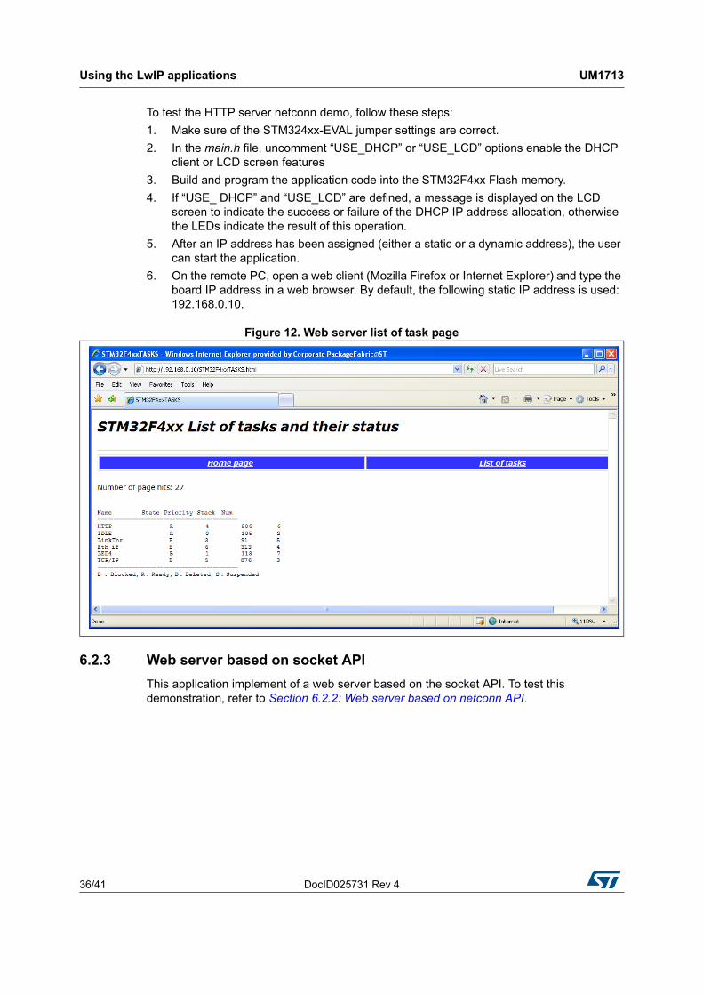
6.2.2 Web server based on netconn API
This application implement of a web server based on the netconn API. It is used to connect to the STM32 MCU from a web client and to load HTML pages.
This web server contains two HTML pages. The first one gives general information about STM32F4xx microcontrollers and the LwIP stack. The second one lists the running tasks and their status. This page is automatically updated every second (see Figure 12).
Using the LwIP applications UM1713
36/41 DocID025731 Rev 4
To test the HTTP server netconn demo, follow these steps:
1. Make sure of the STM324xx-EVAL jumper settings are correct.
2. In the main.h file, uncomment “USE_DHCP” or “USE_LCD” options enable the DHCP client or LCD screen features
3. Build and program the application code into the STM32F4xx Flash memory.
4. If “USE_ DHCP” and “USE_LCD” are defined, a message is displayed on the LCD screen to indicate the success or failure of the DHCP IP address allocation, otherwise the LEDs indicate the result of this operation.
5. After an IP address has been assigned (either a static or a dynamic address), the user can start the application.
6. On the remote PC, open a web client (Mozilla Firefox or Internet Explorer) and type the board IP address in a web browser. By default, the following static IP address is used: 192.168.0.10.
Figure 12. Web server list of task page
6.2.3 Web server based on socket API
This application implement of a web server based on the socket API. To test this demonstration, refer to Section 6.2.2: Web server based on netconn API.

DocID025731 Rev 4 37/41
UM1713 Using the LwIP applications
40
6.3 Integrated applications
6.3.1 TFTP server
The TFTP server is a file transfer application that requires a remote TFTP client. The files are transferred to and from the microSD card located on the STM324xx-EVAL board.
The TFTP server waits for a request from a remote TFTP client. The STM324xx-EVAL evaluation board must be connected through a remote PC to download or upload a file. To do this, a TFTP client must be installed on the remote PC. This can be done by using the tftpd32 tool which can be found at http://tftpd32.jounin.net.
To test the TFTP server application, follow these steps:
1. Make sure of the STM324xx-EVAL jumper settings are correct.
2. In the main.h file, uncomment “USE_DHCP” or “USE_LCD” options to enable the DHCP client or LCD screen features.
3. Build and program the application code into the STM32F4xx Flash memory.
4. If “USE_ DHCP” and “USE_LCD” are defined, a message is displayed on the LCD screen indicating the success or failure of the DHCP IP address allocation, otherwise the LEDs indicate the result of this operation
5. After an IP address has been assigned (either a static or a dynamic address), the user can start the application.
6. On the remote PC, open the TFTP client (for example, TFTPD32), and configure the TFTP server address (host address in TFTPD32).
7. Start transferring files to and from the micro SD card located on the STM324xx-EVAL board.
Figure 10 gives an overview of the tftpd32 tool.
Figure 13. TFTP tool (tftpd32)
Note: Make sure that the microSD card is plugged into the dedicated connector prior to downloading/uploading a file from/to the STM324xx-EVAL board.

Conclusion UM1713
38/41 DocID025731 Rev 4
7 Conclusion
LwIP package allows to use lwIP TCP/IP stack with the STM32Cube HAL API. This open source stack offers the services of a full-scale TCP/IP stack while keeping relatively low RAM/ROM usage.
Two approaches are described for developing TCP/IP applications, either in a Standalone mode, or using a real-time operating system (RTOS) for multi-threaded operations.

DocID025731 Rev 4 39/41
UM1713 FAQ
40
Appendix A FAQ
A.1 How do I choose between static or dynamic (DHCP) IP address allocation?
When the macro #define USE_DHCP located in main.h is commented, a static IP address is assigned to the STM32 microcontroller (by default 192.168.0.10, this value can be modified from “main.h” file).
If the macro #define USE_DHCP is uncommented, the DHCP protocol is enabled, and the STM32 will act as a DHCP client
A.2 How does the application behave when the Ethernet cable is disconnected?
When the cable is disconnected the Ethernet peripheral stops both transmission and reception traffics and the network interface is shut down. If an LCD controller is used, a message is displayed to inform the user that the cable is not connected, otherwise the red LED of the evaluation board is switched on.
When the user re-connects the cable, the Ethernet traffic resumes and the network interface is set up. If an LCD controller is used, a message is displayed to inform the user of the new IP address either with static or dynamic allocation, otherwise the yellow LED of the evaluation board is switched on.
A.3 How can the application be ported on a different hardware?
When another hardware platform is used, check the GPIO configuration in the HAL_ETH_MspInit() function for the Ethernet peripheral and in HAL_PPP_MspInit() or HAL_MspInit() if the application needs more PPP peripheral.
Revision history UM1713
40/41 DocID025731 Rev 4
8 Revision history
Table 9. Document revision history
Date Revision Changes
28-Mar-2014 1 Initial release.
14-Nov-2014 2Updated Figure 1: STM32Cube block diagram.
Updated Table 1: TCP Raw API functions and Table 3: Netconn API functions.
05-Feb-2015 3 Updated Section : Introduction.
27-May-2015 4
Updated Section : Introduction and merged with section STM32Cube overview.
Changed STM32F4xx/STM32F2x7xx into STM32F4xx in the whole document and removed STM322xG-EVAL board.
Updated Section 5.1: LwIP package directories.
Removed note related to RMII mode and added note concerning related boards in Section 5.2.1: PHY interface configuration.
Removed dedicated evaluation board settings sections in Section 5.2: Applications settings.

DocID025731 Rev 4 41/41
UM1713
41
IMPORTANT NOTICE – PLEASE READ CAREFULLY
STMicroelectronics NV and its subsidiaries (“ST”) reserve the right to make changes, corrections, enhancements, modifications, and improvements to ST products and/or to this document at any time without notice. Purchasers should obtain the latest relevant information on ST products before placing orders. ST products are sold pursuant to ST’s terms and conditions of sale in place at the time of order acknowledgement.
Purchasers are solely responsible for the choice, selection, and use of ST products and ST assumes no liability for application assistance or the design of Purchasers’ products.
No license, express or implied, to any intellectual property right is granted by ST herein.
Resale of ST products with provisions different from the information set forth herein shall void any warranty granted by ST for such product.
ST and the ST logo are trademarks of ST. All other product or service names are the property of their respective owners.
Information in this document supersedes and replaces information previously supplied in any prior versions of this document.
© 2015 STMicroelectronics – All rights reserved


![User Datagram Protocol (UDP) UDP [RFC 768] UDP Socket](https://static.fdocuments.us/doc/165x107/586e022b1a28ab3c168b57c2/user-datagram-protocol-udp-udp-rfc-768-udp-socket.jpg)