ULTRA OVAL GENERAL SPECIFICATION - dnh … · Description Local LCD only 4 ~ 20 mADC Refer to...
12
ULTRA OVAL METER SIZES: 39, 41, 45, 50, 52, 53, 55, 56, 57 Register Type A and B GENERAL SPECIFICATION GS.No.GBU005-6-E Head Office: Tokyo; Tel. 81-3-3360-5121. Fax 81-3-3365-8605 Beijing Office: Tel., Fax. 86-10-6525-3601. Tel. 86-10-6513-3516 Overseas Branch Offices: Seoul. Singapore. Taipei OVAL Corporation http://www.oval.co.jp ■ GENERAL Our workhorse PD flowmeter series is redesigned in this ULTRA OVAL with the most advanced multi-function electronic register (ULTRA register) capable of indicating the instantaneous flowrate and total flow on an easy-to-read LCD and of providing the pulse and analog output. Significantly improved performance along with compact and lightweight design are among the many benefits it offers. ■ FEATURES 1. Flow range expanded by 10 to 90% (over the previously offered OVAL meters of the same sizes). 2. Absence of mechanical reduction gear train combined with special carbon bearings contributes to low pressure loss and long life. 3. Thanks to pocketless design, the process fluid is virtually free from stagnation in the measuring chamber-beneficial to a broad range of fluids, particularly chemicals and foods. 4. Microprocessor-based ULTRA register indicates variables-total flow, both resettable and cumulative, instantaneous flowrate, selectable with mode select switch, plus alarm (low battery alarm) on the LCD. 5. Output signal is available in two channels simultaneously in the form of total flow (4/20mA DC factored or unfactored current pulses) and instan- taneous flowrate signal (4~20mA DC analog). 6. A complete series of explosionproof models also available. 7. We also manufacture models approved for applicable high-pressure gas control law. Meter size 57 Meter sizes 55, 56 Meter sizes 50, 52, 53 Meter sizes 39, 41, 45 Item Meter size Nominal size Flange rating 1 group 3 group Flow range Standard Low High Jacketed Linearity Repeatability Body Rear cover Rotors Bearings Shafts Jacketed Connection Max. operating press. Flow direction Materials ■ GENERAL SPECIFICATIONS ● Meter Body Flange group Temp. JIS 10K RF ANSI/JPI 150 RF JIS 20K RF JIS 30K RF ANSI/JPI 300 RF Max. 120˚C 1.18 1.51 –––– –––– –––– 1 Max. 200˚C 1.18 1.25 –––– –––– –––– Max. 350˚C –––– –––– –––– –––– –––– Max. 120˚C –––– –––– 2.45 2.94 2.94 3 Max. 200˚C –––– –––– 1.7 1.7 1.7 Max. 350˚C –––– –––– 1.5 1.5 1.5 Applies to body material code C. For body material code E, consult the factory. ●Flange Rating and Max. Operating Pressure (MPa) Description 39 41 45 50 52 53 55 56 57 10mm 20mm 25mm 40mm 50mm JIS 10K RF, ANSI/JPI 150 RF JIS 16, 20, 30K RF, ANSI/JPI 300 RF, DIN 10, 16, 20, 25 See flow range tables (page 3). –10~+120˚C ––––––––––– –60~+60˚C ––––––––––– 120~200˚C 120~350˚C ––––––––––– –––––––– 120~350˚C ±0.35% or ±0.15% ±0.05% or ±0.02% SCS14 or ✽SCS16 SUS316 or ✽SUS316L 39:Special carbon only, 41~57: SUS316 or ✽SUS316L 39:Special carbon only, 41~57: Special carbon or ceramics SUS316 or ✽SUS316L ––––––––––– Rc 1 / 2 Rc 3 / 4 ––––––––––– 0.98MPa Right left (standard), left right, bottom top, top bottom ✽Special Operating temperature range
Transcript of ULTRA OVAL GENERAL SPECIFICATION - dnh … · Description Local LCD only 4 ~ 20 mADC Refer to...

ULTRA OVALMETER SIZES: 39, 41, 45, 50, 52, 53, 55, 56, 57
Register Type A and B
GENERAL SPECIFICATION
GS.No.GBU005-6-E
Head Office: Tokyo; Tel. 81-3-3360-5121. Fax 81-3-3365-8605 Beijing Office: Tel., Fax. 86-10-6525-3601. Tel. 86-10-6513-3516Overseas Branch Offices: Seoul. Singapore. Taipei
OVAL Corporation http://www.oval.co.jp
GENERALOur workhorse PD flowmeter series is redesigned in thisULTRA OVAL with the most advanced multi-functionelectronic register (ULTRA register) capable ofindicating the instantaneous flowrate and total flow onan easy-to-read LCD and of providing the pulse andanalog output. Significantly improved performancealong with compact and lightweight design are amongthe many benefits it offers.
FEATURES1. Flow range expanded by 10 to 90% (over the
previously offered OVAL meters of the same sizes).2. Absence of mechanical reduction gear train combined
with special carbon bearings contributes to lowpressure loss and long life.
3. Thanks to pocketless design, the process fluid isvirtually free from stagnation in the measuringchamber-beneficial to a broad range of fluids,particularly chemicals and foods.
4. Microprocessor-based ULTRA register indicatesvariables-total flow, both resettable and cumulative,instantaneous flowrate, selectable with mode selectswitch, plus alarm (low battery alarm) on the LCD.
5. Output signal is available in two channelssimultaneously in the form of total flow (4/20mA DCfactored or unfactored current pulses) and instan-taneous flowrate signal (4~20mA DC analog).
6. A complete series of explosionproof models alsoavailable.
7. We also manufacture models approved for applicablehigh-pressure gas control law.
Meter size 57
Meter sizes 55, 56
Meter sizes 50, 52, 53
Meter sizes 39, 41, 45
Item
Meter sizeNominal size
Flange rating1 group3 group
Flow rangeStandardLowHighJacketed
LinearityRepeatability
BodyRear coverRotorsBearingsShafts
JacketedConnectionMax. operating press.
Flow direction
Mat
eria
ls
GENERAL SPECIFICATIONS Meter Body
Flange group Temp. JIS 10K RF ANSI/JPI 150 RF JIS 20K RF JIS 30K RF ANSI/JPI 300 RFMax. 120˚C 1.18 1.51 –––– –––– ––––
1 Max. 200˚C 1.18 1.25 –––– –––– ––––Max. 350˚C –––– –––– –––– –––– ––––Max. 120˚C –––– –––– 2.45 2.94 2.94
3 Max. 200˚C –––– –––– 1.7 1.7 1.7Max. 350˚C –––– –––– 1.5 1.5 1.5
Applies to body material code C. For body material code E, consult the factory.
Flange Rating and Max. Operating Pressure (MPa)
Description39 41 45 50 52 53 55 56 57
10mm 20mm 25mm 40mm 50mm
JIS 10K RF, ANSI/JPI 150 RF
JIS 16, 20, 30K RF, ANSI/JPI 300 RF, DIN 10, 16, 20, 25
See flow range tables (page 3).
–10~+120˚C––––––––––– –60~+60˚C
––––––––––– 120~200˚C 120~350˚C
––––––––––– –––––––– 120~350˚C
±0.35% or ±0.15%
±0.05% or ±0.02%
SCS14 or SCS16
SUS316 or SUS316L
39:Special carbon only, 41~57: SUS316 or SUS316L
39:Special carbon only, 41~57: Special carbon or ceramics
SUS316 or SUS316L
––––––––––– Rc 1/2 Rc 3/4––––––––––– 0.98MPa
Right left (standard), left right, bottom top, top bottom
Special
Operating
temperature
range
Description
Local LCD only
4 ~ 20 mADC Refer to diagram, page 6.
Scaled or unscaled: 0/1=4/20 mADC
Scaled: 1ms (std.), 50 ms Unscaled: 2ms
Same as of LCD counter 1Scaled or unscaled: NPN transister output: Max. impressed voltage 30 VDC
allowable current: 50 mA,transister on voltage: 1.5VDC and below
Scaled: 1ms (std.), 50 ms Unscaled: 2ms
Same as of LCD counter 1
Scaled or unscaled: [0]1 VDC Max. [1]7 VDC Min.
Scaled: 1ms (std.), 50 ms Unscaled: 2ms
Same as of LCD counter 1
Installed lithium battery Life: 8 yearsExternal power source: 12 ~ 45 VDC (analog or current pulse)
12 ~ 24 VDC (open collector pulse or voltage pulse)12 ~ 45 VDC (combination analog and current pulse)
Current consumption: Max. 30 mADC Refer to diagram in page 6. ( 2)Captyre cable w/external shield
(VCTF 1.25 mm2, finished O. D. 8.5 ~ 12mm) ( 3)
Max.1km
Analog or current pulse
Open collector or voltage pulse
Analog + current pulse
–10 ~ +60˚C
Select either one from following two
① Non-explosionproof type
② Explosionproof type: ExdIIBT4 / ExiaIIBT4
IP66 (Dust-tight/Watertight Type)-IEC/EN60529, JIS C 0920
Aluminum die casting
Munsell No. 2.5PB5/8 (baked melamine)
2
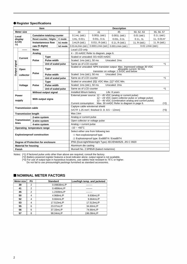
Register Specifications
ItemMeter size
Cumulative totalizing counterReset counter, 7digits C mode
Instantaneous flow b1 mode
rate (5 digits) b2 mode
—— NoneAnalog
TypeCurrentPulse Pulse width
Unit of scaled pulse
Open Type
collectorPulse Pulse width
Unit of scaled pulseType
Voltage Pulse Pulse widthUnit of scaled pulse
Without output signalPower
With output signasupply
Transmission cable
Transmission length2-wire system
Transmission 3-wire systemlines 4-wire systemOperating temperature range
Explosionproof construction
Degree of Protection for enclosureMaterial for housingFinish
Notes: ( 1) If factored pulse units other than above are required, consult the factory.( 2) Battery powered register features a local indicator alone; output signal is not available.( 3) For use of output type in hazardous locations, use cables heat resistant to 75˚C or higher.
Do not fail to use pressuretight packings furnished as standard accessories.
Localdisplay(LCD) 1
0.1mL (std.)
1mL, 0.01L
1mL/h (std.)
0.01mL/min (std.)
0.001L (std.)
0.01L, 0.1L
0.01L /h (std.)
0.0001L/min (std.)
0.01 (std.)
0.1L, 1L
1L /h (std.)
0.1L (std.)
1L, 0.01m3
1L /h (std.)
39 41 50, 52, 53 55, 56, 57
Meter size P/r Standard39 2 0.09838 mL/P –––––
41 2 0.4896 mL/P –––––
45 2 1.2339 mL/P –––––
50 4 4.968 mL/P 9.936 mL/P
52 4 9.664 mL/P 9.664 mL/P
53 4 17.513 mL/P 17.513 mL/P
55 6 23.07 mL/P 34.60 mL/P
56 6 37.33 mL/P 74.66 mL/P
57 8 98.04 mL/P 196.08 mL/P
NOMINAL METER FACTORS
Low/high temp. and jacketed
0.01 L/min (std.)
0.001L (std.)
0.01L, 0.1L
0.1L /h (std.)
0.001L/min (std.)
45
Ou
tpu
t si
gn
al

3
1. Linearity: ±0.35%Operating temp. range: –10~+120˚C (std.)
Viscosity Less than 0.3mPa·s 0.8mPa·s 2mPa·s 5mPa·s~Meter size 0.3mPa·s ~0.8mPa·s ~2mPa·s ~5mPa·s 1000mPa·s
50 0.3~1.6 0.15~1.6 0.1 ~1.6 0.05~ 2 0.03 ~ 2
52 0.7~3 0.4 ~3 0.3 ~3 0.15~ 3.8 0.08 ~ 3.8
53 1.1~5 0.7 ~5 0.55~5 0.28~ 6.4 0.15 ~ 6.4
55 1.8~11 1.2 ~11 1 ~ 11 0.4 ~14 0.26~14
56 3.5~20 2.5 ~20 2 ~ 20 0.9 ~24 0.6 ~ 24
57 8 ~ 37 5 ~ 37 4 ~ 37 2 ~ 44 1.2 ~ 44
Unit in m3/h4. Linearity: ±0.15% (Option)
Operating temp. range: –10~+120˚CViscosity Less than 0.3mPa·s 0.8mPa·s 2mPa·s 5mPa·s~
Meter size 0.3mPa·s ~0.8mPa·s ~2mPa·s ~5mPa·s 1000mPa·s
50 0.5~1.6 0.3~1.6 0.15~1.6 0.08~2 0.05~2
52 1 ~3 0.7~3 0.5 ~3 0.25~3.8 0.15~3.8
53 1.6~5 1.1~5 0.75~5 0.4 ~6.4 0.22~6.4
Unit in m3/h
2. Linearity: ±0.35%Operating temp. range: 120 ~ 200˚C
Viscosity Less than 0.3mPa·s 0.8mPa·s 2mPa·s 5mPa·s~Meter size 0.3mPa·s ~0.8mPa·s ~2mPa·s ~5mPa·s 1000mPa·s
50 0.6~ 1.4 0.3~ 1.4 0.2~ 1.4 0.09~1.8 0.05~1.8
52 1 ~ 2.7 0.8~ 2.7 0.5~ 2.7 0.23~3.4 0.15~3.8
53 2 ~ 4.5 1.4~ 4.5 0.9~ 4.5 0.35~5.7 0.28~6.4
55 3.6 ~ 9 2.4~ 9 1.5~ 9 0.6~12 0.4~14
56 7.5~18 5 ~ 18 3 ~ 18 1.4~21 0.9~24
57 15 ~ 33 10 ~ 33 6 ~ 33 3 ~ 39 2 ~ 44
Unit in m3/h
3. Linearity: ±0.35%Operating temp. range: 200 ~ 350˚C
Viscosity 0.3mPa·s 0.8mPa·s 2mPa·s 5mPa·s~Meter size ~0.8mPa·s ~2mPa·s ~5mPa·s 1000mPa·s
52 1 ~ 2.7 0.6 ~2.7 0.3 ~ 3.4 0.16 ~ 3.8
53 2 ~ 4.5 1.2 ~4.5 0.6 ~ 5.7 0.3 ~ 6.4
55 3.6 ~ 9 2 ~ 9 0.8~12 0.55~14
56 7.5~18 4 ~ 18 1.8~21 1.2 ~ 24
57 15 ~ 33 8 ~ 33 4 ~ 39 2.5 ~ 44
Unit in m3/h
6. Linearity: ±0.15% (Option)Operating temp. range: 200 ~ 350˚C
Viscosity 0.8mPa·s 2mPa·s 5mPa·sMeter size ~2mPa·s ~5mPa·s ~1000mPa·s
52 1.5 ~ 2.7 0.9 ~ 3.4 0.49~3.8
53 2.4 ~ 4.5 1.3 ~ 5.7 0.73~6.4
55 4 ~ 9 1.9~12 1.3~14
56 8 ~ 18 4.6~21 2.8~24
57 18 ~ 33 10 ~ 39 6.7~440
Unit in m3/h
5. Linearity: ±0.15% (Option)Operating temp. range: 120 ~ 200˚C
Viscosity 0.3mPa·s 0.8mPa·s 2mPa·s 5mPa·s~Meter size ~0.8mPa·s ~2mPa·s ~5mPa·s 1000mPa·s
50 0.45~1.4 0.3~ 1.4 0.15~ 1.8 0.08 ~ 1.8
52 1.5 ~2.7 0.9~ 2.7 0.55~ 3.4 0.33 ~ 3.8
53 2.4 ~4.5 1.5~ 4.5 0.9 ~ 5.7 0.49 ~ 6.4
55 4 ~ 9 2.7 ~ 9 1.3 ~ 12 0.9 ~ 14
56 8 ~ 18 5.2~18 3.1 ~ 21 1.9 ~ 24
57 18 ~ 33 12 ~ 33 6.7 ~ 39 7.5 ~ 44
Unit in m3/h
Note: 1. For measurement of high viscosity fluids (above 1000mPa·s),consult the factory.
2. For flow range of meters for low temperature service(–60~+60˚C) refer to Table 1 or 4.
3. For standard flowmeters (–10~+60˚C) refer to Table 1 or 4.4. For flow range of meters compatible with thermal shock
(–10~+120˚C), refer to Table 2 or 5. (Thermal shock meanssharp fluid temperature changes at a rate in excess of 3˚C/min. or staircase changes in excess of 30˚C between steps.
Linearity: ±0.35%Operating temp. range: –10~+120˚C
Viscosity Less than 0.3mPa·s 0.8mPa·s 2mPa·s 5mPa·s~Meter size 0.3mPa·s ~0.8mPa·s ~2mPa·s ~5mPa·s 200mPa·s
39 2~ 12 1.4~ 12 0.7~ 12 0.35~12 0.2~ 1241 18~ 60 12 ~ 60 4~ 60 2.5 ~60 1 ~ 6045 50~420 35 ~420 15~420 10 ~420 5 ~420
Unit in L/h
Linearity: ±0.15% (Option)Operating temp. range: –10~+120˚C
Viscosity Less than 0.3mPa·s 0.8mPa·s 2mPa·s 5mPa·s~Meter size 0.3mPa·s ~0.8mPa·s ~2mPa·s ~5mPa·s 200mPa·s
39 3~ 12 2~ 12 1~ 12 0.5~ 12 0.3~ 1241 27~ 60 18~ 60 6~ 60 3.7~ 60 1.5~ 6045 75~420 52~420 22~420 15~420 7.5~420
Unit in L/h
Only model 45 can handle up to 1000mPa ·s The standard accuracy for model 39 is ±0.35%. Consult the factory
for ±0.2% accuracy model.
Meter sizes: 50~57
FLOW RANGES Meter sizes: 39~45
For flow range with“water,”select by temperatureand viscosity brackets from the table below.
Temperature range Viscosity range
Max. 30˚C 0.8 ~ 2.0 mPa·s
30 ~ 80˚C 0.3 ~ 0.8 mPa·s
80 ~ 120˚C Less than 0.3 mPa·s
Operating temp. range: –10~+60˚CViscosity Less than 0.3mPa·s 0.8mPa·s 2mPa·s 5mPa·s~
Meter size 0.3mPa·s ~0.8mPa·s ~2mPa·s ~5mPa·s 1000mPa·s
55 2.7~11 1.8~11 1.5~11 0.6 ~14 0.4~14
56 5.2~20 3.5~20 3 ~ 20 1.4 ~24 0.9~24
57 12 ~ 37 8 ~37 6 ~ 37 3 ~44 2 ~44
Unit in m3/h
Operating temp. range: 60 ~ 120˚CViscosity Less than 0.3mPa·s 0.8mPa·s 2mPa·s 5mPa·s~
Meter size 0.3mPa·s ~0.8mPa·s ~2mPa·s ~5mPa·s 1000mPa·s
55 4 ~ 11 2.7~11 2.2~ 11 0.9 ~14 0.6 ~ 14
56 8 ~ 20 5.2~20 4.5~ 20 2.1 ~24 1.3 ~ 24
57 18 ~ 37 12 ~37 9 ~ 37 4.5 ~44 3 ~ 44
Unit in m3/h

4
METER ERRORS AND PRESSURE LOSSES
NOTE: 100% flowrate shows the maximum flowrate at individual viscosity.
Meter sizes: 39, 41, 45
Meter size: 55
Meter size: 57 Meter size: 56
Meter sizes: 50, 52, 53
0 25 50 75 100
Mete
r err
or
( %)
Pre
ssure
loss
(kP
a)
3
2
1
10
7.5
5
2.5
30
20
10
39 41 45
Mete
r err
or
( %)
Pre
ssure
loss
(kP
a)
10
20
30
40
Flow rate (%) Flow rate (%)
Flow rate (%)Flow rate (%)
Mete
r err
or
( %)
Pre
ssure
loss
(kP
a)
Mete
r err
or
( %)
Pre
ssure
loss
(kP
a)
Mete
r err
or
( %)
Pre
ssure
loss
(kP
a)

5
WIRING CONNECTIONS
(1) Current pulse output (2-wire system) (2) Analog output (2-wire system)
Terminal block
Terminal block
Oval receiving instrument Oval receiving instrument
V
V
0V
G
0V
SIG
SIG
1
2
3
4
1
2
3
4
24VDC24VDC
12 ~ 45VDC
Below 600
Below600
+
+
—
—
Power supply
Analog indicator
In case of current input
Terminal block
1
2
3
4
NOTE: OVAL offers two circuit configurations to accept current pulses as shown above. See the respective instruction manual of receiving instrument for correct connections.
NOTE: To accept a voltage signal, couple an external load resistor (see acceptable load resistance range on page 6).
Terminal block Tie point
G
Load resistor
1
2
3
4
+
+
–
–
+
–
Power supply
Analog indicator
Totalizer
(3) Current pulse + Analog output (4-wire system)
Minimumelectrical capacity 60mA
12 ~ 45VDC
NOTE 1: In an OVAL receiving instrument, an internal loadresistor plays the role of I/V conversion. But if youbuild a system like the one shown here with acommercially available totalizer, a combination4/20mA x load resistance serves as a currentpulse/voltage pulse converter, make sure of theinput level of the totalizer before use.
NOTE 2: With a configuration like the one shown herewhere an OVAL receiving instrument is used,make sure of the current carrying capacity ofreceiving instrument’s power supply before use.If found inadequate in current carrying capacity,prepare an additional power supply for the analogindicator.
: Select Voltage signal input for the totalizer.Make sure of the trigger level of incoming voltage signal and determinethe supply voltage and load resistance value.
HOOKUP WITH RECEIVING INSTRUMENTS
OpenMOS-FET
Pulse divider(SU1308)
Pulse divider(SU1308)
Power supply unit(SU1303)
Analog (4~20mADC)
Unscaled pulse (current, open collector, voltage)
Scaled pulse (current, open collector, voltage)
Open MOS-FET
Valve controloutput
Analog outputPulse output
Pulse output
ULTRA OVAL
Receiving instruments
NOTE: Typical examples are shown here. Many other receving instruments are acceptable.
OVAL MODEL EL4000
Totalizer(EL0122)
Batch controller(EL18 series)
Totalizer(EL0122)
Converter,Compensator(EL084 )
Flow computer(EL4000 series)
Indicator(EL1123)
Recorder

6
Range of Load Resistance(for current pulse and analog output)
This instrument uses a two-wire transmission line for analog andpulse signals, so the line serves for both power supply and signal.A DC power supply is required for transmission loop.When connecting a meter to the loop, ensure that the meter andthe load resistance of cable conductor is within the operating limitsshown in the figure at right.
Standard: Power supply voltage = 24VDCLoad resistance = 250Ω
1650
(600)
300
00 12 (24) 45
Power supply voltage (V DC)
Operating range
Load
res
ista
nce
( )
(4) Open collector pulse (3-wire system) (5) Voltage pulse (3-wire system)
1
2
3
4
V
0V
SIG
12 ~ 24VDC
R
Max. 50mA
E ( 30VDC)
Select R so that the allowable current be 50mA max.
1ms (Std.) or 50ms
1
2
3
4
V
0V
SIG
12 ~ 24VDC
Over 10K
1K
Constantvoltage
1ms (Std.) or 50ms
Min.7V (Max.12V V = 24V)
Max.1V
Terminal block Terminal block
ItemCode No.
Description1 2 3 4 5 6 7 8 – 9 10 11 12
Type L U S ULTRA OVAL, standard version (–10 ~ +120˚C)
3 9 Nominal size 10mm
Meter size 4 1 Nominal size 10mm
4 5 Nominal size 10mm
C SCS14Body material
E SUSF316 [Special]
Flange rating1 JIS 10K RF, ANSI/JPI 150 RF
3 JIS 16 ~ 30K RF, ANSI/JPI 300 RF, DIN10 ~ 25
1 – Standard bearings (Special carbon)
Bearing type 15 – Ceramic bearings
7 – Polymerization-inhibited ceramics bearings (Depends on liquid kind.)
8 – Polymerization-inhibited carbon bearings (Special)
A Basic ULTRA modelRegister type
B Batch controller equipped ULTRA register (LW74E/LW76E) 2
3 Nonexplosionproof (w/battery unit)
Construction of register 4 Explosionproof (w/battery unit) TIIS
7 Explosionproof (w/battery unit) NEPSI 3
0 0 No output signal, Local LCD only (w/battery unit)
0 1 Unscaled pulse (Current pulse) 2 wires
0 2 Scaled pulse (Current pulse) 2 wires
0 5 Unscaled pulse (Open collector pulse) 3 wires
Types of output signal 0 6 Scaled pulse (Open collector pulse) 3 wires(Register code A only.) 0 7 Unscaled pulse (Voltage pulse) 3 wires
0 8 Scaled pulse (Voltage pulse) 3 wires
1 0 Analog 2 wires
1 1 Analog + Unscaled pulse (Current pulse) 4 wires
1 2 Analog + Scaled pulse (Current pulse) 4 wires
Batch control function 7 4 Pneumatic batch controller (LW74E register) 1-step open/1-step close type(Only register type B) 7 6 Pneumatic batch controller (LW76E register) 2-step open/2-step close type
Notes: 1. Meter sizes 41 and 45 use the same body material SUS316 or 316L for rotors.Meter size 39 uses special carbon rotors only.
2. For register code B, see General Specification (No.GBC201-E). 3. Only Register type A.
PRODUCT CODE EXPLANATION (Meter sizes 39, 41, 45)

7
ItemCode No.
Description① ② ③ ④ ⑤ ⑥ ⑦ ⑧ – ⑨ ⑩ ⑪ ⑫L U S ULTRA OVAL, Standard version (–10 ~ +120˚C)
L U H ULTRA OVAL, high temp. service (120 ~ 350˚C)
TypeL U N ULTRA OVAL, low temp. service (–60 ~ +60˚C)
L U J Jacketed ULTRA OVAL (Meter sizes 52 thru 57 only)
L U T ULTRA OVAL, compatible with sharp temp. changes (–10 ~ +120˚C)
K U S ULTRA OVAL, Standard Flowmeter (–10 ~ +60˚C)
5 0 Nominal size 20mm (3/4˜)
5 2 Nominal size 25mm (1˜)
Meter size5 3 Nominal size 25mm (1˜)
5 5 Nominal size 40mm (1 1/2˜)
5 6 Nominal size 50mm (2˜)
5 7 Nominal size 50mm (2˜)
Body materialC SCS14
E SCS16 [Special]
Flange rating1 JIS 10K RF, ANSI, JPI 150 RF
3 JIS16 ~ 30K RF, ANSI, JPI 300 RF, DIN10 ~ 25 (Without high/low temperature, jacket)
1 – Standard bearings (Special carbon)
Bearing type 5 – Ceramic bearings
7 – Polymerization-inhibited ceramic bearings
8 – Polymerization-inhibited carbon bearings
Register typeA Basic ULTRA model
B Batch controller equipped ULTRA register (LW74E/LW76E) 1
3 Nonexplosionproof (w/battery unit)
Construction of register 4 Explosionproof (w/battery unit) TIIS
7 Explosionproof (w/battery unit) NEPSI 2
0 0 No output signal, Local LCD only (w/battery unit)
0 1 Unscaled pulse (Current pulse) 2 wires
0 2 Scaled pulse (Current pulse) 2 wires
0 5 Unscaled pulse (Open collector pulse) 3 wires
Types of output signal 0 6 Scaled pulse (Open collector pulse) 3 wires(Only in case register type A is used.) 0 7 Unscaled pulse (Voltage pulse) 3 wires
0 8 Scaled pulse (Voltage pulse) 3 wires
1 0 Analog 2 wires
1 1 Analog + Unscaled pulse (Current pulse) 4 wires
1 2 Analog + Scaled pulse (Current pulse) 4 wires
Batch control function 7 4 Pneumatic batch controller (LW74E) 1-step open/1-step close type(Only register type B) 7 6 Pneumatic batch controller (LW76E) 2-step open/2-step close type
Note.: 1. For register code B, see General Specification Sheet (No.GBC201-E). 2. Only Register type A.
PRODUCT CODE EXPLANATION (Meter sizes 50~57)
9013
0
127.8Mass(Apporox.)
7.5kg
90
207.8
79.8
150
MIT
8
13
8.4
b1:X10 l/h b2:X0.1 l/min
X0.1 l
MODE
Conduit connection G1/2
MODERESET
MODERESET
OUTLINE DIMENSIONS [Standard register type A provided] (Unit in mm)
Meter sizes: 39, 41, 45
Note: 1. For batch controller equipped ULTRA register, refer to General Specification (No. GBC201).
OUTLINE DIMENSIONS [Standard ULTRA register type A provided] (Unit in mm) Standard (Types: LUS, LUT, KUS)
8
1. Flange rating 1 group
Meter size Flange rating L B C D E F Mass(Approx.)
JIS 10K RF 200216.8 86.8 40 ø96 134.8 9kg50 ANSI/JPI 150 RF 198
JIS 10K RF 200207.8 74.8 43 106 122.8 10kg52 ANSI/JPI 150 RF 200
JIS 10K RF 200231.3 85.8 55.5 106 133.8 11kg53 ANSI/JPI 150 RF 200
JIS 10K RF 230244.8 92.8 62 130 140.8 16kg55 ANSI/JPI 150 RF 233
JIS 10K RF 250269.8 106.8 73 154 154.8 20kg56 ANSI/JPI 150 RF 258
2. Flange rating 3 group
Meter size Flange rating L B C D E F Mass(Approx.)
JIS 20K RF 20450 JIS 30K RF 208 216.8 86.8 40 96 134.8 12kg
ANSI/JPI 300 RF 204JIS 20K RF 204
52 JIS 30K RF 212 207.8 74.8 43 106 122.8 13kgANSI/JPI 300 RF 207
JIS 20K RF 20453 JIS 30K RF 212 231.3 85.8 55.5 106 133.8 14kg
ANSI/JPI 300 RF 207JIS 20K RF 234
55 JIS 30K RF 242 248.8 94.8 64 163 142.8 22kgANSI/JPI 300 RF 240
JIS 20K RF 25456 JIS 30K RF 262 271.8 109.8 72 193 157.8 26kg
ANSI/JPI 300 RF 263
L B90 C D
E13
0
F
13
7
8Conduit connection G1/2 (female)(Only for units with remote output signal)
b1:X1 1/h b2:X10 s1/sis
MITX10 ml
MODERESET
MODERESET
MIT
b1:X10 l/h b2:X0.1 l/min
X0.1 l
MODE MODERESET
B90 C D
E13
0
F
L
8Conduit connection G1/2 (female)(Only for units with remote output signal)
13
7
G G
MODERESET
1. Flange rating 1 group
Meter size Flange rating L B C D E F G Mass(Approx.)
JIS 10K RF 350299.8 124.8 85 ø240 172.8 171.5 36kg57
ANSI/JPI 150 RF 357
2. Flange rating 3 group
Meter size Flange rating L B C D E F G Mass(Approx.)
JIS 20K RF 35457 JIS 30K RF 362 308.8 131.8 87 ø260 179.8 171.5 47kg
ANSI/JPI 300 RF 363In case the other Flange rating dimensions are requested consult factory.
Meter sizes : 50, 52, 53, 55, 56
Meter size : 57
Note: For batch controller equipped ULTRA register, refer to General Specification (No. GBC201).

OUTLINE DIMENSIONS [Standard ULTRA register type A provided] (Unit in mm) With cooling or heating tube (Types: LUH, LUN)
9
Meter size : 52, 53
Flange rating 1 group
Meter size Flange rating L B C D E F Mass (Approx.)
JIS 10K RF 230371.3 43 71 ø163 258.3
W/Cooling tube 23kg55 ANSI/JPI 150 RF 233 W/Heating tube 22kgJIS 10K RF 250
391.3 63 76 ø193 273.3W/Cooling tube 27kg56 ANSI/JPI 150 RF 258 W/Heating tube 26kg
MIT
b2:X0.1 l/min
MODE
B90 167.3 C D
E13
0
F
L
8
13
7
B90 167.3 C D
E13
0
F
Conduit connection G1/2 (female)(Only for units with remote output signal)
Heatingtube
b1:X10 I/h
MODERESET
X0.1 l
Coolingtube
b1:X1 1/h b1:X10 s1/sis
MITX10 ml
B90 C D
E
13
0
F
G
L
8
Conduit connection G1/2 (female)(Only for units with remote output signal)
13
7
Coolingtube
B90 C D
E13
0
F
G
Heatingtube
MODERESET
Flange rating 1 group
Meter size Flange rating L B C D E F G Mass (Approx.)
JIS 10K RF 350424.3 90 87 ø260 295.3 171.5 W/Cooling tube 43kg57
ANSI/JPI 150 RF 357 W/Heating tube 42kg
b1:X1 I/h b2:X10 sI/sis
MITX10 ml 1
30
Coolingtube
L
13
7
8
Conduit connection G1/2 (female)(Only for units with remote output signal)
B
90 C157.3 D
13
0
F
Heatingtube
B
90 C157.3 D
E
F
E
MODERESET
Flange rating 1 group
Meter size Flange rating L B C D E F Mass (Approx.)(Overall length)
JIS 10K RF 200353.3 59 47 106 264.3
W/Cooling tube 17kg52 ANSI/JPI 150 RF 200 W/Heating tube 16kgJIS 10K RF 200
376.8 70 59.5 106 275.3W/Cooling tube 18kg53 ANSI/JPI 150 RF 200 W/Heating tube 17kg
Meter size : 55, 56
Meter size : 57
Note: For batch controller equipped ULTRA register, refer to General Specification (No. GBC201).
X0.1 l
MODE
MIT
12L
8
74
13
0
Conduit connection G1/2 (female)(Only for units with remote output signal)
Heating fluid connectionRc 1/2
E 19
0
B
90 157.3 C D
F
MODERESET
b1:X10 I/h b2:X0.1 I/min
Meter size Flange rating L B C D E FMass
(Approx.)JIS 10K RF 200
352.8 58.5 47 106 263.8 13kg52 ANSI/JPI 150 RF 200JIS 10K RF 200
376.3 69.5 59.5 106 274.8 13.7kg53 ANSI/JPI 150 RF 200
Meter sizes : 52, 53
b1: ×10 l/h b2: ×0.1 l/min
×0.1 l
MODE
MIT C
L
13
7
13
0
8
B
90 167.3 C D14
FHeating fluid connectionRc 3/4
E
21
3
Conduit connection G1/2 (female)(Only for units with remote output signal)
MODERESET
MODE
MIT
35ß
L
15
7
13
0
E 30
7
B90 157.3 C D
F
25
8
Conduit connection G1/2 (female)(Only for units with remote output signal)
Heating fluid connectionRc 3/4
MODERESET
X0.1 l
b1:X10 I/h b2:X0.1 I/min
Meter size Flange rating L B C D E F Mass(Approx.)
JIS 10K RF 350451.8 117.5 87 ø260 322.8 52kg57 ANSI/JPI 150 RF 357
Meter sizes : 55, 56
Meter size : 57
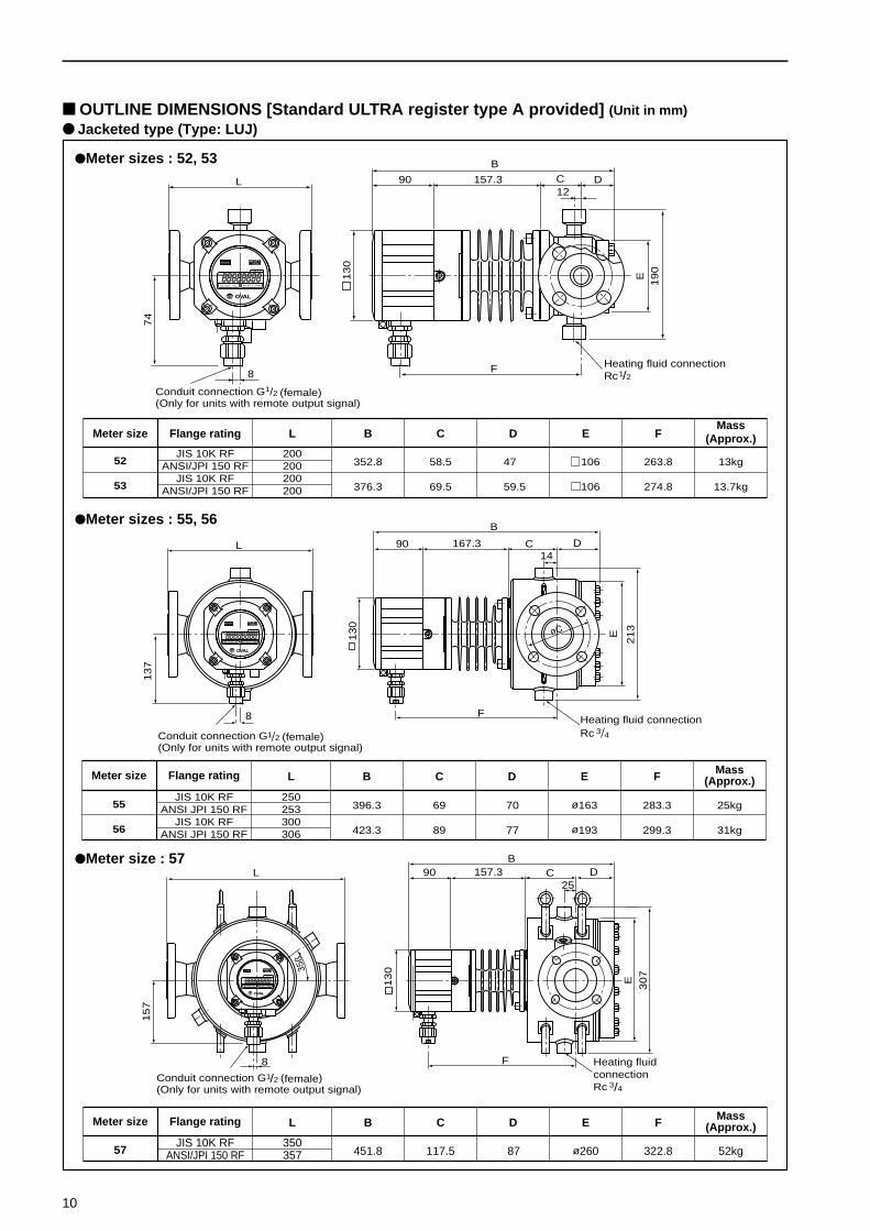
OUTLINE DIMENSIONS [Standard ULTRA register type A provided] (Unit in mm) Jacketed type (Type: LUJ)
10
Meter size Flange rating L B C D E F Mass(Approx.)
JIS 10K RF 250396.3 69 70 ø163 283.3 25kg55 ANSI JPI 150 RF 253
JIS 10K RF 300423.3 89 77 ø193 299.3 31kg56 ANSI JPI 150 RF 306

11
L L
H
H
SR0 3 03C(E)
123
12
345
345SR0 1 031 SR0 8 032
L
H
C(E)
C(E)
Model number Nominal size Flange rating L (mm) H (mm) Body material Screen material std. screen mesh Applicable meters
SR013C031 JIS 10K RF 180
SR013C032ANSI/JPI 150 RF 178 100 39
10mm JIS 20K RF 184 SCS14A SUS316 200 41
SR013C032JIS 30K RF 188 45
ANSI/JPI 300 RF 185126
SR023 C 031 JIS 10K RF 180(E)
SR023 C 032 20mm ANSI/JPI 150 RF 177 100SCS14A SUS316
200 50(E)
SR023 C 032 JIS 20K RF 184(SCS16A) (SUS316L)
(E)
SR031 C 031 JIS 10K RF 230 165(E)
SR038 C 032 25mm ANSI/JPI 150 RF 231SCS14A SUS316
10052
(E)
SR038 C 032 JIS 20K RF 234209 (SCS16A) (SUS316L) 53
(E)
SR041 C 031 JIS 10K RF 230 165(E)
SR048 C 032 40mm ANSI/JPI 150 RF 233SCS14A SUS316
60 55(E)
SR048 C 032 JIS 20K RF 234209 (SCS16A) (SUS316L)
(E)
SR051 C 031 JIS 10K RF 290 190(E)
SR058 C 032 50mm ANSI/JPI 150 RF 296242
SCS14A SCS31660
56(E)
SR058 C 032 JIS 20K RF 294(SCS16A) (SCS316L) 57
(E)
It is essential that a strainer be provided immediatelyupstream of, or as close as to, the flowmeter to preventsolids suspended in the process fluid from entering themeter, possibly leading to costly downtime.
STRAINERS

Sales Representative:
The specification as of July, 2006 is stated in this GS Sheet. Specifications and design are subject to change without notice.
1. Model L_______________________ Standard High temp. Low temp. Jacketed
2. Fluid to be measured Name_________________ Viscosity________mPa·s Specific gravity _________
3. Flowrate (L/h, m3/h) Maximum______________ Normal______________ Minimum______________
4. Fluid temperature (˚C) Maximum______________ Normal______________ Minimum______________
5. Ambient temperature (˚C) Maximum______________ Normal______________ Minimum______________
6. Pressure (MPa) Maximum______________ Normal______________ Minimum______________
7. Flow direction Right Left, Bottom Top
8. Flange connection Nominal size______________mm, Flange rating______________
9. Required Linearity ±______________%
10. Explosionproof construction Required class______________ Not required
11. Accessories Strainer, Air eliminator, Companion flange
12. Quantity Including accessories______________
_____________(dosing, sampling, blending process, etc.)
13. Application Flow integration, Flow indication, Record, Flow control,
Batch control, CPU interface, Others
14. Receiving instrument Type, manufacturer, model, specifications (input, output, power supply, etc.)
15. Distance between flow meter
and receiving instrument ______________m
ORDERING INFORMATIONPlease complete the following form when making inquiries.
OPERATING PRECAUTIONS1. Every OVAL flowmeter is carefully assembled and
precisely adjusted to measure flows down to minuteflows before is leaves the factory. Take everyprecaution in uncrating, installation in the pipingassembly, and testing.
2. Never allow foreign solids to enter the measuringchamber.
3. Flush the piping assembly thoroughly.4. Avoid allowing the meter rotors to spin uncontrolled
by directing a stream of air, etc. or allowing the fluidto flow excessively - even momentarily.
5. It is esseritial that a strainer (supplied by OVAL)exclusively designed for OVAL flowmeters be used.
6. This flowmeter is not provided with subtractfunction. If pulsation in the flow (where the fluidmoves back and forth in the pipeline under theinfluence of pressure) or reversal of flow exists, thetotal counter may show erratic reading, accumulatingall incoming pulses irrespective of flow direction.
REQUIRED SPACE AROUND THE METER
Min
30
0
Min
30
0
Min 500
Min 500
Min
30
0
Min
30
0
Unit in mm