UL924 - Functional Devices, Inc.
24
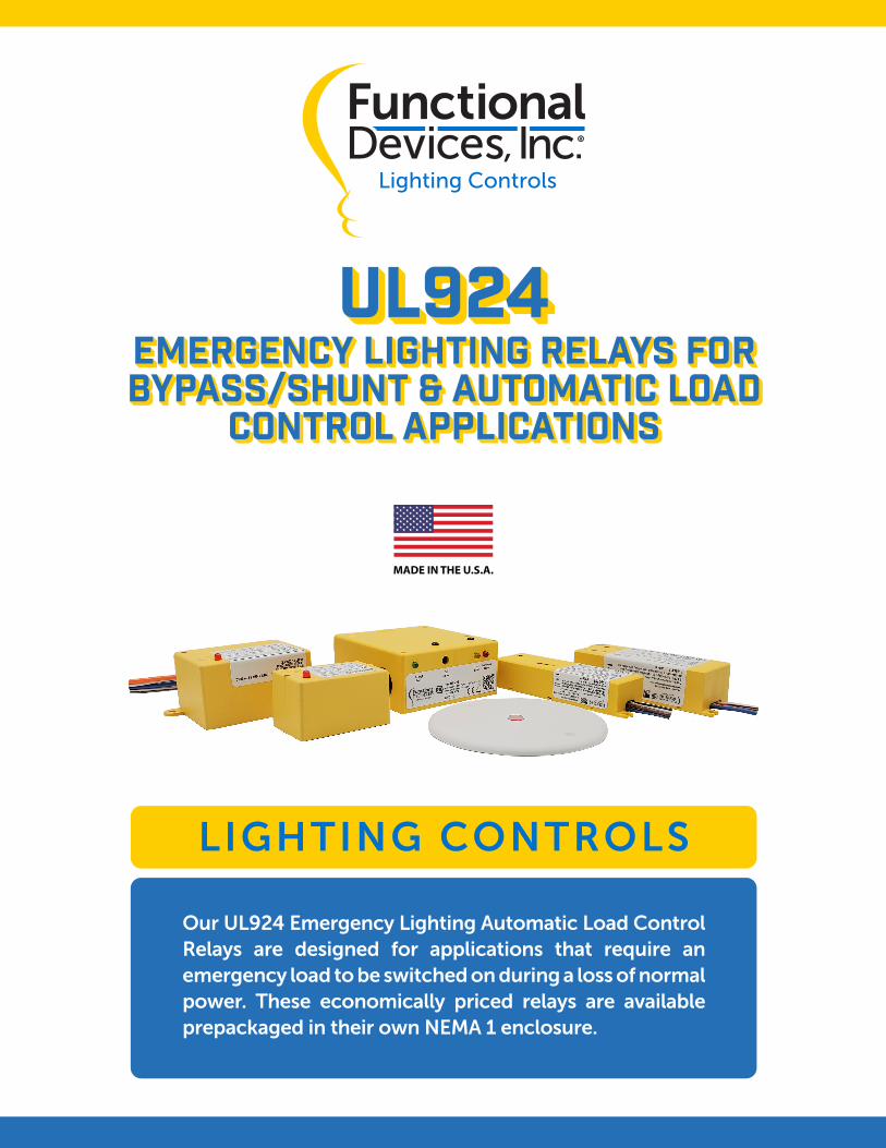
LIGHTING CONTROLS UL924 UL924 EMERGENCY LIGHTING Relays for BYPASS/SHUNT & Automatic load control applications EMERGENCY LIGHTING Relays for BYPASS/SHUNT & Automatic load control applications Our UL924 Emergency Lighting Automatic Load Control Relays are designed for applications that require an emergency load to be switched on during a loss of normal power. These economically priced relays are available prepackaged in their own NEMA 1 enclosure.
Transcript of UL924 - Functional Devices, Inc.
LIGHTING CONTROLS
UL924UL924EMERGENCY LIGHTING Relays for BYPASS/SHUNT & Automatic load
control applications
EMERGENCY LIGHTING Relays for BYPASS/SHUNT & Automatic load
control applications
Our UL924 Emergency Lighting Automatic Load Control Relays are designed for applications that require an emergency load to be switched on during a loss of normal power. These economically priced relays are available prepackaged in their own NEMA 1 enclosure.

www.functionaldevices.com/lighting-controls • (800) 888-5538
Table of Contents
Functional Devices Lighting
UL924 Emergency Lighting Bypass/Shunt Relays 17
UL924 Emergency Lighting Automatic Load Control Relays 3
ESRB 3
ESRN 3
ESRN-1 9
ESRLBC 10
ESRLBCND 12
ESRBE01C 14
ESRBE277C 15
ESRTB 16
ESR2401B 18
ESR2402B 19
ESR2401D 20
ESR2402D 21
ESR01P 22
ESR02P 23
www.functionaldevices.com/lighting-controls • (800) 888-5538 3
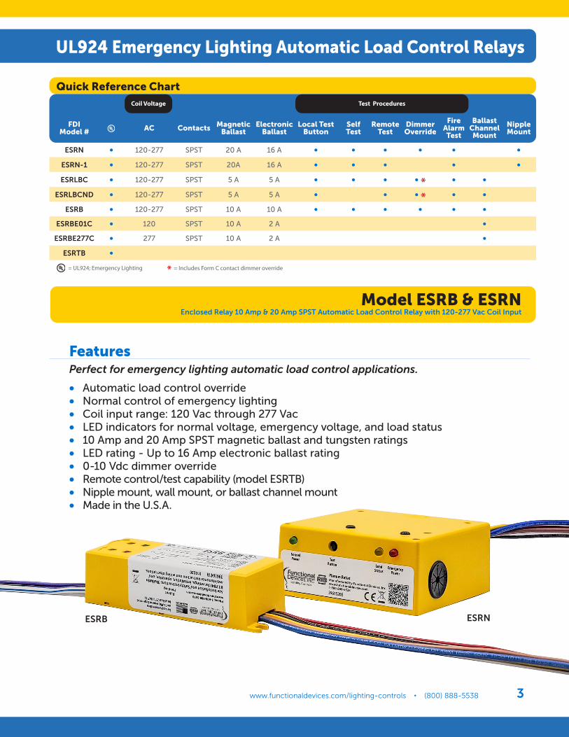
UL924 Emergency Lighting Automatic Load Control Relays
ESRB ESRN
= UL924; Emergency Lighting
FeaturesPerfect for emergency lighting automatic load control applications.
• Automatic load control override• Normal control of emergency lighting• Coil input range: 120 Vac through 277 Vac• LED indicators for normal voltage, emergency voltage, and load status• 10 Amp and 20 Amp SPST magnetic ballast and tungsten ratings• LED rating - Up to 16 Amp electronic ballast rating• 0-10 Vdc dimmer override• Remote control/test capability (model ESRTB)• Nipple mount, wall mount, or ballast channel mount• Made in the U.S.A.
Quick Reference Chart
FDI Model # AC Contacts Magnetic
BallastElectronic
BallastLocal Test
ButtonSelf Test
Remote Test
Dimmer Override
Fire Alarm Test
Ballast Channel Mount
Nipple Mount
ESRN • 120-277 SPST 20 A 16 A • • • • • •ESRN-1 • 120-277 SPST 20A 16 A • • • • •ESRLBC • 120-277 SPST 5 A 5 A • • • • * • •
ESRLBCND • 120-277 SPST 5 A 5 A • • • * • •ESRB • 120-277 SPST 10 A 10 A • • • • • •
ESRBE01C • 120 SPST 10 A 2 A •ESRBE277C • 277 SPST 10 A 2 A •
ESRTB •
Coil Voltage Test Procedures
* = Includes Form C contact dimmer override
Model ESRB & ESRNEnclosed Relay 10 Amp & 20 Amp SPST Automatic Load Control Relay with 120-277 Vac Coil Input
www.functionaldevices.com/lighting-controls • (800) 888-5538Functional Devices, Inc. • Lighting Control Products4
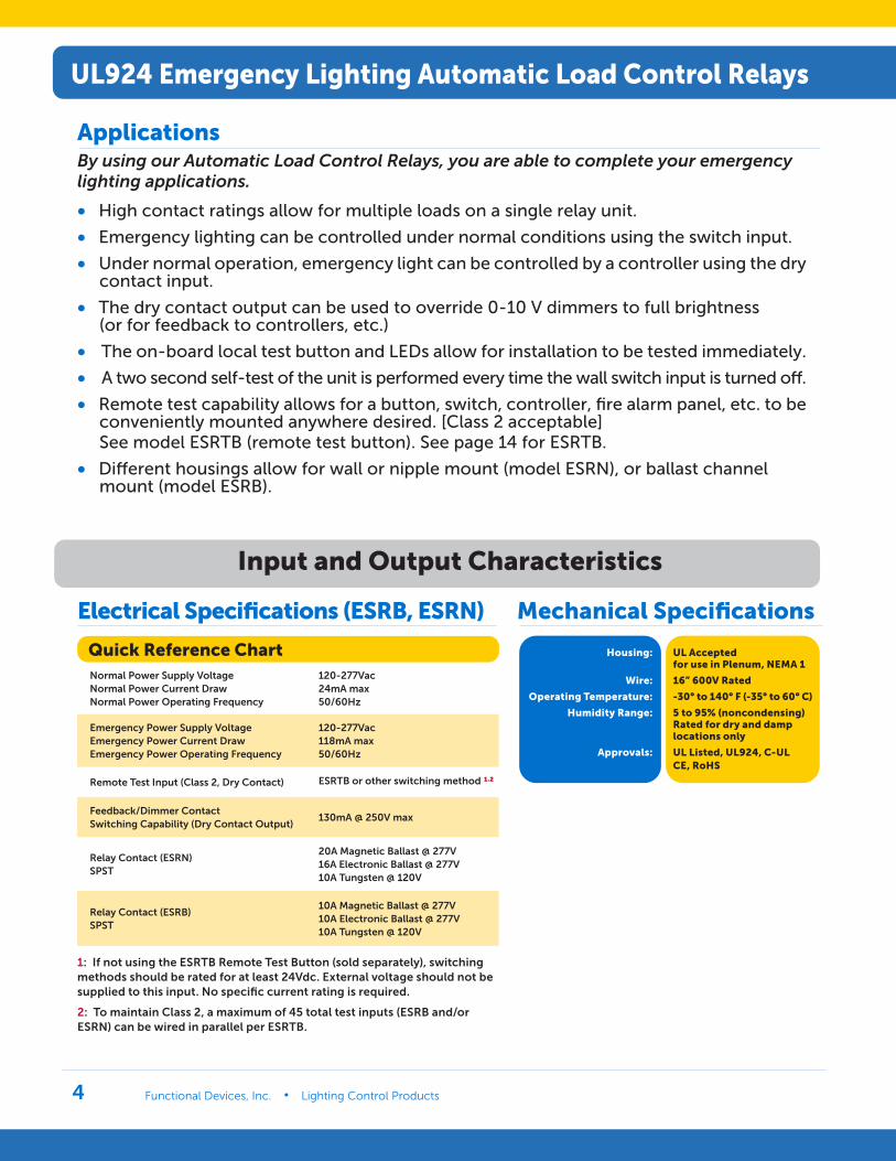
ApplicationsBy using our Automatic Load Control Relays, you are able to complete your emergency lighting applications.
• High contact ratings allow for multiple loads on a single relay unit.
• Emergency lighting can be controlled under normal conditions using the switch input.
• Under normal operation, emergency light can be controlled by a controller using the dry contact input.
• The dry contact output can be used to override 0-10 V dimmers to full brightness (or for feedback to controllers, etc.)
• The on-board local test button and LEDs allow for installation to be tested immediately.
• A two second self-test of the unit is performed every time the wall switch input is turned off.
• Remote test capability allows for a button, switch, controller, fire alarm panel, etc. to be conveniently mounted anywhere desired. [Class 2 acceptable] See model ESRTB (remote test button). See page 14 for ESRTB.
• Different housings allow for wall or nipple mount (model ESRN), or ballast channel mount (model ESRB).
Input and Output Characteristics
Mechanical SpecificationsElectrical Specifications (ESRB, ESRN)
1: If not using the ESRTB Remote Test Button (sold separately), switching methods should be rated for at least 24Vdc. External voltage should not be supplied to this input. No specific current rating is required.
2: To maintain Class 2, a maximum of 45 total test inputs (ESRB and/or ESRN) can be wired in parallel per ESRTB.
Housing:
Wire:
Operating Temperature:
Humidity Range:
Approvals:
UL Accepted for use in Plenum, NEMA 1
16” 600V Rated
-30° to 140° F (-35° to 60° C)
5 to 95% (noncondensing) Rated for dry and damp locations only
UL Listed, UL924, C-ULCE, RoHS
Quick Reference Chart Normal Power Supply Voltage Normal Power Current Draw Normal Power Operating Frequency
120-277Vac 24mA max 50/60Hz
Emergency Power Supply Voltage Emergency Power Current Draw Emergency Power Operating Frequency
120-277Vac 118mA max 50/60Hz
Remote Test Input (Class 2, Dry Contact) ESRTB or other switching method ¹,²
Feedback/Dimmer Contact Switching Capability (Dry Contact Output)
130mA @ 250V max
Relay Contact (ESRN) SPST
20A Magnetic Ballast @ 277V 16A Electronic Ballast @ 277V 10A Tungsten @ 120V
Relay Contact (ESRB) SPST
10A Magnetic Ballast @ 277V 10A Electronic Ballast @ 277V 10A Tungsten @ 120V
UL924 Emergency Lighting Automatic Load Control Relays
www.functionaldevices.com/lighting-controls • (800) 888-5538 5
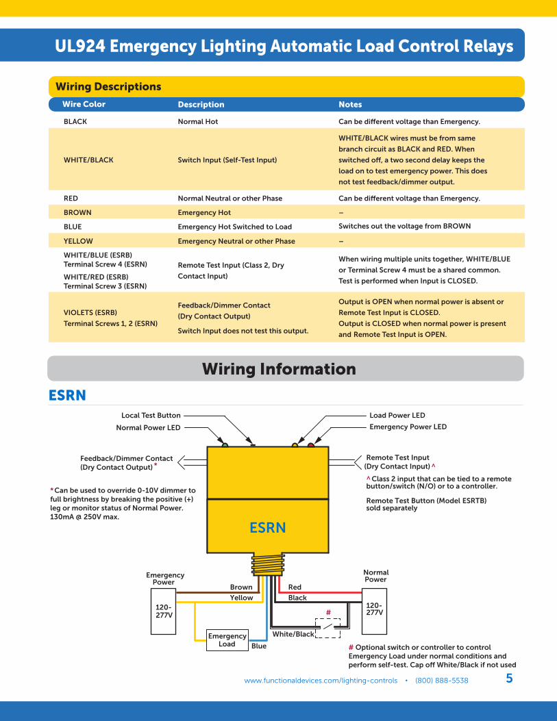
Wiring Descriptions
Wire Color Description Notes
BLACK Normal Hot Can be different voltage than Emergency.
WHITE/BLACK Switch Input (Self-Test Input)
WHITE/BLACK wires must be from same
branch circuit as BLACK and RED. When
switched off, a two second delay keeps the
load on to test emergency power. This does
not test feedback/dimmer output.
RED Normal Neutral or other Phase Can be different voltage than Emergency.
BROWN Emergency Hot –
BLUE Emergency Hot Switched to Load Switches out the voltage from BROWN
YELLOW Emergency Neutral or other Phase –
WHITE/BLUE (ESRB) Terminal Screw 4 (ESRN)
WHITE/RED (ESRB) Terminal Screw 3 (ESRN)
Remote Test Input (Class 2, Dry
Contact Input)
When wiring multiple units together, WHITE/BLUE
or Terminal Screw 4 must be a shared common.
Test is performed when Input is CLOSED.
VIOLETS (ESRB)
Terminal Screws 1, 2 (ESRN)
Feedback/Dimmer Contact
(Dry Contact Output)
Switch Input does not test this output.
Output is OPEN when normal power is absent or
Remote Test Input is CLOSED.
Output is CLOSED when normal power is present
and Remote Test Input is OPEN.
ESRN
Brown
Yellow
Red
Black
EmergencyLoad
120-277V
Blue
EmergencyPower
White/Black
Power
120-277V
# Optional switch or controller to control Emergency Load under normal conditions andperform self-test. Cap o� White/Black if not used
#
Remote Test Input(Dry Contact Input) ^ ^ Class 2 input that can be tied to a remote button/switch (N/O) or to a controller.
Remote Test Button (Model ESRTB) sold separately
Feedback/Dimmer Contact(Dry Contact Output) *
* Can be used to override 0-10V dimmer to full brightness by breaking the positive (+) leg or monitor status of Normal Power.130mA @ 250V max.
Local Test Button
Normal Power LED
Load Power LED
Emergency Power LED
1 2 3 4
Normal
ESRN
Wiring Information
UL924 Emergency Lighting Automatic Load Control Relays
www.functionaldevices.com/lighting-controls • (800) 888-5538Functional Devices, Inc. • Lighting Control Products6
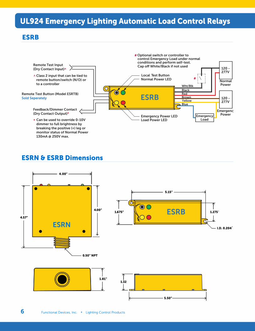
ESRB
ESRN & ESRB Dimensions
ESRN
4.00”
4.00”
4.57”
0.50” NPT
1.81”
5.50”
5.15”
1.675” 1.275
1.32
ESRB
I.D. 0.204
”
”
Blue
RedBlackWht/Blk
YellowBrown
Load Power LEDEmergency Power LED
NormalPower
120 -277V
EmergencyPower
ESRB
# Optional switch or controller tocontrol Emergency Load under normal conditions and perform self-test.
Local Test ButtonNormal Power LED
*
^ #
Cap o� White/Black if not usedRemote Test Input(Dry Contact Input)^
Class 2 input that can be tied to remote button/switch (N/O) orto a controller
Remote Test Button (Model ESRTB)Sold Seperately
Feedback/Dimmer Contact (Dry Contact Output)*
Can be used to override 0-10Vdimmer to full brightness by breaking the positive (+) leg or monitor status of Normal Power130mA @ 250V max.
120 -277V
EmergencyLoad
UL924 Emergency Lighting Automatic Load Control Relays
www.functionaldevices.com/lighting-controls • (800) 888-5538 7
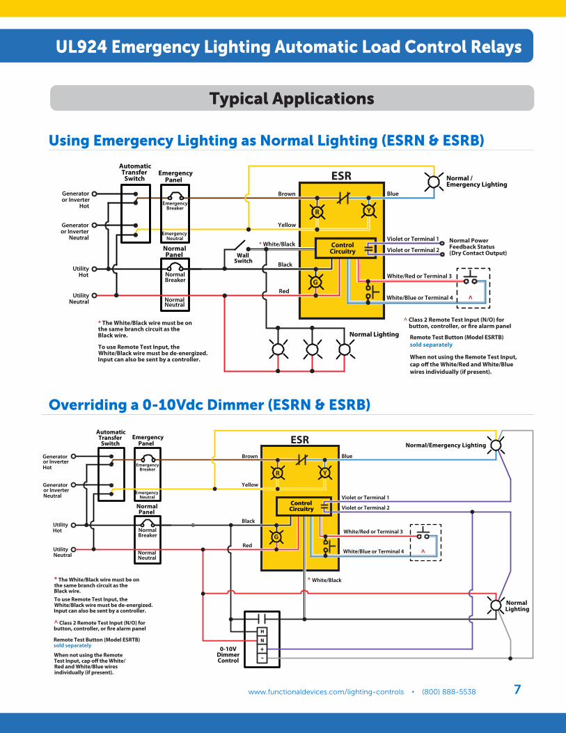
Using Emergency Lighting as Normal Lighting (ESRN & ESRB)
Overriding a 0-10Vdc Dimmer (ESRN & ESRB)
R Y
Normal PowerFeedback Status(Dry Contact Output)
Normal /Emergency Lighting
WallSwitch
AutomaticTransfer
Switch
UtilityHot
UtilityNeutral
NormalPanel
EmergencyBreaker
EmergencyNeutral
EmergencyPanel
NormalBreaker
ESR
NormalNeutral
Generatoror Inverter
Hot
Generatoror Inverter
Neutral
Brown
Yellow
* White/Black
Black
Red
Blue
Violet or Terminal 1
White/Red or Terminal 3
White/Blue or Terminal 4
Normal Lighting
^ Class 2 Remote Test Input (N/O) for button, controller, or �re alarm panel* The White/Black wire must be on
the same branch circuit as theBlack wire.
To use Remote Test Input, theWhite/Black wire must be de-energized.Input can also be sent by a controller.
^
Remote Test Button (Model ESRTB) sold separately
When not using the Remote Test Input, cap o� the White/Red and White/Blue wires individually (if present).
Violet or Terminal 2Control
Circuitry
G
R Y
Normal/Emergency Lighting
AutomaticTransfer
Switch
UtilityHot
UtilityNeutral
NormalPanel
EmergencyBreaker
EmergencyNeutral
EmergencyPanel
NormalBreaker
ESR
NormalNeutral
Generatoror InverterHot
Generatoror InverterNeutral
Brown
Yellow
Black
Red
Blue
Violet or Terminal 1
White/Red or Terminal 3
White/Blue or Terminal 4 ^
G
Violet or Terminal 2Control
Circuitry
* The White/Black wire must be onthe same branch circuit as theBlack wire.
When not using the RemoteTest Input, cap o� the White/Red and White/Blue wiresindividually (if present).
To use Remote Test Input, theWhite/Black wire must be de-energized.Input can also be sent by a controller.
^ Class 2 Remote Test Input (N/O) forbutton, controller, or �re alarm panel
Remote Test Button (Model ESRTB) sold separately
H
N
+-
0-10VDimmerControl
* White/Black
Normal Lighting
Typical Applications
UL924 Emergency Lighting Automatic Load Control Relays
www.functionaldevices.com/lighting-controls • (800) 888-5538Functional Devices, Inc. • Lighting Control Products8
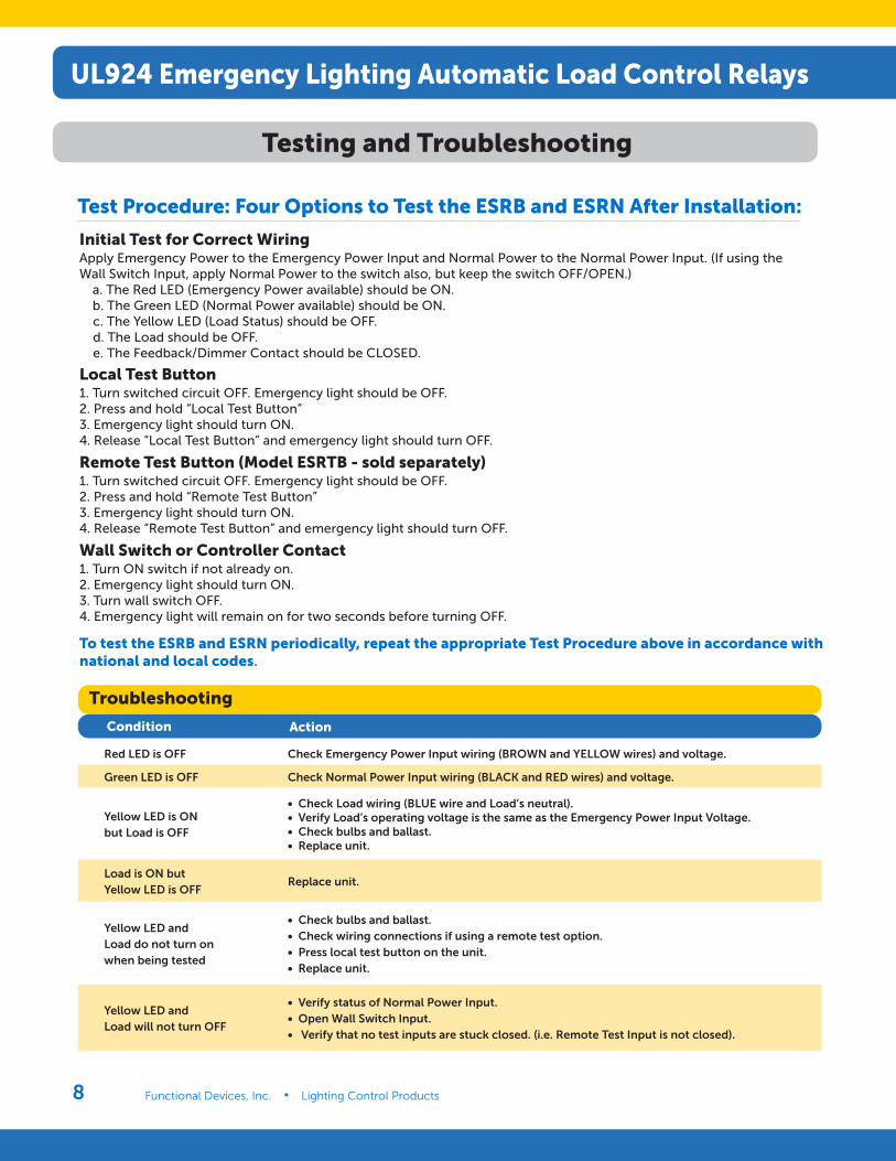
Test Procedure: Four Options to Test the ESRB and ESRN After Installation:
Initial Test for Correct WiringApply Emergency Power to the Emergency Power Input and Normal Power to the Normal Power Input. (If using the Wall Switch Input, apply Normal Power to the switch also, but keep the switch OFF/OPEN.) a. The Red LED (Emergency Power available) should be ON. b. The Green LED (Normal Power available) should be ON. c. The Yellow LED (Load Status) should be OFF. d. The Load should be OFF. e. The Feedback/Dimmer Contact should be CLOSED.
To test the ESRB and ESRN periodically, repeat the appropriate Test Procedure above in accordance with national and local codes.
Local Test Button1. Turn switched circuit OFF. Emergency light should be OFF.2. Press and hold “Local Test Button”3. Emergency light should turn ON.4. Release “Local Test Button” and emergency light should turn OFF.
Remote Test Button (Model ESRTB - sold separately)1. Turn switched circuit OFF. Emergency light should be OFF.2. Press and hold “Remote Test Button”3. Emergency light should turn ON.4. Release “Remote Test Button” and emergency light should turn OFF.
Wall Switch or Controller Contact1. Turn ON switch if not already on.2. Emergency light should turn ON.3. Turn wall switch OFF.4. Emergency light will remain on for two seconds before turning OFF.
Troubleshooting
Condition Action
Red LED is OFF Check Emergency Power Input wiring (BROWN and YELLOW wires) and voltage.
Green LED is OFF Check Normal Power Input wiring (BLACK and RED wires) and voltage.
Yellow LED is ON but Load is OFF
• Check Load wiring (BLUE wire and Load’s neutral). • Verify Load’s operating voltage is the same as the Emergency Power Input Voltage. • Check bulbs and ballast. • Replace unit.
Load is ON but Yellow LED is OFF
Replace unit.
Yellow LED and Load do not turn on when being tested
• Check bulbs and ballast. • Check wiring connections if using a remote test option. • Press local test button on the unit. • Replace unit.
Yellow LED and Load will not turn OFF
• Verify status of Normal Power Input. • Open Wall Switch Input. • Verify that no test inputs are stuck closed. (i.e. Remote Test Input is not closed).
Testing and Troubleshooting
UL924 Emergency Lighting Automatic Load Control Relays
www.functionaldevices.com/lighting-controls • (800) 888-5538 9
UL924 Emergency Lighting Automatic Load Control Relays
# Relays & Contact Type:Expected Relay Life:
Operating Temperature:Operate Time:
LED:
Dimensions:Wires:
Approvals:Housing Rating:
Gold Flash:Override (Test Switch):
Humidity Range:
One (1) SPST Continuous Duty Coil10 million cycles minimum mechanical-30 to 140° F18msGreen = Normal PowerRed = Emergency PowerYellow = Load Power4.0˝ x 4.57˝ x 1.80˝ with .50˝ NPT Nipple16˝, 600V RatedUL Listed, UL924, C-UL, CE, RoHS UL Accepted for Use in Plenum, NEMA 1NoNo5-95%(noncondensing)
Coil Current: Normal Power =24 mA maxEmergency Power = 118 mA max
Coil Voltage Input: Emergency Input: 120-277 Vac(50/60 Hz)Normal Input: 120-277 Vac(50/60 Hz)
Specifications
Contact Ratings: 20 Amp Magnetic Ballast @ 277 Vac16 Amp Electronic Ballast @ 277 Vac10 Amp Tungsten @ 120 Vac
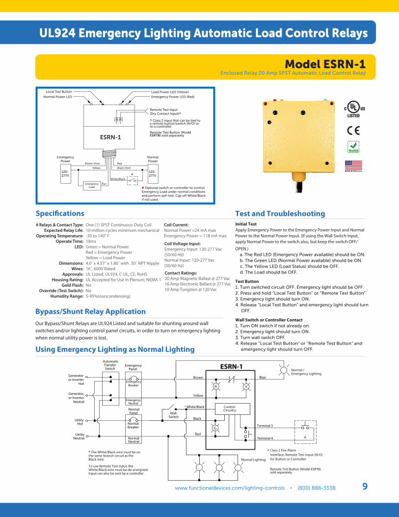
Test and TroubleshootingInitial TestApply Emergency Power to the Emergency Power Input and Normal Power to the Normal Power Input. (If using the Wall Switch Input, apply Normal Power to the switch also, but keep the switch OFF/
OPEN.) a. The Red LED (Emergency Power available) should be ON. b. The Green LED (Normal Power available) should be ON. c. The Yellow LED (Load Status) should be OFF. d. The Load should be OFF.
Test Button1. Turn switched circuit OFF. Emergency light should be OFF.2. Press and hold “Local Test Button” or “Remote Test Button”3. Emergency light should turn ON.4. Release “Local Test Button” and emergency light should turn OFF.
Wall Switch or Controller Contact1. Turn ON switch if not already on.2. Emergency light should turn ON.3. Turn wall switch OFF.4. Release “Local Test Button” or “Remote Test Button” and emergency light should turn OFF.
Bypass/Shunt Relay ApplicationOur Bypass/Shunt Relays are UL924 Listed and suitable for shunting around wall switches and/or lighting control panel circuits, in order to turn on emergency lighting when normal utility power is lost.
#
Remote Test Input(Dry Contact Input)^ ^ Class 2 input that can be tied to a remote button/switch (N/O) or to a controller.
Remote Test Button (Model ESRTB) sold separately
Local Test Button
Normal Power LED
Load Power LED (Yellow)
Emergency Power LED (Red)
ESRN-1
3 4
EmergencyLoad # Optional switch or controller to control
Emergency Load under normal conditions and perform self-test. Cap off White/Black if not used.
120-277V
Blue
EmergencyPower
Brown (Hot)
Yellow
Red
Black (Hot)
White/Black
NormalPower
120-277V
Using Emergency Lighting as Normal Lighting
G
ControlCircuitry
R Y
Normal /Emergency Lighting
WallSwitch
AutomaticTransferSwitch
UtilityHot
UtilityNeutral
NormalPanel
EmergencyBreaker
EmergencyNeutral
EmergencyPanel
NormalBreaker
ESRN-1
NormalNeutral
Generatoror Inverter
Hot
Generatoror Inverter
Neutral
Brown
Yellow
* White/Black
Black
Red
Blue
Terminal 3
Terminal 4
Normal Lighting
^ Class 2 Fire Alarm Interface, Remote Test Input (N/O) for Button or Controller
* The White/Black wire must be onthe same branch circuit as theBlack wire.
To use Remote Test Input, theWhite/Black wire must be de-energized.Input can also be sent by a controller.
^
Remote Test Button (Model ESRTB) sold separately
Model ESRN-1Enclosed Relay 20 Amp SPST Automatic Load Control Relay
www.functionaldevices.com/lighting-controls • (800) 888-5538Functional Devices, Inc. • Lighting Control Products10
# Relays & Contact Type:Expected Relay Life:
Operating Temperature:Operate Time:
LED:
Dimensions:Wires:
Approvals:Housing Rating:
Gold Flash:Override (Test Switch):
Humidity Range:
One (1) SPST Continuous Duty Coil10 million cycles minimum mechanical-30 to 140° F18msGreen = Normal PowerRed = Emergency PowerYellow = Load Power5.63˝ x 1.40˝ x 1.00˝ 16˝, 600V RatedUL Listed, UL924, C-UL, CE, RoHS UL Accepted for Use in Plenum, NEMA 1NoNo5-95%(noncondensing)
Coil Current: Normal Power =24 mA maxEmergency Power = 88 mA max
Coil Voltage Input: Emergency Input: 120-277 Vac(50/60 Hz)Normal Input: 120-277 Vac(50/60 Hz)
Specifications
Relay Contact Ratings: 5 Amp Electronic/LED Ballast @ 277 Vac5 Amp Ballast @ 120-277 VacFeedback/Dimmer Override Contact: 1Amp Resistive @ 30 Vdc
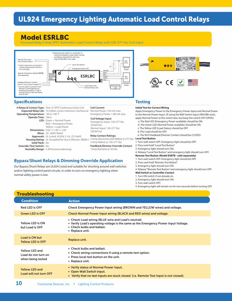
TestingInitial Test for Correct WiringApply Emergency Power to the Emergency Power Input and Normal Power to the Normal Power Input. (If using the Wall Switch Input [Wht/Blk wire], apply Normal Power to the switch also, but keep the switch OFF/OPEN.) a. The Red LED (Emergency Power available) should be ON. b. The Green LED (Normal Power available) should be ON. c. The Yellow LED (Load Status) should be OFF. d. The Load should be OFF. e. The N/O Feedback/Dimmer Contact should be CLOSED.Local Test Button1. Turn wall switch OFF. Emergency light should be OFF.2. Press and hold “Local Test Button”3. Emergency light should turn ON.4. Release “Local Test Button” and emergency light should turn OFF.Remote Test Button (Model ESRTB - sold separately)1. Turn wall switch OFF. Emergency light should be OFF.2. Press and hold “Remote Test Button”3. Emergency light should turn ON.4. Release “Remote Test Button” and emergency light should turn OFF.Wall Switch or Controller Contact1. Turn ON switch if not already on.2. Emergency light should turn ON.3. Turn wall switch OFF.4. Emergency light will remain on for two seconds before turning OFF.
Bypass/Shunt Relays & Dimming Override ApplicationOur Bypass/Shunt Relays are UL924 Listed and suitable for shunting around wall switches and/or lighting control panel circuits, in order to turn on emergency lighting when normal utility power is lost.
Normal Power LEDLoad Power LED
NormalPower
120 -277V
120 -277V
EmergencyPower
ESRLBC
EmergencyLoad
Blue
#
Local Test Button
Emergency Power LED
Feedback/Dimmer Contact
*
* Can be used to override 0-10V dimmer to full brightness by breaking the positive (+) leg or monitor status of Normal Power.1A @ 30 Vdc.
YellowBrownRedBlack
Wht/Blk
Remote Test Input(Dry Contact Input) ^
^ Class 2 input that can be tied to remote button/switch (N/O) orto a controller.
Remote Test Button (Model ESRTB)sold separately
#
(Form C Dry Contact Output)
VioletWht/VioletWht/BlueWht/Red
Wht/Brown
Optional wall switch or controller tocontrol Emergency Load under normalconditions and perform self-test. Cap o� Wht/Blk if not used.
Troubleshooting
Condition Action
Red LED is OFF Check Emergency Power Input wiring (BROWN and YELLOW wires) and voltage.
Green LED is OFF Check Normal Power Input wiring (BLACK and RED wires) and voltage.
Yellow LED is ON but Load is OFF
• Check Load wiring (BLUE wire and Load’s neutral). • Verify Load’s operating voltage is the same as the Emergency Power Input Voltage. • Check bulbs and ballast. • Replace unit.
Load is ON but Yellow LED is OFF
Replace unit.
Yellow LED and Load do not turn on when being tested
• Check bulbs and ballast. • Check wiring connections if using a remote test option. • Press local test button on the unit. • Replace unit.
Yellow LED and Load will not turn OFF
• Verify status of Normal Power Input. • Open Wall Switch Input. • Verify that no test inputs are stuck closed. (i.e. Remote Test Input is not closed).
Model ESRLBCEnclosed Relay 5 Amp SPST Automatic Load Control Relay with 120-277 Vac Coil Input
UL924 Emergency Lighting Automatic Load Control Relays
www.functionaldevices.com/lighting-controls • (800) 888-5538 11
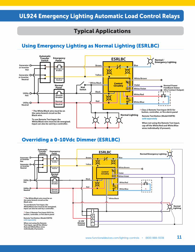
R Y
Normal PowerFeedback Status(Dry Contact Output)
Normal /Emergency Lighting
WallSwitch
AutomaticTransfer
Switch
UtilityHot
UtilityNeutral
NormalPanel
EmergencyBreaker
EmergencyNeutral
EmergencyPanel ESRLBC
NormalNeutral
Generatoror Inverter
Hot
Generatoror Inverter
Neutral
Brown
Yellow
* White/Black
Black
Red
Blue
Violet
White/Red
White/Blue
Normal Lighting
^ Class 2 Remote Test Input (N/O) for button, controller, or �re alarm panel* The White/Black wire must be on
the same branch circuit as theBlack wire.
To use Remote Test Input, theWhite/Black wire must be de-energized.Input can also be sent by a controller.
^
Remote Test Button (Model ESRTB) sold separately
When not using the Remote Test Input, cap o� the White/Red and White/Blue wires individually (if present).
G
White/Violet
ControlCircuitry
White/Brown
NormalBreaker
R
Normal/Emergency Lighting
AutomaticTransfer
Switch
UtilityHot
UtilityNeutral
NormalPanel
EmergencyBreaker
EmergencyNeutral
EmergencyPanel
NormalBreaker
ESRLBC
NormalNeutral
Generatoror InverterHot
Generatoror InverterNeutral
Brown
Yellow
Black
Red
Blue
White/Red
White/Blue ^
G
* The White/Black wire must be onthe same branch circuit as theBlack wire.
When not using the RemoteTest Input, cap o� the White/Red and White/Blue wiresindividually (if present).
To use Remote Test Input, theWhite/Black wire must be de-energized.Input can also be sent by a controller.
^ Class 2 Remote Test Input (N/O) forbutton, controller, or �re alarm panel
Remote Test Button (Model ESRTB) sold separately
H
N
+-
0-10VDimmerControl
* White/Black
Violet
White/Violet
ControlCircuitry
White/Brown
Y
NormalLighting
Using Emergency Lighting as Normal Lighting (ESRLBC)
Overriding a 0-10Vdc Dimmer (ESRLBC)
Typical Applications
UL924 Emergency Lighting Automatic Load Control Relays
www.functionaldevices.com/lighting-controls • (800) 888-5538Functional Devices, Inc. • Lighting Control Products12
# Relays & Contact Type:Expected Relay Life:
Operating Temperature:Operate Time:
LED:
Dimensions:Wires:
Approvals:Housing Rating:
Gold Flash:Override (Test Switch):
Humidity Range:
One (1) SPST Continuous Duty Coil10 million cycles minimum mechanical-30 to 140° F18msGreen = Normal PowerRed = Emergency PowerYellow = Load Power5.63˝ x 1.40˝ x 1.00˝ 16˝, 600V RatedUL Listed, UL924, C-UL, CE, RoHS UL Accepted for Use in Plenum, NEMA 1NoNo5-95%(noncondensing)
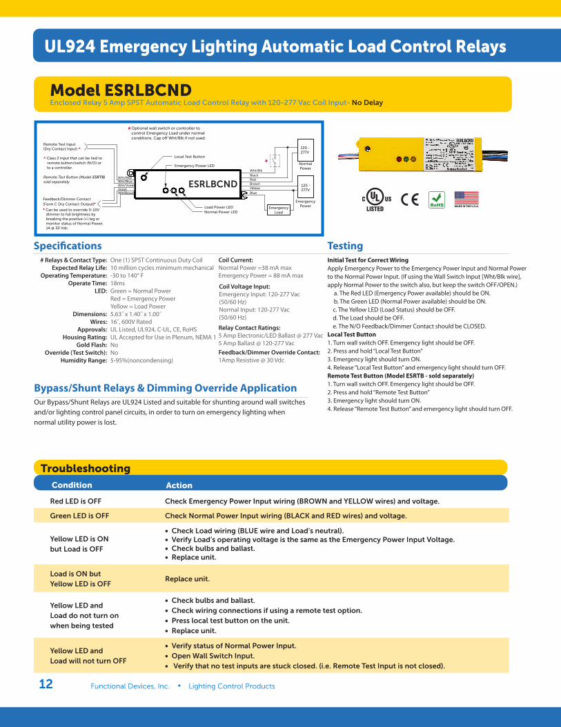
Coil Current: Normal Power =38 mA maxEmergency Power = 88 mA max
Coil Voltage Input: Emergency Input: 120-277 Vac(50/60 Hz)Normal Input: 120-277 Vac(50/60 Hz)
Specifications
Relay Contact Ratings: 5 Amp Electronic/LED Ballast @ 277 Vac5 Amp Ballast @ 120-277 VacFeedback/Dimmer Override Contact: 1Amp Resistive @ 30 Vdc
TestingInitial Test for Correct WiringApply Emergency Power to the Emergency Power Input and Normal Power to the Normal Power Input. (If using the Wall Switch Input [Wht/Blk wire], apply Normal Power to the switch also, but keep the switch OFF/OPEN.) a. The Red LED (Emergency Power available) should be ON. b. The Green LED (Normal Power available) should be ON. c. The Yellow LED (Load Status) should be OFF. d. The Load should be OFF. e. The N/O Feedback/Dimmer Contact should be CLOSED.Local Test Button1. Turn wall switch OFF. Emergency light should be OFF.2. Press and hold “Local Test Button”3. Emergency light should turn ON.4. Release “Local Test Button” and emergency light should turn OFF.Remote Test Button (Model ESRTB - sold separately)1. Turn wall switch OFF. Emergency light should be OFF.2. Press and hold “Remote Test Button”3. Emergency light should turn ON.4. Release “Remote Test Button” and emergency light should turn OFF.
Bypass/Shunt Relays & Dimming Override ApplicationOur Bypass/Shunt Relays are UL924 Listed and suitable for shunting around wall switches and/or lighting control panel circuits, in order to turn on emergency lighting when normal utility power is lost.
Troubleshooting
Condition Action
Red LED is OFF Check Emergency Power Input wiring (BROWN and YELLOW wires) and voltage.
Green LED is OFF Check Normal Power Input wiring (BLACK and RED wires) and voltage.
Yellow LED is ON but Load is OFF
• Check Load wiring (BLUE wire and Load’s neutral). • Verify Load’s operating voltage is the same as the Emergency Power Input Voltage. • Check bulbs and ballast. • Replace unit.
Load is ON but Yellow LED is OFF
Replace unit.
Yellow LED and Load do not turn on when being tested
• Check bulbs and ballast. • Check wiring connections if using a remote test option. • Press local test button on the unit. • Replace unit.
Yellow LED and Load will not turn OFF
• Verify status of Normal Power Input. • Open Wall Switch Input. • Verify that no test inputs are stuck closed. (i.e. Remote Test Input is not closed).
Model ESRLBCNDEnclosed Relay 5 Amp SPST Automatic Load Control Relay with 120-277 Vac Coil Input- No Delay
UL924 Emergency Lighting Automatic Load Control Relays
ESRLBCND
# Optional wall switch or controller tocontrol Emergency Load under normalconditions. Cap o� Wht/Blk if not used.
Normal Power LEDLoad Power LED
NormalPower
120 -277V
120 -277V
EmergencyPowerEmergency
Load
Blue
Local Test Button
Emergency Power LED
Feedback/Dimmer Contact *
* Can be used to override 0-10V dimmer to full brightness by breaking the positive (+) leg or monitor status of Normal Power.1A @ 30 Vdc.
YellowBrownRedBlack
Wht/Blk
Remote Test Input(Dry Contact Input) ^
^ Class 2 input that can be tied to remote button/switch (N/O) orto a controller.
Remote Test Button (Model ESRTB)sold separately
#
(Form C Dry Contact Output)
VioletWht/VioletWht/BlueWht/Red
Wht/Brown
www.functionaldevices.com/lighting-controls • (800) 888-5538 13
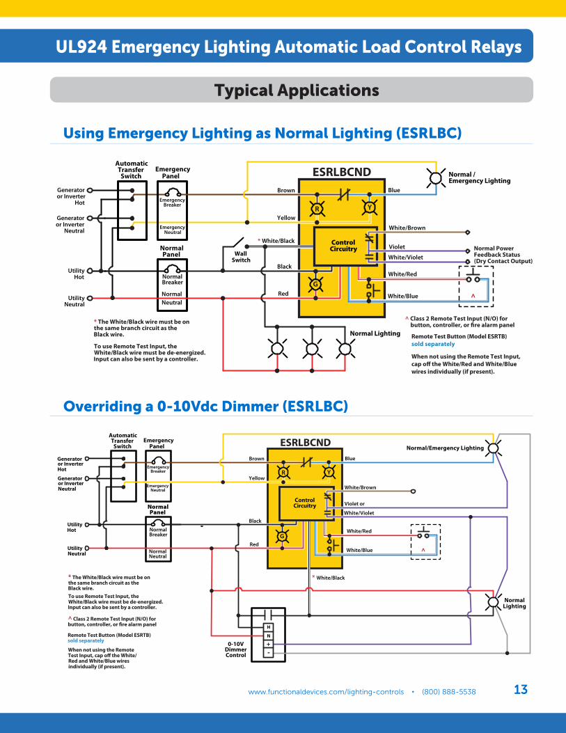
Using Emergency Lighting as Normal Lighting (ESRLBC)
Overriding a 0-10Vdc Dimmer (ESRLBC)
Typical Applications
UL924 Emergency Lighting Automatic Load Control Relays
R Y
Normal PowerFeedback Status(Dry Contact Output)
Normal /Emergency Lighting
WallSwitch
AutomaticTransfer
Switch
UtilityHot
UtilityNeutral
NormalPanel
EmergencyBreaker
EmergencyNeutral
EmergencyPanel ESRLBCND
NormalNeutral
Generatoror Inverter
Hot
Generatoror Inverter
Neutral
Brown
Yellow
* White/Black
Black
Red
Blue
Violet
White/Red
White/Blue
Normal Lighting
^ Class 2 Remote Test Input (N/O) for button, controller, or �re alarm panel* The White/Black wire must be on
the same branch circuit as theBlack wire.
To use Remote Test Input, theWhite/Black wire must be de-energized.Input can also be sent by a controller.
^
Remote Test Button (Model ESRTB) sold separately
When not using the Remote Test Input, cap o� the White/Red and White/Blue wires individually (if present).
G
White/Violet
ControlCircuitry
White/Brown
NormalBreaker
R
Normal/Emergency Lighting
AutomaticTransfer
Switch
UtilityHot
UtilityNeutral
NormalPanel
EmergencyBreaker
EmergencyNeutral
EmergencyPanel
NormalBreaker
NormalNeutral
Generatoror InverterHot
Generatoror InverterNeutral
Brown
Yellow
Black
Red
Blue
White/Red
White/Blue ^
G
* The White/Black wire must be onthe same branch circuit as theBlack wire.
When not using the RemoteTest Input, cap o� the White/Red and White/Blue wiresindividually (if present).
To use Remote Test Input, theWhite/Black wire must be de-energized.Input can also be sent by a controller.
^ Class 2 Remote Test Input (N/O) forbutton, controller, or �re alarm panel
Remote Test Button (Model ESRTB) sold separately
H
N
+-
0-10VDimmerControl
* White/Black
Violet or
White/Violet
ControlCircuitry
White/Brown
Y
NormalLighting
ESRLBCND

www.functionaldevices.com/lighting-controls • (800) 888-5538Functional Devices, Inc. • Lighting Control Products14
BlkUtility 120 Vac
PrpSwitched Utility
120 Vac
WhtUtility Neutral
BluEmergency Hot
to Load
YelEmergency Hot
GryEmergency Neutral
Specifications
Initial Wiring Verification 1. Turn OFF Normal Power, Transfer Power, and Wall Switch.
2. Wire relay according to wiring diagram.
3. Energize Transfer Power. Emergency Light should illuminate.
4. Energize Normal Power. Emergency Light will turn OFF.
5. Turn ON Wall Switch. Emergency Light should illuminate.
Field Inspection 1. Ensure Normal Power and Transfer Power are energized.
2. Turn OFF Wall Switch. Light will turn OFF.
3. Red LED and Yellow LED will be illuminated.
4. Turn OFF Normal Power. Red LED will turn OFF. Emergency Light will illuminate.
Use of Normal Light as Emergency LightOur Emergency Bypass / Shunt Relays are UL924 Listed and suitable for shunting around wall switches in order to turn on emergency lighting in the event of loss of normal utility power.
When the Emergency Light is needed as a Normal Light as well, this application can be applied using this specific relay.
When Normal Power is present, the ESR relay coil is activated and the emergency panel is fed from Normal Power. The lighting load can be switched on/off using the existing wall switch.
When Normal Power drops out, the ESR coil is deactivated and N/C contact falls closed. The Automatic Transfer Switch changes over to backup (generator) power, and the Emergency Light remains illuminated, regardless of the position of the existing wall switch, while the Normal Lighting is off.
BlkUtility 120 Vac
PrpSwitched Utility
120 Vac
WhtUtility Neutral
BluEmergency Hot
to Load
YelEmergency Hot
GryEmergency Neutral
Normal Lighting
Normal /Emergency Lighting
WallSwitch
AutomaticTransferSwitch
Generatoror Inverter
Hot
Generatoror Inverter
Neutral
UtilityHot
UtilityNeutral Normal
Neutral
NormalPanel
EmergencyBreaker
EmergencyNeutral
EmergencyPanel
NormalBreaker
ESR
ControlCircuitry
Yellow
Gray
Purple
Black
White
Blue
# Relays & Contact Type:Expected Relay Life:
Operating Temperature:Operate Time:
Relay Status:Emergency Power Present:
Dimensions:Wires:
Approvals:Gold Flash:
One (1) SPST-NC Continuous Duty Coil10 million cycles minimum mechanical-30 to 140° F50 msRed LED On = ActivatedYellow LED On = Transfer Power Present4.60˝ x 1.20˝ x 1.70˝ 16.00˝, 600V RatedUL Listed, UL924, C-UL, CE, RoHS No
Contact Ratings: 10 Amp Magnetic Ballast @ 277 Vac (N/C)2 Amp Electronic Ballast @ 120 Vac (N/C)
Coil Current: 100 mA @ 120 Vac
Coil Voltage Input: 120 Vac ; 50-60 Hz
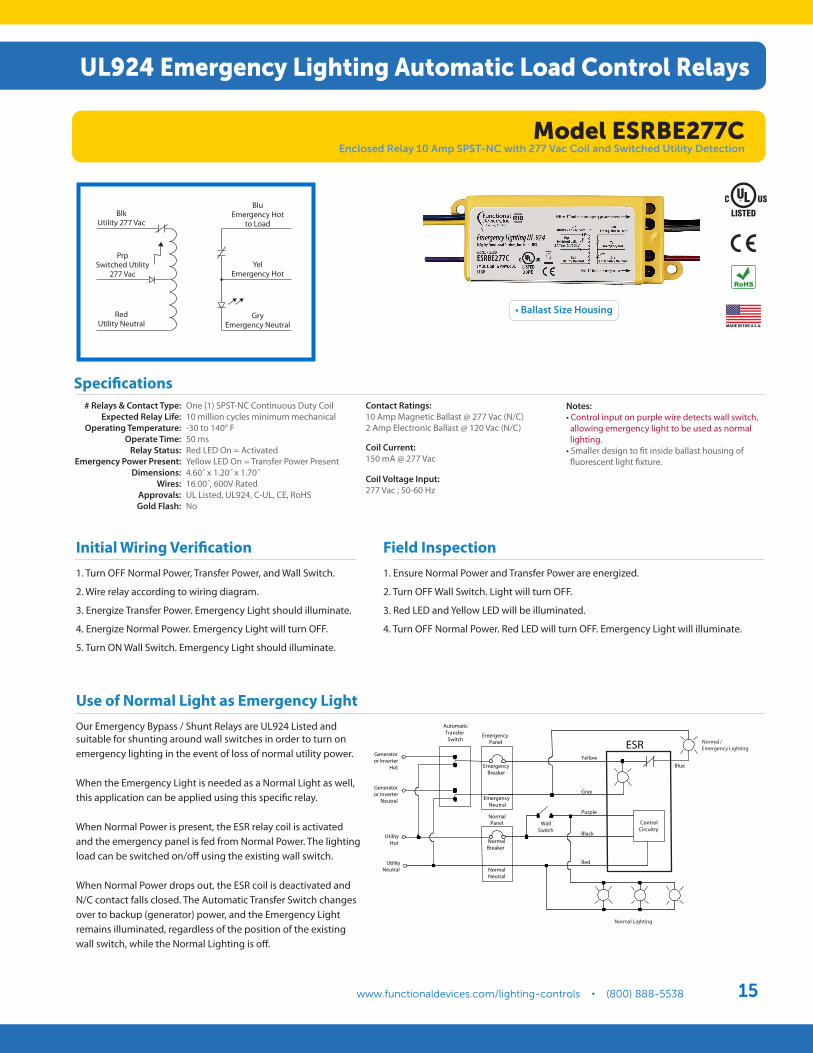
Notes: • Control input on purple wire detects wall switch, allowing emergency light to be used as normal lighting.• Smaller design to fit inside ballast housing of fluorescent light fixture.
UL924 Emergency Lighting Automatic Load Control Relays
Model ESRBE01CEnclosed Relay 10 Amp SPST-NC with 120 Vac Coil and Switched Utility Detection
• Ballast Size Housing
UL924 Emergency Lighting Automatic Load Control RelaysUL924 Emergency Lighting Automatic Load Control Relays
www.functionaldevices.com/lighting-controls • (800) 888-5538 15
Specifications
Initial Wiring Verification 1. Turn OFF Normal Power, Transfer Power, and Wall Switch.
2. Wire relay according to wiring diagram.
3. Energize Transfer Power. Emergency Light should illuminate.
4. Energize Normal Power. Emergency Light will turn OFF.
5. Turn ON Wall Switch. Emergency Light should illuminate.
Field Inspection 1. Ensure Normal Power and Transfer Power are energized.
2. Turn OFF Wall Switch. Light will turn OFF.
3. Red LED and Yellow LED will be illuminated.
4. Turn OFF Normal Power. Red LED will turn OFF. Emergency Light will illuminate.
Use of Normal Light as Emergency LightOur Emergency Bypass / Shunt Relays are UL924 Listed and suitable for shunting around wall switches in order to turn on emergency lighting in the event of loss of normal utility power.
When the Emergency Light is needed as a Normal Light as well, this application can be applied using this specific relay.
When Normal Power is present, the ESR relay coil is activated and the emergency panel is fed from Normal Power. The lighting load can be switched on/off using the existing wall switch.
When Normal Power drops out, the ESR coil is deactivated and N/C contact falls closed. The Automatic Transfer Switch changes over to backup (generator) power, and the Emergency Light remains illuminated, regardless of the position of the existing wall switch, while the Normal Lighting is off.
• Ballast Size Housing
Notes: • Control input on purple wire detects wall switch, allowing emergency light to be used as normal lighting.• Smaller design to fit inside ballast housing of fluorescent light fixture.
# Relays & Contact Type:Expected Relay Life:
Operating Temperature:Operate Time:
Relay Status:Emergency Power Present:
Dimensions:Wires:
Approvals:Gold Flash:
One (1) SPST-NC Continuous Duty Coil10 million cycles minimum mechanical-30 to 140° F50 msRed LED On = ActivatedYellow LED On = Transfer Power Present4.60˝ x 1.20˝ x 1.70˝ 16.00˝, 600V RatedUL Listed, UL924, C-UL, CE, RoHS No
Contact Ratings: 10 Amp Magnetic Ballast @ 277 Vac (N/C)2 Amp Electronic Ballast @ 120 Vac (N/C)
Coil Current: 150 mA @ 277 Vac
Coil Voltage Input: 277 Vac ; 50-60 Hz
BlkUtility 277 Vac
PrpSwitched Utility
277 Vac
RedUtility Neutral
BluEmergency Hot
to Load
YelEmergency Hot
GryEmergency Neutral
Normal Lighting
Normal /Emergency Lighting
WallSwitch
AutomaticTransferSwitch
Generatoror Inverter
Hot
Generatoror Inverter
Neutral
UtilityHot
UtilityNeutral Normal
Neutral
NormalPanel
EmergencyBreaker
EmergencyNeutral
EmergencyPanel
NormalBreaker
ESR
ControlCircuitry
Yellow
Gray
Purple
Black
Red
Blue
Model ESRBE277CEnclosed Relay 10 Amp SPST-NC with 277 Vac Coil and Switched Utility Detection
UL924 Emergency Lighting Automatic Load Control Relays
www.functionaldevices.com/lighting-controls • (800) 888-5538Functional Devices, Inc. • Lighting Control Products16
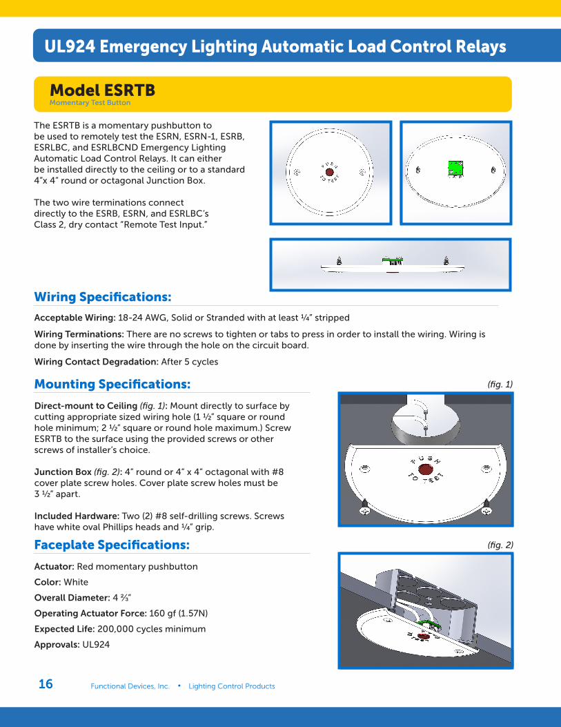
Acceptable Wiring: 18-24 AWG, Solid or Stranded with at least ¼” stripped
Wiring Terminations: There are no screws to tighten or tabs to press in order to install the wiring. Wiring is done by inserting the wire through the hole on the circuit board.
Wiring Contact Degradation: After 5 cycles
Wiring Specifications:
Direct-mount to Ceiling (fig. 1): Mount directly to surface by cutting appropriate sized wiring hole (1 ½” square or round hole minimum; 2 ½” square or round hole maximum.) Screw ESRTB to the surface using the provided screws or other screws of installer’s choice.
Junction Box (fig. 2): 4” round or 4” x 4” octagonal with #8 cover plate screw holes. Cover plate screw holes must be 3 ½” apart.
Included Hardware: Two (2) #8 self-drilling screws. Screws have white oval Phillips heads and ¼” grip.
Mounting Specifications:
Actuator: Red momentary pushbutton
Color: White
Overall Diameter: 4 ⅔”
Operating Actuator Force: 160 gf (1.57N)
Expected Life: 200,000 cycles minimum
Approvals: UL924
Faceplate Specifications:
(fig. 1)
(fig. 2)
The ESRTB is a momentary pushbutton to be used to remotely test the ESRN, ESRN-1, ESRB, ESRLBC, and ESRLBCND Emergency Lighting Automatic Load Control Relays. It can either be installed directly to the ceiling or to a standard 4”x 4” round or octagonal Junction Box.
The two wire terminations connect directly to the ESRB, ESRN, and ESRLBC’s Class 2, dry contact “Remote Test Input.”
UL924 Emergency Lighting Automatic Load Control Relays
Model ESRTBMomentary Test Button
www.functionaldevices.com/lighting-controls • (800) 888-5538 17
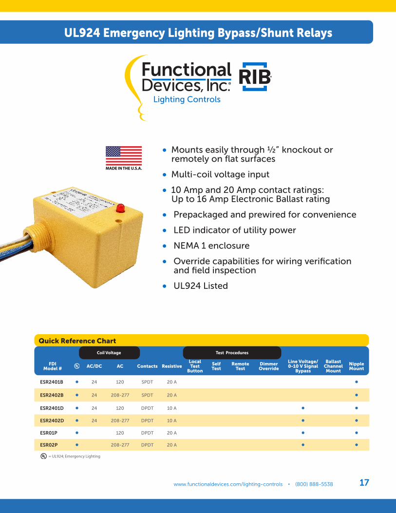
• Mounts easily through ½” knockout or remotely on flat surfaces
• Multi-coil voltage input
• 10 Amp and 20 Amp contact ratings: Up to 16 Amp Electronic Ballast rating
• Prepackaged and prewired for convenience
• LED indicator of utility power
• NEMA 1 enclosure
• Override capabilities for wiring verification and field inspection
• UL924 Listed
Coil Voltage Test Procedures
UL924 Emergency Lighting Bypass/Shunt Relays
= UL924; Emergency Lighting
Quick Reference Chart
FDI Model # AC/DC AC Contacts Resistive
Local Test
Button
Self Test
Remote Test
Dimmer Override
Line Voltage/0-10 V Signal
Bypass
Ballast Channel Mount
Nipple Mount
ESR2401B • 24 120 SPDT 20 A •
ESR2402B • 24 208-277 SPDT 20 A •
ESR2401D • 24 120 DPDT 10 A • •
ESR2402D • 24 208-277 DPDT 10 A • •
ESR01P • 120 DPDT 20 A • •
ESR02P • 208-277 DPDT 20 A • •
UL924 Emergency Lighting Bypass/Shunt Relays
www.functionaldevices.com/lighting-controls • (800) 888-5538Functional Devices, Inc. • Lighting Control Products18
# Relays & Contact Type:Expected Relay Life:
Operating Temperature:Operate Time:
Relay Status:Dimensions:
Wires:Approvals:
Housing Rating:Gold Flash:
Override (Test Switch):
One (1) SPDT Continuous Duty Coil10 million cycles minimum mechanical-30 to 140° F18msLED On = Normal power present2.30˝ x 3.20˝ x 1.80˝ with .50˝ NPT Nipple16˝, 600V RatedUL Listed, UL924, C-UL, CE, RoHS UL Accepted for Use in Plenum, NEMA 1NoNo
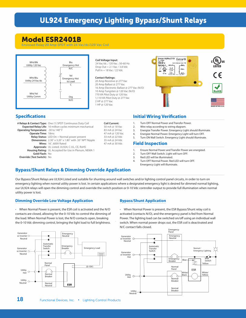
Wht/BlkUtility 120 Vac
Wht/BluUtility 24 Vac/dc
Wht/YelUtility Comm
BluEmergency Hot
N/C
YelEmergency Hot
to LoadC
OrgN/O
Coil Current: 50 mA @ 18 Vac83 mA @ 24 Vac47 mA @ 120 Vac33 mA @ 22 Vdc 35 mA @ 24 Vdc47 mA @ 30 Vdc
Coil Voltage Input: 24 Vac/dc ; 120 Vac ; 50-60 HzDrop Out = 2.1 Vac / 3.8 VdcPull In = 18 Vac / 22 Vdc
Specifications
Contact Ratings: 20 Amp Resistive @ 277 Vac20 Amp Ballast @ 277 Vac 16 Amp Electronic Ballast @ 277 Vac (N/O) 10 Amp Tungsten @ 120 Vac (N/O)770 VA Pilot Duty @ 120 Vac1,110 VA Pilot Duty @ 277 Vac2 HP @ 277 Vac1 HP @ 120 Vac
Initial Wiring Verification 1. Turn OFF Normal Power and Transfer Power.2. Wire relay according to wiring diagram.3. Energize Transfer Power. Emergency Light should illuminate.4. Energize Normal Power. Emergency Light will turn OFF.5. Turn ON Wall Switch. Emergency Light should illuminate.
Field Inspection 1. Ensure Normal Power and Transfer Power are energized.2. Turn OFF Wall Switch. Light will turn OFF.3. Red LED will be illuminated.4. Turn OFF Normal Power. Red LED will turn OFF. Emergency Light will illuminate.
Bypass/Shunt Relays & Dimming Override Application
Our Bypass/Shunt Relays are UL924 Listed and suitable for shunting around wall switches and/or lighting control panel circuits, in order to turn on emergency lighting when normal utility power is lost. In certain applications where a designated emergency light is desired for dimmed normal lighting, our UL924 relays will open the dimming control and override the switch position or 0-10 Vdc controller output to provide full illumination when normal utility power is lost.
UL924 Emergency Lighting Bypass/Shunt Relays
AutomaticTransfer
Switch
Generatoror Inverter
Neutral
Generatoror Inverter
Hot
UtilityHot
UtilityNeutral Normal
Neutral
NormalPanel
EmergencyBreaker
EmergencyNeutral
NormalBreaker
Emergency Load
ESR
DimmerControl
(0-10V)
Generatoror Inverter
Neutral
Generatoror Inverter
Neutral
UtilityHot
UtilityNeutral Normal
Neutral
NormalBreaker
NormalPanel
AutomaticTransferSwitch
EmergencyNeutral
EmergencyBreaker Emergency Load
(0-10V)
Dimming Override Low Voltage Application
• When Normal Power is present, the ESR coil is activated and the N/O contacts are closed, allowing for the 0-10 Vdc to control the dimming of the load. When Normal Power is lost, the N/O contacts open, breaking the 0-10 Vdc dimming control, bringing the light load to full brightness.
Bypass/Shunt Application
• When Normal Power is present, the ESR Bypass/Shunt relay coil is activated (contacts N/O), and the emergency panel is fed from Normal Power. The lighting load can be switched on/off using an individual wall switch. When normal power drops out, the ESR coil is deactivated and N/C contact falls closed.
Model ESR2401BEnclosed Relay 20 Amp SPDT with 24 Vac/dc/120 Vac Coil
AutomaticTransfer
Switch
Generatoror Inverter
Neutral
Generatoror Inverter
Hot
UtilityHot
UtilityNeutral
NormalNeutral
NormalPanel
EmergencyBreaker
WallSwitch
EmergencyNeutral
EmergencyPanel
NormalBreaker
Normal /Emergency Lighting
ESRWhite/Black
White/Yellow
Blue
Yellow
Generatoror Inventer
Neutral
Generatoror Inventer
Hot
UtilityHot
UtilityNeutral
AutomaticTransferSwitch
EmergencyPanel
EmergencyNeutral
EmergencyBreaker
NormalPanel
NormalBreaker
Yellow
Blue
White/Yellow
White/Black
WallSwitch
NormalBreaker
www.functionaldevices.com/lighting-controls • (800) 888-5538 19
# Relays & Contact Type:Expected Relay Life:
Operating Temperature:Operate Time:
Relay Status:Dimensions:
Wires:Approvals:
Housing Rating:Gold Flash:
Override (Test Switch):
One (1) SPDT Continuous Duty Coil10 million cycles minimum mechanical-30 to 140° F18msLED On = Normal power present2.30˝ x 3.20˝ x 1.80˝ with .50˝ NPT Nipple16˝, 600V RatedUL Listed, UL924, C-UL, CE, RoHS UL Accepted for Use in Plenum, NEMA 1NoNo
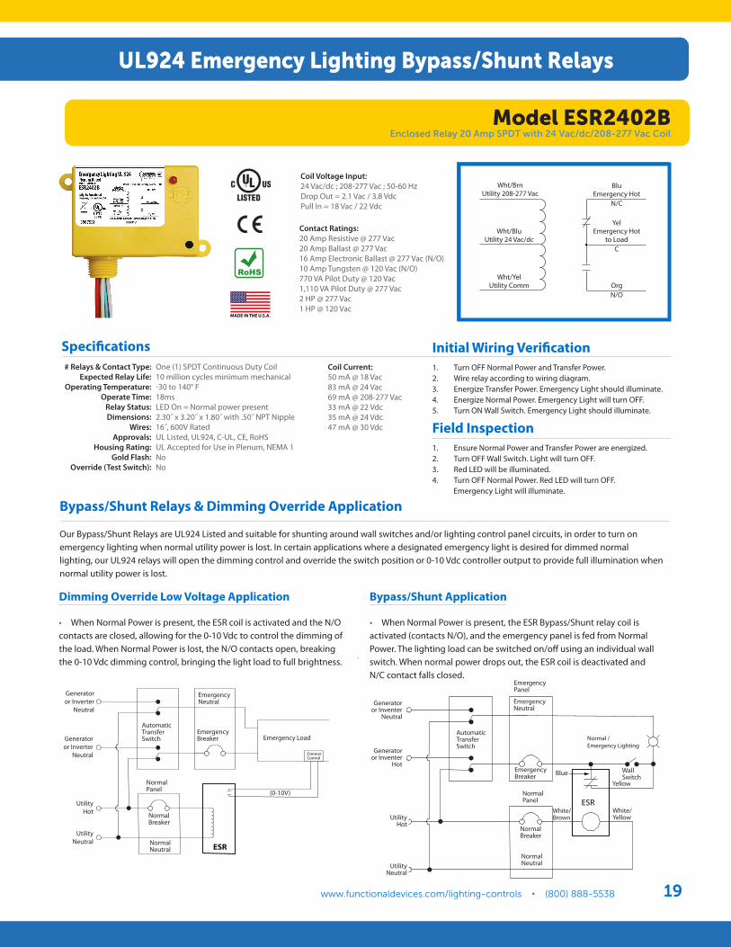
Contact Ratings: 20 Amp Resistive @ 277 Vac20 Amp Ballast @ 277 Vac 16 Amp Electronic Ballast @ 277 Vac (N/O) 10 Amp Tungsten @ 120 Vac (N/O)770 VA Pilot Duty @ 120 Vac1,110 VA Pilot Duty @ 277 Vac2 HP @ 277 Vac1 HP @ 120 Vac
Coil Current: 50 mA @ 18 Vac83 mA @ 24 Vac69 mA @ 208-277 Vac33 mA @ 22 Vdc 35 mA @ 24 Vdc47 mA @ 30 Vdc
Coil Voltage Input: 24 Vac/dc ; 208-277 Vac ; 50-60 HzDrop Out = 2.1 Vac / 3.8 VdcPull In = 18 Vac / 22 Vdc
Wht/BrnUtility 208-277 Vac
Wht/BluUtility 24 Vac/dc
Wht/YelUtility Comm
BluEmergency Hot
N/C
YelEmergency Hot
to LoadC
OrgN/O
Specifications
Field Inspection 1. Ensure Normal Power and Transfer Power are energized.2. Turn OFF Wall Switch. Light will turn OFF.3. Red LED will be illuminated.4. Turn OFF Normal Power. Red LED will turn OFF. Emergency Light will illuminate.
UL924 Emergency Lighting Bypass/Shunt Relays
AutomaticTransfer
Switch
Generatoror Inverter
Neutral
Generatoror Inverter
Hot
UtilityHot
UtilityNeutral
NormalNeutral
NormalPanel
EmergencyBreaker
WallSwitch
EmergencyNeutral
EmergencyPanel
NormalBreaker
Normal /Emergency Lighting
ESRWhite/Black
White/Yellow
Blue
Yellow
AutomaticTransfer
Switch
Generatoror Inverter
Neutral
Generatoror Inverter
Hot
UtilityHot
UtilityNeutral Normal
Neutral
NormalPanel
EmergencyBreaker
EmergencyNeutral
NormalBreaker
Emergency Load
ESR
DimmerControl
(0-10V)
Generatoror Inverter
Neutral
Generatoror Inverter
Neutral
UtilityHot
UtilityNeutral Normal
Neutral
NormalBreaker
NormalPanel
AutomaticTransferSwitch
EmergencyNeutral
EmergencyBreaker Emergency Load
(0-10V)
Generatoror Inventer
Neutral
Generatoror Inventer
Hot
UtilityHot
UtilityNeutral
AutomaticTransferSwitch
EmergencyPanel
EmergencyNeutral
EmergencyBreaker
NormalPanel
NormalBreaker
NormalNeutral
Yellow
Blue
White/Yellow
White/Brown
WallSwitch
Dimming Override Low Voltage Application
• When Normal Power is present, the ESR coil is activated and the N/O contacts are closed, allowing for the 0-10 Vdc to control the dimming of the load. When Normal Power is lost, the N/O contacts open, breaking the 0-10 Vdc dimming control, bringing the light load to full brightness.
Bypass/Shunt Application
• When Normal Power is present, the ESR Bypass/Shunt relay coil is activated (contacts N/O), and the emergency panel is fed from Normal Power. The lighting load can be switched on/off using an individual wall switch. When normal power drops out, the ESR coil is deactivated and N/C contact falls closed.
Model ESR2402BEnclosed Relay 20 Amp SPDT with 24 Vac/dc/208-277 Vac Coil
Bypass/Shunt Relays & Dimming Override Application
Our Bypass/Shunt Relays are UL924 Listed and suitable for shunting around wall switches and/or lighting control panel circuits, in order to turn on emergency lighting when normal utility power is lost. In certain applications where a designated emergency light is desired for dimmed normal lighting, our UL924 relays will open the dimming control and override the switch position or 0-10 Vdc controller output to provide full illumination when normal utility power is lost.
Initial Wiring Verification 1. Turn OFF Normal Power and Transfer Power.2. Wire relay according to wiring diagram.3. Energize Transfer Power. Emergency Light should illuminate.4. Energize Normal Power. Emergency Light will turn OFF.5. Turn ON Wall Switch. Emergency Light should illuminate.
www.functionaldevices.com/lighting-controls • (800) 888-5538Functional Devices, Inc. • Lighting Control Products20
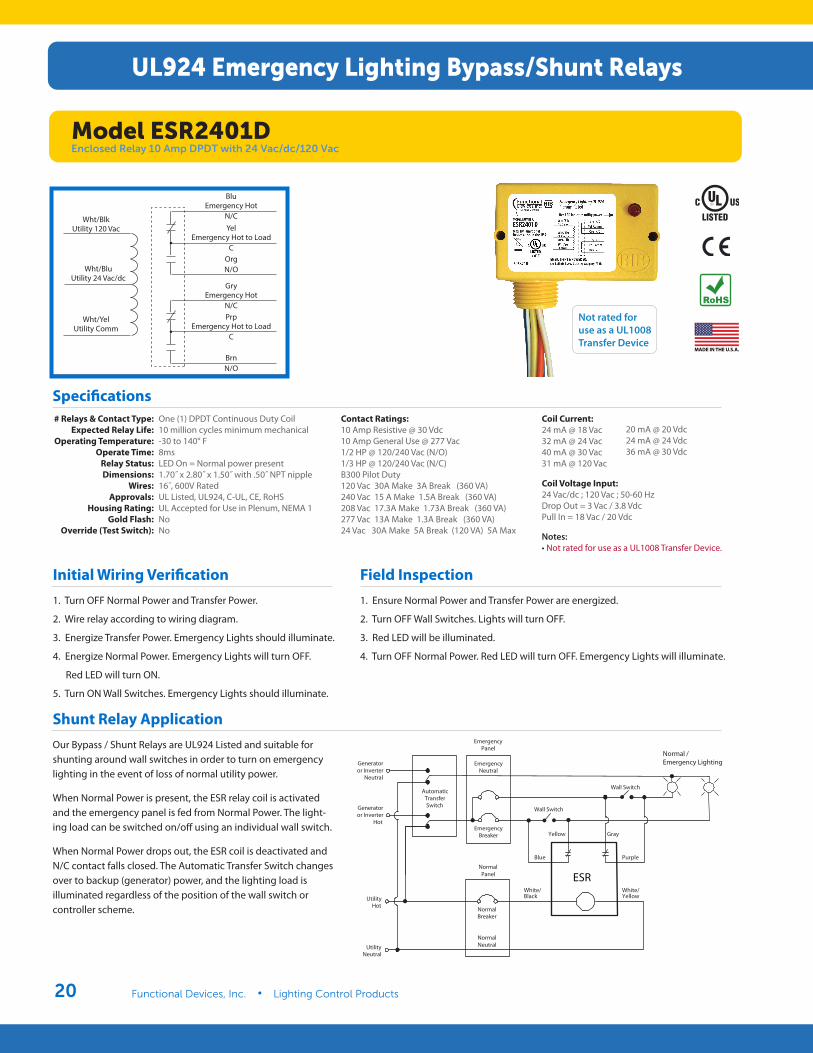
BluEmergency Hot
N/CYel
Emergency Hot to LoadC
OrgN/O
GryEmergency Hot
N/CPrp
Emergency Hot to LoadC
BrnN/O
Wht/BlkUtility 120 Vac
Wht/BluUtility 24 Vac/dc
Wht/YelUtility Comm
# Relays & Contact Type:Expected Relay Life:
Operating Temperature:Operate Time:
Relay Status:Dimensions:
Wires:Approvals:
Housing Rating:Gold Flash:
Override (Test Switch):
One (1) DPDT Continuous Duty Coil10 million cycles minimum mechanical-30 to 140° F8msLED On = Normal power present1.70˝ x 2.80˝ x 1.50˝ with .50˝ NPT nipple16˝, 600V RatedUL Listed, UL924, C-UL, CE, RoHS UL Accepted for Use in Plenum, NEMA 1NoNo
Contact Ratings: 10 Amp Resistive @ 30 Vdc10 Amp General Use @ 277 Vac1/2 HP @ 120/240 Vac (N/O)1/3 HP @ 120/240 Vac (N/C)B300 Pilot Duty120 Vac 30A Make 3A Break (360 VA)240 Vac 15 A Make 1.5A Break (360 VA)208 Vac 17.3A Make 1.73A Break (360 VA)277 Vac 13A Make 1.3A Break (360 VA)24 Vac 30A Make 5A Break (120 VA) 5A Max
Coil Current: 24 mA @ 18 Vac32 mA @ 24 Vac40 mA @ 30 Vac31 mA @ 120 Vac
Coil Voltage Input: 24 Vac/dc ; 120 Vac ; 50-60 HzDrop Out = 3 Vac / 3.8 VdcPull In = 18 Vac / 20 Vdc
Notes: • Not rated for use as a UL1008 Transfer Device.
20 mA @ 20 Vdc 24 mA @ 24 Vdc36 mA @ 30 Vdc
Not rated for use as a UL1008 Transfer Device
Specifications
Initial Wiring Verification 1. Turn OFF Normal Power and Transfer Power.
2. Wire relay according to wiring diagram.
3. Energize Transfer Power. Emergency Lights should illuminate.
4. Energize Normal Power. Emergency Lights will turn OFF.
Red LED will turn ON.
5. Turn ON Wall Switches. Emergency Lights should illuminate.
Field Inspection 1. Ensure Normal Power and Transfer Power are energized.
2. Turn OFF Wall Switches. Lights will turn OFF.
3. Red LED will be illuminated.
4. Turn OFF Normal Power. Red LED will turn OFF. Emergency Lights will illuminate.
EmergencyPanel
Generatoror Inverter
Neutral
Generatoror Inverter
Hot
AutomaticTransferSwitch
EmergencyBreaker
Wall Switch
UtilityHot
NormalBreaker
UtilityNeutral
NormalNeutral
NormalPanel
EmergencyNeutral
Wall Switch
Normal /Emergency Lighting
ESR
Gray
Blue
Yellow
Purple
White/Black
White/Yellow
Shunt Relay ApplicationOur Bypass / Shunt Relays are UL924 Listed and suitable for shunting around wall switches in order to turn on emergency lighting in the event of loss of normal utility power.
When Normal Power is present, the ESR relay coil is activated and the emergency panel is fed from Normal Power. The light-ing load can be switched on/off using an individual wall switch.
When Normal Power drops out, the ESR coil is deactivated and N/C contact falls closed. The Automatic Transfer Switch changes over to backup (generator) power, and the lighting load is illuminated regardless of the position of the wall switch or controller scheme.
UL924 Emergency Lighting Bypass/Shunt Relays
Model ESR2401DEnclosed Relay 10 Amp DPDT with 24 Vac/dc/120 Vac
www.functionaldevices.com/lighting-controls • (800) 888-5538 21
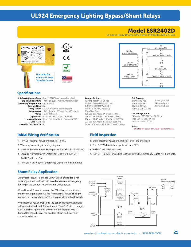
Wht/BrnUtility 208-277 Vac
Wht/BluUtility 24 Vac/dc
Wht/YelUtility Comm
BluEmergency Hot
N/CYel
Emergency Hot to LoadC
OrgN/O
GryEmergency Hot
N/CPrp
Emergency Hot to LoadC
BrnN/O
# Relays & Contact Type:Expected Relay Life:
Operating Temperature:Operate Time:
Relay Status:Dimensions:
Wires:Approvals:
Housing Rating:Gold Flash:
Override (Test Switch):
One (1) DPDT Continuous Duty Coil10 million cycles minimum mechanical-30 to 140° F8msLED On = Normal power present1.70˝ x 2.80˝ x 1.50˝ with .50˝ NPT nipple16˝, 600V RatedUL Listed, UL924, C-UL, CE, RoHS UL Accepted for Use in Plenum, NEMA 1NoNo
Contact Ratings: 10 Amp Resistive @ 30 Vdc10 Amp General Use @ 277 Vac1/2 HP @ 120/240 Vac (N/O)1/3 HP @ 120/240 Vac (N/C)B300 Pilot Duty120 Vac 30A Make 3A Break (360 VA)240 Vac 15 A Make 1.5A Break (360 VA)208 Vac 17.3A Make 1.73A Break (360 VA)277 Vac 13A Make 1.3A Break (360 VA)24 Vac 30A Make 5A Break (120 VA) 5A Max
Coil Current: 24 mA @ 18 Vac32 mA @ 24 Vac40 mA @ 30 Vac36 mA @ 208-277 Vac
Coil Voltage Input: 24 Vac/dc ; 208-277 Vac ; 50-60 HzDrop Out = 3 Vac / 3.8 VdcPull In = 18 Vac / 20 Vdc
Specifications
20 mA @ 20 Vdc 24 mA @ 24 Vdc36 mA @ 30 Vdc
Notes: • Not rated for use as a UL1008 Transfer Device.
Not rated for use as a UL1008 Transfer Device
Shunt Relay ApplicationOur Bypass / Shunt Relays are UL924 Listed and suitable for shunting around wall switches in order to turn on emergency lighting in the event of loss of normal utility power.
When Normal Power is present, the ESR relay coil is activated and the emergency panel is fed from Normal Power. The light-ing load can be switched on/off using an individual wall switch.
When Normal Power drops out, the ESR coil is deactivated and N/C contact falls closed. The Automatic Transfer Switch changes over to backup (generator) power, and the lighting load is illuminated regardless of the position of the wall switch or controller scheme.
Initial Wiring Verification 1. Turn OFF Normal Power and Transfer Power.
2. Wire relay according to wiring diagram.
3. Energize Transfer Power. Emergency Lights should illuminate.
4. Energize Normal Power. Emergency Lights will turn OFF.
Red LED will turn ON.
5. Turn ON Wall Switches. Emergency Lights should illuminate.
Field Inspection 1. Ensure Normal Power and Transfer Power are energized.
2. Turn OFF Wall Switches. Lights will turn OFF.
3. Red LED will be illuminated.
4. Turn OFF Normal Power. Red LED will turn OFF. Emergency Lights will illuminate.
EmergencyPanel
Generatoror Inverter
Neutral
Generatoror Inverter
Hot
AutomaticTransferSwitch
EmergencyBreaker
Wall Switch
UtilityHot
NormalBreaker
UtilityNeutral
NormalNeutral
NormalPanel
EmergencyNeutral
Wall Switch
Normal /Emergency Lighting
ESR
Gray
Blue
Yellow
Purple
White/Brown
White/Yellow
UL924 Emergency Lighting Bypass/Shunt Relays
Model ESR2402DEnclosed Relay 10 Amp DPDT with 24 Vac/dc/208-277 Vac
www.functionaldevices.com/lighting-controls • (800) 888-5538Functional Devices, Inc. • Lighting Control Products22
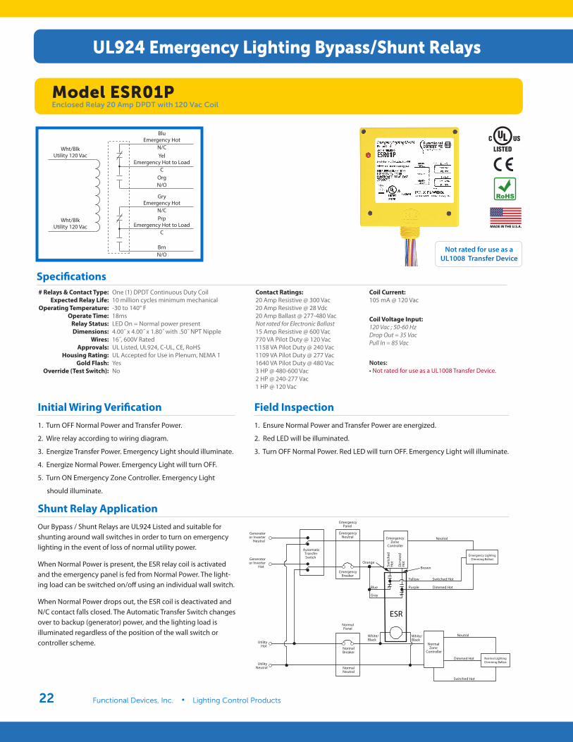
Wht/BlkUtility 120 Vac
Wht/BlkUtility 120 Vac
BluEmergency Hot
N/CYel
Emergency Hot to LoadC
OrgN/O
GryEmergency Hot
N/CPrp
Emergency Hot to LoadC
BrnN/O
Contact Ratings:20 Amp Resistive @ 300 Vac20 Amp Resistive @ 28 Vdc20 Amp Ballast @ 277-480 VacNot rated for Electronic Ballast15 Amp Resistive @ 600 Vac770 VA Pilot Duty @ 120 Vac1158 VA Pilot Duty @ 240 Vac1109 VA Pilot Duty @ 277 Vac1640 VA Pilot Duty @ 480 Vac3 HP @ 480-600 Vac2 HP @ 240-277 Vac1 HP @ 120 Vac
Coil Current: 105 mA @ 120 Vac
Coil Voltage Input: 120 Vac ; 50-60 HzDrop Out = 35 VacPull In = 85 Vac
# Relays & Contact Type:Expected Relay Life:
Operating Temperature:Operate Time:
Relay Status:Dimensions:
Wires:Approvals:
Housing Rating:Gold Flash:
Override (Test Switch):
One (1) DPDT Continuous Duty Coil10 million cycles minimum mechanical-30 to 140° F18msLED On = Normal power present4.00˝ x 4.00˝ x 1.80˝ with .50˝ NPT Nipple16˝, 600V RatedUL Listed, UL924, C-UL, CE, RoHS UL Accepted for Use in Plenum, NEMA 1YesNo
Notes: • Not rated for use as a UL1008 Transfer Device.
Not rated for use as a UL1008 Transfer Device
Specifications
Initial Wiring Verification 1. Turn OFF Normal Power and Transfer Power.
2. Wire relay according to wiring diagram.
3. Energize Transfer Power. Emergency Light should illuminate.
4. Energize Normal Power. Emergency Light will turn OFF.
5. Turn ON Emergency Zone Controller. Emergency Light
should illuminate.
Field Inspection 1. Ensure Normal Power and Transfer Power are energized.
2. Red LED will be illuminated.
3. Turn OFF Normal Power. Red LED will turn OFF. Emergency Light will illuminate.
Shunt Relay ApplicationOur Bypass / Shunt Relays are UL924 Listed and suitable for shunting around wall switches in order to turn on emergency lighting in the event of loss of normal utility power.
When Normal Power is present, the ESR relay coil is activated and the emergency panel is fed from Normal Power. The light-ing load can be switched on/off using an individual wall switch.
When Normal Power drops out, the ESR coil is deactivated and N/C contact falls closed. The Automatic Transfer Switch changes over to backup (generator) power, and the lighting load is illuminated regardless of the position of the wall switch or controller scheme.
Utility
Neutral
EmergencyPanel
Generatoror Inverter
Neutral
Generatoror Inverter
Controller
Hot
Automatic
Dimmed Hot
TransferSwitch
Normal
Emergency
Panel
BreakerSwitched Hot
Normal Lighting
Dimmed Hot
Dimming Ballast
Emergency
Switc
hed
Neutral Emergency
Dim
med
Zone
Hot
Controller
Emergency LightingDimming Ballast
Neutral
Neutral
UtilityHot
NormalBreaker
Neutral
NormalZone
Normal
Hot
Switched Hot
ESR
Yellow
Purple
Brown
Gray
Blue
Orange
White/Black
White/Black
UL924 Emergency Lighting Bypass/Shunt Relays
Model ESR01PEnclosed Relay 20 Amp DPDT with 120 Vac Coil
www.functionaldevices.com/lighting-controls • (800) 888-5538 23
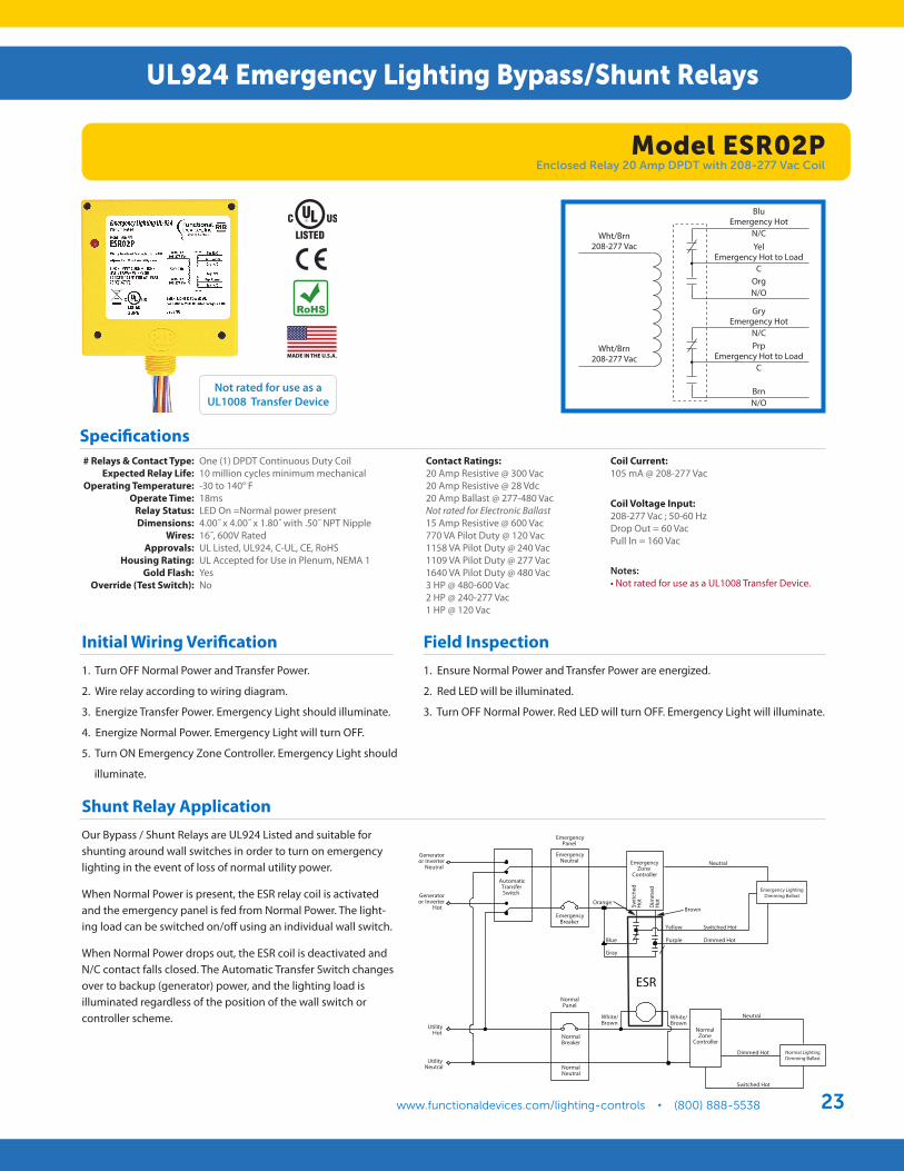
# Relays & Contact Type:Expected Relay Life:
Operating Temperature:Operate Time:
Relay Status:Dimensions:
Wires:Approvals:
Housing Rating:Gold Flash:
Override (Test Switch):
One (1) DPDT Continuous Duty Coil10 million cycles minimum mechanical-30 to 140° F18msLED On =Normal power present4.00˝ x 4.00˝ x 1.80˝ with .50˝ NPT Nipple16˝, 600V RatedUL Listed, UL924, C-UL, CE, RoHS UL Accepted for Use in Plenum, NEMA 1YesNo
Contact Ratings: 20 Amp Resistive @ 300 Vac20 Amp Resistive @ 28 Vdc20 Amp Ballast @ 277-480 VacNot rated for Electronic Ballast15 Amp Resistive @ 600 Vac770 VA Pilot Duty @ 120 Vac1158 VA Pilot Duty @ 240 Vac1109 VA Pilot Duty @ 277 Vac1640 VA Pilot Duty @ 480 Vac3 HP @ 480-600 Vac2 HP @ 240-277 Vac1 HP @ 120 Vac
Coil Current: 105 mA @ 208-277 Vac
Coil Voltage Input: 208-277 Vac ; 50-60 HzDrop Out = 60 VacPull In = 160 Vac
Specifications
Notes: • Not rated for use as a UL1008 Transfer Device.
Initial Wiring Verification 1. Turn OFF Normal Power and Transfer Power.
2. Wire relay according to wiring diagram.
3. Energize Transfer Power. Emergency Light should illuminate.
4. Energize Normal Power. Emergency Light will turn OFF.
5. Turn ON Emergency Zone Controller. Emergency Light should
illuminate.
Field Inspection 1. Ensure Normal Power and Transfer Power are energized.
2. Red LED will be illuminated.
3. Turn OFF Normal Power. Red LED will turn OFF. Emergency Light will illuminate.
Shunt Relay ApplicationOur Bypass / Shunt Relays are UL924 Listed and suitable for shunting around wall switches in order to turn on emergency lighting in the event of loss of normal utility power.
When Normal Power is present, the ESR relay coil is activated and the emergency panel is fed from Normal Power. The light-ing load can be switched on/off using an individual wall switch.
When Normal Power drops out, the ESR coil is deactivated and N/C contact falls closed. The Automatic Transfer Switch changes over to backup (generator) power, and the lighting load is illuminated regardless of the position of the wall switch or controller scheme.
Not rated for use as a UL1008 Transfer Device
Utility
Neutral
EmergencyPanel
Generatoror Inverter
Neutral
Generatoror Inverter
Controller
Hot
Automatic
Dimmed Hot
TransferSwitch
Normal
Emergency
Panel
BreakerSwitched Hot
Normal Lighting
Dimmed Hot
Dimming Ballast
Emergency
Switc
hed
Neutral Emergency
Dim
med
Zone
Hot
Controller
Emergency LightingDimming Ballast
Neutral
Neutral
UtilityHot
NormalBreaker
Neutral
NormalZone
Normal
Hot
Switched Hot
ESR
Yellow
Purple
Brown
Gray
Blue
Orange
White/Brown
White/Brown
Wht/Brn208-277 Vac
Wht/Brn208-277 Vac
BluEmergency Hot
N/CYel
Emergency Hot to LoadC
OrgN/O
GryEmergency Hot
N/CPrp
Emergency Hot to LoadC
BrnN/O
UL924 Emergency Lighting Bypass/Shunt Relays
Model ESR02PEnclosed Relay 20 Amp DPDT with 208-277 Vac Coil
Functional Devices, Inc.101 Commerce Drive, PO Box 437, Sharpsville, Indiana 46068
Sales: 800.888.5538Office: 765.883.5538
Fax: 765.883.7505Email: [email protected]
Website: www.functionaldevices.com
CA2773 9060-1067