uIII guiIo~
61
-Ai27 874 MONOCHROMATIC HIGH-SPEED PHOTOGRAPHY OF SOLID ROCKET /i PROPELLANT COMBUSTION(U) NAVRL POSTGRRDUATE SCHOOL MONTEREY CA R J EDINGTON MAR 83 F846ii-83-X-810 UNCLASSIFIED F/G 21/2 NL EhhmohmohmoiE ,EIIEIlIEEI uIII guiIo~
Transcript of uIII guiIo~

-Ai27 874 MONOCHROMATIC HIGH-SPEED PHOTOGRAPHY OF SOLID ROCKET /iPROPELLANT COMBUSTION(U) NAVRL POSTGRRDUATE SCHOOLMONTEREY CA R J EDINGTON MAR 83 F846ii-83-X-810
UNCLASSIFIED F/G 21/2 NL
EhhmohmohmoiE,EIIEIlIEEIuIII guiIo~

L Q
.- *12
~JjW-- 3.6
MICROCOPY RESOLUTION TEST CHARTNATIONAL BUREAU OF STANDARDS tART-A

NAVAL POSTGRADUATE SCHOOLt Monterey, California
THESISMONOCHROMATIC HIGH-SPEED PHOTOGRAPHYOF SOLID ROCKET PROPELLANT COMBUSTION
by
Ronald James Edington
March 1983
j Thesis Advisor: D. W. Netzer
Approved for public release; distribution unlimited
05-

SacunsTv cLASsiUecATion or THIS PA&: (when Daeed 100_________111___
REPORT DOCUMENTATION PAGE BEFRE 2C3PEN(,. FRMM'KOR UM413.1 GOVT ACCESSION No. I. RCPCHi'CAALOG .dMCA
4. TITLE (410ISd SSEU#I) S. TYPE OF *ePOu'W *qoC.Tl&Master's Thesis
Monochromatic High-Speed Photography of March 1983Solid Rocket Propellant Combustion * EFRIOOG EOiNNE
7. AuTwOR,.) S.CONTRMACT OR %nAN&IT NuR
Ronald James Edington 4183x00
9. 0*ERFORMING ORGANIZATION NAME AND O CS is. O"GRAud 1;.&W91 0QOjfC? ASAREA A woRK V~iN&4UECS
Naval Postgraduate SchoolMonterey, California 93940
it. CONTROLLING OFFICE NAMC AND A000988 Qi. REPORT DATE
Air ForcB 1kCket Propulsion Laboratorv March 1983E&qards AFB, California 93523 i."mef u OF PAGES1
-. moNiTORING AGEfNCY MNME AOOR9ESSII 40#00mt SPOW CoNInvuMS Off60) 15. 11CUR11 V CL ASS. 'Of thod --400.
W4 Unclassified
I$. OISYRIGUTION STATEMENT (of WDe Repoht
Approved for public release, distribution unlimited.
17. OlSTRIDUTIOn STATEMNT (of the 868&091 400eced 14 8104k it, I -W NOR asPe)
18. SuPPLEMENTARY NOTEKS
IS. KEY woROS (Ca.URnute en frms Wdo to Rodosa ow idIei or 6eek .beW)
Monochromatic High-Speed Photography, Solid Rocket PropellantCombustion
20. AGSTA*T (CARIONO OR e6~90 Side ff 00690eM 410 fy 14I I WA 1k 00106W
Eight composite solid propellant formulations containingvarying diameter and weight percentages of metallic particleswere burned in strand form in two different nitrogen purged
6 *' combustion bombs at a pressure of 500 psi. High-speed cinemo-tography was used with an argon laser as the primary monochro-matic liqht source. Two illumination approaches were tried,
V' backlighting and frontlighting. Careful examination of the
Do Foa173mIIOOIOVSSUSL? Unclassified V
S/N 012014 001 gCURITY CLASSIICATION OF T"18S PAGE (IIbaleD016

gu T916 asOs&ea#eu %.#ae A...._
backlighting films revealed that the flame envelopes surround-
ing the particles could be eliminated, and that the trueparticle size could be obtained. However, Schlieren effectsobscurred much of the information which was available on thefilm. The frontlighting technique eliminated. the Schliereneffects and allowed good particle behavioral data to beobtained, but the reflected monochromatic licrht was notsufficient to allow true particle diarreters to be taken.
2.7
-Accesston For1'T'' C,*A&I
" DT.7 C T.B7•.U 'ennoune'ed El
; ,'-In :'l t P, d e
I- A- / r11
r i Scaj.
aL
DD ForiM 1473 Unclassified
S/r 01A'Ifl4-6601 2 *geMthV CLAgmvIgATIGI gO TWO$ 0a4M% O * be.. m.edi
Approved for public release, distribution unlimited
Monochromatic High-Speed Photography ofSolid Rocket Propellant Combustion
by
Ronald Jeanes EdingtonLieutenant Commander, United States NavyB.S., Northern Illinois University, 1970
Submitted in partial fullfillment of therequirements for the degree of
MASTER OF SCIENCE IN AERONAUTICAL ENGINEERING
from the
NAVAL POSTGRADUATE SCHOOLMarch 1983
Author:
Approved by:
9"hss Advisor
Chairman, Departmen.kof Aeronautics
bean of Science and Engineering
'.
' °3
0°°

ABSTRACT
Eight composite solid propellant formulations containing
varying diameter and weight percentages of metallic particles
* were burned in strand form in two different nitrogen purged
combustion bombs at a pressure of 500 psi. High-speed cine-
motography was used with an argon laser as the primary mono-
chromatic light source. Two illumination approaches were
tried, backlighting and frontlighting. Careful examination
of the backlighting films revealed that the flame envelopes
surrounding the particles could be eliminated and that the
true particle size could be obtained. However, Schlieren
effects obscurred much of the information which was avail-
able on the film. The frontlighting technique eliminated
-the Schlieren effects and allowed good particle behavioral
data to be obtained, but the reflected monochromatic light
was not sufficient to allow true particle diameters to be
taken.
4
40

TABLE OF CONTENTS
I. I T O U T O -- - - - - - - - - - - - - - - - - 10
II. METHOD OF INVESTIGATION--------------------------- 14
III. EXPERIMENTAL APPARATUS---------------------------- 15
A. GENERAL EQUIPMENT DESCRIPTION----------------- 5
B. BACKLIGHTING----------------------------------- 17
C. FRONTLIGHTING---------------------------------- 17
IV. EXPERIMENTAL PROCEDURES--------------------------- 18
A. BACKLIGHTING----------------------------------- 18
B. FRONTLIGHTING---------------------------------- 20
V. RESULTS AND DISCUSSION---------------------------- 23
A. BACKLIGHTING--------------------------------- 23
B. FRONTLIGHTING---------------------------------- 23
VI. CONCLUSIONS AND RECOMMENDATIONS------------------- 28
LIST OF REFERENCES--------------------------------------- 55
INITIAL DISTRIBUTION LIST-------------------------------- 57
5

LIST OF TABLES
I.Propellant Composition------------------------------ 30
* .II. Object Diameter Comparison-------------------------- 31
6

LIST OF FIGURES
1. Laser Set-up ------------------------------------- 32
2. 1200 W Light Source inFrontlighting Set-up ----------------------------- 32
3. 2500 W Light Source in
Frontlighting Set-up 3----------------------------- 3
4. Hycam Camera and Oscillator 33
5. Focus Distance (Lens to Object)Versus Extension Tube Length --------------------- 34
6. Camera Supports ....... 35
7. Strand Positions --------------------------------- 36
8. Control Panel 37
9. Schematic of Combustion BombShowing Principal Dimensions --------------------- 38
S10. Combustion Bomb inBacklighting Set-up 39
11. Schematic of Combustion BombShowing Principal Dimensions --------------------- 40
12. Schematic Showing AngularRelationship of Windows -------------------------- 41
13. Combustion Bomb in Frontlighting Set-up ---------- 42
14. Disk and Motor ----------------------------------- 42
15. Schematic of Disk ShowingPrincipal Dimensions 43
16. Strand Dimensions 44
17. Backlighting Layout
18. Backlighting Planform ---------------------------- 46
19. Frontlighting Layout 47
7

20. Frontlighting Planform ------------- 48-
21. Example of BacklightingResult Using WGS-6A------------------------------- 49
22. Photo Sequence of Burning
WGS-611 Strand------------------------------------- 50
23. Object Diameter References------------------------53
24. Burning Particle Diameter
*Versus Initial Particle Diameter------------------ 54
8

ACKNOWLEDGEMENTS
For her understanding and patience, I would like to say
thank you to my wife. I also would like to thank Professor
D. W. Netzer for his direction and assistance. A thank you
also must go to the Aeronautical Engineering Department
Technicians for their timely assistance in providing some
of the many materials that were needed.
9

I. INTRODUCTION
The propulsion of air-air missiles is generally provided
by a solid propellant rocket motor, with all current naval
air-air missile systems being based on this propulsion method.
References 1-4 present a detailed review of the role an
aluminum additive plays in the performance of solid rocket
motors. Finely powdered aluminum in the range of 1-100
microns is the most widely used metal additive [Ref. 11.
The advantages and disadvantages of aluminum as an additive
are discussed again in Refs. 1-4. Particle size analysis
in solid rocket motor combustion has become a major f.eatu.::e
in the development and validation of current theoretical
models [Refs5. 4 and 5]. The influence of particle size on
propellant performance is complex, and understanding tne
degree of influence often is hampered by ambiguous pa.rticle
size data [Ref. 5].
This thesis was directed at one of the four on-going
methods currently being used at the Naval Postgraduate
School to study solid rocket motor propellant combustion:
(a) High-speed cinematography of burning propellantin strands and 2-D slab configurations,
(b) Post-fire residue collection and examinationusing a scanning electron microscope,
(c) Scattered laser power spectra measurements fordetermining the mean diameter of particles asthey pass through the exhaust nozzle,
10

(d) Holographic image construction of the combustionprocess of burning propellant strands and ofburning propellant slabs in a cross-flow environment.
The use of high-speed cinematography in conjunction with
a high pressure combustion bomb in the study of solid rocket
propellant combustion provides a time-resolved observation
method of a dynamic process with little interference with
the process itself [Ref. 6]. This photography covers pro-
pellant combustion from the surface burning phase until the
agglomerates become obscurred either by the aluminum oxide
smoke (combustion products), or by the interacting flame
envelopes.
The major advantages associated with high-speed photo-
graphy used in conjunction with a combustion bomb are:
(a) The time-varying characteristics can be recordedusing the slow motion and stop action capabilitiesof motion pictures,
(b) The combustion bomb facilitates ease in post-fire
residue collection,
(c) The combustion environment can be easily controlled,
(d) And, the possible magnification of desired spatialdetails.
The major disadvantages associated with high-speed
photography used in conjunction with a combustion bomb are:
(a) The lack of cross-flow in the simulation of arocket motor propellant grain,
(b) A cold inert gas is used to pressurize and purgethe bomb which can have a quenching effect onthe combustion process,
(c) There is no nozzle acceleration due to the lackof a nozzle,
b-1
ii

(d) The depth of field is limited by the magnificationdesired, and
(e) The resolution is limited by the varying and
usually numerous types of optics used.
DiLoreto, [Ref. 2], conducted an investigation at NPS to
study the effects of operating pressure and propellant com-
position on the size and velocity of agglomerates leaving
the burning surface. His investigation used six types of
propellant with a constant percentage, but varying size of
aluminum powder. A scanning electron microscope, (SEM),
was used in conjunction with post-fire residue collection
to provide accurate particle size data for comparison with
those observed in the high-speed photography. A minimum
particle size of approximately 60 microns was observed on
the processed film, although 15 microns could be resolved
during the static camera callibrations. This discrepancy
was attributed tc camera jitter.
Karagounis, [Ref. 31, set out to improve on DiLoreto's
results by
(a) Increasing the magnification,
(b) Using fewer optics, and
(c) Reducing the camera jitter.
The changes improved the obtainable resolution, but
significantly better particle size data could not be
obtained because of the flame sheaths which obscurred the
particles.
In the present investigation, an attempt was made to
eliminate the self-luminous interference by filtering out
12

the combustion light. For high-speed photography (in the
range of 5,000 frames per second), a monochromatic light
source(s) was needed which would provide the necessary
illumination at such high framing rates and magnifications.
For this purpose a laser light source was used because of
its extreme brightness, directionality, and monochromati-
city [Ref. 6]. In addition, high intensity arc lamps also
were used which provided considerable intensity in the
narrow wavelength bands.
The monochromatic property of the laser light source
allows the self-luminous interference to be blocked from
the exposed film by using an appropriate narrow-pass filter
prior to the camera lens. The directionality of the laser
allows for ease of focusing all of the light through the
small windows of the high pressure combustion bombs. The
extreme brightness of the light enables the use of a higher
film speed to "stop" the combustion action.
13

II. METHOD OF INVESTIGATION
Eight composite solid propellant formulations containing
varying diameters and weight percentages of metallic parti-
cles were burned in strand form in two different nitrogen
purged combustion bombs at a pressure of 500 psi. High-
speed cinematography was used with an argon laser as the
primary monochromatic light source. Two illumination
approaches were tried: backlighting, and frontlighting
of the burning propellant strands. The data collected was
correlated with that found in previous work done at the
Naval Postgraduate School.
14
I
III. EXPERIMENTAL APPARATUS
A. GENERAL EQUIPMENT DESCRIPTION
The primary light source used was a Control Laser,
continuous-wave (CW), argon laser, Model 902A, operating
at the 488 nm line. The laser provided between .64 and
.74 watts of power. The laser was operated at 32A maximum
on a 220 VAC line. Water cooling also was required from
an external source. Beamwidth was measured at 2mm, and
required a bi-concave lens to diverge the beam to the
desired width. Figure 1 shows the laser set-t.p. The set-
*.- up provided a full 360 degree coverage in azintuth, but was
limited to .5 inches variation in height.
Two additional light sources were used to augment the
laser light source. For this purpose a SLM-1200 projector
with a 1200 W filament lamp, and an Oriel 2500 W Universal
Arc Lamp Source with a 2500 W Mercury/Xenun arc lamp were
used. An infra-red filter was used between the white light
source and the combustion bomb window to reduce the influence
of the light source on the combustion process. Figures 2
and 3 show the light sources in the experimental set-up.
A Hycam Model K2004E-115 high-speed, 16-mm motion
picture camera was used as the recording apparatus. The
Hycam is capable of operating between zero and 11,000 frames
per second, with 5,000 frames per second being the highest
used, anfi 2,500 the lowest. A Red Lake Millimite TLG-4
15

oscillator set at 1,000 pulses per second was used to provide
timing marks on the film edge on all runs. Figure 4 shows
the camera and oscillato::.
An Elgeet 77 mm/fl.9 lens was used with an extension tube
to provide a focal distance of 2.64 inches (vice the 5 inches
used in Ref. 2). Figure 5 gives the focal distance as a
function of extension tube length. The camera base supports
developed in Ref. 3 were used to reduce camera jitter. They
can be seen in Figure 6.
Strand ignition was accomplished by placing a taught,
thin wire across the strand top surface, and connecting the
wire to electrodes on either side of the strand. The wire
was made of nickel-chromium, 0.008 inches in diameter. A
12 VDC battery, in series with a variable resistor to con-
trol the current through the wire, provided the necessary
ignition current. Figure 7 shows the ignition set-up.
Control of each run was provided from behind a protective
control panel. Ignition, pressurization, and camera initia-
tion could all be controlled from behind this panel. Controls
provided an option of manual camera initiation, or auto
initiation. Auto initiation of the camera could occur after
a suitable time delay to allow for strand ignition. Figure
8 shows the control panel. Two different combustion bombs
F" were used in conjunction with the two lighting techniques
employed.
16

B. BACKLIGHTING
The same combustion bomb used in Ref. 2 (as modified in
Ref.3) was used during the backlighting experiments. Figure
9 is a schematic of this bomb. The bomb provided the necces-
sary working pressure capability and opposing windows for the
backlighting technique. Figure 10 shows the bomb in the
experimental set-up.
C. FRONTLIGHTING
The combustion bomb used for the backlighting technique
could not be used for the frontlighting technique because of
the insufficient number of windows facing the camera. The
con-bustion bomb used for the frontlighting experiments was
the same one used by Kennedy [Ref. 7]. Figures 11 and 12
are schematics of the combustion bomb. Figure 13 shows the
combustion bomb in the frontlighting set-up. Because of
the larger windows in this combustion bomb, the available
pressurization was limited to 500 psi.
A rotating disk was used to present varying illumination
(white light and 488 nm light) to the camera during a single
burn. The disk was made of aluminum with a radius of 4.125
inches and a thickness of 0.23 inches. A Sargent Cone Drive
Stirring Motor was used to rotate the disk at a rate of 1,740
revolutions per minute. Figure 14 shows the motor and disk
in the frontlighting set-up. Figure 15 presents a schematic
of the disk.
17

IV. EXPERIMENTAL PROCEDURES
A. BACKLIGHTING
"The most relevant tests are probably those in which
observations of combustion are made with a propellant having
a few aluminum particles of desired size." [Ref. 1].
With this in mind, initial testing was done using WGS-6A
propellant. Table I lists the propellant formulations used
in this investigation. These propellants were provided by
* the Aerojet Solid Rocket Company, Sacramento, California.
The propellants were cut to strand size as shown in Figure
16. The width varied slightly so as to fill the camera
field of view, but were generally the dimensions as shown.
The cut strands were cemented to stainless steel pedestals,
then placed in a pedestal holder in the middle of the
combustion bomb.
A 2.75 inch extension tube was used with the f/l.9 lens
to give an object distance of 2.64 inches. This placed the
camera lens to within 0.39 inches of the combustion bomb
window. This was the minimum working distance due to the
window mounting screws, and the need to provide room for
the narrow-pass filter to be placed between the lens and
the window. The resolution was 14 jum as determined in
Ref. 3. The lens focus was first fixed on the camera, then
the fine focusing was done by moving the entire camera. A
static focus was made at the start, and the camera position
18
" was recorded so that when the camera was moved back into
position after loading it would be placed in focus.
The magnification was computed to be 1.90X, [Ref. 111.
The effective f-stop due to the magnification was approx-
imately 5.7, [Ref. 8]. This gave a depth of field of
approximately'0.008 inches, [Ref. 9], or 0.2 mn. This was
much smaller than the 2 mm thickness of the strand. The
focus was made on the front surface of the strand, &nd then
moved inward approximately 0.5 mm.
Backlighting was provided by the laser at 488 nmL through
the window opposing the camera viewing window. Laser light
was blocked until just prior to ignition so as to have as
little effect on the combustion process as possible. The
1200 watt projector lamp was used to supplement the laser
light source, and was directed through the side window.
The laser light was first used without modification.
Two types of filtering were later used: (1) spatial
filtering, and (2) diffuse glass. These were placed
between the laser and the combustion bomb.
Runs were attempted at rates between 2500 and 5000
frames per second. The f-stop was varied from f/l.9 to
f/4.6 in an attempt to obtain varying degrees of exposure.
Nitrogen was used as the pressurizing and purging medium.
The bomb was first pressurized from the control panel,
then a purge valve was adjusted to allow the combustion
gasses to escape. Only enough purge was used to provide
191.

a clear view of the strand throughout the combustion process.
Numerous strand burns were made to determine the correct
purge rate.
Strand ignition and camera initiation were accomplished
in the manual mode with a conscious delay in camera initia-
tion to allow for strand ignition. One hundred foot rolls
of Kodak 7250 film were used for all runs. However, only
the last ninety frames provided exposures at the maximum
film rates.
Figures 17 and 18 show the backlighting layout. The
spatial filter and the diffuse glass were never used
together in the same run.
B. FRONTLIGHTING
Because of the larger diameter of the combustion bomb
used for the experiments with Erontlighting, a 2 inch
extension tube had to be used. This, again, put the lens
at the minimum working distance possible. The 2 inch
extension provided a magnification of 1.8. The effective
f-stop in this configuration was 5.3, giving a depth of
field of approximately 0.009 inches, or 0.24 mm. As in
the case of the backlighting technique, this depth of field
was far less than the strand thickness.
The laser light was reflected off a mirror, passed
through a bi-concave lens to expand the beam to the strand
dimensions, and then put through the window next to the
camera. No filtering was done to the laser light. The
20

1200 W white light source was again used as a supplement to
the laser light. It was projected through the same window
as the laser light source at an angle which illuminated as
much of the propellant surface as possible, and not to
interfere with the laser light. The 2500 W white light
source was projected through an IR filter, then through
the side window. The large diameter of the side window
permitted the 2500 W light to be projected in at an angle
which would illuminate the front face of the propellant.
The rotating disk was placed between the camera lens
and the combustion bomb window. The disk provided three
different illuminations of the strand burn to the camera.
The first and primary view of the strand burn was with
illumination by all three light sources and the appropri-
ate narrow-pass filter in front of the camera lens. A
second view was with all three light sources illuminating
the strand surface, but with no narrow-pass filter. The
third view was with just white light illumination and no
laser light and no narrow-pass filter. The disk was spin-
- ning at 1,740 revolutions per minute. With approximately
90 frames available at the maximum film rate, the distance
travelled by the disk was 11.6 inches during the 90 frames.
E The circumference of the disk at the mid-point of the filters
was 22.0 inches. This provided two complete presentations
to the camera. The number of frames per inch of disk travel
was 7.75. Figures 19 and 20 show the front-lighting layout.
21
6 .
All other experimental procedures were identical to
those used with the backlighting technique.
22

V. RESULTS AND DISCUSSION
A. BACKLIGHTING
It was anticipated that the flame sheath, which obscurred
true particle size analysis by high speed photography in
Refs. 2 and 3, could be filtered out using the monochromatic
property of the laser light and an appropriate narrow-pass
filter. It also was believed that the Schlieren effects
associated with a collimated light source would be reduced,
if not eliminated, using a diverging light source and
appropriate filtering. This would leave the shadow of the
particle for the camera to record. Runs were completed as
discussed previously. Figure 21 is an example of the results
of a typical run. This figure is for WGS-6A at 5,000 frames
per second, and f/1.9. Careful examination reveals that the
particle size of approximately 60 microns can be obtained
from the film. However, the Schlieren effects obscurred
much of the information which was available on the film.
Similar results can be found in Refs. 10, 11, and 12. A
different method of lighting was required which would not
be limited by the Schlieren effects.
B. FRONTLIGHTING
The initial set-up for frontlighting was with the laser
as the only light source. At the 5,000 frames per second
film rate required to stop the action of the burn, the laser
23I°q

did not provide enough light in the 488 nm range needed.
The 1200 W light source and the spinning disk were then
added. Again, a little more light in the same range was
needed. The 2500 W light provided the needed light, not
*only in the 488 nm range, but also for the white light
illumination. The disk provided the multiple types of
presentations as seen in the sequence of photos in Figure
22. These photos were taken of WGS-6A at 5,000 frames
per second, and f/l.9.
The nonfiltered sequence of photos shows the burning
particles leaving the surface as documented in Refs. 1-4.
What is different in these photos is the equal number of
particles which are leaving the surface unignited, and then
igniting anywhere up to 4 mm front the surface. Picture
- framing prevented analysis at any greater distance from
the surface. These unignited particles are seen as a bright
ring around a darkened center. This ring continued to get
brighter until the flame sheath engulfed the entire darkened
area. The filtered sequence of pictures provided another
bright ring with a darkened center. The diameter of the
dark area in the filtered sequence was about the same
diameter as the flame sheath in the unfiltered sequence.
Figure 23 is a representation of the different objects seen
in the photos and respective diameter references.
Table II is a comparison of the eight propellants
burned, including the data taken by DiLorettx, [Ref. 2].
DiLoreto, did not test those propellants where N/A appears.
V. 24

Figure 24 is a comparison of the initial powder diameters
versus the burning particle diameters for propellants WGS-5A,
6A, 7, and 7A. Also shown are the data obtained by DiLoreto,
[Ref. 2]. What was not seen by DiLoreto or Karagounis [Ref.
3], were the ringed darkened areas seen in the unfiltered
and the filtered photo sequence. As can be seen in Figure
24, the computed flame sheath diameters closely correlate
with those found by DiLoreto.
Values for Dwc and Dwr in Table II for WGS-7 were not
obtained from the films because of the small particle size.
The unfiltered dark centers could not be resolved. If an
average ratio of the unfiltered dark centers to the initial
powder sizes for WGS-5A, 6A, and 7A is used to predict the
unfiltered dark center size for WGS-7, then the limit of the
resolution capability of the camera was approached.
Propellants WGS-9 and 10 had two and three times the
weight percentage of aluminum respectively, as did WGS-5A,
6A, 7, and 7A. This resulted in a significant increase in
the number of particles, and a recorded continuous flame
all along the strand. The increase in the self-luminous
light also obscurred any particle size information contained
in the photos.
Particle size data from the propellant containing
zirconium could not be obtained from the film because of
the irregular shape of the particles. The non-burning
*4 particles could be seen to tumble after leaving the strand
25

surf ace. The tumbling and the reflected light gave the
appearance of a rapid, rising bubbling action in water.
The tumbling and the irregular shape prevented the taking
of any meaningful data.
The motion picture of the propellant containing graphite
had the same characteristics as the zirconium propellant.
*In addition, because the 7 micron dimension of the 50x20x7
micron graphite was well below the resolution capabilities
of the camera, the particles appeared to pop in and out of
view as they tumbled. The filtered frame had what appeared
to be corner reflections from the platelets, but no defini-
tive data could be taken from the photos.
All the motion pictures taken still had what appeared
to be the result of camera jitter, although not to the
degree experienced in Ref. 2. The jitter was still a
factor in the resolution capabilities of the camera.
The propellants used in this study which had five per-
cent aluminum by weight had the expected burning chara- ter-
istic of the particles immediately leaving the surface
without surface agglomeration. These particles probably
had little, if any, significant oxide coating on their
surfaces. Diameter Dwr (or Dwc) was significantly greater
than the powder size, and therefore was apparently the
diameter of the metal vapor cloud around the molten center.
When the vapor attained sufficient temperature and ignited,
the observed flame diameter was a little bigger, and the
26

6
characteristic Al 203 "tail" was apparent. The cause of the
large outer ring in the filtered pictures is not clear at
this point.
Although the frontlighting technique eliminated the
undesirable Schlieren effects of backlighting, and allowed
good particle behavioral data to be obtained, the reflected
monochromatic light was not sufficient to allow true
particle diameters to be obtained.
27
I-°

VI. CONCLUSIONS AND RECOMMENDATIONS
. . In the test runs using WGS-5A, 6a, and 7A, the unfiltered
bright ring appears to be a veil of metal/metal oxide smoke
as discussed in Ref. 1. The dark area in the unfiltered ring
*-. may be the result of the strictly frontal lighting. It may
be possible to improve significantly the data obtained from
the films by using the 2500 W diffuse light to provide rear
illumination in conjunction with frontlighting provided by
*the argon laser. This would provide better contrasting and
the shadows from rear illumination, with the possibility of
better particle resolution as obtained in the Schlieren
obscurred backlighting films.
The fact that some particles left the surface unignited
is not unusual under an adverse combustion process, [Ref. 1].
The particles later ignited due to the interaction with the
high temperature flame zone.
Meaningful photos might be obtained for propellants
WGS-9 and 10 by stopping down the lens one or two stops.
This would remove some of the self-luminous light, and as
a secondary benefit, would increase the depth of field.
" In order to see the entire surface of zirconium or
graphite particles, it would be necessary to have a better
depth of field because of their irregular shapes. Again,
4 as with propellants WGS-9 and 10, this would mean stopping
28
4!

the lens down one or two stops. Illumination of the filtered
photos would be the limiting factor in how far the lens could
be stopped down.
Camera jitter could be controlled better if the stabliz-
ing bolts were made an integral part of the camera stand,
and were torqued down to engage the metal platform.
29

7"
TABLE I
PROPELLANT COMPOSITION
Propellant Binder Oxidizer* Metal Mean MetalDesignation % Weight % Weight % Weight Diameter, u.m
WGS-5A HTPB AP Al75812 83 5758
WGS-6A HTBP AP Al 45-6212 83 5
HTPB AP AlWGS-7A 183523-27
12 83 5
WGS-9HTPB AP Al237
12 78 1023 7
WGS-10 HTPB AP Al 23-2712 73 15
HTPB AP Zr 23 *Zirconium 14 84 2
Graphite HTPB AP C Approx.14 84 2 50x20x7
* AP is 65% 180 Micron/35% 26 Micron** Irregularly Shaped
** Platelets
30

.W 0' N qw L r- LA Ln en
C- Ln N- C4 N $
C- 0 o t D r-
- - - -o - --
k -- - --
lw 00 %D 4c 4c 4'-f
HL LA en1 (N r-4 0 4' '
E-4 -H 4'r -4_____ w wn 4 )
E4 Q-4
~i 4' 10
E4~4 -K 4' 4
en ' ' 4 4' 0FN w' C44 N' 4't,
cn 4' 1' 4 0 04 A. r
_ w C'- ON 0c B' 4 ' 4' '0
414 444 ' N 0
4 4 t 4t
31

Figure 1. Laser Set-up.
figure 2. 1200 W Light Source in Frontlighting Set-up.
32

Figure 3. 2500 W Light Source in Frontlighting Set-up.
Figuire 4. ycm Canera and oscillator.
33

0 3
.34

Figure 6. Cavera Supports.-
35

(a) Looking Toward Laser.
(b) Looking Toward Camera.
Figure 7. Strand Positions
36

.~ .- .... ... .. ... . .
(a) Full View.
(b) Panel View.
Figure 8. Control Panel.
37

PURGE OUTLET.
1.875
120 F LOW
q,.j
IRECT 25
.5 6.752025 5
2.0
1i - - I
2.751.0t
4.2 5
PURt)GE -
3.5 .
.:. r 6.0
a Figure 9. Schematic of Catbustion BanbShawing Princi~pl Dimensions
38
oa

(a) Facing camera.
00
0
(b) Facing Laser.
Figure 10. Combustion Bomb in Backlighting Set-up
39

70O-
a75 in
3.505
in
0
4Figure 11. Schematic of Combustion Bomb ShowingPrincipal Dimensions.
40

- -r-r- n n~- -- --9W.-
00
* Figure 12. Schematic Showing Angular Relationshipof Windows.
41

Figure 13. Combustion Bomb in Frontlighting Set-up.
* -p
Figure 14. Disk and Motor.
42
a

488 nmLaser Line Filter Retainer screw
aF
['216
K FiFigure 15. Schematic of Disk Showing Principal Dimensions.
43
0.

10Irn
W27mrn
a Figure 16. Strand Dimensions.
44

Figure 17. Backlighting Layout.
45

cc1
4
044'
zz
-J 0
WI f-44
UU
I.-'
464
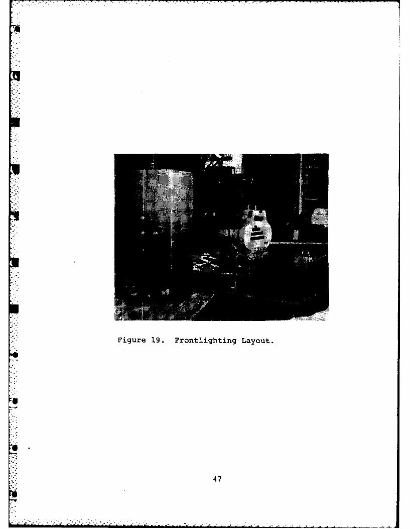
Figure 19. Frontlighting Layout.
47

0I.-
2 0U0
4 0J
0
'0'
z 448

Figure 21. Example of Backlighting Result UsingWGS-6A.
49

I
(a)
I'
(b)
Figure 22. Photo Sequence of Burning WGS-6A Strand
50
6"

2
(c)
I
(d)
51

- . - ~~~~~1
(e)
6
4.
52

Dwr = White lighting, brighto • ring diameter
Dwc = White lighting, darkcenter diameter
D - Df = Flame sheath diameter
'"I II I
- _ - Dbr Filtered lighting,bright ring diameter
bc Dbc - Filtered lighting,dark center diameter
*Figure 23. Object Diameter References.
53
..
4 4 *o 4 -.. . . . . . . .

w 6 0 0
Cr 0 REF 2<200A THIS REPORT
0r 0 20 40 60 s0
CID INITIAL PARTICLE DIAMETER(jam)
Figure 24. Burning Particle Diameter Versus Initial ParticleDiameter.
54

LIST OF REFERENCES
1. Price, E. W., Kraeutle, K. J., Prentice, J. L., Boggs,. L., Crump, J. E., and Zurn, D. E., Behavior ofAluminum in Solid Propellant Combustion, Naval WeaponsCenter, China Lake, CA., 1982.
2. DiLoreto, V. D., An Experimental Study of Solid PropellantDeflagration Using High Speed Motion Pictures and PostfireResidue Analysis, Engineer's Thesis, Naval PostgraduateSchool, Monterey, Ca., 1980.
3. Karagounis, S. G., An Investigation of Particulate Behaviorin Solid Rocket Motors, Engineer's Thesis, Naval Postgrad-uate School, Monterey, CA., 1980.
4. Boggs, T. L., Crump, J. E., Kraeutle, K. J., and Zurn,D. E., "Cinephotomicrography and Scanning Electron Micro-scopy as Used to Study Solid Propellant Combustion",Experimental Diagnostics in Combustion of Solids, AIAAProgress in Astronautics and Aeronautics, Vol. 63, 1978.
5. O'Shea, C. D., Callen, W. R., Rhodes, W. T., An Intro-duction to Lasers and Their Applications, Addison-Wesley
* - Publishing Company, Reading, Mass., 1978.
6. Kraeutle, K. J., "Particle Size Analysis in Solid Pro-pellant Combustion Research", Experimental Diagnosticsin Combustion of Solids, AIAA Progress in Astronauticsand Aeronautics, Vol. 63, 1978.
7. Kennedy, J. R., Optical Study of Ammonium-PerchlorateSandwiches with a Polybutadiene Acrylic Acid Binder,Naval Postgraduate School, Monterey, Ca., 1971.
8. Blaker, A. A., Photography for Scientific PublicationW. H. Freeman and Co., San Francisco, CA., 1965.
9. Hyzer, W. G., Engineering and Scientific High-SpeedPhotography, The MacMillan Co., New York, NY, 1962.
C 10. Netzer, D. W., and Andrews, J. R., "Schlieren Studiesof Solid-Propellant Combustion", Experimental Diagnos-tics in Combustion of Solids, AIAA Progress in Astro-nautics and Aeronautics, Vol. 63, 1978.
55
U

11. Andrews, J. R., and Netzer, D. W., The Development of anOptically Active Laser Schlieren System with Applicationto High Pressure Solid Propellant Combustion, Naval Post-graduate School, Monterey, CA., 1975.
12. Renie, J. P., Lilley, J. S., and Frederick, R. A., Jr.,Aluminum Particle Combustion in Composite Solid Propellants,Purdue University, West Lafayette, Ind., 1982.
13. Briones, R. A., and Wuerker, R. F., "Holography of SolidPropellant Combustion", Experimental Diagnostics inCombustion of Solids, AIAA, Progress in Astronauticsand Aeronautics, Vol. 63, 1978.
I56
.-
2 56
!,2

INITIAL DISTRIBUTION LIST
go. Copies
1. Defense Technical Information Center 2
Cameron StationAlexandria, Virginia 22314
2. Library, Code 0142 2
Naval Postgraduate SchoolMonterey, California 93940
3. Department Chairman, Code 67 1
Department of AeronauticsNaval Postgraduate SchoolMonterey, California 93940
4. Professor D. W. Netzer, Code 67 Nt 3
Department of AeronauticsNaval Postgraduate SchoolMonterey, California 93940
5. LCDR R. J. Edington 2
VF-101NAS OceanaVirginia Beach, Virginia 23460
'65
57

AtA


![UNITED STATES REPORTS · 522BV$ Unit: UIII [01-06-00 18:52:00] PGT: FRT JUSTICES of the SUPREME COURT during the time of these reports* WILLIAM H. REHNQUIST, Chief Justice. JOHN PAUL](https://static.fdocuments.us/doc/165x107/5be324ac09d3f24c478cfe90/united-states-reports-522bv-unit-uiii-01-06-00-185200-pgt-frt-justices.jpg)