UBC 7-2-97 positive - Versatrac - Interior Aluminum · PDF fileINTERIOR FRAMES TM 1-2...
99
INTERIOR FRAMES TM 1-1 VERSATRAC; Houston, Texas; 1-800-395-2014 Rev. 06/12 There is now an attractive and versatile alternative to old- fashioned pressed steel door frames. The Versatrac system accommodates itself to a wide range of job requirements for interior aluminum frames. You can specify a variety of opening sizes and types, and be assured of maintaining a uniform, clean appearance. Only Versatrac systems offer a complete set of features that ease installation and create a sturdier frame. And our door frames use integral hinge and strike reinforcements, for max- imum door hanging strength. Over 20 years of service in thousands of installations nationwide have proven the reliability of aluminum frame systems. They are easy to install, can be delivered quickly, and are competitive in price. Versatrac design advantages include: • The sharp, clean lines of extruded aluminum • Quick installation • Your choice of four standard finishes, plus custom finishes (at additional cost and lead time). All finishes are factory applied. • Fully concealed fasteners • Complete system to facilitate freedom of design • 20-minute fire rating • 90-minute fire rating • UBC 7-2-97 positive pressure Integral aluminum hinge reinforcements maximize door hanging strength on Versatrac frames. Versatrac door frames feature a stop which positively locks to the jamb. This feature ensures tight fit and maximum security. Versatrac door frames feature an integral strike which eliminates a separate strike box that must be installed on site. Cross section of glazing member Integral strike reinforcement Hinge reinforcement Cross section of snap-on door stop
Transcript of UBC 7-2-97 positive - Versatrac - Interior Aluminum · PDF fileINTERIOR FRAMES TM 1-2...
INTERIOR FRAMES
TM
1-1
VERSATRAC; Houston, Texas; 1-800-395-2014Rev. 06/12
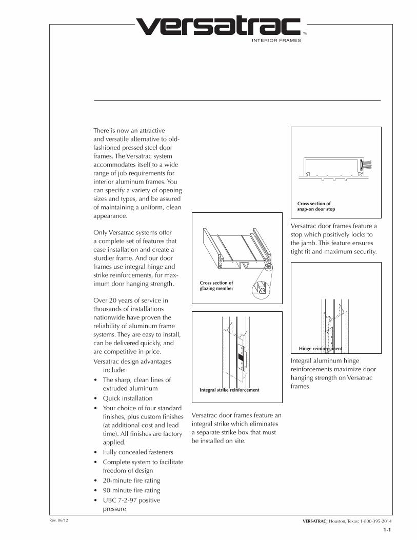
There is now an attractive and versatile alternative to old-fashioned pressed steel door frames. The Versatrac system accommodates itself to a wide range of job requirements for interior aluminum frames. You can specify a variety of opening sizes and types, and be assured of maintaining a uniform, clean appearance.
Only Versatrac systems offer a complete set of features that ease installation and create a sturdier frame. And our door frames use integral hinge and strike reinforcements, for max-imum door hanging strength.
Over 20 years of service in thousands of installations nationwide have proven the reliability of aluminum frame systems. They are easy to install, can be delivered quickly, and are competitive in price.
Versatrac design advantages include:
• Thesharp,cleanlinesof extruded aluminum
• Quickinstallation
• Yourchoiceoffourstandardfinishes, plus custom finishes (at additional cost and lead time). All finishes are factory applied.
• Fullyconcealedfasteners
• Completesystemtofacilitatefreedom of design
• 20-minutefirerating
• 90-minutefirerating
• UBC7-2-97positivepressure
Integral aluminum hinge reinforcements maximize door hanging strength on Versatrac frames.
Versatrac door frames feature a stop which positively locks to the jamb. This feature ensures tight fit and maximum security.
Versatrac door frames feature an integral strike which eliminates a separate strike box that must be installed on site.
Cross section of glazing member
Integral strike reinforcement
Hinge reinforcement
Cross section of snap-on door stop
INTERIOR FRAMES
TM
1-2
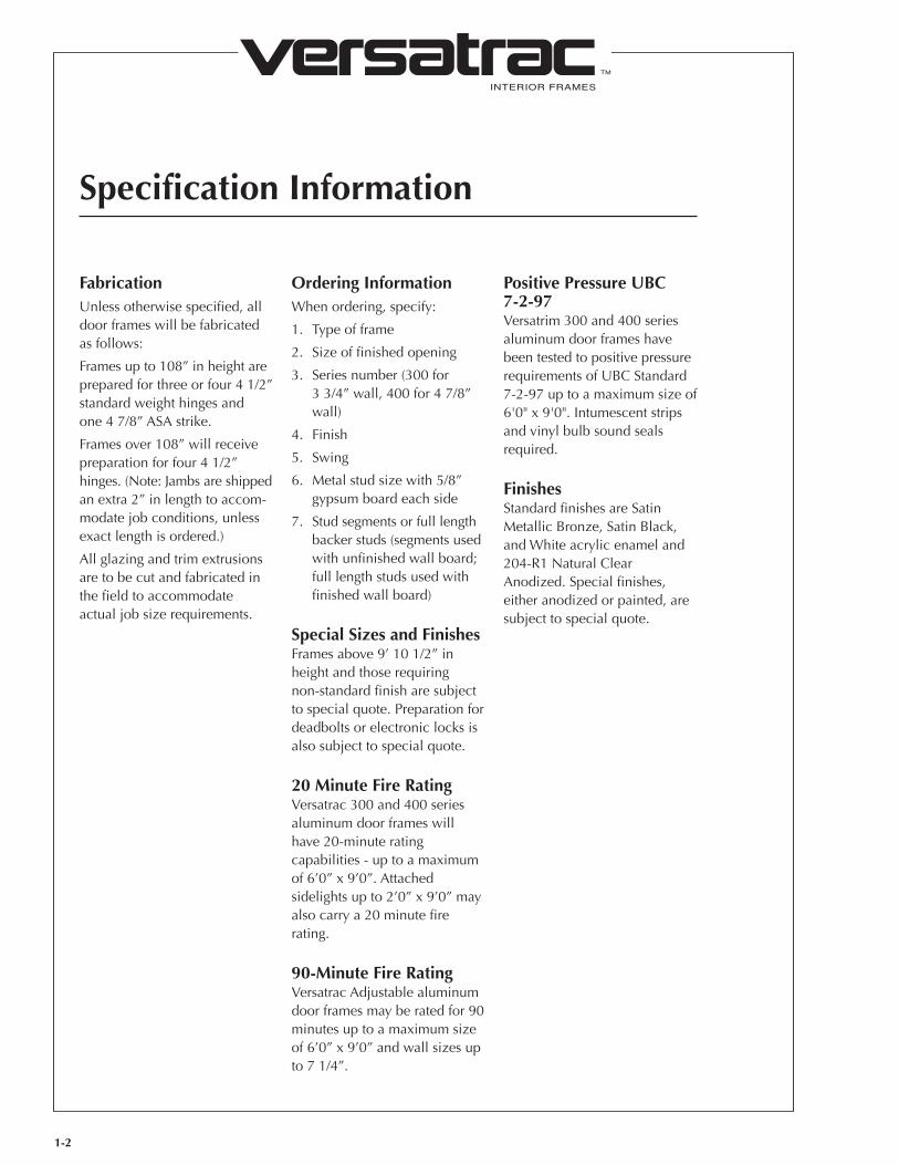
FabricationUnlessotherwisespecified,all door frames will be fabricated as follows:
Framesupto108”inheightarepreparedforthreeorfour41/2”standard weight hinges and one47/8”ASAstrike.
Framesover108”willreceivepreparationforfour41/2”hinges. (Note: Jambs are shipped anextra2”inlengthtoaccom-modate job conditions, unless exact length is ordered.)
All glazing and trim extrusions are to be cut and fabricated in the field to accommodate actual job size requirements.
Ordering InformationWhen ordering, specify:
1. Typeofframe
2. Sizeoffinishedopening
3. Seriesnumber(300for 33/4”wall,400for47/8”wall)
4. Finish
5. Swing
6. Metalstudsizewith5/8”gypsum board each side
7. Studsegmentsorfulllength backer studs (segments used with unfinished wall board; full length studs used with finished wall board)
Special Sizes and Finishes Framesabove9’101/2”in height and those requiring non-standard finish are subject to special quote. Preparation for deadbolts or electronic locks is also subject to special quote.
20 Minute Fire RatingVersatrac 300 and 400 series aluminum door frames will have 20-minute rating capabilities - up to a maximum of6’0”x9’0”.Attachedsidelightsupto2’0”x9’0”mayalso carry a 20 minute fire rating.
90-Minute Fire RatingVersatrac Adjustable aluminum doorframesmayberatedfor90minutes up to a maximum size of6’0”x9’0”andwallsizesupto71/4”.
Positive Pressure UBC 7-2-97Versatrim 300 and 400 series aluminum door frames have been tested to positive pressure requirementsofUBCStandard7-2-97uptoamaximumsizeof6'0"x9'0".Intumescentstripsand vinyl bulb sound seals required.
FinishesStandardfinishesareSatinMetallicBronze,SatinBlack,and White acrylic enamel and 204-R1NaturalClearAnodized.Specialfinishes,either anodized or painted, are subject to special quote.
Specification Information
INTERIOR FRAMES
TM
1-3
VERSATRAC; Houston, Texas; 1-800-395-2014Rev. 06/12
RCH Ceilingheight-designationfortoptrackframes or where jamb butts under side header member at sidelight jambs
RAF Freestanding-notattachedtotoptrackorwhere drywall is above frame
RAF1 FreestandingheaderRAF2 FreestandinghingejambRAF3FreestandingstrikejambRCH2CeilingheighthingejambRCH3CeilingheightstrikejambRCH4Ceilingheightsnap-inheaderLT Sidelite2LT Sidelitebothsidesofframe1/2LT Half sidelite, drywall below
STD Standardbackerstudfor5/8”gypsumboardQUICK MOUNT Attached segmented backer studsBASICShellofframeonly/designationusedwhen
full length backer studs are supplied separately for use with factory finished gypsum board, or when frame is backed with wood studs by others
EXACT LENGTH Jambs cut to nominal door heightEXTRA LENGTHJambssupplied2”oversize.
Furnishedstandardforfloortoceilingframesto accommodate floor variations
THROAT Wall thickness
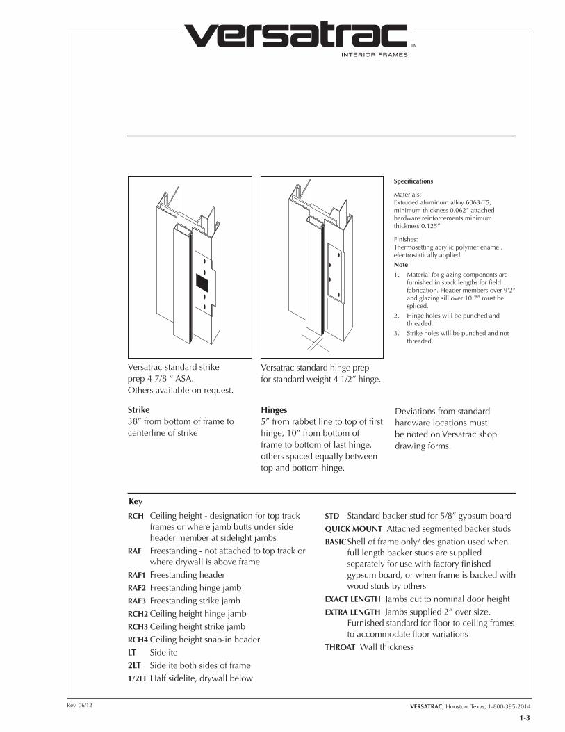
Versatrac standard strike prep47/8“ASA. Others available on request.
Versatrac standard hinge prep forstandardweight41/2”hinge.
Strike 38”frombottomofframetocenterline of strike
Hinges5”fromrabbetlinetotopoffirsthinge,10”frombottomofframe to bottom of last hinge, others spaced equally between top and bottom hinge.
Specifications
Materials:Extruded aluminum alloy 6063-T5, minimumthickness0.062”attachedhardware reinforcements minimum thickness0.125”
Finishes:Thermosetting acrylic polymer enamel, electrostatically applied
Note
1. Materialforglazingcomponentsarefurnished in stock lengths for field fabrication.Headermembersover9'2”andglazingsillover10'7”mustbespliced.
2. Hinge holes will be punched and threaded.
3. Strikeholeswillbepunchedandnotthreaded.
Key
Deviations from standard hardware locations must be noted on Versatrac shop drawing forms.
INTERIOR FRAMES
TM
VERSATRAC; Houston, Texas; 1-800-395-2014Rev. 06/12
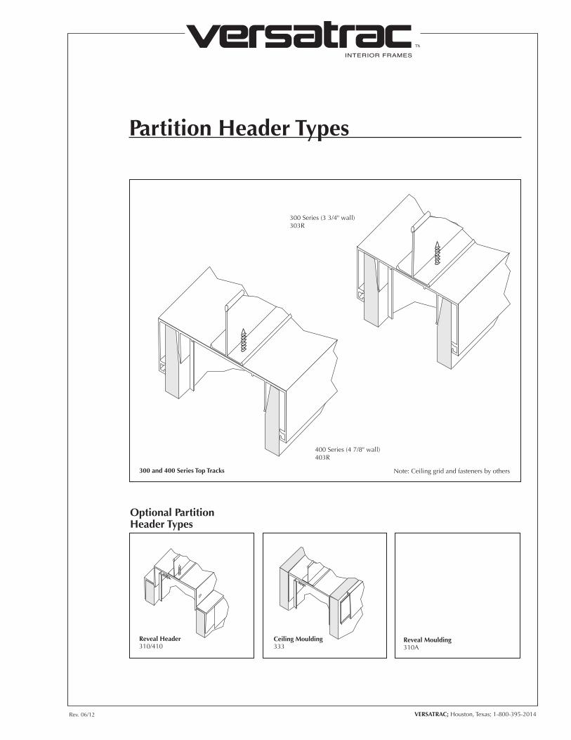
Partition Header Types
300 Series (3 3/4" wall)303R
400 Series (4 7/8" wall)403R
Note: Ceiling grid and fasteners by others
Reveal Header310/410
Ceiling Moulding333
Optional Partition Header Types
300 and 400 Series Top Tracks
Reveal Moulding310A

INTERIOR FRAMES
TM
VERSATRAC; Houston, Texas; 1-800-395-2014Rev. 06/12
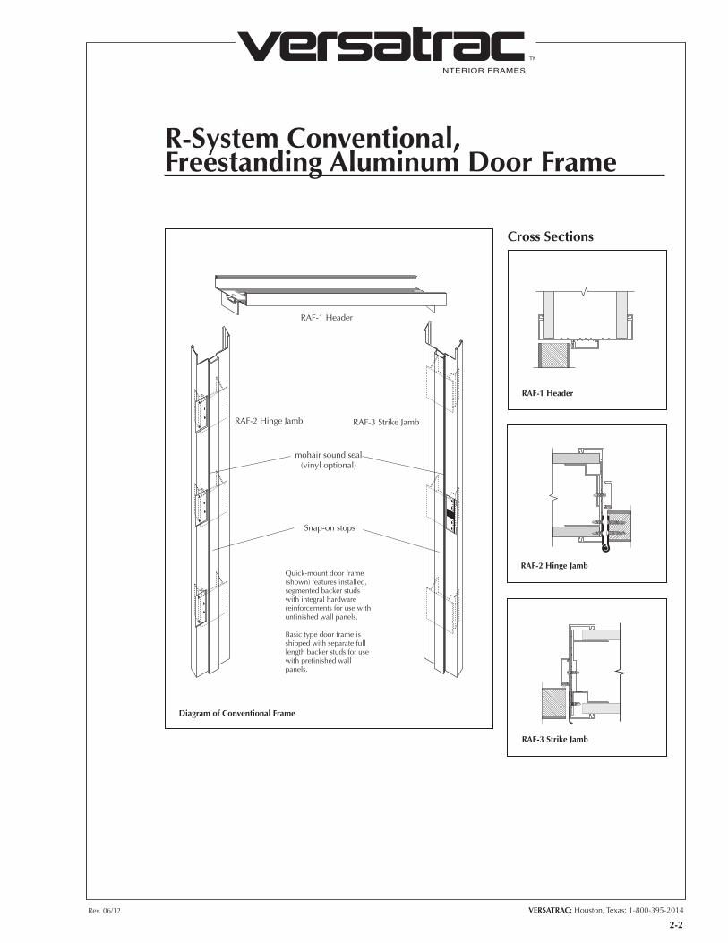
RAF-1 Header
RAF-2 Hinge Jamb RAF-3 Strike Jamb
mohair sound seal(vinyl optional)
Snap-on stops
Quick-mount door frame (shown) features installed, segmented backer studs with integral hardware reinforcements for use with unfinished wall panels.
Basic type door frame is shipped with separate full length backer studs for use with prefinished wall panels.
RAF-1 Header
RAF-2 Hinge Jamb
Cross Sections
Diagram of Conventional Frame
R-System Conventional,Freestanding Aluminum Door Frame
RAF-3 Strike Jamb
2-2

INTERIOR FRAMES
TM
Conventional, Freestanding Aluminum Door Frame with Sidelites
300 Series (for 3 3/4" walls) shown. 400 Series (for 4 7/8" walls) also available.
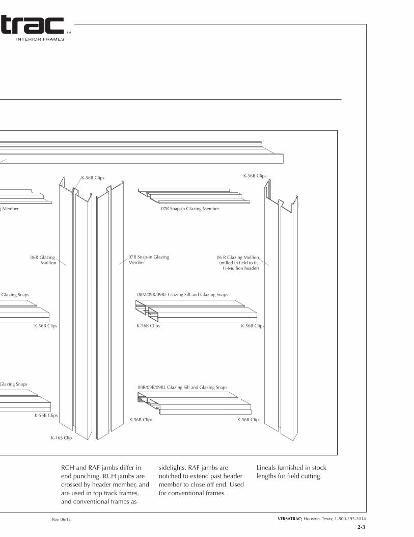
Lineals are specified by series number and part number. For example, a 300 Series glazing mullion would be part 306R.
RCH-4 Snap-in Header
RAF-2 Hinge Jamb
07R Snap-in GlazingMember
07R Snap-in Glazing Member
11R H-Mullion
07R Snap-in Glazing Member
08M/09R/09RL Glazing Sill and Glazing Snaps
08R/09R/09RL Glazing Sill and Glazing Snaps
08M/09R/09RL Glazing Sill and Glazing Snaps
K-10 Clip
K-16H Clip
mohair sound seal(vinyl optional)
CH-3/LT Door Jamb(prepared for strike plate)
Snap-on stops
07R Snap-in GlazingMember
06R Glazing Mullion
06 R Glazing Mullion(milled in field to fit
H-Mullion header)
08R/09R/09RL Glazing Sill and Glazing Snaps
K-56B Clips K-56B Clips
K-56B ClipsK-56B Clips
K-16S Clip K-16S Clip
K-56B Clips K-56B Clips
K-56B Clips K-56B Clips
K-56B Clips K-56B Clips
Rev. 06/12 VERSATRAC; Houston, Texas; 1-800-395-2014
INTERIOR FRAMES
TM
RCH and RAF jambs differ in end punching. RCH jambs are crossed by header member, and are used in top track frames, and conventional frames as
sidelights. RAF jambs are notched to extend past header member to close off end. Used for conventional frames.
Lineals furnished in stock lengths for field cutting.
RCH-4 Snap-in Header
RAF-2 Hinge Jamb
07R Snap-in GlazingMember
07R Snap-in Glazing Member
11R H-Mullion
07R Snap-in Glazing Member
08M/09R/09RL Glazing Sill and Glazing Snaps
08R/09R/09RL Glazing Sill and Glazing Snaps
08M/09R/09RL Glazing Sill and Glazing Snaps
K-10 Clip
K-16H Clip
mohair sound seal(vinyl optional)
CH-3/LT Door Jamb(prepared for strike plate)
Snap-on stops
07R Snap-in GlazingMember
06R Glazing Mullion
06 R Glazing Mullion(milled in field to fit
H-Mullion header)
08R/09R/09RL Glazing Sill and Glazing Snaps
K-56B Clips K-56B Clips
K-56B ClipsK-56B Clips
K-16S Clip K-16S Clip
K-56B Clips K-56B Clips
K-56B Clips K-56B Clips
K-56B Clips K-56B Clips
2-3

INTERIOR FRAMES
TM
VERSATRAC; Houston, Texas; 1-800-395-2014Rev. 06/12
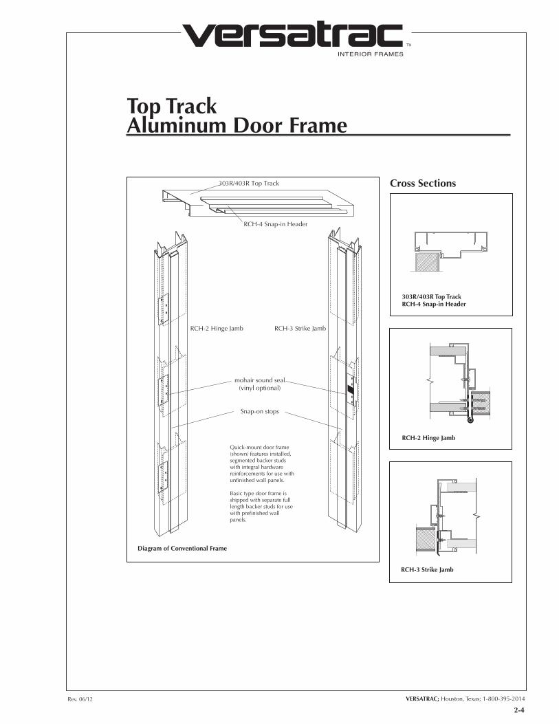
Top TrackAluminum Door Frame
RCH-4 Snap-in Header
RCH-2 Hinge Jamb RCH-3 Strike Jamb
303R/403R Top Track
mohair sound seal(vinyl optional)
Snap-on stops
Quick-mount door frame (shown) features installed, segmented backer studs with integral hardware reinforcements for use with unfinished wall panels.
Basic type door frame is shipped with separate full length backer studs for use with prefinished wall panels.
303R/403R Top Track RCH-4 Snap-in Header
RCH-2 Hinge Jamb
Cross Sections
Diagram of Conventional Frame
RCH-3 Strike Jamb
2-4
INTERIOR FRAMES
TM
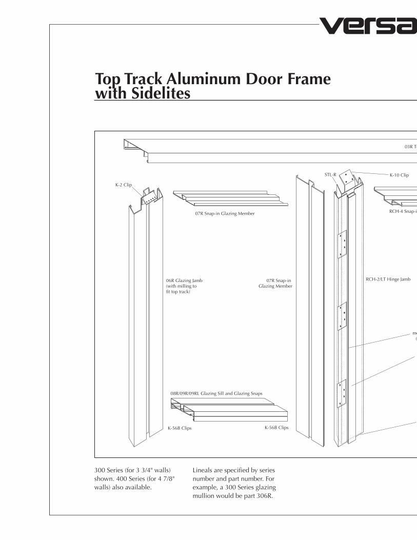
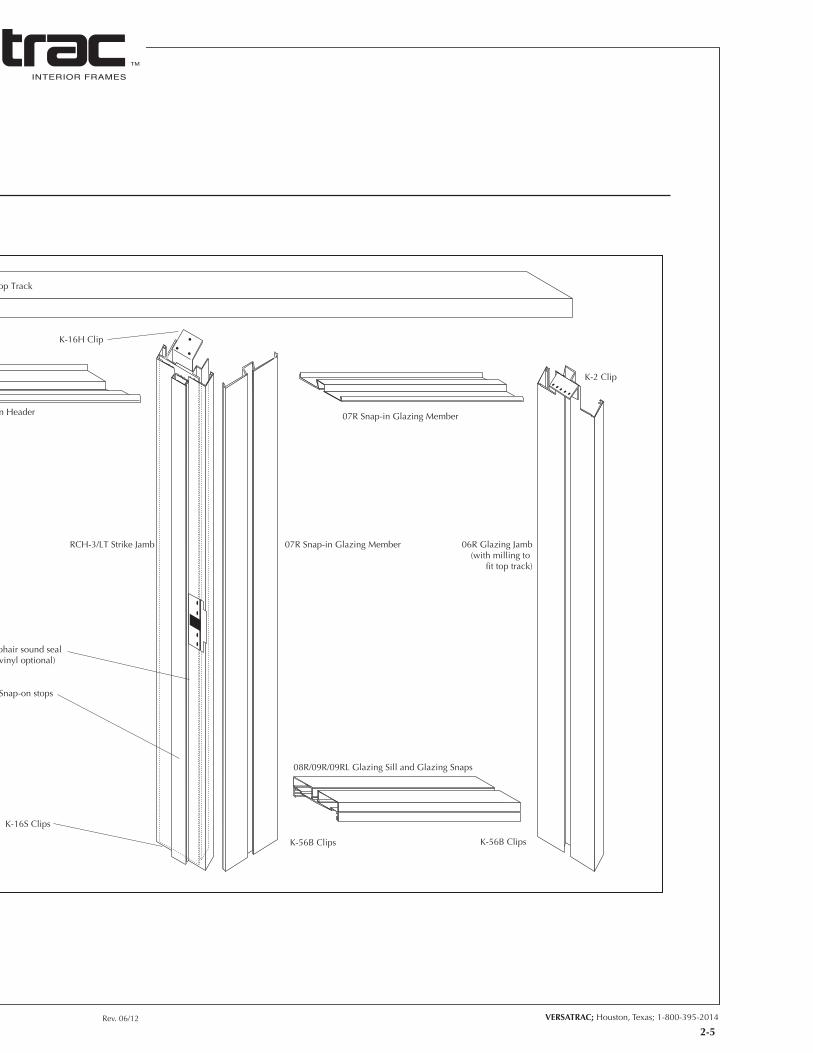
Top Track Aluminum Door Framewith Sidelites
300 Series (for 3 3/4" walls) shown. 400 Series (for 4 7/8" walls) also available.
Lineals are specified by series number and part number. For example, a 300 Series glazing mullion would be part 306R.
07R Snap-in Glazing Member 07R Snap-in Glazing Member
06R Glazing Jamb(with milling to fit top track)
08R/09R/09RL Glazing Sill and Glazing Snaps 08R/09R/09RL Glazing Sill and Glazing Snaps
07R Snap-in Glazing Member
K-2 Clip
mohair sound seal(vinyl optional)
Snap-on stops
K-10 Clip
RCH-4 Snap-in Header
RCH-2/LT Hinge Jamb RCH-3/LT Strike Jamb 07R Snap-in Glazing Member 06R Glazing Jamb(with milling to
fit top track)
K-2 Clip
03R Top Track
STL-R K-16H Clip
K-56B Clips K-56B ClipsK-16S Clips
K-56B Clips K-56B Clips
Rev. 06/12 VERSATRAC; Houston, Texas; 1-800-395-2014
INTERIOR FRAMES
TM
2-5
07R Snap-in Glazing Member 07R Snap-in Glazing Member
06R Glazing Jamb(with milling to fit top track)
08R/09R/09RL Glazing Sill and Glazing Snaps 08R/09R/09RL Glazing Sill and Glazing Snaps
07R Snap-in Glazing Member
K-2 Clip
mohair sound seal(vinyl optional)
Snap-on stops
K-10 Clip
RCH-4 Snap-in Header
RCH-2/LT Hinge Jamb RCH-3/LT Strike Jamb 07R Snap-in Glazing Member 06R Glazing Jamb(with milling to
fit top track)
K-2 Clip
03R Top Track
STL-R K-16H Clip
K-56B Clips K-56B ClipsK-16S Clips
K-56B Clips K-56B Clips

INTERIOR FRAMES
TM
VERSATRAC; Houston, Texas; 1-800-395-2014Rev. 06/12
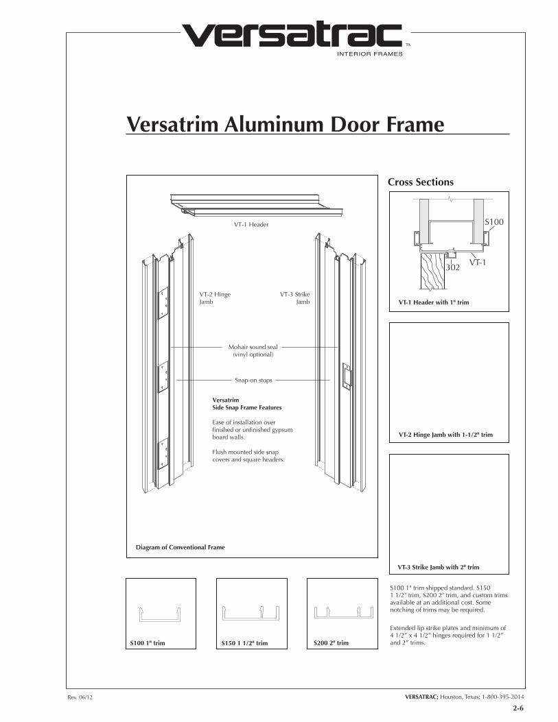
Versatrim Aluminum Door Frame
VT-1 Header
VT-2 HingeJamb
VT-3 StrikeJamb
Mohair sound seal(vinyl optional)
Snap-on stops
VersatrimSide Snap Frame Features
Ease of installation over finished or unfinished gypsum board walls.
Flush mounted side snap covers and square headers.
VT-1 Header with 1" trim
VT-2 Hinge Jamb with 1-1/2" trim
Cross Sections
Diagram of Conventional Frame
VT-3 Strike Jamb with 2" trim
S100 1" trim shipped standard. S150 1 1/2" trim, S200 2" trim, and custom trims available at an additional cost. Some notching of trims may be required.
Extended lip strike plates and minimum of 4 1/2” x 4 1/2” hinges required for 1 1/2” and 2” trims.S100 1" trim S150 1 1/2" trim S200 2" trim
2-6
S100
VT-1302

INTERIOR FRAMES
TM
3-1
VERSATRAC; Houston, Texas; 1-800-395-2014Rev. 06/12
Bifold, Bypass Pocket Door Units
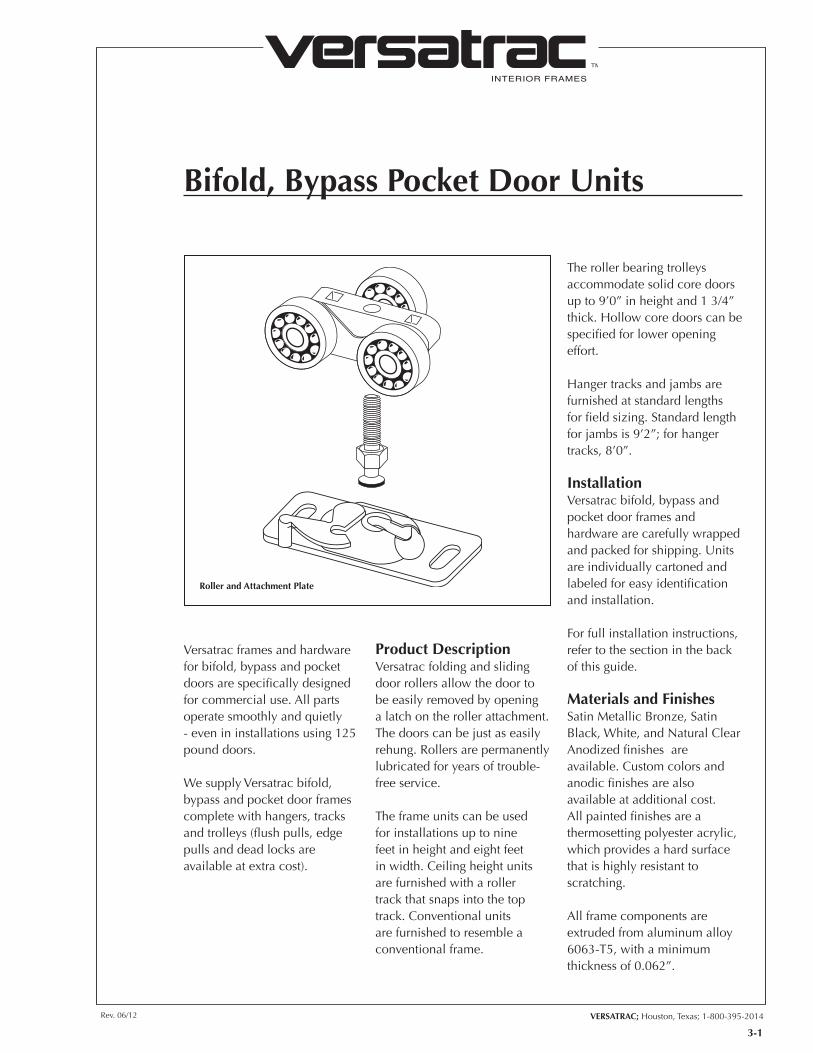
Roller and Attachment Plate
Versatrac frames and hardware for bifold, bypass and pocket doors are specifically designed for commercial use. All parts operate smoothly and quietly - even in installations using 125 pound doors.
We supply Versatrac bifold, bypass and pocket door frames complete with hangers, tracks and trolleys (flush pulls, edge pulls and dead locks are available at extra cost).
Product Description Versatrac folding and sliding door rollers allow the door to be easily removed by opening a latch on the roller attachment. The doors can be just as easily rehung. Rollers are permanently lubricated for years of trouble-free service.
The frame units can be used for installations up to nine feet in height and eight feet in width. Ceiling height units are furnished with a roller track that snaps into the top track. Conventional units are furnished to resemble a conventional frame.
The roller bearing trolleys accommodate solid core doors up to 9’0” in height and 1 3/4” thick. Hollow core doors can be specified for lower opening effort.
Hanger tracks and jambs are furnished at standard lengths for field sizing. Standard length for jambs is 9’2”; for hanger tracks, 8’0”.
Installation Versatrac bifold, bypass and pocket door frames and hardware are carefully wrapped and packed for shipping. Units are individually cartoned and labeled for easy identification and installation.
For full installation instructions, refer to the section in the back of this guide.
Materials and Finishes Satin Metallic Bronze, Satin Black, White, and Natural Clear Anodized finishes are available. Custom colors and anodic finishes are also available at additional cost. All painted finishes are a thermosetting polyester acrylic, which provides a hard surface that is highly resistant to scratching.
All frame components are extruded from aluminum alloy 6063-T5, with a minimum thickness of 0.062”.
INTERIOR FRAMES
TM
3-2
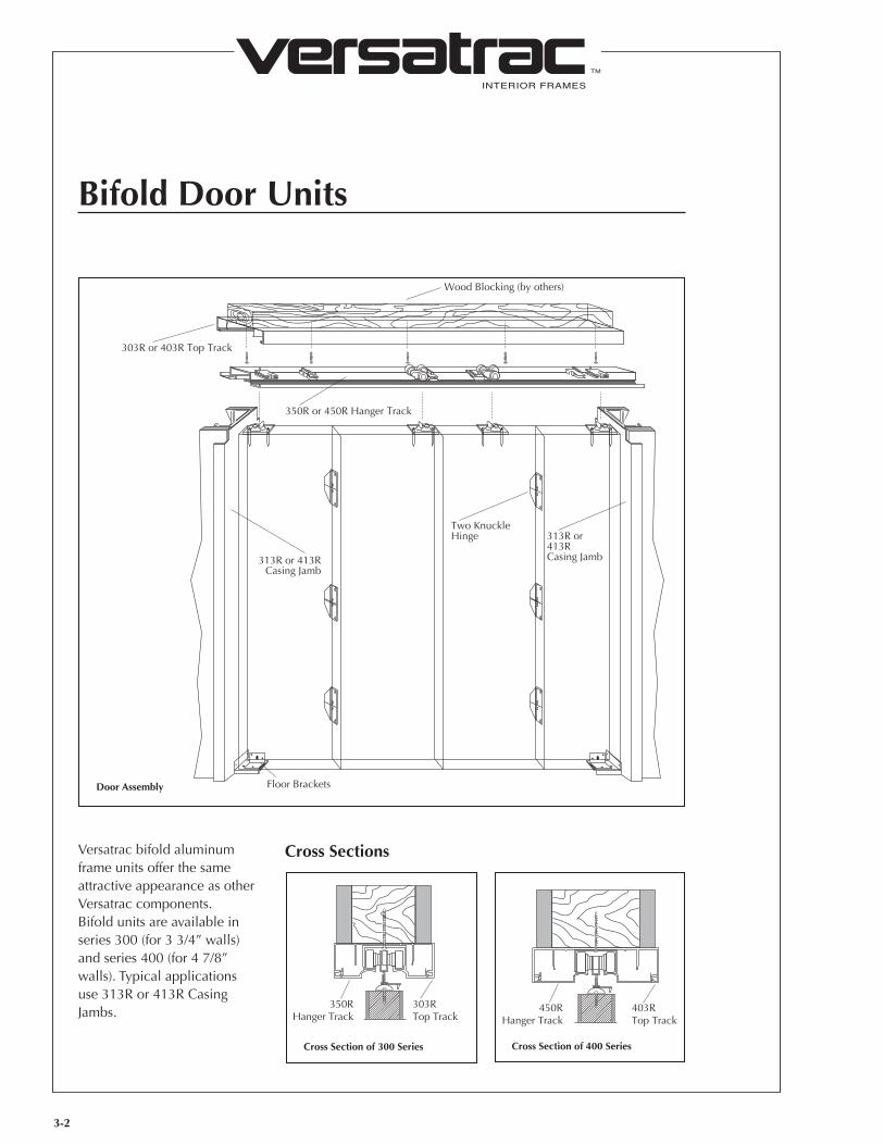
Bifold Door Units
Wood Blocking (by others)
350R or 450R Hanger Track
313R or413RCasing Jamb
Two KnuckleHinge
313R or 413RCasing Jamb
Floor Brackets
303R or 403R Top Track
Door Assembly
Versatrac bifold aluminum frame units offer the same attractive appearance as other Versatrac components. Bifold units are available in series 300 (for 3 3/4” walls) and series 400 (for 4 7/8” walls). Typical applications use 313R or 413R Casing Jambs.
Cross Sections
303RTop Track
350RHanger Track
Cross Section of 300 Series
403RTop Track
450RHanger Track
Cross Section of 400 Series
INTERIOR FRAMES
TM
3-3
VERSATRAC; Houston, Texas; 1-800-395-2014Rev. 06/12
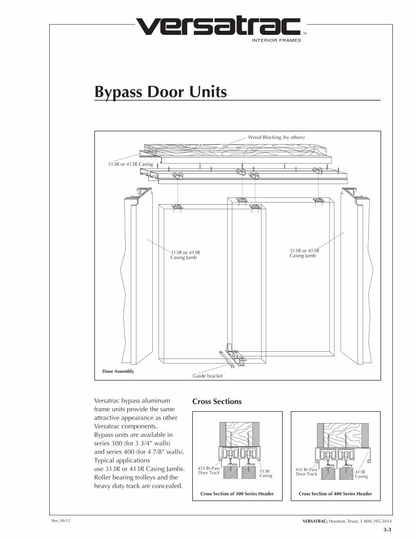
Wood Blocking (by others)
313R or 413R Casing
Guide bracket
313R or 413RCasing Jamb
313R or 413RCasing Jamb
Door Assembly
Cross Sections
313RCasing
455 Bi-PassDoor Track
Versatrac bypass aluminum frame units provide the same attractive appearance as other Versatrac components. Bypass units are available in series 300 (for 3 3/4” walls) and series 400 (for 4 7/8” walls). Typical applications use 313R or 413R Casing Jambs. Roller bearing trolleys and the heavy duty track are concealed.
Bypass Door Units
413RCasing
455 Bi-PassDoor Track
Cross Section of 300 Series Header Cross Section of 400 Series Header
INTERIOR FRAMES
TM
3-4
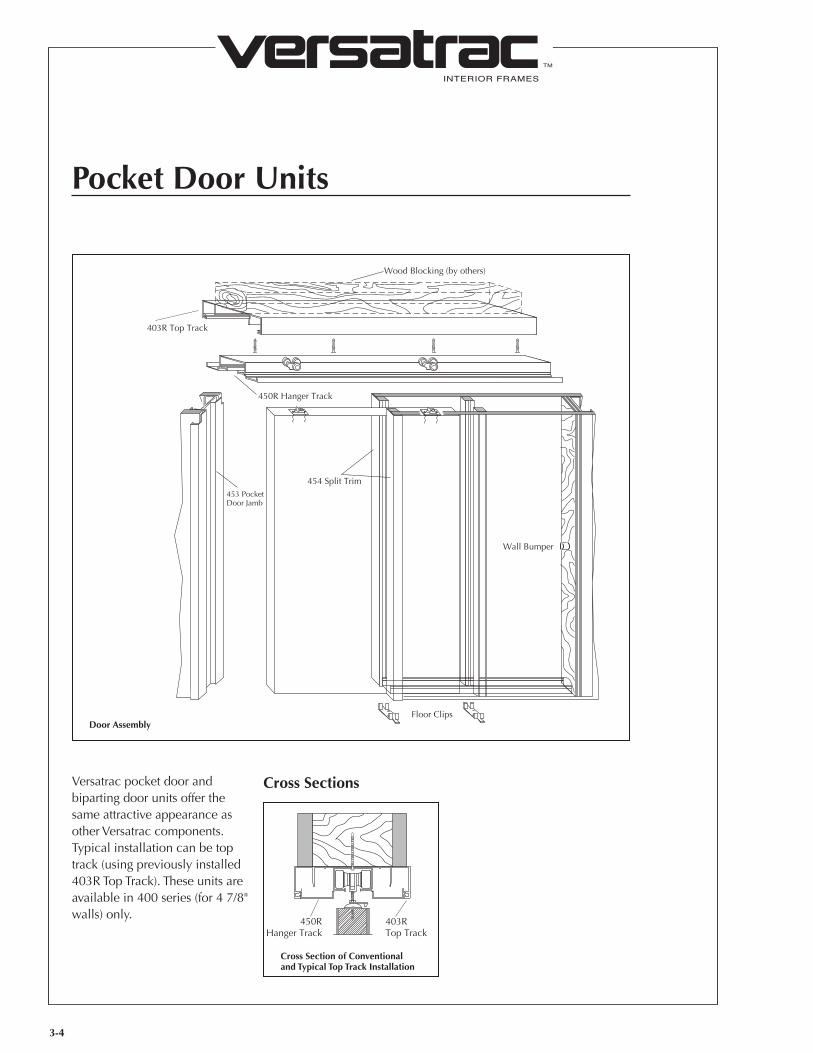
Pocket Door Units
Wood Blocking (by others)
450R Hanger Track
453 Pocket Door Jamb
454 Split Trim
Wall Bumper
Floor Clips
403R Top Track
Door Assembly
Versatrac pocket door and biparting door units offer the same attractive appearance as other Versatrac components. Typical installation can be top track (using previously installed 403R Top Track). These units are available in 400 series (for 4 7/8" walls) only.
Cross Sections
403RTop Track
450RHanger Track
Cross Section of Conventional and Typical Top Track Installation
4-1
INTERIOR FRAMES
TM
VERSATRAC; Houston, Texas; 1-800-395-2014Rev. 06/12 Rev. 01/01
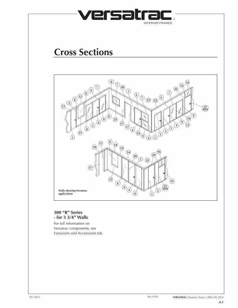
Cross Sections
1817 8
1419
1420
5
2016
25
218
49
821
17
821
1
54
98
2117
174
129
8 13
21
49
11
108
25SIM
1416
257
623
76
1
78
76
815
82
13
28
25SIM
22
22
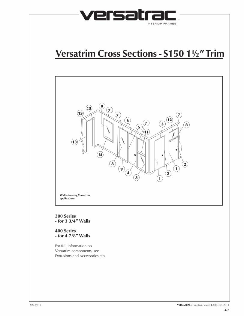
For full information on Versatrac components, see Extrusions and Accessories tab.
300 “R” Series - for 3 3/4” Walls
Walls showing Versatrac applications
INTERIOR FRAMES
TM
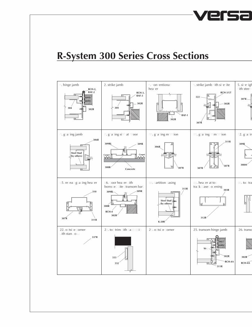
R-System 300 Series Cross Sections
25. transom hinge jamb 26. transom strike jamb
�. hinge jamb 2. strike jamb �. �on�entiona�hea�er
�. strike jamb �ith si�e�ite 5. si�e�ight hinge jamb �ith stee� st��
6. �on�entiona� hea�er�as �se� �ith si�e�ite�
�. �on�entiona� g�a�inghea�er
2�. �o�b�e hinge jamb
�. g�a�ing jamb �. g�a�ing si�� at ��oor ��. g�a�ing m���ion ��. g�a�ing ��m���ion �2. g�a�ing m���ion ��sna� ��. re�ea� �oor hea�er ��. g�a�ing to� tra�k
�5. re�ea� g�a�ing hea�er �6. �oor hea�er �ith borro�e� �ite �transom bar�
��. �artition �asing ��. hea�er at to�tra�k��ase� o�ening
��. to� tra�k��r��a�� hea�er 2�. to� tra�k �oor hea�er 2�. g�a�ing si�� at �a��
��. hinge jamb against �a��
22. o�tsi�e �orner �ith stan� o��
2�. to� trim �ith �a�� ��i� 2�. o�tsi�e �orner
304 302R
RCH-2,RAF-2 RCH-3,
RAF-3
RAF-1
RCH-3/LT
306R
310
RCH-4
302R
308R
309RL 309R
311R307R
337R
333
332
306R309R309RL
308RConcrete
CarpetCarpet
307R
307R
RCH-4A
302R
311R
309RL309R 310303R
RCH-4A
W-4
302R 302R
RAF-2RCH-2
K-20R
312R
313R 303R 303R303R
RCH-4
304
302R
302R
302R
307R
322
RCH-4
302R
311R Steel Stud(by others)
311R
307R307R
311R
308M 307RRAF-1
307R
Steel Stud(by others)
Steel Stud(by others)
302R
STL-3RRCH-2�307R
RCH-4A
302R
311R
Steel Stud(by others)
309R309RL
308R
W-�
W-�
2�. �on�entiona� hea�er at �ase� o�ening
311R
312R
2�. hinge jamb at �rame ��si�e�ight an� g�ass transom
RCH-4A
302R
311R
W-�
307R
302R
W-4 RAF-2
��. �� g�a�ing base at ��oor

Rev. 06/12 VERSATRAC; Houston, Texas; 1-800-395-2014
INTERIOR FRAMES
TM
4-2
25. transom hinge jamb 26. transom strike jamb
�. hinge jamb 2. strike jamb �. �on�entiona�hea�er
�. strike jamb �ith si�e�ite 5. si�e�ight hinge jamb �ith stee� st��
6. �on�entiona� hea�er�as �se� �ith si�e�ite�
�. �on�entiona� g�a�inghea�er
2�. �o�b�e hinge jamb
�. g�a�ing jamb �. g�a�ing si�� at ��oor ��. g�a�ing m���ion ��. g�a�ing ��m���ion �2. g�a�ing m���ion ��sna� ��. re�ea� �oor hea�er ��. g�a�ing to� tra�k
�5. re�ea� g�a�ing hea�er �6. �oor hea�er �ith borro�e� �ite �transom bar�
��. �artition �asing ��. hea�er at to�tra�k��ase� o�ening
��. to� tra�k��r��a�� hea�er 2�. to� tra�k �oor hea�er 2�. g�a�ing si�� at �a��
��. hinge jamb against �a��
22. o�tsi�e �orner �ith stan� o��
2�. to� trim �ith �a�� ��i� 2�. o�tsi�e �orner
304 302R
RCH-2,RAF-2 RCH-3,
RAF-3
RAF-1
RCH-3/LT
306R
310
RCH-4
302R
308R
309RL 309R
311R307R
337R
333
332
306R309R309RL
308RConcrete
CarpetCarpet
307R
307R
RCH-4A
302R
311R
309RL309R 310303R
RCH-4A
W-4
302R 302R
RAF-2RCH-2
K-20R
312R
313R 303R 303R303R
RCH-4
304
302R
302R
302R
307R
322
RCH-4
302R
311R Steel Stud(by others)
311R
307R307R
311R
308M 307RRAF-1
307R
Steel Stud(by others)
Steel Stud(by others)
302R
STL-3RRCH-2�307R
RCH-4A
302R
311R
Steel Stud(by others)
309R309RL
308R
W-�
W-�
2�. �on�entiona� hea�er at �ase� o�ening
311R
312R
2�. hinge jamb at �rame ��si�e�ight an� g�ass transom
RCH-4A
302R
311R
W-�
307R
302R
W-4 RAF-2
��. �� g�a�ing base at ��oor
4-3
INTERIOR FRAMES
TM
VERSATRAC; Houston, Texas; 1-800-395-2014Rev. 06/12
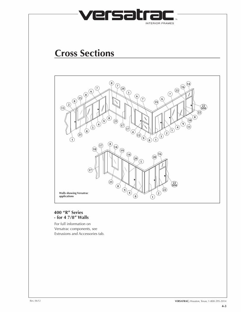
Cross Sections
For full information on Versatrac components, see Extrusions and Accessories tab.
400 “R” Series - for 4 7/8” Walls
1817 8
1419
1420
5
2016
222
184
98
21
17
821
1
54
98
2117
174
129
8 13
21
49
11
108
22SIM
1416
237
619
76
1
78
76
815
82
13
24
22
22SIM
Walls showing Versatrac applications
INTERIOR FRAMES
TM
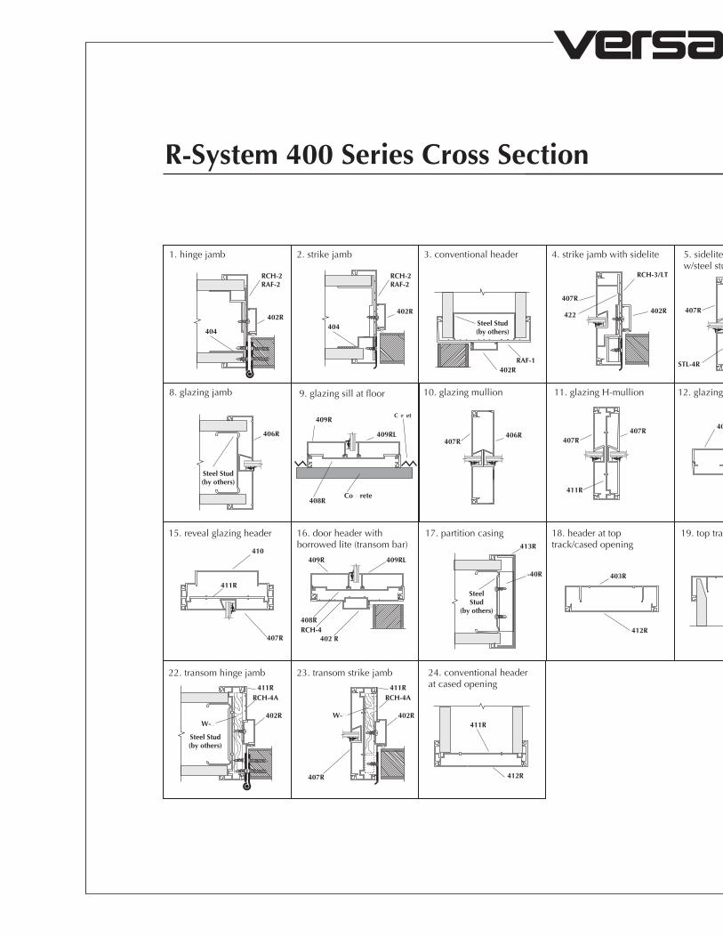
R-System 400 Series Cross Section
1. hinge jamb 2. strike jamb 3. conventional header 4. strike jamb with sidelite 6. conventional header(as used with sidelite)
7. conventional glazingheader
8. glazing jamb 9. glazing sill at floor 10. glazing mullion 11. glazing H-mullion 12. glazing mullion w/snap 13. reveal door header 14. glazing top track
25. double hinge jamb
15. reveal glazing header 16. door header with borrowed lite (transom bar)
22. transom hinge jamb 23. transom strike jamb
17. partition casing 18. header at top track/cased opening
19. top track/drywall header 20. top track door header
5. sidelite hinge jamb w/steel stud
26. hinge jamb against wall
404404
RCH-2RAF-2
RCH-2RAF-2
RAF-1
RCH-3/LT
Steel Stud(by others)
Steel Stud(by others)
410
Steel Stud(by others)402R
406R 409RL 407R 409RL
410
403R
RCH-2B
402R402R
RCH-4A W-4
411R
RCH-4407R
409R
408M
407R
411R
409R
408R
409RL
SteelStud
(by others)
413R
403R403R 403R
RCH-4
RCH-2
RAF-2BRCH-2B
402R
402R
W-4
STL-4R
407R
412R
�-40R
409R
408RRCH-4
402 R407R
402R
RCH-4A411R
402R
407R
RCH-4A411R
411R
402R
402R
402R
RCH-4 407R
411R
411R
407R
422
Steel Stud(by others)
Co��rete
C�r�et
21. �lazing sill at drywall
W-�W-�
24. conventional headerat cased opening
412R
411R
409RL409R
SteelStud
(by others)
408R
27. 4� glazing base at floor
406R407R

Rev. 06/12 VERSATRAC; Houston, Texas; 1-800-395-2014
INTERIOR FRAMES
TM
4-4
1. hinge jamb 2. strike jamb 3. conventional header 4. strike jamb with sidelite 6. conventional header(as used with sidelite)
7. conventional glazingheader
8. glazing jamb 9. glazing sill at floor 10. glazing mullion 11. glazing H-mullion 12. glazing mullion w/snap 13. reveal door header 14. glazing top track
25. double hinge jamb
15. reveal glazing header 16. door header with borrowed lite (transom bar)
22. transom hinge jamb 23. transom strike jamb
17. partition casing 18. header at top track/cased opening
19. top track/drywall header 20. top track door header
5. sidelite hinge jamb w/steel stud
26. hinge jamb against wall
404404
RCH-2RAF-2
RCH-2RAF-2
RAF-1
RCH-3/LT
Steel Stud(by others)
Steel Stud(by others)
410
Steel Stud(by others)402R
406R 409RL 407R 409RL
410
403R
RCH-2B
402R402R
RCH-4A W-4
411R
RCH-4407R
409R
408M
407R
411R
409R
408R
409RL
SteelStud
(by others)
413R
403R403R 403R
RCH-4
RCH-2
RAF-2BRCH-2B
402R
402R
W-4
STL-4R
407R
412R
�-40R
409R
408RRCH-4
402 R407R
402R
RCH-4A411R
402R
407R
RCH-4A411R
411R
402R
402R
402R
RCH-4 407R
411R
411R
407R
422
Steel Stud(by others)
Co��rete
C�r�et
21. �lazing sill at drywall
W-�W-�
24. conventional headerat cased opening
412R
411R
409RL409R
SteelStud
(by others)
408R
27. 4� glazing base at floor
406R407R

4-5
INTERIOR FRAMES
TM
VERSATRAC; Houston, Texas; 1-800-395-2014Rev. 06/12
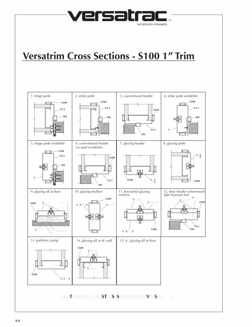
Versatrim Cross Sections - S100 1” Trim
300 Series - for 3 3/4” Walls
400 Series - for 4 7/8” Walls
For full information on Versatrim components, see Extrusions and Accessories tab.
1313 8
7
6
53
712
184
98
13
11
14
7
7
21
21
8
Walls showing Versatrim applications
4-6
INTERIOR FRAMES
TM
Versatrim Cross Sections - S100 1” Trim
302
VT-2 VT-3
VT-1
S100 S100
302
VT-3
3������
S100
302
302
1. hinge jamb
5. hinge jamb w/sidelite
9. glazing sill at floor
13. partition casing
10. glazing mullion 11. horizontal glazing mullion
12. door header w/borrowedlight (transom bar)
2. strike jamb 3. conventional header
VT-1 3��S����S
S100
302
3������ ������S100
6. conventional header(as used w/sidelite)
7. glazing header 8. glazing jamb
4. strike jamb w/sidelite
VT-2
3������
S100
302
3��S����S
S100
���������
��������
S100VT-1
3������
3��S����S3������
3��S����S
302
S1003��������3������
S100 3������
3�3���3
S100
S100
S100
3��������
14. glazing sill at drwall
3������
3������S100
15. 4 glazing sill at floor
�� T������� ����ST��S�S�����������V��S�� �
4-7
INTERIOR FRAMES
TM
VERSATRAC; Houston, Texas; 1-800-395-2014Rev. 06/12
Versatrim Cross Sections - S150 1½” Trim
300 Series - for 3 3/4” Walls
400 Series - for 4 7/8” Walls
For full information on Versatrim components, see Extrusions and Accessories tab.
1313 8
7
6
53
712
184
98
13
11
14
7
7
21
21
8
Walls showing Versatrim applications
4-8
INTERIOR FRAMES
TM
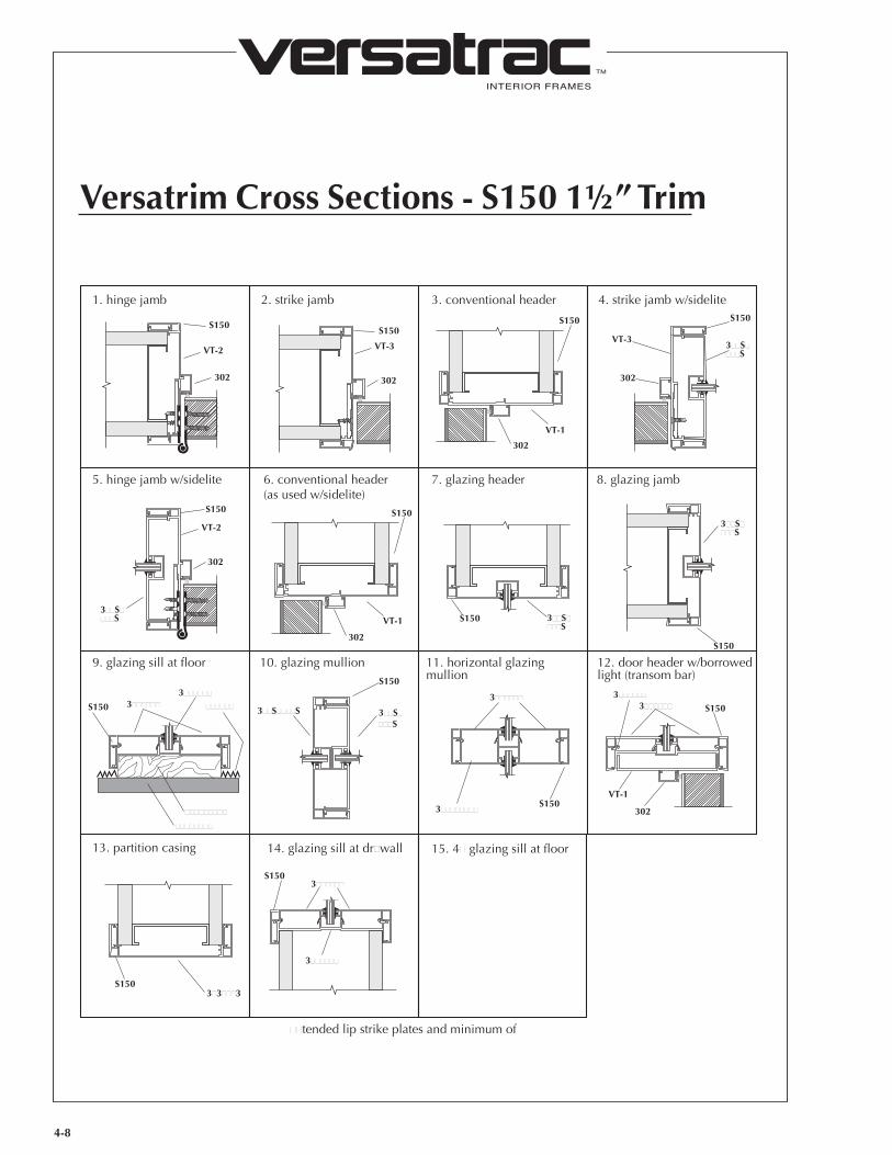
Versatrim Cross Sections - S150 1½” Trim
302
VT-2 VT-3
VT-1
S150
302
VT-33��S����S
S150
302
302
1. hinge jamb
5. hinge jamb w/sidelite
9. glazing sill at floor
13. partition casing
10. glazing mullion 11. horizontal glazing mullion
12. door header w/borrowedlight (transom bar)
2. strike jamb 3. conventional header
VT-1 3��S����S
S150
302
3������ ������S150
6. conventional header(as used w/sidelite)
7. glazing header 8. glazing jamb
4. strike jamb w/sidelite
VT-2
3��S����S
S150
302
3��S����S
S150
���������
��������
S150
3������3������
3��������
3������
3��S����S
302
S1503������
3��S����S
S150
3�3���3S150
S150S150
S150
VT-1
14. glazing sill at drwall
3������
3������S150
tended lip strike plates and minimum of 4 4 hinges reuired for 1 and 2 trims.
15. 4 glazing sill at floor
�� T������� ����ST��S�S�����������V��S�� �

4-9
INTERIOR FRAMES
TM
VERSATRAC; Houston, Texas; 1-800-395-2014Rev. 06/12
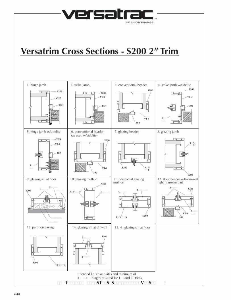
Versatrim Cross Sections - S200 2” Trim
300 Series - for 3 3/4” Walls
400 Series - for 4 7/8” Walls
For full information on Versatrim components, see Extrusions and Accessories tab.
1313 8
7
6
53
712
184
98
13
11
14
7
7
21
21
8
Walls showing Versatrim applications
4-10
INTERIOR FRAMES
TM
Versatrim Cross Sections - S200 2” Trim
302
VT-2 VT-3
VT-1
S200
302
VT-3
3������
S200
302
302
1. hinge jamb
5. hinge jamb w/sidelite
9. glazing sill at floor
13. partition casing
10. glazing mullion 11. horizontal glazing mullion
12. door header w/borrowedlight (transom bar)
2. strike jamb 3. conventional header
VT-1 3��S����S
S200
302
3������ ������S200
6. conventional header(as used w/sidelite)
7. glazing header 8. glazing jamb
4. strike jamb w/sidelite
VT-2
3������
S200
302
3��S����S
S200
���������
��������
S200
3��������
3������
3��S����S
3������
3��S����S
302
S2003��������3������
S200
3������
3�3���3S200
S200S200
S200
VT-1
14. glazing sill at drwall
3������
3������ S200
tended lip strike plates and minimum of 4 4 hinges reuired for 1 and 2 trims.
15. 4 glazing sill at floor
�� T������� ����ST��S�S�����������V��S�� �
4-11
INTERIOR FRAMES
TM
VERSATRAC; Houston, Texas; 1-800-395-2014Rev. 06/12
4-11
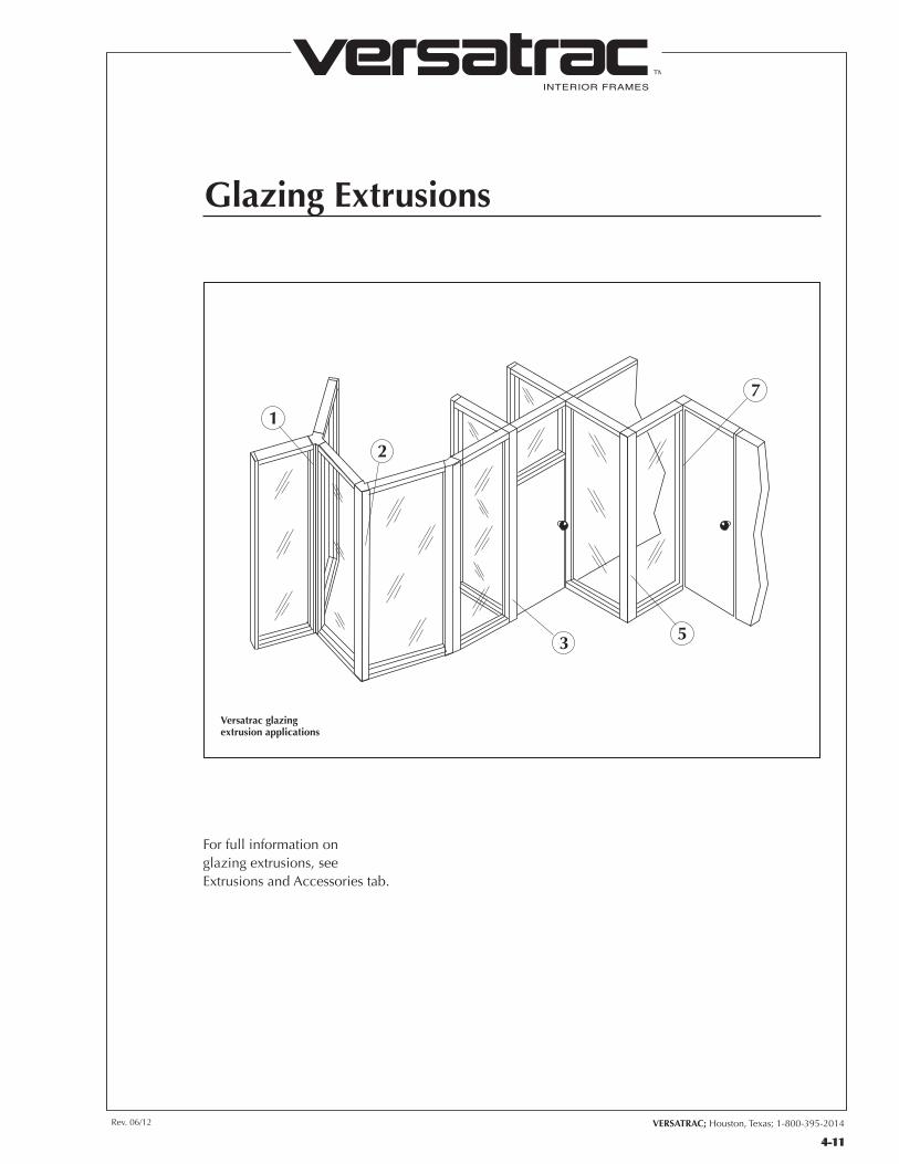
Glazing Extrusions
1
2
3 5
7
For full information on glazing extrusions, see Extrusions and Accessories tab.
300 “R” Series - for 3 3/4” Walls
Versatrac glazing extrusion applications
INTERIOR FRAMES
TM
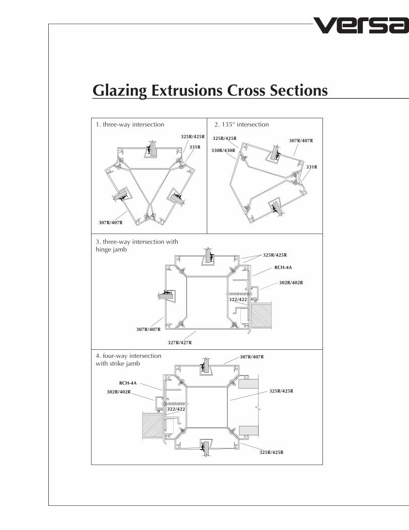
Glazing Extrusions Cross Sections
1. three-way intersection 2. 135° intersection
4. four-way intersection with strike jamb
3. three-way intersection withhinge jamb
307R/407R
307R/407R
307R/407R
325R/425R
302R/402R
RCH-4A
325R/425R
327R/427R
331R
331R
325R/425R307R/407R325R/425R
325R/425R
302R/402R
RCH-4A
330R/430R
322/422
322/422
Rev. 06/12 VERSATRAC; Houston, Texas; 1-800-395-2014
INTERIOR FRAMES
TM
4-12
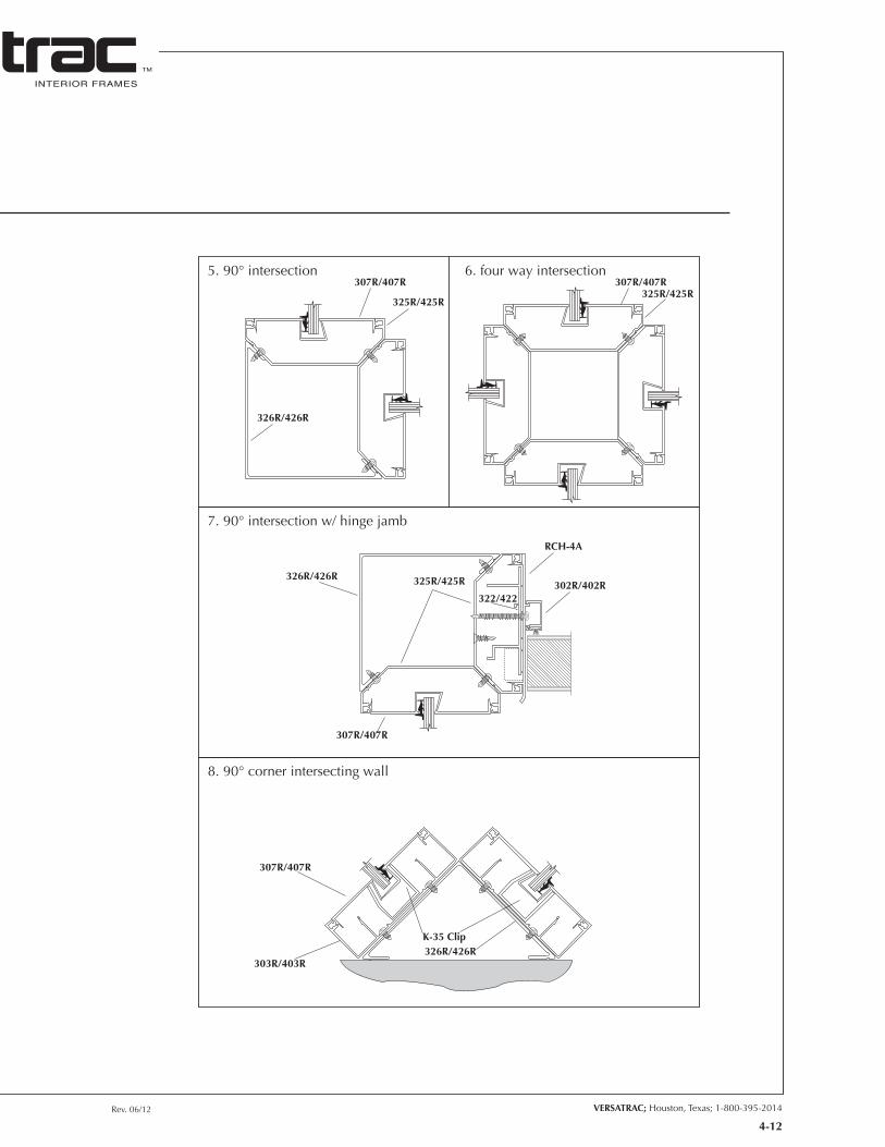
5. 90° intersection 6. four way intersection
7. 90° intersection w/ hinge jamb
8. 90° corner intersecting wall
307R/407R
325R/425R
307R/407R325R/425R
307R/407R
307R/407R
326R/426RK-35 Clip
303R/403R
RCH-4A
302R/402R325R/425R326R/426R
326R/426R
322/422
INTERIOR FRAMES
TM
VERSATRAC; Houston, Texas; 1-800-395-2014Rev. 06/12
5-1
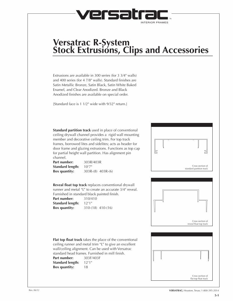
Extrusions are available in 300 series (for 3 3/4" walls) and 400 series (for 4 7/8" walls). Standard finishes are Satin Metallic Bronze, Satin Black, Satin White Baked Enamel, and Clear Anodized. Bronze and Black Anodized finishes are available on special order.
[Standard face is 1 1/2" wide with 9/32" return.]
Reveal float top track replaces conventional drywall runner and metal “L” to create an accurate 3/4" reveal. Furnished in standard black painted finish. Part number: 310/410 Standard length: 12'1"Box quantity: 310-(18) 410-(16)
Flat top float track takes the place of the conventional ceiling runner and metal trim “L” to give an excellent wall/ceiling alignment. Can be used with Versatrac standard head frames. Furnished in mill finish.Part number: 303F/403FStandard length: 12'1"Box quantity: 18
Standard partition track used in place of conventional ceiling drywall channel provides a rigid wall mounting member and decorative ceiling trim. For top track frames, borrowed lites and sidelites; acts as header for door frame and glazing extrusions. Functions as top cap for partial height wall partition. Has alignment pin channel.Part number: 303R/403RStandard length: 10'7"Box quantity: 303R-(8) 403R-(6)
Versatrac R-SystemStock Extrusions, Clips and Accessories
Cross section of standard partition track
Cross section of reveal float top track
Cross section of flat top float track
INTERIOR FRAMES
TM
5-2
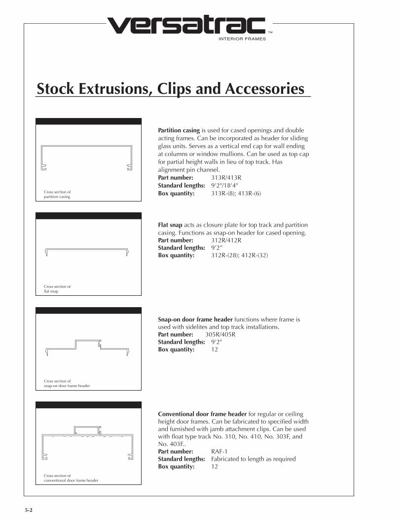
Partition casing is used for cased openings and double acting frames. Can be incorporated as header for sliding glass units. Serves as a vertical end cap for wall ending at columns or window mullions. Can be used as top cap for partial height walls in lieu of top track. Has alignment pin channel.Part number: 313R/413RStandard lengths: 9'2"/18'4"Box quantity: 313R-(8); 413R-(6)
Flat snap acts as closure plate for top track and partition casing. Functions as snap-on header for cased opening.Part number: 312R/412RStandard lengths: 9’2”Box quantity: 312R-(28); 412R-(32)
Snap-on door frame header functions where frame is used with sidelites and top track installations. Part number: 305R/405RStandard lengths: 9'2"Box quantity: 12
Conventional door frame header for regular or ceiling height door frames. Can be fabricated to specified width and furnished with jamb attachment clips. Can be used with float type track No. 310, No. 410, No. 303F, and No. 403F..Part number: RAF-1Standard lengths: Fabricated to length as requiredBox quantity: 12
Stock Extrusions, Clips and Accessories
Cross section of partition casing
Cross section of flat snap
Cross section of snap-on door frame header
Cross section of conventional door frame header
INTERIOR FRAMES
TM
VERSATRAC; Houston, Texas; 1-800-395-2014Rev. 06/12
5-3
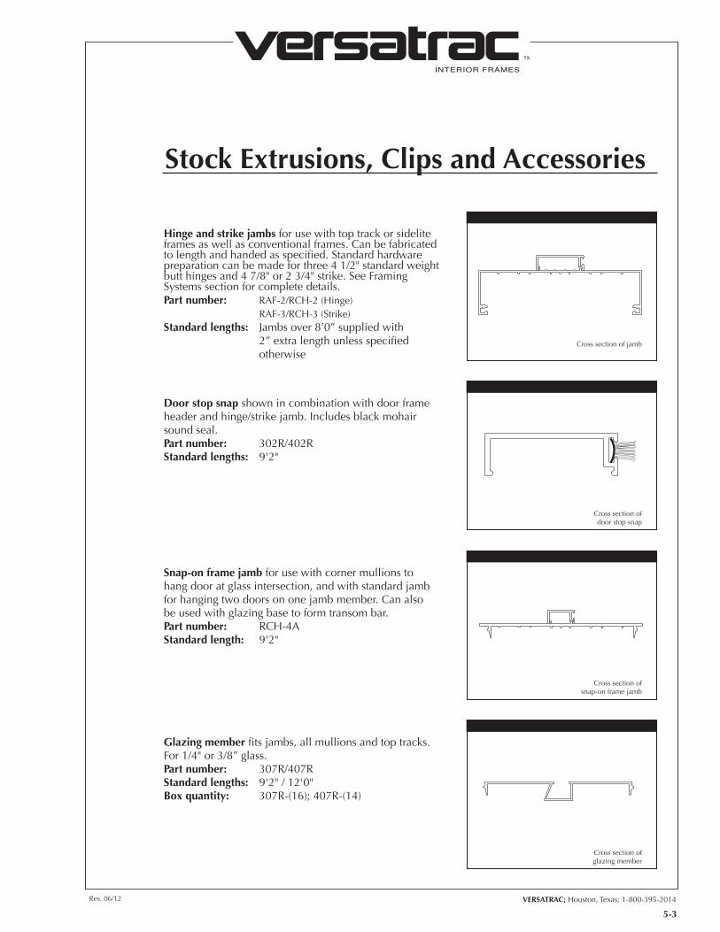
Hinge and strike jambs for use with top track or sidelite frames as well as conventional frames. Can be fabricated to length and handed as specified. Standard hardware preparation can be made for three 4 1/2" standard weight butt hinges and 4 7/8" or 2 3/4" strike. See Framing Systems section for complete details.Part number: RAF-2/RCH-2 (Hinge) RAF-3/RCH-3 (Strike)Standard lengths: Jambs over 8’0” supplied with 2” extra length unless specified otherwise
Door stop snap shown in combination with door frame header and hinge/strike jamb. Includes black mohair sound seal.Part number: 302R/402RStandard lengths: 9'2"
Snap-on frame jamb for use with corner mullions to hang door at glass intersection, and with standard jamb for hanging two doors on one jamb member. Can also be used with glazing base to form transom bar.Part number: RCH-4AStandard length: 9'2"
Glazing member fits jambs, all mullions and top tracks. For 1/4" or 3/8” glass.Part number: 307R/407RStandard lengths: 9'2" / 12'0"Box quantity: 307R-(16); 407R-(14)
Stock Extrusions, Clips and Accessories
Cross section ofdoor stop snap
Cross section of jamb
Cross section ofsnap-on frame jamb
Cross section ofglazing member

INTERIOR FRAMES
TM
Glazing mullion/jamb acts as mullion for glass, or as jamb where glass and drywall meet. For 1/4" or 3/8” glass.Part number: 306R/406RStandard lengths: 9'2" / 12'0"Box quantity: 306R-(8); 406R-(6)
Glazing H mullion fits No. RCH-4A, RCH-4, and No. 307R/407R snap-on sections; has rib guide for installation of drywall stud. Can be used as a mullion, separating glass units where glass and drywall meet. Can also be used for partition that ends at a round column, or as a special application header. Part number: 311R/411RStandard lengths: 9'2" / 12'0"Box quantity: 311R-(7); 411R-(5)
Glazing base and glazing snap fit snap-on sections. Designed as sill for sidelites and borrowed lites. Can be used as header for partial height solid partitions which have glass to ceiling. For 1/4" or 3/8” glass.Part number: 308R/309R/309RL 408R/409R/409RLStandard lengths: 10'7"Box quantity: 308R/309R/309RL-(8) 408R/409R/409RL-(6)
Horizontal glazing mullion is a combination of glazing member and glazing snap used as a horizontal mullion for 1/4" or 3/8” glass.Part number: 308M/309R/309RL 408M/409R/409RLStandard lengths: 10'7"Box quantity: 308R/309R/309RL-(8) 408R/409R/409RL-(6)
Stock Extrusions, Clips and Accessories
5-4
Cross section ofglazing mullion jamb
Cross section ofglazing H-mullion
Cross section ofglazing base and glazing snap
Cross section ofhorizontal glazing mullion
INTERIOR FRAMES
TM
VERSATRAC; Houston, Texas; 1-800-395-2014Rev. 06/12
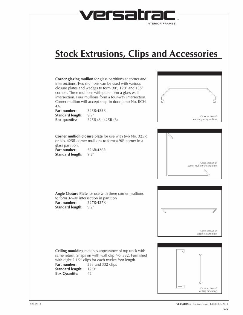
Corner glazing mullion for glass partitions at corner and intersections. Two mullions can be used with various closure plates and wedges to form 90°, 120° and 135° corners. Three mullions with plate form a glass wall intersection. Four mullions form a four-way intersection. Corner mullion will accept snap-in door jamb No. RCH-4A.Part number: 325R/425RStandard length: 9'2"Box quantity: 325R-(8); 425R-(6)
Corner mullion closure plate for use with two No. 325R or No. 425R corner mullions to form a 90° corner in a glass partition.Part number: 326R/426RStandard length: 9'2"
Angle Closure Plate for use with three corner mullions to form 3-way intersection in partitionPart number: 327R/427RStandard length: 9'2"
Ceiling moulding matches appearance of top track with same return. Snaps on with wall clip No. 332. Furnished with eight 2 1/2" clips for each twelve foot length.Part number: 333 and 332 clipsStandard length: 12'0"Box Quantity: 42
Stock Extrusions, Clips and Accessories
5-5
Cross section of corner glazing mullion
Cross section of corner mullion closure plate
Cross section of angle closure plate
Cross section of ceiling moulding
INTERIOR FRAMES
TM
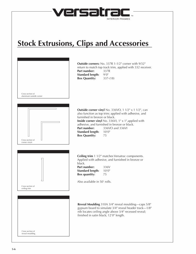
Outside corners: No. 337R 1-1/2" corner with 9/32" return to match top track trim, applied with 332 receiver.Part number: 337RStandard length: 9'0"Box Quantity: 337-(18)
Outside corner vinyl No. 336VO, 1 1/2" x 1 1/2", can also function as top trim; applied with adhesive, and furnished in bronze or black.Inside corner vinyl No. 336VI, 1" x 1",applied with adhesive, and furnished in bronze or black.Part number: 336VO and 336VIStandard length: 10'0"Box Quantity: 75
Ceiling trim 1 1/2" matches Versatrac components. Applied with adhesive, and furnished in bronze or black.Part number: 336VStandard length: 10'0"Box quantity: 75
Also available in 50' rolls.
Stock Extrusions, Clips and Accessories
5-6
Cross section of aluminum outside corner
Cross section of corner vinyls
Cross section of ceiling trim
Reveal Moulding 310A 3/4" reveal moulding—caps 5/8" gypsum board to simulate 3/4" reveal header track—1/8" nib locates ceiling angle above 3/4" recessed reveal; finished in satin black; 12'0" length.
Cross section of reveal moulding
INTERIOR FRAMES
TM
VERSATRAC; Houston, Texas; 1-800-395-2014Rev. 06/12
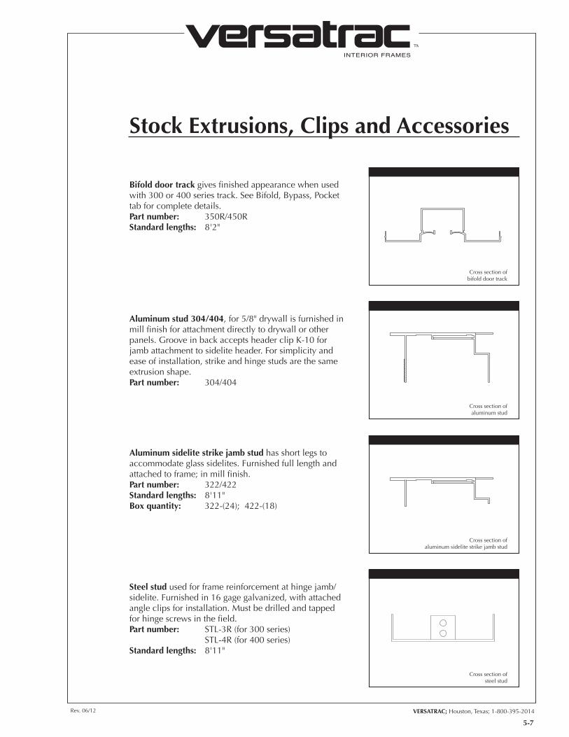
Bifold door track gives finished appearance when used with 300 or 400 series track. See Bifold, Bypass, Pocket tab for complete details.Part number: 350R/450RStandard lengths: 8'2"
Aluminum stud 304/404, for 5/8" drywall is furnished in mill finish for attachment directly to drywall or other panels. Groove in back accepts header clip K-10 for jamb attachment to sidelite header. For simplicity and ease of installation, strike and hinge studs are the same extrusion shape.Part number: 304/404
Aluminum sidelite strike jamb stud has short legs to accommodate glass sidelites. Furnished full length and attached to frame; in mill finish.Part number: 322/422Standard lengths: 8'11"Box quantity: 322-(24); 422-(18)
Steel stud used for frame reinforcement at hinge jamb/sidelite. Furnished in 16 gage galvanized, with attached angle clips for installation. Must be drilled and tapped for hinge screws in the field.Part number: STL-3R (for 300 series) STL-4R (for 400 series)Standard lengths: 8'11"
Stock Extrusions, Clips and Accessories
5-7
Cross section of bifold door track
Cross section of aluminum stud
Cross section of aluminum sidelite strike jamb stud
Cross section of steel stud
INTERIOR FRAMES
TM
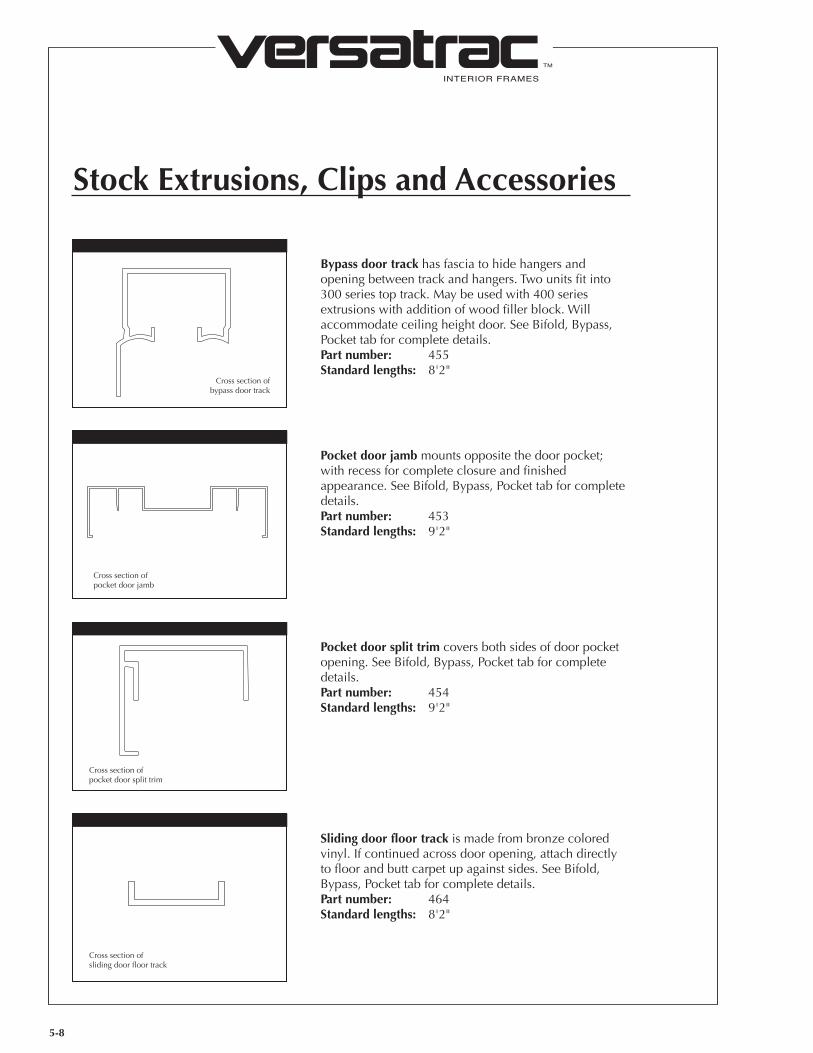
Bypass door track has fascia to hide hangers and opening between track and hangers. Two units fit into 300 series top track. May be used with 400 series extrusions with addition of wood filler block. Will accommodate ceiling height door. See Bifold, Bypass, Pocket tab for complete details.Part number: 455Standard lengths: 8'2"
Stock Extrusions, Clips and Accessories
Pocket door jamb mounts opposite the door pocket; with recess for complete closure and finished appearance. See Bifold, Bypass, Pocket tab for complete details.Part number: 453Standard lengths: 9'2"
Pocket door split trim covers both sides of door pocket opening. See Bifold, Bypass, Pocket tab for complete details.Part number: 454Standard lengths: 9'2"
Sliding door floor track is made from bronze colored vinyl. If continued across door opening, attach directly to floor and butt carpet up against sides. See Bifold, Bypass, Pocket tab for complete details.Part number: 464Standard lengths: 8'2"
5-8
Cross section of bypass door track
Cross section of pocket door jamb
Cross section of pocket door split trim
Cross section of sliding door floor track

INTERIOR FRAMES
TM
VERSATRAC; Houston, Texas; 1-800-395-2014Rev. 06/12
Versatrim Glazing Snap-in fits jambs and mullions.Part number: 377/477Standard length: 9'2"
Versatrim Shallow Glazing Snap-in available for 1 1/2” trim.Part number: 377S/477SStandard length: 9'2"
Versatrim Glazing Mullion jamb acts as a mullion or header for glass, or as a jamb where glass and drywall meet.Part number: 376S/476SStandard length: 9'2"
Versatrim Partition Casing is used for cased openings and double acting frames. Serves as a vertical end cap for wall ending at columns or window mullions.Part number: 373/473Standard length: 9'2"
Versatrim Jamb Material used for header as well as for hinge and strike jambs.Part number: VT-1 Header VT-2 Hinge Jamb VT-3 Strike JambStandard lengths: Fabricated to job requirements. Jambs over 8'0" supplied with 2" extra length unless specified otherwise.
Stock Extrusions, Clips and Accessories
5-9
Cross section of Versatrim jamb material
Cross section of Versatrim partition casing
Cross section of Versatrim glazing mullion
Cross section of Versatrim glazing snap-in
INTERIOR FRAMES
TM
Stock Extrusions, Clips and Accessories
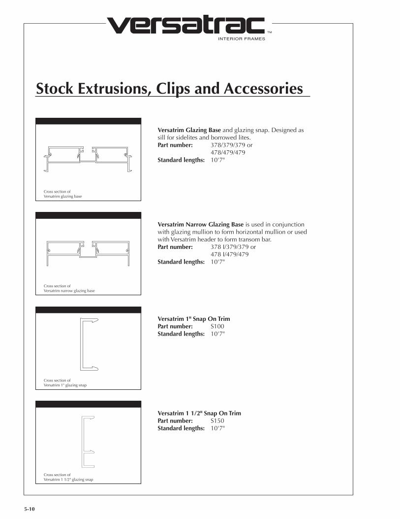
Versatrim Glazing Base and glazing snap. Designed as sill for sidelites and borrowed lites.Part number: 378/379/379 or 478/479/479Standard lengths: 10'7"
Versatrim Narrow Glazing Base is used in conjunction with glazing mullion to form horizontal mullion or used with Versatrim header to form transom bar.Part number: 378 I/379/379 or 478 I/479/479Standard lengths: 10'7"
Versatrim 1" Snap On TrimPart number: S100Standard lengths: 10'7"
Versatrim 1 1/2" Snap On TrimPart number: S150Standard lengths: 10'7"
5-10
Cross section of Versatrim glazing base
Cross section of Versatrim narrow glazing base
Cross section of Versatrim 1" glazing snap
Cross section of Versatrim 1 1/2" glazing snap
INTERIOR FRAMES
TM
VERSATRAC; Houston, Texas; 1-800-395-2014Rev. 06/12
Cross section of mohair sound seal
Stock Extrusions, Clips and Accessories
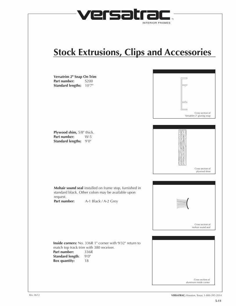
Versatrim 2" Snap On TrimPart number: S200Standard lengths: 10'7"
Plywood shim, 5/8" thick.Part number: W-5Standard lengths: 9'0"
Mohair sound seal installed on frame stop, furnished in standard black. Other colors may be available upon request.Part number: A-1 Black / A-2 Grey
5-11
Cross section of Versatrim 2" glazing snap
Cross section of plywood shim
Cross section of aluminum inside corner
Inside corners: No. 336R 1" corner with 9/32" return to match top track trim with 380 receiver.Part number: 336RStandard length: 9'0"Box quantity: 18
INTERIOR FRAMES
TM
Stock Extrusions, Clips and Accessories
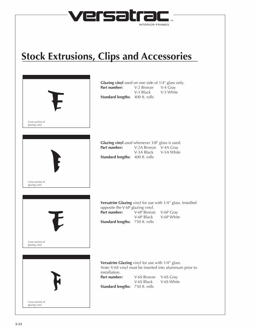
Glazing vinyl used on one side of 1/4" glass only.Part number: V-2 Bronze V-4 Gray V-3 Black V-5 WhiteStandard lengths: 400 ft. rolls
Glazing vinyl used whenever 3/8" glass is used.Part number: V-2A Bronze V-4A Gray V-3A Black V-5A WhiteStandard lengths: 400 ft. rolls
Versatrim Glazing vinyl for use with 1/4” glass. Installed opposite the V-6P glazing vinyl.Part number: V-6P Bronze V-6P Gray V-6P Black V-6P WhiteStandard lengths: 750 ft. rolls
Versatrim Glazing vinyl for use with 1/4” glass. Note: V-6S vinyl must be inserted into aluminum prior to installation.Part number: V-6S Bronze V-6S Gray V-6S Black V-6S WhiteStandard lengths: 750 ft. rolls
5-12
Cross section of glazing vinyl
Cross section of glazing vinyl
Cross section of glazing vinyl
Cross section of glazing vinyl

INTERIOR FRAMES
TM
VERSATRAC; Houston, Texas; 1-800-395-2014Rev. 06/12
Stock Extrusions, Clips and Accessories
Cased opening clip attached directly to vertical steel stud. Drywall allows positive snap-on mounting of cased opening 313R or 413R at wall ends without use of adhesive or exposed screws.Part number: K-20R/K-40R
Straight alignment plate fits inside top track 303R or 403R to ensure perfect alignment at all butt joints.Part number: K-5R
Corner alignment plate mounts in back to ensure top track alignment at 90° cornerPart number: K-6
Glazing clip used for connecting vertical and horizontal glazing mullions when using 303R or 403R top track as header.Part number: K-2
5-13
Cased opening clip
Bypass door track
Corner alignment plate
Glazing Clip
INTERIOR FRAMES
TM
Stock Extrusions, Clips and Accessories
5-14
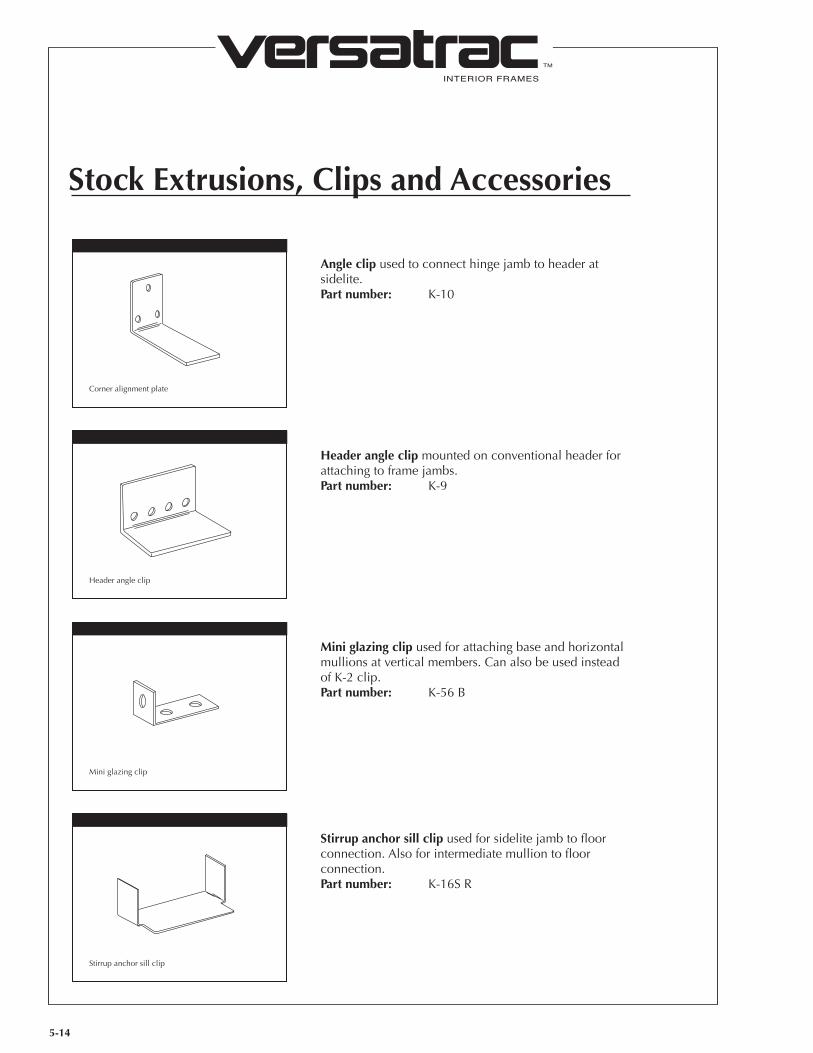
Angle clip used to connect hinge jamb to header at sidelite.Part number: K-10
Header angle clip mounted on conventional header for attaching to frame jambs.Part number: K-9
Mini glazing clip used for attaching base and horizontal mullions at vertical members. Can also be used instead of K-2 clip.Part number: K-56 B
Stirrup anchor sill clip used for sidelite jamb to floor connection. Also for intermediate mullion to floor connection.Part number: K-16S R
Corner alignment plate
Header angle clip
Mini glazing clip
Stirrup anchor sill clip
INTERIOR FRAMES
TM
VERSATRAC; Houston, Texas; 1-800-395-2014Rev. 06/12
Stock Extrusions, Clips and Accessories
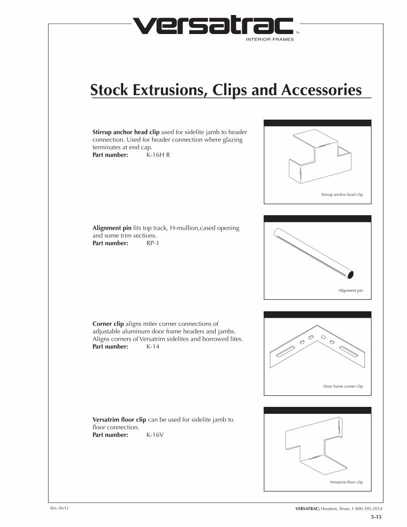
Stirrup anchor head clip used for sidelite jamb to header connection. Used for header connection where glazing terminates at end cap.Part number: K-16H R
Alignment pin fits top track, H-mullion,cased opening and some trim sections.Part number: RP-1
Corner clip aligns miter corner connections of adjustable aluminum door frame headers and jambs. Aligns corners of Versatrim sidelites and borrowed lites.Part number: K-14
Versatrim floor clip can be used for sidelite jamb to floor connection.Part number: K-16V
5-15
Stirrup anchor head clip
Alignment pin
Door frame corner clip
Versatrim floor clip
INTERIOR FRAMES
TM
Stock Extrusions, Clips and Accessories
5-16
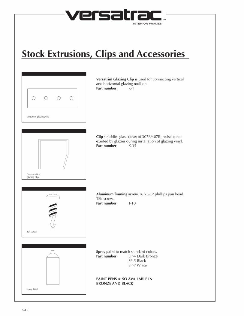
Versatrim Glazing Clip is used for connecting vertical and horizontal glazing mullion.Part number: K-1
Clip straddles glass offset of 307R/407R; resists force exerted by glazier during installation of glazing vinyl.Part number: K-35
Aluminum framing screw 16 x 5/8" phillips pan head TEK screw.Part number: T-10
Versatrim glazing clip
Cross sectionglazing clip
Tek screw
Spray paint to match standard colors.Part number: SP-4 Dark Bronze SP-5 Black SP-7 White
PAINT PENS ALSO AVAILABLE IN BRONZE AND BLACK
Spray Paint
INTERIOR FRAMES
TM
VERSATRAC; Houston, Texas; 1-800-395-2014Rev. 06/12
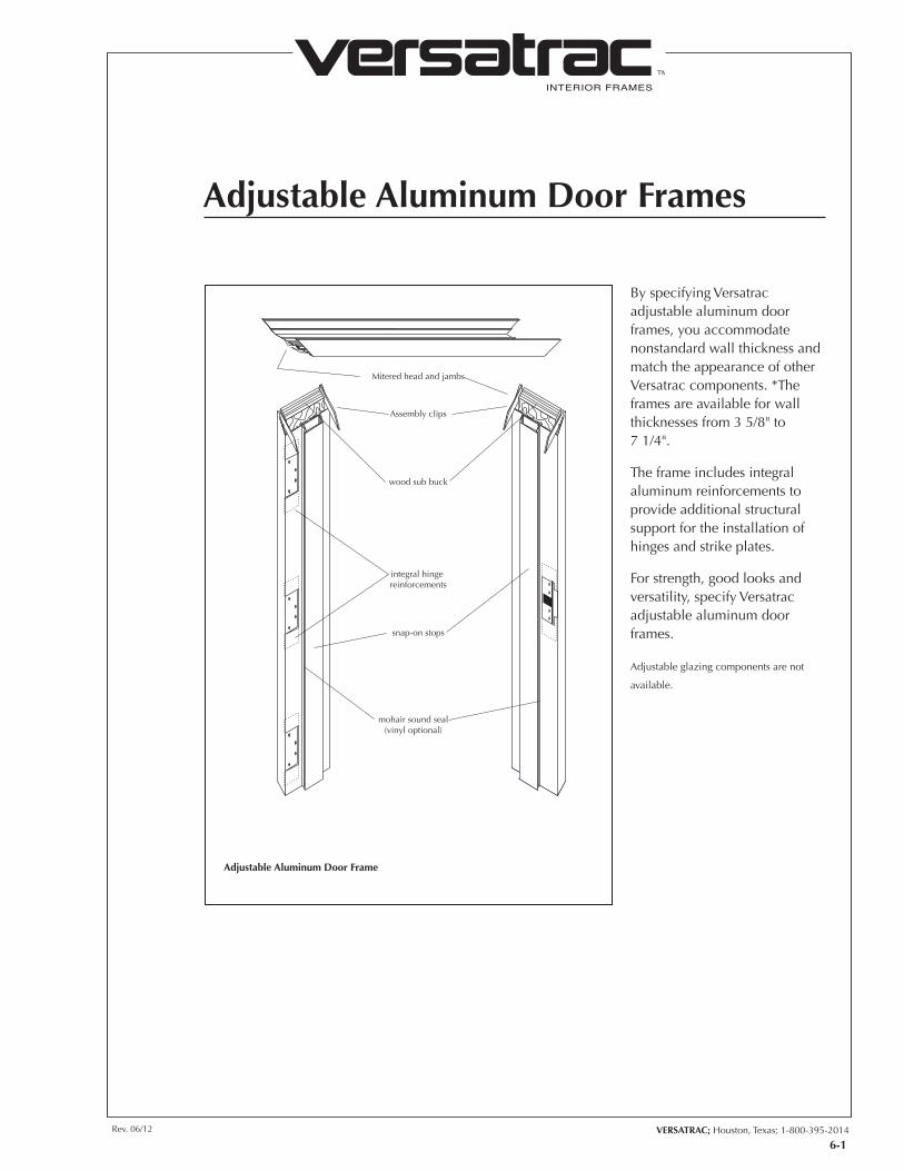
Mitered head and jambs
Assembly clips
wood sub buck
integral hinge reinforcements
snap-on stops
mohair sound seal(vinyl optional)
6-1
Adjustable Aluminum Door Frames
Adjustable Aluminum Door Frame
By specifying Versatrac adjustable aluminum door frames, you accommodate nonstandard wall thickness and match the appearance of other Versatrac components. *The frames are available for wall thicknesses from 3 5/8" to 7 1/4".
The frame includes integral aluminum reinforcements to provide additional structural support for the installation of hinges and strike plates.
For strength, good looks and versatility, specify Versatrac adjustable aluminum door frames.
Adjustable glazing components are not
available.
INTERIOR FRAMES
TM
Adjustable Aluminum Door Frames
INTERIOR FRAMES
TM
VERSATRAC; Houston, Texas; 1-800-395-2014Rev. 06/12
6-3
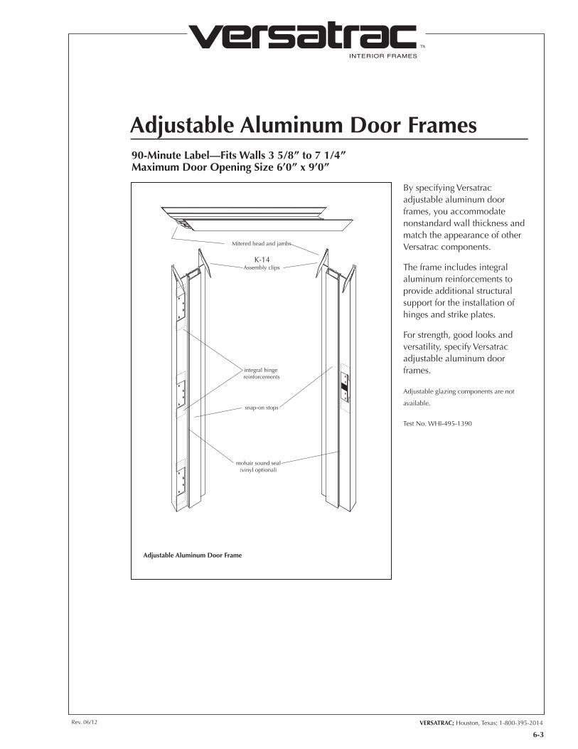
Mitered head and jambs
Assembly clips
integral hinge reinforcements
snap-on stops
mohair sound seal(vinyl optional)
K-14
Adjustable Aluminum Door Frames
Adjustable Aluminum Door Frame
By specifying Versatrac adjustable aluminum door frames, you accommodate nonstandard wall thickness and match the appearance of other Versatrac components.
The frame includes integral aluminum reinforcements to provide additional structural support for the installation of hinges and strike plates.
For strength, good looks and versatility, specify Versatrac adjustable aluminum door frames.
Adjustable glazing components are not
available.
Test No. WHI-495-1390
90-Minute Label—Fits Walls 3 5/8” to 7 1/4”Maximum Door Opening Size 6’0” x 9’0”
INTERIOR FRAMES
TM
Adjustable Aluminum Door Frames
6-4
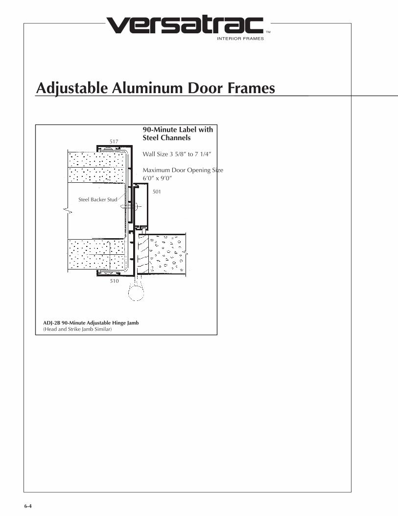
90-Minute Label with Steel Channels
Wall Size 3 5/8” to 7 1/4”
Maximum Door Opening Size 6’0” x 9’0”
517
501
510
Steel Backer Stud
ADJ-2B 90-Minute Adjustable Hinge Jamb(Head and Strike Jamb Similar)
INTERIOR FRAMES
TM
VERSATRAC; Houston, Texas; 1-800-395-2014Rev. 06/12
6-5
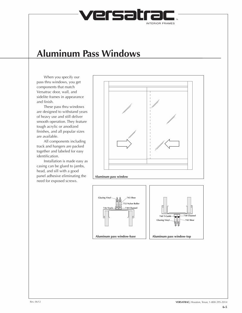
Aluminum Pass Windows
When you specify our pass thru windows, you get components that match Versatrac door, wall, and sidelite frames in appearance and finish.
These pass thru windows are designed to withstand years of heavy use and still deliver smooth operation. They feature tough acrylic or anodized finishes, and all popular sizes are available.
All components including track and hangers are packed together and labeled for easy identification.
Installation is made easy as casing can be glued to jambs, head, and sill with a good panel adhesive eliminating the need for exposed screws.
Glazing Vinyl 743 Shoe
730 Channel726 Track
752 Nylon Roller
Glazing Vinyl 743 Shoe
730 Channel760 T-Guide
Aluminum pass window
Aluminum pass window-base Aluminum pass window-top
INTERIOR FRAMES
TM
VERSATRAC; Houston, Texas; 1-800-395-2014Rev. 06/12
7-1
VERSATRAC; Houston, Texas; 1-800-395-2014
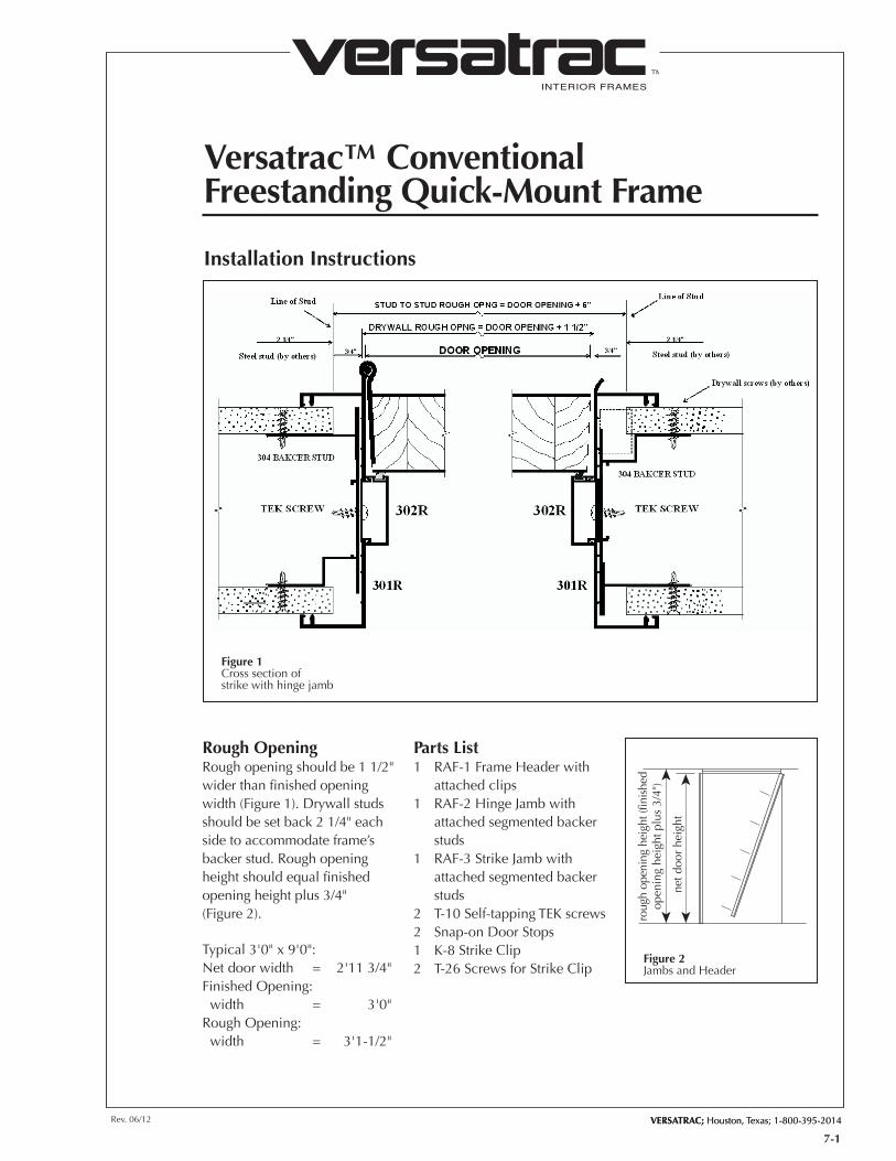
Versatrac™ ConventionalFreestanding Quick-Mount Frame
Installation Instructions
Rough OpeningRough opening should be 1 1/2" wider than finished opening width (Figure 1). Drywall studs should be set back 2 1/4" each side to accommodate frame’s backer stud. Rough opening height should equal finished opening height plus 3/4" (Figure 2).
Typical 3'0" x 9'0":Net door width = 2'11 3/4"Finished Opening: width = 3'0"Rough Opening: width = 3'1-1/2"
Parts List1 RAF-1 Frame Header with
attached clips1 RAF-2 Hinge Jamb with
attached segmented backer studs
1 RAF-3 Strike Jamb with attached segmented backer studs
2 T-10 Self-tapping TEK screws2 Snap-on Door Stops1 K-8 Strike Clip2 T-26 Screws for Strike Clip
Figure 1Cross section ofstrike with hinge jamb
roug
h op
enin
g he
ight
(fin
ishe
dop
enin
g he
ight
plu
s 3/
4")
net d
oor
heig
ht
Figure 2Jambs and Header
INTERIOR FRAMES
TM
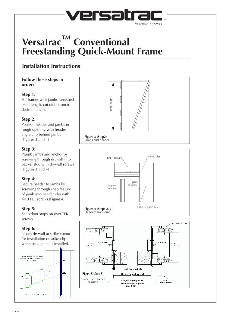
Versatrac™ ConventionalFreestanding Quick-Mount Frame
7-2
Installation Instructions
Follow these steps in order:
Step 1:For frames with jambs furnished extra length, cut off bottom to desired length.
Step 2:Position header and jambs in rough opening with header angle clip behind jambs (Figures 3 and 4)
Step 3:Plumb jambs and anchor by screwing through drywall into backer stud with drywall screws (Figures 3 and 4)
Step 4:Secure header to jambs by screwing through snap feature of jamb into header clip with T-10 TEK screws.(Figure 4)
Step 5:Snap door stops on over TEK screws.
Step 6:Notch drywall at strike cutout for installation of strike clip when strike plate is installed.
Jam
b le
ngth
attached clip
TEK screw
RAF-1 Header
RAF-2 or RAF-3 Jamb
Snap-onDoor Stop
Figure 3 (Step2)Jambs and header
Figure 4 (Steps 2, 4)Header/jamb joint
Figure 5 (Step 3)Cross section of strike and hinge jamb
INTERIOR FRAMES
TM
VERSATRAC; Houston, Texas; 1-800-395-2014Rev. 06/12
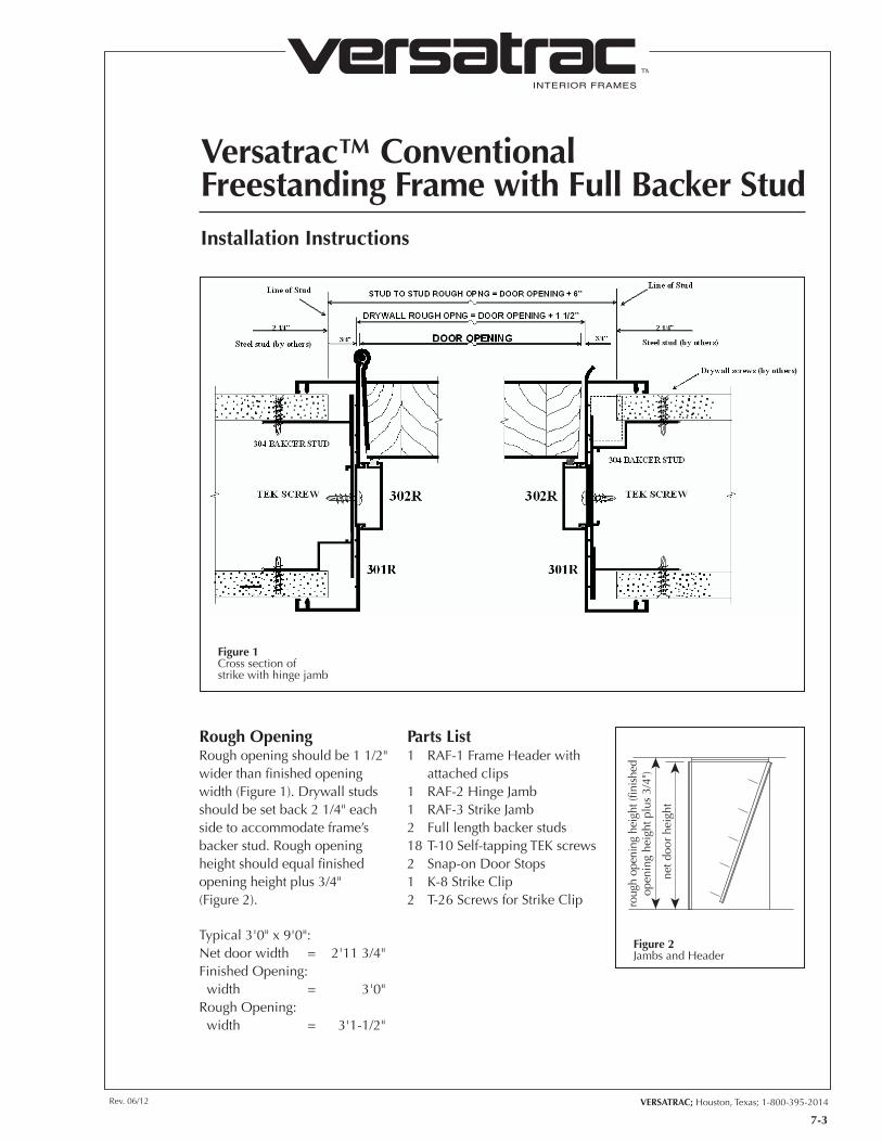
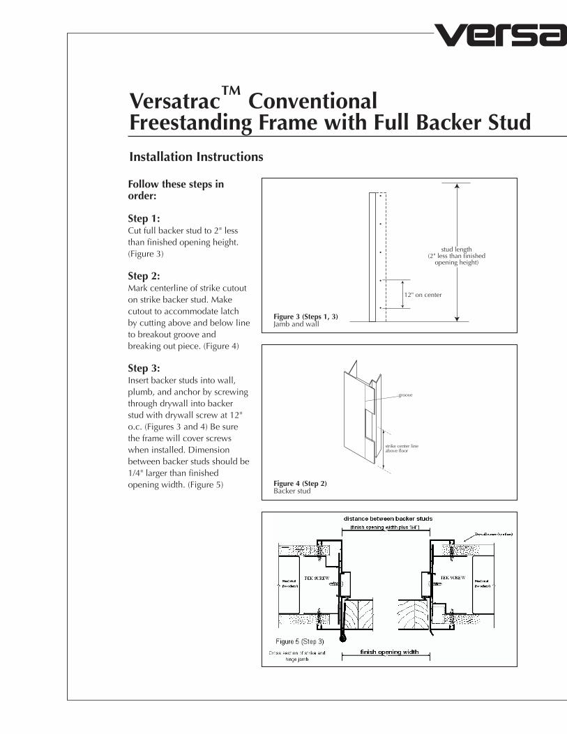
Versatrac™ ConventionalFreestanding Frame with Full Backer Stud
7-3
Installation Instructions
Rough OpeningRough opening should be 1 1/2" wider than finished opening width (Figure 1). Drywall studs should be set back 2 1/4" each side to accommodate frame’s backer stud. Rough opening height should equal finished opening height plus 3/4" (Figure 2).
Typical 3'0" x 9'0":Net door width = 2'11 3/4"Finished Opening: width = 3'0"Rough Opening: width = 3'1-1/2"
Parts List1 RAF-1 Frame Header with
attached clips1 RAF-2 Hinge Jamb1 RAF-3 Strike Jamb2 Full length backer studs18 T-10 Self-tapping TEK screws2 Snap-on Door Stops1 K-8 Strike Clip2 T-26 Screws for Strike Clip
Figure 1Cross section ofstrike with hinge jamb
roug
h op
enin
g he
ight
(fin
ishe
dop
enin
g he
ight
plu
s 3/
4")
net d
oor
heig
ht
Figure 2Jambs and Header
INTERIOR FRAMES
TM
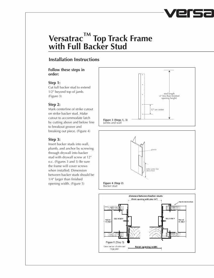
Versatrac™ ConventionalFreestanding Frame with Full Backer StudInstallation Instructions
Follow these steps in order:
Step 1:Cut full backer stud to 2" less than finished opening height. (Figure 3)
Step 2:Mark centerline of strike cutout on strike backer stud. Make cutout to accommodate latch by cutting above and below line to breakout groove and breaking out piece. (Figure 4)
Step 3:Insert backer studs into wall, plumb, and anchor by screwing through drywall into backer stud with drywall screw at 12" o.c. (Figures 3 and 4) Be sure the frame will cover screws when installed. Dimension between backer studs should be 1/4" larger than finished opening width. (Figure 5)
12" on center
stud length(2" less than finished
opening height)
groove
strike center lineabove floor
Figure 3 (Steps 1, 3)Jamb and wall
Figure 4 (Step 2)Backer stud
Figure 5 (Step 3)Cross section of strike and hinge jambs

Rev. 06/12 VERSATRAC; Houston, Texas; 1-800-395-2014
INTERIOR FRAMES
TM
7-4
attached clip
TEK screw
RAF-1 Header
RAF-2 or RAF-3 Jamb
Snap-onDoor Stop
Step 4:For jambs furnished extra length, cut to desired length.
Step 5:Position header and jambs in rough opening with header clips behind jambs. Anchor jambs to backer studs with T-10 TEK screws.
Step 6:Secure jamb to header clip by screwing through snap feature of jamb into header clip with T-10 TEK screw. (Figure 6)
Step 7:Snap door stops on over TEK screws.
Step 8:Notch drywall at strike cutout for installation of strike clip when strike plate is installed.
Figure 6 (Step 6)Header/jamb joint
INTERIOR FRAMES
TM
VERSATRAC; Houston, Texas; 1-800-395-2014Rev. 06/12
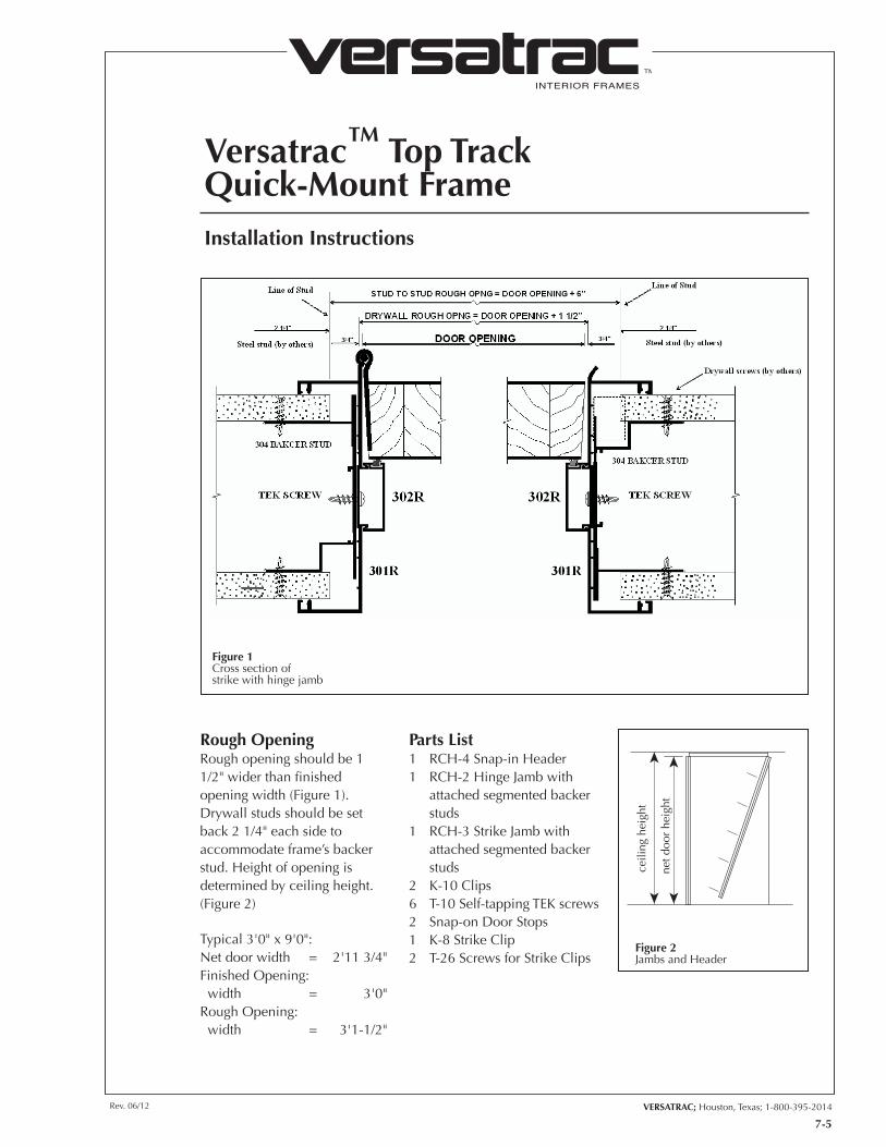
Versatrac™ Top TrackQuick-Mount Frame
7-5
Installation Instructions
Rough OpeningRough opening should be 1 1/2" wider than finished opening width (Figure 1). Drywall studs should be set back 2 1/4" each side to accommodate frame’s backer stud. Height of opening is determined by ceiling height. (Figure 2)
Typical 3'0" x 9'0":Net door width = 2'11 3/4"Finished Opening: width = 3'0"Rough Opening: width = 3'1-1/2"
Parts List1 RCH-4 Snap-in Header1 RCH-2 Hinge Jamb with
attached segmented backer studs
1 RCH-3 Strike Jamb with attached segmented backer studs
2 K-10 Clips6 T-10 Self-tapping TEK screws2 Snap-on Door Stops1 K-8 Strike Clip2 T-26 Screws for Strike Clips
Figure 1Cross section ofstrike with hinge jamb
ceili
ng h
eigh
t
net d
oor
heig
ht
Figure 2Jambs and Header
INTERIOR FRAMES
TM
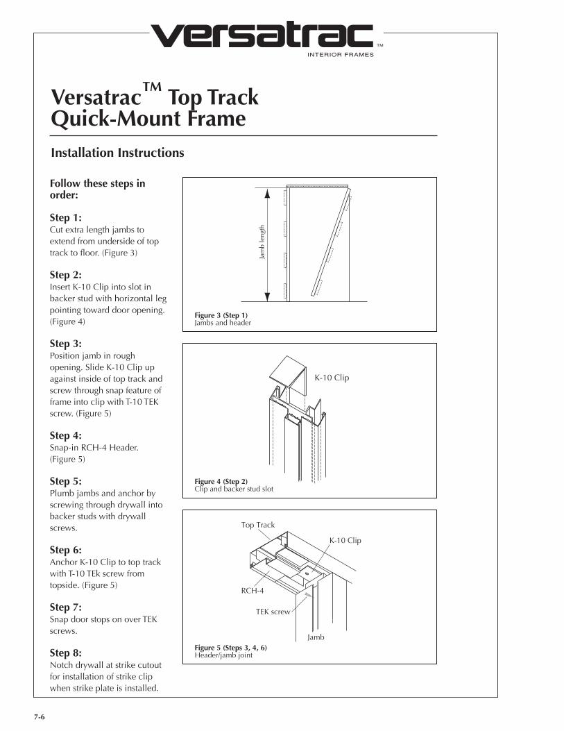
Versatrac™ Top TrackQuick-Mount Frame
7-6
Installation Instructions
Follow these steps in order:
Step 1:Cut extra length jambs to extend from underside of top track to floor. (Figure 3)
Step 2:Insert K-10 Clip into slot in backer stud with horizontal leg pointing toward door opening. (Figure 4)
Step 3:Position jamb in rough opening. Slide K-10 Clip up against inside of top track and screw through snap feature of frame into clip with T-10 TEK screw. (Figure 5)
Step 4:Snap-in RCH-4 Header. (Figure 5)
Step 5:Plumb jambs and anchor by screwing through drywall into backer studs with drywall screws.
Step 6:Anchor K-10 Clip to top track with T-10 TEk screw from topside. (Figure 5)
Step 7:Snap door stops on over TEK screws.
Step 8:Notch drywall at strike cutout for installation of strike clip when strike plate is installed.
Jam
b le
ngth
K-10 Clip
RCH-4
TEK screw
Top Track
K-10 Clip
Jamb
Figure 3 (Step 1)Jambs and header
Figure 4 (Step 2)Clip and backer stud slot
Figure 5 (Steps 3, 4, 6)Header/jamb joint
INTERIOR FRAMES
TM
VERSATRAC; Houston, Texas; 1-800-395-2014Rev. 06/12
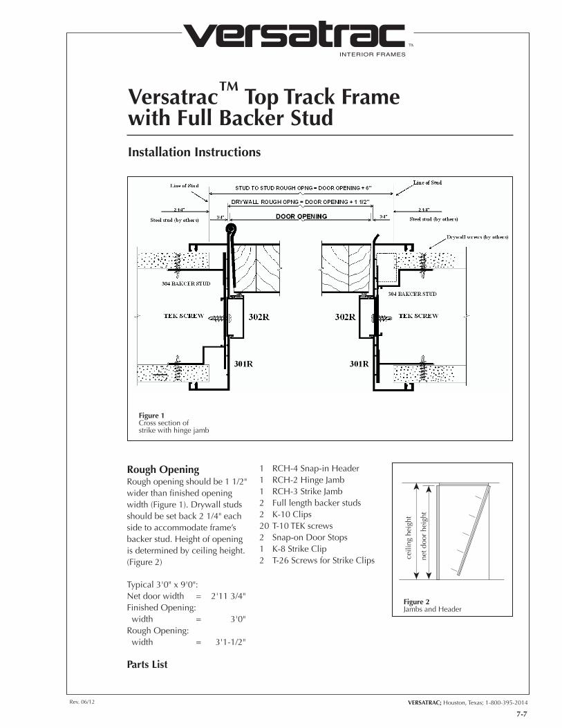
Versatrac™ Top Track Framewith Full Backer Stud
7-7
Installation Instructions
Rough OpeningRough opening should be 1 1/2" wider than finished opening width (Figure 1). Drywall studs should be set back 2 1/4" each side to accommodate frame’s backer stud. Height of opening is determined by ceiling height. (Figure 2)
Typical 3'0" x 9'0":Net door width = 2'11 3/4"Finished Opening: width = 3'0"Rough Opening: width = 3'1-1/2"
Parts List
1 RCH-4 Snap-in Header1 RCH-2 Hinge Jamb 1 RCH-3 Strike Jamb2 Full length backer studs2 K-10 Clips20 T-10 TEK screws2 Snap-on Door Stops1 K-8 Strike Clip2 T-26 Screws for Strike Clips
Figure 1Cross section ofstrike with hinge jamb
ceili
ng h
eigh
t
net d
oor
heig
ht
Figure 2Jambs and Header
INTERIOR FRAMES
TM
Versatrac™ Top Track Framewith Full Backer StudInstallation Instructions
Follow these steps in order:
Step 1:Cut full backer stud to extend 1/2" beyond top of jamb. (Figure 3)
Step 2:Mark centerline of strike cutout on strike backer stud. Make cutout to accommodate latch by cutting above and below line to breakout groove and breaking out piece. (Figure 4)
Step 3:Insert backer studs into wall, plumb, and anchor by screwing through drywall into backer stud with drywall screw at 12" o.c. (Figures 3 and 5) Be sure the frame will cover screws when installed. Dimension between backer studs should be 1/4" larger than finished opening width. (Figure 5)
12" on center
stud length(2" less than finished
opening height)
groove
strike center lineabove floor
Figure 3 (Steps 1, 3)Jambs and wall
Figure 4 (Step 2)Backer stud
Figure 5 (Step 3)Cross section of strike and hinge jambs
Rev. 06/12 VERSATRAC; Houston, Texas; 1-800-395-2014
INTERIOR FRAMES
TM
7-8
K-10 Clip
RCH-4
TEK screw
Top Track
K-10 Clip
Jamb
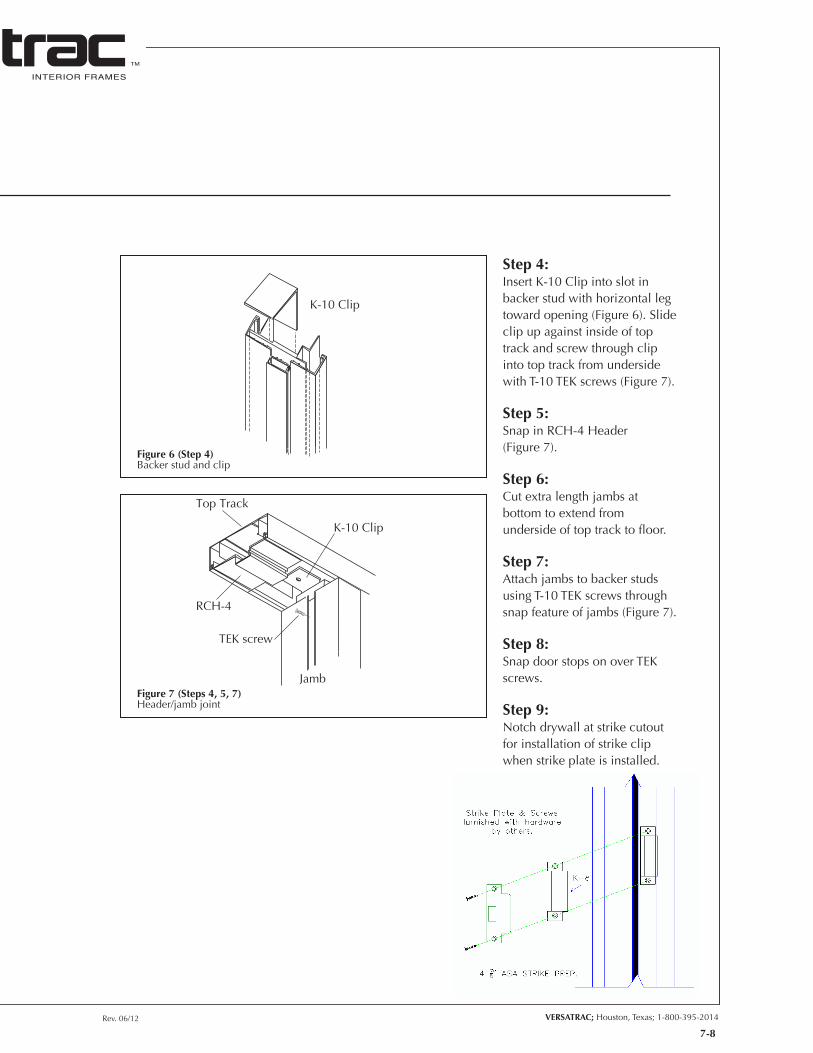
Step 4:Insert K-10 Clip into slot in backer stud with horizontal leg toward opening (Figure 6). Slide clip up against inside of top track and screw through clip into top track from underside with T-10 TEK screws (Figure 7).
Step 5:Snap in RCH-4 Header (Figure 7).
Step 6:Cut extra length jambs at bottom to extend from underside of top track to floor.
Step 7:Attach jambs to backer studs using T-10 TEK screws through snap feature of jambs (Figure 7).
Step 8:Snap door stops on over TEK screws.
Step 9:Notch drywall at strike cutout for installation of strike clip when strike plate is installed.
Figure 6 (Step 4)Backer stud and clip
Figure 7 (Steps 4, 5, 7)Header/jamb joint
INTERIOR FRAMES
TM
VERSATRAC; Houston, Texas; 1-800-395-2014Rev. 06/12
VersatrimSide-Snap Frame
7-9
Installation Instructions
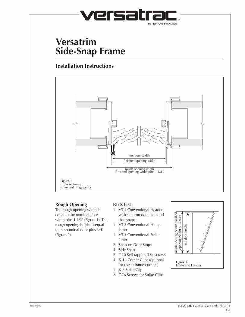
net door width
finished opening width
rough opening width(finished opening width plus 1 1/2")
Rough OpeningThe rough opening width is equal to the nominal door width plus 1 1/2" (Figure 1). The rough opening height is equal to the nominal door plus 3/4" (Figure 2).
Parts List1 VT-1 Conventional Header
with snap-on door stop and side snaps
1 VT-2 Conventional Hinge Jamb
1 VT-3 Conventional Strike Jamb
2 Snap-on Door Stops4 Side Snaps2 T-10 Self-tapping TEK screws4 K-14 Corner Clips (optional
for use at frame corners)1 K-8 Strike Clip2 T-26 Screws for Strike Clips
Figure 1Cross section ofstrike and hinge jambs
roug
h op
enin
g he
ight
(fin
ishe
dop
enin
g he
ight
plu
s 3/
4")
net d
oor
heig
ht
Figure 2Jambs and Header
INTERIOR FRAMES
TM
Versatrim Side-Snap Frame
7-10
Installation Instructions
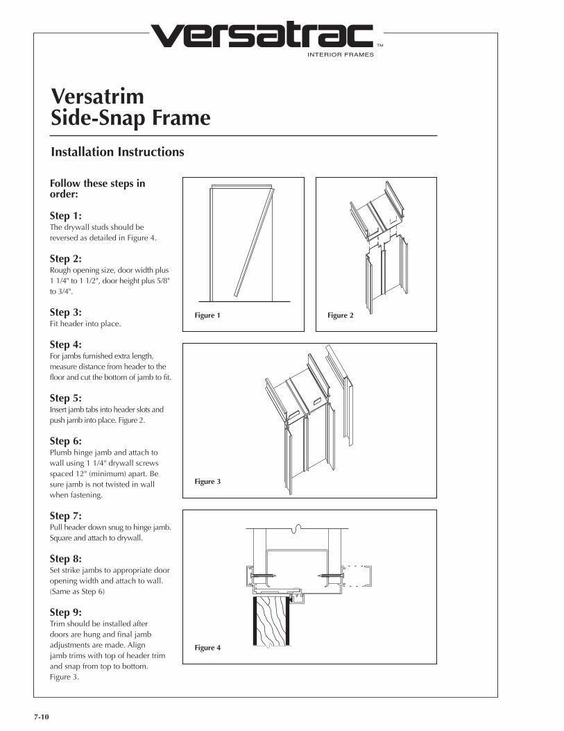
Follow these steps in order:
Step 1:The drywall studs should be reversed as detailed in Figure 4.
Step 2:Rough opening size, door width plus 1 1/4" to 1 1/2", door height plus 5/8" to 3/4".
Step 3:Fit header into place.
Step 4:For jambs furnished extra length, measure distance from header to the floor and cut the bottom of jamb to fit.
Step 5:Insert jamb tabs into header slots and push jamb into place. Figure 2.
Step 6:Plumb hinge jamb and attach to wall using 1 1/4" drywall screws spaced 12" (minimum) apart. Be sure jamb is not twisted in wall when fastening.
Step 7:Pull header down snug to hinge jamb. Square and attach to drywall.
Step 8:Set strike jambs to appropriate door opening width and attach to wall. (Same as Step 6)
Step 9:Trim should be installed after doors are hung and final jamb adjustments are made. Align jamb trims with top of header trim and snap from top to bottom.Figure 3.
Figure 1 Figure 2
Figure 3
Figure 4
INTERIOR FRAMES
TM
VERSATRAC; Houston, Texas; 1-800-395-2014Rev. 06/12
7-11
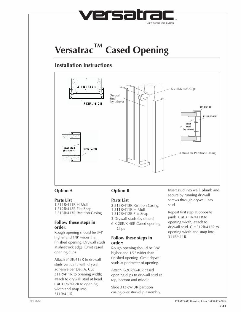
Versatrac™ Cased OpeningInstallation Instructions
K-20R/K-40R Clip
DrywallStud(by others)
313R/413R Partition Casing
SteelStud
(by others)
313R/413R
K-20R/K-40R
Option A
Parts List1 311R/411R H-Mull1 312R/412R Flat Snap2 313R/413R Partition Casing
Follow these steps in order:Rough opening should be 3/4" higher and 1/8" wider than finished opening. Drywall studs at sheetrock edge. Omit cased opening clips.
Attach 313R/413R to drywall studs vertically with drywall adhesive per Det. A. Cut 311R/411R to opening width; attach to drywall stud at head. Cut 312R/412R to opening width and snap into 311R/411R.
Option B
Parts List2 313R/413R Partition Casing1 311R/411R H-Mull1 312R/412R Flat Snap3 Drywall studs (by others)6 K-20R/K-40R Cased opening
Clips
Follow these steps in order:Rough opening should be 3/4" higher and 1/2" wider than finished opening. Omit drywall studs at perimeter of opening.
Attach K-20R/K-40R cased opening clips to drywall stud at top, bottom and middle
Slide 313R/413R partition casing over stud-clip assembly.
Insert stud into wall, plumb and secure by running drywall screws through drywall into stud.
Repeat first step at opposite jamb. Cut 311R/411R to opening width; attach to drywall stud. Cut 312R/412R to opening width and snap into 311R/411R.
INTERIOR FRAMES
TM
VERSATRAC; Houston, Texas; 1-800-395-2014Rev. 06/12
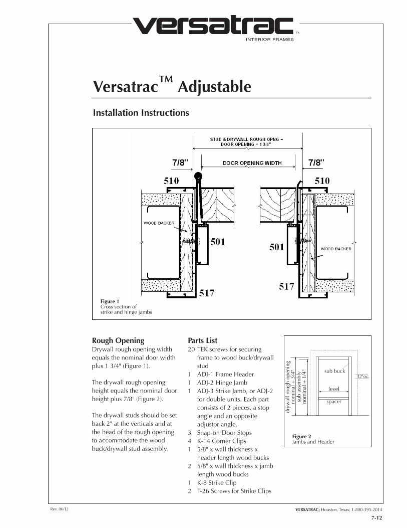
Versatrac™ Adjustable
7-12
Installation Instructions
Rough OpeningDrywall rough opening width equals the nominal door width plus 1 3/4" (Figure 1).
The drywall rough opening height equals the nominal door height plus 7/8" (Figure 2).
The drywall studs should be set back 2" at the verticals and at the head of the rough opening to accommodate the wood buck/drywall stud assembly.
Parts List20 TEK screws for securing
frame to wood buck/drywall stud
1 ADJ-1 Frame Header 1 ADJ-2 Hinge Jamb1 ADJ-3 Strike Jamb, or ADJ-2
for double units. Each part consists of 2 pieces, a stop angle and an opposite adjustor angle.
3 Snap-on Door Stops4 K-14 Corner Clips1 5/8" x wall thickness x
header length wood bucks2 5/8" x wall thickness x jamb
length wood bucks1 K-8 Strike Clip2 T-26 Screws for Strike Clips
Figure 1Cross section ofstrike and hinge jambs
level
sub buck12" o.c.
sub
asse
mbl
yno
min
al +
1/4
"
dryw
all r
ough
ope
ning
nom
inal
+ 3
/4"
spacer
Figure 2Jambs and Header
INTERIOR FRAMES
TM
Versatrac™ Adjustable
Installation Instructions
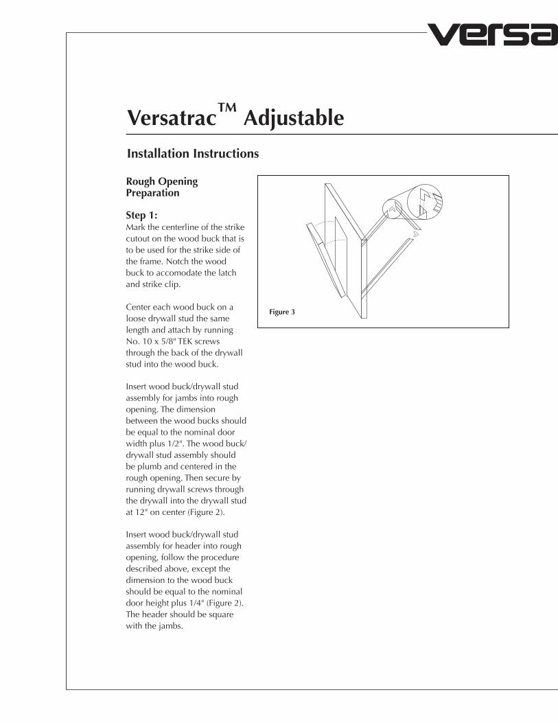
Rough Opening Preparation
Step 1:Mark the centerline of the strike cutout on the wood buck that is to be used for the strike side of the frame. Notch the wood buck to accomodate the latch and strike clip.
Center each wood buck on a loose drywall stud the same length and attach by running No. 10 x 5/8" TEK screws through the back of the drywall stud into the wood buck.
Insert wood buck/drywall stud assembly for jambs into rough opening. The dimension between the wood bucks should be equal to the nominal door width plus 1/2". The wood buck/drywall stud assembly should be plumb and centered in the rough opening. Then secure by running drywall screws through the drywall into the drywall stud at 12" on center (Figure 2).
Insert wood buck/drywall stud assembly for header into rough opening, follow the procedure described above, except the dimension to the wood buck should be equal to the nominal door height plus 1/4" (Figure 2). The header should be square with the jambs.
Figure 3

Rev. 06/12 VERSATRAC; Houston, Texas; 1-800-395-2014
INTERIOR FRAMES
TM
7-13
Follow these steps in order:
Step 1:For extra length jambs, cut off bottom to desired length.
Step 2:Match the jamb and header portions of the stop angle on the side of the opening according to the desired swing of the door. Connect together with K-14 clips (Figure 3).
Step 3:Repeat for adjustor angle portion of same on opposite side of wall.
Step 4:Lift adjustor angle side of frame into rough opening, and then stop angle side. Push each side tight against the wall and run a No. 10 x 1 1/4" TEK screw through snap features of frame into the wood buck at 12" on center maximum.
Step 5:Snap on door stops.
Step 6:Hang door.
Note:A furniture clamp can be helpful to hold two parts of the jamb together while fastening to wall. Care should be taken not to tighten too much, which would cause the face of the jamb to cup. Follow this procedure for both jambs and header. (Figure 4)
Figure 4
Figure 5
INTERIOR FRAMES
TM
VERSATRAC; Houston, Texas; 1-800-395-2014Rev. 06/12
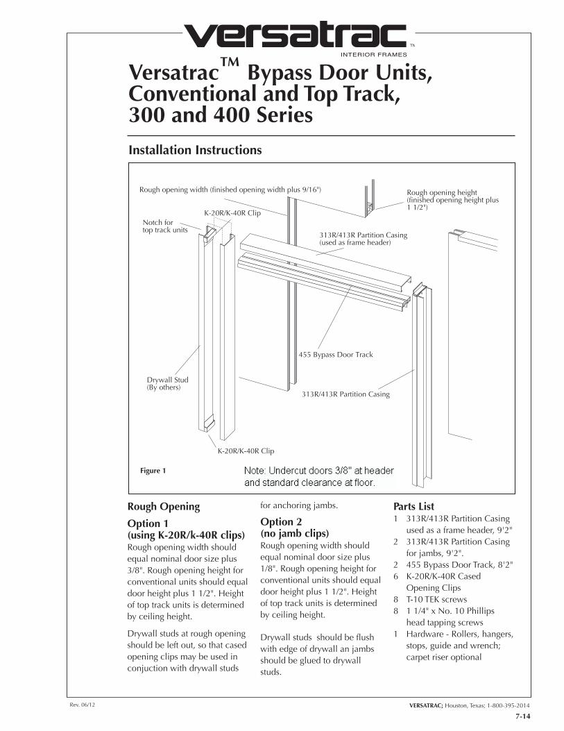
Versatrac™ Bypass Door Units,Conventional and Top Track, 300 and 400 Series
7-14
Installation Instructions
Drywall Stud(By others)
455 Bypass Door Track
313R/413R Partition Casing
313R/413R Partition Casing(used as frame header)
K-20R/K-40R Clip
K-20R/K-40R ClipNotch for top track units
Rough opening height(finished opening height plus 1 1/2")
Rough opening width (finished opening width plus 9/16")
Rough Opening
Option 1(using K-20R/k-40R clips)Rough opening width should equal nominal door size plus 3/8". Rough opening height for conventional units should equal door height plus 1 1/2". Height of top track units is determined by ceiling height.
Drywall studs at rough opening should be left out, so that cased opening clips may be used in conjuction with drywall studs
for anchoring jambs.
Option 2(no jamb clips)Rough opening width should equal nominal door size plus 1/8". Rough opening height for conventional units should equal door height plus 1 1/2". Height of top track units is determined by ceiling height.
Drywall studs should be flush with edge of drywall an jambs should be glued to drywall studs.
Parts List1 313R/413R Partition Casing
used as a frame header, 9'2"2 313R/413R Partition Casing
for jambs, 9'2".2 455 Bypass Door Track, 8'2"6 K-20R/K-40R Cased
Opening Clips8 T-10 TEK screws8 1 1/4" x No. 10 Phillips
head tapping screws1 Hardware - Rollers, hangers,
stops, guide and wrench; carpet riser optional
Figure 1
INTERIOR FRAMES
TM
Versatrac™ Bypass Door Units,Conventional and Top Track, 300 and 400 Series
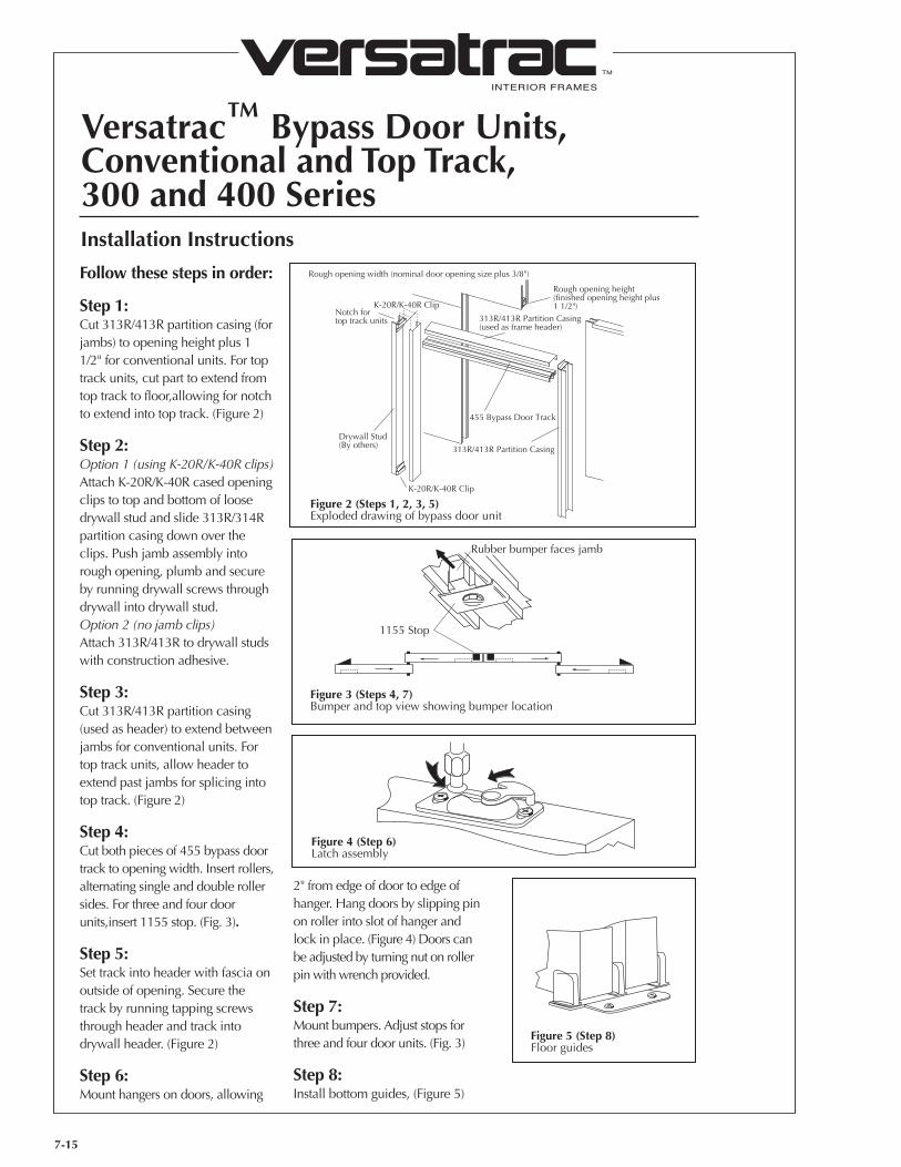
7-15
Installation Instructions
Follow these steps in order:
Step 1:Cut 313R/413R partition casing (for jambs) to opening height plus 1 1/2" for conventional units. For top track units, cut part to extend from top track to floor,allowing for notch to extend into top track. (Figure 2)
Step 2:Option 1 (using K-20R/K-40R clips)Attach K-20R/K-40R cased opening clips to top and bottom of loose drywall stud and slide 313R/314R partition casing down over the clips. Push jamb assembly into rough opening, plumb and secure by running drywall screws through drywall into drywall stud.Option 2 (no jamb clips)Attach 313R/413R to drywall studs with construction adhesive.
Step 3:Cut 313R/413R partition casing (used as header) to extend between jambs for conventional units. For top track units, allow header to extend past jambs for splicing into top track. (Figure 2)
Step 4:Cut both pieces of 455 bypass door track to opening width. Insert rollers, alternating single and double roller sides. For three and four door units,insert 1155 stop. (Fig. 3).
Step 5:Set track into header with fascia on outside of opening. Secure the track by running tapping screws through header and track into drywall header. (Figure 2)
Step 6:Mount hangers on doors, allowing
Drywall Stud(By others)
455 Bypass Door Track
313R/413R Partition Casing
313R/413R Partition Casing(used as frame header)
K-20R/K-40R Clip
K-20R/K-40R ClipNotch for top track units
Rough opening height(finished opening height plus 1 1/2")
Rough opening width (nominal door opening size plus 3/8")
1155 Stop
Rubber bumper faces jamb
Figure 2 (Steps 1, 2, 3, 5)Exploded drawing of bypass door unit
Figure 3 (Steps 4, 7)Bumper and top view showing bumper location
Figure 4 (Step 6)Latch assembly
Figure 5 (Step 8)Floor guides
2" from edge of door to edge of hanger. Hang doors by slipping pin on roller into slot of hanger and lock in place. (Figure 4) Doors can be adjusted by turning nut on roller pin with wrench provided.
Step 7:Mount bumpers. Adjust stops for three and four door units. (Fig. 3)
Step 8:Install bottom guides, (Figure 5)
INTERIOR FRAMES
TM
VERSATRAC; Houston, Texas; 1-800-395-2014Rev. 06/12
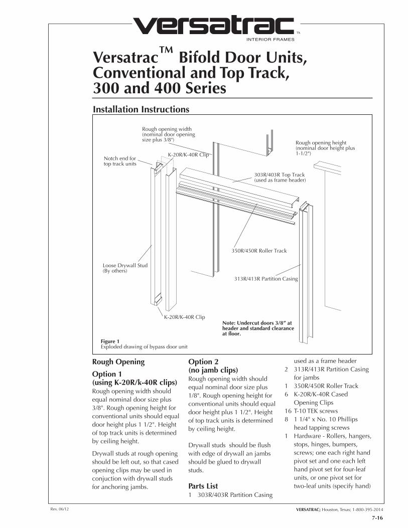
Versatrac™ Bifold Door Units,Conventional and Top Track,300 and 400 Series
7-16
Installation Instructions
Loose Drywall Stud(By others)
350R/450R Roller Track
313R/413R Partition Casing
303R/403R Top Track(used as frame header)
K-20R/K-40R Clip
K-20R/K-40R ClipNotch end fortop track units
Rough opening height(nominal door height plus 1-1/2")
Rough opening width(nominal door opening size plus 3/8")
Note: Undercut doors 3/8” at header and standard clearance at floor.
Figure 1Exploded drawing of bypass door unit
Rough Opening
Option 1(using K-20R/k-40R clips)Rough opening width should equal nominal door size plus 3/8". Rough opening height for conventional units should equal door height plus 1 1/2". Height of top track units is determined by ceiling height.
Drywall studs at rough opening should be left out, so that cased opening clips may be used in conjuction with drywall studs for anchoring jambs.
Option 2(no jamb clips)Rough opening width should equal nominal door size plus 1/8". Rough opening height for conventional units should equal door height plus 1 1/2". Height of top track units is determined by ceiling height.
Drywall studs should be flush with edge of drywall an jambs should be glued to drywall studs.
Parts List1 303R/403R Partition Casing
used as a frame header2 313R/413R Partition Casing
for jambs1 350R/450R Roller Track6 K-20R/K-40R Cased
Opening Clips16 T-10 TEK screws8 1 1/4" x No. 10 Phillips
head tapping screws1 Hardware - Rollers, hangers,
stops, hinges, bumpers, screws; one each right hand pivot set and one each left hand pivot set for four-leaf units, or one pivot set for two-leaf units (specify hand)
INTERIOR FRAMES
TM
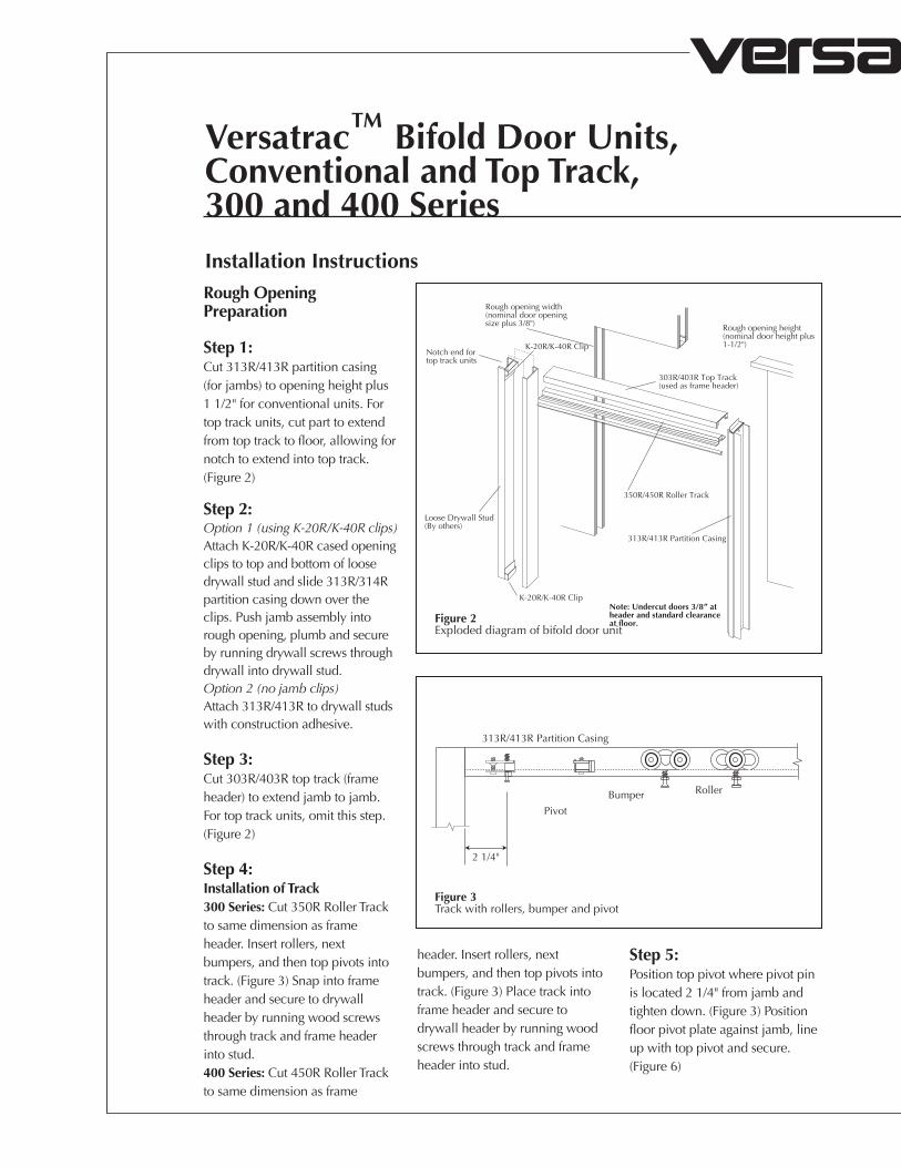
Versatrac™ Bifold Door Units,Conventional and Top Track,300 and 400 SeriesInstallation InstructionsRough Opening Preparation
Step 1:Cut 313R/413R partition casing (for jambs) to opening height plus 1 1/2" for conventional units. For top track units, cut part to extend from top track to floor, allowing for notch to extend into top track. (Figure 2)
Step 2:Option 1 (using K-20R/K-40R clips)Attach K-20R/K-40R cased opening clips to top and bottom of loose drywall stud and slide 313R/314R partition casing down over the clips. Push jamb assembly into rough opening, plumb and secure by running drywall screws through drywall into drywall stud.Option 2 (no jamb clips)Attach 313R/413R to drywall studs with construction adhesive.
Step 3:Cut 303R/403R top track (frame header) to extend jamb to jamb. For top track units, omit this step. (Figure 2)
Step 4:Installation of Track300 Series: Cut 350R Roller Track to same dimension as frame header. Insert rollers, next bumpers, and then top pivots into track. (Figure 3) Snap into frame header and secure to drywall header by running wood screws through track and frame header into stud.400 Series: Cut 450R Roller Track to same dimension as frame
Loose Drywall Stud(By others)
350R/450R Roller Track
313R/413R Partition Casing
303R/403R Top Track(used as frame header)
K-20R/K-40R Clip
K-20R/K-40R ClipNotch end fortop track units
Rough opening height(nominal door height plus 1-1/2")
Rough opening width(nominal door opening size plus 3/8")
Note: Undercut doors 3/8” at header and standard clearance at floor.Figure 2
Exploded diagram of bifold door unit
2 1/4"
Pivot
313R/413R Partition Casing
Bumper Roller
header. Insert rollers, next bumpers, and then top pivots into track. (Figure 3) Place track into frame header and secure to drywall header by running wood screws through track and frame header into stud.
Step 5:Position top pivot where pivot pin is located 2 1/4" from jamb and tighten down. (Figure 3) Position floor pivot plate against jamb, line up with top pivot and secure. (Figure 6)
Figure 3Track with rollers, bumper and pivot
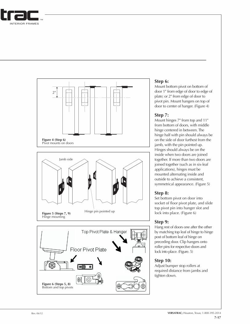
Rev. 06/12 VERSATRAC; Houston, Texas; 1-800-395-2014
INTERIOR FRAMES
TM
7-17
2"
Hinge pin pointed up
Jamb side
Step 6:Mount bottom pivot on bottom of door 1" from edge of door to edge of plate; or 2" from edge of door to pivot pin. Mount hangers on top of door to center of hanger. (Figure 4)
Step 7:Mount hinges 7" from top and 11" from bottom of doors, with middle hinge centered in between. The hinge half with pin should always be on the side of door furthest from the jamb, with the pin pointed up. Hinges should always be on the inside when two doors are joined together. If more than two doors are joined together (such as in six-leaf applications), hinges must be mounted alternating inside and outside to achieve a consistent, symmetrical appearance. (Figure 5)
Step 8:Set bottom pivot on door into socket of floor pivot plate, and slide top pivot pin into hanger slot and lock into place. (Figure 6)
Step 9:Hang rest of doors one after the other by matching top leaf of hinge to hinge post of bottom leaf of hinge on preceding door. Clip hangers onto roller pins for respective doors and lock into place. (Figure. 5)
Step 10:Adjust bumper stop rollers at required distance from jambs and tighten down.
Figure 4 (Step 6)Pivot mounts on doors
Figure 5 (Steps 7, 9)Hinge mounting
Figure 6 (Steps 5, 8)Bottom and top pivots
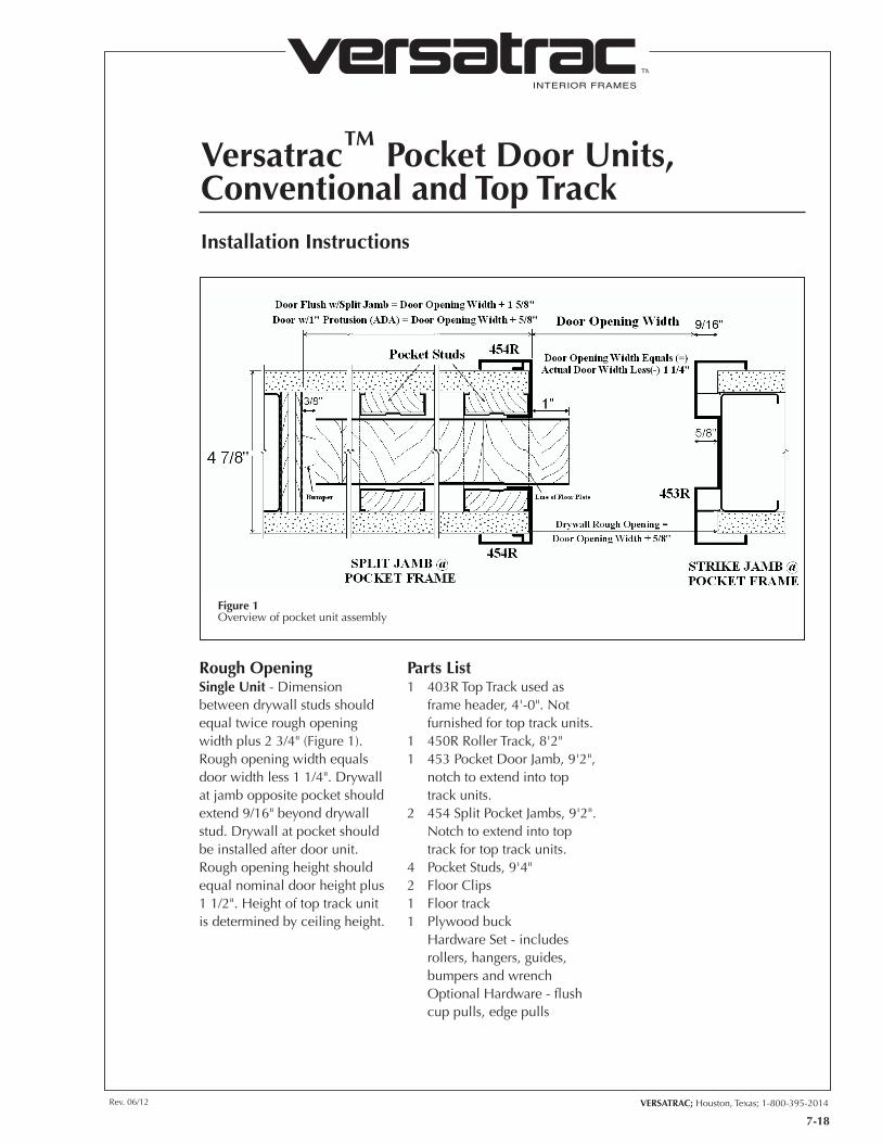
INTERIOR FRAMES
TM
VERSATRAC; Houston, Texas; 1-800-395-2014Rev. 06/12
Versatrac™ Pocket Door Units, Conventional and Top Track
7-18
Installation Instructions
Rough OpeningSingle Unit - Dimension between drywall studs should equal twice rough opening width plus 2 3/4" (Figure 1). Rough opening width equals door width less 1 1/4". Drywall at jamb opposite pocket should extend 9/16" beyond drywall stud. Drywall at pocket should be installed after door unit. Rough opening height should equal nominal door height plus 1 1/2". Height of top track unit is determined by ceiling height.
Parts List1 403R Top Track used as
frame header, 4'-0". Not furnished for top track units.
1 450R Roller Track, 8'2"1 453 Pocket Door Jamb, 9'2",
notch to extend into top track units.
2 454 Split Pocket Jambs, 9'2". Notch to extend into top track for top track units.
4 Pocket Studs, 9'4"2 Floor Clips1 Floor track1 Plywood buck Hardware Set - includes
rollers, hangers, guides, bumpers and wrench
Optional Hardware - flush cup pulls, edge pulls
Figure 1Overview of pocket unit assembly
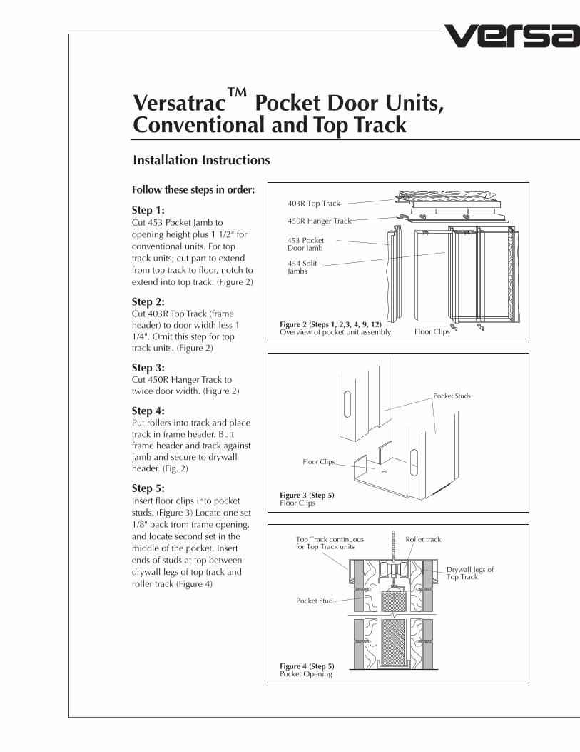
INTERIOR FRAMES
TM
Versatrac™ Pocket Door Units, Conventional and Top TrackInstallation Instructions
403R Top Track
450R Hanger Track
Floor Clips
453 PocketDoor Jamb
454 SplitJambs
Pocket Studs
Floor Clips
Pocket Stud
Top Track continuousfor Top Track units
Roller track
Drywall legs ofTop Track
Follow these steps in order:
Step 1:Cut 453 Pocket Jamb to opening height plus 1 1/2" for conventional units. For top track units, cut part to extend from top track to floor, notch to extend into top track. (Figure 2)
Step 2:Cut 403R Top Track (frame header) to door width less 1 1/4". Omit this step for top track units. (Figure 2)
Step 3:Cut 450R Hanger Track to twice door width. (Figure 2)
Step 4:Put rollers into track and place track in frame header. Butt frame header and track against jamb and secure to drywall header. (Fig. 2)
Step 5:Insert floor clips into pocket studs. (Figure 3) Locate one set 1/8" back from frame opening, and locate second set in the middle of the pocket. Insert ends of studs at top between drywall legs of top track and roller track (Figure 4)
Figure 2 (Steps 1, 2,3, 4, 9, 12)Overview of pocket unit assembly
Figure 3 (Step 5)Floor Clips
Figure 4 (Step 5)Pocket Opening
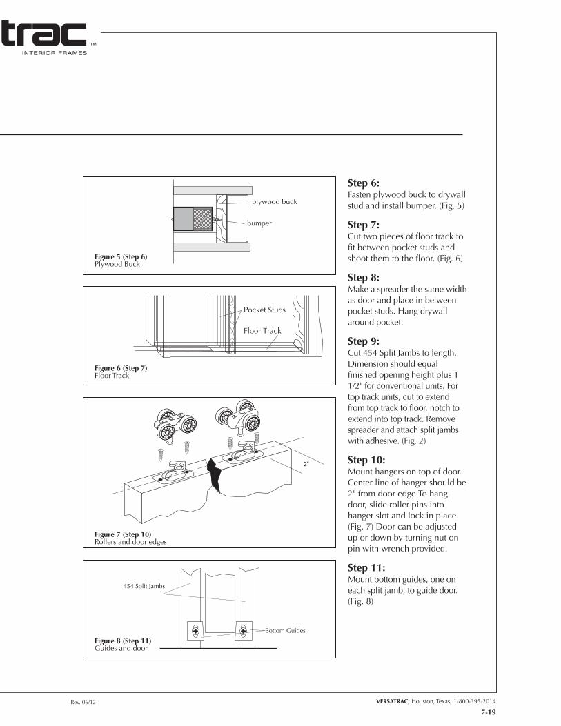
Rev. 06/12 VERSATRAC; Houston, Texas; 1-800-395-2014
INTERIOR FRAMES
TM
7-19
plywood buck
bumper
Pocket Studs
Floor Track
2"
Bottom Guides
454 Split Jambs
Step 6:Fasten plywood buck to drywall stud and install bumper. (Fig. 5)
Step 7:Cut two pieces of floor track to fit between pocket studs and shoot them to the floor. (Fig. 6)
Step 8:Make a spreader the same width as door and place in between pocket studs. Hang drywall around pocket.
Step 9:Cut 454 Split Jambs to length. Dimension should equal finished opening height plus 1 1/2" for conventional units. For top track units, cut to extend from top track to floor, notch to extend into top track. Remove spreader and attach split jambs with adhesive. (Fig. 2)
Step 10:Mount hangers on top of door. Center line of hanger should be 2" from door edge.To hang door, slide roller pins into hanger slot and lock in place. (Fig. 7) Door can be adjusted up or down by turning nut on pin with wrench provided.
Step 11:Mount bottom guides, one on each split jamb, to guide door. (Fig. 8)
Figure 5 (Step 6)Plywood Buck
Figure 6 (Step 7)Floor Track
Figure 7 (Step 10)Rollers and door edges
Figure 8 (Step 11)Guides and door
INTERIOR FRAMES
TM
VERSATRAC; Houston, Texas; 1-800-395-2014Rev. 06/12
Versatrac™ Conventional, FreestandingFrame with Full Length Sidelite One Side
7-20
Installation Instructions
Parts List1 RAF-2 Hinge Jamb1 RCH-3QL Strike Jamb2 Snap-on Door Stops1 RCH-4 Snap-in Header1 311R/411R H-Mullion
(used as header)*2 307R/407R Glazing Snap-in
Members, nominal lengths*1 306R/406R Glazing Jamb
nominal length*1 308R/408R Glazing Sill with
309R/409R and 309RL/409RL Glazing Snaps, nominal lengths
1 K-10 angle clip1 K-16H head clip for strike1 K-16S foot clip for strike*6 K-56B clips*20 T-10 TEK screws Glazing Vinyl* Quantities change if intermediate
mullions are added.
Rough OpeningRough opening should equal sum of nominal door (finished opening) size, glass opening size, 1 1/2" for each mullion, and 1 1/2" for jamb clearance. Rough opening height should equal nominal door height plus 3/4" to 1". Drywall stud should be set back 2 1/4" from rough opening on door jamb side. Drywall stud at glazing jamb should be even with drywall edge.
Follow these steps in order. See Typical Connections and Conventional Freestanding Sidelight Connections for diagrams.
Step 1:For frames with extra-length jambs, cut pieces to desired length. (NOTE: Strike jamb between door and glass should be 1 1/2" shorter than hinge jamb, and will be notched to accommodate the stop portion of the snap-in header.)
Step 2:Insert jamb for drywall side of frame into wall, plumb, and secure by screwing through drywall into backer stud with drywall screws.
Step 3:Cut 306R/406R glazing jamb to desired length. Mill end to allow it to extend beyond drywall to height of door jamb. (Figure 3-F)
Step 4:Cut 311R/411R H-mullion to extend between door jamb and glazing jamb. Secure by screwing through rib of H-mullion into drywall header with drywall screws. Attach jamb to H-mullion. (Figure 3-F)
Step 5:Snap in RCH-4 Header
Step 6:Insert K-16S foot clip and K-16H head clip into strike jamb. Horizontal leg of clip should be pointing toward glass side. (Figures 1-G and 1-I) Secure top and bottom with TEK screws. Snap in 307R/407R glazing channel.
Step 7:For intermediate mullions, cut 306R/406R glazing mullion to length. Secure top and bottom with K-56B clips. (Figures 3-E and 1-C) 306R/406R glazing mullion may also be secured to the floor with a K-16S clip. Snap in 307R/407R glazing channel.
Step 8Cut 307R/407R glazing channel to extend across glass opening at head and snap in.
Step 9:Cut 308R/408R glazing sill and 309R/409R and 309RL/409RL glazing snaps to extend across the bottom of glass opening. Block underneath (blocking by others) and shoot glazing sill to floor. (Figure 1-D) Leave glazing snaps loose at opening until glass is installed.
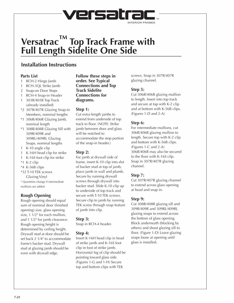
INTERIOR FRAMES
TM
Versatrac™ Top Track Frame withFull Length Sidelite One Side
7-21
Installation Instructions
Parts List1 RCH-2 Hinge Jamb1 RCH-3QL Strike Jamb2 Snap-on Door Stops1 RCH-4 Snap-in Header1 303R/403R Top Track
(already installed)*2 307R/407R Glazing Snap-in
Members, nominal lengths*1 306R/406R Glazing Jamb,
nominal length*1 308R/408R Glazing Sill with
309R/409R and 309RL/409RL Glazing Snaps, nominal lengths
1 K-10 angle clip1 K-16H head clip for strike1 K-16S foot clip for strike*1 K-2 clip*4 K-56B clips*32 T-10 TEK screws Glazing Vinyl* Quantities change if intermediate
mullions are added.
Rough OpeningRough opening should equal sum of nominal door (finished opening) size, glass opening size, 1 1/2" for each mullion, and 1 1/2" for jamb clearance. Rough opening height is determined by ceiling height. Drywall stud at door should be set back 2 1/4" to accommodate frame’s backer stud. Drywall stud at glazing jamb should be even with drywall edge.
Follow these steps in order. See Typical Connections and Top Track Sidelite Connections for diagrams.
Step 1:Cut extra-length jambs to extend from underside of top track to floor. (NOTE: Strike jamb between door and glass will be notched to accommodate the stop portion of the snap-in header.)
Step 2:For jamb at drywall side of frame, insert K-10 clip into slot of backer stud at top of jamb, place jamb in wall and plumb. Secure by running drywall screws through drywall into backer stud. Slide K-10 clip up to underside of top track and secure with T-10 TEK screws. Secure clip to jamb by running TEK screw through snap feature of jamb into clip.
Step 3:Snap in RCH-4 header.
Step 4:Insert K-16H head clip in head of strike jamb and K-16S foot clip in foot of strike jamb. Horizontal leg of clip should be pointing toward glass side. (Figures 1-G and 1-H) Secure top and bottom clips with TEK
screws. Snap in 307R/407R glazing channel.
Step 5:Cut 306R/406R glazing mullion to length. Insert into top track and secure at top with K-2 clip and at bottom with K-56B clips. (Figures 1-D and 2-A)
Step 6:For intermediate mullions, cut 306R/406R glazing mullion to length. Secure top with K-2 clip and bottom with K-56B clips. (Figures 1-C and 2-A) 306R/406R may also be secured to the floor with K-16S clip. Snap in 307R/407R glazing channel.
Step 7:Cut 307R/407R glazing channel to extend across glass opening at head and snap in.
Step 9:Cut 308R/408R glazing sill and 309R/409R and 309RL/409RL glazing snaps to extend across the bottom of glass opening. Block underneath (blocking by others) and shoot glazing sill to floor. (Figure 1-D) Leave glazing snaps loose at opening until glass is installed.
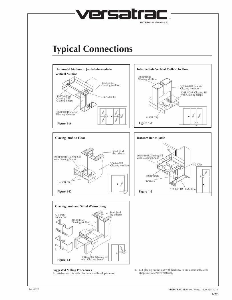
INTERIOR FRAMES
TM
VERSATRAC; Houston, Texas; 1-800-395-2014Rev. 06/12
7-22
Typical Connections
306R/406RGlazing Mullion
K-56B Clip308M/408MGlazing Sill/Glazing Snaps
307R/407R Snap-inGlazing Member
Figure 1-A
308R/408R Glazing Sillwith Glazing Snaps
307R/407R Snap-in Glazing Member
306R/406RGlazing Mullion
K-56B Clip
Intermediate Vertical Mullion to Floor
Figure 1-C
Steel Stud(by others)
306R/406RGlazing Mullion
308R/408R Glazing Sillwith Glazing Snaps
K-56B Clip
Glazing Jamb to Floor
Figure 1-D311R/411R H-Mullion
RCH-4A
308R/408RGlazing Sillwith Glazing Snaps
K-2 Clip
305R/405R
Transom Bar to Jamb
Figure 1-E
308R/408R Glazing Sillwith Glazing Snaps
Steel Stud(by others)
306R/406RGlazing Mullion
A. 13/16"Knock out
B.
Glazing Jamb and Sill at Wainscoting
Figure 1-F
Horizontal Mullion to Jamb/Intermediate
Vertical Mullion
Suggested Milling ProceduresA. Make saw cuts with chop saw and break pieces off.
B. Cut glazing pocket out with hacksaw or cut continually with chop saw to remove material.

INTERIOR FRAMES
TM
7-23
Typical Connections
Door Jamb
K-16S Clip
Figure 1-G
311R/411R H-mullion
307R/407R Snap-inGlazing Member
K-16H Clip
Door Jamb
H-Mullion Header to Sidelite Jamb
(using K-16H Clip)
Figure 1-I
303R/403R Top Track
K-16H Clip
Door Jamb
307R/407R Snap-inGlazing Member
Figure 1-H
307R/407R Snap-inGlazing Member
306R/406RGlazing Mullion
308R/408R Glazing Sillwith Glazing Snaps
K-56B Clips
A. 13/16"Knock Out
B.
1/2"
Intermediate Vertical Mullion to Sill
Figure 1-J
Sidelite Jamb to Floor (using K-16S Clip) Top Track to Sidelite Jamb (using K-16H Clip)
Suggested Milling ProceduresA. Make saw cuts with chop saw and break pieces off.
B. Cut glazing pocket out with hacksaw or cut continually with chop saw to remove material.
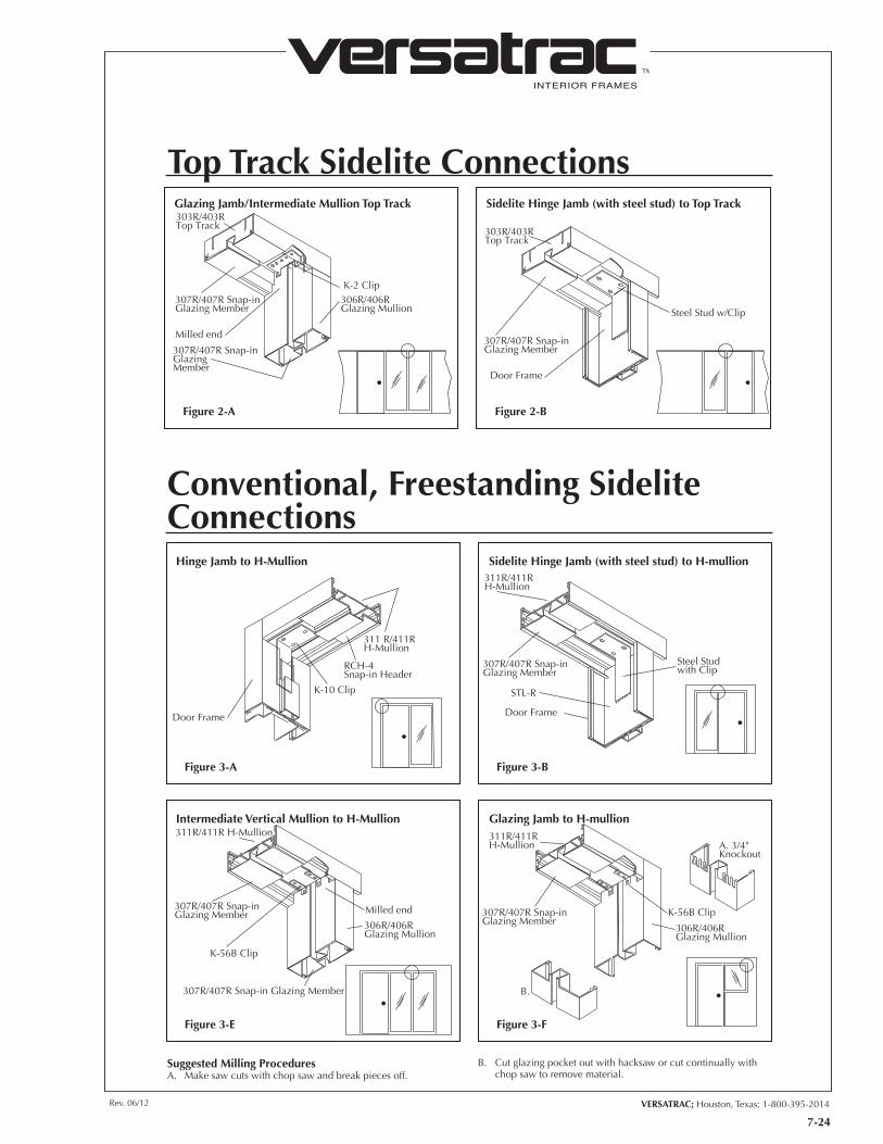
INTERIOR FRAMES
TM
VERSATRAC; Houston, Texas; 1-800-395-2014Rev. 06/12
7-24
Top Track Sidelite Connections
K-2 Clip307R/407R Snap-inGlazing Member
Milled end
303R/403RTop Track
306R/406RGlazing Mullion
307R/407R Snap-inGlazing Member
Glazing Jamb/Intermediate Mullion Top Track
Figure 2-A
Steel Stud w/Clip
307R/407R Snap-inGlazing Member
Door Frame
303R/403RTop Track
Sidelite Hinge Jamb (with steel stud) to Top Track
Figure 2-B
Conventional, Freestanding Sidelite Connections
RCH-4Snap-in Header
311 R/411RH-Mullion
Door Frame
K-10 Clip
Figure 3-A
311R/411RH-Mullion
307R/407R Snap-inGlazing Member
Door Frame
Steel Studwith Clip
STL-R
Figure 3-B
311R/411R H-Mullion
307R/407R Snap-inGlazing Member
307R/407R Snap-in Glazing Member
306R/406RGlazing Mullion
Milled end
K-56B Clip
Intermediate Vertical Mullion to H-Mullion
Figure 3-E
311R/411RH-Mullion
307R/407R Snap-inGlazing Member
K-56B Clip
306R/406RGlazing Mullion
B.
A. 3/4"Knockout
Glazing Jamb to H-mullion
Figure 3-F
Hinge Jamb to H-Mullion Sidelite Hinge Jamb (with steel stud) to H-mullion
Suggested Milling ProceduresA. Make saw cuts with chop saw and break pieces off.
B. Cut glazing pocket out with hacksaw or cut continually with chop saw to remove material.
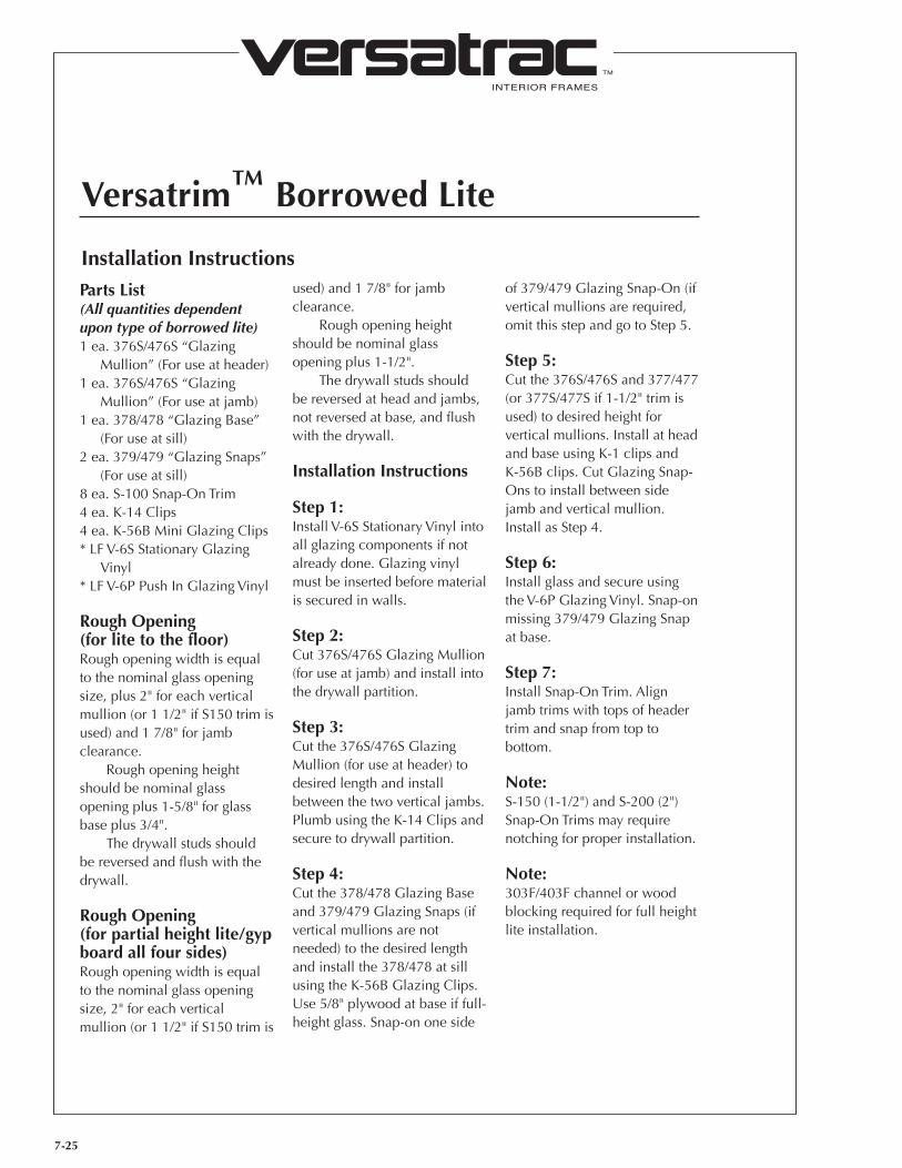
INTERIOR FRAMES
TM
7-25
Versatrim™ Borrowed Lite
Installation InstructionsParts List(All quantities dependent upon type of borrowed lite)1 ea. 376S/476S “Glazing
Mullion” (For use at header)1 ea. 376S/476S “Glazing
Mullion” (For use at jamb)1 ea. 378/478 “Glazing Base”
(For use at sill)2 ea. 379/479 “Glazing Snaps”
(For use at sill)8 ea. S-100 Snap-On Trim4 ea. K-14 Clips4 ea. K-56B Mini Glazing Clips* LF V-6S Stationary Glazing
Vinyl* LF V-6P Push In Glazing Vinyl
Rough Opening (for lite to the floor)Rough opening width is equal to the nominal glass opening size, plus 2" for each vertical mullion (or 1 1/2" if S150 trim is used) and 1 7/8" for jamb clearance.
Rough opening height should be nominal glass opening plus 1-5/8" for glass base plus 3/4".
The drywall studs should be reversed and flush with the drywall.
Rough Opening (for partial height lite/gyp board all four sides)Rough opening width is equal to the nominal glass opening size, 2" for each vertical mullion (or 1 1/2" if S150 trim is
used) and 1 7/8" for jamb clearance.
Rough opening height should be nominal glass opening plus 1-1/2".
The drywall studs should be reversed at head and jambs, not reversed at base, and flush with the drywall.
Installation Instructions
Step 1:Install V-6S Stationary Vinyl into all glazing components if not already done. Glazing vinyl must be inserted before material is secured in walls.
Step 2:Cut 376S/476S Glazing Mullion (for use at jamb) and install into the drywall partition.
Step 3:Cut the 376S/476S Glazing Mullion (for use at header) to desired length and install between the two vertical jambs. Plumb using the K-14 Clips and secure to drywall partition.
Step 4:Cut the 378/478 Glazing Base and 379/479 Glazing Snaps (if vertical mullions are not needed) to the desired length and install the 378/478 at sill using the K-56B Glazing Clips. Use 5/8" plywood at base if full-height glass. Snap-on one side
of 379/479 Glazing Snap-On (if vertical mullions are required, omit this step and go to Step 5.
Step 5:Cut the 376S/476S and 377/477 (or 377S/477S if 1-1/2" trim is used) to desired height for vertical mullions. Install at head and base using K-1 clips and K-56B clips. Cut Glazing Snap-Ons to install between side jamb and vertical mullion. Install as Step 4.
Step 6:Install glass and secure using the V-6P Glazing Vinyl. Snap-on missing 379/479 Glazing Snap at base.
Step 7:Install Snap-On Trim. Align jamb trims with tops of header trim and snap from top to bottom.
Note:S-150 (1-1/2") and S-200 (2")Snap-On Trims may require notching for proper installation.
Note:303F/403F channel or wood blocking required for full height lite installation.

INTERIOR FRAMES
TM
VERSATRAC; Houston, Texas; 1-800-395-2014Rev. 06/12
7-26
Versatrim™ Frame with Sidelite (3/8" x 1" Snap-On Trim)
Installation InstructionsParts List(All quantities dependent upon type of sidelite)1 ea. VT-1 Header1 ea. VT-2 Hinge Jamb1 ea. VT-3 Strike Jamb1 ea. 376S/476S “Glazing
Mullion” (For use at header)1 ea. 376S/476S “Glazing
Mullion” (For use at jamb)1 ea. 377/477 “Glazing Snap-in”
(For use at strike)1 ea. 378/478 “Glazing Base”
(For use at sill)2 ea. 379/479 “Glazing Snaps”
(For use at sill)8 ea. S-100 Snap-On Trim4 ea. K-14 Clips2 ea. K-1 Clips4 ea. K-56B Mini-Clipsl.f. V-6S Stationary Glazing Vinyll.f. V-6P Push-in Glazing Vinyl1 ea. K-16V Floor Clip
Rough OpeningRough opening width is equal to the nominal door (finished opening size) size, glass opening size, 2" for each vertical mullion and 1 1/2" for jamb clearance.
Rough opening height should be nominal door (finished opening) height plus 3/4" for full height glass.
The drywall studs should be reversed and flush with the drywall at head and jambs.
If less than full height at, drywall stud at base should not be reversed and should be flush with drywall.
Installation InstructionsStep 1:Insert VT-1 Header into place.
Step 2:For jambs furnished with extra length, measure distance from header and cut jambs to desired length.
Step 3:Insert VT-2 hinge jamb tabs into header slots and push jamb into place.
Step 4:Plumb VT-2 hinge jamb and attach to wall using 1 1/4" drywall screws placed into pre-drilled holes along frame edge. Make sure that frame is not twisted in wall when fastening.
Step 5:Pull VT-1 Header down snug to drywall. Square with hinge jamb using K-14 clips.
Step 6:**Install V-6S Glazing Vinyl into all glazing components. Vinyl must be installed before glazing material is secured in walls.
Step 7:Set VT-3 strike jamb to door opening width and secure to floor with K-16V clip. Cut 377/477 Glazing Snap-In to desired length and slide into the back of VT-3 strike jamb.
Cut 376S/476S Glazing Jamb to desired height and install in drywall partition opposite the hinge jamb. Square using K-14 clips and secure.
Step 8:Cut 376S/476S Glazing Jamb (for use at header) to desired length and install level with VT-1 door header. Fasten to door header using K-1 clips (opposite end of glazing header should receive the K-14 Clip as detailed in Step 7.)
Step 9:Cut the 378/478 Glazing Base to desired length and secure to floor using wood blocking (NIC). Attach to sidelite strike jamb and glazing mullion using 2 K-56B clips per side. Cut 379/479 Glazing Snaps to desired lengths. Install one side of 379/479 Glazing Snap; other piece to be installed after glass is installed.
Step 10:Install glass and secure using V-6P Glazing Vinyl and 379/479 Glazing Snap.
Step 11:Install S-100 Snap-On Trim. Trim should be installed after doors are hung and final jamb adjustments are made. Align jamb trims with tops of header trim and snap from top to bottom.
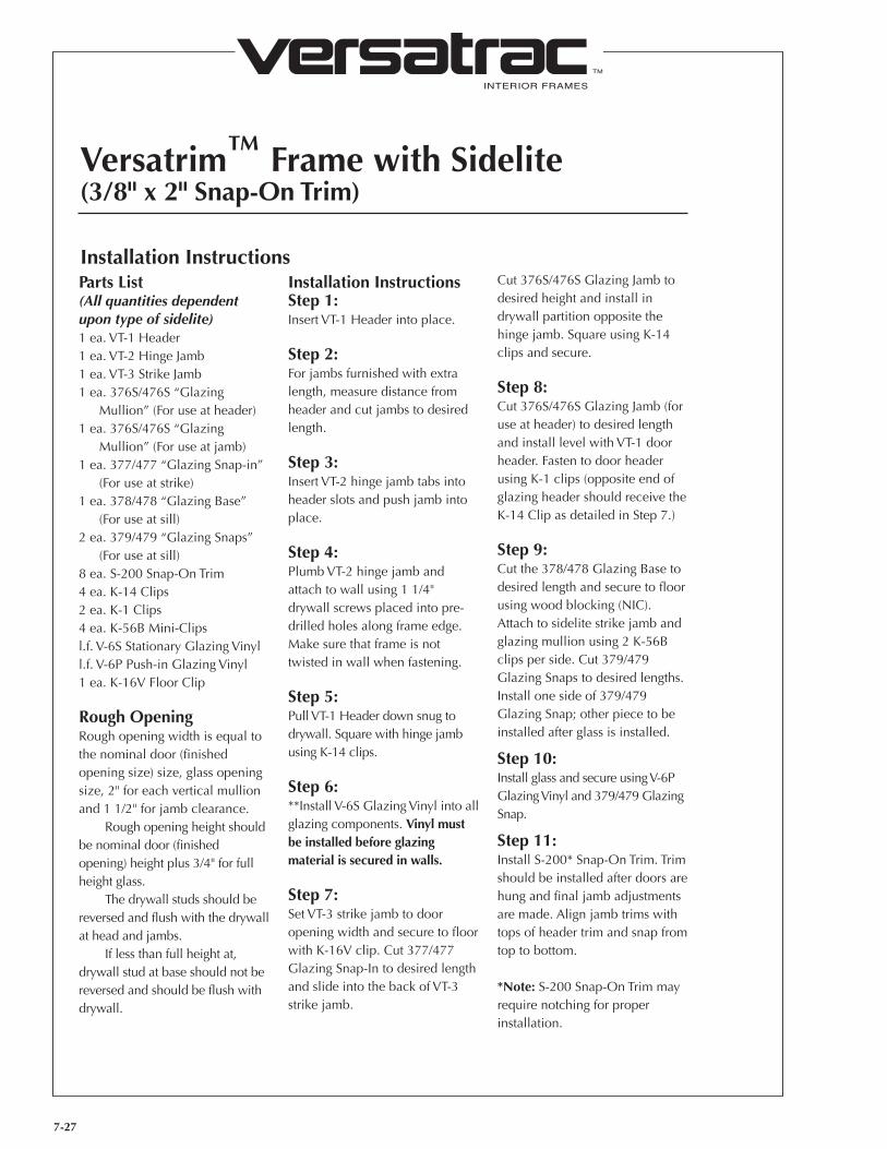
INTERIOR FRAMES
TM
7-27
Versatrim™ Frame with Sidelite (3/8" x 2" Snap-On Trim)
Installation InstructionsParts List(All quantities dependent upon type of sidelite)1 ea. VT-1 Header1 ea. VT-2 Hinge Jamb1 ea. VT-3 Strike Jamb1 ea. 376S/476S “Glazing
Mullion” (For use at header)1 ea. 376S/476S “Glazing
Mullion” (For use at jamb)1 ea. 377/477 “Glazing Snap-in”
(For use at strike)1 ea. 378/478 “Glazing Base”
(For use at sill)2 ea. 379/479 “Glazing Snaps”
(For use at sill)8 ea. S-200 Snap-On Trim4 ea. K-14 Clips2 ea. K-1 Clips4 ea. K-56B Mini-Clipsl.f. V-6S Stationary Glazing Vinyll.f. V-6P Push-in Glazing Vinyl1 ea. K-16V Floor Clip
Rough OpeningRough opening width is equal to the nominal door (finished opening size) size, glass opening size, 2" for each vertical mullion and 1 1/2" for jamb clearance.
Rough opening height should be nominal door (finished opening) height plus 3/4" for full height glass.
The drywall studs should be reversed and flush with the drywall at head and jambs.
If less than full height at, drywall stud at base should not be reversed and should be flush with drywall.
Installation InstructionsStep 1:Insert VT-1 Header into place.
Step 2:For jambs furnished with extra length, measure distance from header and cut jambs to desired length.
Step 3:Insert VT-2 hinge jamb tabs into header slots and push jamb into place.
Step 4:Plumb VT-2 hinge jamb and attach to wall using 1 1/4" drywall screws placed into pre-drilled holes along frame edge. Make sure that frame is not twisted in wall when fastening.
Step 5:Pull VT-1 Header down snug to drywall. Square with hinge jamb using K-14 clips.
Step 6:**Install V-6S Glazing Vinyl into all glazing components. Vinyl must be installed before glazing material is secured in walls.
Step 7:Set VT-3 strike jamb to door opening width and secure to floor with K-16V clip. Cut 377/477 Glazing Snap-In to desired length and slide into the back of VT-3 strike jamb.
Cut 376S/476S Glazing Jamb to desired height and install in drywall partition opposite the hinge jamb. Square using K-14 clips and secure.
Step 8:Cut 376S/476S Glazing Jamb (for use at header) to desired length and install level with VT-1 door header. Fasten to door header using K-1 clips (opposite end of glazing header should receive the K-14 Clip as detailed in Step 7.)
Step 9:Cut the 378/478 Glazing Base to desired length and secure to floor using wood blocking (NIC). Attach to sidelite strike jamb and glazing mullion using 2 K-56B clips per side. Cut 379/479 Glazing Snaps to desired lengths. Install one side of 379/479 Glazing Snap; other piece to be installed after glass is installed.
Step 10:Install glass and secure using V-6P Glazing Vinyl and 379/479 Glazing Snap.
Step 11:Install S-200* Snap-On Trim. Trim should be installed after doors are hung and final jamb adjustments are made. Align jamb trims with tops of header trim and snap from top to bottom.
*Note: S-200 Snap-On Trim may require notching for proper installation.
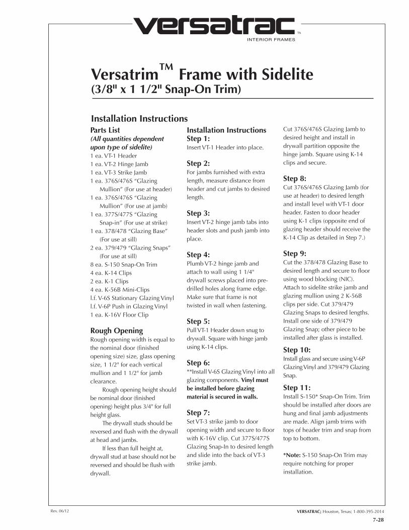
INTERIOR FRAMES
TM
VERSATRAC; Houston, Texas; 1-800-395-2014Rev. 06/12
7-28
Versatrim™ Frame with Sidelite (3/8" x 1 1/2" Snap-On Trim)
Installation InstructionsParts List(All quantities dependent upon type of sidelite)1 ea. VT-1 Header1 ea. VT-2 Hinge Jamb1 ea. VT-3 Strike Jamb1 ea. 376S/476S “Glazing
Mullion” (For use at header)1 ea. 376S/476S “Glazing
Mullion” (For use at jamb)1 ea. 377S/477S “Glazing
Snap-in” (For use at strike)1 ea. 378/478 “Glazing Base”
(For use at sill)2 ea. 379/479 “Glazing Snaps”
(For use at sill)8 ea. S-150 Snap-On Trim4 ea. K-14 Clips2 ea. K-1 Clips4 ea. K-56B Mini-Clipsl.f. V-6S Stationary Glazing Vinyll.f. V-6P Push in Glazing Vinyl1 ea. K-16V Floor Clip
Rough OpeningRough opening width is equal to the nominal door (finished opening size) size, glass opening size, 1 1/2" for each vertical mullion and 1 1/2" for jamb clearance.
Rough opening height should be nominal door (finished opening) height plus 3/4" for full height glass.
The drywall studs should be reversed and flush with the drywall at head and jambs.
If less than full height at, drywall stud at base should not be reversed and should be flush with drywall.
Installation InstructionsStep 1:Insert VT-1 Header into place.
Step 2:For jambs furnished with extra length, measure distance from header and cut jambs to desired length.
Step 3:Insert VT-2 hinge jamb tabs into header slots and push jamb into place.
Step 4:Plumb VT-2 hinge jamb and attach to wall using 1 1/4" drywall screws placed into pre-drilled holes along frame edge. Make sure that frame is not twisted in wall when fastening.
Step 5:Pull VT-1 Header down snug to drywall. Square with hinge jamb using K-14 clips.
Step 6:**Install V-6S Glazing Vinyl into all glazing components. Vinyl must be installed before glazing material is secured in walls.
Step 7:Set VT-3 strike jamb to door opening width and secure to floor with K-16V clip. Cut 377S/477S Glazing Snap-In to desired length and slide into the back of VT-3 strike jamb.
Cut 376S/476S Glazing Jamb to desired height and install in drywall partition opposite the hinge jamb. Square using K-14 clips and secure.
Step 8:Cut 376S/476S Glazing Jamb (for use at header) to desired length and install level with VT-1 door header. Fasten to door header using K-1 clips (opposite end of glazing header should receive the K-14 Clip as detailed in Step 7.)
Step 9:Cut the 378/478 Glazing Base to desired length and secure to floor using wood blocking (NIC). Attach to sidelite strike jamb and glazing mullion using 2 K-56B clips per side. Cut 379/479 Glazing Snaps to desired lengths. Install one side of 379/479 Glazing Snap; other piece to be installed after glass is installed.
Step 10:Install glass and secure using V-6P Glazing Vinyl and 379/479 Glazing Snap.
Step 11:Install S-150* Snap-On Trim. Trim should be installed after doors are hung and final jamb adjustments are made. Align jamb trims with tops of header trim and snap from top to bottom.
*Note: S-150 Snap-On Trim may require notching for proper installation.
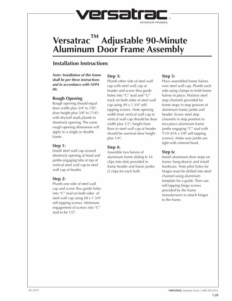
INTERIOR FRAMES
TM
VERSATRAC; Houston, Texas; 1-800-395-2014Rev. 06/12
7-29
Versatrac™ Adjustable 90-Minute Aluminum Door Frame AssemblyInstallation Instructions
Note: Installation of this frame shall be per these instructions and in accordance with NFPA 80.
Rough OpeningRough opening should equal door width plus 3/4" to 7/8"; door height plus 3/8" to 7/16"; with drywall studs plumb to sheetrock opening. The same rough opening dimension will apply to a single or double frame.
Step 1:Install steel wall cap around sheetrock opening at head and jambs engaging tabs at top of vertical steel wall cap to steel wall cap at header.
Step 2:Plumb one side of steel wall cap and screw thru guide holes into “C” stud on both sides of steel wall cap using #8 x 1 3/4" self-tapping screws. Minimum engagement of screws into “C” stud to be 1/2".
Step 3:Plumb other side of steel wall cap with steel wall cap at header and screw thru guide holes into “C” stud and “U” track on both sides of steel wall cap using #9 x 1 3/4" self-tapping screws. Note opening width from vertical wall cap to vertical wall cap should be door width plus 1/2"; height from floor to steel wall cap at header should be nominal door height plus 1/4".
Step 4:Assemble two halves of aluminum frame sliding K-14 clips into slots provided in frame header and frame jambs (2 clips for each half).
Step 5:Place assembled frame halves over steel wall cap. Plumb each side using clamps to hold frame halves in place. Position steel stop channels provided for frame stops in stop grooves of aluminum frame jambs and header. Screw steel stop channels in stop position to two-piece aluminum frame jambs engaging “C” stud with T-10 (#16 x 5/8" self-tapping screws). Make sure jambs are tight with mitered head.
Step 6:Install aluminum door stops on frame; hang door(s) and install hardware. Note pilot holes for hinges must be drilled into steel channel using aluminum template for a guide. Then use self-tapping hinge screws provided by the frame manufacturer to attach hinges to the frame.
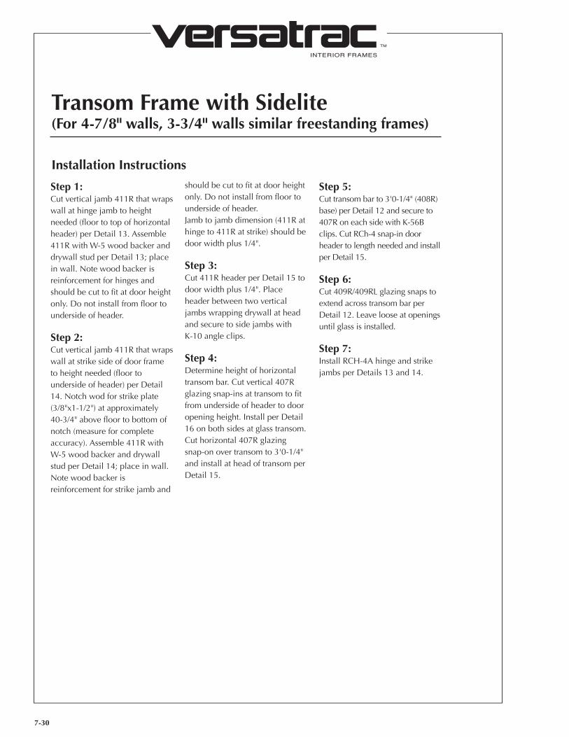
7-30
INTERIOR FRAMES
TM
Transom Frame with Sidelite (For 4-7/8" walls, 3-3/4" walls similar freestanding frames)
Installation Instructions
Step 1:Cut vertical jamb 411R that wraps wall at hinge jamb to height needed (floor to top of horizontal header) per Detail 13. Assemble 411R with W-5 wood backer and drywall stud per Detail 13; place in wall. Note wood backer is reinforcement for hinges and should be cut to fit at door height only. Do not install from floor to underside of header.
Step 2:Cut vertical jamb 411R that wraps wall at strike side of door frame to height needed (floor to underside of header) per Detail 14. Notch wod for strike plate (3/8"x1-1/2") at approximately 40-3/4" above floor to bottom of notch (measure for complete accuracy). Assemble 411R with W-5 wood backer and drywall stud per Detail 14; place in wall. Note wood backer is reinforcement for strike jamb and
should be cut to fit at door height only. Do not install from floor to underside of header.Jamb to jamb dimension (411R at hinge to 411R at strike) should be door width plus 1/4".
Step 3:Cut 411R header per Detail 15 to door width plus 1/4". Place header between two vertical jambs wrapping drywall at head and secure to side jambs with K-10 angle clips.
Step 4:Determine height of horizontal transom bar. Cut vertical 407R glazing snap-ins at transom to fit from underside of header to door opening height. Install per Detail 16 on both sides at glass transom. Cut horizontal 407R glazing snap-on over transom to 3'0-1/4" and install at head of transom per Detail 15.
Step 5:Cut transom bar to 3'0-1/4" (408R) base) per Detail 12 and secure to 407R on each side with K-56B clips. Cut RCh-4 snap-in door header to length needed and install per Detail 15.
Step 6:Cut 409R/409RL glazing snaps to extend across transom bar per Detail 12. Leave loose at openings until glass is installed.
Step 7:Install RCH-4A hinge and strike jambs per Details 13 and 14.
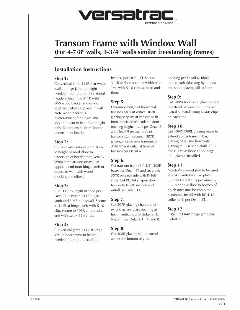
7-31
INTERIOR FRAMES
TM
VERSATRAC; Houston, Texas; 1-800-395-2014Rev. 06/12
Transom Frame with Window Wall (For 4-7/8" walls, 3-3/4" walls similar freestanding frames)
Installation Instructions
Step 1:Cut vertical jamb 311R that wraps wall at hinge jamb to height needed (floor to top of horizontal header). Assemble 311R with W-5 wood backer and drywall stud per Detail 2T; place in wall. Note wood backer is reinforcement for hinges and should be cut to fit at door height only. Do not install from floor to underside of header.
Step 2:Cut opposite vertical jamb 306R to height needed (floor to underside of header) per Detail 7. Wrap jamb around drywall at opposite end from hinge jamb or secure to wall with wood blocking (by others).
Step 3:Cut 311R to length needed per Detail 4 between 311R hinge jamb and 306R at drywall. Secure to 311R at hinge jamb with K-10 clip; secure to 306R at opposite end with two K-56B clips.
Step 4:Cut vertical jamb 311R at strike side of door frame to height needed (floor to underside of
header) per Detail 3T. Secure 311R at door opening width plus 1/4" with K-10 clips at head and floor.
Step 5:Determine height of horizontal transom bar. Cut vertical 307R glazing snap-ins at transom to fit from underside of header to door opening height. Install per Detail 8 and Detail 9 on each side of transom. Cut horizontal 307R glazing snap-in over transom to 3'0-1/4" and install at head of transom per Detail 4.
Step 6:Cut transom bar to 3'0-1/4" (308R base) per Detail 1T and secure to 307R on each side with K-56B clips. Cut RCH-4 snap-in door header to length needed and install per Detail 1T.
Step 7:Cut 307R glazing channels to extend across glass opening at head, verticals, and strike jamb. Snap-in per Details 3T, 4, and 8.
Step 8:Cut 308R glazing sill to extend across the bottom of glass
opening per Detail 6. Block underneath (blocking by others) and shoot glazing sill to floor.
Step 9:Cut 308M horizontal glazing mull to extend between mullions per Detail 5. Install using K-56B clips on each end.
Step 10:Cut 309R/309RL glazing snaps to extend across transom bar, glazing base, and horizontal glazing mull(s) per Details 1T, 5, and 6. Leave loose at openings until glass is installed.
Step 11:Notch W-5 wood stud to be used at strike jamb for strike plate (3-3/8"x1-1/2") at approximately 38-3/4" above floor to bottom of notch (measure for complete accuracy). Install with RCH-4A strike jamb per Detail 3T.
Step 12:Install RCH-4A hinge jamb per Detail 2T.
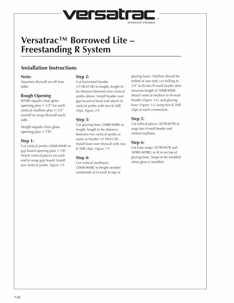
7-32
INTERIOR FRAMES
TM
Versatrac™ Borrowed Lite – Freestanding R System
Installation Instructions
Note:Assumes drywall on all four sides
Rough OpeningWidth equals clear glass opening plus 1-1/2" for each vertical mullion plus 1-1/2" overall to wrap drywall each side.
Height equals clear glass opening plus 1-7/8".
Step 1:Cut vertical jambs (306R/406R) to gyp board opening plus 1-7/8". Notch vertical pieces on each end to wrap gyp board. Install two vertical jambs. Figure 3-F.
Step 2:Cut horizontal header (311R/411R) to length; length to be distance between two vertical jambs above. Install header over gyp board at head and attach to vertical jambs with two K-56B clips. Figure 3-F.
Step 3:Cut glazing base (308R/408R) to length; length to be distance between two vertical jambs or same as header (311R/411R). Install base over drywall with two K-56B clips. Figure 1-F.
Step 4:Cut vertical mullion(s) (306R/406R) to height needed (underside of H-mull to top of
glazing base). Mullion should be milled at one end; cut milling to 3/4" to fit into H-mull header then measure length of 306R/406R. Attach vertical mullion to H-mull header (Figure 3-E) and glazing base (Figure 1-J) using two K-56B clips at each connection.
Step 5:Cut vertical pieces (307R/407R) to snap into H-mull header and vertical mullions.
Step 6:Cut base snaps (307R/407R and 309RL/409RL) to fit in on top of glazing base. Snaps to be installed when glass is installed.
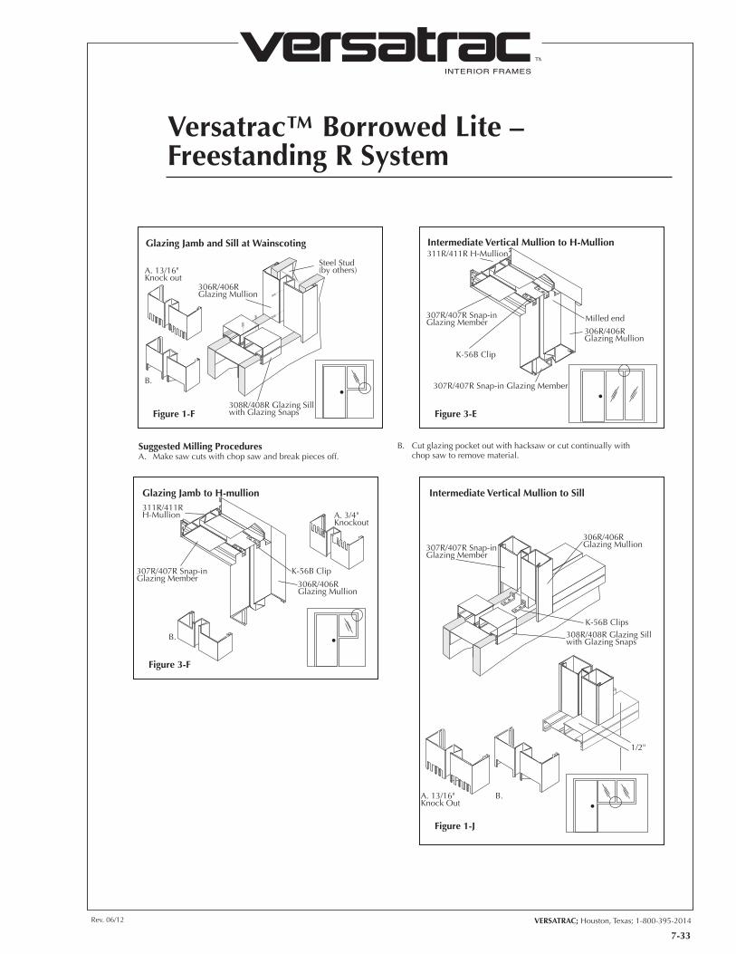
7-33
INTERIOR FRAMES
TM
VERSATRAC; Houston, Texas; 1-800-395-2014Rev. 06/12
Versatrac™ Borrowed Lite – Freestanding R System
307R/407R Snap-inGlazing Member
306R/406RGlazing Mullion
308R/408R Glazing Sillwith Glazing Snaps
K-56B Clips
A. 13/16"Knock Out
B.
1/2"
Intermediate Vertical Mullion to Sill
Figure 1-J
311R/411R H-Mullion
307R/407R Snap-inGlazing Member
307R/407R Snap-in Glazing Member
306R/406RGlazing Mullion
Milled end
K-56B Clip
Intermediate Vertical Mullion to H-Mullion
Figure 3-E
311R/411RH-Mullion
307R/407R Snap-inGlazing Member
K-56B Clip
306R/406RGlazing Mullion
B.
A. 3/4"Knockout
Glazing Jamb to H-mullion
Figure 3-F
308R/408R Glazing Sillwith Glazing Snaps
Steel Stud(by others)
306R/406RGlazing Mullion
A. 13/16"Knock out
B.
Glazing Jamb and Sill at Wainscoting
Figure 1-F
Suggested Milling ProceduresA. Make saw cuts with chop saw and break pieces off.
B. Cut glazing pocket out with hacksaw or cut continually with chop saw to remove material.
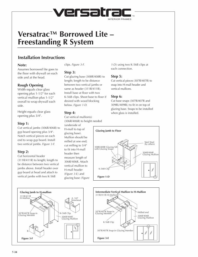
7-34
INTERIOR FRAMES
TM
Versatrac™ Borrowed Lite – Freestanding R System
Installation Instructions
Note:Assumes borrowed lite goes to the floor with drywall on each side and at the head.
Rough OpeningWidth equals clear glass opening plus 1-1/2" for each vertical mullion plus 1-1/2" overall to wrap drywall each side.
Height equals clear glass opening plus 3/4".
Step 1:Cut vertical jambs (306R/406R) to gyp board opening plus 3/4". Notch vertical pieces on each end to wrap gyp board. Install two vertical jambs. Figure 3-F.
Step 2:Cut horizontal header (311R/411R) to length; length to be distance between two vertical jambs above. Install header over gyp board at head and attach to vertical jambs with two K-56B
clips. Figure 3-F.
Step 3:Cut glazing base (308R/408R) to length; length to be distance between two vertical jambs or same as header (311R/411R). Install base at floor with two K-56B clips. Shoot base to floor if desired with wood blocking below. Figure 1-D.
Step 4:Cut vertical mullion(s) (306R/406R) to height needed (underside of H-mull to top of glazing base). Mullion should be milled at one end; cut milling to 3/4" to fit into H-mull header then measure length of 306R/406R. Attach vertical mullion to H-mull header (Figure 3-E) and glazing base (Figure
1-D) using two K-56B clips at each connection.
Step 5:Cut vertical pieces (307R/407R) to snap into H-mull header and vertical mullions.
Step 6:Cut base snaps (307R/407R and 309RL/409RL) to fit in on top of glazing base. Snaps to be installed when glass is installed.
311R/411R H-Mullion
307R/407R Snap-inGlazing Member
307R/407R Snap-in Glazing Member
306R/406RGlazing Mullion
Milled end
K-56B Clip
Intermediate Vertical Mullion to H-Mullion
Figure 3-E
311R/411RH-Mullion
307R/407R Snap-inGlazing Member
K-56B Clip
306R/406RGlazing Mullion
B.
A. 3/4"Knockout
Glazing Jamb to H-mullion
Figure 3-F
Steel Stud(by others)
306R/406RGlazing Mullion
308R/408R Glazing Sillwith Glazing Snaps
K-56B Clip
Glazing Jamb to Floor
Figure 1-D
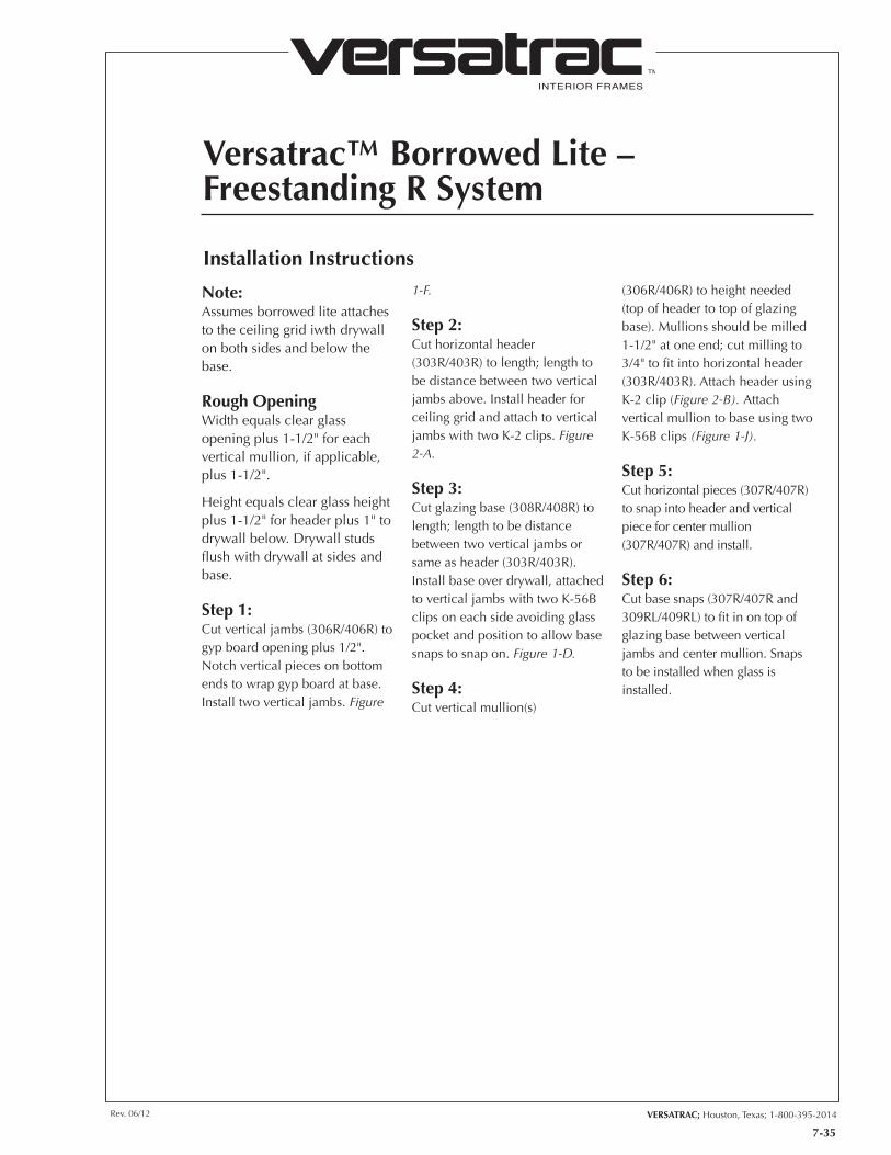
7-35
INTERIOR FRAMES
TM
VERSATRAC; Houston, Texas; 1-800-395-2014Rev. 06/12
Versatrac™ Borrowed Lite – Freestanding R System
Installation Instructions
Note:Assumes borrowed lite attaches to the ceiling grid iwth drywall on both sides and below the base.
Rough OpeningWidth equals clear glass opening plus 1-1/2" for each vertical mullion, if applicable, plus 1-1/2".
Height equals clear glass height plus 1-1/2" for header plus 1" to drywall below. Drywall studs flush with drywall at sides and base.
Step 1:Cut vertical jambs (306R/406R) to gyp board opening plus 1/2". Notch vertical pieces on bottom ends to wrap gyp board at base. Install two vertical jambs. Figure
1-F.
Step 2:Cut horizontal header (303R/403R) to length; length to be distance between two vertical jambs above. Install header for ceiling grid and attach to vertical jambs with two K-2 clips. Figure 2-A.
Step 3:Cut glazing base (308R/408R) to length; length to be distance between two vertical jambs or same as header (303R/403R). Install base over drywall, attached to vertical jambs with two K-56B clips on each side avoiding glass pocket and position to allow base snaps to snap on. Figure 1-D.
Step 4:Cut vertical mullion(s)
(306R/406R) to height needed (top of header to top of glazing base). Mullions should be milled 1-1/2" at one end; cut milling to 3/4" to fit into horizontal header (303R/403R). Attach header using K-2 clip (Figure 2-B). Attach vertical mullion to base using two K-56B clips (Figure 1-J).
Step 5:Cut horizontal pieces (307R/407R) to snap into header and vertical piece for center mullion (307R/407R) and install.
Step 6:Cut base snaps (307R/407R and 309RL/409RL) to fit in on top of glazing base between vertical jambs and center mullion. Snaps to be installed when glass is installed.
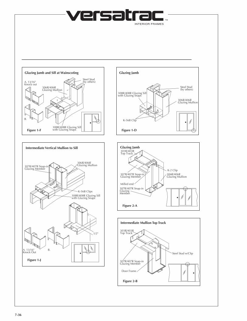
7-36
INTERIOR FRAMES
TM
308R/408R Glazing Sillwith Glazing Snaps
Steel Stud(by others)
306R/406RGlazing Mullion
A. 13/16"Knock out
B.
Glazing Jamb and Sill at Wainscoting
Figure 1-F
Steel Stud(by others)
306R/406RGlazing Mullion
308R/408R Glazing Sillwith Glazing Snaps
K-56B Clip
Glazing Jamb
Figure 1-D
307R/407R Snap-inGlazing Member
306R/406RGlazing Mullion
308R/408R Glazing Sillwith Glazing Snaps
K-56B Clips
A. 13/16"Knock Out
B.
1/2"
Intermediate Vertical Mullion to Sill
Figure 1-J
K-2 Clip307R/407R Snap-inGlazing Member
Milled end
303R/403RTop Track
306R/406RGlazing Mullion
307R/407R Snap-inGlazing Member
Glazing Jamb
Figure 2-A
Steel Stud w/Clip
307R/407R Snap-inGlazing Member
Door Frame
303R/403RTop Track
Intermediate Mullion Top Track
Figure 2-B
INTERIOR FRAMES
TM
VERSATRAC; Houston, Texas; 1-800-395-2014Rev. 06/12
8-1
Suggested SpecificationsDoor Opening Assemblies
Part 1 GeneralA. Work Included1. Furnish prefinished, extruded
aluminum door frames, including sidelight and borrowed light configurations for interior use.
B. Related Items Specified Elsewhere
1. Glass and Glazing Section ____________________2. Finish Hardware Section ____________________3. Painting Section ____________________
C. Quality Assurance1. Frames shall be manufactured by
a company regularly engaged in the manufacture of aluminum door frames and shall meet AAMA 603.7-1976 standards.
D. Submittals1. Provide complete shop drawings
of all door opening assemblies, indicating size, swing, finish, fire rating and construction.
2. Provide details of all accessories to be provided by manufacturer.
3. Provide elevation and section details of all door frames.
4. Provide manufacturer’s standard samples for frame finish selection.
E. Handling1. Handle all frames with care to
prevent damage.2. Keep frames in original
packaging until installation.3. Store all materials flat on a level
surface, protected from moisture and extremes of temperature.
F. Guarantee1. Guarantee interior aluminum
frames to be free of defect for period of one year from the date of the initial delivery, if properly protected, installed and maintained within the terms and
exclusions of the manufacturer’s warranty.
Part 2 - ProductsFrame Systems
A. Acceptable Manufacturer Versatrac; Houston, TX
1(800) 395-2014
B. Materials1. All frames shall be extruded
aluminum, of alloy 6063-T5, and of 0.062" minimum thickness.
2. Frames shall accommodate 3 3/4" or 4 7/8" walls (specify one).
3. Frames shall be quick-mount type, with extruded attached stud segments (for unfinished walls); or basic type, including separate, full-length aluminum studs (for prefinished walls), as specified
4. Frames shall be removable or relocatable.
5. Frames shall have all installation fasteners concealed when installed.
C. Finish1. All frames shall be prefinished in
Satin Metallic Bronze, Satin Black, or White thermosetting polymer acrylic, or Natural Clear Anodized finish, unless custom color or anodized finish is specified.
D. Construction1. Frames shall have hinge and
strike reinforcements of 0.125" extruded aluminum of alloy 6063-T5.
E. Hardware Preparation1. Frames shall be prepared for 4
7/8" ASA strike plate, or 2 3/4" ASA strike plate, dead bolt strike or jamb-mounted electrical strike if specified.
2. Frames up to nine feet in height
shall be prepared for three 4 1/2" x 4" ASA hinges. Preparations for fourth hinge optional.
3. Frames over nine feet in height shall be prepared for four 4 1/2" x 4" ASA hinges.
4. Frames shall be prepared for jamb-mounted closer reinforcement, if specified.
F. Door Stops1. Frames shall be furnished with
snap-on stops, with continuous mohair sound seal around entire frame perimeter. Vinyl sound seal optional, at additional cost.
G. Fire-Rated Frame Labels1. 20 minute Warnock-Hersey
labels shall be provided for all scheduled fire-rated frames.
2. Frames with 90 minute labels also available.
Part 3 - ExecutionA. Preparation1. Provide enough wall openings to
accommodate door opening assemblies as per manufacturer’s instructions.
B. Installation1. Door opening assemblies shall
be plumb, square and installed in the proper rough openings.
2. Manufacturer’s recommended installation instructions shall be followed.
3. Provide 1/8" clearance at hinge stile, 1/8" at lock stile, plus top and bottom clearance as specified. Bottom clearance on fire-rated doors shall not exceed NFPA 80 standard of 3/4".
4. Ensure that doors open and swing properly.
C. Cleaning1. Door opening assemblies shall
be cleaned with general, non abrasive cleaners suitable for painted surfaces. Wipe the surfaces with a soft, dry cloth.
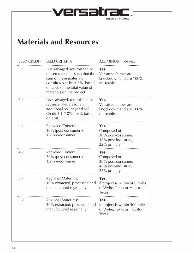
INTERIOR FRAMES
TM
Materials and Resources
LEED CREDIT LEED CRITERIA ALUMINUM FRAMES
3.1 Use salvaged, refurbished or reused materials such that the sum of these materials constitutes at least 5%, based on cost, of the total value of materials on the project.
Yes.Versatrac frames are knockdown and are 100% reuseable.
3.2 Use salvaged, refurbished or reused materials for an additional 5% beyond MR Credit 3.1 (10%) total, based on cost).
Yes.Versatrac frames are knockdown and are 100% reuseable.
4.1 Recycled Content:10% (post-consumer + 1/2 pre-consumer)
Yes.Composed of 30% post-consumer, 48% post-industrial, 22% primary
4.2 Recycled Content:20% (post-consumer + 1/2 pre-consumer)
Yes.Composed of 30% post-consumer, 48% post-industrial, 22% primary
5.1 Regional Materials:10% extracted, processed and manufactured regionally
Yes.If project is within 500 miles of Wylie, Texas or Houston, Texas
5.2 Regional Materials:20% extracted, processed and manufactured regionally
Yes.If project is within 500 miles of Wylie, Texas or Houston, Texas
8-2
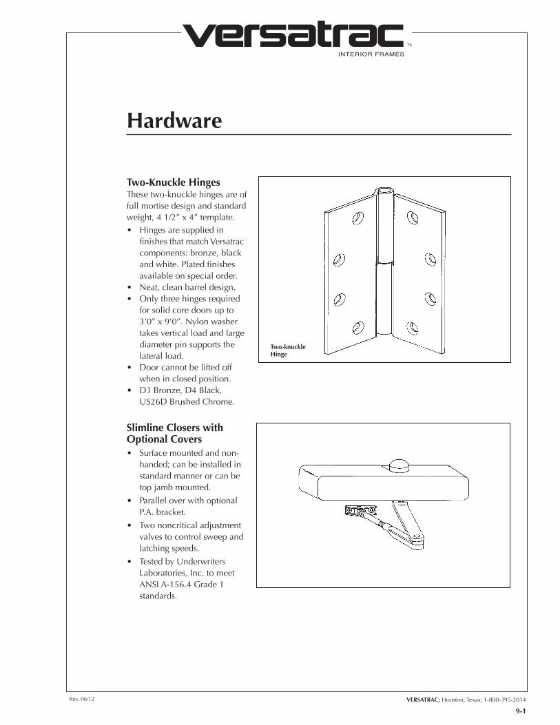
INTERIOR FRAMES
TM
VERSATRAC; Houston, Texas; 1-800-395-2014Rev. 06/12
9-1
Hardware
Two-knuckle Hinge
Two-Knuckle Hinges These two-knuckle hinges are of full mortise design and standard weight, 4 1/2” x 4” template.• Hingesaresuppliedin
finishes that match Versatrac components: bronze, black and white. Plated finishes available on special order.
• Neat,cleanbarreldesign.• Onlythreehingesrequired
for solid core doors up to 3’0”x9’0”.Nylonwashertakes vertical load and large diameter pin supports the lateral load.
• Doorcannotbeliftedoff when in closed position.
• D3Bronze,D4Black,US26DBrushedChrome.
Slimline Closers with Optional Covers• Surfacemountedandnon-
handed; can be installed in standard manner or can be top jamb mounted.
• ParalleloverwithoptionalP.A. bracket.
• Twononcriticaladjustmentvalves to control sweep and latching speeds.
• TestedbyUnderwritersLaboratories, Inc. to meet ANSIA-156.4Grade1standards.