
TX10 - User Guide - Thermo Fisher Scientific EXCEPT AS OTHERWISE AGREED TO IN WRITING BY Thermo...
81
Part of Thermo Fisher Scientific Polysonics TX10 Dedicated Transit Time Flowmeter User Guide P/N TX10-8000 Revision H
-
Upload
nguyenkien -
Category
Documents
-
view
214 -
download
1
Transcript of TX10 - User Guide - Thermo Fisher Scientific EXCEPT AS OTHERWISE AGREED TO IN WRITING BY Thermo...

Part of Thermo Fisher Scientific
Polysonics TX10Dedicated Transit Time FlowmeterUser GuideP/N TX10-8000
Revision H


Polysonics TX10Dedicated Transit Time FlowmeterUser GuideP/N TX10-8000
Revision H


© 2001 Thermo Fisher Scientific Inc. All rights reserved.
“Windows” is either a registered trademark or trademark of Microsoft Corporation in the United States and/or other countries. “SIL-GLYDE” is a trademark or registered trademark of American Grease Stick. “Dow Corning” is a registered trademark of Dow Corning Corporation. “GE” is a registered trademark of General Electric Company.
All other trademarks are the property of Thermo Fisher Scientific Inc. and its subsidiaries.
Disclaimer: Thermo Fisher Scientific (Thermo Fisher) makes every effort to ensure the accuracy and completeness of this guide. However, we cannot be responsible for errors, omissions, or any loss of data resulting from errors or omissions. Thermo Fisher reserves the right to make changes to the guide or improvement to the product at any time without notice. The material in this guide is proprietary and cannot be reproduced in any form without expressed written consent from Thermo Fisher.

This page intentionally left blank.

TABLE OF CONTENTS
1. General ................................................................................................................................................ 11.1 Specifications .................................................................................................................................... 1
1.1.1 Performance Specifications .......................................................................................................... 11.1.2 Physical Specifications ................................................................................................................ 11.1.3 Functional Specifications ............................................................................................................. 2
1.2 Warranty ........................................................................................................................................... 2
2. Meter Installation ................................................................................................................................. 42.1 Installing the Enclosure ..................................................................................................................... 4
2.1.1 Direct Mount Method ................................................................................................................... 42.1.2 Mounting Ears Method ................................................................................................................. 4
2.2 Wiring the Meter ................................................................................................................................ 52.3 Power Input Terminals ....................................................................................................................... 5
3. Transducers .......................................................................................................................................... 73.1 Wiring the Transducers ..................................................................................................................... 73.2 Spacing and Mounting the Transducers ............................................................................................. 7
3.2.1 V Method ..................................................................................................................................... 73.2.2 W Method .................................................................................................................................... 73.2.3 Z Method ..................................................................................................................................... 83.3 Insertion Transducers .....................................................................................................................12
3.3.1 General ....................................................................................................................................123.3.2 Parts ........................................................................................................................................123.3.3 Template Installation* ...............................................................................................................133.3.4 Transducer Installation .............................................................................................................143.3.5 Tapping Procedure ....................................................................................................................14
3.4 Site Recommendations ....................................................................................................................16
4. Configuration with WinGateE ............................................................................................................184.1 Interface ...........................................................................................................................................184.2 Installation ........................................................................................................................................18
5. Quick Setup Screen ...........................................................................................................................205.1 Transducer, Pipe Info, and Pipe ........................................................................................................205.2 Using OTHER as an Option ..............................................................................................................225.3 Totalizer ............................................................................................................................................23
5.3.1 Totalizer Units .............................................................................................................................235.3.2 Totalizer Multiplier .......................................................................................................................235.3.3 Totalizer Options .........................................................................................................................23
6. The Flow Screen ................................................................................................................................24

7. The Out/Calibration Screen ...............................................................................................................257.1 Out/Cal Tab ......................................................................................................................................25
7.1.1 4-20 mA OR Frequency Card ......................................................................................................257.1.1a Calibrating the 4-20 mA Card ..................................................................................................257.1.1.b Frequency Card .....................................................................................................................28
7.1.2 Setting the Current Loop Span ....................................................................................................317.1.3 Relay Options Group ..................................................................................................................327.1.4 Testing the Relay ........................................................................................................................337.1.5 Calibrating the Flowmeter ...........................................................................................................33
7.1.5.a Scale Factor ..........................................................................................................................337.1.5.b Zero Set ................................................................................................................................347.1.5.c Manual Zero Set Method .......................................................................................................34
7.2 Options Tab ......................................................................................................................................357.2.1 Comm/Display & Display ............................................................................................................357.2.2 Flow ............................................................................................................................................36
7.2.2.a Low Flow Cutoff .....................................................................................................................367.2.2.b Low Signal Cutoff ...................................................................................................................367.2.2.c Damping ................................................................................................................................36
7.2.3 Contrast ......................................................................................................................................377.2.4 Date/Time ...................................................................................................................................377.2.5 Modbus Address .........................................................................................................................37
8. The Data Log Screen .........................................................................................................................388.1 Viewing Your Current Log .................................................................................................................388.2 Zooming in on Data ..........................................................................................................................398.3 Saving Log Files ...............................................................................................................................408.4 Loading Log Files .............................................................................................................................408.5 Saving Configuration Files ................................................................................................................408.6 Loading Configuration Files ...............................................................................................................40
9. Manufacturing Data ............................................................................................................................41
10. The Master Erase Screen .................................................................................................................42
11. Troubleshooting, Maintenance, & Upgrades ..................................................................................4411.1 General ...........................................................................................................................................4411.2 Local Representative Support ..........................................................................................................4411.3 Flowmeter Maintenance ..................................................................................................................4411.4 Service & Returns ...........................................................................................................................4511.5 Upgrades ........................................................................................................................................4611.6 Ordering Information ........................................................................................................................46
12. Hazardous Area Installation .............................................................................................................4712.1 North American Certification ...........................................................................................................4712.2 European Certification ....................................................................................................................5012.3 North American Hazardous Area Installation Definitions ..................................................................5112.4 European Hazardous Area Installation Definitions ...........................................................................5112.5 CE Certification Requirements ........................................................................................................52
Appendix A: Measuring Flow on Small Diameter Pipes .....................................................................53A.1 General ............................................................................................................................................53A.2 Instructions ......................................................................................................................................53A.3 Additional .........................................................................................................................................54

Appendix B: Modbus Table .....................................................................................................................55B.1 General ............................................................................................................................................55B.2 Modbus Communication Setup ........................................................................................................55B.3 Register Map ...................................................................................................................................55B.4 Interpretation of Integer Variables .....................................................................................................57
Appendix C: Toxic & Hazardous Substances Tables* ...........................................................................60

This page intentionally left blank.

1
1. GENERAL
1.1 Specifications
1.1.1 Performance Specifications
Flow Range: ±0 to 40 ft./sec. (±0 to 12 m/sec.)
Accuracy: ±1.0% of velocity OR ±0.10 ft./sec. (±0.03 m/sec.) typical, whichever is greater
Sensitivity: 0.001 ft./sec. (0.3 mm/sec.) at any flow rate, including zero
Linearity: 0.1% of scale, digital output
Pipe Size: 1 in. to 200 in. (25 mm to 5 m)
1.1.2 Physical Specifications
Transmitter: NEMA 4X (IP65), flame retardant, fiberglass reinforced polyester (standard)NEMA 7 (optional)
Transducers: Encapsulated designStandard cable length: 30 ft. (9 m)Maximum cable length: 330 ft. (100 m)
Weight: Approximately 7 lb. (3.2 kg) without options
FIGURE 1

2
1.1.3 Functional Specifications
Outputs: 4-20 mA (into 1000 Ohms), 12 bit, 5 kV opto-isolated, loop or self-poweredRS232 serial interface
Power Supply: 85-265 Vac, 50/60 Hz (standard)7 W typical 10-32 Vdc (optional)
Display: 2 line X 20 character, backlit LCDIndicates flow rate, signal strength, total, and other selectable parameters
Optional Relay: Programmable 0.5 A, SPST (relay not available with 4-20 mA output)
Optional FrequencyBoard: Full scale output frequency selectable between 6 kHz and 47 Hz
Optional TotalizerOutput: Dry contact
Programming: Via WinGateE, compatible with Windows 98® and Windows 2000 operating systems
Temperature: Transducers: -40ºF to +212ºF (-40ºC to +100ºC)Transmitter: -40ºF to +140ºF (-40ºC to +60ºC)
Relative Humidity: Not exceeding 80%
1.2 Warranty
Thermo Scientific products are warranted to be free from defects in material and workmanship at the timeof shipment and for one year thereafter. Any claimed defects in Thermo Scientific products must bereported within the warranty period. Thermo Fisher shall have the right to inspect such products atBuyer’s plant or to require Buyer to return such products to Thermo Fisher plant.
In the event Thermo Fisher requests return of its products, Buyer shall ship with transportation charges paid by the Buyer to Thermo Fisher plant. Shipment of repaired or replacement goods from Thermo plant shall be F.O.B. Thermo Fisher plant. A shop charge may apply for alignment and calibration services. Thermo Fisher shall be liable only to replace or repair, at its option, free of charge, products which are found by Thermo Fisher to be defective in material or workmanship, and which are reported to Thermo Fisher within the warranty period as provided above. This right to replacement shall be Buyer’s exclusive remedy against Thermo Fisher.
Mains supply fluctuations: Not exceeding 10%
Overvoltage category II IEC 60364-4-443
Pollution degree 2
Altitude: to 2000 m

3
.....Warranty
EXCEPT AS OTHERWISE AGREED TO IN WRITING BY Thermo Fisher, THE WARRANTIES GIVEN ABOVEARE IN LIEU OF ALL OTHER WARRANTIES, EXPRESSED OR IMPLIED, AND Thermo Fisher HEREBYDISCLAIMS ALL OTHER WARRANTIES, INCLUDING THOSE OF MERCHANTABILITY AND FITNESSFOR PURPOSE.
Thermo Fisher shall not be liable for labor charges or other losses or damages of any kind or description, including but not limited to, incidental, special or consequential damages caused by defective products. Thiswarranty shall be void if recommendations provided by Thermo Fisher or its Sales Representatives are notfollowed concerning methods of operation, usage and storage or exposure to corrosive conditions.
Materials and/or products furnished to Thermo Fisher by other suppliers shall carry no warranty except suchsuppliers’ warranties as to materials and workmanship. Thermo Fisher disclaims all warranties, expressed orimplied, with respect to such products.

This page intentionally left blank.

4
2. METER INSTALLATION
2.1 Installing the Enclosure
The first step to installing and running the flowmeter is to install the enclosure. There are two methods ofmounting the enclosure: directly or by using the mounting ears.
2.1.1 Direct Mount Method
The enclosure can be directly mounted to a wall by inserting four 1/4-inch screws into the mounting wellsfrom the front of the enclosure.
2.1.2 Mounting Ears Method
The enclosure can also be mounted to a flat vertical surface using the mounting ears as follows (Figure2.1-A):
1. Screw the four mounting ears to the metal threaded inserts on the back of the enclosure using the5/16-inch screws provided in the mounting ears kit.
2. Attach the ears to the wall with standard mounting screws.
FIGURE 2.1-A

5
2.2 Wiring the Meter
All wiring should be routed through conduit or cable glands to seal the enclosure. The recommendedcable routing is illustrated in Figures 2.2-A and 2.2-B.
Figures 2.2-A (left) & 2.2-B (right)
2.3 Power Input Terminals
To prevent damage to the instrument, verify that the voltage to be connectedmatches the voltage rating of the flowmeter. The voltage rating is indicated beneaththe power input terminals.
The power input terminals seen in Figure 2.2-A can be connected to one of the following input voltages:
• 85 to 265 Vac
• 10 to 32 Vdc
The sheet metal access cover must be removed to gain access to the power input terminals and replacedafter the connections are completed. Power should be connected in accordance with local standardsor codes of practice.
To connect power for 120/240 Vac operation:
1. Connect the hot wire to the L1 terminal.
2. Connect the neutral wire to the N terminal.
3. Connect the ground wire to the GND terminal.
Disconnection from the supply MUST be possible via a customer-supplied switch or circuit breaker. This disconnection device should be clearly marked, in close proximity to the recorder, and easily accessible to the operator.

6
.....Power input terminals
To connect power for double phase 240 Vac operation:
1. Connect one hot wire to the L1 terminal.
2. Connect the other hot wire to the (L2) terminal.
3. Connect the ground wire to the GND terminal.
To connect power for 10 to 32 Vdc operation:
1. Connect the positive wire to the terminal labeled + (N).
2. Connect the negative wire to the terminal labeled - (L1).

This page intentionally left blank.

7
3. TRANSDUCERS
3.1 Wiring the Transducers
The transducer terminals and cables are arranged in pairs and are labeled DN STREAM and UPSTREAM. The downstream transducer cable has blue-banded ends; the upstream transducer has red-banded ends.
FIGURE 3.1
Locate the symbol seen in Figure 3.1 (left). This symbol is on bothpairs of terminals and indicate which terminals should connect to thecenter wire conductors and which should connect to the coaxialshields.
3.2 Spacing and Mounting the Transducers
Transducers (xducers) can be mounted with the V, W, or Z method.
3.2.1 V Method
The V method is considered the standard method.
Figure 3.2-A: V Mount
3.2.2 W Method
Flowmeter performance on small pipes with outer diameters of 2.5 inches (63.5 mm) or less can be improved by using the W method. See Figure 3.2-B (page 8).

8
.....W method
Figure 3.2-B: W Mount
3.2.3 Z Method
The Z method is used primarily in applications where the V method cannot work due to signal attenuationfrom excessive air or solids in the liquid, thick scale, poorly bonded linings, or very large pipes. Addition-ally, the Z method generally works better on larger diameter pipes where less pipe length is available formounting.
FIGURE 3.2-C: Z MOUNT

9
.....Z method
To mount transducers using the Z method:
1. Establish a reference at both the 3 o’clock and 9 o’clock positions on the pipe (Figure 3.2-D, below).
2. Place a transducer at the 3 o’clock position.
3. Trace the shape of the 3 o’clock transducer along its inside edge (opposite the cable connection).Draw a horizontal line at its center. Remove the transducer (Figure 3.2-E, below).
4. Obtain a continuous sheet of paper longer than the circumference of the pipe. Calculator paper tape orthermal printer paper works well for this.
5. Fold one end of the paper across the pipe’s width to produce a clean, straight edge.
6. Line the fold of the paper up with the horizontal centerline of the 3 o’clock transducer (Figure 3.2-F,below).
7. Wrap the paper firmly around the pipe, and mark the intersection point where the fold comes incontact with the rest of the paper (Figure 3.2-G, below).
FIGURES 3.2-D THROUGH 3.2-G (LEFT TO RIGHT, TOP TO BOTTOM)
8. Remove the paper from the pipe. Place the fold and intersection mark together again, and fold thepaper exactly in half (Figure 3.2-H, page 10).
9. Mark along the new fold (Figure 3.2-I, page 10).
10. Draw a horizontal line along the pipe from the centerline of the 3 o’clock transducer position. Refer toFigure 3.2-J (page 10), and use a level to ensure that the line is level with the top of the pipe. The lineshould be at least 3 inches (76 millimeters) longer than the transducer spacing calculated by thesoftware. For example, if the software calculates the spacing as 14 inches (356 millimeters), draw aline 17 inches (432 millimeters) long.

10
.....Z method
11. Measure the spacing from the inside edge of the 3 o’clock transducer, and mark this on the pipeFigure 3.2-K, below).
12. Wrap the paper firmly back on the pipe. Have the point where the ends of the paper come togetherline up with the horizontal line on the 3 o’clock side of the pipe. Ensure that the inside corner of thestraight edge of the paper is aligned with the mark made for the transducer spacing. Tape the paperdown, or have someone hold the paper in place (reference Figure 3.2-L, below).
FIGURES 3.2-H THROUGH 3.2-L (LEFT TO RIGHT, TOP TO BOTTOM)
13. Go to the other side of the pipe (9 o’clock position), and mark the pipe at the point where the markedfold and the inside edge of the paper length intersect (Figure 3.2-M, page 11).
14. Remove the paper from the pipe and trace the shape of the 9 o’clock transducer in the same manneryou did for the 3 o’clock transducer. Ensure that the inside edge of the transducer (opposite the cableconnection) is even with the point just marked on the 9 o’clock side of the pipe (Figure 3.2-N, page11).

11
.....Z method
FIGURES 3.2-M (LEFT) & 3.2-N (RIGHT)
15. Refer to Figure 3.2-O (below), and mount the transducers with pipe straps.
FIGURE 3.2-O
The figure below illustrates the final Z method installation.
FIGURE 3.2-P

12
3.3 Insertion Transducers
3.3.1 General
Insertion transducers should be considered where pipe conditions attenuate the ultrasonic signal of clamp-on transducers, preventing adequate flow readings. Such examples are:
• very large pipes with a wall thickness greater than 1”
• porous pipes such as concrete or clay
• mortar lined pipes where the lining may be cracked or broken
• pipes that may have a significant build up on the inner wall
3.3.2 Parts
FIGURE 3.3-A

13
3.3.3 Template Installation*
*May be supplied with original transducer purchase.
1. Cut out a template from a roll of mailing paper, butcher block paper, or a similar type of paper. Ensurethe corners are square (Figure 3.3-B, below)
2. Fold template exactly in half and crease in the middle (Figure 3.3-C, below).
Figures 3.3-B (left) & 3.3-C (right)
3. Wrap the template around the pipe so that the crease is on one side of the pipe and the two ends ofthe template meet on the other side of the pipe.
Try to line up the crease and ends with the horizontal center of the pipe. Tape the ends of thetemplate together with masking tape to hold it in place on the pipe. On a horizontal pipe, rotate thesleeve until the crease is in the 2 o’clock to 4 o’clock position.
Figures 3.3-D & 3.3-E: Completed Template

14
3.3.4 Transducer Installation
1. Choose one of the following options to install the 1.5” nipple:
• directly onto the pipe
• directly into a pipe saddle (reference Section 3.3.5 for tapping procedure)
• directly into a threadolet (reference Section 3.3.5 for tapping procedure)
The user must decide which of the above is the preferred method of installation.
2. Screw the 1.5” nipple onto the pipe usingone of the options stated in step 1. Use Teflon tape asneeded to create a leakproof seal.
3. Screw the 1.5” ball valve assembly onto the 1.5” nipple.
4. Loosen the collar, and pull the transducer assembly all the way out.
5. Screw the transducer assembly into the ball valve.
6. Take the measurement for distance A (seen in Figure 3.3-G).
7. Calculate X (seen in Figure 3.3-G).
8. Move the collar away from Point B the distance you calculated for X, and lock the collar.
9. Turn the valve handle to the “on” position and insert the transducer until the collar is seated on the sealhousing.
10. Tighten the retainer onto the seal housing.
3.3.5 Tapping Procedure
Follow these steps if you are installing the 1.5” nipple directly into a pipe saddle or directly into a threadolet.This procedure is to be performed by a qualified installer only.
1. Using Teflon tape, wrap the end of the male nipple and screw into the threadolet.
2. Screw ball valve onto nipple, and adjust valve to the “open” position.
3. Connect tapping machine into end of ball valve.
4. Use 1.12” minimum bit and drill through the pipe wall.
5. Back the bit out past the valve assembly, and move the valve handle to the “off” position.

15
.....Tapping procedure
FIGURES 3.3-F THROUGH 3.3-I (TOP TO BOTTOM)

16
3.4 Site Recommendations
Based on the setup parameters, WinGateE automatically calculates the required transducer spacing. Thenext step is selecting a proper transducer site. Figure 3.4-A and the following questions will assist you inchoosing a proper installation location:
• Is the section of pipe always full of liquid?
• Are there at least five pipe diameters upstream and three pipe diameters downstream from anydirectional changes, pipe joints, or narrowing/widening of the pipe?
Conditions at these locations in Figure 3.4-A can interfere with the transmission of the ultrasonic wave andyield inaccurate or unreliable flow readings.
FIGURE 3.4-A
• A - pipes may not be full
• B - down flow
• C - too close to the elbow
• D - air collects at the topof horizontal pipe
• E - sediment collects at the bottom of horizontalpipe
Once you have selected the appropriate installation site and mounting method, you can now mount thetransducers onto the pipe:
1. Clean the area of the pipe where the transducers are to be installed. Remove any rust, scale, or loosepaint. Well-bonded paint does not need to be removed.
On horizontal pipes, the transducers should be mounted in the 3 o’clock and 9o’clock positions. This prevents sediment from building up along the bottom ofthe pipe and gas bubbles or air pockets from forming along the top of the pipe.
2. Apply a wide bead of sonic coupling compound lengthwise down the center of the face of eachtransducer.
The coupling compound should squeeze out from around the edges of thetransducer when it is in place. There should be no air gaps between the transducerand the pipe.
For pipes 2.5” (63.5 mm) or smaller refer to Appendix A: Measuring Flow on SmallDiameter Pipes.
3. Attach the transducers to the pipe using the stainless steel pipe straps. Tighten both straps securely,ensuring that the transducers are aligned to the pipe.

17
.....Site recommendations
4. Connect the transducer cables to the instrument.
Reversing the position of the upstream and downstream transducers or thetransducer cable connections to the meter will result in negative flow readings.
5. Tighten the transducers sufficiently to prevent them from slipping and to allow for proper operation ofthe flowmeter.
FIGURE 3.4-B

This page intentionally left blank.

18
4. CONFIGURATION WITH WINGATEE
4.1 Interface
Connect the standard serial RS232 cable to the meter’s female DB9 RS232 interface.
4.2 Installation
Install the WinGateE software using the PolyCD:
1. Insert CD into drive.
2. Click the Start button in the bottom left corner of the desktop.
3. Click Run.
4. Click Browse and select the CD drive.
5. Select Setup.exe.
6. Click OK.
7. Follow the directions as they appear on the screen.
8. Once the PolyCD is installed, click the Start button in the bottom left corner of the desktop.
9. Click Programs, and click on PolyCD.
10. Click OK on the opening screen.
11. Select Run from CD in the following screen.
12. Select Communications Software.
13. Select WinGateE.
14. Follow the instructions as they appear on the screen.
15. After installation is complete, click Exit.
16. Click Exit again.

19
..... Installation
After software installation is complete, start WinGateE:
1. Click on the Start button in the bottom left corner of your desktop.
2. Select Programs, WinGateE.
Communication between the meter and the software will initiate, and the Quick Setup screen will bedisplayed.
Figure 4.2-A
If communications are not established, a Communications Failed screen will be displayed. Check for anyport conflicts on your PC, and resolve as necessary. Click OK. The Properties screen is displayed whichallows you to select a different port or change the baud rate. You do not need to change the ConnectionPreferences and Flow Control sections, as they are preset (see below).
Option Setting
Port Com1, Com2, etc.Maximum Speed 19200Data Bits 8Parity NoneStop Bits 1Flow Control None
After correcting communications port properties, click OK and the Quick Setup screen is displayed. Youare now ready to configure the software.

20
5. QUICK SETUP SCREEN
Figure 5 displays the Quick Setup screen. This screen requires entering all the information needed to getthe meter running.
FIGURE 5
5.1 Transducer, Pipe Info, and Pipe
Standard, Insertion PVC, and Insertion are the transducer types available. Selecting one of thesetransducers will alter the Quick Setup screen, allowing you to enter the information required for thatspecific transducer type. The software defaults to a standard type transducer.
If you are using a Standard transducer, ensure Standard is selected as the Transducer Type. Refer toFigure 5.1-A (page 21), and supply the following information by clicking on each pull down menu:
• pipe material*• liner material*• fluid type*• flow units• mounting• units
*See Section 5.2 if you choose OTHER.

21
.....Transducer, pipe info, and pipe
FIGURE 5.1-A
In the Pipe section, provide:
• outer diameter of pipe (OD)• wall thickness• liner thickness (if applicable)
FIGURE 5.1-B
The software will calculate the inner diameter of the pipe (ID) after you enter the OD and wall thickness.
If you are using a steel, stainless steel, or PVC pipe, select the nominal pipe sizeand schedule. WinGateE will automatically calculate the pipe OD, pipe ID, andwall thickness.
For Insertion PVC (option) or Insertion transducers, select the appropriate type. Refer to Figure 5.1-C(page 22), and supply the following information by clicking on each pull down menu:
• fluid type*• flow units• units
*See Section 5.2 if you choose OTHER.

22
.....Transducer, pipe info, and pipe
FIGURE 5.1-C
In the Pipe section, provide:
• inner diameter of pipe (ID)
FIGURE 5.1-D
5.2 Using OTHER as an Option
If the pipe material, liner material, or fluid type you are using is not listed in the drop down menu, chooseOTHER.
Figure 5.2-A (page 23) shows the additional menu which is displayed when you select OTHER as yourpipe material, liner material, and fluid type.
The following information is required when selecting OTHER as your:
• pipe material - pipe sound speed, pipe roughness• liner material - liner sound speed, liner roughness, liner wall• fluid type - fluid sound speed, fluid viscosity
Once you provide the information, click OK.

23
.....Using OTHER as an option
FIGURE 5.2
5.3 Totalizer
5.3.1 Totalizer Units
FIGURE 5.3-A
You can set the totalizer units by clicking on the drop down menu. Thetotalizer unit selected can be different from the flow rate unit.
5.3.2 Totalizer Multiplier
Select the totalizer multiplier by clicking on the drop down menu.
5.3.3 Totalizer Options
Choose one of the three totalizers available:
• Positive - tracks the flow moving from the upstream transducer to the downstream transducer
• Negative - tracks the flow moving from the downstream transducer to the upstream transducer
• Net - provides the difference between the positive and negative flow values
To reset the totalizer(s): choose which one you would like reset by clicking in the check box next to thattotalizer option. Click the Reset Totalizer button. If you change any Totalizer options and click Send, clickOK to reset the totalizer. Click Cancel if you want to keep the existing setup.
Click Send after entering all setup requirements to send the information to the flowmeter.

24
6. THE FLOW SCREEN
The information being read by the flowmeter is displayed to the left of the graph.
Figure 6

This page intentionally left blank.

25
7. THE OUT/CALIBRATION SCREEN
The Out/Calibration screen consists of two tabs: the Out/Cal tab and the Options tab.
7.1 Out/Cal Tab
FIGURE 7.1-A
7.1.1 4-20 mA OR Frequency Card
7.1.1.a Calibrating the 4-20 mA Card
If you are using the 4-2 0mA card, begin calibration by clicking in the 4-20mA or Freq check box. Click inthe Test/Calibrate check box. Click on the Calibrate button.
FIGURE 7.1-B
Follow the five steps as they appear on the screen (references figures on the following pages). See Figure7.1-H for location of current loop module.

26
.....Calibrating the 4-20 mA card
FIGURES 7.1-C THROUGH 7.1-E (TOP TO BOTTOM)

27
.....Calibrating the 4-20 mA card
FIGURES 7.1-F THROUGH 7.1-H (TOP TO BOTTOM)

28
7.1.1.b Frequency Card
The frequency card is designed to provide a high impedance 24 Vdc square wave output to a frequencycounter (Figure 7.1-I) as well as a low impedance signal for driving an optocoupler (Figure 7.1-J).
FIGURES 7.1-I (LEFT) & 7.1-J (RIGHT)
If you are using a frequency card, begin calibration by clicking in the Frequency Card check box.
FIGURE 7.1-K
Select the desired maximum frequency range from the table. Click OK, and install the jumper as required.
FIGURE 7.1-L
Select the frequency range from the pull down menu. Click in the Test/Calibrate check box. Then click theCalibrate button. Follow the five steps as they appear on the screen. Refer to the figures on the followingpages.

29
.....Frequency card
FIGURES 7.1-M THROUGH 7.1-O (TOP TO BOTTOM)

30
.....Frequency card
FIGURES 7.1-P THROUGH 7.1-R (TOP TO BOTTOM)

31
.....Frequency card
FIGURE 7.1-S
7.1.2 Setting the Current Loop Span
You can set the span after calibrating the current loop:
1. Click in the 4-20mA check box.
2. Enter the flow rate that equals the 4 mA (minimum) reading in the Flow Rate at 4mA text box.
3. Enter the flow rate that equals the 20 mA (maximum) reading in the Flow Rate at 20mA text box.
FIGURE 7.1-T

32
7.1.3 Relay Options Group
1. Select the relay you want to program.
2. Select the mode:
• Off - turns off relay functions
• Program - enables programming of the relay ON and OFF conditions
• Pulse Net - sends a pulse to a remote device whenever the net totalizer advances by one unit
• Pulse Pos - sends a pulse to a remote device whenever the positive totalizer advances by one unit
• Pulse Neg - sends a pulse to a remote device whenever the negative totalizer advances by oneunit
FIGURE 7.1-U
Selecting the Program option opens another screen which allows you to enter therelay On and Off conditions (Figure 7.1-U). See the following steps.
1. Select the desired On condition.
2. Select the desired modifier - greater than (>) or less than (<).
3. Click in the text box, and enter the On condition value.
4. Repeat steps to set the relay Off conditions.
FIGURE 7.1-V

33
7.1.4 Testing the Relay
1. Click in the Test Relay check box.
2. Click on the On or Off buttons. During the test, the relay should audibly click as it opens or closes.The relay’s LED should light up when the relay is on.
3. End the test by clicking in the Test Relay check box to remove the check mark.
Figure 7.1-W
7.1.5 Calibrating the Flowmeter
7.1.5.a Scale Factor
After the instrument’s zero point has been set and verified, a scale factor can be set to adjust themeasured flow. The flow measured by the instrument is multiplied by this scale factor. For example, if thedisplayed flow is twice the actual flow, a scale factor of 0.5 divides the displayed flow by two.
The scale factor is preset at the factory and is imprinted on the transducers. If an additional scale factor isrequired by the user, the additional factorshould be multiplied by the factory scale factor. Enter the result inthe Scale Factor text box.
Always determine the scale factor at the highest possible flow rate achievable inorder to maximize the accuracy of the scale factor.
1. Enter the number to be used as the scale factor in the Scale Factor text box.
2. Click Send.
Once the flowmeter has received the information, the Flow screen will be displayed.

34
7.1.5.b Zero Set
Once the meter is installed, a small adjustment to the zero point, called zero set calibration, may berequired. Zero set calibration allows the flowmeter to read very close to zero under zero flow conditions.
Prior to performing a zero set calibration, follow these steps:
1. Ensure the transducers are connected to the pipe and the instrument is reading flow.
2. Disable the low flow cutoff to allow the calibration to be verified.
Begin the zero set calibration:
1. Click on the Zero Flow button.
FIGURE 7.1-X
2. Click Yes to perform the zero setcalibration. Then click Send. The Flow screen will be displayed.Click No if you do not want to perform the zero set calibration.
7.1.5.c Manual Zero Set Method
The zero point can be manually entered with the manual zero set method.This method applies a constantoffset entered by the user.
1. Follow the preliminary steps outlined in Section 7.1.5.b
2. Minimize the flow occurring in the pipe.
3. Set the damping so that the flowmeter reads a steady flow.
4. Enter 0 in the Zero Flow text box.
5. Click Send.
6. Take ten separate flow readings, and determine their average. This average is designated as thevariable P for positive.
7. Disconnect the transducer wiring connections at the flowmeter, and reverse the upstream wires anddownstream wires. The flowmeter will begin to display a negative flow reading.
8. Allow the flowmeter to settle for 10 minutes.

35
.....Manual zero set method
9. Take another ten flow readings, and determine their average. This new value is designated as thevariable N for negative.
10. Determine the manual zero point (Zp) by calculating the following formula:
11. Enter this number in the Zero Flow text box.
12. Click Send.
13. Reconnect the transducer wires according to their original orientation.Once the flowmeter hasreceived the information, the Flow screen will be displayed.
7.2 Options Tab
The Options group contains several miscellaneous functions.
FIGURE 7.2-A
7.2.1 Comm/Display & Display
In the Comm/Display section you can change the following information:
• baud rate of which the meter communicates with the software
• the unit name (Tag), using any combination of alphanumeric characters
• the unit identification number, using any whole number between one and 32,000
The Display section can be configured to indicate any combination of flow rate, totalizer, or signal strengthvalues. For multiple selections, enter a cycle time which allows the display to alternate betweenselections.

36
.....Comm/Displays & display
If you do not make any selections, the meter will default to factory settings and display flow and date/timevalues.
FIGURE 7.2-B
7.2.2 Flow
7.2.2.a Low Flow Cutoff
FIGURE 7.2-C
When a zero flow condition occurs, internal sloshing and otherfluid movement can prevent the flowmeter from reading total zero.This can result in totalizer errors. These errors can be minimizedby entering a low flow cutoff. Setting a low flow cutoff drives theflowmeter to zero for flow rates at or below that value.
7.2.2.b Low Signal Cutoff
Empty pipes, solids, bubbles, or voids in the flow stream may cause temporary drops in signal strength.The effect of these dropouts can be minimized by setting a low signal cutoff.
7.2.2.c Damping
The damping coefficient suppresses short term fluctuations in the indicated flow rate. Increasing thecoefficient increases the response time to changes. Damping should be kept at a minimum unless the flowrate fluctuates wildly. If so, damping should be increased just enough to reduce the fluctuation to anacceptable degree.
The value for the low flow cutoff should be set as high as is practical to maximizethe stability of the zero flow setting.
The value for the low signal cutoff should typically be set at approximately one-half of the value of the signal strength present under low flow conditions.
Click the Send button in the bottom right corner of the screen after entering all desired information.

37
7.2.3 Contrast
FIGURE 7.2-D
Click and drag the pointer to adjust the contrast on your flowmeter.
7.2.4 Date/Time
Set the date and time:
1. Click Set Clock.
2. Enter the correct date in month/date/year (MM/DD/YYYY) format.
3. Enter the time in hour/minute/second (HH/MM/SS) format.
4. Click Send.
7.2.5 Modbus Address
FIGURE 7.2-E
Enter a Modbus address that will be used in your system. The address numbershould be between 1 and 254. Refer to Appendix B for additional details on Modbusfunctionality.

This page intentionally left blank.

38
8. THE DATA LOG SCREEN
8.1 Viewing Your Current Log
After completing the software and hardware configurations, you can set up the data log by clicking on theLog tab.
FIGURE 8.1-A
Customize your log to capture data in various time intervals:
1. Click the drop down menu for the Interval (Sec) button.2. Select the desired time interval.3. Click on the Start Log button.
FIGURE 8.1-B

39
.....Viewing your current log
4. Click the Get Log Header button to view and update pertinent log information (Figure 8.1-C).5. Click the Get Log button to update the log itself (Figure 8.1-D).6. Click the Stop Log button to end the data collection in order to save the log.
The information displayed below the Get Log and Stop Log buttons are the starting/ending dates and timesfor that log, as well as the recorded high and low flows.
FIGURES 8.1-C (LEFT) & 8.1-D (RIGHT)
8.2 Zooming in on Data
FIGURES 8.2-A (TOP) & 8.2-B (BOTTOM)
You can zoom in on selected areas of data:
1. Move your mouse to a point on the screen.
2. Depress the left mouse button, and drag the mouse toenclose the range of data you want to zoom in on.
3. Release the mouse button.
4. Repeat steps 1-3 until you achieve your desired view.
5. Return to the original view by clicking in the Zoom check box.

40
8.3 Saving Log Files
1. Click on the File button in the main WinGateE screen.
2. Select Save Log.
3. Type in the log file name, and click Save.
8.4 Loading Log Files
1. Click on the File button in the main WinGateE screen.
2. Select Load Log.
3. Select the log file you want to load, and click Open.
Use standard Windows procedures for saving log files on your computer or floppy disk and for loading logfiles from your computer or floppy disk.
You can import log files into any data processing or spreadsheet software.
8.5 Saving Configuration Files
You can save multiple pipe configurations:
1. Click on the File button in the main WinGateE screen.
2. Select Save Configuration.
3. Type in the configuration file name, and click Save.
8.6 Loading Configuration Files
1. Click on the File button in the main WinGateE screen.
2. Select Load Configuration.
3. Select the configuration file you want to load, and click Open.

This page intentionally left blank.

41
9. MANUFACTURING DATA
The MFG screen contains flowmeter software and hardware information used by the factory.
FIGURE 9

This page intentionally left blank.

42
10. THE MASTER ERASE SCREEN
The Master Erase tab can only be viewed when the flowmeter is turned off. Perform a master erase onlywhen you want all configuration information deleted and reset to factory defaults.
1. Exit WinGateE if it is currently running.
2. Turn the flowmeter off.
3. Open WinGateE.
4. Click OK on the Communications Failed Screen.
5. Select the correct Port and Baud Rate. Click Cancel.
6. The opening screen now has a Master Erase tab. Click on it, and follow the steps.
FIGURE 10-A
7. Click Connect. Turn on the flowmeter, and wait for it to connect to the software (Figures 10-B and 10-C, page 43).
8. Click the Master Erase button and then the Start Program button. WinGateE will display the openingscreen with all factory defaults. You are now ready to re-configure the meter (Figure 10-D, page 43).

43
.....The Master Erase screen
FIGURES 10-B THROUGH 10-D (TOP TO BOTTOM)

44
11. TROUBLESHOOTING, MAINTENANCE, & UPGRADES
11.1 General
If the unit does not perform satisfactorily, complete the following steps until the problem is resolved:
1. Verify that the flowmeter was properly installed and that the installation site was suitable.
2. Verify that the flowmeter was properly configured.
3. Perform a Master Erase.
4. Contact the installation contractor or representative through whom the flowmeter was purchased.
5. Contact Thermo Fisher to attempt to resolve the problem over the phone.
6. If Thermo Fisher determines that the problem cannot be resolved over the phone, return the entire unit.
11.2 Local Representative Support
The local representative is the first contact for support and is well equipped to answer questions andprovide application assistance. Your representative has access to product information and currentsoftware revisions.
11.3 Flowmeter Maintenance
The flowmeter is easy to maintain. The transducers and flowmeter are factory service only componentsand maintenance free. The following table describes system components, appropriate maintenanceactions, and the recommended maintenance schedule.
Component Recommended Maintenance How Often
Transducers None, this is a service item. -----
*Coupling compound Add more compound Annually OR whenever:• compound diminishes• repositioning transducers• relocating meter
Flowmeter None, this is a service item ----
Cable connectors Make sure connections are secure; As part of your facility’sremove any resident buildup within maintenance schedulethe connection.
*Coupling compound should be protected from washout and replaced as required. Annual replacement isrecommended for most applications to maintain optimal performance.

45
.....Flowmeter maintenance
To replace the coupling compound:
1. Remove the transducers from the pipe.
2. Clean the old compound from the transducers and the pipe.
3. Apply a wide bead of compound lengthwise down the center of the face of each transducer.
4. Remount the transducers, verifying that the compound is squeezing out from underneath all sides ofthe transducers and forming a bead along the edges.
The following sonic coupling compounds are recommended:
• SIL-GLYDE®, which is made from a silicon base and is suited for most transducer installations. It israted for pipe skin temperatures from -20ºF to +400ºF (-28.9ºC to 204ºC).
• Dow Corning® 111 or similar high temperature couplant, which should be used for applications withpipe skin temperatures up to 470ºF (243ºC).
• GE® RTV-108 or similar silicon RTV, which should be used for underground or submergedtransducer sites or sites where a more permanent bond is required. The RTV should be completelycured prior to covering up the transducer site or taking readings.
11.4 Service & Returns
If it becomes necessary for you to contact Thermo Fisher with software or hardware problems, please have the following information available:
• signal strength • transducer type and mounting configuration• pipe orientation • pipe OD• pipe ID • pipe material• fluid type • liner material• liner thickness • model and serial numbers
To ship an instrument to Thermo Fisher:
1. Contact Thermo Fisher for an RMA number (issued by a service representative). The receiving dock will not accept shipments without the RMA number.
2. Ensure the instrument is well packed (in its original shipping box if available).
3. Include a letter fully explaining the symptoms of the failure as well as details describing the applicationwhere the unit was being operated (type of fluid, pipe size, pipe material, fluid velocity, etc.).
4. Write the RMA number on the outside of the shipping box.
5. Send the unit freight-paid to Thermo Fisher.

46
.....Service & returns
To contact Thermo Fisher:
• Web: www.thermo.com • Address: Thermo Fisher Scientific• Fax: 713-272-2272 1410 Gillingham Lane• Phone: 713-272-0404 Sugar Land, TX 77478 USA
11.5 Upgrades
Thermo Fisher provides the most current software for your meter at time of shipment. Upgrade software asnewer versions become available using the RS232 port and a remote terminal.
Find out about upgrades by contacting Thermo Fisher via mail, fax, phone, or web.
11.6 Ordering Information
Model Product Description
Polysonics TX10 Dedicated transit time flowmeterFlow range ±0 to 40 ft./sec. (±0 to 12 m/sec.)10,000 point data loggerTwo-line LCD, backlit displayRS232 digital communication interfaceWinGateE flowmeter configuration and analysis programStandard transducers
Code Outputs
1 4-20 mA DC2 4-20 mA DC, one 0.5 A, 10-W SPST programmable relay
Code Power Supply
1 85-265 Vac2 10-32 Vdc
Code Transmitter Enclosure
1 NEMA 4X (IP65)2 NEMA 7
Code Transducer Cable Length
30A 30 ft. (9 m) cable - standardXXXX Additional cable - maximum 330 ft. (100 m), sold in 10 ft. (3 m) incrementsXXXX Additional insertion transducer cable, maximum 100 ft. (30 m), sold in
10 ft. (3 m) increments

This page intentionally left blank.

47
12. HAZARDOUS AREA INSTALLATION
This chapter covers requirements for installing the INSTRUMENT in hazardous area applications. Hazardousarea certification for North America is provided by the Canadian Standards Association (CSA). Certificationfor Europe is provided by Laboratoire Central des Industries Electrique (LCIE).
The area classification determines the type of enclosure to be used and whether barriers are required. Ifbarriers are required, they are installed by the factory to meet the appropriate agency certification.
The standard enclosure for the instrument is a NEMA 4X (IP65).
If transducers are approved for use in hazardous areas, a logo of the certifying agency is affixed to thetransducers.
12.1 North American Certification
The transducers are certified by CSA as follows:
• Intrinsically safe (IS) transducer for Classes I and II, Div. I, Groups A, B, C, D, E, F, and G (IS barriers
required);
• Non-incendive for the following areas (IS barriers not required):
- Class I, Div. 2, Groups A, B, C, and D.
The table below lists CSA’s hazardous area installation requirements for North America.
Table 4: North American Hazardous Area Installation Requirements
Item Division 1 Division 2 Unclassified
Instrument N/A NEMA 4X enclosure NEMA 4X enclosure
Transducers IS, barriers required Non-incendive, barriers not required Barriers not required
Installation drawing Figure 12.1-A Figure 12.1-B N/A
The flowmeter must be installed and wired in accordance with the specified installation drawing.
To minimize the possibility of explosion, do not disconnect equipment unless thearea is known to be non-hazardous. In addition, do not replace the fuse or outputmodule unless power has been switched off or the area is known to be non-hazardous.
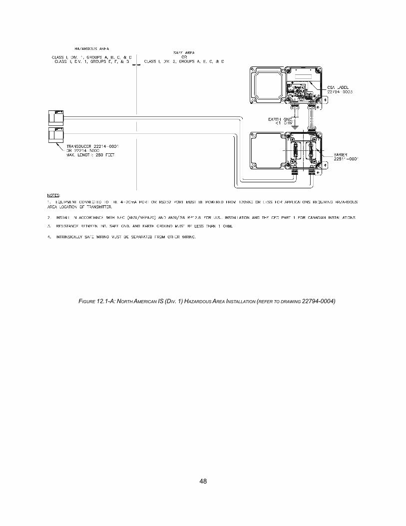
48
FIGURE 12.1-A: NORTH AMERICAN IS (DIV. 1) HAZARDOUS AREA INSTALLATION (REFER TO DRAWING 22794-0004)

49
FIGURE 12.1-B: NORTH AMERICAN NONINCENDIVE (DIV. 2) HAZARDOUS AREA INSTALLATION (REFER TO DRAWING 22794-0002)

50
FIGURE 12.2: EUROPEAN HAZARDOUS AREA INSTALLATION (REFER TO DRAWING 22493-0005)
12.2 European Certification
The transducers are certified IS by LCIE for EEx ia IIB T6 when IS barriers are installed. The table belowlists the European hazardous area installation requirements.
Table 5: European Hazardous Area Installation Requirements
Item Zone 0 Zone 1 Zone 2 Unclassified
Instrument N/A EExd1 enclosure EExd1 enclosure IP65 enclosure
Transducers EEx ia, EEX ia, EEX ia, Barriers not required
barriers required barriers required barriers required
Installation drawing2 Figure 12.2 Figure 12.2 Figure 12.2 N/A
1 Instrument should be installed in accordance with required codes, including use of explosion-proof sealsfor the wiring connections to the enclosure.
2 The flowmeter must be installed and wired in accordance with the specified installation drawing.

51
12.3 North American Hazardous Area Installation Definitions
This section provides hazardous area installation definitions for North America to assist in determining theoperating environment for the INSTRUMENT. Refer to the National Electrical Code (NEC) Article 500 for moreinformation on hazardous area definitions for North America.
Class I: Highly flammable gases or vapors
Class II: Combustible dust
Class III: Combustible fibers or flyings
Division 1: Intermittent or continuous hazard
Division 2: Hazard under abnormal conditions
Group A: Atmospheres containing acetylene
Group B: Atmospheres containing hydrogen or gases of equivalent hazard
Group C: Atmospheres containing ethyl-ether vapors, ethylene or cyclopropane
Group D: Atmospheres containing gasoline, hexane, benzene, butane, propane, alcohols, acetone,benzol, lacquer solvent vapors, or natural gas
Group E: Atmospheres containing metal dust
Group F: Atmospheres containing coal dust
Group G: Atmospheres containing grain dust
NEMA 4X: Watertight enclosures; must pass hose test using 1-inch nozzle delivering 65 GPM at a 10-ftdistance for 5 minutes; additional corrosion-resistant characteristics, having no exposed metal surfaces
NEMA 7: Explosion-proof enclosures for indoor hazardous locations (Class I, Groups A, B, C, and D)
12.4 European Hazardous Area Installation Definitions
This section provides hazardous area installation definitions for Europe to assist in determining the operatingenvironment for the INSTRUMENT. Refer to International Electrotechnical Commission (EIC) 79 for moreinformation on hazardous area definitions for Europe.
EEx ia IIB T6: IS classification; surface industry equipment used in flammable atmospheres equivalent toethylene or less; maximum surface temperature of 185º F (85º C)
IP65: Dust-tight enclosure; protection against low pressure jets of water from all directions (limited ingresspermitted)

52
12.5 CE Certification Requirements
The table below provides supplemental information for European units requiring CE certification.
Table 6: CE Certification Requirements
Insulation rating Double
Environmental operating • Pollution degree: 1
conditions (per EN-61010-1) • Installation category (over-voltage): II
Peripheral connections Equipment should only be connected to peripherals conforming to
installation category II
External isolator Switch or circuit breaker must be located near the equipment if the
equipment is to be permanently connected
Fuses (per EN-61010-1, • User-replaceable fuse for AC-powered versions: 500 mA, 250 V, quick
Sections 5.1.4 and 5.4.5) acting, 5 x 20 mm
• User-replaceable fuse for DC-powered versions: 1 A, 250 V, quick
acting, 5 x 20 mm
• Non user-replaceable fuse for all versions: 5 A, 250 V, quick acting
Output isolation 5 kVac surge isolation when powered from an external source; not to be
connected to continuous voltages in excess of 50 Vac with respect to
ground (earth)
53
APPENDIX A: MEASURING FLOW ON SMALL DIAMETER PIPES
A.1 General
To enhance stability when measuring flow on 1.5 to 3.5 in. stainless steel or copper pipes OR 1.5 to 2.5 in.PVC, carbon steel, or other pipes at an operating temperature range of -20ºF to +240°F, follow the stepsoutlined in section A.2.
The W mount method is recommended for pipe sizes equal or less than 2.5 in. unless signal strength isless than 50%. However, the V method is used when the W method cannot work due to signalattenuation from excessive air or solids in the liquid, thick scale, or poorly bonded linings.
A.2 Instructions
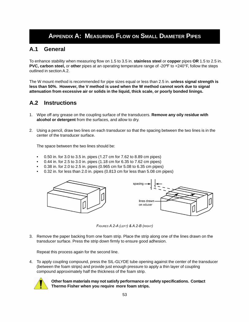
1. Wipe off any grease on the coupling surface of the transducers. Remove any oily residue withalcohol or detergent from the surfaces, and allow to dry.
2. Using a pencil, draw two lines on each transducer so that the spacing between the two lines is in thecenter of the transducer surface.
The space between the two lines should be:
• 0.50 in. for 3.0 to 3.5 in. pipes (1.27 cm for 7.62 to 8.89 cm pipes)• 0.44 in. for 2.5 to 3.0 in. pipes (1.18 cm for 6.35 to 7.62 cm pipes)• 0.38 in. for 2.0 to 2.5 in. pipes (0.965 cm for 5.08 to 6.35 cm pipes)• 0.32 in. for less than 2.0 in. pipes (0.813 cm for less than 5.08 cm pipes)
FIGURES A.2-A (LEFT) & A.2-B (RIGHT)
3. Remove the paper backing from one foam strip. Place the strip along one of the lines drawn on thetransducer surface. Press the strip down firmly to ensure good adhesion.
Repeat this process again for the second line.
4. To apply coupling compound, press the SIL-GLYDE tube opening against the center of the transducer(between the foam strips) and provide just enough pressure to apply a thin layer of couplingcompound approximately half the thickness of the foam strip.
Other foam materials may not satisfy performance or safety specifications. ContactThermo Fisher when you require more foam strips.

54
..... Instructions
FIGURES A.2-C (LEFT & A.2-D (RIGHT)
OPTIONAL STEP
To further reduce noise level, apply a thin layer of grease to the backside of the pipe (opposite thetransducers).
A.3 Additional
FIGURE A.3
If there are no foam strips available:
1. Apply coupling compound onto the transducer surfaces as usual.
2. Clamp the transducers onto the pipe.
3. Using a pen sized, slotted screw driver, remove the extra greasebetween the transducers and the pipe.
Do not use this method on high temperature(240°F) applications.
This method may not provide reliable results onlong term outdoor applications.

55
APPENDIX B: MODBUS TABLE
B.1 General
The Modbus table defines a limited subset of configuration and run-time variables for the flowmeter.Regardless of your application, you should first configure the flowmeter using UltraScan. You can set aModbus address in UltraScan by accessing the Option tab on the Out/Calibration page. The addressshould be between 1 and 254 (0xFE). Address 255 (0xFF) is reserved.
When the flowmeter is started, you can poll basic real-time information such as flow rate, signal level, andsound speed. The only control to the flowmeter through Modbus is to reset the totalization registers.
B.2 Modbus Communication Setup
• Modbus RTU protocol
• 8 data bits
• 1 stop bit
• No parity
• 19200 baud rate
B.3 Register Map
• Registers in the 7000-7021 range will be a 32-bit floating value. All variables defined in the table canbe accessed using this set of registers.
• Registers in the 3000-3009 range will return a 16-bit integer value.
• Registers in the 3500-3521 range must be read two registers at a time. They will return an integervalue between 2 and 16 bits that, when combined, will represent a 32-bit float point value.
TABLE B.3-A: MANUFACTURING INFORMATION
Register Variable Description Read/Write Comments
3000 7000
m_pCom->m_addr Unit ID (Modbus) Read Data Type = Integer
3001 7001
pSC-> m_nOptionsUnitType
Unit Type Read/Write Data Type = Integer

56
.....Register map
TABLE B.3-B: METER OUTPUT
TABLE B.3-C: METER CONFIGURATION
Register Variable Description Read/Write Comments
3500 & 3501 7002
pCD-> m_dFlowOut Gross Flow Rate Read Data Type = Double
3502 & 3503 7003
pCD-> m_nvram. m_dTotal
Accumulated Gross Total
Read/Write Any Write Resets Accum. Date Type = Double
3504 & 3505 7004
pCD-> m_nvram. m_dTotalPos
Forward Gross Total
Read/Write Any Write Resets Accum. Data Type = Double
3506 & 3507 7005
pCD-> m_nvram. m_dTotalNeg
Reverse Gross Total
Read/Write Any Write Resets Accum. Data Type = Double
3508 & 3509 7006
pCD-> m_dSigStrength
Signal Strength Read Data Type = Double
Register Variable Description Read/Write Comments
3002 7007
pCC-> m_nFlowUnits
Volume Units Read Data Type = Integer
3003 7008
pCC-> m_nFlowUnitsPer
Flow Time Base Read Data Type = Integer
3004 7009
pCC-> m_nTotalizerUnits
Totalizer Units Read Data Type = Integer
3005 7010
pCC-> m_nTotalizerMult
Totalizer Scaling Read Data Type = Integer
3006 7011
pCC-> m_nPipeMaterial
Pipe Material Read Data Type = Integer
3510 & 3511 7012
pCC-> m_dPipeOD Pipe OD Read Data Type = Double
3512 & 3513 7013
pCC-> m_dPipeWall Pipe Wall Thickness
Read Data Type = Double
3007 7014
pCC-> m_nLinerMaterial
Liner Material Read Data Type = Integer

57
.....Register map
TABLE B.3-C: METER CONFIGURATION CONTINUED
B.4 Interpretation of Integer Variables
TABLE B.4
Register Variable Description Read/Write Comments
3007 7014
pCC-> m_nLinerMaterial
Liner Material Read Data Type = Integer
3514 & 3515 7015
pCC-> m_dLinerThickness
Liner Thickness Read Data Type = Double
3616 & 3517 7016
pCC-> m_dLinerSoundSpeed
Liner Sound Speed
Read Data Type = Double
3008 7017
pCC-> m_nFluidType Fluid Type Read Data Type = Integer
3518 & 3519 7018
pCC-> m_dFluidSoundSpeed
Fluid Sound Speed
Read Data Type = Double
3009 7019
pCC-> m_nTransducerType
Transducer Type Read Data Type = Integer
3010 7020
pCC-> m_nTransducerMount
Transducer Mounting
Read Data Type = Integer
3520 & 3521 7021
pCC-> m_dCalScaleFactor
Flow Scale Factor
Read Data Type = Double
Register Integer Variable Value Meaning 0 DCT7088 1 DCT6088 3 DCT4088 4 iFlow
3001 7001
Unit Type
5 TX-10 0 1 LITERS 2 MILLION_GALLONS 3 CUBIC_FEET 4 CUBIC_METER 5 ACRE_FEET 6 OIL_BARRELS 7 LIQUOR_BARRELS
3002 7007
Volume Units
8

58
..... Interpretation of integer variables
TABLE B.4 CONTINUED
Register Integer Variable Value Meaning 0 /Sec 1 /Min 2 /Hour
3003 7008
Flow Time Base
3 /Day 0 1 LITERS 2 MILLION_GALLONS 3 CUBIC_FEET 4 CUBIC_METER 5 ACRE_FEET 6 OIL_BARRELS 7 LIQUOR_BARRELS
3004 7009
Totalizer Units
8 0 x0.01 1 x0.1 2 x1 3 x10 4 x100 5 x1000
3005 7010
Totalizer Scaling
6 x10000 0 OTHER 1 CARBON_STEEL 2 STAINLESS_STEEL 3 CAST_IRON 4 DUCTILE_IRON 5 COPPER 6 PVC 7 8 PVDF_HIDENSITY 9 ALUMINUM 10 ASBESTOS 11 FIBERGLASS_EPOX 12 POLYPROPLYLENE
3006 7011
Pipe Material
13 POLYETHYLENE 0 NONE 1 OTHER 2 TAR_EPOXY 3 RUBBER 4 MORTAR 5 POLYPROPLYLENE 6 POLYSTYROL 7 POLYSTYRENE 8 POLYESTER 9 POLYETHYLENE 10 EBONITE
3007 7014
Liner Material
11 TEFLON

59
..... Interpretation of integer variables
TABLE B.4 CONTINUED
Register Integer Variable Value Meaning 0 OTHER 1 WATER 2 SEA_WATER 3 KEROSENE 4 GASOLINE 5 FUEL_OIL_2 6 CRUDE_OIL 7 PROPANE
3008 7017
Fluid Type
8 BUTANE 0 Standard 3009
7019 Transducer Type
1 High Temp 0 VMOUNT 1 ZMOUNT 2 WMOUNT 3 WVMOUNT
3010 7020
Transducer Mounting
4 WWMOUNT

This page intentionally left blank.
60
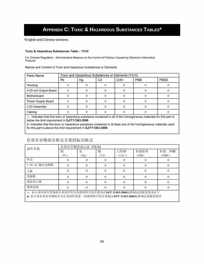
APPENDIX C: TOXIC & HAZARDOUS SUBSTANCES TABLES*
*English and Chinese versions.

This page intentionally left blank.

Thermo Fisher Scientific81 Wyman StreetP.O. Box 9046Waltham, Massachusetts 02454-9046United States
www.thermofisher.com