TWO STAGE PROGRESSIVE GAS BURNERS - Industrial … · RMG Intermittent (at least one stop every 24...
36
The RS burners series covers a firing range from 70 to 2290 kW, and it has been designed for use in low or medium temperature hot water boilers, hot air or steam boilers, diathermic oil boilers. Operation is "two stage progressive"; the burners are fitted with a microprocessor control panel which supplies indication of operation and diagnosis of fault cause. The elevated performance of the fans and combustion head, guarantee flexibility of use and excellent working at all firing rates. The exclusive design ensures reduced dimensions, simple use and maintenance. A wide range of accessories guarantees elevated working flexibility. TS0046UK04 RS SERIES TWO STAGE PROGRESSIVE GAS BURNERS RS 28 81/163 ÷ 325 kW RS 34 MZ 70/125 ÷ 390 kW RS 38 105/232 ÷ 440 kW RS 44 MZ 100/200 ÷ 550 kW RS 50 116/290 ÷ 580 kW RS 64 MZ 150/400 ÷ 850 kW RS 70 192/465 ÷ 814 kW RS 100 232/698 ÷ 1163 kW RS 130 372/930 ÷ 1512 kW RS 190 470/1279 ÷ 2290 kW
Transcript of TWO STAGE PROGRESSIVE GAS BURNERS - Industrial … · RMG Intermittent (at least one stop every 24...
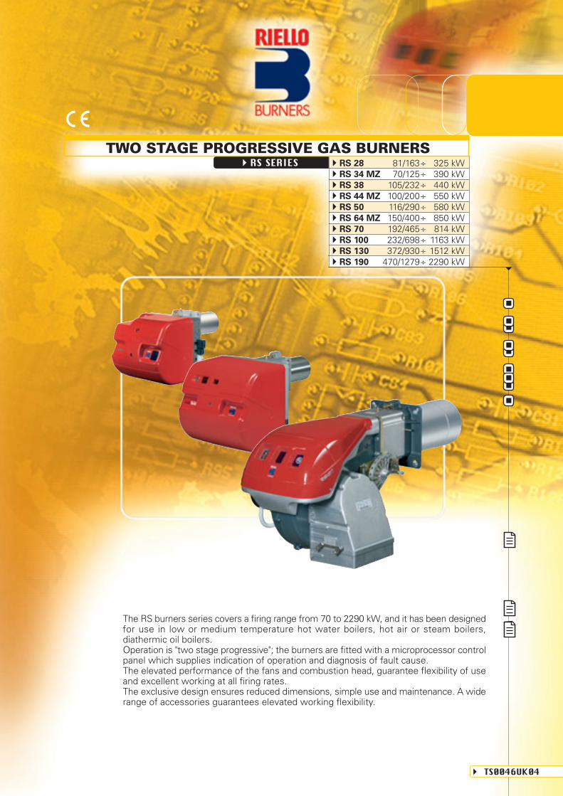
The RS burners series covers a firing range from 70 to 2290 kW, and it has been designedfor use in low or medium temperature hot water boilers, hot air or steam boilers,diathermic oil boilers.Operation is "two stage progressive"; the burners are fitted with a microprocessor controlpanel which supplies indication of operation and diagnosis of fault cause.The elevated performance of the fans and combustion head, guarantee flexibility of useand excellent working at all firing rates.The exclusive design ensures reduced dimensions, simple use and maintenance. A widerange of accessories guarantees elevated working flexibility.
TS0046UK04
RS SERIESTWO STAGE PROGRESSIVE GAS BURNERS
RS 28 81/163÷ 325 kWRS 34 MZ 70/125÷ 390 kWRS 38 105/232÷ 440 kWRS 44 MZ 100/200÷ 550 kWRS 50 116/290÷ 580 kWRS 64 MZ 150/400÷ 850 kWRS 70 192/465÷ 814 kWRS 100 232/698÷ 1163 kWRS 130 372/930÷ 1512 kWRS 190 470/1279÷ 2290 kW

TECHNICAL DATA
Two stage progressive
2 ÷ 1
SQN90
12
0/40
10
0,71
8,6
0,78
25,8
2,02
60
RMG
Intermittent (at least one stop every 24 h)
--
< 40
90/396 - 89/336 - 73/23 - 92/42 EEC
EN 676
Fu
el
/ a
ir d
ata
Ele
ctr
ica
l d
ata
Em
issio
ns
Ap
pro
val
Model
Burner operation mode
Modulation ratio at max. output
Type
Run time
Working temperature
Net calorific value G20 gas
Density gas G20
Output gas G20
Net calorific value G25 gas
Density gas G25
Output gas G25
Net calorific value LPG gas
Density LPG gas
Output LPG gas
Fan
Air temperature
Electrical supply
Auxiliary electrical supply
Control box
Total electrical power
Auxiliary electrical power
Protection level
Motor electrical power
Rated motor current
Motor start current
Motor protection level
Operation
Sound pressure
Sound output
CO Emission
NOx Emission
Directive
Conforming to
Certification
Servo-
motors
kW
Mcal/h
°C min./max.
kWh/Nm3
kg/Nm3
Nm3/h
kWh/Nm3
kg/Nm3
Nm3/h
kWh/Nm3
kg/Nm3
Nm3/h
Type
Max. °C
Ph/Hz/V
Ph/Hz/V
Type
kW
kW
IP
kW
A
A
IP
V1 - V2
I1 - I2
dBA
W
mg/kWh
mg/kWh
Heat output
Ignition
transformer
70/125÷390
60/108÷335
7/13÷39
8/15÷45
3/5÷15
(02)
(04)
(04)
0,6
0,3
40
0,3
3,2
15
40
230V-1x15 kV
1A - 25 mA
70
< 120
CE 0085BR0381
(04)
0,7
0,28
0,42
3,5
17
(06)
0,8
0,35
0,45
2 - 1,4
14 -10
in progress
100/200÷550
86/172÷473
10/20÷55
12/23÷64
4/8÷21
(02)
(04)
40
40
230V-1x15 kV
1A - 25 mA
72
< 120
(03)
0,6
0,42
2,9
11
RS 50
116/290÷581
100/249÷500
11,6/29÷58
13,5/34÷68
4,5/11÷23
(01)
(05)
(03)
0,75
0,12
44
0,65
3 - 1,7
13,8 - 8
54
230V-1x8 kV
1A - 20 mA
72
< 130
RS 28
81/163÷325
70/140÷280
8/16÷32
9,4/19÷38
3/6,5÷12,5
(01)
(03)
(03)
0,37
0,12
44
0,25
2,1
10
40
230V-1x8 kV
1A - 20 mA
68
< 130
(05)
0,56
0,45
2 - 1,2
9,5 - 5,5
CE 0085BR0381
105/232÷440
90/200÷378
10,5/23÷44
12/27÷51
4/9÷17
(01)
(03)
0,12
44
54
230V-1x8 kV
1A - 20 mA
70
< 130
Since the Company is constantly engaged in the production improvement, the aesthetic and dimensional features, thetechnical data, the equipment and the accessories can be changed.This document contains confidential and proprietary information of RIELLO S.p.A. Unless authorised, this informationshall not be divulged, nor duplicated in whole or in part.
(01) Centrifugal with reverse curve blades
(02) Centrifugal with forward curve blades
(03) 1/50/230~(±10%)
(04) 1/50-60/220-230~(±10%)
(05)
(06) 3N/50-60/220-400~(±10%) 3/50-60/220-230~(±10%)
3N/50/230-400~(±10%) 3/50/230~(±10%)
Reference conditions:Temperature: 20°CPressure: 1013.5 mbarAltitude: 100 m a.s.l.Noise measured at a distance of 1 meter.
CE 0085AP0734
2
RS 38
CE 0085AP0733 CE 0085AP0735
RS 44 MZ
150/400÷850
129/344÷731
15/40÷85
17/47÷99
6/16÷33
(02)
(05)
(03)
1,4
0,3
40
1,1
4,8 - 2,8
25 -14,6
40
230V-1x15 kV
1A - 25 mA
76
< 120
RS 64 MZRS 34 MZ

Two stage progressive
2 ÷ 1
15
0/40
10
0,71
8,6
0,78
25,8
2,02
60
1/50/230 ~ (±10%)
RMG
44
54
230V - 1x8 kV
1A - 20 mA
Intermittent (at least one stop every 24 h)
--
< 40
< 130
90/396 - 89/336 - 73/23 - 92/42 EEC
EN 676
Fu
el
/ a
ir d
ata
Ele
ctr
ica
l d
ata
Em
issio
ns
Ap
pro
val
Model
Burner operation mode
Modulation ratio at max. output
Type
Run time
Working temperature
Net calorific value G20 gas
Density gas G20
Output gas G20
Net calorific value G25 gas
Density gas G25
Output gas G25
Net calorific value LPG gas
Density LPG gas
Output LPG gas
Fan
Air temperature
Electrical supply
Auxiliary electrical supply
Control box
Total electrical power
Auxiliary electrical power
Protection level
Motor electrical power
Rated motor current
Motor start current
Motor protection level
Operation
Sound pressure
Sound output
CO Emission
NOx Emission
Directive
Conforming to
Certification
Servo-
motors
kW
Mcal/h
°C min./max.
kWh/Nm3
kg/Nm3
Nm3/h
kWh/Nm3
kg/Nm3
Nm3/h
kWh/Nm3
kg/Nm3
Nm3/h
Type
Max. °C
Ph/Hz/V
Ph/Hz/V
Type
kW
kW
IP
kW
A
A
IP
V1 - V2
I1 - I2
dBA
W
mg/kWh
mg/kWh
Heat output
Ignition
transformer
RS 70
192/465÷814
165/400÷700
19/46,5÷81,4
22/54÷95
7,4/18÷32
(01)
1,4
0,3
1,1
4,8 - 2,8
25 - 14,6
75
C 0085AP0944
(01) Centrifugal with reverse curve blades
(02) Centrifugal with forward curve blades
RS 100
LKS210
232/698÷1163
200/600÷1000
23/70÷116
27/81÷135
9/27÷45
(01)
1,8
0,3
1,5
5,9 - 3,4
27,7 - 16
77
CE 0085AP0945
RS 190
SQN31
470/1279÷2290
405/1100÷1970
47/128÷229
55/149÷266
18/50÷89
(02)
5,5
1
4,5
15,8 - 9,1
126 - 73
83
CE 0085AT0042
RS 130
372/930÷1512
320/800÷1300
37/93÷151
43/108÷176
14,4/36÷59
(01)
2,6
0,4
2,2
8,8 - 5,1
57,2 - 33,2
78,5
CE 0085AP0946
3N/50/230-400~(±10%) 3/50/230~(±10%)
Reference conditions:Temperature: 20°CPressure: 1013.5 mbarAltitude: 100 m a.s.l.Noise measured at a distance of 1 meter.
3

FIRING RATES
Useful working field for choosing the burner
Modulation range (1st stage operation range)
Test conditions conforming to EN 676:Temperature: 20°CPressure: 1000 mbarAltitude: 100 m a.s.l.
0
2
4
6
5
3
1
7
9
8
10
11
kW
12
13
14
0
0
0
20
40
60
50
30
10
70
90
80
100
110
120
130
140
100 200 300 400 500 600 700 800 900 1000 1100 1200 1300 1400 1500 1600 1700 1800 1900 2000 2100
0
2
4
6
5
3
1
7
9
8
10
0
20
40
60
50
30
10
70
90
80
100
100 kW0 200 300 400 500 600 700 800
0
RS 70
RS 100
RS 130
RS 190
RS 50
RS 28
RS 38
RS 34 MZ
RS 44 MZ RS 64 MZ
hP
a (m
bar
)
- 1
mm
H2O
-10
hP
a (m
bar
)
- 1
mm
H2O
-10
Mcal/h
600400200 800 1000 1200 1400 1600 1800 2000 2200 2400
Mcal/h100 200 300 400 500 600 700
4
Example of the variable profilecam on RS 34-44 MZ burners.
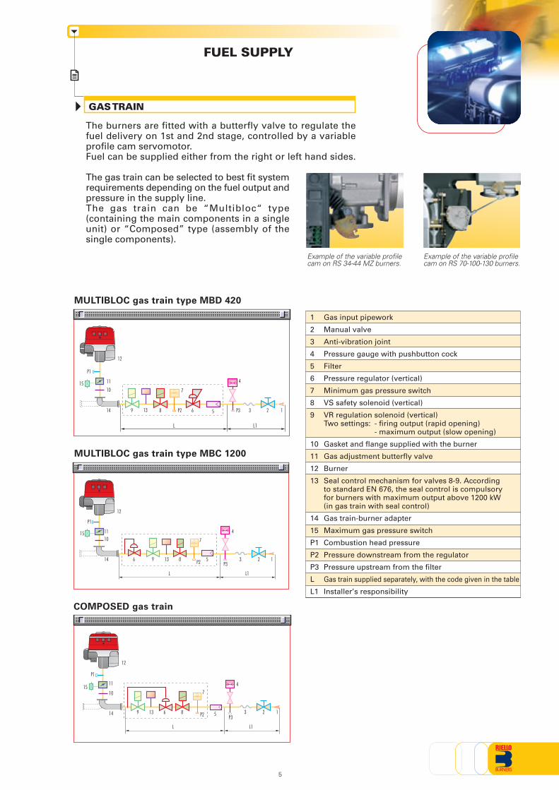
GAS TRAIN
FUEL SUPPLY
Example of the variable profilecam on RS 70-100-130 burners.
Gas input pipework
Manual valve
Anti-vibration joint
Pressure gauge with pushbutton cock
Filter
Pressure regulator (vertical)
Minimum gas pressure switch
VS safety solenoid (vertical)
VR regulation solenoid (vertical)Two settings: - firing output (rapid opening)
- maximum output (slow opening)
Gasket and flange supplied with the burner
Gas adjustment butterfly valve
Burner
Seal control mechanism for valves 8-9. Accordingto standard EN 676, the seal control is compulsoryfor burners with maximum output above 1200 kW(in gas train with seal control)
Gas train-burner adapter
Maximum gas pressure switch
Combustion head pressure
Pressure downstream from the regulator
Pressure upstream from the filter
Gas train supplied separately, with the code given in the table
Installer’s responsibility
1
2
3
4
5
6
7
8
9
10
11
12
13
14
15
P1
P2
P3
L
L1
MULTIBLOC gas train type MBD 420
L L1
MULTIBLOC gas train type MBC 1200
COMPOSED gas train
L L1
The burners are fitted with a butterfly valve to regulate thefuel delivery on 1st and 2nd stage, controlled by a variableprofile cam servomotor.Fuel can be supplied either from the right or left hand sides.
The gas train can be selected to best fit systemrequirements depending on the fuel output andpressure in the supply line.The gas train can be “Multibloc“ type(containing the main components in a singleunit) or “Composed” type (assembly of thesingle components).
12
P1
11
1015
14 9 8 P2 6 P3
4
3 2 15
12
7
12
13
5
P1
15 1110
14 6
L L1
9 13 8
7
5
4
P3P2 3 2 1
P1
1511
10
14 9 13 6 8
7
5
4
P3P2 3 2 1

Gas trains are approved by standard EN 676 together with the burner.
The overall dimensions of the gas train depends on how they are constructed. The following tableshows the maximum dimensions of the gas trains that can be fitted to RS burners, intake and outletdiameters and seal control if fitted.Please note that the seal control can be installed as an accessory, if not already installed on the gas train.The maximum gas pressure of gas train “Multibloc” type is 360 mbar, and that one of gas train“Composed” type is 500 mbar.MULTIBLOC guarantees a range of pressure toward the burner from 3 to 60 mbar. For version DN 65and DN 80 is from 20 to 40 mbar.The range of pressure in the MULTIBLOC with flange can be modified choosing the stabiliser spring(see gas train accessory).
MU
LT
IBLO
C G
AS
TR
AIN
S
Name
MBD 405
MBD 407
MBD 410
MBD 412
MBD 412 CT
MBD 415
MBD 415 CT
MBD 420
MBD 420 CT
MBC 1200 SE 50
MBC 1200 SE 50 CT
Code
3970500 (1)
3970553 (1)3970229 (2)3970599 (1)(3)3970554 (1)3970230 (2)3970600 (1)(3)3970144 (1)3970231 (2)In progress (1)(3)3970197 (1)3970180 (1)3970232 (2)3970250 (1)(3)3970198 (1)3970253 (1)(3)3970181 (1)3970233 (2)3970182 (1)3970234 (2)3970252 (1)(3)3970221 (1)3970225 (1)
Ø i
3/4”
3/4”
1”
1”1/4
1”1/4
1”1/2
1”1/2
2”
2”
2”2”
Ø o
3/4”
3/4”
3/4”
1”1/4
1”1/4
1”1/2
1”1/2
2”
2”
2”2”
X mm
371
371
405
433
433
523
523
523
523
573573
Z mm
120
120
145
145
262
100
227
100
227
161288
Y mm
186
196
217
217
217
250
250
300
300
425425
Seal Control
Accessory
Accessory
Accessory
Accessory
Incorporated
Accessory
Incorporated
Accessory
Incorporated
AccessoryIncorporated
Output pressurerange (mbar)
4 - 20
4 - 20
4 - 20
4 - 20
4 - 20
4 - 33
4 - 33
4 - 33
4 - 33
4 - 604 - 60
Example of gas train“MULTIBLOC”
type MBD
Y
Z X
Øi
Øo
Y
Z X
Øi
Øo
Example of gas train“MULTIBLOC”type MBC 1200
6
(1) Gas Train with 6-pin plug to install for connection to the burner.(2) Gas Train with 6-pin plug installed for connection to the burner.(3) Gas Train S52 type for application with high combustion head pressure drop.

CO
MP
OS
ED
GA
S T
RA
INS
Name
MBC 1900 SE 65 FC
MBC 1900 SE 65 FC CT
MBC 3100 SE 80 FC
MBC 3100 SE 80 FC CT
Code
3970222 (1)
3970226 (1)
3970223 (1)
3970227 (1)
Ø i
DN 65
DN 65
DN 80
DN 80
Ø o
DN 65
DN 65
DN 80
DN 80
X mm
583
583
633
633
Z mm
237
364
240
367
Y mm
430
430
500
500
Seal Control
Accessory
Incorporated
Accessory
Incorporated
20 - 40
20 - 40
20 - 40
20 - 40
Output pressurerange (mbar)
Y
ZX
Øo
Example of gas train“COMPOSED”
type MBC 1900 - 3100
Øi
7
(1) Gas Train with 6-pin plug to install for connection to the burner.

The diagrams indicate the minimum pressure drop of the burners with the various gas trains thatcan be matched with them; at the value of these pressure drop add the combustion chamberpressure.The value thus calculated represents the minimum required input pressure to the gas train.
RS 28
PRESSURE DROP DIAGRAM
NATURAL GAS LPGRS 28
RS 34 MZ RS 34 MZ
Available Gas Train for RS 28 - RS 34 MZ
kcal/h X 1000
10
25
15
20
30
5
0140 150 200 250 280
mb
ar
G25G20
0
5
15
25
30
35
20
10
40
35
40
45
45
50
55
MBD 410
MBD 412 - 412 CT
MBD 407
MBD 415 - 415 CT
kcal/h X 1000
10
25
15
20
30
5
0140 150 200 250 280
mb
ar
LPG
35
40
45
kW300200 250163 325
MBD 410
MBD 412 - 412 CT
MBD 407
ΔP
Com
busti
on h
ead
and
S52
gas
train
Com
busti
on h
ead
and
stand
ard
gas
train
Com
busti
on h
ead
Pres
sure
dro
p
MBD 40
5
kcal/h X 1000200 300250 350
G25G20
0
5
15
25
30
35
20
10
40
MBD 40
7
MBD 412 - 412 CT
MBD 415 - 415 CT
MBD 420 - 420 CT10
25
15
20
30
5
0
mb
ar
LPG
125
45
35
40
ΔP
Com
busti
on h
ead
and
S52
gas
train
Com
busti
on h
ead
and
stand
ard
gas
train
Com
busti
on h
ead
Pres
sure
dro
p
ΔP
Com
busti
on h
ead
and
stand
ard
gas
train
Com
busti
on h
ead
Pres
sure
dro
p
55
50
60
65
kW300 390250 350
108 150
200150
335
55
65
70
75
60
50
80
45
MBD 4
05
MBD 410
kcal/h X 1000200 300250 350
10
25
15
20
30
5
0
mb
ar
125
45
35
40
55
50
60
65
kW300 390250 350
108 150
200150
335
MBD 410
MBD 412 - 412 CT
MBD 415 - 415 CT
MBD 40
7
MBD 4
05
kW300200 250163 325
ΔP
Com
busti
on h
ead
and
gas
train
Com
busti
on h
ead
Pres
sure
dro
p
8
Gas train
MBD 412 CT
MBD 415
MBD 415 CT
MBD 420
MBD 420 CT
Code3970197 (1)3970180 (1)3970232 (2)3970198 (1)3970181 (1)3970233 (2)3970182 (1)3970234 (2)
Adapter----
3000822300082230008223000822
Seal ControlIncorporatedAccessoryAccessory
IncorporatedAccessoryAccessory
IncorporatedIncorporated
Code3970500 (1)3970553 (1)3970229 (2)3970599 (1)(3)3970554 (1)3970230 (2)3970600 (1)(3)3970144 (1)3970231 (2)
Adapter3000824300082430008243000824300082430008243000824
-- (1) Gas Train with 6-pin plug to install for connection to the burner.
(2) Gas Train with 6-pin plug installed for connection to the burner.(3) Gas Train S52 type for application with high combustion head pressure drop
Gas train
MBD 405
MBD 407
MBD 410
MBD 412
Seal ControlAccessoryAccessoryAccessoryAccessoryAccessoryAccessoryAccessoryAccessoryAccessory

NATURAL GAS LPG
RS 38
RS 44 MZ RS 44 MZ
Available Gas Train for RS 38 - RS 44 MZ
kcal/h X 1000
10
25
15
20
30
5
0
200 300250 350 378
mb
ar
LPG
MBD 410
MBD 412 - 412 CT
MBD 415 - 415 CT
kW300 440400250 350232
400
45
35
40
MBD 407ΔP
Com
busti
on h
ead
and
S52
gas
train
Com
busti
on h
ead
and
stand
ard
gas
train
Com
busti
on h
ead
Pres
sure
dro
p
55
50
60
65
MBD 40
5
G25G20
0
20
40
50
10
60
mb
ar
LPGΔP
Com
busti
on h
ead
and
S52
gas
train
Com
busti
on h
ead
and
stand
ard
gas
train
Com
busti
on h
ead
Pres
sure
dro
p
250 300 350 400 473kcal/h X 1000
MBD
410
MBD 412 - 412 CT
MBD 415 - 415 CT
MBD 420 - 420 CT
kW400 550500350 450300
mb
arΔP
Com
busti
on h
ead
and
stand
ard
gas
train
Com
busti
on h
ead
Pres
sure
dro
p
10
20
0
30
40
50
60
70
80
90
100
30
80
100
110
70
120
90
250200
172 200 250 300 350 400 473kcal/h X 1000
MBD 407
MBD 412 - 412 CTMBD 415 - 415 CT
kW400 550500350 450300
10
20
0
30
40
50
60
70
80
90
100
250200
172 200
MBD 405
MBD 410
RS 38
kcal/h X 1000
10
25
15
20
30
5
0
200 300250 350 378
mb
ar
G25G20
0
5
15
25
30
35
20
10
40MBD 410
MBD 412 - 412 CT
MBD 415 - 415 CT
MBD 420 - 420 CT
ΔP
Com
busti
on h
ead
and
gas
train
Com
busti
on h
ead
Pres
sure
dro
p
kW300 440400250 350232
9
Gas train
MBD 412 CT
MBD 415
MBD 415 CT
MBD 420
MBD 420 CT
Code3970197 (1)3970180 (1)3970232 (2)3970198 (1)3970181 (1)3970233 (2)3970182 (1)3970234 (2)
Adapter----
3000822300082230008223000822
Seal ControlIncorporatedAccessoryAccessory
IncorporatedAccessoryAccessory
IncorporatedIncorporated
Code3970500 (1)3970553 (1)3970229 (2)3970599 (1)(3)3970554 (1)3970230 (2)3970600 (1)(3)3970144 (1)3970231 (2)
Adapter3000824300082430008243000824300082430008243000824
-- (1) Gas Train with 6-pin plug to install for connection to the burner.
(2) Gas Train with 6-pin plug installed for connection to the burner.(3) Gas Train S52 type for application with high combustion head pressure drop
Gas train
MBD 405
MBD 407
MBD 410
MBD 412
Seal ControlAccessoryAccessoryAccessoryAccessoryAccessoryAccessoryAccessoryAccessoryAccessory

RS 50
NATURAL GAS LPG
RS 64 MZ
RS 50
RS 64 MZ
Gas train
MBD 407
MBD 410
MBD 412
MBD 412 CT
Code3970553 (1)3970599 (1)(3)
3970554 (1)
3970144 (1)3970197 (1)
Adapter3000824+3000843
3000824+300084330008433000843
Seal Control
Accessory
Accessory
AccessoryIncorporated
Gas train
MBD 415
MBD 415 CT
MBD 420
MBD 420 CT
MBC 1200 SE
MBC 1200 SE CT
Code3970180 (1)3970198 (1)3970181 (1)3970182 (1)3970221 (1)3970225 (1)
Adapter30008433000843
----
Seal ControlAccessory
IncorporatedAccessory
IncorporatedAccessory
Incorporated
10
25
15
20
45
5
0
30
35
40
50
mb
ar
249 300 350 400 450kcal/h X 1000
500
G25G20
0
20
40
50
30
10
60
5
25
45
55
35
15
MBD 410
MBD 412 - 412 CT
MBD 415 - 415 CT
MBD 420 - 420 CT
ΔP
MBC 1200 SE - 1200 SE CT
kcal/h X 1000
mb
ar
10
20
30
kW
300 600500400
500 600
0
800400 700
40
50
850
G25
0
20
40
50
30
10
60
MBD 415 - 415 CT
MBD 420 - 420 CT
ΔP
60
70
70
80
90
MBC 1200 SE - 1200 SE CT
G20
10
20
0
30
40
50
mb
ar
249 300 350 400 450kcal/h X 1000
500
LPG
MBD 410
MBD 412 - 412 CT
MBD 415 - 415 CT
MBD 420 - 420 CT
ΔP
kW400 550500350 450290 580
60
MBD 407
Com
busti
on h
ead
and
S52
gas
train
Com
busti
on h
ead
and
stand
ard
gas
train
Com
busti
on h
ead
Pres
sure
dro
p
70
80
90
100
Com
busti
on h
ead
and
stand
ard
gas
train
Com
busti
on h
ead
Pres
sure
dro
p
800
300
344 731
MBD 41
2 - 41
2 CT
kcal/h X 1000
mb
ar
10
20
30
kW
300 600500400
500 600
0
800400 700
40
50
850
MBD 415 - 415 CT
MBD 420 - 420 CT
ΔP
60
70
LPG
800
300
344 731
MBD 412 - 412 CT
Com
busti
on h
ead
and
S52
gas
train
Com
busti
on h
ead
and
stand
ard
gas
train
Com
busti
on h
ead
Pres
sure
dro
p
80
90
100
110
120
130
140
MBD 40
7
MBD 410
kW400 550500350 450290 581
Com
busti
on h
ead
and
gas
train
Com
busti
on h
ead
Pres
sure
dro
p
10
Gas train
MBD 407
MBD 410
MBD 412
MBD 412 CT
MBD 415
Code3970553 (1)3970599 (1)(3)3970554 (1)3970600 (1)(3)3970144 (1)In progress (1)(3)3970197 (1)3970180 (1)3970250 (1)(3)
Adapter3000824300082430008243000824
-----
Seal ControlAccessoryAccessoryAccessoryAccessoryAccessoryAccessory
IncorporatedAccessoryAccessory
Gas train
MBD 415 CT
MBD 420
MBD 420 CT
MBC 1200 SE
MBC 1200 SE CT
Code3970198 (1)3970253 (1)(3)3970181 (1)3970182 (1)3970252 (1)(3)3970221 (1)3970225 (1)
Adapter--
30008223000822300082230008223000822
Seal ControlIncorporatedIncorporatedAccessory
IncorporatedIncorporatedAccessory
Incorporated(1) Gas Train with 6-pin plug to install for connection to the burner.(3) Gas Train S52 type for application with high combustion head pressure drop
(1) Gas Train with 6-pin plug to install for connection to the burner.(3) Gas Train S52 type for application with high combustion head pressure drop

NATURAL GAS LPG
RS 100 RS 100
RS 70 RS 70
Gas train
MBD 412
MBD 412 CT
MBD 415
MBD 415 CT
Code3970144397019739701803970198
Adapter3000843300084330008433000843
Seal ControlAccessory
IncorporatedAccessory
Incorporated
Gas train
MBD 420
MBD 420 CT
MBC 1200 SE
MBC 1200 SE CT
Code3970181397018239702213970225
Adapter----
Seal ControlAccessory
IncorporatedAccessory
Incorporated
Code3970221397022539702223970226
Adapter--
30008253000825
Seal ControlAccessory
IncorporatedAccessory
Incorporated
Gas train
MBD 415
MBD 415 CT
MBD 420
MBD 420 CT
Code3970180397019839701813970182
Adapter30008433000843
--
Seal ControlAccessory
IncorporatedAccessory
Incorporated
Gas train
MBC 1200 SE
MBC 1200 SE CT
MBC 1900 SE
MBC 1900 SE CT
kcal/h X 1000
mb
ar
10
20
30
kW
600 900800700 1000
800 900
0
1100700 1000
40
50
1163
G25
0
20
40
50
30
10
60
MBD 415 - 415 CT
MBD 420 - 420 CT
ΔP
kcal/h X 1000
mb
ar
10
20
30
kW
600 900800700 1000
800 900
0
1100700 1000
40
50
1163
LPG
MBD 415 - 415 CT
MBD 420 - 420 CT
ΔP
Com
busti
on h
ead
and
gas
train
Com
busti
on h
ead
Pres
sure
dro
p
Com
busti
on h
ead
and
gas
train
Com
busti
on h
ead
Pres
sure
dro
p
60
70
70
80
90
MBC 1900 SE - 1900 SE CTMBC 1200 SE - 1200 SE CT
60
70G20
MBC 1900 SE - 1900 SE CT
MBC 1200 SE - 1200 SE CT
kcal/h X 1000
mb
ar
30
20
40
0
10
50
400 500 600 700
G25G20
0
20
40
50
30
10
60
MBD 415 - 415 CT
MBD 420 - 420 CT
ΔP
kcal/h X 1000
mb
ar
30
20
40
0
10
50
400 500 600 700
LPG
MBD 420 - 420 CT
ΔP
MBD 415 - 415 CT
kW600500 700465 814
MBC 1200 SE - 1200 SE CTMBC 1200 SE - 1200 SE CT
MBD 412 - 412 CT
kW600500 700465 814
Com
busti
on h
ead
and
gas
train
Com
busti
on h
ead
Pres
sure
dro
p
Com
busti
on h
ead
and
gas
train
Com
busti
on h
ead
Pres
sure
dro
p
11

Please contact the Riello Burner Technical Office for different pressure levels from those above indicatedand refer to the technical manual for the correct choice of the spring.
In LPG plants, Multibloc gas trains do not operate below 0°C. They are only suitable for gaseous LPG (liquidhydrocarbons destroy the seal materials).
MBC 1200 gas train: the minimum operating pressure (*) is higher or equal to 10 mbar. The gas train hasto be installed next to the burner (if needed, only with the adapters listed in the catalogue) and it has tooperate in its own working field.
MBC 1900-3100 gas train: the minimum operating pressure (*) is higher or equal to 15 mbar. The gas trainhas to be installed next to the burner (if needed, with the adapters listed in the catalogue) and it has tooperate in its own working field.
(*) it is the upstream gas train pressure in full load operation conditions.
note
RS 190
mb
ar
20
80
40
60
100
kW
11001000 13001200
1700 1800
0
15001400 1600
1400 1500
19001279 2290
G25G20
0
40
80
100
60
20
120
kcal/h X 1000
MBC 1900 SE 65 FC - 1900 SE 65 FC CT
MBC 3100 SE 80 FC - 3100 SE 80 FC CT
MBD 420 - 420 CT
1600 1700 1800 1900
1200 2000 2100
2000
RS 190
mb
ar
20
80
40
60
100
kW
11001000 13001200
1700 1800
0
15001400 1600
1400 1500
19001279 2290
LPG
kcal/h X 1000
MBD 415 - 415 CT
MBD 420 - 420 CT
1600 1700 1800 1900
1200 2000 2100
2000
140
MBC 1200 SE 50 FC - 1200 SE 50 FC CT
MBC 1900 SE 65 FC - 1900 SE 65 FC CT
MBC 3100 SE 80 FC - 3100 SE 80 FC CTMBC 1200 SE 50 FC - 1200 SE 50 FC CT
Code
3970225
3970222
3970227
3970223
3970228
Adapter
-
3000825
3000825
3000826
3000826
Seal Control
Incorporated
Accessory
Incorporated
Accessory
Incorporated
Gas train
MBD 415
MBD 415 CT
MBD 420
MBD 420 CT
MBC 1200 SE 50
Code
3970180
3970198
3970181
3970182
3970221
Adapter
3000843
3000843
-
-
-
Seal Control
Accessory
Incorporated
Accessory
Incorporated
Accessory
Gas train
MBC 1200 SE 50 CT
MBC 1900 SE 65 FC
MBC 1900 SE 65 FC CT
MBC 3100 SE 80 FC
MBC 3100 SE 80 FC CT
ΔP
Com
busti
on h
ead
and
gas
train
Com
busti
on h
ead
Pres
sure
dro
p
ΔP
Com
busti
on h
ead
and
gas
train
Com
busti
on h
ead
Pres
sure
dro
p
RS 130 RS 130
Code
3970225
3970222
3970226
3970223
3970227
Adapter
-
3000825
3000825
3000826
3000826
Seal Control
Incorporated
Accessory
Incorporated
Accessory
Incorporated
Gas train
MBD 415
MBD 415 CT
MBD 420
MBD 420 CT
MBC 1200 SE
Code
3970180
3970198
3970181
3970182
3970221
Adapter
3000843
3000843
-
-
-
Seal Control
Accessory
Incorporated
Accessory
Incorporated
Accessory
Gas train
MBC 1200 SE CT
MBC 1900 SE
MBC 1900 SE CT
MBC 3100 SE
MBC 3100 SE CT
mb
ar
kW
900800 11001000
1300 140011001000 1200
1200 1300
930 1512
kcal/h X 1000
G25G20ΔP
mb
ar
kW
900800 11001000
1300 1400
0
11001000 1200
1200 1300
930 1512
kcal/h X 1000
LPG
MBD 415 - 415 CT
MBD 420 - 420 CT
ΔP
MBC 1200 SE - 1200 SE CT
Com
busti
on h
ead
and
gas
train
Com
busti
on h
ead
Pres
sure
dro
p
Com
busti
on h
ead
and
gas
train
Com
busti
on h
ead
Pres
sure
dro
p
10
40
20
30
50
0
60
70
80
90
100
110
0
20
40
50
30
10
60
70
80
90
100
110
120
130
140
MBD 415 - 415 CT
MBD 420 - 420 CT
MBC 3100 SE - 3100 SE CTMBC 1900 SE - 1900 SE CTMBC 1200 SE - 1200 SE CT
10
40
20
30
50
60
70
80
90
100
110
NATURAL GAS LPG
12

SELECTING THE FUEL SUPPLY LINES
0,1 0,2 0,3 0,4 0,5 0,6 0,7 0,8 1 2 3 4 5 106 20
50 60 10080 200 400 800 1000600
3
69
12152230
45 61 76 95 122 152 V
PRESSURE DROP (mbar)
1 2 3 4 5 6 7 8 10 20 30 40
PIPE DIAMETER
1,4
PIPE LENGTH (m)
1/2
3/4
1"
1" 1/2
6"
1" 1/4
4"
3"2" 1/22"
= Gas output Nmc/h
f1 - G20
= 0,62 - G251,18 - G31{
fV
15,34
Figure A
The following diagram enables pressure drop in a pre-existing gas line to be calculated and to select thecorrect gas train.The diagram can also be used to select a new gas line when fuel output and pipe length are known. Thepipe diameter is selected on the basis of the desired pressure drop. The diagram uses methane gas asreference; if another gas is used, conversion coefficient and a simple formula (on the diagram) transformthe gas output to a methane equivalent (refer to figure A). Please note that the gas train dimensions musttake into account the back pressure of the combustion chamber during operations.
Control of the pressure drop in an existing gas line or selecting a new gas supply line.The methane output equivalent is determined by the formula fig. A on the diagram and the conversioncoefficient.
Once the equivalent output has been determined on the delivery scale ( ), shown at the top of thediagram, move vertically downwards until you cross the line that represents the pipe diameter; at thispoint, move horizontally to the left until you meet the line that represents the pipe length.Once this point is established you can verify, by moving vertically downwards, the pipe pressure dropof on the botton scale below (mbar).By subtracting this value from the pressure measured on the gas meter, the correct pressure value willbe found for the choice of gas train.
Example: - gas used G25- gas output 9.51 mc/h- pressure at the gas meter 20 mbar- gas line length 15 m- conversion coefficient 0.62 (see figure A)
- equivalent methane output = 9.51 = 15.34 mc/h0.62
- once the value of 15.34 has been identified on the output scale ( ), moving vertically downwards youcross the line that represents 1" 1/4 (the chosen diameter for the piping);
- from this point, move horizontally to the left until you meet the line that represents the length of 15 mof the piping;
- move vertically downwards to determine a value of 1.4 mbar in the pressure drop botton scale;- subtract the determined pressure drop from the meter pressure, the correct pressure level will be found
for the choice of gas train;
- correct pressure = ( 20-1.4 ) = 18.6 mbar
V
V
V
13

The RS 34 MZ and RS 44 MZ are realised with a new structure made by an innovative technologybased on a new fibreglass reinforced polyamide material, with high thermal and mechanical characteristics,instead of the traditional aluminium.This allows big advantages in terms of lay-out rationalisation, weight and dimensions reduction.In order to guarantee the correctexercise temperature for theinternal burner components inevery working conditions, thenew structure includes aninnovative patented coolingtechnology.Between the burner front baseand the reinforcing steel frontplate, had been create an aircavity offering an high thermalinsulation against the front boilerreflection heat, and to furtherimprove the insulation efficiencythe innovative HCS (HousingCooling System) technologyhad been developed. Inside thefront base cavity an air circulationis activated with continuous airvolume refresh to obtain anactive cooling system and avoidany heat transfer to the electricalcomponent housing.
The ventilation circuit produces lownoise levels with high performancepressure and air output, inspite of thecompact dimensions.
On RS 28-38-50-70-100-130 models, the use of reverse curve bladesand sound-proofing material keeps noise level very low.In the RS 34 MZ - 44 MZ - 64 MZ - 190 models, noise has been reducedby the special design of the air suction circuit.
A variable profile cam connects the fuel and air regulations, to obtaina perfect control of combustion during the change of stage. When theburner is not operating the servomotor closes completely the airdamper to reduce heat dispersion from the boiler.A minimum air pressure switch stops the burner when there is aninsufficient quantity of air at the combustion head.
VENTILATION
Example of the air damper onRS 28 - 38 - 50 burners
14
Example of HCS (Housing Cooling System) working concept

Different lengths of thecombustion head can bechosen for the RS series ofburners.
The choice depends on the thickness of the front panel and thetype of boiler.
Depending on the type of generator, check that the penetration ofthe head into the combustion chamber is correct.
The internal positioning of the combustion head can easily beadjusted to the maximum defined output by adjusting a screwfixed to the flange.
COMBUSTION HEAD
Example of a RS burner combustionhead
Flame dimensions
Example:Burner thermal output = 2000 kW;L flame (m) = 2,7 m (medium value);D flame (m) = 0,8 m (medium value)
D
L
Burner output (MW)
3
1
2
4
Flam
e le
ng
ht
(m)
Flam
e d
iam
eter
(m
)
0 0
0,5
1
1,5
2
0 21 3 4
D max
D min
L max
L min
15

ADJUSTMENT
BURNER OPERATION MODE
On “two stage” operation, the burnergradually adapts the output to therequested level, by varying betweentwo pre-set levels (see picture A).
All RS series burners are fitted with a new microprocessor control panel for the supervision duringintermittent operation.For helping the commissioning and maintenance work, there are two main elements:
The lock-out reset button is the central operating element for resetting the burner controland for activating / deactivating the diagnostic functions.
The multi-color LED is the central indication element for visual diagnosis and interfacediagnosis.
Both elements are located under the transparent cover of lock-out reset button, as showed below.
There are two diagnostic choices, for indication of operation and diagnosis of fault cause:
- visual diagnosis :
- interface diagnosis : by the interface adapterand a PC with dedicateds o f t w a r e o r b y apredisposed flue gasanalyzer (see paragraphaccessories).
Switch
Switch
COMPUTER
or
FLUE GASANALYSER
INTERFACE ADAPTER
Picture A
Ou
tpu
tC
on
tro
lled
var
iab
le
Two stage operation
bar°C
MAX
MIN
Time
Time
16

RS 28 - 34 MZ - 38 - 44 MZ - 50 - 64 MZ - 100 - 130 - 190
START UP CYCLE
Indication of operation:In normal operation, the various status areindicated in the form of colour codes accordingto the table below.The interface diagnosis (with adapter) can beactivated by pressing the lock-out button for> 3 seconds.
Color code table
Operation status
Stand-byPre-purgingIgnition phaseFlame OKPoor flameUndervoltage, built-in fuseFault, alarmFlame simulation
Color code table
LED off
Diagnosis of fault causes:After lock-out has occurred, the red signal lamp is steady on. In this status, the visual fault diagnosisaccording to the error code table can be activated by pressing the lock-out reset button for > 3 seconds.The interface diagnosis (with adapter) can be activated by pressing again the lock-out button for > 3seconds.
The flashing of red LED are a signal with this sequence:
(e.g. signal with n° 3 flashes – faulty air pressure monitor)
LED off3 sec. 3 sec. 3 sec.
time (s)
43 45
28
46
53
3
2
3
Off Yellow Green
0 s The burner begins the firing cycle.2 s The motor starts: pre-purge phase.43 s Ignition electrode sparks; safety valve VS and
adjustment valve VR open.45 s The spark goes out.53 s Output can be increased; start up cycle is concluded.
M
0
2°1°
0
2°1°
TL
TR
VRVS
RMGLED*
0
M
17
Error code table
Possible cause of fault Flash code
2 flashes
3 flashes
4 flashes
7 flashes
10 flashes
No establishment of flame at the end of safety time : - faulty or soiled fuel valves- faulty or soiled flame detector- poor adjustment of burner, no fuel- faulty ignition equipment
Faulty air pressure monitor
Extraneous light or simulation of flame on burner start up
Loss of flame during operation : - faulty or soiled fuel valves- faulty or soiled flame detector- poor adjustment of burner
Wiring error or internal fault

BURNER WIRING
Example of plugs andsockets for electricalconnections for the
RS 28-38-50 models
The following table shows the supply lead sections and the type of fuse to be used.
All models of the RS burner series have an easily accessible controlpanel for the electrical components housing and wiring.In particular the new RS 34-44 MZ models, thanks to the new structureconcept, have a extremely clean electrical layout to optimise thecommissioning and maintenance speed.On these models the electrical connection are done by a Plug&Socketsystem, accessible from the external of the cover, and some of themain components as the servomotor, the air pressure switch and thegas max pressure switch (accessory) are connected to the burnerelectrical wiring trough plugs & sockets system in order to facilitatethe connection in case of maintenance.The electrical wiring of all RS burner models are very easy to dofollowing the wiring diagrams included in the instruction handbook.Electrical connections must be made by qualified and skilled personnel,according to the local norms.
RS 28 RS 38
230V
T61,5
400V
T61,5
230V
T61,5
400V
T61,5
RS 50
230V
T61,5
400V
T61,5
230V
T101,5
400V
T61,5
Model
A
mm2
FL
230V
T61,5
RS 34 MZ
230V
T61,5
RS 44 MZ RS 64 MZ
230V
T61,5
RS 44 MZRS 38
230V
T61,5
18
RS 100 RS 130
230V
T161,5
400V
T101,5
230V
T161,5
400V
T101,5
RS 190
230V
T252,5
400V
T202,5
Model
A
mm2
FL
RS 70
230V
T101,5
400V
T61,5
Example ofelectricalcomponentshousing andPlug&Socketsystem forelectricalconnection ofRS 34-44 MZ

EMISSIONS
The emission data has been measured in the various models at maximumoutput, according to EN 676 standard.
The NOx emissions of RS 34-44-64 MZ models are conforming to the class 2of EN 676.
CO EMISSIONS
mg
/kW
h
0
10
20
30
40
50
RS 28 RS 38 RS 50 RS 70 RS 100 RS 130 RS 190
NO2 EMISSIONS
mg
/kW
h
0
50
100
150
75
25
RS 28 RS 38 RS 50 RS 70 RS 100 RS 130 RS 190
125
NOISE EMISSIONS
dB
(A)
0
20
40
60
80
100
RS 28 RS 38 RS 50 RS 70 RS 100 RS 130 RS 190
RS 34 MZ RS 44 MZ RS 64 MZ
RS 34 MZ RS 44 MZ RS 64 MZ
RS 34 MZ RS 44 MZ RS 64 MZ
19

OVERALL DIMENSIONS (mm)
BURNERS
RS 34 MZ - 44 MZ
RS 70 - 100 - 130 - 190
RS 28 - 38 - 50
Model A D H
RS 28
RS 34 MZ
RS 38
RS 44 MZ
RS 50
476442476442476
352305352305352
164138164138164
G(1)
580508580508580
140140140152152
G
351351351351351
F
216216216216216
------
O
810780810780810
I
168177168177168
L
474422474422474
E
1”1/21”1/21”1/21”1/21”1/2
M
1088410884108
N
367-
367-
367
S
A
D
O
GG (1)
E
H
I
N
LM
(1) dimension with extended head
F
S
O - O (1)
A
D
B C
L
E
I
G - G (1)F
N
M
H
O
RS 64 MZ
A
D
GG (1)
E
H
I
N
ML
F
O
B
A
D
GG (1)
E
H
I
N
ML
F
20
Model A B DC H
300296312338366
533511527553681
352430430430430
-215215215315
222214214214230
G(1)
640840840840856
179179179189222
G
385385385415530
F
250250250280372
------
O
8101161116111611312
O(1)
-129612961296
-
-----
-I
221221221221186
L
490555555555555
E
2”2”2”2”2”
M
134134134134150
N
(1) dimension with extended head
RS 64 MZ
RS 70
RS 100
RS 130
RS 190

PACKAGING
X (1)
Z
Y
BURNER – BOILER MOUNTING FLANGE
Ø
D2
45°
45°
D1
ØD2160160160160160185185185195230
M8M8M8M8M8M12M12M12M12M16
224224224224224
275-325275-325275-325275-325325-368
D1
Y kg
38324033414270737682
RS 28
RS 34 MZ
RS 38
RS 44 MZ
RS 50
RS 64 MZ
RS 70
RS 100
RS 130
RS 190
Model Z
RS 28
RS 34 MZ
RS 38
RS 44 MZ
RS 50
RS 64 MZ
RS 70
RS 100
RS 130
RS 190
Model
X (1)
1200100012001000120012001410141014101410
502485502485502580655655655655
520500520500520520692692692985
(1) dimension with standard and extended head
21

INSTALLATION DESCRIPTION
All the burners have slide bars, for easier installationand maintenance.
After drilling the boilerplate, using the supplied gasketas a template, dismantle the blast tube from the burnerand fix it to the boiler.
Adjust the combustion head.
Fit the gas train, choosing this on the basis of themaximum output of the boiler and considering theenclosed diagrams.
Refit the burner casing to the slide bars.
Close the burner, sliding it up to the flange.
Make the electrical connections to the boiler followingthe wiring diagrams included in the instructionhandbook.
Turn the motor to check rotation direction (if it is athree-phase motor).
Perform a first ignition calibration on the gas train.
On start up, check:- Gas pressure at the combustion head (to max. and
min. output)- Combustion quality, in terms of unburned substances
and excess air.
Installation, start up and maintenance must be carriedout by qualified and skilled personnel.All operations must be performed in accordance with thetechnical handbook supplied with the burner.
BURNER SETTING
ELECTRICAL CONNECTIONS AND START-UP
BURNER MAINTENANCE
The maintenance of RS burners is very simple thanksto the sliding bars system that allows an easy accessto the internal components.
In particular the RS 34-44 MZ models have a newsliding bars system to make easier the access to thecombustion head.
The RS 190 has new reinforced sliding bars that makevery strong the burner structure during maintenance.
22

BURNER ACCESSORIES
Extended head kit
“Standard head” burners can be transformed into “extended head” versions, by using the special kit.The KITS available for the various burners, giving the original and the extended lengths, are listedbelow.
Kit code
RS 28RS 34 MZRS 38RS 44 MZRS 50RS 64 MZRS 70RS 100RS 130RS 190
Burner
3010076
3010428
3010077
3010429
3010078
3010427
3010117
3010118
3010119
3010443
‘Extended head’length (mm)
351351351351351385385385415530
216216216216216250250250280372
‘Standard head’length (mm)
Spacer kit
If burner head penetration into the combustion chamber needs reducing, varying thickness spacersare available, as given in the following table:
RS 28 - 34 MZ - 38 - 44 MZ - 50RS 64 MZ - 70 - 100 - 130RS 190
Burner Kit code
3010095
3010129
3000722
Continuous ventilation kit
If the burner requires continuous ventilation in the stages without flame, a special kit is available asgiven in the following table:
RS 28 - 38 - 50 - 70 - 100 - 130 - 190Burner Kit code
3010094
S
Spacer thickness S (mm)
90135102
Extended head kit
Continuous ventilation kit
23
Spacer kit

Post-ventilation kit
To prolong ventilation for approximately 5 seconds after opening of thermostats chain, a special kitis available.
RS 28 - 38 - 50 - 70 - 100 - 130 - 190Burner Kit code
3010004
RS 28RS 34 MZRS 38RS 44 MZRS 50RS 64 MZRS 70RS 100RS 130RS 190
Burner
LPG kit
Kit code for‘extended head’
Kit code for‘standard head’
3010089
3010423
3010090
3010424
3010165
3010435
3010098
3010100
3010102
-
LPG kit
For burning LPG gas, a special kit is available to be fitted to the combustion head on the burner, asgiven in the following table:
3010089
3010423
3010090
3010424
3010165
3010434
3010097
3010099
3010101
3010166
24
Post-ventilation kit
Connection flange kit
A kit is available for use where the burner opening on the boiler is of excessive diameter.
RS 28 - 34 MZ - 38 - 44 MZ - 50Burner Kit code
3010138
Connection flange kit
Sound proofing box
If noise emission needs reducing even further, sound-proofing boxes are available, as given in thefollowing table:
Sound proofing box
(*) according to EN 15036-1 standard
Burner Box code
3010403
3010404
C1/3
C4/5
Box type
10
10
Average noisereduction [dB(A)](*)
RS 28 - 34 MZ - 38 - 44 MZRS 50 - 64 MZ - 70 - 100 - 130RS 190

Status Panel kit
The RS burners can be equipped with an exclusive electronic device “Status Panel” which continuouslymonitors and displays all the burner operational modes and picks up any anomalies during theoperational cycle.
RS 28 - 38 - 50 - 70 - 100 - 130 - 190Burner Kit code
3010322
Burner Kit code
Vibration reduction kit
The kit allow you to improve flame stability in some applications, where the boiler/flue assemblyis liable to resonate.
Vibration reduction kit
RS 28 TC - RS 28 TLRS 38 TC - RS 38 TLRS 50 TC - RS 50 TLRS 70 TC - RS 70 TLRS 100 TC - RS 100 TLRS 130 TCRS 130 TLRS 190 TC
RS 28RS 38RS 50RS 70RS 100RS 130RS 190
Burner
Town gas kit
Town gas kit
For burning Town gas, a special kit is available:
3010283
3010284
3010285
3010286
3010287
3010288
3010297
(*) Without CE certification
3010198
3010199
3010200
3010201
3010202
3010373
3010374
3010375
Kit code forstandard head (*)
3010283
3010284
3010285
3010286
3010287
3010288
3010297
Kit code forextended head (*)
Status Panel kit
25

Ground fault interrupter kit
A “Ground fault interrupter kit” is available as a safety device for electrical system fault.
RS 28 - 34 MZ - 38 - 44 MZ - 50 - 64 MZRS 70 - 100 - 130 - 190
Burner Kit code
3010321
3010329
Gas max pressure switch
If necessary a Gas max pressure Switch kit is available and connectable to the burner electrical wiringtrough Plugs & Sockets system.
Burner Code
3010418
Gas max pressure switch
RS 34 MZ - 44 MZ
Volt free contact kit
A volt free contact kit is available for installation onto the burner. This can be used for a remote interfacebetween burner operating signals, for example, burner run or lockout indication.
Burner Kit code
3010419
Volt free contact kit
RS 34 MZ - 44 MZ
PC interface kit
To connect the flame control panel to a personal computer for the transmission of operation, faultsignals and detailed service information, an interface adapter with PC software are available.
Burner Kit code
3002719
PC interface kit
RS 28 - 34 MZ - 38 - 44 MZ - 50 - 64 MZRS 70 - 100 - 130 - 190
Ground fault interrupter kit
26
50 45
40
5
3530
2520
10
15
2,5

GAS TRAIN ACCESSORIES
Adapters
When the diameterof the gas train isdifferent from theset diameter of theburners, an adaptermust be f i t tedbetween the gastrain and the burner.The following tablelists the adapters forvarious burners.
Adapters
Burner Gas train Dimensions Adapter code
1"1/23/4"
2" 1"1/2
1"1/23/4"
1"1/23/4"
2" 1"1/2
1"1/23/4"
2" 1"1/2
1"1/23/4"
2" 1"1/2
1"1/23/4"
2"1"1/2
2"1"1/2
1"1/2 2"
1"1/2 2"
1"1/2 2"
RS 28
RS 34 MZ
RS 38
RS 44 MZ
RS 50
MBD 405 - 407 - 410
MBD 405 - 407 - 410
MBD 420
MBD 405 - 407 - 410
MBD 420
MBD 405 - 407 - 410
MBD 420
MBD 407 - 410
MBD 420 - MBC 1200
3000824
3000824
3000822
3000824
3000822
3000824
3000822
3000824
3000822
RS 64 MZ
RS 70
RS 100
RS 130
RS 190
MBD 407 - 410
MBD 412 - 415
MBD 412 - 415
MBC 1900
MBC 3100
MBD 415
MBC 1900
MBC 3100
MBD 415
MBC 1900
MBC 3100
MBD 415
MBC 1900
MBC 3100
3000824+
3000843
3000843
3000843
3000825
3000826
3000843
3000825
3000826
3000843
3000825
3000826
3000843
3000825
3000826
1"1/2
2"
DN 65 2"1/2
DN 80 2"1/2 2"
DN 80 2"1/2 2"
1"1/2
2"
DN 65 2"1/2
1" 1/2 2"
DN 65 2"1/2
2"
1"1/2
DN 80 2"1/2 2"
DN 80 2"1/2 2"
1"1/2
2"
DN 65 2"1/2
27

Stabiliser springs
Stabiliser spring
Accessory springs are available to vary the pressure range of the gas train stabilisers. The followingtable shows these accessories with their application range.
Please refer to the technical manual for the correct choice of spring.
Gas train Spring codeSpring
Seal control kit
To test the valve seals on the gas train, a special “seal control kit” is available. The valve seal controldevice is compulsory (EN 676) on gas trains to burners with a maximum output over 1200 kW. Thesealing control is type VPS 504.
Kit code
Seal control kit
Gas train
3010123
3010367
MBD typeMBC type
DN80 gas flange kit
To modify the standard 2” burner gas input connection in to DN80 connection, a specific gas flangeis available.
Burner Kit code
3010439
DN80 gas flange kit
RS 64 MZ - 70 - 100 - 130 - 190
28
MBC 1900MBC 3100MBC 5000
3010381
3010382
3010383
3010384
White from 4 to 20 mbarRed from 20 to 40 mbar
Black from 40 to 80 mbarGreen from 80 to 150 mbar

R S 130 TC FS1 230/50-60
A specific index guides your choice of burner fromthe various models available in the RS series.Below is a clear and detailed specification descriptionof the product.
Size
Fuel : S Natural GasSP LPGL Light oilLS Light oil/MethaneN Heavy oil
Series : R
SPECIFICATION
ID:Differential switch
BASIC DESIGNATION
EXTENDED DESIGNATION
Setting : /1 Single stage... Two stage/M Modulating
Emission : ... Class 1 EN267 - EN676MZ Class 2 EN267 - EN676BLU Class 3 EN267 - EN676
MXClass 1 EN267Class 3 EN676
Head : TC Standard headTL Extended head
Flame control system: FS1 Standard (1 stop every 24 h)FS2 Continuous working (1 stop every 72 h)
Electrical supply to the system :
DESIGNATION OF SERIES
3/230-400/50
Auxiliary voltage :230/50-60 230V/50-60Hz220-230/50-60 220-230V/50-60Hz110/50-60 110V/50-60Hz
1/230/50 1/230V/50Hz1/220-230/50-60 1/220-230V/50-60Hz3/230/50 3/230V/50Hz3/400/50 3N/400V/50Hz3/230-400/50 3/230V/50Hz - 3N/400V/50Hz3/220/60 3/220V/60Hz3/380/60 3N/380V/60Hz3/220-380/60 3/220V/60Hz - 3N/380V/60Hz
3/220-400/50-603/220-230V/50-60Hz3/380-400V/50-60Hz
29

AVAILABLE BURNER MODELS
Other versions are available on request.
RS 28 TC FS1 1/230/50 230/50-60RS 28 TL FS1 1/230/50 230/50-60RS 28 TC FS1 1/220-230/60 230/50-60RS 28 TL FS1 1/220-230/60 230/50-60
RS 34 MZ TC FS1 1/220-230/50-60 220-230/50-60RS 34 MZ TL FS1 1/220-230/50-60 220-230/50-60
RS 38 TC FS1 1/230/50 230/50-60RS 38 TL FS1 1/230/50 230/50-60RS 38 TC FS1 1/220-230/60 230/50-60RS 38 TL FS1 1/220-230/60 230/50-60RS 38 TC FS1 3/230-400/50 230/50-60RS 38 TL FS1 3/230-400/50 230/50-60RS 38 TC FS1 3/220-230/380-400/60 230/50-60RS 38 TL FS1 3/220-230/380-400/60 230/50-60RS 38 TC FS1 3/254-265/440-460/60 230/50-60RS 38 TL FS1 3/254-265/440-460/60 230/50-60
RS 44 MZ TC FS1 1/220-230/50-60 220-230/50-60RS 44 MZ TL FS1 1/220-230/50-60 220-230/50-60RS 44 MZ TC FS1 3/220-400/50-60 220-230/50-60RS 44 MZ TL FS1 3/220-400/50-60 220-230/50-60
RS 50 TC FS1 3/230-400/50 230/50-60RS 50 TL FS1 3/230-400/50 230/50-60RS 50 TC FS1 3/220-230/380-400/60 230/50-60RS 50 TL FS1 3/220-230/380-400/60 230/50-60RS 50 TC FS1 3/254-265/440-460/60 230/50-60RS 50 TL FS1 3/254-265/440-460/60 230/50-60
RS 64 MZ TC FS1 3/230-400/50 230/50-60RS 64 MZ TL FS1 3/230-400/50 230/50-60
RS 70 TC FS1 3/230-400/50 230/50-60RS 70 TL FS1 3/230-400/50 230/50-60RS 70 TC FS1 3/220-230/380-400/60 230/50-60RS 70 TL FS1 3/220-230/380-400/60 230/50-60RS 70 TC FS1 3/254-265/440-460/60 230/50-60RS 70 TL FS1 3/254-265/440-460/60 230/50-60
RS 100 TC FS1 3/230-400/50 230/50-60RS 100 TL FS1 3/230-400/50 230/50-60RS 100 TC FS1 3/220-230/380-400/60 230/50-60RS 100 TL FS1 3/220-230/380-400/60 230/50-60RS 100 TC FS1 3/254-265/440-460/60 230/50-60RS 100 TL FS1 3/254-265/440-460/60 230/50-60
RS 130 TC FS1 3/230-400/50 230/50-60RS 130 TL FS1 3/230-400/50 230/50-60RS 130 TC FS1 3/220-230/380-400/60 230/50-60RS 130 TL FS1 3/220-230/380-400/60 230/50-60RS 130 TC FS1 3/254-265/440-460/60 230/50-60RS 130 TL FS1 3/254-265/440-460/60 230/50-60
RS 190 TC FS1 3/230-400/50 230/50-60RS 190 TC FS1 3/220-230/380-400/60 230/50-60RS 190 TC FS1 3/254-265/440-460/60 230/50-60
30
RS 28 - 38 - 50 - 64 MZ - 70 - 100 - 130 - 190 models
BurnerMonoblock forced draught gas burner with two stage operation, fully automatic, made up of:- Air suction circuit lined with sound-proofing material- Fan with reverse curve blades (RS 28 - 38 - 50 - 70 - 100 - 130 models) or straight blades (RS 64 MZ - 190
models)- Air damper for air flow setting and butterfly valve for regulating fuel output on 1st and 2nd stage controlled
by a servomotor with variable cam- Starting motor at 2800 rpm, three-phase 400V with neutral, 50Hz (available also single-phase, 230V, 50Hz
for the RS 28 and 38 models)- Combustion head, that can be set on the basis of required output, fitted with:
- stainless steel end cone, resistant to corrosion and high temperatures- ignition electrodes- ionisation probe- gas distributor- flame stability disk
- Minimum air pressure switch stops the burner in case of insufficient air quantity at the combustion head- Microprocessor-based flame control panel, with diagnostic functions- Plug and socket for electrical connections (RS 28-38-50 models)- Burner on/off selection switch- 1st - 2nd stage manual switch- Flame inspection window- Slide bars for easier installation and maintenance- Protection filter against radio interference- IP 44 electric protection level.
Gas trainFuel supply line, in the MULTIBLOC configuration (from a diameter of 3/4” until a diameter 2”) or COMPOSEDconfiguration (from a diameter of DN 65 until a diameter of DN 100), fitted with:- Filter- Stabiliser- Minimum gas pressure switch- Safety valve- Valve seal control (for output > 1200 kW)- One stage working valve with ignition gas output regulator.
Conforming to:- 89/336/EEC directive (electromagnetic compatibility)- 73/23/EEC directive (low voltage)- 92/42/EEC directive (performance)- 90/396/EEC directive (gas)- EN 676 (gas burners).
Standard equipment- 1 gas train gasket- 1 flange gasket- 4 screws for fixing the flange- 1 thermal screen- 4 screws for fixing the burner flange to the boiler- Wiring loom fittings for the electrical connection (RS 28 - 38 - 50)- 2 slide bar extensions (for extended head models and RS 190 model)- Instruction handbook for installation, use and maintenance- Spare parts catalogue.
Available accessories to be ordered separately- Extended head kit- Spacer kit- Continuous ventilation kit- Post-ventilation kit- Sound-proofing box- LPG kit- Town gas kit- Vibration reduction kit- Status panel kit- Ground fault interrupter kit- Connection flange kit- PC interface kit- Gas train adapter- Seal control kit- Stabiliser spring.
PRODUCT SPECIFICATION
31

RS 34 MZ - 44 MZ models
BurnerMonoblock forced draught gas burner with two stage operation, fully automatic, made up of:- Air suction circuit- High performance fan with straight blades- Air damper for air flow setting and butterfly valve for regulating fuel output on 1st and 2nd stage controlled
by a servomotor with variable cam- Starting motor at 2800 rpm, single-phase / 220-230V / 50-60Hz or three-phase / 380-400V / 50-60Hz- Combustion head, that can be set on the basis of required output, fitted with:
- stainless steel end cone, resistant to corrosion and high temperatures- ignition electrodes- ionisation probe- gas distributor- flame stability disk
- Exclusive patented HCS (Housing Cooling System) with high thermal insulation and air circulation withcontinuous air volume refresh for an active cooling system and avoid heat transfer to the electrical componenthousing
- Minimum air pressure switch stops the burner in case of insufficient air quantity at the combustion head- Microprocessor-based flame control panel, with diagnostic functions- Plug and socket for electrical connections accessible from the external of the cover- Burner on/off selection switch- 1st - 2nd stage manual switch- Flame inspection window- Slide bars for easier installation and maintenance- Protection filter against radio interference- IP 40 electric protection level.
Gas trainFuel supply line, in the MULTIBLOC configuration (from a diameter of 3/4” until a diameter 2”) or COMPOSEDconfiguration (from a diameter of DN 65 until a diameter of DN 100), fitted with:- Filter- Stabiliser- Minimum gas pressure switch- Safety valve- Valve seal control (for output > 1200 kW)- One stage working valve with ignition gas output regulator.
Conforming to:- 89/336/EEC directive (electromagnetic compatibility)- 73/23/EEC directive (low voltage)- 92/42/EEC directive (performance)- 90/396/EEC directive (gas)- EN 676 (gas burners).
Standard equipment- 1 gas train gasket- 1 flange gasket- 4 screws for fixing the flange- 1 thermal screen- 4 screws for fixing the burner flange to the boiler- 3 plugs for electrical connection (RS 34 - 44 MZ single-phase)- 4 plugs for electrical connection (RS 44 MZ three-phase)- Instruction handbook for installation, use and maintenance- Spare parts catalogue.
Available accessories to be ordered separately- Extended head kit- Spacer kit- Sound-proofing box- LPG kit- Ground fault interrupter kit- Connection flange kit- Gas max pressure switch- Volt free contact kit- PC interface kit- Gas train adapter- Seal control kit.
PRODUCT SPECIFICATION
32

33

34

35

ISO 9001 Cert. n. 0061
RIELLO S.p.A. - Via Ing. Pilade Riello, 5 - 37045 Legnago (VR) ItalyTel. ++39.0442630111 - Fax ++39.044221980
Internet: http://www.rielloburners.com - E-mail: [email protected]
Since the Company is constantly engaged in the production improvement, the aesthetic anddimensional features, the technical data, the equipment and the accessories can be changed.
This document contains confidential and proprietary information of RIELLO S.p.A.Unless authorised, this information shall not be divulged, nor duplicated in whole or in part.
Line
agra
fica.
it