Gas oil burners - Riello · PDF file20033316 (1) - 01/2011 Installation, use and maintenance...
40
20033316 (1) - 01/2011 Installation, use and maintenance instructions Gas oil burners Progressive two-stage or modulating operation CODE MODEL TYPE 20032782 - 20034201 RL 28/M 663 M 20032794 - 20034202 RL 38/M 664 M 20032797 - 20034203 RL 50/M 665 M GB
-
Upload
nguyenquynh -
Category
Documents
-
view
227 -
download
2
Transcript of Gas oil burners - Riello · PDF file20033316 (1) - 01/2011 Installation, use and maintenance...
20033316 (1) - 01/2011
Installation, use and maintenance instructions
Gas oil burners
Progressive two-stage or modulating operation
CODE MODEL TYPE
20032782 - 20034201 RL 28/M 663 M
20032794 - 20034202 RL 38/M 664 M
20032797 - 20034203 RL 50/M 665 M
GB


1 20033316GB
Contents
1 Declaration.................................................................................................................................................................................. 3
2 Information and general warnings............................................................................................................................................ 4
2.1 Information about the instruction manual .................................................................................................................... 42.1.1 Introduction.................................................................................................................................................................. 42.1.2 General dangers.......................................................................................................................................................... 42.1.3 Danger: live components............................................................................................................................................. 4
2.2 Guarantee and responsibility....................................................................................................................................... 5
2.3 Guidance for the use of bio fuel blends up to 10%...................................................................................................... 52.3.1 Information and general instructions ........................................................................................................................... 62.3.2 Product Disclaimer Statement..................................................................................................................................... 6
3 Safety and prevention................................................................................................................................................................ 7
3.1 Introduction.................................................................................................................................................................. 7
3.2 Safety warnings........................................................................................................................................................... 7
3.3 Basic safety rules ........................................................................................................................................................ 7
3.4 Personnel training ....................................................................................................................................................... 7
4 Technical description of the burner ......................................................................................................................................... 8
4.1 Burner designation ...................................................................................................................................................... 8
4.2 Models available.......................................................................................................................................................... 8
4.3 Technical data ............................................................................................................................................................. 9
4.4 Packaging - Weight ................................................................................................................................................... 10
4.5 Overall dimensions.................................................................................................................................................... 10
4.6 Firing rates ................................................................................................................................................................ 11
4.7 Burner description ..................................................................................................................................................... 12
4.8 Standard equipment .................................................................................................................................................. 12
5 Installation ................................................................................................................................................................................ 13
5.1 Notes on safety for the installation ............................................................................................................................ 13
5.2 Handling .................................................................................................................................................................... 13
5.3 Preliminary checks .................................................................................................................................................... 13
5.4 Installer/Servicer notes for the use of Gas oil with Bio blends up to 10% ................................................................. 14
5.5 Operating position ..................................................................................................................................................... 14
5.6 Boiler plate ................................................................................................................................................................ 14
5.7 Blast tube length........................................................................................................................................................ 15
5.8 Securing the burner to the boiler ............................................................................................................................... 15
5.9 Nozzle installation ..................................................................................................................................................... 165.9.1 Choice of nozzle........................................................................................................................................................ 165.9.2 Recommended nozzles............................................................................................................................................. 165.9.3 Nozzle assembly ....................................................................................................................................................... 16
5.10 Gas oil supply............................................................................................................................................................ 175.10.1 Double-pipe circuit..................................................................................................................................................... 175.10.2 The loop circuit .......................................................................................................................................................... 175.10.3 Single-pipe circuit ...................................................................................................................................................... 18
5.11 Hydraulic connections ............................................................................................................................................... 18
5.12 Pump......................................................................................................................................................................... 195.12.1 Technical data ........................................................................................................................................................... 195.12.2 Pump priming ............................................................................................................................................................ 19
6 Electrical system...................................................................................................................................................................... 20
6.1 Notes on safety for the electrical wiring..................................................................................................................... 20
6.2 Electrical connections................................................................................................................................................ 20
6.3 Calibration of thermal relay ....................................................................................................................................... 21
7 Start-up, calibration and operation of the burner ................................................................................................................. 22
7.1 Notes on safety for the first start-up .......................................................................................................................... 22
7.2 Burner firing............................................................................................................................................................... 22
20033316 2 GB
Contents
7.3 Burner calibration.......................................................................................................................................................227.3.1 Combustion head setting ...........................................................................................................................................227.3.2 Servomotor ................................................................................................................................................................227.3.3 MAX power ................................................................................................................................................................237.3.4 MIN power..................................................................................................................................................................247.3.5 Intermediate power ....................................................................................................................................................24
7.4 Oil pressure switch.....................................................................................................................................................24
7.5 Burner operation ........................................................................................................................................................257.5.1 Burner starting ...........................................................................................................................................................257.5.2 Steady state operation ...............................................................................................................................................257.5.3 Firing failure ...............................................................................................................................................................257.5.4 Firing failure ...............................................................................................................................................................25
7.6 Final checks ...............................................................................................................................................................26
8 Maintenance ..............................................................................................................................................................................27
8.1 Notes on safety for the maintenance .........................................................................................................................27
8.2 Maintenance programme ...........................................................................................................................................278.2.1 Maintenance frequency..............................................................................................................................................278.2.2 Checking and cleaning...............................................................................................................................................278.2.3 Fuel pump and/or couplings replacement ..................................................................................................................28
8.3 Opening the burner ....................................................................................................................................................28
9 Faults - Possible causes - Solutions.......................................................................................................................................29
A Appendix - Accessories (optional) ..........................................................................................................................................31
B Appendix - Electrical panel layout...........................................................................................................................................32

3 20033316GB
Declaration
1 Declaration
Declaration of conformity in accordance with ISO / IEC 17050-1
Manufacturer: RIELLO S.p.A.
Address: Via Pilade Riello, 737045 Legnago (VR)
Product: Gas oil burners
Model: RL 28-38-50/M
These products are in compliance with the following Technical Standards:
EN 267
EN 292
and according to the European Directives:
MD 2006/42/EC Machine Directive
LVD 73/23/EEC - 2006/95/EC Low Voltage Directive
EMC 89/336/EEC - 2004/108/EC Electromagnetic Compatibility
The quality is guaranteed by a quality and management system certified in accordance with UNI EN ISO 9001.
Declaration of Conformity A.R. 8/1/2004 & 17/7/2009 – Belgium
Manufacturer: RIELLO S.p.A. 37045 Legnago (VR) ItalyTel. ++39.0442630111 www.rielloburners.com
Distributed by: RIELLO NVNinovesteenweg 1989320 ErembodegemTel. (053) 769 030Fax. (053) 789 440e-mail. [email protected]. www.riello.be
It is hereby certified that the apparatuses specified below conform with the model of the type described n the CE conformity declara-tion and they are produced and placed in circulation in conformity with the provisions defined in L.D. dated January 8, 2004 and July 17, 2009.
Type of product: Gas oil burners
Model: RL 28-38-50/M
Regulation applied: EN 267 and A.R. dated January 8, 2004 - July 17, 2009
Measured value: RL 28/M
RL 38/M
RL 50/M
CO max: 20 mg/kWhNOx max: 143 mg/kWhCO max: 28 mg/kWhNOx max: 154 mg/kWhCO max: 20 mg/kWhNOx max: 142 mg/kWh
Legnago, 31.03.2010 Mr. G. ConticiniBurners Division Department
RIELLO S.p.A.

20033316 4 GB
Information and general warnings
2.1 Information about the instruction manual
2.1.1 Introduction
The instruction manual supplied with the burner: is an integral and essential part of the product and must not
be separated from it; it must therefore be kept carefully forany necessary consultation and must accompany the burnereven if it is transferred to another owner or user, or toanother system. If the manual is lost or damaged, anothercopy must be requested from the Technical AssistanceService of the area;
is designed for use by qualified personnel; offers important indications and instructions relating to the
installation safety, start-up, use and maintenance of theburner.
Symbols used in the manual
In some parts of the manual you will see triangular DANGERsigns. Pay great attention to these, as they indicate a situation ofpotential danger.
2.1.2 General dangers
The dangers can be of 3 levels, as indicated below.
2.1.3 Danger: live components
Other symbols
Abbreviations used
Ch. ChapterFig. FigurePage PageSec. SectionTab. Table
Delivery of the system and the instruction manual
When the system is delivered, it is important that: the instruction manual is delivered to the user by the system
manufacturer, with the recommendation to keep it in theroom where the heat generator is to be installed.
The instruction manual shows:– the serial number of the burner;
– the address and telephone number of the nearest Assist-ance Centre.
The system supplier must carefully inform the user about:– the use of the system; – any further tests that may be required before activating the
system; – maintenance, and the need to have the system checked at
least once a year by a representative of the manufactureror another specialised technician.To ensure a periodic check, the manufacturer recom-mends the drawing up of a Maintenance Contract.
2 Information and general warnings
DANGER
Maximum danger level!This symbol indicates operations which, if not car-ried out correctly, cause serious injury, death orlong-term health risks.
WARNING
This symbol indicates operations which, if not car-ried out correctly, may cause serious injury, deathor long-term health risks.
CAUTION
This symbol indicates operations which, if not car-ried out correctly, may cause damage to the ma-chine and/or injury to people.
DANGER
This symbol indicates operations which, if not car-ried out correctly, lead to electric shocks with le-thal consequences.
ENVIRONMENTAL PROTECTION
This symbol gives indications for the use of themachine with respect for the environment.
This symbol indicates a list.
.........................................................................................
.........................................................................................
.........................................................................................
.........................................................................................

5 20033316GB
Information and general warnings
2.2 Guarantee and responsibility
The manufacturer guarantees its new products from the installa-tion date, in accordance with the regulations in force and/or thesales contract. At the moment of the first start-up, check that theburner is integral and complete.
In particular, the rights to the guarantee and the responsibility willno longer be valid, in the event of damage to things or injury topeople, if such damage/injury was due to any of the followingcauses: incorrect installation, start-up, use and maintenance of the
burner; improper, incorrect or unreasonable use of the burner; intervention of unqualified personnel; carrying out of unauthorised modifications on the equipment; use of the burner with safety devices that are faulty, incor-
rectly applied and/or not working; installation of untested supplementary components on the
burner; powering of the burner with unsuitable fuels; faults in the fuel supply system; continuation of use of the burner when a fault has occured repairs and/or overhauls incorrectly carried out; modification of the combustion chamber with inserts that
prevent the regular development of the structurally estab-lished flame;
insufficient and inappropriate surveillance and care of thoseburner components most likely to be subject to wear andtear;
the use of non-original components, including spare parts,kits, accessories and optional;
force majeure.
The manufacturer furthermore declines any and every re-sponsibility for the failure to observe the contents of thismanual.
Riello warranty is subject to correct burner, appliance and appli-cation matching, and set up in line with Riello's instructions andguidelines. All components within the hydraulic circuit suitable forbio fuel use and supplied by Riello will be identified as Bio com-patible. No warranty is given in relation to the use of componentswhich are not so identified with bio fuel blends. If in any doubtplease contact Riello for further advice.
If any Riello burners are used with fuel with a bio content >10%then the components within the hydraulic circuit maybe affectedand are not covered under warranty. The hydraulic circuit con-sists of;
– Pump– Hydraulic ram (where applicable)– Valve block– Flexible oil lines (considered as a consumable component)
1. Irrespective of any warranty given by Riello in relation tonormal use and manufacturing defects, when fuels notmeeting the relevant standards are used, or where fuel stor-age issues have not been addressed correctly, or the equip-ment used is not compatible, if failures occur which aredirectly or indirectly attributed to such issues and/or to thenon-observance of this guidance, then no warranty or liabil-ity is implied or accepted by Riello.
2. Riello have carefully chosen the specification of the biocompatible components including the flexible oil lines toprotect the pump, safety value and nozzle. The Riello war-ranty is dependent upon the use of Riello genuine compo-nents including the oil lines, being used.
3. Riello warranty does not cover defects arising from incorrectcommissioning or servicing by non Riello employed serviceengineers, and any issues impacting the burner arising fromexternal site related issues.
2.3 Guidance for the use of bio fuel blends up to 10%
Background
With increasing focus on renewable and sustainable energy re-quirements, Bio fuel usage is set to increase. Riello is committedto promoting energy conservation and the use of renewable en-ergy from sustainable resources including liquid bio fuels, howev-er there are some technical aspects that must be considered atthe planning stage of using such fuels to reduce the potential forequipment failure or the risks of fuel leakage.
Liquid Bio fuel is a generic description used for oil that can comefrom numerous feed stocks including recycled cooking oils.These types of oils have to be considered and treated differentlyfrom standard mineral or fossil fuels, as they are generally moreacidic, hydroscopic and less stable.
Due to this, a holistic approach is needed from the specificationof the liquid Bio fuel, the storage of the fuel, its oil supply line andancillary equipment, and very importantly the oil filtration and theburner itself. The specification for FAME (Fatty Acids Methyl Es-ter) liquid Bio fuel is critical to reliable equipment operation.
It is a minimum requirement that the fuel blend (up to 10% Bio) isobtained with gasoil in accordance with the relevant EN stand-ards, regional regulations and FAME in accordance with EN14214. It is also important that the fuel blends meet the require-
ments related to operational environment conditions within therelevant EN standards.
When choosing your Riello oil products where you know Bio fuelswill be in use, please make sure that a Bio compatible burner and/or components have been supplied. If an existing burner is to beused with a liquid Bio fuel then a kit may be required to make itcompatible and the guidance notes enclosed concerning oil stor-age and filtration must be adhered to. The end user is responsiblefor the thorough verification of the potential risks associated withthe introduction of a bio fuel blend and the suitability of the appli-ances and installation applicable.
Irrespective of any warranty given by Riello in relation to normaluse and manufacturing defects, when fuels not meeting the rele-vant standards are used, or where fuel storage issues have notbeen addressed correctly, or the equipment used is not compat-ible, if failures occur which are directly or indirectly attributed tosuch issues and/or to the non-observance of this guidance, thenno warranty or liability is implied or accepted by Riello.
WARNING
Failure to observe the information given in thismanual, operating negligence, incorrect installa-tion and carrying out of non authorised modifica-tions will result in the annulment by themanufacturer of the guarantee that it supplies withthe burner.
20033316 6 GB
Information and general warnings
2.3.1 Information and general instructions
To ensure consistency, the supplier of the fuel must be able todemonstrate compliance with a recognised Quality Control andmanagement system to ensure high standards are maintainedwithin the storage, blending and delivery processes. The installa-tion oil storage tank and its ancillaries must also be prepared BE-FORE liquid Bio fuel is introduced. Checks and preparationshould include; For new installations, make sure that all materials and seals
in the oil storage and supply line to the burner are compati-ble with Bio fuels. For all installations, there must be a goodquality bio compatible oil filter at the tank and then a sec-ondary filter of 100 Microns protecting the burner from con-tamination.
If an existing oil storage tank is to be used then in additionto the materials checks as detailed above, it will be essen-tial that the tank is first inspected for condition and checkedfor water or other contamination. Riello strongly recom-mends that the tank is cleaned and oil filters replaced priorto Bio fuel delivery. If this is not completed then due to thehydroscopic nature of Bio fuel, it will effectively clean thetank, absorb water present which in turn will result in equip-ment failure that is not covered by the manufacturer's war-ranty.
Depending on the capacity of the oil storage tank and oilusage, fuels may remain static within the tank for some con-siderable time and so Riello recommends that the oil distrib-utor is consulted regarding the use of additional Biocideswithin the fuel to prevent microbial growth from occurringwithin the tank. Riello suggests that fuel suppliers and orservice companies are contacted for guidance on fuel filtra-tion. Special attention should be applied to duel fuel applica-tions where oil may be stored for long periods of time.
The burner must be set according to the appliance applica-tion and commissioned checking that all combustion param-eters are as recommended in the appliance technicalmanual.
Riello recommends that the in line and burner oil pump fil-ters are inspected and if required replaced at least every 4months during burner use, before the burner start-up follow-ing a long period of discontinue operation and even morefrequently where contamination has occurred. Particularattention is needed when inspecting and checking for fuelleakages from seals, gaskets and hoses.
2.3.2 Product Disclaimer Statement
CAREFULLY READ THE FOLLOWING DISCLAIMER. YOUACCEPT AND AGREE TO BE BOUND BY THIS DISCLAIMERBY PURCHASING RIELLO BIO COMPATIBLE BURNERSAND/OR COMPONENTS.
Although the information and recommendations (hereinafter "In-formation") in this guidance is presented in good faith, believed tobe correct and has been carefully checked, Riello (and its subsid-iaries) makes no representations or warranties as to the com-pleteness or accuracy of the Information. Information is suppliedupon the condition that the persons receiving same will maketheir own determination as to its suitability for their purposes priorto use. In no event will Riello (and its subsidiaries) be responsiblefor damages of any nature whatsoever resulting from the use ofor reliance upon Information.
Other than set forth herein, Riello (and its subsidiaries) makes noadditional warranties with respect to the bio compatible burner,either express or implied, including that of merchantability or fit-ness for a particular purpose or use.
In no event shall Riello (and its subsidiaries) be liable for any in-direct, incidental, special or consequential damages including,without limitation, loss of profits, damages for loss of businessprofits, business interruption, loss of business information, loss ofequipment, or other pecuniary loss or compensation for serviceswhether or not it is advised of the possibility of such damages.
With the exception of injuries to persons, Riello's liability is limitedto the customer's right to return defective/non-conforming prod-ucts as provided by the relevant product warranty.

7 20033316GB
Safety and prevention
3.1 Introduction
The burners have been designed and built in compliance withcurrent regulations and directives, applying the known technicalrules of safety and envisaging all the potential danger situations.
It is necessary, however, to bear in mind that the imprudent andclumsy use of the equipment may lead to situations of death risk forthe user or third parties, as well as the damaging of the burner or oth-er items. Inattention, thoughtlessness and excessive confidence of-ten cause accidents; the same applies to tiredness and sleepiness.
It is a good idea to remember the following: The burner must only be used as expressly described. Any other
use should be considered improper and therefore dangerous.
In particular:
it can be applied to boilers operating with water, steam, diather-mic oil, and to other uses expressly named by the manufacturer;
the type and pressure of the fuel, the voltage and frequency of theelectrical power supply, the minimum and maximum deliveries forwhich the burner has been regulated, the pressurisation of thecombustion chamber, the dimensions of the combustion cham-ber and the room temperature must all be within the values indi-cated in the instruction manual. Modification of the burner to alter its performance and desti-
nations is not allowed. The burner must be used in exemplary technical safety con-
ditions. Any disturbances that could compromise safety mustbe quickly eliminated.
Opening or tampering with the burner components is notallowed, apart from the parts requiring maintenance.
Only those parts detailed as available as spare parts by theManufacturer can be replaced.
3.2 Safety warnings
The dimension of the boiler’s combustion chamber must respondto specific values, in order to guarantee a combustion with thelowest polluting emissions rate.
The Technical Service Personnel will be glad to give you all theimformation for a correct matching of this burner to the boiler.
This burner must only be used for the application it was designedfor.
The manufacturer accepts no liability within or without the con-tract for any damage caused to people, animals and property dueto installation, adjustment and maintenance errors or to improperuse.
3.3 Basic safety rules
Children or inexpert persons must not use the appliance. Under no circumstances must the intake grids, dissipation
grids and ventilation vents in the installation room be cov-ered up with cloths, paper or any other material.
Unauthorised persons must not attempt to repair the appli-ance.
It is dangerous to pull or twist the electric leads. Cleaning operations must not be performed if the appliance
is not disconnected from the main power supply.
Do not clean the burner or its parts with inflammable sub-stances (e.g. petrol, alcohol, etc.). The cover must becleaned with soapy water.
Do not place anything on the burner. Do not block or reduce the size of the ventilation vents in
the installation room. Do not leave containers and inflammable products or com-
bustible materials in the installation room.
3.4 Personnel training
The user is the person, body or company that has acquired themachine and intends to use it for the specific purpose. He is re-sponsible for the machine and for the training of the people work-ing around it.
The user: undertakes to entrust the machine exclusively to suitably
trained and qualified personnel; must take all the measures necessary to prevent unauthor-
ised people gaining access to the machine; undertakes to inform his personnel in a suitable way about
the application and observance of the safety instructions.With that aim, he undertakes to ensure that everyone knowsthe use and safety instructions for his own duties;
must inform the manufacturer if faults or malfunctioning ofthe accident prevention systems are noticed, along with anypresumed danger situation.
Personnel must always use the personal protective equip-ment envisaged by legislation and follow the indicationsgiven in this manual.
Personnel must observe all the danger and caution indica-tions shown on the machine.
Personnel must not carry out, on their own initiative, opera-tions or interventions that are not within their province.
Personnel must inform their superiors of every problem ordangerous situation that may arise.
The assembly of parts of other makes, or any modifications,can alter the characteristics of the machine and hence com-promise operating safety. The manufacturer thereforedeclines any and every responsibility for any damage thatmay be caused by the use of non-original parts.
3 Safety and prevention

20033316 8 GB
Technical description of the burner
4.1 Burner designation
4.2 Models available
4 Technical description of the burner
Designation Electrical supply Code
RL 28/M TC 1/230/50 20032782
RL 28/M TL 1/230/50 20034201
RL 38/M TC 3/230-400/50 20032794
RL 38/M TL 3/230-400/50 20034202
RL 50/M TC 3/230-400/50 20032797
RL 50/M TL 3/230-400/50 20034203
Series : R
Size
Fuel : Natural gas
Gas oil
Gas oil / Methane
Setting :
Flame control system :
FS1
FS2
Standard (1 stop every 24 h)
Continuos working (1 stop every 72 h)
Electrical supply to the system :
1 / 230 / 50
3 / 230 / 50
Auxiliary voltage :
230/50/60
R L 50 TC
Emission : ... Class 1 EN267 - EN676
MZ Class 2 EN267 - Class 2 EN676
BLU Class 3 EN267 - EN676
MXClass 2 EN267
Class 3 EN676
FS1 3/230-400/50 230/50-60
BASIC DESIGNATION
EXTENDED DESIGNATION
1 / 230V / 50Hz
3 / 230V / 50Hz
230V / 50-60Hz
Heavy oil
... Two stage
/M Modulating
/1 Single stage
S
L
LS
N
Head : TC Standard head
TL Extended head
110/50/60 110V / 50-60Hz
3 / 400 / 50
3 / 230-400 / 50
3N / 400V / 50Hz
3 / 230V / 50Hz - 3N / 400V / 50Hz
3 / 220 / 60
3 / 380 / 60
3 / 220V / 60Hz
3N / 380V / 60Hz
3 / 220-380 / 60 3 / 220V / 60Hz - 3N / 380V / 60Hz
/M

9 20033316GB
Technical description of the burner
4.3 Technical data
Tab. A
(1) Reference conditions: ambient temperature 20°C - Barometric pressure 1013 mbar - Altitude 0 m a.s.l.
(3) Sound pressure measured in manufacturer’s combustion laboratory, with burner operating on test boiler and at maximum ratedoutput.
Model RL 28/M RL 38/M RL 50/M
Type 663 M 664 M 665 M
Output (1)Delivery (1)
Max. kWMcal/hkg/h
166 - 332143 - 28614 - 28
237 - 450204 - 38720 - 38
296 - 593255 - 510
25 - 50
Min. kWMcal/hkg/h
90 - 16676.5 - 1437.5 - 14
101 - 23787 - 2048.5 - 20
130 - 296112 - 255
11 - 25
Fuel Gas oil and Blends of gas oil and bio fuel (FAME in accordance with EN14214) up to 10%
Gas oil net calorific value
densityviscosity at 20 °C
kWh/kgMcal/kg
kg/dm3
mm2/s max
11.8610.2 (10.200 kcal/kg)
0.82 - 0.856 (1.5 °E - 6 cSt)
Operation – On-Off (min 1 stop each 24 hours). These burners are also fiitted for thecontinuous operation, if they are equipped with the control box LANDIStype LOK 16.250 A27 (interchangeable with the burner control boxLANDIS LAL 1.25).
– Progressive two-stage (modulating by Kit).
Nozzles number 1 (nozzle with return)
Standard applications Boilers: water, steam, diathermic oil
Ambient temperatur °C 0 - 40
Combustion air temperature °C max 60
Electrical supply V/Ph/Hz 230/1/50 230-400/3/50
Auxiliary power supply V/Ph/Hz 230/1/50
Electric motor rpmWVA
2800300
220/2402,.4
2800450
220/240 - 380/4152 - 1.2
2800650
220/240 - 380/4153 - 1.7
Ignition transformer V1 - V2I1 - I2
230 V - 2 x 5 kV1.9 A - 30 mA
Pump delivery (at 12 bar)pressure rangefuel temperatur
kg/hbar
° C max
7410 - 20
60
9910 - 20
60
9910 - 20
60
Electrical power consumption W max 400 600 800
Electrical protection IP 44
Noise levels (3) dB(A) 68 70 75

20033316 10 GB
Technical description of the burner
4.4 Packaging - Weight
• The burners are shipped in cardboard boxes with the maxi-mum dimensions shown in Tab. B.
• The weight of the burner complete with packaging is indicat-ed in Tab. B.
Tab. B
4.5 Overall dimensions
The maximum dimensions of the burner are given in Fig. 2.
Bear in mind that inspection of the combustion head requires theburner to be opened and the rear part withdrawn on the slidebars.
The maximum dimension of the burner, without casing, whenopen is give by measurement H.
Tab. C
(1) Blast tube: short - long
mm A B C kg
RL 28/M 872 550 540 39
RL 38/M 872 550 540 41
RL 50/M 872 550 540 42
D88
Fig. 1
mm A B C D (1) E F G H (1)
RL 28/M 476 474 468 241 - 351 140 352 52 672 - 807
RL 38/M 476 474 468 241 - 351 140 352 52 672 - 807
RL 50/M 476 474 468 241 - 351 152 352 52 672 - 807
Fig. 2
D452

11 20033316GB
Technical description of the burner
4.6 Firing rates
During operation, burner output varies between:– minimum output : area A– maximum output : area B
The work point may be found by plotting a vertical line from thedesired delivery and a horizontal line from the pressure in thecombustion chamber.
The intersection of these two lines is the work point which mustlie within area A, for MIN output, and within area B, for MAX out-put.
WARNING
The firing rate value (Fig. 3) has been obtainedconsidering an ambient temperature of 20 °C, anatmospheric pressure of 1013 mbar (approx. 0 mabove sea level), and with the combustion headadjusted as shown on page 22.
Fig. 3
Pre
ssu
re in
co
mb
ustio
n
cha
mb
er
Pre
ssure
in
co
mb
ustio
n
ch
am
be
rP
ressure
in c
om
bustion
ch
am
ber
D853

20033316 12 GB
Technical description of the burner
4.7 Burner description
1 Ignition electrodes2 Combustion head3 Screw for combustion head adjustment4 Photocell for flame presence control5 Screw for fixing fan to flange6 Servomotor provides adjustment of fuel delivery regulator
and of air gate valve. When the burner is not operating theair gate valve is fully closed in order to reduce heat disper-sion from the boiler due to the flue draught which draws airfrom the fan suction inlet.
7 Slide bars for opening the burner and inspecting the com-bustion head
8 Pump delivery valve (safety valve)9 Pump delivery valve10 Valve on nozzle return11 Oil pressure switch12 Pump 13 Plate prearranged to drill 4 holes for the passage of hoses
and electrical cables.14 Supplementary air gate valve15 Non-drip nozzle holder16 Fan pressure test point17 Boiler mounting flange18 Flame stability disk19 Flame inspection window20 Power switch for different operation: automatic - manual - off
Button for: power increase - power reduction21 Motor contactor and thermal cut-out with reset button
(RL 38-50/M)22 Motor capacitor (RL 28/M)23 Control box with lock-out pilot light and lock-out reset button24 Terminal strip25 Air gate valve26 Pump pressure adjustment27 Pressure gauge for pressure on nozzle return28 Pressure regulator on nozzle return29 Extensions for slide bars 7)
Two types of burner failure may occur:
Control Box Lock-out: if the control box 23)(Fig. 4) pushbutton lights up, it indicates thatthe burner is in lock-out. To reset, press the pushbutton.
Motor trip (RL 38-50/M):release by pressing the pushbutton on thermal relay 21)(Fig. 4).
4.8 Standard equipment
1 - Flange gasket
2 - Hoses
2 - Gaskets for flexible hoses
2 - Nipples for flexible hoses
1 - Thermal insulation screen
2 - Extensions 29)(Fig. 4) for slide bars 7) (for models with 351 mm blast tube)
4 - Screws to secure the burner flange to the boiler M 8 x 25
3 - Fairleads for electrical connections (RL 28/M)
4 - Fairleads for electrical connections (RL 38-50/M)
1 - Instruction booklet
1 - Spare parts list
Fig. 4
D850
D851
D852
WARNING
In case of use with gas oil containing up to 10%Bio blend, it will be essential to use flexible oillines suitable for bio fuel use. Please contact Riello for further information.

13 20033316GB
Installation
5.1 Notes on safety for the installation
After carefully cleaning all around the area where the burner willbe installed, and arranging the correct lighting of the environ-ment, proceed with the installation operations.
5.2 Handling
The packaging of the burner includes a wooden platform, so it ispossible to move the burner (still packaged) with a transpallettruck or fork lift truck.
5.3 Preliminary checks
Checking the consignment
Checking the characteristics of the burner
Check the identification label of the burner, showing: the model (A)(Fig. 5) and type of burner (B); the year of manufacture, in cryptographic form (C); the serial number (D); the data for electrical supply and the protection level (E); the absorbed electrical power (F); the types of fuel used and the relative supply pressures (G); the data of the burner's minimum and maximum output pos-
sibilities (H) (see Firing rate)
5 Installation
DANGER
All the installation, maintenance and disassemblyoperations must be carried out with the electricitysupply disconnected.
WARNING
The installation of the burner must be carried outby qualified personnel, as indicated in this manualand in compliance with the standards and regula-tions of the laws in force.
WARNING
The handling operations for the burner can behighly dangerous if not carried out with the great-est attention: keep any unauthorised people at adistance; check the integrity and suitableness ofthe available means of handling.Check also that the area in which you are workingis empty and that there is an adequate escapearea (i.e. a free, safe area to which you can quick-ly move if the burner should fall).When handling, keep the load at not more than20-25 cm from the ground.
CAUTION
After positioning the burner near the installationpoint, correctly dispose of all residual packaging,separating the various types of material.Before proceeding with the installation operations,carefully clean all around the area where the burn-er will be installed.
CAUTION
After removing all the packaging, check the integ-rity of the contents. In the event of doubt, do notuse the burner; contact the supplier.
The packaging elements (wooden cage or card-board box, nails, clips, plastic bags, etc.) must notbe abandoned as they are potential sources ofdanger and pollution; they should be collected anddisposed of in the appropriate places.
WARNING
The output of the burner must be within theboiler’s firing rate;
WARNING
A burner label, or any other component, that hasbeen tampered with, removed or is missing, pre-vents the definite identification of the burner andmakes any installation or maintenance work diffi-cult.
RIELLO S.p.A.
I−37045 Legnago (VR)
AB
DCF
EH
G
Fig. 5S8232

20033316 14 GB
Installation
5.4 Installer/Servicer notes for the use of Gas oil with Bio blends up to 10%
During the burner installation, check that the gasoil and biofuel blends are in accordance with Riello specifications(please refer to the chapters "Technical Data" and "Guid-ance for the use of bio fuel blends up to 10%" within theburner technical manual).
If a Bio blend is in use the installer must seek informationfrom the end user that their fuel supplier can evidence thatthe blends of fuel conform to the relevant standards.
Check that the materials used in the construction of the oiltank and ancillary equipment are suitable for bio fuels, If notthese must be upgraded or replaced with Bio compatibleparts.
Particular attention should be given to the oil storage tankand supply to the burner. Riello recommends that existingoil storage tanks are cleaned, inspected and any traces ofwater are removed BEFORE bio fuel is introduced (Contactthe tank manufacturer or oil supplier for further advice). Ifthese recommendations are not respected this will increasethe risk of contamination and possible equipment failure.
In line oil filters should be replaced making sure that theyare Bio compatible. Riello recommends a good quality bio
compatible oil filter at the tank and a secondary 100 micronfilter are used to protect the burner pump and nozzle fromcontamination.
The burner hydraulic components and flexible oil lines mustbe suitable for bio fuel use (check with Riello if in doubt).Riello have carefully chosen the specification of the biocompatible components including the flexible oil lines toprotect the pump, safety value and nozzle. The Riello war-ranty is dependent upon the use of Riello genuine compo-nents including the oil lines, being used. The burner mustbe commissioned and combustion parameters set to appli-ance manufacturer's recommendations.
Regularly check visually for any signs of oil leakage fromseals, gaskets and hoses.
It is strongly recommended that with Bio fuel use, oil filtersare inspected and replaced every 4 months. More regularlywhere contamination is experienced.
During extended periods of non operation and/or whereburners are using oil as a standby fuel, it is strongly recom-mended that the burner is put into operation for shorts peri-ods at least every three months.
5.5 Operating position
The burner is designed to work only in the positions 1, 2, 3 and 4.
Installation 1 is preferable, as it is the only one that allows per-forming maintenance operations as described in this manual.
Installations 2, 3 and 4 permit operation but make maintenanceand inspection of the combustion head difficult, page 27.
5.6 Boiler plate
Drill the combustion chamber locking plate as shown in Fig. 7.The position of the threaded holes can be marked using the ther-mal screen supplied with the burner.
Tab. D
WARNING
Any other position could compromise the correctworking of the appliance.
Installation 5 is prohibited for safety reasons.
Fig. 6
2 3 4 51
D3928
mm A B C
RL 28/M 160 224 M 8
RL 38/M 160 224 M 8
RL 50/M 160 224 M 8
D455
Fig. 7

15 20033316GB
Installation
5.7 Blast tube length
The length of the blast tube 7)(Fig. 8) must be selected accordingto the indications provided by the manufacturer of the boiler, andin any case it must be greater than the thickness of the boiler doorcomplete with its fettling.
The range of lengths available, L (mm), is as follows:
For boilers with front flue passes 10)(Fig. 8) or flame inversionchambers, protective fettling in refractory material 8) must be in-serted between the boiler fettling 9) and the blast tube 7).
This protective fettling must not compromise the extraction of theblast tube.
For boilers having a water-cooled front the refractory fettling 8)-9) is not required unless it is expressly requested by the boilermanufacturer.
5.8 Securing the burner to the boiler
Disassemble the blast tube 7)(Fig. 8) from the burner 4) by pro-ceeding as follows: remove the screws 2) from the two slide bars 3). Remove the screw 1) fixing the burner 4) to the flange 5). Withdraw the blast tube 7) complete with flange 5) and slide
bars 3). Secure flange 5) to the boiler plate interposing the supplied
gasket 6).
Use the 4 screws provided after having protected the threadwith antiscruffing products.
Blast tube 7)(Fig. 8) Short Long
RL 28/M 241 351
RL 38/M 241 351
RL 50/M 241 351
WARNING
The burner-boiler seal must be airtight.
Fig. 8
D854

20033316 16 GB
Installation
5.9 Nozzle installation
5.9.1 Choice of nozzle
The burner complies with the emission requirements of theEN 267 standard.
In order to guarantee that emissions do not vary, recommendedand/or alternative nozzles specified by Riello in the Instructionand warning booklet should be used.
Nozzle must be chosen among those in Tab. E:
Tab. E
Key (Tab. E)1 Type A3 Bergonzo nozzle2 MAX nozzle delivery3 Pump delivery pressure4 MAX pressure on nozzle return
In case an intermediate delivery between the two values indicat-ed in Tab. E is required, a nozzle with higher delivery must bechosen.
Delivery reduction will be obtained by means of the pressure reg-ulator.
5.9.2 Recommended nozzles
Type A3 or A4 Bergonzo nozzles - 45° angle.
5.9.3 Nozzle assembly
At this stage of installation the burner is still disassembled fromthe blast tube; it is therefore possible to fit the nozzle with the boxspanner 1)(Fig. 9), fitting the spanner through the central hole inthe flame stability disk.
Make sure that the electrodes are positioned as shown in Fig. 10.
Finally remount the burner 4)(Fig. 11) on the slide bars 3) andslide it up to the flange 5), keeping it slightly raised to prevent theflame stability disk from pressing against the blast tube.
Tighten the screws 2) on the slide bars 3) and screw 1) that at-taches the burner to the flange.
If it proves necessary to change a nozzle with the burner alreadyfitted to the boiler, proceed as outlined below: pull back the burner on its slide bars as shown in Fig. 8 at
page 15; remove the nuts 1)(Fig. 12) and the disk 2). Use spanner 3)(Fig. 12) to change the nozzles.
WARNING
It is advisable to replace nozzles every yearduring regular maintenance operations.
CAUTION
The use of nozzles other than those specified byRiello S.p.A. and inadequate regular maintenancemay result into emission limits non-conforming tothe values set forth by the regulations in force, andin extremely serious cases, into potential hazardsto people and objects.
The manufacturing company shall not be liable forany such damage arising from nonobservance ofthe requirements contained in this manual.
1 2 3 4
A3 kg/h bar bar
15203040506070
13202430334250
20202020202020
17171516161615
WARNING
Do not use any sealing products such as gaskets,sealing compound, or tape.
Be careful to avoid damaging the nozzle sealingseat.
Fig. 9D855
Fig. 10
D856
Fig. 11
D857
Fig. 12
D858

17 20033316GB
Installation
5.10 Gas oil supply
5.10.1 Double-pipe circuit
The burner is equipped with a self-priming pump which is capableof feeding itself within the limits listed in the Tab. F.
The tank higher than the burner A (Fig. 13)
Distance “P” must not exceed 10 meters in order to avoid subject-ing the pump’s seal to excessive strain; distance "V" must not ex-ceed 4 meters in order to permit pump self-priming even whenthe tank is almost completely empty.
The tank lower than the burner B (Fig. 13)
Pump depression values higher than 0.45 bar (35 cm Hg) mustnot be exceeded because at higher levels gas is released fromthe fuel, the pump starts making noise and its working life-spandecreases.
It is good practice to ensure that the return and suction lines enterthe burner from the same height; in this way it will be less proba-ble that the suction line fails to prime or stops priming.
5.10.2 The loop circuit
A loop circuit consists of a loop of piping departing from and re-turning to the tank with an auxiliary pump that circulates the fuelunder pressure.
A branch connection from the loop goes to feed the burner.
This circuit is extremely useful whenever the burner pump doesnot succeed in self-priming because the tank distance and/orheight difference are higher than the values listed in the Tab. F.
Key (Fig. 13)H Pump/Foot valve height differenceL Piping lengthø Inside pipe diameter1 Burner2 Pump3 Filter4 Manual on/off valve5 Suction line6 Foot valve7 Rapid closing manual valve remote controlled (only Italy)8 On/off solenoid valve (only Italy)9 Return line10 Check valve (only Italy)11 Tank filter
Tab. F
WARNING
Where gas oil containing bio diesel is in use, it isrecommended to avoid over oxygenation of theblended fuels. Where at all possible avoid the use of two pipesystems where the circulated fuel is returned tothe tank. If this cannot be avoided make sure that the returnpipe is normally below the surface of the fuel levelwithin the storage tank.
WARNING
In case of use with gas oil containing up to 10%Bio blend, it will be essential to use flexible oillines suitable for bio fuel use.
Please contact Riello for further information.
DANGER
It is strongly recommended a periodic check ofthe pump pressure operation (annually or betterevery six months, if the burner operation is contin-uous).
CAUTION
You are advised to use additional filters on the fuelsupply line. Riello recommends a good quality fuel filter at thetank (Fig. 13 - Fig. 14) and a secondary filter(100 for gas oil and 15 for kerosene) are usedto protect the burner pump and nozzle from con-tamination. In case of Biodiesel use, pay attention to installBiocompatible filters.
+/- H (meters)
L (meters)
RL 28/M RL 38-50/M
Ø mm Ø mm
10 12 14 10 12 14
+ 4,0+ 3,0+ 2,0+ 1,0+ 0,5
6355484037
1441271119486
150150150150150
5145393229
11299867366
150150150144132
0 33 78 150 26 60 120
- 0,5- 1,0- 2,0- 3,0- 4,0
29251710-
7062452912
133118885828
2320137-
544734218
10896714621
9 5
7
10
6
6
7 5 3
9
4
A
B
21P
+H
8
10 cm
-HV
11
11
Fig. 13D11130

20033316 18 GB
Installation
5.10.3 Single-pipe circuit
In order to obtain single-pipe working it is necessary to unscrewthe return hose, remove the by-pass screw 6)(Fig. 29) and thenscrew the plug 7)(Fig. 29).
The distance “P” must not exceed 10 meters in order to avoidsubjecting the pump's seal to excessive strain; the distance "V"must not exceed 4 meters.
For the priming pump loosen the screw 3)(Fig. 16) in order tobleed off the air contained in the suction line and wait until the fuelflows out.
Key (Fig. 14)H Pump/Foot valve height differenceL Piping lengthø Inside pipe diameter1 Burner2 Pump3 Filter4 Manual on/off valve5 Suction line6 Foot valve7 Rapid closing manual valve remote controlled (only Italy)8 On/off solenoid valve (only Italy)11 Tank filter
Tab. G
5.11 Hydraulic connections
The pumps are equipped with a by-pass that connects return linewith suction line. The pumps are installed on the burner with theby-pass closed by screw 6)(Fig. 16).
It is therefore necessary to connect both hoses to the pump.
The pump will break down immediately if it is run with the returnline closed and the by-pass screw inserted.
Remove the plugs from the suction and return connections of thepump.
Insert the hose connections with the supplied seals into the con-nections and screw them down.
Take care that the hoses are not stretched or twisted during in-stallation.
Route the hoses through the holes in the plate, preferably usingthose on the rh side, (Fig. 15): unscrew the screws 1), now divide the insert piece into its
two parts 2) and 3); remove the thin diaphragm blocking the two passages 4). Install the hoses where they cannot be stepped on or come
into contact with hot surfaces of the boiler. Now connect the other end of the hoses to the suction and
return lines by using the supplied nipples.
+/- H (meters)
L (meters)
RL 28/M RL 38-50/M
Ø mm Ø mm
10 12 14 10 12 14
+ 4,0+ 3,0+ 2,0+ 1,0+ 0,5
6355484037
1441271119486
150150150150150
5145393229
11299867366
150150150144132
5
7
6
5 3
4
21P
+H
8
10 cm
V
11
Fig. 14
D11131
Fig. 15
D861

19 20033316GB
Installation
5.12 Pump
1 Suction G 1/4”2 Return G 1/4”3 Pressure gauge attachment G 1/8”4 Vacuum meter attachment G 1/8”5 Pressure governor
5.12.1 Technical data
Tab. H
Key (Tab. H)A Min. delivery rate at 20 bar pressureB Delivery pressure rangeC Max. suction depressionD Viscosity rangeE Max light oil temperatureF Max. suction and return pressureG Pressure calibration in the factoryH Filter mesh width
5.12.2 Pump priming
– Also check to make sure that the valves located on the suc-tion line are open and that there is sufficient fuel in the tank.
– For self-priming to take place, one of the screws 3)(Fig. 16)of the pump, must be loosened in order to bleed off the aircontained in the suction line.
– Start the burner by closing the control devices with switch1)(Fig. 17) in the "MAN" position. As soon as the burnerstarts, check the direction of rotation of the fan blade, by look-ing through the flame inspection window 19)(Fig. 4 atpage 12).
– The pump can be considered primed when the light oil startscoming out of the screw 3)(Fig. 16). Stop the burner: switch1)(Fig. 17) set to "OFF" and tighten the screw 3).
The time required for this operation depends upon the diameterand length of the suction tubing.
If the pump fails to prime at the first starting of the burner and theburner locks out, wait approx. 15 seconds, reset the burner, andthen repeat the starting operation as often as required.
After 5 or 6 starting operations allow 2 or 3 minutes for the trans-former to cool.
WARNING
In case of use with gas oil containing up to 10%Bio blend, it will be essential to use flexible oillines suitable for bio fuel use. Please contact Riello for further information.
ALV75C ALV95C
ABCDEFGH
kg/hbarbarcSt°Cbarbarmm
7410 - 20
0,452 - 12
602
200,150
9910 - 20
0,452 - 12
60220
0,150
Fig. 16
D1239
RL 28/M SUNTEC ALV75CRL 38-50/M SUNTEC ALV95C
WARNING
Before starting the burner, make sure that thetank return line is not clogged.
Obstructions in the line could cause the seal-ing organ located on the pump shaft to break.(The pump leaves the factory with the by-passclosed).
WARNING
The a.m. operation is possible because the pumpis already full of fuel when it leaves the factory.
If the pump has been drained, fill it with fuelthrough the opening on the vacuum meter prior tostarting; otherwise, the pump will seize.
Whenever the length of the suction piping ex-ceeds 20 - 30 meters, the supply line must befilled using a separate pump.
Fig. 17
1 2
D791
20033316 20 GB
Electrical system
6.1 Notes on safety for the electrical wiring
Before carrying out any maintenance, cleaning or checking oper-ations:
If the cover is still present, remove it and proceed with the electri-cal wiring according to the wiring diagrams.
6.2 Electrical connections
Use flexible cables according to regulations EN 60 335-1:– if in PVC boot, use at least H05 VV-F;– if in rubber boot, use at least H05 RR-F.
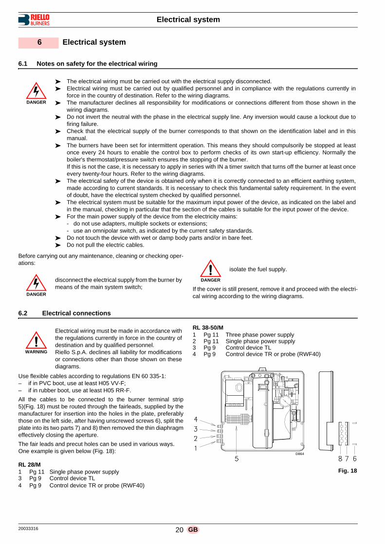
All the cables to be connected to the burner terminal strip5)(Fig. 18) must be routed through the fairleads, supplied by themanufacturer for insertion into the holes in the plate, preferablythose on the left side, after having unscrewed screws 6), split theplate into its two parts 7) and 8) then removed the thin diaphragmeffectively closing the aperture.
The fair leads and precut holes can be used in various ways.One example is given below (Fig. 18):
RL 28/M 1 Pg 11 Single phase power supply3 Pg 9 Control device TL4 Pg 9 Control device TR or probe (RWF40)
RL 38-50/M 1 Pg 11 Three phase power supply2 Pg 11 Single phase power supply3 Pg 9 Control device TL4 Pg 9 Control device TR or probe (RWF40)
6 Electrical system
DANGER
The electrical wiring must be carried out with the electrical supply disconnected. Electrical wiring must be carried out by qualified personnel and in compliance with the regulations currently in
force in the country of destination. Refer to the wiring diagrams. The manufacturer declines all responsibility for modifications or connections different from those shown in the
wiring diagrams. Do not invert the neutral with the phase in the electrical supply line. Any inversion would cause a lockout due to
firing failure. Check that the electrical supply of the burner corresponds to that shown on the identification label and in this
manual. The burners have been set for intermittent operation. This means they should compulsorily be stopped at least
once every 24 hours to enable the control box to perform checks of its own start-up efficiency. Normally theboiler's thermostat/pressure switch ensures the stopping of the burner.If this is not the case, it is necessary to apply in series with IN a timer switch that turns off the burner at least onceevery twenty-four hours. Refer to the wiring diagrams.
The electrical safety of the device is obtained only when it is correctly connected to an efficient earthing system,made according to current standards. It is necessary to check this fundamental safety requirement. In the eventof doubt, have the electrical system checked by qualified personnel.
The electrical system must be suitable for the maximum input power of the device, as indicated on the label andin the manual, checking in particular that the section of the cables is suitable for the input power of the device.
For the main power supply of the device from the electricity mains:- do not use adapters, multiple sockets or extensions;- use an omnipolar switch, as indicated by the current safety standards.
Do not touch the device with wet or damp body parts and/or in bare feet. Do not pull the electric cables.
DANGER
disconnect the electrical supply from the burner bymeans of the main system switch;
DANGER
isolate the fuel supply.
WARNING
Electrical wiring must be made in accordance withthe regulations currently in force in the country ofdestination and by qualified personnel.Riello S.p.A. declines all liability for modificationsor connections other than those shown on thesediagrams.
Fig. 18
D864
21 20033316GB
Electrical system
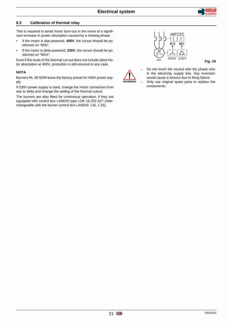
6.3 Calibration of thermal relay
This is required to avoid motor burn-out in the event of a signifi-cant increase in power absorption caused by a missing phase.
• If the motor is star-powered, 400V, the cursor should be po-sitioned on "MIN".
• If the motor is delta-powered, 230V, the cursor should be po-sitioned on "MAX".
Even if the scale of the thermal cut-out does not include rated mo-tor absorption at 400V, protection is still ensured in any case.
NOTA
Burners RL 38-50/M leave the factory preset for 400V power sup-ply.
If 230V power supply is used, change the motor connection fromstar to delta and change the setting of the thermal cutout.
The burners are also fitted for continuous operation, if they areequipped with control box LANDIS type LOK 16.250 A27 (inter-changeable with the burner control box LANDIS LAL 1.25).
WARNING
– Do not invert the neutral with the phase wirein the electricity supply line. Any inversionwould cause a lockout due to firing failure.
– Only use original spare parts to replace thecomponents.
D867 Fig. 19

20033316 22 GB
Start-up, calibration and operation of the burner
7.1 Notes on safety for the first start-up
7.2 Burner firing
Close load controls and set switch 1)(Fig. 20) to “MAN”.
After burner firing a complete burner adjustment should be per-formed.
7.3 Burner calibration
The optimum calibration of the burner requires an analysis of theflue gases at the boiler outlet.
Adjust successively:– Combustion head – Servomotor – MAX burner output– MIN burner output– Intermediate outputs between MAX and MIN output
7.3.1 Combustion head setting
The setting of the combustion head depends exclusively on themaximum burner delivery at which it will be operating.
Turn screw 4)(Fig. 21) until the notch shown in diagram (Fig. 22)is level with the front surface of flange 5)(Fig. 21).
Example:
RL 50/M, maximum light oil delivery = 32 kg/h.Diagram (Fig. 22) indicates that for a delivery of 32 kg/h the burn-er requires the combustion head to be set to approx. three notch-es, as shown in Fig. 21.
7.3.2 Servomotor
The servomotor (Fig. 23) provides simultaneous adjustment ofthe air gate valve 11)(Fig. 24 at page 23) and the pressure regu-lator 9) by means of a double variable profile cam, 4) and 7).
The servomotor rotates through 90° in 24 seconds.
Do not alter the factory setting for the 4 cams; simply check thatthey are set as indicated below:
Cam I: 90°Limits rotation toward maximum position.
Cam II: 0°Limits rotation toward the minimum position. When theburner is shut down the air gate valve must be closed:0°.
Cam III: 15°Adjusts the ignition position and the MIN output.
Cam IV: not utilized.
7 Start-up, calibration and operation of the burner
WARNING
The first start-up of the burner must be carried outby qualified personnel, as indicated in this manualand in compliance with the standards and regula-tions of the laws in force. WARNING
Check the correct working of the adjustment, com-mand and safety devices.
Fig. 20
1 2
D791
Fig. 21D462
Fig. 22
Notches
Max light oil delivery - kg/h
Fig. 23D790

23 20033316GB
Start-up, calibration and operation of the burner
7.3.3 MAX power
Max output of the burner must be set within the firing rate rangeshown on page 11.
In the above instructions we left the burner running in MIN outputoperation. Now press button 2)(Fig. 20 at page 22) “+” until ser-vomotor arrives at 90°.
Adjusting the nozzle flow rate
The nozzle flow rate varies according to the fuel pressure on thenozzle return. Diagram (Fig. 25) indicates this relationship for type A3 Bergonzonozzles with pump delivery pressure of 20 bar.
NOTEWith a pump delivery pressure of 20 bars, the pressure on thenozzle return must not exceed 17 bar.The pressure difference between pump delivery and nozzle re-turn must be at least 3 bars. With smaller pressure differences,the pressure on the nozzle return can be unstable.To fix the maximum nozzle flow rate, vary the final profile on theupper cam 7)(Fig. 24) via the screws 8).The nozzle return pressure value is indicated by the pressuregauge 10).
Key (Fig. 24)1 Servomotor2 Cams 4) - 7) engaged / disengaged 3 Servomotor cams cover4 Cam for controlling air gate valve5 Cam 4) adjustable screws6 Opening for access to screws 5)7 Cam for controlling pressure regulator8 Cam 7) adjustable screws9 Pressure regulator10 Gauge for pressure on nozzle return11 Air gate valve12 Index
Key (Fig. 25)Horizontal axis: kg/h, nozzle flow rateVertical axis: bar, nozzle return pressure
Adjusting air delivery
Two shutters 1) and 2)(Fig. 26) are provided to adjust the air.These shutters are factory set to maximum opening.
Firstly adjust shutter 2) which must be closed gradually until opti-mum combustion is obtained.
If total closure of shutter 2) is not sufficient, also close shutter 1)(secondly) as follows: vary the final profile of the lower cam 4)(Fig. 24) via the
screws 5) inside the opening 6).
If the burner is operated at maximum power, the fan air may notbe sufficient even with both shutters 1) and 2) fully open.
In this case, remove shutter 2) and adjust the air using shutter 1)only as described above.
Cams 7)-4)(Fig. 24):– tighten screws 8)-5) to increase air delivery – unscrew screws 8)-5) to reduce air delivery
Fig. 24D869
Fig. 25
D870
Fig. 26
D871

20033316 24 GB
Start-up, calibration and operation of the burner
7.3.4 MIN power
The MIN power must be chosen from within the working rangegiven on page 11.
Press the “-” button 2)(Fig. 20 at page 22) and keep it presseduntil the servomotor has reached 15° (factory setting).
Nozzle flow rate adjustment
The nozzle flow rate is given in diagram (Fig. 25 at page 23) cor-responding to the pressure on the nozzle return read on the pres-sure gauge 10)(Fig. 24 at page 23).
To vary the nozzle minimum flow rate, modify the initial profile ofthe upper cam 7)(Fig. 24 at page 23) via the screws 8).
Adjusting air delivery
Modify the initial profile of the lower cam 4)(Fig. 24 at page 23)via the screws 5) inside the opening 6).
If possible, do not rotate the first screw as this is the one that pro-vides for total closure of the air shutter.
7.3.5 Intermediate power
Air/oil flow rate adjustment
Slightly press the "+" button 2)(Fig. 20 at page 22) so that a newscrew 5)(Fig. 24 at page 23) appears inside the opening 6).
Adjust screw 8) which varies the profile of the upper cam 7) andthe corresponding screw 5) which controls the lower cam 4) untilyou obtain optimum combustion.
Proceed in the same way with the next screws except for the lastone, previously adjusted to obtain maximum power.
Ensure that variation of the cams profile is gradual.
Turn the burner off via switch 1)(Fig. 20 at page 22), OFF posi-tion, release the cam with variable profile by setting the servomo-tor notch 2)(Fig. 24 at page 23) to the vertical position and checkthat the movement is smooth by manually rotating the cam back-wards and forwards several times.
NOTE
Cams I - II - IV of the servomotor do not require adjustment. Only cam III may need adjusting. In this case, remove the cover1)(Fig. 27), which clicks in and out, take the key 2) out and insertit in the notch on cam III.The servomotor follows the adjustment of cam III only when thecam angle is reduced. If you need to increase the cam angle (15..16..17°..), first in-crease the servomotor angle via the "+" button, then increase theangle of cam III and finally reset the servomotor to the MIN powerposition via the “-” button.
7.4 Oil pressure switch
The oil pressure switch 14)(Fig. 29 at page 25) is factory set to 3bar.
If the gas oil pressure reaches this value in the return piping, thepressure switch stops the burner.
Burner starts again automatically if the pressure goes down un-der 3 bar after burner shut down.
If a loope circuit (page 17) with Px pressure feeds the burner, thepressure switch should be adjusted to Px + 3 bar.
Fig. 27D793

25 20033316GB
Start-up, calibration and operation of the burner
7.5 Burner operation
7.5.1 Burner starting 0 s: Control device TL closes, the motor starts.
The pump 3)(Fig. 29) sucks the fuel from the tank through the piping 1) and the filter 2) and pumps it under pressure to delivery. The piston 4) rises and the fuel returns to the tank through the piping 5) - 7). The screw 6) closes the by-pass heading towards suc-tion and the de-energized solenoid valves 8) - 15) - 16) close the passage to the nozzle.
5 s: Servomotor starts: 90° rotation to right, until contact is made on cam I)(Fig. 23 at page 22). The air gate valve is positioned on MAX. output.
29 s: Pre-purge stage with air delivery at MAX. output. 51 s: Servomotor rotates to left until contact is made on cam
III)(Fig. 23 at page 22).71 s: Air gate valve and pressure regulator are positioned on
MIN output.72.5 s: Ignition electrode strikes a spark.75 s: Solenoid valves 8) - 15) - 16) open; the fuel passes
through the piping 9) and filter 10), finally it enters the nozzle.A part of the fuel is then sprayed out through the nozzle, igniting when it comes into contact with the spark: flame at a low output level, point A; the rest of the fuel passes through piping 11) at the pressure adjusted by the regu-lator 12), then, through piping 7), it goes back into the tank.
80 s: The spark goes out.90 s: The starting cycle ends.
7.5.2 Steady state operation
Burner without output regulator RWF40At the end of the starting cycle, the servo-motor control thenpasses to load control TR for boiler pressure or temperature,point B.
• If the temperature or pressure is low (and the TR load controlis consequently closed), the burner progressively increasesoutput up to MAX (section B-C).
• If subsequently the temperature or pressure increases untilTR opens, the burner progressively decreases output downto MIN (section D-E). And so on.
• The burner locks out when demand for heat is less than theheat supplied by the burner in the MIN output (section F-G).Load control TL opens. The servomotor returns to the 0° an-gle limited by contact with cam II)(Fig. 23 at page 22).The gate valve closes completely to reduce thermal disper-sion to a minimum.
Every time output is changed, the servomotor automatically mod-ifies gas oil delivery (pressure regulator) and air delivery (fan gatevalve).
Burner with output regulator RWF40 See the handbook enclosed with the regulator. 7.5.3 Firing failure
If the burner does not fire, it goes into lock-out within 5 s of theopening of the light oil valve.
7.5.4 Firing failure
If the flame should go out for accidental reasons during operation,the burner will lock out in 1 s.
Fig. 28D872
Fig. 29
D873

20033316 26 GB
Start-up, calibration and operation of the burner
7.6 Final checks
Obscure the photocell and switch off the control devices:the burner should start and then lock-out about 5 s afterstarting.
Illuminate the photocell and switch off the control devices:burner should go into lock-out.
Obscure the photocell while the burner is operating:flame should go out and burner lock out within 1 s.
Switch on control device TL followed by control device TSwhile the burner is operating:the burner should stop.

27 20033316GB
Maintenance
8.1 Notes on safety for the maintenance
The periodic maintenance is essential for the good operation,safety, yield and duration of the burner.
It allows you to reduce consumption and polluting emissions andto keep the product in a reliable state over time.
Before carrying out any maintenance, cleaning or checking oper-ations:
8.2 Maintenance programme
8.2.1 Maintenance frequency
The combustion system should be checked at least once a yearby a representative of the manufacturer or another specialisedtechnician.
8.2.2 Checking and cleaning
Combustion
The optimum calibration of the burner requires an analysis of theflue gases. Significant differences with respect to the previous measure-ments indicate the points where more care should be exercisedduring maintenance.
Combustion head
Check to make sure that all the parts of the combustion head arein good condition, positioned correctly, free of all impurities, andthat no deformation has been caused by operation at high tem-peratures.
Photocell
Clean the glass cover from any dust that may have accumulated.Photocell 1)(Fig. 30) is held in position by a pressure fit and cantherefore be removed by pulling it outward forcefully.
Burner
Check for excess wear or loose screws. Also make sure that thescrews securing the electrical leads in the burner connections arefully tightened.
Clean the outside of the burner.
Servomotor
Disengage servomotor by turning slot 2)(Fig. 24 at page 23)through 90° and turn it backward and forward by hand to makesure it is free moving.
FanCheck to make sure that no dust has accumulated inside the fanor on its blades, as this condition will cause a reduction in the airflow rate and provoke polluting combustion.
Boiler
Clean the boiler as indicated in its accompanying instructions inorder to maintain all the original combustion characteristics in-tact, especially the flue gas temperature and combustion cham-ber pressure.
Flame inspection window
Clean the glass (Fig. 31).
Filters
Check the filtering baskets on line and at nozzle present in thesystem. Clean or replace if necessary. If rust or other impurities are observed inside the pump, use a
8 Maintenance
DANGER
The maintenance interventions and the calibrationof the burner must only be carried out by qualified,authorised personnel, in accordance with the con-tents of this manual and in compliance with thestandards and regulations of current laws.
DANGER
Disconnect the electrical supply from the burnerby means of the main system switch.
DANGER
Close the fuel interception tap.
Fig. 30D874
Fig. 31D484
20033316 28 GB
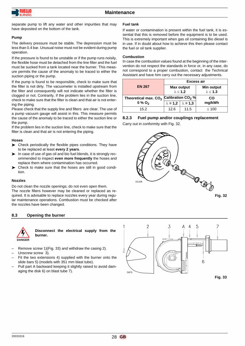
Maintenance
separate pump to lift any water and other impurities that mayhave deposited on the bottom of the tank.
Pump
The delivery pressure must be stable. The depression must beless than 0.4 bar. Unusual noise must not be evident during pumpoperation.
If the pressure is found to be unstable or if the pump runs noisily,the flexible hose must be detached from the line filter and the fuelmust be sucked from a tank located near the burner. This meas-ure permits the cause of the anomaly to be traced to either thesuction piping or the pump.
If the pump is found to be responsible, check to make sure thatthe filter is not dirty. The vacuometer is installed upstream fromthe filter and consequently will not indicate whether the filter isclogged or not. Contrarily, if the problem lies in the suction line,check to make sure that the filter is clean and that air is not enter-ing the piping.Please check that the supply line and filters are clear. The use ofa pump vacuum gauge will assist in this. This measure permitsthe cause of the anomaly to be traced to either the suction line orthe pump.If the problem lies in the suction line, check to make sure that thefilter is clean and that air is not entering the piping.
Hoses Check periodically the flexible pipes conditions. They have
to be replaced at least every 2 years. In case of use of gas oil and bio fuel blends, it is strongly rec-
ommended to inspect even more frequently the hoses andreplace them where contamination has occurred.
Check to make sure that the hoses are still in good condi-tion.
Nozzles
Do not clean the nozzle openings; do not even open them.The nozzle filters however may be cleaned or replaced as re-quired. It is advisable to replace nozzles every year during regu-lar maintenance operations. Combustion must be checked afterthe nozzles have been changed.
Fuel tank
If water or contamination is present within the fuel tank, it is es-sential that this is removed before the equipment is to be used.This is extremely important when gas oil containing Bio diesel isin use. If in doubt about how to achieve this then please contactthe fuel or oil tank supplier.
CombustionIn case the combustion values found at the beginning of the inter-vention do not respect the standards in force or, in any case, donot correspond to a proper combustion, contact the TechnicalAssistant and have him carry out the necessary adjustments.
8.2.3 Fuel pump and/or couplings replacement
Carry out in conformity with Fig. 32.
8.3 Opening the burner
– Remove screw 1)(Fig. 33) and withdraw the casing 2).– Unscrew screw 3).– Fit the two extensions 4) supplied with the burner onto the
slide bars 5) (models with 351 mm blast tube).– Pull part A backward keeping it slightly raised to avoid dam-
aging the disk 6) on blast tube 7).
EN 267Excess air
Max output 1.2
Min output 1.3
Theoretical max. CO20 % O2
Calibration CO2 % COmg/kWh = 1,2 = 1,3
15.2 12.6 11.5 100
Fig. 32
D1108
DANGER
Disconnect the electrical supply from theburner.
Fig. 33
D875

29 20033316GB
Faults - Possible causes - Solutions
Find a list of faults, causes and possible solutions for a set of failures that may occur and result in irregular burner operation or nofunctioning at all.
If a burner malfunction is detected, first of all:• check that the electrical wiring is adequately connected;• check whether fuel is delivered;• check that every adjustment parameter is adequately set.
9 Faults - Possible causes - Solutions
SYMBOL (1) FAULT PROBABLE CAUSE SUGGESTED REMEDY
The burner does not start A limit or safety control device is open Adjust or replace
Control box lock-out Reset control box
Oil pressure switch intervenes Adjust pressure switch or eliminate overpressure
Motor protection tripped (RL 38-50/M) Reset thermal cut-out
No electrical power supply Close all switches - Check connections
Control box fuse blown Replace (2)
Contact II of servomotor does not operate, control box terminals 11 - 8
Adjust cam II or replace servo-motor
Pump is jammed Replace
Defective capacitor (RL 28/M) Replace
Defective motor command control device
(RL 38-50/M)Replace
Defective control box Replace
Defective electrical motor Replace
The burner does not start and
a function lock-out occurs
Flame simulation Replace control box
Photocell short-circuit Replace photocell
Missing phase (RL 38-50/M) thermal cut-out tripsReset thermal cut-out when third phase is re-con-
nected
The burner starts but stops at maximum air damper setting
Contact I of servomotor does not operate, control box terminals 9-8
Adjust cam I or replace servomotor
The burner starts and then
goes into lock-outFault in flame detection circuit Replace control box
The burner remains in pre-purging phase
Contact III of servomotor does not operate, con-trol box terminals 10-8
Adjust cam III or replace servomotor
After pre-purge and the safety
time, the burner goes to lock-out and the flame does not
appear
No fuel in tank; water on tank bottom Top up fuel level or suck up water
Inappropriate head and air damper adjustments Adjust
Light oil solenoid valves fail to open Check connections; replace coil
Nozzle clogged, dirty, or deformed Replace
Dirty or poorly adjusted firing electrodes Adjust or clean
Grounded electrode due to broken insulation Replace
High voltage cable defective or grounded Replace
High voltage cable deformed by high temperature Replace and protect
Ignition transformer defective Replace
Erroneous electrical connections of valves or
transformerCheck
Defective control box Replace
Pump unprimed Prime pump and see "Pump unprimes” (54-55)
Pump/motor coupling broken Replace
Pump suction line connected to return line Correct connection
Valves up-line from pump closed Open
Filters dirty: line - pump - nozzle Clean
Incorrect motor rotation direction Change motor electrical connections
The flame ignites normally but
the burner locks out when the safety time has elapsed
Defective photocell or control box Replace photocell or control box
Dirty photocell Clean
Firing with pulsations or flame
detachment, delayed firing
Poorly adjusted head Adjust
Poorly adjusted or dirty firing electrodes Adjust
Poorly adjusted fan air gate: too much air Adjust
Nozzle unsuited for burner or boiler See Nozzle Table
Defective nozzle Replace
Inappropriate pump pressure Adjust
The burner does not pass to
2nd stage
Control device TR does not close Adjust or replace
Defective control box Replace
1

20033316 30 GB
Faults - Possible causes - Solutions
(1) When the burner does not fire or comes to a halt following afault, the symbol which appears on control box 23)(Fig. 4 atpage 12) indicates the type of problem.
(2) The fuse is located in the rear part of the control box23)(Fig. 4 at page 12). A pull-out fuse is also available as aspare part which can be fitted after breaking the tang on thepanel which holds it in place.
Uneven fuel supply Check if cause is in pump or fuel supply system Feed burner from tank located near burner
Internally rusted pump Water in tank Suck water from tank bottom with separate pump
Noisy pump, unstable pres-
sure
Air has entered the suction line Tighten connectors
- Depression value too high (higher than 35 cm Hg):
Tank/burner height difference too great Feed burner with loop circuit
Piping diameter too small Increase
Suction filters clogged Clean
Suction valves closed Open
Paraffin solidified due to low temperature Add additive to light oil
Pump unprimes after pro-longed pause
Return pipe not immersed in fuel Bring to same height as suction pipe
Air enters suction piping Tighten connectors
Pump leaks gas oil Leakage from sealing organ Replace pump
Smoke in flame - dark Bach-arach
- yellow Bacharach
Not enough air Adjust head and fan gate
Nozzle worn or dirty Replace
Nozzle filter clogged Clean or replace
Erroneous pump pressure Adjust
Flame stability disk dirty, loose, or deformed Clean, tighten in place, or replace
Boiler room air vents insufficient Increase
Too much air Adjust head and fan gate
Dirty combustion head Nozzle or filter dirty Replace
Unsuitable nozzle delivery or angle See recommended nozzles
Loose nozzle Tighten
Impurities on flame stability disk Clean
Erroneous head adjustment or not enough air Adjust, open air damper
Blast tube length unsuited to boiler Contact boiler manufacturer
During operation, the burner
stops in lock outDirty or defective photocell Clean or replace
SYMBOL (1) FAULT PROBABLE CAUSE SUGGESTED REMEDY
I

31 20033316GB
Appendix - Accessories (optional)
OUTPUT POWER REGULATOR KIT RWF 40
With the modulating operation, the burner continually adapts thepower to the request for heat, ensuring great stability for the pa-rameter controlled: temperature or pressure.
Two components should be ordered: • the output regulator to install on the burner• the probe to install on the heat generator
POTENTIOMETER KIT
Depending on the servomotor fi tted to the burner, a three-polepotentiometer (1000 ) can be installed to check the position ofthe servomotor.
EXTENDED HEAD KIT
“Standard head” burners can be transformed into “extendedhead” versions, by using the special kit. The kits available for thevarious burners, giving the original and the extended lengths, arelisted below.
DEGASSING UNIT
It may occur that a certain amount of air is contained in the fuelsucked up by the pump.This air may originate from the fuel itself as a consequence of de-pressurisation or air leaking past imperfect seals. In double-pipe systems, the air returns to the tank from the returnpipe; in single-pipe systems, the air remains in circulation causingpressure variations in the pump and burner malfunctions.For this reason, we advise installing a degassing unit near theburner in single-pipe installations. Degassing units are provided in two versions:
SPACER KIT
If burner head penetration into the combustion chamber needsreducing, varying thickness spacers are available, as given in thefollowing table.
HEAD KIT FOR REVERSE FLAME CHAMBER
In certain cases, the use of the burner on reverse flame boilerscan be improved by using an additional cylinder.
CONNECTION FLANGE KIT
A kit is available for use where the burner opening on the boileris of excessive diameter.
SOUND PROOFING BOX
If noise emission needs reducing even further, sound-proofingboxes is available.
A Appendix - Accessories (optional)
Parameter to control Probe Output power regulator
Range Type Code Type Code
Temperature - 100...+ 500°C PT 100 3010110
RWF40 3010212Pressure
0...2.5 bar0...16 bar
Probe with output4...20 A
30102133010214
Burner Code
RL 28-38-50/M 3010109
Burner Code
RL 28/M 3010120
RL 38/M 3010121
RL 50/M 3010122
Degassing unit characteristics
Burner output 80 kg/h max
Fuel pressure 0.7 bar max
Ambient temperature 40 °C max
Fuel temperature 40 °C max
Attachment connectors(without filter)
FF G 1/4 tank sideFM G 3/8 conic burner side
Attachment connectors(with filter)
FF G 3/8 tank sideFM G3/8 conic burner side
Burner Code
RL 28-38-50/M 3010095
BurnerStandard
head (mm)Extended
head (mm)Code
RL 28-38/M 319 429 3010178
RL 50/M 319 429 3010179
Burner Code
RL 28-38-50/M 3010138
Burner Box type
Average noise
reduction [dB(A)]
Code
RL 28-38-50/M C1/3 10 3010403

20033316 32 GB
Appendix - Electrical panel layout
ELECTRICAL EQUIPMENT FACTORY-SET
B Appendix - Electrical panel layout
RL 28/M
D862
Fig. 1
RL 38-50/M
Fig. 2D863
WARNING
Models RL 38-50/M leave the factory preset for 400V power supply.
If 230V power supply is used, change the motor connection from star to delta and change the setting of the thermalcut-out as well.
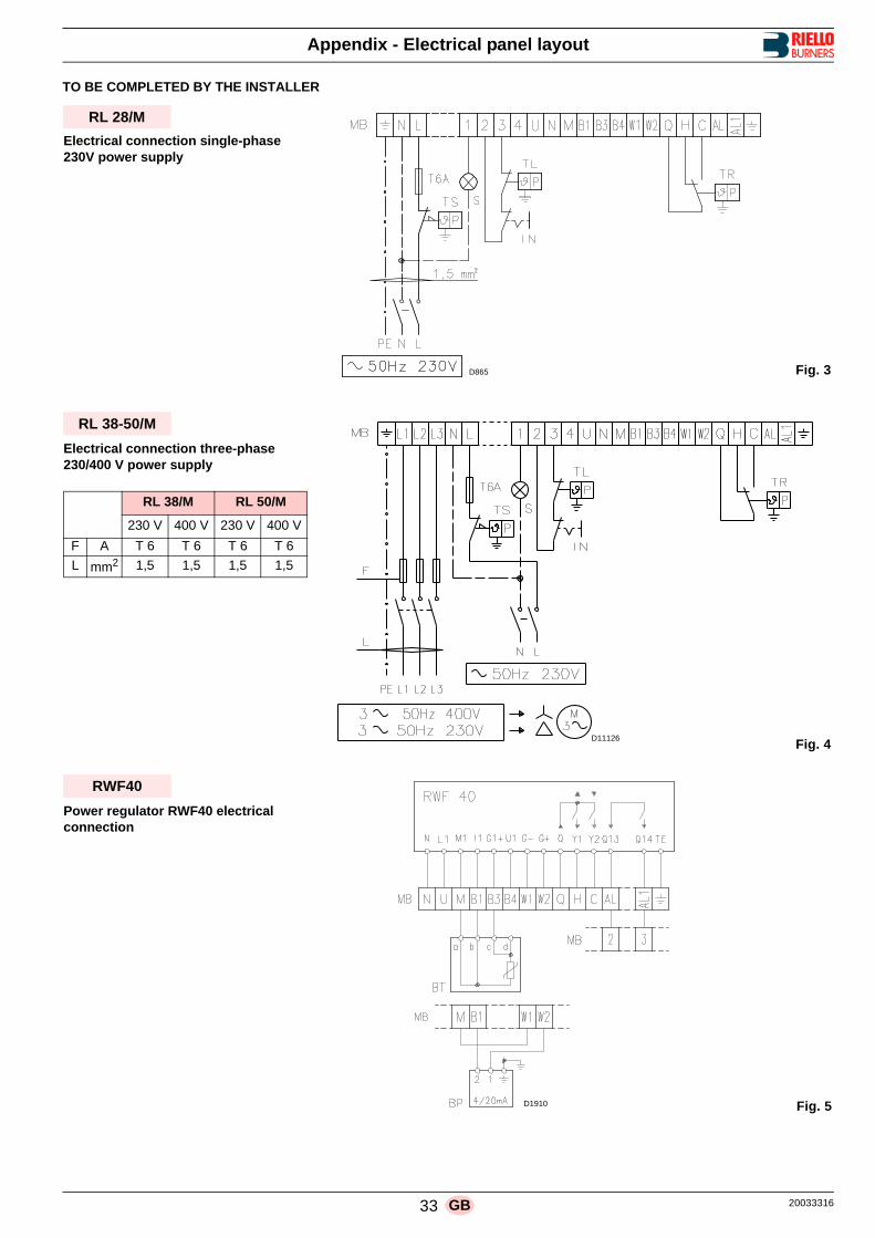
33 20033316GB
Appendix - Electrical panel layout
TO BE COMPLETED BY THE INSTALLER
D865
RL 28/M
Electrical connection single-phase230V power supply
Fig. 3
Fig. 4
RL 38-50/M
RL 38/M RL 50/M
230 V 400 V 230 V 400 V
F A T 6 T 6 T 6 T 6
L mm2 1,5 1,5 1,5 1,5
D11126
Electrical connection three-phase230/400 V power supply
Fig. 5
RWF40
Power regulator RWF40 electrical connection
D1910

20033316 34 GB
Appendix - Electrical panel layout
Key to layout a - d rosso/rot/red/rougeb - c bianco/weiss/white/blancBP Pressure probeBT Temperature probeC CapacitorCMV Motor contactorLAL 1.25 Control boxF1 Protection against radio interferenceFR PhotocellIN Manual burner stop switchMB Terminal stripMV Fan motorPO Oil pressure switchRT Thermal cut-outS Remote lock-out signalS1 Switch for following operations :
MAN = manualAUT = automaticOFF
S2 Button for :- = power reduction+ = power increase
SM ServomotorTA Ignition transformerTB Burner ground (earth) connectionTL Limit control device system:
this shuts down the burner when the boiler tempera-ture or pressure exceeds the setpoint value.
TR High-low mode control device system: controls operating stages 1 and 2. The TR load control is not required when the regulatorRWF40 is connected as its function is performed bythe regulator RWF40 itself.
TS Safety control device system: this operates when TL is faulty
VM Delivery pump valveVS Delivery pump valve (safety valve)VU Valve on nozzle return


Subject to modifications
RIELLO S.p.A.
I-37045 Legnago (VR)
Tel.: +39.0442.630111
http:// www.rielloburners.com