
Turbomachinery Design and Theory - sv.20file.orgsv.20file.org/up1/1042_4.pdf · turbine with...
51
3 Hydraulic Turbines 3.1 INTRODUCTION In a hydraulic turbine, water is used as the source of energy. Water or hydraulic turbines convert kinetic and potential energies of the water into mechanical power. The main types of turbines are (1) impulse and (2) reaction turbines. The predominant type of impulse machine is the Pelton wheel, which is suitable for a range of heads of about 150–2,000 m. The reaction turbine is further subdivided into the Francis type, which is characterized by a radial flow impeller, and the Kaplan or propeller type, which is an axial-flow machine. In the sections that follow, each type of hydraulic turbine will be studied separately in terms of the velocity triangles, efficiencies, reaction, and method of operation. 3.2 PELTON WHEEL An American Engineer Lester A. Pelton discovered this (Fig. 3.1) turbine in 1880. It operates under very high heads (up to 1800 m.) and requires comparatively less quantity of water. It is a pure impulse turbine in which a jet of fluid delivered is by the nozzle at a high velocity on the buckets. These buckets are fixed on the periphery of a circular wheel (also known as runner), which is generally mounted on a horizontal shaft. The primary feature of the impulse Copyright 2003 by Marcel Dekker, Inc. All Rights Reserved
Transcript of Turbomachinery Design and Theory - sv.20file.orgsv.20file.org/up1/1042_4.pdf · turbine with...
3
Hydraulic Turbines
3.1 INTRODUCTION
In a hydraulic turbine, water is used as the source of energy. Water or hydraulic
turbines convert kinetic and potential energies of the water into mechanical
power. The main types of turbines are (1) impulse and (2) reaction turbines. The
predominant type of impulse machine is the Pelton wheel, which is suitable for a
range of heads of about 150–2,000m. The reaction turbine is further subdivided
into the Francis type, which is characterized by a radial flow impeller, and
the Kaplan or propeller type, which is an axial-flow machine. In the sections that
follow, each type of hydraulic turbine will be studied separately in terms of the
velocity triangles, efficiencies, reaction, and method of operation.
3.2 PELTON WHEEL
An American Engineer Lester A. Pelton discovered this (Fig. 3.1) turbine in
1880. It operates under very high heads (up to 1800m.) and requires
comparatively less quantity of water. It is a pure impulse turbine in which a jet of
fluid delivered is by the nozzle at a high velocity on the buckets. These buckets
are fixed on the periphery of a circular wheel (also known as runner), which is
generally mounted on a horizontal shaft. The primary feature of the impulse
Copyright 2003 by Marcel Dekker, Inc. All Rights Reserved
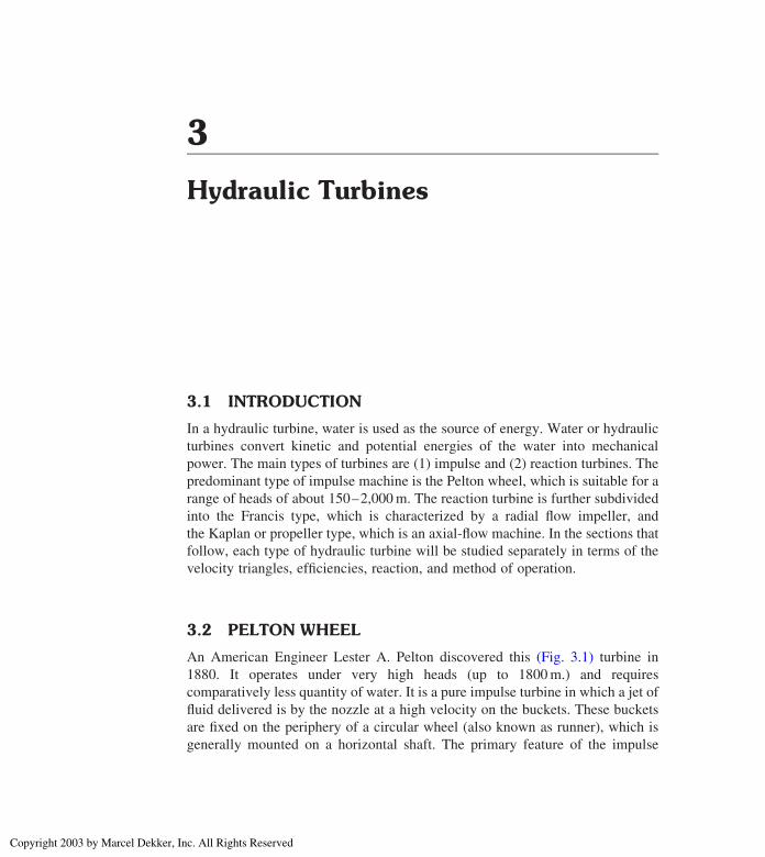
turbine with respect to fluid mechanics is the power production as the jet is
deflected by the moving vane(s).
The impact of water on the buckets causes the runner to rotate and thus
develops mechanical energy. The buckets deflect the jet through an angle of
about 160 and 1658 in the same plane as the jet. After doing work on the buckets
water is discharged in the tailrace, and the whole energy transfer from nozzle
outlet to tailrace takes place at constant pressure.
The buckets are so shaped that water enters tangentially in the middle and
discharges backward and flows again tangentially in both the directions to avoid
thrust on the wheel. The casing of a Pelton wheel does not perform any hydraulic
function. But it is necessary to safeguard the runner against accident and also to
prevent the splashing water and lead the water to the tailrace.
3.3 VELOCITY TRIANGLES
The velocity diagrams for the Pelton wheel are shown in Fig. 3.2.
Since the angle of entry of the jet is nearly zero, the inlet velocity triangle is
a straight line, as shown in Fig. 3.2. If the bucket is brought to rest, then the
relative fluid velocity, V1, is given by
V1 ¼ jet velocity2 bucket speed
¼ C1 2 U1
The angle turned through by the jet in the horizontal plane during its passage over
the bucket surface is a and the relative velocity at exit is V2. The absolute
Figure 3.1 Single-jet, horizontal shaft Pelton turbine.
Chapter 392
Copyright 2003 by Marcel Dekker, Inc. All Rights Reserved

velocity, C2, at exit can be obtained by adding bucket speed vector U2 and
relative velocity, V2, at exit.
Now using Euler’s turbine Eq. (1.78)
W ¼ U1CW1 2 U2CW2
Since in this case CW2 is in the negative x direction,
W ¼ U ðU þ V1Þ þ V1 cosð1802 aÞ2 U½ �f gNeglecting loss due to friction across the bucket surface, that is, V1 ¼ V2,
then
W ¼ UðV1 2 V1 cosaÞTherefore
E ¼ UðC1 2 UÞð12 cosaÞ/g ð3:1Þthe units of E being Watts per Newton per second weight of flow.
Eq. (3.1) can be optimized by differentiating with respect to U, and
equating it to zero.
Therefore
dE
dU¼ ð12 cosaÞðC1 2 2UÞ/g ¼ 0
Then
C1 ¼ 2U or U ¼ C1/2 ð3:2Þ
Figure 3.2 Velocity triangles for a Pelton wheel.
Hydraulic Turbines 93
Copyright 2003 by Marcel Dekker, Inc. All Rights Reserved

Substituting Eq. (3.2) into Eq. (3.1) we get
Emax ¼ C21ð12 cosaÞ/4g
In practice, surface friction is always present and V1 – V2, then Eq. (3.1)
becomes
E ¼ UðC1 2 UÞð12 k cosaÞ/g ð3:3Þwhere k ¼ V2
V1
Introducing hydraulic efficiency as
hh¼ Energy Transferred
Energy Available in jet
i:e: hh¼ E
ðC21/2gÞ
ð3:4Þ
if a ¼ 1808, the maximum hydraulic efficiency is 100%. In practice, deflection
angle is in the order of 160–1658.
3.4 PELTON WHEEL (LOSSES AND EFFICIENCIES)
Head losses occur in the pipelines conveying the water to the nozzle due to
friction and bend. Losses also occur in the nozzle and are expressed by the
velocity coefficient, Cv.
The jet efficiency (hj) takes care of losses in the nozzle and the mechanical
efficiency (hm) is meant for the bearing friction and windage losses. The overall
efficiency (ho) for large Pelton turbine is about 85–90%. Following efficiency is
usually used for Pelton wheel.
Pipeline transmission efficiency ¼ Energy at end of the pipe
Energy available at reservoir
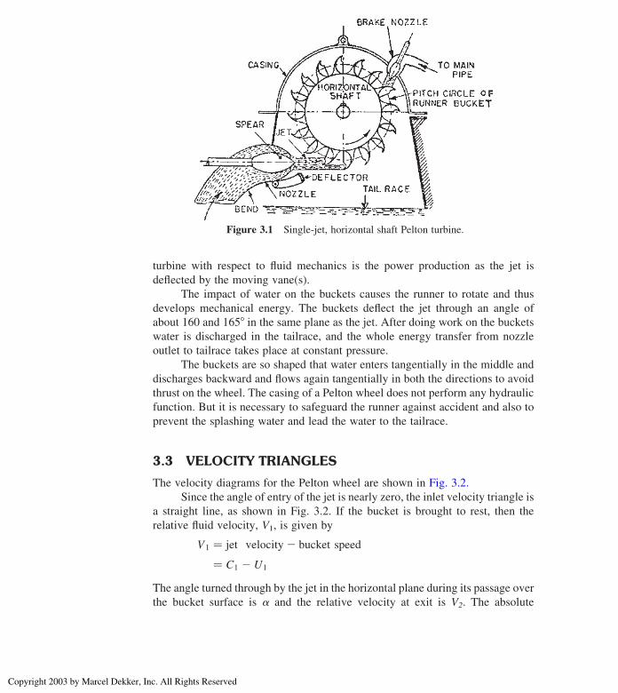
Figure 3.3 shows the total headline, where the water supply is from a
reservoir at a head H1 above the nozzle. The frictional head loss, hf, is the loss as
the water flows through the pressure tunnel and penstock up to entry to the nozzle.
Then the transmission efficiency is
htrans ¼ ðH1 2 hfÞ/H1 ¼ H/H1 ð3:5ÞThe nozzle efficiency or jet efficiency is
hj ¼Energy at nozzle outlet
Energy at nozzle inlet¼ C2
1/2gH ð3:6Þ
Chapter 394
Copyright 2003 by Marcel Dekker, Inc. All Rights Reserved
Nozzle velocity coefficient
Cv ¼ Actual jet velocity
Theoretical jet velocity¼ C1=
ffiffiffiffiffiffiffiffiffi2gH
p
Therefore the nozzle efficiency becomes
hj ¼ C21=2gH ¼ C2
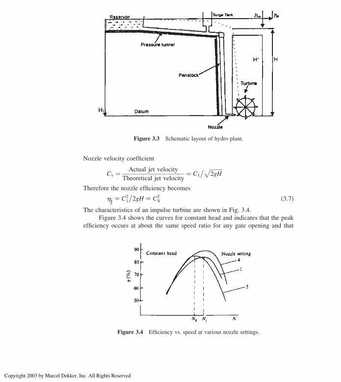
v ð3:7ÞThe characteristics of an impulse turbine are shown in Fig. 3.4.
Figure 3.4 shows the curves for constant head and indicates that the peak
efficiency occurs at about the same speed ratio for any gate opening and that
Figure 3.3 Schematic layout of hydro plant.
Figure 3.4 Efficiency vs. speed at various nozzle settings.
Hydraulic Turbines 95
Copyright 2003 by Marcel Dekker, Inc. All Rights Reserved

the peak values of efficiency do not vary much. This happens as the nozzle
velocity remaining constant in magnitude and direction as the flow rate changes,
gives an optimum value of U/C1 at a fixed speed. Due to losses, such as windage,
mechanical, and friction cause the small variation. Fig. 3.5 shows the curves for
power vs. speed. Fixed speed condition is important because generators are
usually run at constant speed.
Illustrative Example 3.1: A generator is to be driven by a Pelton wheel
with a head of 220m and discharge rate of 145 L/s. The mean peripheral velocity
of wheel is 14m/s. If the outlet tip angle of the bucket is 1608, find out the powerdeveloped.
Solution:
Dischargerate;Q ¼ 145L/s
Head;H ¼ 220m
U1 ¼ U2 ¼ 14m/s
b2 ¼ 1802 1608 ¼ 208
Refer to Fig. 3.6
Using Euler’s equation, work done per weight mass of water per sec.
¼ ðCw1U1 2 Cw2U2ÞBut for Pelton wheel Cw2 is negative
Figure 3.5 Power vs. speed of various nozzle setting.
Chapter 396
Copyright 2003 by Marcel Dekker, Inc. All Rights Reserved

Therefore
Work done / s ¼ ðCw1U1 þ Cw2U2Þ Nm / s
From inlet velocity triangle
Cw1 ¼ C1 andC21
2g¼ H
Hence, C1 ¼ ffiffiffiffiffiffiffiffiffi2gH
p ¼ ffiffiffiffiffiffiffiffiffiffiffiffiffiffiffiffiffiffiffiffiffiffiffiffiffiffiffiffiffi2 £ 9:81 £ 220
p ¼ 65:7 m/s
Relative velocity at inlet is
V1 ¼ C1 2 U1 ¼ 65:72 14 ¼ 51:7 m/s
From outlet velocity triangle
V1 ¼ V2 ¼ 51:7 m/s(neglecting friction)
and cos b2 ¼ U2þCw2
V2or
cosð20Þ ¼ 14þ Cw2
51:7
Therefore
Cw2 ¼ 34:58 m/s
Hence, work done per unit mass of water per sec.
¼ ð65:7Þð14Þ þ ð34:58Þð14Þ ¼ 1403:92 Nm
Power developed ¼ ð1403:92Þð145Þ1000
¼ 203:57 kW
Figure 3.6 Inlet and outlet velocity triangles.
Hydraulic Turbines 97
Copyright 2003 by Marcel Dekker, Inc. All Rights Reserved
Design Example 3.2: A Pelton wheel is supplied with 0.035m3/s of water
under a head of 92m. The wheel rotates at 725 rpm and the velocity coefficient of
the nozzle is 0.95. The efficiency of the wheel is 82% and the ratio of bucket
speed to jet speed is 0.45. Determine the following:
1. Speed of the wheel
2. Wheel to jet diameter ratio
3. Dimensionless power specific speed of the wheel
Solution:
Overall efficiency ho ¼ Power developedPower available
[ P ¼ rgQHho J/s ¼ rgQHho
1000kW
¼ 9:81ð0:035Þð92Þð0:82Þ ¼ 25:9 kW
Velocity coefficient
Cv ¼ C1ffiffiffiffiffiffiffiffiffi2gH
p
or C1 ¼ Cv
ffiffiffiffiffiffiffiffiffi2gH
p ¼ 0:95½ð2Þð9:81Þð92Þ�1/2 ¼ 40:36m/s
1. Speed of the wheel is given by
U ¼ 0:45ð40:36Þ ¼ 18:16m/s
2. If D is the wheel diameter, then
U ¼ vD
2or D ¼ 2U
v¼ ð2Þð18:16Þð60Þ
725ð2pÞ ¼ 0:478m
Jet area A ¼ Q
C1
¼ 0:035
40:36¼ 0:867 £ 1023m2
and Jet diameter, d, is given by
d ¼ 4A
p
� �1/2
¼ ð4Þð0:867 £ 1023Þp
� �1/2
¼ 0:033m
Diameter ratioD
d¼ 0:478
0:033¼ 14:48
Chapter 398
Copyright 2003 by Marcel Dekker, Inc. All Rights Reserved

3. Dimensionless specific speed is given by Eq. (1.10)
Nsp¼ NP1/2
r1/2ðgHÞ5/4
¼ 72560
� �£ ð25:9Þð1000Þ
103
� �1/2£ 1ð9:81Þ £ ð92Þ� �5/4
¼ ð12:08Þð5:09Þð0:0002Þ¼ 0:0123 rev
¼ ð0:0123Þð2pÞ rad¼ 0:077 rad
Illustrative Example 3.3: The speed of Pelton turbine is 14m/s. The water
is supplied at the rate of 820 L/s against a head of 45m. If the jet is deflected by
the buckets at an angle of 1608, find the hP and the efficiency of the turbine.
Solution:Refer to Fig. 3.7
U1 ¼ U2 ¼ 14m/s
Q ¼ 820 L/s ¼ 0.82m3/s
H ¼ 45m
b2 ¼ 180 2 1608 ¼ 208
Velocity of jet
C1 ¼ Cvffiffiffiffiffiffiffiffiffi2gH
p, assuming Cv ¼ 0:98
¼ 0:98ffiffiffiffiffiffiffiffiffiffiffiffiffiffiffiffiffiffiffiffiffiffiffiffiffiffið2Þð9:81Þð45Þp ¼ 29:12m/s
Figure 3.7 Velocity triangle for Example 3.3.
Hydraulic Turbines 99
Copyright 2003 by Marcel Dekker, Inc. All Rights Reserved

Assuming
b1 ¼ 1808
b2 ¼ 1802 1608 ¼ 208
Cw1 ¼ C1 ¼ 29:12m/s
V1 ¼ C1 2 U1 ¼ 29:122 14 ¼ 15:12m/s
From outlet velocity triangle,
U1 ¼ U2(neglecting losses on buckets)
V2 ¼ 15:12m/s and U2 ¼ 14m/s
Cw2 ¼ V2 cosa2 2 U2 ¼ 15:12 cos 208 2 14
¼ 0:208m/s
Work done per weight mass of water per sec
¼ ðCw1 þ Cw2ÞU¼ ð29:12þ 0:208Þ £ ð14Þ ¼ 410:6Nm/s
[ Power developed ¼ ð410:6Þð0:82 £ 103Þ1000
¼ 336:7 kW
¼ 451 hP
Efficiencyh1 ¼ Power developedAvailable Power
¼ ð1000Þð336:7Þð1000Þð9:81Þð0:82Þð45Þ ¼ 0:930 or 93:0%
Illustrative Example 3.4: A Pelton wheel develops 12,900 kW at 425 rpm
under a head of 505m. The efficiency of the machine is 84%. Find (1) discharge
of the turbine, (2) diameter of the wheel, and (3) diameter of the nozzle. Assume
Cv ¼ 0.98, and ratio of bucket speed to jet speed ¼ 0.46.
Solution:
Head, H ¼ 505m.
Power, P ¼ 12,900 kW
Speed, N ¼ 425 rpm
Efficiency, ho ¼ 84%
1. Let Q be the discharge of the turbine
Using the relation ho ¼ P
9:81QH
Chapter 3100
Copyright 2003 by Marcel Dekker, Inc. All Rights Reserved

or
0:84 ¼ 12; 900
ð9:81Þð505ÞQ ¼ 2:60
Q
or
Q ¼ 3:1m3/s
2. Velocity of jet
C ¼ Cvffiffiffiffiffiffiffiffiffi2gH
p ðassume Cv ¼ 0:98Þor
C ¼ 0:98ffiffiffiffiffiffiffiffiffiffiffiffiffiffiffiffiffiffiffiffiffiffiffiffiffiffiffiffið2Þð9:81Þð505Þ
p¼ 97:55m/s
Tangential velocity of the wheel is given by
U ¼ 0:46C ¼ ð0:46Þð97:55Þ ¼ 44:87m/s
and
U ¼ pDN
60; hence wheel diameter is
D ¼ 60U
pN¼ ð60Þð44:87Þ
ðpÞð425Þ ¼ 2:016m
3. Let d be the diameter of the nozzle
The discharge through the nozzle must be equal to the discharge of the
turbine. Therefore
Q ¼ p4£ d 2 £ C
3:1 ¼ ðp4Þðd 2Þð97:55Þ ¼ 76:65 d 2
[ d ¼ffiffiffiffiffiffiffiffiffiffiffi3:1
76:65
q¼ 0:20m
Illustrative Example 3.5: A double Overhung Pelton wheel unit is to operate
at 12,000 kW generator. Find the power developed by each runner if the generator
is 95%.
Solution:
Output power ¼ 12,000 kW
Efficiency, h ¼ 95%
Therefore, power generated by the runner
¼ 12; 000
0:95¼ 12; 632 kW
Hydraulic Turbines 101
Copyright 2003 by Marcel Dekker, Inc. All Rights Reserved

Since there are two runners, power developed by each runner
¼ 12; 632
2¼ 6316 kW
Design Example 3.6: At the power station, a Pelton wheel produces
1260 kW under a head of 610m. The loss of head due to pipe friction between the
reservoir and nozzle is 46m. The buckets of the Pelton wheel deflect the jet
through an angle of 1658, while relative velocity of the water is reduced by 10%
due to bucket friction. The bucket/jet speed ratio is 0.46. The bucket circle
diameter of the wheel is 890mm and there are two jets. Find the theoretical
hydraulic efficiency, speed of rotation of the wheel, and diameter of the nozzle if
the actual hydraulic efficiency is 0.9 times that calculated above. Assume nozzle
velocity coefficient, Cv ¼ 0.98.
Solution:
Refer to Fig. 3.8.
Hydraulic efficiency hh ¼ Power output
Energy available in the jet¼ P
0:5mC21
At entry to nozzle
H ¼ 6102 46 ¼ 564m
Using nozzle velocity coefficient
C1 ¼ Cvffiffiffiffiffiffiffiffiffi2gH
p ¼ 0:98ffiffiffiffiffiffiffiffiffiffiffiffiffiffiffiffiffiffiffiffiffiffiffiffiffiffiffiffið2Þð9:81Þð564Þ
p¼ 103:1m/s
Now
Wm ¼ U1Cw1 2 U2Cw2
¼ U U þ V1ð Þ2 U 2 V2cos 1808 2 að Þ½ �f g¼ U C1 2 Uð Þ 12 kcos að Þ½ � where V2 ¼ kV1
Therefore, W/m ¼ 0.46C1(C1 2 0.46C1)(1 2 0.9 cos 1658)Substitute the value of C1
W/m ¼ 5180:95
Theoretical hydraulic efficiency ¼ Power output
Energy available in the jet
¼ 5180:95
0:5 £ 1032¼ 98%
Chapter 3102
Copyright 2003 by Marcel Dekker, Inc. All Rights Reserved

Actual hydraulic efficiency ¼ ð0:9Þð0:98Þ ¼ 0:882
Wheel bucket speed ¼ ð0:46Þð103Þ ¼ 47:38m/s
Wheel rotational speed ¼ N ¼ ð47:38Þð60Þð0:445Þð2pÞ ¼ 1016 rpm
Actual hydraulic efficiency ¼ Actual power
energy in the jet¼ ð1260 £ 103Þ
0:5mC21
Therefore, m ¼ ð1260 £ 103Þð0:882Þð0:5Þð1032Þ ¼ 269 kg/s
For one nozzle, m ¼ 134.5 kg/s
For nozzle diameter, using continuity equation, m ¼ rC1A ¼ rC1pd2
4
Hence, d ¼ffiffiffiffiffiffiffiffiffiffiffiffiffiffiffiffiffiffiffiffiffiffiffiffiffiffiffiffiffið134:5Þð4Þ
ðpÞð103 £ 103Þr
¼ 0:041m ¼ 41mm
Illustrative Example 3.7: A Pelton wheel has a head of 90m and head lost
due to friction in the penstock is 30m. The main bucket speed is 12m/s and
the nozzle discharge is 1.0m3/s. If the bucket has an angle of 158 at the outlet
and Cv ¼ 0.98, find the power of Pelton wheel and hydraulic efficiency.
Figure 3.8 Velocity triangle for Example 3.6.
Hydraulic Turbines 103
Copyright 2003 by Marcel Dekker, Inc. All Rights Reserved

Solution: (Fig. 3.9)Head ¼ 90m
Head lost due to friction ¼ 30m
Head available at the nozzle ¼ 90 2 30 ¼ 60m
Q ¼ 1m3/s
From inlet diagram
C1 ¼ Cvffiffiffiffiffiffiffiffiffi2gH
p ¼ 0:98 £ffiffiffiffiffiffiffiffiffiffiffiffiffiffiffiffiffiffiffiffiffiffiffiffið2Þð9:81Þð60
pÞ ¼ 33:62m/s
Therefore, V1 ¼ C1 2 U1 ¼ 33.62 2 12 ¼ 21.62m/s
From outlet velocity triangle
V2 ¼ V1 ¼ 21:16m/s (neglecting losses)
U2 ¼ U1 ¼ 12m/s
Cw2 ¼ V2 cosa2 U2 ¼ 21:62 cos 158 2 12 ¼ 8:88m/s
Figure 3.9 Velocity triangle for Example 3.7.
Chapter 3104
Copyright 2003 by Marcel Dekker, Inc. All Rights Reserved

and
Cr2 ¼ V2 sina ¼ 21:62 sin 158 ¼ 5:6m/s
Therefore,
C2 ¼ffiffiffiffiffiffiffiffiffiffiffiffiffiffiffiffiffiffiffiffiffiC2w2 þ Cr22
q¼
ffiffiffiffiffiffiffiffiffiffiffiffiffiffiffiffiffiffiffiffiffiffiffiffiffiffiffiffiffiffiffið8:88Þ2 þ ð5:6Þ2
q¼ 10:5m/s
[ Work done ¼ C21 2 C2
2
2¼ ð33:62Þ2 2 ð10:5Þ2
2¼ 510 kJ/kg
Note Work done can also be found by using Euler’s equation (Cw1U1 þCw2U2)
Power ¼ 510 kW
Hydraulic efficiency
hh ¼ work done
kinetic energy¼ ð510Þð2Þ
ð33:62Þ2 ¼ 90:24%
Design Example 3.8: A single jet Pelton wheel turbine runs at 305 rpm
against a head of 515m. The jet diameter is 200mm, its deflection inside the
bucket is 1658 and its relative velocity is reduced by 12% due to friction. Find
(1) the waterpower, (2) resultant force on the bucket, (3) shaft power if the
mechanical losses are 4% of power supplied, and (4) overall efficiency. Assume
necessary data.
Solution: (Fig. 3.10)
Velocity of jet, C1 ¼ Cvffiffiffiffiffiffiffiffiffi2gH
p ¼ 0:98ffiffiffiffiffiffiffiffiffiffiffiffiffiffiffiffiffiffiffiffiffiffiffiffiffiffiffið2Þð9:81Þð515p Þ ¼ 98:5m/s
Discharge, Q is given by
Q ¼ Area of jet £ Velocity ¼ p
4£ ð0:2Þ2ð98:5Þ ¼ 3:096m3/s
1. Water power is given by
P ¼ rgQH ¼ ð9:81Þð3:096Þð515Þ ¼ 15641:5 kW
2. Bucket velocity, U1, is given by
U1 ¼ Cvffiffiffiffiffiffiffiffiffi2gH
p
¼ 0:46ffiffiffiffiffiffiffiffiffiffiffiffiffiffiffiffiffiffiffiffiffiffiffiffiffiffiffiffið2Þð9:81Þð515Þp ¼ 46m/s ðassumingCv ¼ 0:46Þ
Relative velocity, V1, at inlet is given by
V1 ¼ C1 2 U1 ¼ 98:52 46 ¼ 52:5m/s
Hydraulic Turbines 105
Copyright 2003 by Marcel Dekker, Inc. All Rights Reserved
and
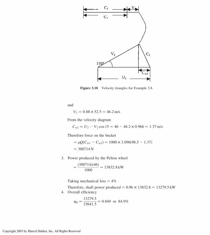
V2 ¼ 0:88 £ 52:5 ¼ 46:2m/s
From the velocity diagram
Cw2 ¼ U2 2 V2 cos 15 ¼ 462 46:2 £ 0:966 ¼ 1:37m/s
Therefore force on the bucket
¼ rQðCw1 2 Cw2Þ ¼ 1000 £ 3:096ð98:52 1:37Þ¼ 300714N
3. Power produced by the Pelton wheel
¼ ð300714Þð46Þ1000
¼ 13832:8 kW
Taking mechanical loss ¼ 4%
Therefore, shaft power produced ¼ 0.96 £ 13832.8 ¼ 13279.5 kW
4. Overall efficiency
ho ¼ 13279:5
15641:5¼ 0:849 or 84:9%
Figure 3.10 Velocity triangles for Example 3.8.
Chapter 3106
Copyright 2003 by Marcel Dekker, Inc. All Rights Reserved
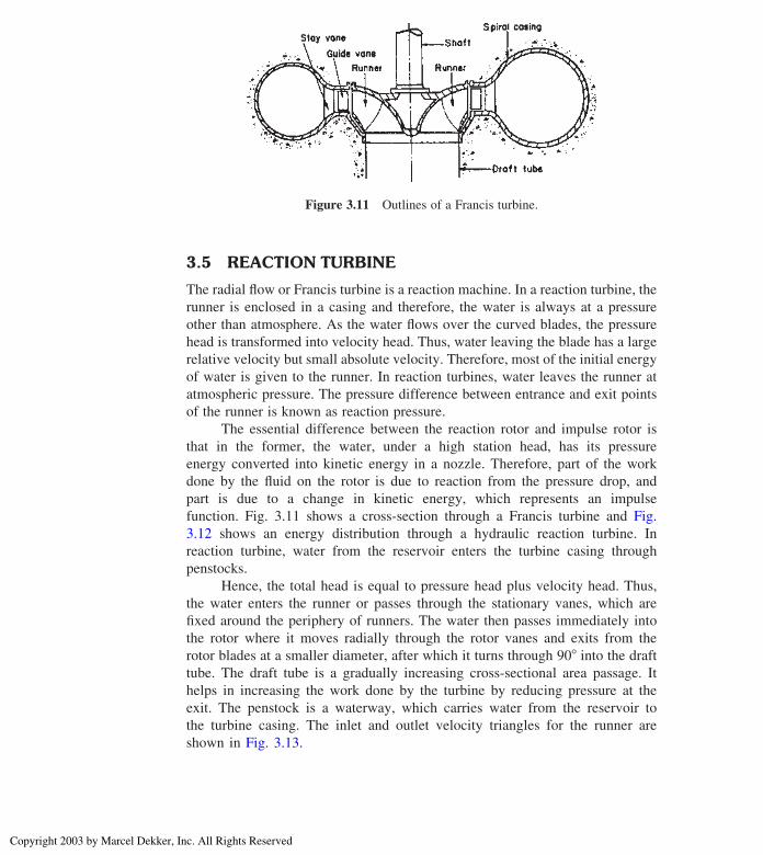
3.5 REACTION TURBINE
The radial flow or Francis turbine is a reaction machine. In a reaction turbine, the
runner is enclosed in a casing and therefore, the water is always at a pressure
other than atmosphere. As the water flows over the curved blades, the pressure
head is transformed into velocity head. Thus, water leaving the blade has a large
relative velocity but small absolute velocity. Therefore, most of the initial energy
of water is given to the runner. In reaction turbines, water leaves the runner at
atmospheric pressure. The pressure difference between entrance and exit points
of the runner is known as reaction pressure.
The essential difference between the reaction rotor and impulse rotor is
that in the former, the water, under a high station head, has its pressure
energy converted into kinetic energy in a nozzle. Therefore, part of the work
done by the fluid on the rotor is due to reaction from the pressure drop, and
part is due to a change in kinetic energy, which represents an impulse
function. Fig. 3.11 shows a cross-section through a Francis turbine and Fig.
3.12 shows an energy distribution through a hydraulic reaction turbine. In
reaction turbine, water from the reservoir enters the turbine casing through
penstocks.
Hence, the total head is equal to pressure head plus velocity head. Thus,
the water enters the runner or passes through the stationary vanes, which are
fixed around the periphery of runners. The water then passes immediately into
the rotor where it moves radially through the rotor vanes and exits from the
rotor blades at a smaller diameter, after which it turns through 908 into the draft
tube. The draft tube is a gradually increasing cross-sectional area passage. It
helps in increasing the work done by the turbine by reducing pressure at the
exit. The penstock is a waterway, which carries water from the reservoir to
the turbine casing. The inlet and outlet velocity triangles for the runner are
shown in Fig. 3.13.
Figure 3.11 Outlines of a Francis turbine.
Hydraulic Turbines 107
Copyright 2003 by Marcel Dekker, Inc. All Rights Reserved
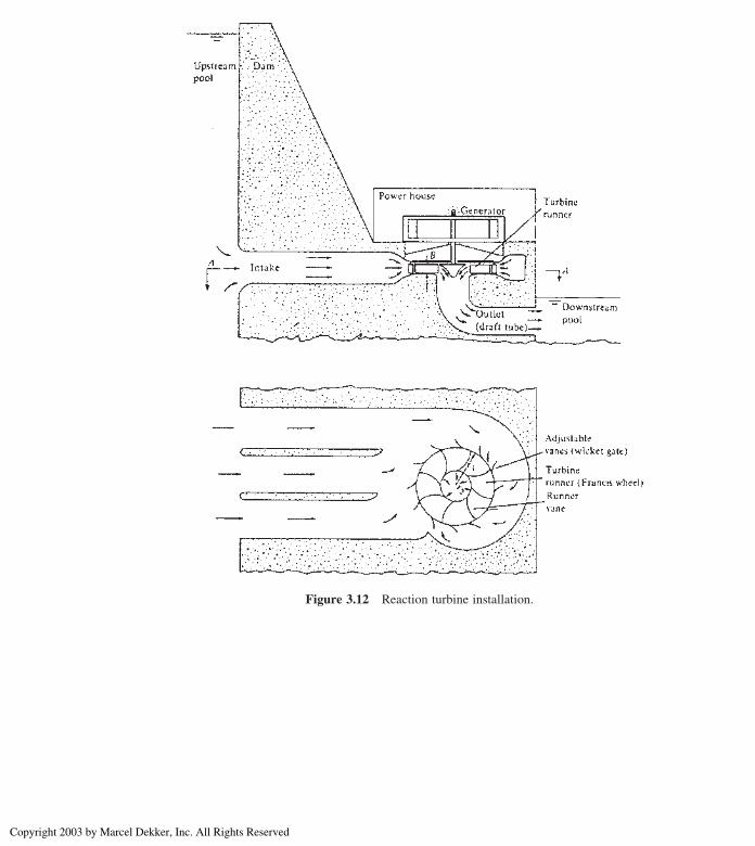
Figure 3.12 Reaction turbine installation.
Chapter 3108
Copyright 2003 by Marcel Dekker, Inc. All Rights Reserved
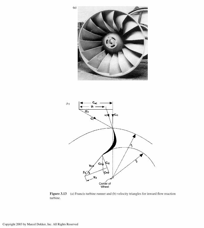
Figure 3.13 (a) Francis turbine runner and (b) velocity triangles for inward flow reaction
turbine.
Hydraulic Turbines 109
Copyright 2003 by Marcel Dekker, Inc. All Rights Reserved

Let
C1 ¼ Absolute velocity of water at inlet
D1 ¼ Outer diameter of the runner
N ¼ Revolution of the wheel per minute
U1 ¼ Tangential velocity of wheel at inlet
V1 ¼ Relative velocity at inlet
Cr1 ¼ radial velocity at inlet
a1 ¼ Angle with absolute velocity to the direction of motion
b1 ¼ Angle with relative velocity to the direction of motion
H ¼ Total head of water under which turbine is working
C2;D2;U2;V2;Cr2 ¼ Corresponding values at outlet
Euler’s turbine equation Eq. (1.78) and E is maximum when Cw2 (whirl
velocity at outlet) is zero that is when the absolute and flow velocities are equal at
the outlet.
3.6 TURBINE LOSSES
Let
Ps ¼ Shaft power output
Pm ¼ Mechanical power loss
Pr ¼ Runner power loss
Pc ¼ Casing and draft tube loss
Pl ¼ Leakage loss
P ¼ Water power available
Ph ¼ Pr þ Pc þ Pl ¼ Hydraulic power loss
Runner power loss is due to friction, shock at impeller entry, and flow
separation. If hf is the head loss associated with a flow rate through the runner of
Qr, then
Ps ¼ rgQrhf ðNm/sÞ ð3:8ÞLeakage power loss is due to leakage in flow rate, q, past the runner and therefore
not being handled by the runner. Thus
Q ¼ Qr þ q ð3:9Þ
Chapter 3110
Copyright 2003 by Marcel Dekker, Inc. All Rights Reserved

If Hr is the head across the runner, the leakage power loss becomes
Pl ¼ rgHrq ðNm / sÞ ð3:10ÞCasing power loss, Pc, is due to friction, eddy, and flow separation losses in the
casing and draft tube. If hc is the head loss in casing then
Pc ¼ rgQhc ðNm / sÞ ð3:11ÞFrom total energy balance we have
rgQH ¼ Pm þ rgðhfQr þ hcQþ Hrqþ PsÞThen overall efficiency, ho, is given by
ho ¼ Shaft power output
Fluid power available at inlet
or
ho ¼ Ps
rgQHð3:12Þ
Hydraulic efficiency, hh, is given by
hh ¼ Power available at runner
Fluid power available at inlet
or
hh ¼ ðPs þ PmÞrgQH
ð3:13Þ
Eq. (3.13) is the theoretical energy transfer per unit weight of fluid.
Therefore the maximum efficiency is
hh ¼ U1Cw1/gH ð3:14Þ
3.7 TURBINE CHARACTERISTICS
Part and overload characteristics of Francis turbines for specific speeds of 225
and 360 rpm are shown in Fig. 3.14
Figure 3.14 shows that machines of low specific speeds have a slightly
higher efficiency. It has been experienced that the Francis turbine has unstable
characteristics for gate openings between 30 to 60%, causing pulsations in output
and pressure surge in penstocks. Both these problems were solved by Paul Deriaz
by designing a runner similar to Francis runner but with adjustable blades.
The part-load performance of the various types are compared in Fig. 3.15
showing that the Kaplan and Pelton types are best adopted for a wide range of
load but are followed fairly closely by Francis turbines of low specific speed.
Hydraulic Turbines 111
Copyright 2003 by Marcel Dekker, Inc. All Rights Reserved

Figure 3.14 Variation of efficiency with load for Francis turbines.
Figure 3.15 Comparison of part-load efficiencies of various types of hydraulic turbine.
Chapter 3112
Copyright 2003 by Marcel Dekker, Inc. All Rights Reserved

3.8 AXIAL FLOW TURBINE
In an axial flow reaction turbine, also known as Kaplan turbine, the flow of water
is parallel to the shaft.
A Kaplan turbine is used where a large quantity of water is available at low
heads and hence the blades must be long and have large chords so that they are
strong enough to transmit the very high torque that arises. Fig. 3.16 and 3.17 shows
the outlines of the Kaplan turbine. The water from the scroll flows over the guide
blades and then over the vanes. The inlet guide vanes are fixed and are situated at a
plane higher than the runner blades such that fluidmust turn through 908 to enter therunner in the axial direction. The function of the guide vanes is to impart whirl to
the fluid so that the radial distribution of velocity is the same as in a free vortex.
Fig. 3.18 shows the velocity triangles and are usually drawn at the mean
radius, since conditions change from hub to tip. The flow velocity is axial at inlet
and outlet, hence Cr1 ¼ Cr2 ¼ Ca
C1 is the absolute velocity vector at anglea1 toU1, andV1 is the relative
velocity at an angle b1. For maximum efficiency, the whirl component Cw2 ¼ 0,
in which case the absolute velocity at exit is axial and then C2 ¼ Cr2
Using Euler’s equation
E ¼ UðCw1 2 Cw2Þ/gand for zero whirl (Cw2 ¼ 0) at exit
E ¼ UCw1/g
3.9 CAVITATION
In the design of hydraulic turbine, cavitation is an important factor. As the outlet
velocity V2 increases, then p2 decreases and has its lowest value when the vapor
pressure is reached.
At this pressure, cavitation begins. The Thoma parameter s ¼ NPSHH
and
Fig. 3.19 give the permissible value of sc in terms of specific speed.
The turbines of high specific speed have a high critical value of s, and must
therefore be set lower than those of smaller specific speed (Ns).
Illustrative Example 3.9: Consider an inward flow reaction turbine in
which velocity of flow at inlet is 3.8m/s. The 1m diameter wheel rotates at
240 rpm and absolute velocity makes an angle of 168 with wheel tangent.
Determine (1) velocity of whirl at inlet, (2) absolute velocity of water at inlet, (3)
vane angle at inlet, and (4) relative velocity of water at entrance.
Hydraulic Turbines 113
Copyright 2003 by Marcel Dekker, Inc. All Rights Reserved
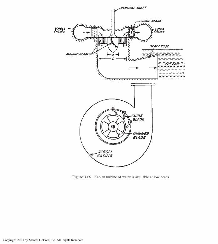
Figure 3.16 Kaplan turbine of water is available at low heads.
Chapter 3114
Copyright 2003 by Marcel Dekker, Inc. All Rights Reserved

Solution: From Fig. 3.13b
1. From inlet velocity triangle (subscript 1)
tana1 ¼ Cr1
Cw1
or Cw1 ¼ Cr1
tana1
¼ 3:8
tan168¼ 13:3m/s
2. Absolute velocity of water at inlet, C1, is
sina1 ¼ Cr1
C1
or C1 ¼ Cr1
sina1
¼ 3:8
sin168¼ 13:79m/s
3.
U1 ¼ ðpD1ÞðNÞ60
¼ ðpÞð1Þð240Þ60
¼ 12:57m/s
Figure 3.17 Kaplan turbine runner.
Hydraulic Turbines 115
Copyright 2003 by Marcel Dekker, Inc. All Rights Reserved

and
tanb1 ¼ Cr1
ðCw1 2 U1Þ ¼3:8
ð13:32 12:57Þ ¼3:8
0:73¼ 5:21
[ b1 ¼ 798 nearby
4. Relative velocity of water at entrance
sinb1 ¼ Cr1
V1
or V1 ¼ Cr1
sinb1
¼ 3:8
sin 798¼ 3:87m/s
Illustrative Example 3.10: The runner of an axial flow turbine has mean
diameter of 1.5m, and works under the head of 35m. The guide blades make an
angle of 308 with direction of motion and outlet blade angle is 228. Assuming
axial discharge, calculate the speed and hydraulic efficiency of the turbine.
Figure 3.18 Velocity triangles for an axial flow hydraulic turbine.
Chapter 3116
Copyright 2003 by Marcel Dekker, Inc. All Rights Reserved
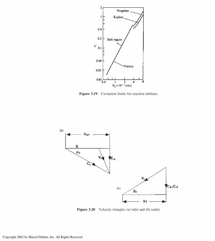
Figure 3.19 Cavitation limits for reaction turbines.
Figure 3.20 Velocity triangles (a) inlet and (b) outlet.
Hydraulic Turbines 117
Copyright 2003 by Marcel Dekker, Inc. All Rights Reserved
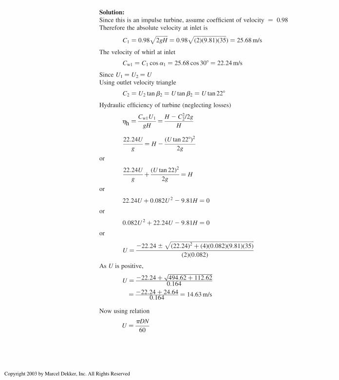
Solution:
Since this is an impulse turbine, assume coefficient of velocity ¼ 0.98
Therefore the absolute velocity at inlet is
C1 ¼ 0:98ffiffiffiffiffiffiffiffiffi2gH
p ¼ 0:98ffiffiffiffiffiffiffiffiffiffiffiffiffiffiffiffiffiffiffiffiffiffiffiffið2Þð9:81Þð35
pÞ ¼ 25:68m/s
The velocity of whirl at inlet
Cw1 ¼ C1 cosa1 ¼ 25:68 cos 308 ¼ 22:24m/s
Since U1 ¼ U2 ¼ U
Using outlet velocity triangle
C2 ¼ U2 tanb2 ¼ U tanb2 ¼ U tan 228
Hydraulic efficiency of turbine (neglecting losses)
hh ¼ Cw1U1
gH¼ H 2 C2
2/2g
H
22:24U
g¼ H 2
ðU tan 228Þ22g
or
22:24U
gþ ðU tan 22Þ2
2g¼ H
or
22:24U þ 0:082U 2 2 9:81H ¼ 0
or
0:082U 2 þ 22:24U 2 9:81H ¼ 0
or
U ¼ 222:24^ffiffiffiffiffiffiffiffiffiffiffiffiffiffiffiffiffiffiffiffiffiffiffiffiffiffiffiffiffiffiffiffiffiffiffiffiffiffiffiffiffiffiffiffiffiffiffiffiffiffiffiffiffiffiffiffiffiffiffiffiffiffið22:24Þ2 þ ð4Þð0:082Þð9:81Þð35Þ
p
ð2Þð0:082ÞAs U is positive,
U ¼ 222:24þ ffiffiffiffiffiffiffiffiffiffiffiffiffiffiffiffiffiffiffiffiffiffiffiffiffiffiffiffiffiffiffiffiffi494:62þ 112:62
p0:164
¼ 222:24þ 24:640:164 ¼ 14:63m/s
Now using relation
U ¼ pDN
60
Chapter 3118
Copyright 2003 by Marcel Dekker, Inc. All Rights Reserved
or
N ¼ 60U
pD¼ ð60Þð14:63Þ
ðpÞð1:5Þ ¼ 186 rpm
Hydraulic efficiency
hh ¼ Cw1U
gH¼ ð22:24Þð14:63Þ
ð9:81Þð35Þ ¼ 0:948 or 94:8%
Illustrative Example 3.11: A Kaplan runner develops 9000 kW under a
head of 5.5m. Assume a speed ratio of 2.08, flow ratio 0.68, and mechanical
efficiency 85%. The hub diameter is 1/3 the diameter of runner. Find the diameter
of the runner, and its speed and specific speed.
Solution:
U1 ¼ 2:08ffiffiffiffiffiffiffiffiffi2gH
p ¼ 2:08ffiffiffiffiffiffiffiffiffiffiffiffiffiffiffiffiffiffiffiffiffiffiffiffiffiffiffið2Þð9:81Þð5:5Þ
p¼ 21:61m/s
Cr1 ¼ 0:68ffiffiffiffiffiffiffiffiffi2gH
p ¼ 0:68ffiffiffiffiffiffiffiffiffiffiffiffiffiffiffiffiffiffiffiffiffiffiffiffiffiffiffið2Þð9:81Þð5:5Þ
p¼ 7:06m/s
Now power is given by
9000 ¼ ð9:81Þð5:5Þð0:85ÞQTherefore,
Q ¼ 196:24m3/s
If D is the runner diameter and, d, the hub diameter
Q ¼ p
4ðD2 2 d 2ÞCr1
or
p
4D2 2
1
9D2
� �7:06 ¼ 196:24
Solving
D ¼ffiffiffiffiffiffiffiffiffiffiffiffiffiffiffiffiffiffiffiffiffiffiffiffiffiffiffiffið196:24Þð4Þð9ÞðpÞð7:06Þð8Þ
r¼ 6:31m
Ns ¼ NffiffiffiP
pH 5/4 ¼ 65
ffiffiffiffiffiffiffiffiffiffi9000
p5:55/4
¼ 732 rpm
Design Example 3.12: A propeller turbine develops 12,000 hp, and rotates
at 145 rpm under a head of 20m. The outer and hub diameters are 4m and 1.75m,
Hydraulic Turbines 119
Copyright 2003 by Marcel Dekker, Inc. All Rights Reserved
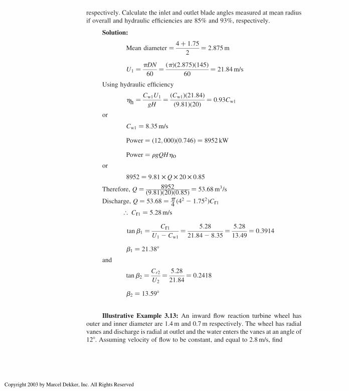
respectively. Calculate the inlet and outlet blade angles measured at mean radius
if overall and hydraulic efficiencies are 85% and 93%, respectively.
Solution:
Mean diameter ¼ 4þ 1:75
2¼ 2:875m
U1 ¼ pDN
60¼ ðpÞð2:875Þð145Þ
60¼ 21:84m/s
Using hydraulic efficiency
hh ¼ Cw1U1
gH¼ ðCw1Þð21:84Þ
ð9:81Þð20Þ ¼ 0:93Cw1
or
Cw1 ¼ 8:35m/s
Power ¼ ð12; 000Þð0:746Þ ¼ 8952 kW
Power ¼ rgQHho
or
8952 ¼ 9:81 £ Q £ 20 £ 0:85
Therefore, Q ¼ 8952ð9:81Þð20Þð0:85Þ ¼ 53:68m3/s
Discharge, Q ¼ 53:68 ¼ p4ð42 2 1:752ÞCr1
[ Cr1 ¼ 5:28m/s
tanb1 ¼ Cr1
U1 2 Cw1
¼ 5:28
21:842 8:35¼ 5:28
13:49¼ 0:3914
b1 ¼ 21:388
and
tanb2 ¼ Cr2
U2
¼ 5:28
21:84¼ 0:2418
b2 ¼ 13:598
Illustrative Example 3.13: An inward flow reaction turbine wheel has
outer and inner diameter are 1.4m and 0.7m respectively. The wheel has radial
vanes and discharge is radial at outlet and the water enters the vanes at an angle of
128. Assuming velocity of flow to be constant, and equal to 2.8m/s, find
Chapter 3120
Copyright 2003 by Marcel Dekker, Inc. All Rights Reserved

1. The speed of the wheel, and
2. The vane angle at outlet.
Solution:
Outer diameter, D2 ¼ 1.4m
Inner diameter, D1 ¼ 0.7m
Angle at which the water enters the vanes, a1 ¼ 128Velocity of flow at inlet,
Cr1 ¼ Cr2 ¼ 2:8m/s
As the vanes are radial at inlet and outlet end, the velocity of whirl at inlet
and outlet will be zero, as shown in Fig. 3.21.
Tangential velocity of wheel at inlet,
U1 ¼ Cr1
tan 128¼ 2:8
0:213¼ 13:15m/s
Also, U1 ¼ pD2N60
or
N ¼ 60U1
pD2
¼ ð60Þð13:15ÞðpÞð1:4Þ ¼ 179 rpm
Figure 3.21 Velocity triangles at inlet and outlet for Example 3.13.
Hydraulic Turbines 121
Copyright 2003 by Marcel Dekker, Inc. All Rights Reserved
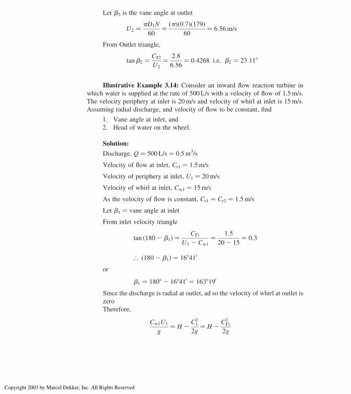
Let b2 is the vane angle at outlet
U2 ¼ pD1N
60¼ ðpÞð0:7Þð179Þ
60¼ 6:56m/s
From Outlet triangle,
tanb2 ¼ Cr2
U2
¼ 2:8
6:56¼ 0:4268 i:e: b2 ¼ 23:118
Illustrative Example 3.14: Consider an inward flow reaction turbine in
which water is supplied at the rate of 500 L/s with a velocity of flow of 1.5m/s.
The velocity periphery at inlet is 20m/s and velocity of whirl at inlet is 15m/s.
Assuming radial discharge, and velocity of flow to be constant, find
1. Vane angle at inlet, and
2. Head of water on the wheel.
Solution:
Discharge, Q ¼ 500 L/s ¼ 0.5m3/s
Velocity of flow at inlet, Cr1 ¼ 1.5m/s
Velocity of periphery at inlet, U1 ¼ 20m/s
Velocity of whirl at inlet, Cw1 ¼ 15m/s
As the velocity of flow is constant, Cr1 ¼ Cr2 ¼ 1.5m/s
Let b1 ¼ vane angle at inlet
From inlet velocity triangle
tan ð1802 b1Þ ¼ Cr1
U1 2 Cw1
¼ 1:5
202 15¼ 0:3
[ ð1802 b1Þ ¼ 168410
or
b1 ¼ 1808 2 168410 ¼ 1638190
Since the discharge is radial at outlet, ad so the velocity of whirl at outlet is
zero
Therefore,
Cw1U1
g¼ H 2
C21
2g¼ H 2
C2r12g
Chapter 3122
Copyright 2003 by Marcel Dekker, Inc. All Rights Reserved
or
ð15Þð20Þ9:81
¼ H 21:52
ð2Þð9:81Þ[ H ¼ 30:582 0:1147 ¼ 30:47m
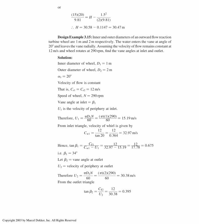
DesignExample 3.15: Inner and outer diameters of an outwardflow reaction
turbine wheel are 1m and 2m respectively. The water enters the vane at angle of
208 and leaves the vane radially. Assuming the velocity of flow remains constant at
12m/s and wheel rotates at 290 rpm, find the vane angles at inlet and outlet.
Solution:
Inner diameter of wheel, D1 ¼ 1m
Outer diameter of wheel, D2 ¼ 2m
a1 ¼ 208
Velocity of flow is constant
That is, Cr1 ¼ Cr2 ¼ 12m/s
Speed of wheel, N ¼ 290 rpm
Vane angle at inlet ¼ b1
U1 is the velocity of periphery at inlet.
Therefore, U1 ¼ pD1N60
¼ ðpÞð1Þð290Þ60
¼ 15:19m/s
From inlet triangle, velocity of whirl is given by
Cw1 ¼ 12
tan 20¼ 12
0:364¼ 32:97m/s
Hence, tanb1 ¼ Cr1Cw1 2 U1
¼ 1232:972 15:19
¼ 1217:78 ¼ 0:675
i.e. b1 ¼ 348
Let b2 ¼ vane angle at outlet
U2 ¼ velocity of periphery at outlet
Therefore U2 ¼ pD2N
60¼ ðpÞð2Þð290Þ
60¼ 30:38m/s
From the outlet triangle
tanb2 ¼ Cr2
U2
¼ 12
30:38¼ 0:395
Hydraulic Turbines 123
Copyright 2003 by Marcel Dekker, Inc. All Rights Reserved
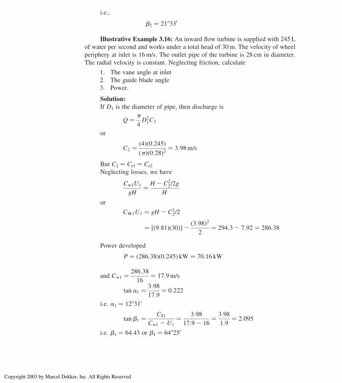
i.e.,
b2 ¼ 218330
Illustrative Example 3.16: An inward flow turbine is supplied with 245 L
of water per second and works under a total head of 30m. The velocity of wheel
periphery at inlet is 16m/s. The outlet pipe of the turbine is 28 cm in diameter.
The radial velocity is constant. Neglecting friction, calculate
1. The vane angle at inlet
2. The guide blade angle
3. Power.
Solution:
If D1 is the diameter of pipe, then discharge is
Q ¼ p
4D2
1C2
or
C2 ¼ ð4Þð0:245ÞðpÞð0:28Þ2 ¼ 3:98m/s
But C2 ¼ Cr1 ¼ Cr2
Neglecting losses, we have
Cw1U1
gH¼ H 2 C2
2/2g
H
or
Cw1U1 ¼ gH 2 C22/2
¼ ½ð9:81Þð30Þ�2 ð3:98Þ22
¼ 294:32 7:92 ¼ 286:38
Power developed
P ¼ ð286:38Þð0:245Þ kW ¼ 70:16 kW
and Cw1 ¼ 286:38
16¼ 17:9m/s
tana1 ¼ 3:98
17:9¼ 0:222
i.e. a1 ¼ 128310
tanb1 ¼ Cr1
Cw1 2 U1
¼ 3:98
17:92 16¼ 3:98
1:9¼ 2:095
i.e. b1 ¼ 64.43 or b1 ¼ 648250
Chapter 3124
Copyright 2003 by Marcel Dekker, Inc. All Rights Reserved

Design Example 3.17: A reaction turbine is to be selected from the
following data:
Discharge ¼ 7:8m3/s
Shaft power ¼ 12; 400 kW
Pressure head in scroll casing
at the entrance to turbine ¼ 164m of water
Elevation of turbine casing above tail water level ¼ 5:4m
Diameter of turbine casing ¼ 1m
Velocity in tail race ¼ 1:6m/s
Calculate the effective head on the turbine and the overall efficiency of the
unit.
Solution:
Velocity in casing at inlet to turbine
Cc ¼ DischargeCross 2 sectional area of casing
¼ 7:8ðp/4Þð1Þ2 ¼ 9:93m/s
The net head on turbine
¼ Pressure headþ Head due to turbine positionþ C2c 2 C2
12g
¼ 164þ 5:4þ ð9:93Þ2 2 ð1:6Þ22g
¼ 164þ 5:4þ 98:62 2:5619:62 ¼ 174:3m of water
Waterpower supplied to turbine ¼ QgH kW
¼ ð7:8Þð9:81Þð174:3Þ ¼ 13; 337 kW
Hence overall efficiency,
ho ¼ Shaft Power
Water Power¼ 12; 400
13; 337¼ 0:93 or 93%
Design Example 3.18: A Francis turbine wheel rotates at 1250 rpm and net
head across the turbine is 125m. The volume flow rate is 0.45m3/s, radius of the
runner is 0.5m. The height of the runner vanes at inlet is 0.035m. and the angle of
Hydraulic Turbines 125
Copyright 2003 by Marcel Dekker, Inc. All Rights Reserved
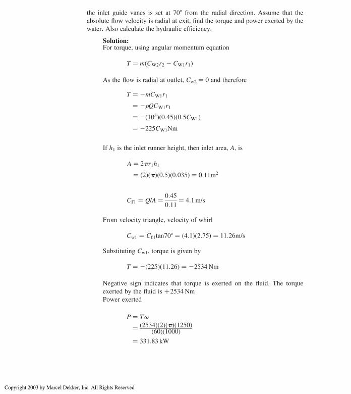
the inlet guide vanes is set at 708 from the radial direction. Assume that the
absolute flow velocity is radial at exit, find the torque and power exerted by the
water. Also calculate the hydraulic efficiency.
Solution:For torque, using angular momentum equation
T ¼ mðCw2r2 2 Cw1r1Þ
As the flow is radial at outlet, Cw2 ¼ 0 and therefore
T ¼ 2mCw1r1
¼ 2rQCw1r1
¼ 2ð103Þð0:45Þð0:5Cw1Þ¼ 2225Cw1Nm
If h1 is the inlet runner height, then inlet area, A, is
A ¼ 2pr1h1
¼ ð2ÞðpÞð0:5Þð0:035Þ ¼ 0:11m2
Cr1 ¼ Q/A ¼ 0:45
0:11¼ 4:1m/s
From velocity triangle, velocity of whirl
Cw1 ¼ Cr1tan708 ¼ ð4:1Þð2:75Þ ¼ 11:26m/s
Substituting Cw1, torque is given by
T ¼ 2ð225Þð11:26Þ ¼ 22534Nm
Negative sign indicates that torque is exerted on the fluid. The torque
exerted by the fluid is þ2534Nm
Power exerted
P ¼ Tv
¼ ð2534Þð2ÞðpÞð1250Þð60Þð1000Þ
¼ 331:83 kW
Chapter 3126
Copyright 2003 by Marcel Dekker, Inc. All Rights Reserved

Hydraulic efficiency is given by
hh ¼ Power exertedPower available
¼ ð331:83Þð103ÞrgQH
¼ 331:83 £ 103
ð103Þð9:81Þð0:45Þð125Þ¼ 0:6013 ¼ 60:13%
Design Example 3.19: An inward radial flow turbine develops 130 kW
under a head of 5m. The flow velocity is 4m/s and the runner tangential velocity at
inlet is 9.6m/s. The runner rotates at 230 rpmwhile hydraulic losses accounting for
20% of the energy available. Calculate the inlet guide vane exit angle, the inlet
angle to the runner vane, the runner diameter at the inlet, and the height of the
runner at inlet. Assume radial discharge, and overall efficiency equal to 72%.
Solution:Hydraulic efficiency is
hh ¼ Power delelopedPower available
¼ mðCw1U1 2 Cw2UÞrgQH
Since flow is radial at outlet, then Cw2 ¼ 0 and m ¼ rQ, therefore
hh ¼ Cw1U1
gH
0:80 ¼ ðCw1Þð9:6Þð9:81Þð5Þ
Cw1 ¼ ð0:80Þð9:81Þð5Þ9:6
¼ 4:09m/s
Radial velocity Cr1 ¼ 4m/s
tana1 ¼ Cr1/Cw1 ðfrom velocity triangleÞ¼ 4
4:09 ¼ 0:978
Hydraulic Turbines 127
Copyright 2003 by Marcel Dekker, Inc. All Rights Reserved

i.e., inlet guide vane angle a1 ¼ 448210
tanb1 ¼ Cr1
Cw1 2 U1ð Þ
¼ 4
4:092 9:6ð Þ ¼4
25:51¼ 20:726
i.e., b1 ¼ 235.988 or 1808 2 35.98 ¼ 144.028Runner speed is
U1 ¼ pD1N
60
or
D1 ¼ 60U1
pN¼ ð60Þð9:6Þ
ðpÞð230ÞD1 ¼ 0:797m
Overall efficiency
ho ¼ Power output
Power available
or
rgQH ¼ ð130Þð103Þ0:72
or
Q ¼ ð130Þð103Þð0:72Þð103Þð9:81Þð5Þ ¼ 3:68m3/s
But
Q ¼ pD1h1Cr1ðwhere h1is the height of runnerÞTherefore,
h1 ¼ 3:68
ðpÞð0:797Þð4Þ ¼ 0:367m
Illustrative Example 3.20: The blade tip and hub diameters of an axial
hydraulic turbine are 4.50m and 2m respectively. The turbine has a net head of
22m across it and develops 22MW at a speed of 150 rpm. If the hydraulic
efficiency is 92% and the overall efficiency 84%, calculate the inlet and outlet
blade angles at the mean radius assuming axial flow at outlet.
Chapter 3128
Copyright 2003 by Marcel Dekker, Inc. All Rights Reserved
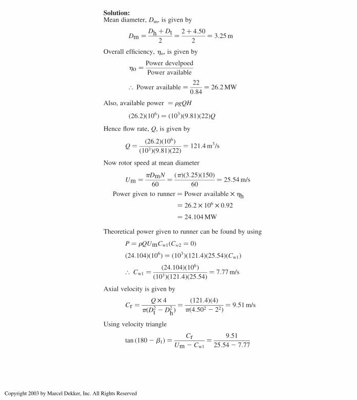
Solution:Mean diameter, Dm, is given by
Dm ¼ Dh þ Dt
2¼ 2þ 4:50
2¼ 3:25m
Overall efficiency, ho, is given by
ho ¼ Power develpoed
Power available
[ Power available ¼ 22
0:84¼ 26:2MW
Also, available power ¼ rgQH
ð26:2Þð106Þ ¼ ð103Þð9:81Þð22ÞQHence flow rate, Q, is given by
Q ¼ ð26:2Þð106Þð103Þð9:81Þð22Þ ¼ 121:4m3/s
Now rotor speed at mean diameter
Um ¼ pDmN
60¼ ðpÞð3:25Þð150Þ
60¼ 25:54m/s
Power given to runner ¼ Power available £ hh
¼ 26:2 £ 106 £ 0:92
¼ 24:104MW
Theoretical power given to runner can be found by using
P ¼ rQUmCw1ðCw2 ¼ 0Þð24:104Þð106Þ ¼ ð103Þð121:4Þð25:54ÞðCw1Þ
[ Cw1 ¼ ð24:104Þð106Þð103Þð121:4Þð25:54Þ ¼ 7:77m/s
Axial velocity is given by
Cr ¼ Q £ 4
pðD2t 2 D2
hÞ¼ ð121:4Þð4Þ
pð4:502 2 22Þ ¼ 9:51m/s
Using velocity triangle
tan ð1802 b1Þ ¼ Cr
Um 2 Cw1
¼ 9:51
25:542 7:77
Hydraulic Turbines 129
Copyright 2003 by Marcel Dekker, Inc. All Rights Reserved

Inlet angle,
b1 ¼ 151:858
At outlet
tanb2 ¼ Cr
Vcw2
But Vcw2 equals to Um since Cw2 is zero. Hence
tanb2 ¼ 9:51
25:54¼ 0:3724
that is,
b2 ¼ 20:438
Design Example 3.21: The following design data apply to an inward flow
radial turbine:
Overall efficiency 75%
Net head across the turbine 6m
Power output 128 kW
The runner tangential velocity 10:6m/s
Flow velocity 4m/s
Runner rotational speed 235 rpm
Hydraulic losses 18% of energy available
Calculate the inlet guide vane angle, the inlet angle of the runner vane, the
runner diameter at inlet, and height of the runner at inlet. Assume that the
discharge is radial.
Solution:
Hydraulic efficiency, hh, is given by
hh ¼ Power given to runnerWater Power available
¼ m U1Cw1 2 U2Cw2ð ÞrgQH
Since flow is radial at exit, Cw2 ¼ 0 and m ¼ rQ. Therefore
hh ¼ U1Cw1
gH
0:82 ¼ ð10:6ÞðCw1Þð9:81Þð6Þ or Cw1 ¼ 4:6m/s
Chapter 3130
Copyright 2003 by Marcel Dekker, Inc. All Rights Reserved

Now
tana1 ¼ Cr1/Cw1 ¼ 4
4:6¼ 0:8695
that is;a1 ¼ 418
From Figs. 3.22 and 3.23
tan ð1802 b1Þ ¼ Cr1
U1 2 Cw1
¼ 4
10:62 4:6¼ 0:667
that is; b1 ¼ 33:698
Hence blade angle, b1, is given by
1808 2 33:698 ¼ 146:318
Runner speed at inlet
U1 ¼ pD1N
60
Figure 3.22 Velocity triangles for Example 3.14.
Hydraulic Turbines 131
Copyright 2003 by Marcel Dekker, Inc. All Rights Reserved
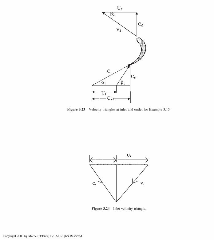
Figure 3.23 Velocity triangles at inlet and outlet for Example 3.15.
Figure 3.24 Inlet velocity triangle.
Chapter 3132
Copyright 2003 by Marcel Dekker, Inc. All Rights Reserved
or
D1 ¼ U1ð60ÞpN
¼ ð10:6Þð60ÞðpÞð235Þ ¼ 0:86m
Overall efficiency
ho ¼ Power output
Power available
rgQH ¼ ð128Þð103Þ0:75
From which flow rate
Q ¼ ð128Þð103Þð0:75Þð103Þð9:81Þð6Þ ¼ 2:9m3/s
Also,
Q ¼ pD1hCr1
where h1 is the height of runner
Therefore,
h1 ¼ 2:9
ðpÞð0:86Þð4Þ ¼ 0:268m
Design Example 3.22: A Kaplan turbine develops 10,000 kW under an
effective head 8m. The overall efficiency is 0.86, the speed ratio 2.0, and flow
ratio 0.60. The hub diameter of the wheel is 0.35 times the outside diameter of
the wheel. Find the diameter and speed of the turbine.
Solution:Head, H ¼ 8m, Power, P ¼ 10,000 kW
Overall efficiency, ho ¼ 0.86
Speed ratio
2 ¼ U1
ð2gHÞ1=2 ; or Ul ¼ffiffiffiffiffiffiffiffiffiffiffiffiffiffiffiffiffiffiffiffiffiffiffiffi2 £ 9:81 £ 8
p ¼ 25:06m/s
Flow ratio
Cr1
ð2gHÞ1=2 ¼ 0:60 or Cr1 ¼ 0:60ffiffiffiffiffiffiffiffiffiffiffiffiffiffiffiffiffiffiffiffiffiffiffiffi2 £ 9:81 £ 8
p ¼ 7:52m/s
Hub diameter, D1 ¼ 0.35 D2
Hydraulic Turbines 133
Copyright 2003 by Marcel Dekker, Inc. All Rights Reserved
Overall efficiency,
ho ¼ P
rgQH
Or
0:86 ¼ 10000
1000 £ 9:81 £ Q £ 8
[ Q ¼ 148:16m3/s
Now using the relation
Q ¼ Cr1 £ p
4D2
1 2 D22
Or
148:16 ¼ 7:52 £ p
4D2
1 2 0:35D21
� �
[ D1 ¼ 5:35m
The peripheral velocity of the turbine at inlet
25:06 ¼ pD1N
60¼ p £ 5:35 £ N
60
[ N ¼ 60 £ 25:06
p £ 5:35¼ 89 rpm
Design Example 3.23: An inward flow reaction turbine, having an inner
and outer diameter of 0.45m and 0.90m, respectively. The vanes are radial at
inlet and the discharge is radial at outlet and the water enters the vanes at an angle
of 128. Assuming the velocity of flow as constant and equal to 2.8m/s, find the
speed of the wheel and the vane angle at outlet.
Solution:
Inner Diameter, D2 ¼ 0.45m
Outer Diameter, D1 ¼ 0.9m
a2 ¼ 908ðradial dischargeÞ
a1 ¼ 128;Cr1 ¼ Cr2 ¼ 2:8m/s
Chapter 3134
Copyright 2003 by Marcel Dekker, Inc. All Rights Reserved

From velocity triangle at inlet (see Fig. 3.11), The peripheral velocity of the
wheel at inlet
U1 ¼ Cr1
tana1
¼ 2:8
tan 128¼ 13:173m/s
Now,
U1 ¼ pD1N
60
or
N ¼ 60U1
pD1
¼ 60 £ 13:173
p £ 0:9¼ 279 rpm
Considering velocity triangle at outlet peripheral velocity at outlet
U2 ¼ pD2N
60¼ p £ 0:45 £ 279
60¼ 6:58m/s
tanb2 ¼ Cr2
U2
¼ 2:8
6:58¼ 0:426
[ b2 ¼ 23:058
Design Example 3.24: An inward flow reaction turbine develops 70 kW at
370 rpm. The inner and outer diameters of the wheel are 40 and 80 cm,
respectively. The velocity of the water at exit is 2.8m/s. Assuming that the
discharge is radial and that the width of the wheel is constant, find the actual and
theoretical hydraulic efficiencies of the turbine and the inlet angles of the guide
and wheel vanes. Turbine discharges 545 L/s under a head of 14m.
Solution:
Q ¼ 545 L/s ¼ 0.545m3/s
D1 ¼ 80 cm, D2 ¼ 40 cm
H ¼ 14m, a2 ¼ 908 (radial discharge)
b1 ¼ b2
Peripheral velocity of the wheel at inlet
U1 ¼ pD1N
60¼ p £ 0:80 £ 370
60¼ 15:5m/s
Velocity of flow at the exit, Cr2 ¼ 2.8m/s
As a2 ¼ 908, Cr2 ¼ C2
Work done/s by the turbine per kg of water ¼ Cw£U1
g
Hydraulic Turbines 135
Copyright 2003 by Marcel Dekker, Inc. All Rights Reserved
But this is equal to the head utilized by the turbine, i.e.
Cw1U1
g¼ H 2
C2
2g
(Assuming there is no loss of pressure at outlet) or
Cw1 £ 15:5
9:81¼ 142
ð2:8Þ22 £ 9:81
¼ 13:6m
or
Cw1 ¼ 13:6 £ 9:81
15:5¼ 8:6m/s
Work done per second by turbine
¼ rQgCw1U1
¼ 1000 £ 0:545 £ 8:6 £ 15:51000
¼ 72:65kW
Available power or water power ¼ rgQH1000
¼ 74:85
Actual available power ¼ 70 kW
Overall turbine efficiency isht ¼70
74:85£ 100
ht ¼ 93:52%
This is the actual hydraulic efficiency as required in the problem.
Hydraulic Efficiency is
hh ¼ 72:65
75:85£ 100 ¼ 97:06%
This is the theoretical efficiency
Q ¼ pD1b1Cr1 ¼ pD2b2Cr2
(Neglecting blade thickness)
Cr1 ¼ Cr2
D2
D1
¼ 2:8 £ 40
20¼ 1:4m/s
Drawing inlet velocity triangle
tanb1 ¼ Cr1
U1 2 Cw1
¼ 1:4
15:52 8:6¼ 1:4
6:9¼ 0:203
Chapter 3136
Copyright 2003 by Marcel Dekker, Inc. All Rights Reserved
i.e., b1 ¼ 11.478
C1 ¼ffiffiffiffiffiffiffiffiffiffiffiffiffiffiffiffiffiffiffiffiffiCw1 þ Cr1
p¼ 8:62 þ 1:42
� �0:5¼ 8:64m/s
and
cosa1 ¼ Cw1
C1
¼ 8:6
8:64¼ 0:995
i.e., a1 ¼ 5.58
Design Example 3.25: An inward flow Francis turbine, having an overall
efficiency of 86%, hydraulic efficiency of 90%, and radial velocity of flow at inlet
0.28ffiffiffiffiffiffiffiffiffi2gH
p. The turbine is required to develop 5000 kW when operating under a
net head of 30m, specific speed is 270, assume guide vane angle 308, find
1. rpm of the wheel,
2. the diameter and the width of the runner at inlet, and
3. the theoretical inlet angle of the runner vanes.
Solution:
Power, P ¼ 5000 kW;a1 ¼ 308;H ¼ 30m;Cr1 ¼ 0:28ffiffiffiffiffiffiffiffiffi2gH
p, Ns ¼ 270,
hh ¼ 0.90, ho ¼ 0.86
1. Specific speed of the turbine is
Ns ¼ NffiffiffiP
p
H5=4
or
N ¼ NsH5=4
ffiffiffiP
p ¼ 270 £ ð30Þ1:25ffiffiffiffiffiffiffiffiffiffi5000
p ¼ 18957
71¼ 267 rpm
2. Velocity of Flow:
Cr1 ¼ 0:28ffiffiffiffiffiffiffiffiffiffiffiffiffiffiffiffiffiffiffiffiffiffiffiffiffiffiffi2 £ 9:81 £ 30
p ¼ 6:79m/s
From inlet velocity triangle
Cr1 ¼ C1sina1
or
6:79 ¼ C1sin 308
or
C1 ¼ 6:79
0:5¼ 13:58m/s
Cw1 ¼ C1 cos308 ¼ 13.58 £ 0.866 ¼ 11.76m/s
Hydraulic Turbines 137
Copyright 2003 by Marcel Dekker, Inc. All Rights Reserved
Work done per (sec) (kg) of water
¼ Cw1 £ U1
g¼ hh £ H
¼ 0:9 £ 30
¼ 27mkg/s
Peripheral Velocity,
U1 ¼ 27 £ 9:81
11:76¼ 22:5m/s
But U1 ¼ pD1N60
or
D1 ¼ 60U1
pN¼ 60 £ 22:5
p £ 267¼ 1:61m
Power, P ¼ rgQHho
or
5000 ¼ 1000 £ 9.81 £ Q £ 30 £ 0.86
or
Q ¼ 19.8m3/s
Also Q ¼ kpD1b1Cr1 (where k is the blade thickness coefficient and b1is the breath of the wheel at inlet) or
b1 ¼ Q
kpD1Cr1
¼ 19:8
0:95 £ p £ 1:61 £ 6:79¼ 0:61m
3. From inlet velocity triangle
tanb1 ¼ Cr1
U1 2 Cw1
¼ 6:79
22:52 11:76¼ 6:79
10:74¼ 0:632
i.e. b1 ¼ 32.308
Design Example 3.26: A 35MW generator is to operate by a double
overhung Pelton wheel. The effective head is 350m at the base of the nozzle.
Find the size of jet, mean diameter of the runner and specific speed of wheel.
Assume Pelton wheel efficiency 84%, velocity coefficient of nozzle 0.96, jet ratio
12, and speed ratio 0.45.
Solution:
In this case, the generator is fed by two Pelton turbines.
Chapter 3138
Copyright 2003 by Marcel Dekker, Inc. All Rights Reserved

Power developed by each turbine,
PT ¼ 35; 000
2¼ 17; 500 kW
Using Pelton wheel efficiency in order to find available power of each
turbine
P ¼ 17; 500
0:84¼ 20; 833 kW
But, P ¼ rgQH
Q ¼ P
rgH¼ 20833
1000 £ 9:81 £ 350¼ 6:07m3/s
Velocity of jet,Cj ¼ Cvffiffiffiffiffiffiffiffiffi2gH
p ¼ 0:96ffiffiffiffiffiffiffiffiffiffiffiffiffiffiffiffiffiffiffiffiffiffiffiffiffiffiffiffiffi2 £ 9:81 £ 350
p
Cj ¼ 79:6m/s
Area of jet, A ¼ QCj¼ 6:07
79:6 ¼ 0:0763m2
[ Diameter of jet,d ¼ 4Ap
� �0:5¼ 4 £ 0:0763p
� �0:5¼ 0:312m
d ¼ 31:2 cm
Diameter of wheel D ¼ d £ jet ratio ¼ 0.312 £ 12 ¼ 3.744m
Peripheral velocity of the wheel
U ¼ speed ratioffiffiffiffiffiffiffiffiffi2gH
p
¼ 0:45 £ ffiffiffiffiffiffiffiffiffiffiffiffiffiffiffiffiffiffiffiffiffiffiffiffiffiffiffiffiffi2 £ 9:81 £ 350
p ¼ 37:29m/s
But U ¼ pDN60
or
N ¼ 60U
pD¼ 60 £ 37:29
p £ 3:744¼ 190 rpm
Specific speed,
Ns ¼ NffiffiffiffiffiffiPT
pH 5=4
¼ 190ffiffiffiffiffiffiffiffiffiffiffiffiffiffiffi17; 500
pð350Þ1:25 ¼ 16:6
PROBLEMS
3.1 A Pelton wheel produces 4600 hP under a head of 95m, and with an overall
efficiency of 84%. Find the diameter of the nozzle if the coefficient of
velocity for the nozzle is 0.98.
(0.36m)
Hydraulic Turbines 139
Copyright 2003 by Marcel Dekker, Inc. All Rights Reserved
3.2 Pelton wheel develops 13,500 kW under a head of 500m. The wheel rotates
at 430 rpm. Find the size of the jet and the specific speed. Assume 85%
efficiency.
(0.21m, 21)
3.3 A Pelton wheel develops 2800 bhP under a head of 300m at 84% efficiency.
The ratio of peripheral velocity of wheel to jet velocity is 0.45 and specific
speed is 17. Assume any necessary data and find the jet diameter.
(140mm)
3.4 A Pelton wheel of power station develops 30,500 hP under a head of 1750m
while running at 760 rpm. Calculate (1) the mean diameter of the runner,
(2) the jet diameter, and (3) the diameter ratio.
(2.14m, 0.104m, 20.6)
3.5 Show that in an inward flow reaction turbine, when the velocity of flow is
constant and wheel vane angle at entrance is 908, the best peripheral
velocity is
ffiffiffiffiffiffiffiffiffi2gH
p/
ffiffiffiffiffiffiffiffiffiffiffiffiffiffiffiffiffiffiffiffi2þ tan2a
p
where H is the head and a the angle of guide vane.
3.6 A Pelton wheel develops 740 kW under a head of 310m. Find the jet
diameter if its efficiency is 86% and
Cv ¼ 0:98:
(0.069m)
3.7 A reaction turbine runner diameter is 3.5m at inlet and 2.5m at outlet.
The turbine discharge 102m3 per second of water under a head of
145m. Its inlet vane angle is 1208. Assume radial discharge at 14m/s,
breadth of wheel constant and hydraulic efficiency of 88%, calculate
the power developed and speed of machine.
(128MW, 356 rpm)
3.8 Show that in a Pelton wheel, where the buckets deflect the water through an
angle of (1808 2 a) degrees, the hydraulic efficiency of thewheel is given by
hh ¼ 2UðC 2 UÞð1þ cosaÞC 2
where C is the velocity of jet and U is mean blade velocity.
3.9 A Kaplan turbine produces 16000 kW under a head of 20m, while running
at 166 rpm. The diameter of the runner is 4.2m while the hub diameter is
2m, the discharge being 120m3/s. Calculate (1) the turbine efficiency,
Chapter 3140
Copyright 2003 by Marcel Dekker, Inc. All Rights Reserved

(2) specific speed, (3) the speed ratio based on the tip diameter of the blade,
and (4) the flow ratio.
(78%, 497, 1.84, 0.48)
3.10 Evolve a formula for the specific speed of a Pelton wheel in the following
form
Ns ¼ k� ffiffiffiffiffiffiffih�p d
D
where Ns ¼ specific speed, h ¼ overall efficiency, d ¼ diameter of jet,
D ¼ diameter of bucket circle, and k ¼ a constant.
NOTATION
C jet velocity, absolute
Cv nozzle velocity coefficient
Cw velocity of whirl
D wheel diameter
d diameter of nozzle
E energy transfer by bucket
Hr head across the runner
hf frictional head loss
Ns specific speed
P water power available
Pc casing and draft tube losses
Ph hydraulic power loss
Pl leakage loss
Pm mechanical power loss
Pr runner power loss
Ps shaft power output
U bucket speed
W work done
a angle of the blade tip at outlet
b angle with relative velocity
hi nozzle efficiency
htrans transmission efficiency
k relative velocity ratio
Hydraulic Turbines 141
Copyright 2003 by Marcel Dekker, Inc. All Rights Reserved


![لﻮﺻا ﻲﺑﺎﻳرازﺎﺑsv.20file.org/up1/1437_0.pdfZZZ 3UR]KHKD LU ﻪﺑ ﻢﻳﺪﻘﺗ ،مﺮﺘﺧد و مﺮﺴﻤﻫ ﻦﻴﻤﺳﺎﻳ و ﻢﻳﺮﻣ ZZZ 3UR]KHKD](https://static.fdocuments.us/doc/165x107/5f744978100e183e04671820/ii-iiiiiisv-zzz-3urkhkd-lu-ii-iiiii-oeiii.jpg)


