Tunable bioelectrodes with wrinkled-ridged graphene …whong/papers/68.pdf · Tunable bioelectrodes...
12
Tunable bioelectrodes with wrinkled-ridged graphene oxide surfaces for electrochemical nitrate sensors† Md. Azahar Ali, a Wei Hong, b Seval Oren, a Qiugu Wang, a Yifei Wang, a Huawei Jiang a and Liang Dong * a The paper reports on controlled formation of microscale wrinkles and ridges on the surface of a bioelectrode via mechanical stretching to tune and optimize the electrochemical sensing performances of graphene oxide (GO) based nitrate ion sensors. The bioelectrode consists of GO nanosheets drop-coated on a gold (Au) layer with a pre-stretched elastomer substrate. Enzyme nitrate reductase is used for covalent immobilization on the wrinkled-ridged GO surface. Upon relaxation from the pre-stretch, wrinkles or ridges are formed in the GO layer. As the pre-stretch increases, the sinusoidal wrinkles transform to localized ridges on the surface of bioelectrodes. Such morphological transitions, realized by simple mechanical stretching and relaxing, allow optimizing of the electrochemical current and sensing characteristics of the nitrate sensor. The sensing performances of the bioelectrodes at different pre-stretches are investigated. In addition to an increased electroactive surface area, the predominant localized ridges with small sinusoidal wrinkles formed on the GO surface provide a favorable spatial feature, enabling efficient radial diffusion of nitrate ions from surrounding analyte solutions onto the surface of the textured bioelectrode. At the pre-stretch of 8%, the nitrate sensor using the wrinkled-ridged bioelectrode exhibits a considerably high sensitivity of 0.224 mAL mol 1 cm 2 in response to nitrate ions, which is five times higher than that provided by the planar counterpart. Also, the textured bioelectrode shows high selectivity even in the presence of other inferring ions. The present nitrate sensor has potential applications in nitrate detection in sustainable agriculture, environmental monitoring, food analysis, and pharmaceutical industries. 1. Introduction High-sensitivity, high-selectivity monitoring of nitrate ions (NO 3 ) with inexpensive portable devices is highly appealing for a vast variety of applications, including in sustainable agricul- ture, environmental monitoring, food analysis, and pharma- ceutical industries. 1–4 Extensive use of nitrate fertilizers in agriculture has negatively impacted ground water, soil, and marine ecosystems. The presence of enriched nitrate ions in food products also has a potential human health threat. Common practice for nitrate detection includes using ion exchange chromatography, spectrophotometry, 5 colorimetric sensors, 6 ion-selective electrodes, and ion-sensitive eld effect transistors. Due to its high signal-to-noise ratio and low limit-of- detection, electrochemical means of nitrate detection has been in high demand, which oen relies on using different sensitive materials, such as methyl viologen/Naon, 1 polypyrrole, 2 hydrophilic poly(pyrrole-viologen), 3 1-methyl-3-(pyrrol-1-yl- methyl)pyridinium microporous membrane, 4 CNT–poly- pyrrole, 7 polypyrrole, 8 platinum–tin, 9 and silver particle–poly- methacrylic-acid. 10 Despite these efforts, there is still much room to improve sensitivity, operational stability, and/or anti- fouling capability for nitrate sensors. 1,2 Graphene and graphene oxide (GO) have shown great potential in many research areas, including point-of-care diag- nostics or therapeutics, 11,12 microelectronics, 13,14 optoelec- tronics, 15 sensors, 16 and energy storage, 17 due to various attractive properties, such as large surface area, high mechan- ical strength, high integer quantum Hall effect, and ballistic conduction of charge carriers. 18 By varying pore size, geometry, surface area, and functional sites through structural and morphological transformation of GO, it is possible to tune electrical, chemical, and mechanical properties of GO to meet the needs of specic applications. 19–21 Single-layer GO nano- sheets are known to contain several oxygen-containing groups (e.g., epoxy and hydroxyl) at the basal plane, and carboxyls and ring lactols groups at the edges of GO nanosheets. 22,23 Since these abundant binding sites can form strong covalent bonds a Department of Electrical and Computer Engineering, Iowa State University, Ames, IA, 50011, USA. E-mail: [email protected]; Tel: +515-294-0388 b Department of Aerospace Engineering, Iowa State University, Ames, IA, 50011, USA † Electronic supplementary information (ESI) available. See DOI: 10.1039/c6ra09621b Cite this: RSC Adv. , 2016, 6, 67184 Received 13th April 2016 Accepted 10th July 2016 DOI: 10.1039/c6ra09621b www.rsc.org/advances 67184 | RSC Adv. , 2016, 6, 67184–67195 This journal is © The Royal Society of Chemistry 2016 RSC Advances PAPER Published on 11 July 2016. Downloaded by Iowa State University on 27/01/2017 17:45:11. View Article Online View Journal | View Issue
Transcript of Tunable bioelectrodes with wrinkled-ridged graphene …whong/papers/68.pdf · Tunable bioelectrodes...
RSC Advances
PAPER
Publ
ishe
d on
11
July
201
6. D
ownl
oade
d by
Iow
a St
ate
Uni
vers
ity o
n 27
/01/
2017
17:
45:1
1.
View Article OnlineView Journal | View Issue
Tunable bioelect
aDepartment of Electrical and Computer Eng
50011, USA. E-mail: [email protected]; TelbDepartment of Aerospace Engineering, Iowa
† Electronic supplementary informa10.1039/c6ra09621b
Cite this: RSC Adv., 2016, 6, 67184
Received 13th April 2016Accepted 10th July 2016
DOI: 10.1039/c6ra09621b
www.rsc.org/advances
67184 | RSC Adv., 2016, 6, 67184–6719
rodes with wrinkled-ridgedgraphene oxide surfaces for electrochemicalnitrate sensors†
Md. Azahar Ali,a Wei Hong,b Seval Oren,a Qiugu Wang,a Yifei Wang,a Huawei Jianga
and Liang Dong*a
The paper reports on controlled formation of microscale wrinkles and ridges on the surface of
a bioelectrode via mechanical stretching to tune and optimize the electrochemical sensing
performances of graphene oxide (GO) based nitrate ion sensors. The bioelectrode consists of GO
nanosheets drop-coated on a gold (Au) layer with a pre-stretched elastomer substrate. Enzyme nitrate
reductase is used for covalent immobilization on the wrinkled-ridged GO surface. Upon relaxation from
the pre-stretch, wrinkles or ridges are formed in the GO layer. As the pre-stretch increases, the
sinusoidal wrinkles transform to localized ridges on the surface of bioelectrodes. Such morphological
transitions, realized by simple mechanical stretching and relaxing, allow optimizing of the
electrochemical current and sensing characteristics of the nitrate sensor. The sensing performances of
the bioelectrodes at different pre-stretches are investigated. In addition to an increased electroactive
surface area, the predominant localized ridges with small sinusoidal wrinkles formed on the GO surface
provide a favorable spatial feature, enabling efficient radial diffusion of nitrate ions from surrounding
analyte solutions onto the surface of the textured bioelectrode. At the pre-stretch of 8%, the nitrate
sensor using the wrinkled-ridged bioelectrode exhibits a considerably high sensitivity of 0.224 mA L
mol�1 cm�2 in response to nitrate ions, which is five times higher than that provided by the planar
counterpart. Also, the textured bioelectrode shows high selectivity even in the presence of other
inferring ions. The present nitrate sensor has potential applications in nitrate detection in sustainable
agriculture, environmental monitoring, food analysis, and pharmaceutical industries.
1. Introduction
High-sensitivity, high-selectivity monitoring of nitrate ions(NO3
�) with inexpensive portable devices is highly appealing fora vast variety of applications, including in sustainable agricul-ture, environmental monitoring, food analysis, and pharma-ceutical industries.1–4 Extensive use of nitrate fertilizers inagriculture has negatively impacted ground water, soil, andmarine ecosystems. The presence of enriched nitrate ions infood products also has a potential human health threat.Common practice for nitrate detection includes using ionexchange chromatography, spectrophotometry,5 colorimetricsensors,6 ion-selective electrodes, and ion-sensitive eld effecttransistors. Due to its high signal-to-noise ratio and low limit-of-detection, electrochemical means of nitrate detection has beenin high demand, which oen relies on using different sensitive
ineering, Iowa State University, Ames, IA,
: +515-294-0388
State University, Ames, IA, 50011, USA
tion (ESI) available. See DOI:
5
materials, such as methyl viologen/Naon,1 polypyrrole,2
hydrophilic poly(pyrrole-viologen),3 1-methyl-3-(pyrrol-1-yl-methyl)pyridinium microporous membrane,4 CNT–poly-pyrrole,7 polypyrrole,8 platinum–tin,9 and silver particle–poly-methacrylic-acid.10 Despite these efforts, there is still muchroom to improve sensitivity, operational stability, and/or anti-fouling capability for nitrate sensors.1,2
Graphene and graphene oxide (GO) have shown greatpotential in many research areas, including point-of-care diag-nostics or therapeutics,11,12 microelectronics,13,14 optoelec-tronics,15 sensors,16 and energy storage,17 due to variousattractive properties, such as large surface area, high mechan-ical strength, high integer quantum Hall effect, and ballisticconduction of charge carriers.18 By varying pore size, geometry,surface area, and functional sites through structural andmorphological transformation of GO, it is possible to tuneelectrical, chemical, and mechanical properties of GO to meetthe needs of specic applications.19–21 Single-layer GO nano-sheets are known to contain several oxygen-containing groups(e.g., epoxy and hydroxyl) at the basal plane, and carboxyls andring lactols groups at the edges of GO nanosheets.22,23 Sincethese abundant binding sites can form strong covalent bonds
This journal is © The Royal Society of Chemistry 2016
Paper RSC Advances
Publ
ishe
d on
11
July
201
6. D
ownl
oade
d by
Iow
a St
ate
Uni
vers
ity o
n 27
/01/
2017
17:
45:1
1.
View Article Online
with proteins, enzymes, antibodies, and nucleotides via ami-dation reaction,24 many chemical and biological sensors, suchas paracetamol sensors,25 rotavirus sensors,22 and tuberculosissensors,23 have been realized utilizing the interactive oxygenframework in GO nanosheets. Also, GO nanosheets providelarge amounts of open graphitic edge planes with high surfacereactivity, thus offering a promising nanostructured materialfor electrochemical biosensors.26,27 Recently, self-assembledfree-standing, graphene–Naon nanohybrids have been devel-oped to form exible biosensors for organophosphate detec-tion, which excel in high conductivity, electron transfer, and lowinterfacial resistance.27 An amperometric nitrate sensor wasrealized using a reduced GOmodied glassy carbon electrode.28
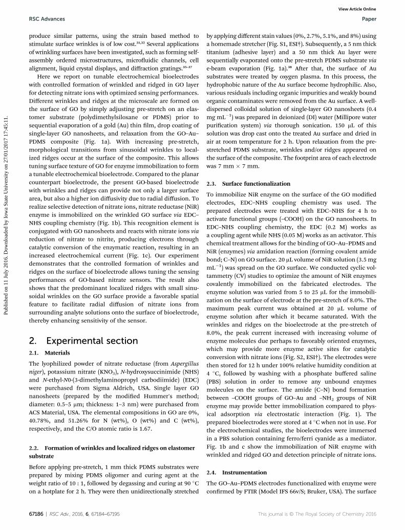
Fig. 1 Pictorial representation of the nitrate sensor using a GO–Au bioewrinkles and/or ridges. (b) Surface functionalization of enzyme moleculesensor to different nitrate ion concentrations.
This journal is © The Royal Society of Chemistry 2016
Wrinkled electrophoretic deposited graphene lm has beendeveloped for electrochemical detection of explosivecompounds.29 In addition, vertical multilayer graphene nano-sheets have demonstrated fast electron-transfer kinetics andgood electrocatalytic activity to monitor dopamine, ascorbicacid, and uric acid.30
In recent years, surface wrinkling of a stiff thin lm supportedby a compliant thick substrate has received much attention.31,32
Under a critical strain, the surface of the lm loses the stabilityand forms different wrinkle morphologies, such as sinusoidal,herringbone, checkerboard, and hexagonal modes due todifferent uniaxial to biaxial compression.33,34 Although conven-tional photolithography and micromachining methods can
lectrode with a wrinkled and/or ridged surface. (a) Method of formings. (c) Sensing mechanism and typical electrochemical responses of the
RSC Adv., 2016, 6, 67184–67195 | 67185
RSC Advances Paper
Publ
ishe
d on
11
July
201
6. D
ownl
oade
d by
Iow
a St
ate
Uni
vers
ity o
n 27
/01/
2017
17:
45:1
1.
View Article Online
produce similar patterns, using the strain based method tostimulate surface wrinkles is of low cost.31,32 Several applicationsof wrinkling surfaces have been investigated, such as forming self-assembly ordered microstructures, microuidic channels, cellalignment, liquid crystal displays, and diffraction gratings.35–37
Here we report on tunable electrochemical bioelectrodeswith controlled formation of wrinkled and ridged in GO layerfor detecting nitrate ions with optimized sensing performances.Different wrinkles and ridges at the microscale are formed onthe surface of GO by simply adjusting pre-stretch on an elas-tomer substrate (polydimethylsiloxane or PDMS) prior tosequential evaporation of a gold (Au) thin lm, drop coating ofsingle-layer GO nanosheets, and relaxation from the GO–Au–PDMS composite (Fig. 1a). With increasing pre-stretch,morphological transitions from sinusoidal wrinkles to local-ized ridges occur at the surface of the composite. This allowstuning surface texture of GO for enzyme immobilization to forma tunable electrochemical bioelectrode. Compared to the planarcounterpart bioelectrode, the present GO-based bioelectrodewith wrinkles and ridges can provide not only a larger surfacearea, but also a higher ion diffusivity due to radial diffusion. Torealize selective detection of nitrate ions, nitrate reductase (NiR)enzyme is immobilized on the wrinkled GO surface via EDC–NHS coupling chemistry (Fig. 1b). This recognition element isconjugated with GO nanosheets and reacts with nitrate ions viareduction of nitrate to nitrite, producing electrons throughcatalytic conversion of the enzymatic reaction, resulting in anincreased electrochemical current (Fig. 1c). Our experimentdemonstrates that the controlled formation of wrinkles andridges on the surface of bioelectrode allows tuning the sensingperformances of GO-based nitrate sensors. The result alsoshows that the predominant localized ridges with small sinu-soidal wrinkles on the GO surface provide a favorable spatialfeature to facilitate radial diffusion of nitrate ions fromsurrounding analyte solutions onto the surface of bioelectrode,thereby enhancing sensitivity of the sensor.
2. Experimental section2.1. Materials
The lyophilized powder of nitrate reductase (from Aspergillusniger), potassium nitrate (KNO3), N-hydroxysuccinimide (NHS)and N-ethyl-N0-(3-dimethylaminopropyl carbodiimide) (EDC)were purchased from Sigma Aldrich, USA. Single layer GOnanosheets (prepared by the modied Hummer's method;diameter: 0.5–5 mm; thickness: 1–3 nm) were purchased fromACS Material, USA. The elemental compositions in GO are 0%,40.78%, and 51.26% for N (wt%), O (wt%) and C (wt%),respectively, and the C/O atomic ratio is 1.67.
2.2. Formation of wrinkles and localized ridges on elastomersubstrate
Before applying pre-stretch, 1 mm thick PDMS substrates wereprepared by mixing PDMS oligomer and curing agent at theweight ratio of 10 : 1, followed by degassing and curing at 90 �Con a hotplate for 2 h. They were then unidirectionally stretched
67186 | RSC Adv., 2016, 6, 67184–67195
by applying different stain values (0%, 2.7%, 5.1%, and 8%) usinga homemade stretcher (Fig. S1, ESI†). Subsequently, a 5 nm thicktitanium (adhesive layer) and a 50 nm thick Au layer weresequentially evaporated onto the pre-stretch PDMS substrate viae-beam evaporation (Fig. 1a).38 Aer that, the surface of Ausubstrates were treated by oxygen plasma. In this process, thehydrophobic nature of the Au surface become hydrophilic. Also,various residuals including organic impurities and weakly boundorganic contaminates were removed from the Au surface. A well-dispersed colloidal solution of single-layer GO nanosheets (0.4mg mL�1) was prepared in deionized (DI) water (Millipore waterpurication system) via thorough sonication. 150 mL of thissolution was drop cast onto the treated Au surface and dried inair at room temperature for 2 h. Upon relaxation from the pre-stretched PDMS substrate, wrinkles and/or ridges appeared onthe surface of the composite. The footprint area of each electrodewas 7 mm � 7 mm.
2.3. Surface functionalization
To immobilize NiR enzyme on the surface of the GO modiedelectrodes, EDC–NHS coupling chemistry was used. Theprepared electrodes were treated with EDC–NHS for 4 h toactivate functional groups (–COOH) on the GO nanosheets. InEDC–NHS coupling chemistry, the EDC (0.2 M) works asa coupling agent while NHS (0.05 M) works as an activator. Thischemical treatment allows for the binding of GO–Au–PDMS andNiR (enzymes) via amidation reaction (forming covalent amidebond; C–N) on GO surface. 20 mL volume of NiR solution (3.5 mgmL�1) was spread on the GO surface. We conducted cyclic vol-tammetry (CV) studies to optimize the amount of NiR enzymescovalently immobilized on the fabricated electrodes. Theenzyme solution was varied from 5 to 25 mL for the immobili-zation on the surface of electrode at the pre-stretch of 8.0%. Themaximum peak current was obtained at 20 mL volume ofenzyme solution aer which it became saturated. With thewrinkles and ridges on the bioelectrode at the pre-stretch of8.0%, the peak current increased with increasing volume ofenzyme molecules due perhaps to favorably oriented enzymes,which may provide more enzyme active sites for catalyticconversion with nitrate ions (Fig. S2, ESI†). The electrodes werethen stored for 12 h under 100% relative humidity condition at4 �C, followed by washing with a phosphate buffered saline(PBS) solution in order to remove any unbound enzymesmolecules on the surface. The amide (C–N) bond formationbetween –COOH groups of GO–Au and –NH2 groups of NiRenzyme may provide better immobilization compared to phys-ical adsorption via electrostatic interaction (Fig. 1). Theprepared bioelectrodes were stored at 4 �C when not in use. Forthe electrochemical studies, the bioelectrodes were immersedin a PBS solution containing ferro/ferri cyanide as a mediator.Fig. 1b and c show the immobilization of NiR enzyme withwrinkled and ridged GO and detection principle of nitrate ions.
2.4. Instrumentation
The GO–Au–PDMS electrodes functionalized with enzyme wereconrmed by FTIR (Model IFS 66v/S; Bruker, USA). The surface
This journal is © The Royal Society of Chemistry 2016
Paper RSC Advances
Publ
ishe
d on
11
July
201
6. D
ownl
oade
d by
Iow
a St
ate
Uni
vers
ity o
n 27
/01/
2017
17:
45:1
1.
View Article Online
morphology was characterized by FE-SEM (Quanta-250; FEI,Hillsboro, OR, USA) and AFM (Veeco, Nanoscope 3D, USA.Raman microscope (Thermo Scientic, Waltham, MA, USA) wasused for Raman spectra acquisition with 532 nm excitation at 10mW, 10� objective, and 50 mmslit. The CV was performed usinga potentiostat (Model: DY2100; Digi-Ivy, TX, USA). HomemadePt and Ag/AgCl electrodes were used for counter and referenceelectrodes, respectively.
2.5. Modeling of surface morphology
To understand the evolution of the surface morphology, a seriesof nite-element simulation was carried out with the commer-cial soware SIMULIA Abaqus 6.12. A tri-layer lm–substratesystem was developed in the 2D rectangular domain. In thenumerical calculations, all lengths were normalized by thethickness of the graphene lm h, and all stresses by the initialshear modulus of the PDMS substrate, ms. The thickness of theAu layer was taken to be 5h, while that of the PDMS substratewas 400h. Symmetric boundary conditions were prescribed onthe le and right edges. The width of the entire domainmeasures 3000h before deformation. Within the small strain ofinterest, the graphene lm was considered to be linear elasticwith Young's modulus Eg ¼ 5 � 105ms and Poisson's ratio ng ¼0.2. The PDMS substrate was modeled as an incompressibleneo-Hookean material. The Au layer was modeled as elastic-
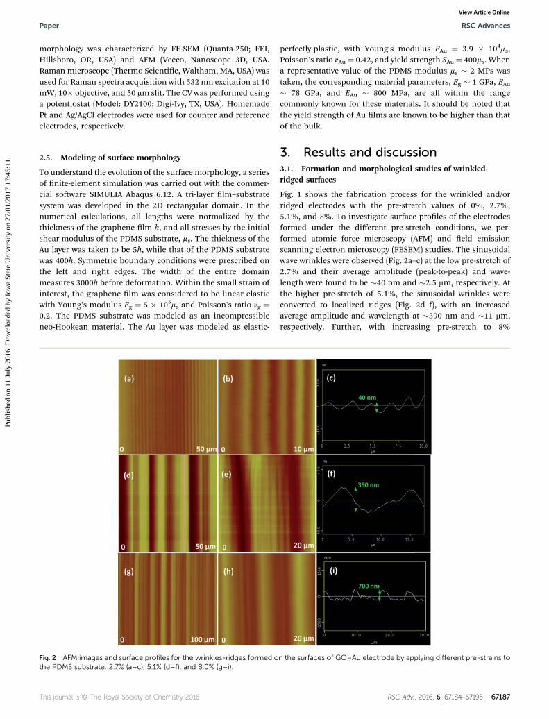
Fig. 2 AFM images and surface profiles for the wrinkles-ridges formed othe PDMS substrate: 2.7% (a–c), 5.1% (d–f), and 8.0% (g–i).
This journal is © The Royal Society of Chemistry 2016
perfectly-plastic, with Young's modulus EAu ¼ 3.9 � 104ms,Poisson's ratio nAu ¼ 0.42, and yield strength SAu ¼ 400ms. Whena representative value of the PDMS modulus ms � 2 MPs wastaken, the corresponding material parameters, Eg � 1 GPa, EAu� 78 GPa, and EAu � 800 MPa, are all within the rangecommonly known for these materials. It should be noted thatthe yield strength of Au lms are known to be higher than thatof the bulk.
3. Results and discussion3.1. Formation and morphological studies of wrinkled-ridged surfaces
Fig. 1 shows the fabrication process for the wrinkled and/orridged electrodes with the pre-stretch values of 0%, 2.7%,5.1%, and 8%. To investigate surface proles of the electrodesformed under the different pre-stretch conditions, we per-formed atomic force microscopy (AFM) and eld emissionscanning electron microscopy (FESEM) studies. The sinusoidalwave wrinkles were observed (Fig. 2a–c) at the low pre-stretch of2.7% and their average amplitude (peak-to-peak) and wave-length were found to be �40 nm and �2.5 mm, respectively. Atthe higher pre-stretch of 5.1%, the sinusoidal wrinkles wereconverted to localized ridges (Fig. 2d–f), with an increasedaverage amplitude and wavelength at �390 nm and �11 mm,respectively. Further, with increasing pre-stretch to 8%
n the surfaces of GO–Au electrode by applying different pre-strains to
RSC Adv., 2016, 6, 67184–67195 | 67187
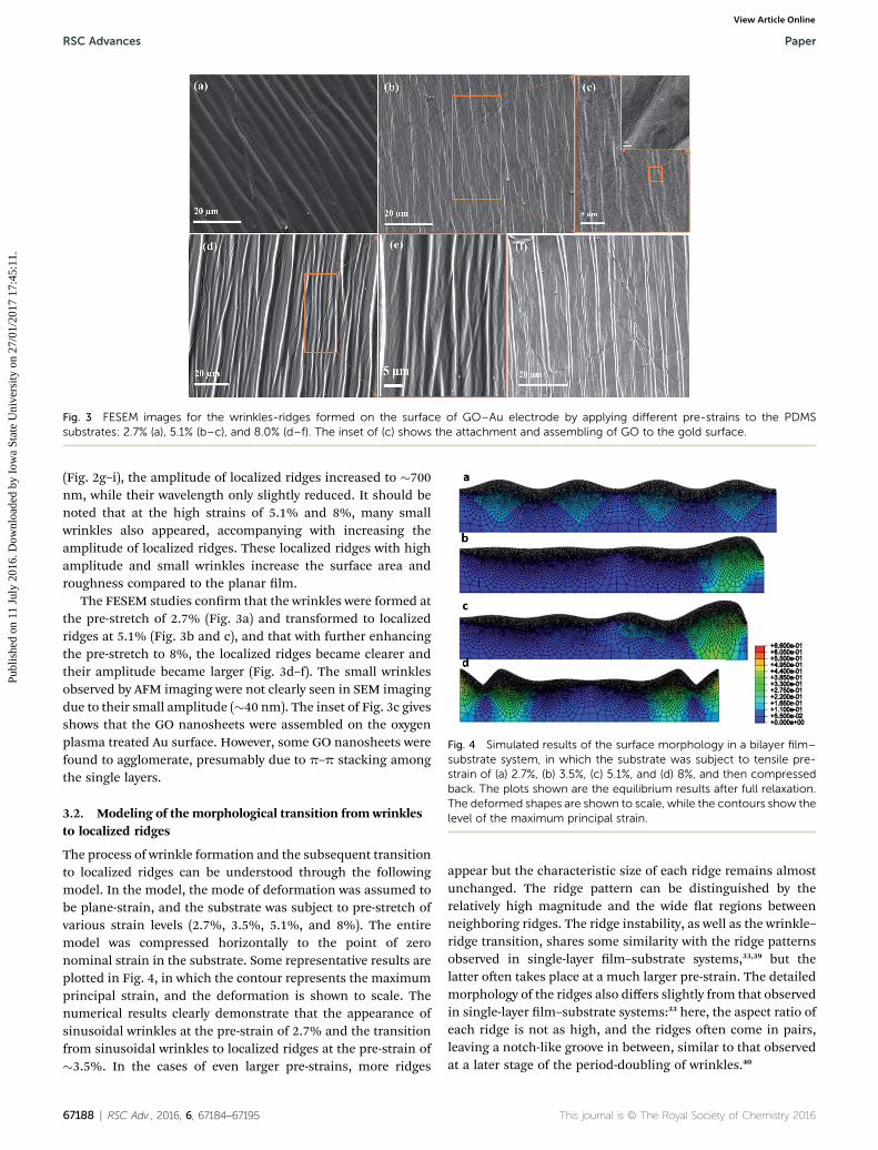
Fig. 3 FESEM images for the wrinkles-ridges formed on the surface of GO–Au electrode by applying different pre-strains to the PDMSsubstrates: 2.7% (a), 5.1% (b–c), and 8.0% (d–f). The inset of (c) shows the attachment and assembling of GO to the gold surface.
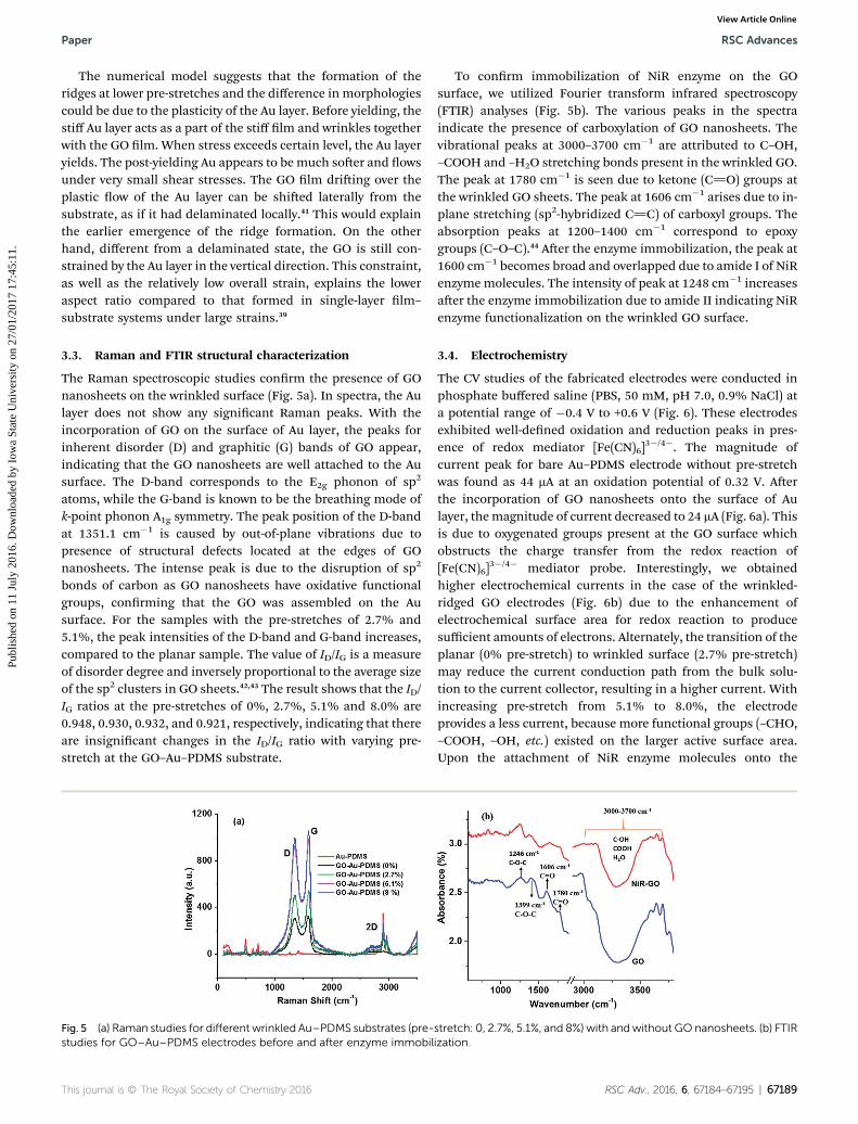
Fig. 4 Simulated results of the surface morphology in a bilayer film–substrate system, in which the substrate was subject to tensile pre-strain of (a) 2.7%, (b) 3.5%, (c) 5.1%, and (d) 8%, and then compressedback. The plots shown are the equilibrium results after full relaxation.The deformed shapes are shown to scale, while the contours show thelevel of the maximum principal strain.
RSC Advances Paper
Publ
ishe
d on
11
July
201
6. D
ownl
oade
d by
Iow
a St
ate
Uni
vers
ity o
n 27
/01/
2017
17:
45:1
1.
View Article Online
(Fig. 2g–i), the amplitude of localized ridges increased to �700nm, while their wavelength only slightly reduced. It should benoted that at the high strains of 5.1% and 8%, many smallwrinkles also appeared, accompanying with increasing theamplitude of localized ridges. These localized ridges with highamplitude and small wrinkles increase the surface area androughness compared to the planar lm.
The FESEM studies conrm that the wrinkles were formed atthe pre-stretch of 2.7% (Fig. 3a) and transformed to localizedridges at 5.1% (Fig. 3b and c), and that with further enhancingthe pre-stretch to 8%, the localized ridges became clearer andtheir amplitude became larger (Fig. 3d–f). The small wrinklesobserved by AFM imaging were not clearly seen in SEM imagingdue to their small amplitude (�40 nm). The inset of Fig. 3c givesshows that the GO nanosheets were assembled on the oxygenplasma treated Au surface. However, some GO nanosheets werefound to agglomerate, presumably due to p–p stacking amongthe single layers.
3.2. Modeling of the morphological transition from wrinklesto localized ridges
The process of wrinkle formation and the subsequent transitionto localized ridges can be understood through the followingmodel. In the model, the mode of deformation was assumed tobe plane-strain, and the substrate was subject to pre-stretch ofvarious strain levels (2.7%, 3.5%, 5.1%, and 8%). The entiremodel was compressed horizontally to the point of zeronominal strain in the substrate. Some representative results areplotted in Fig. 4, in which the contour represents the maximumprincipal strain, and the deformation is shown to scale. Thenumerical results clearly demonstrate that the appearance ofsinusoidal wrinkles at the pre-strain of 2.7% and the transitionfrom sinusoidal wrinkles to localized ridges at the pre-strain of�3.5%. In the cases of even larger pre-strains, more ridges
67188 | RSC Adv., 2016, 6, 67184–67195
appear but the characteristic size of each ridge remains almostunchanged. The ridge pattern can be distinguished by therelatively high magnitude and the wide at regions betweenneighboring ridges. The ridge instability, as well as the wrinkle–ridge transition, shares some similarity with the ridge patternsobserved in single-layer lm–substrate systems,33,39 but thelatter oen takes place at a much larger pre-strain. The detailedmorphology of the ridges also differs slightly from that observedin single-layer lm–substrate systems:33 here, the aspect ratio ofeach ridge is not as high, and the ridges oen come in pairs,leaving a notch-like groove in between, similar to that observedat a later stage of the period-doubling of wrinkles.40
This journal is © The Royal Society of Chemistry 2016
Paper RSC Advances
Publ
ishe
d on
11
July
201
6. D
ownl
oade
d by
Iow
a St
ate
Uni
vers
ity o
n 27
/01/
2017
17:
45:1
1.
View Article Online
The numerical model suggests that the formation of theridges at lower pre-stretches and the difference in morphologiescould be due to the plasticity of the Au layer. Before yielding, thestiff Au layer acts as a part of the stiff lm and wrinkles togetherwith the GO lm. When stress exceeds certain level, the Au layeryields. The post-yielding Au appears to bemuch soer and owsunder very small shear stresses. The GO lm driing over theplastic ow of the Au layer can be shied laterally from thesubstrate, as if it had delaminated locally.41 This would explainthe earlier emergence of the ridge formation. On the otherhand, different from a delaminated state, the GO is still con-strained by the Au layer in the vertical direction. This constraint,as well as the relatively low overall strain, explains the loweraspect ratio compared to that formed in single-layer lm–
substrate systems under large strains.39
3.3. Raman and FTIR structural characterization
The Raman spectroscopic studies conrm the presence of GOnanosheets on the wrinkled surface (Fig. 5a). In spectra, the Aulayer does not show any signicant Raman peaks. With theincorporation of GO on the surface of Au layer, the peaks forinherent disorder (D) and graphitic (G) bands of GO appear,indicating that the GO nanosheets are well attached to the Ausurface. The D-band corresponds to the E2g phonon of sp2
atoms, while the G-band is known to be the breathing mode ofk-point phonon A1g symmetry. The peak position of the D-bandat 1351.1 cm�1 is caused by out-of-plane vibrations due topresence of structural defects located at the edges of GOnanosheets. The intense peak is due to the disruption of sp2
bonds of carbon as GO nanosheets have oxidative functionalgroups, conrming that the GO was assembled on the Ausurface. For the samples with the pre-stretches of 2.7% and5.1%, the peak intensities of the D-band and G-band increases,compared to the planar sample. The value of ID/IG is a measureof disorder degree and inversely proportional to the average sizeof the sp2 clusters in GO sheets.42,43 The result shows that the ID/IG ratios at the pre-stretches of 0%, 2.7%, 5.1% and 8.0% are0.948, 0.930, 0.932, and 0.921, respectively, indicating that thereare insignicant changes in the ID/IG ratio with varying pre-stretch at the GO–Au–PDMS substrate.
Fig. 5 (a) Raman studies for different wrinkled Au–PDMS substrates (pre-studies for GO–Au–PDMS electrodes before and after enzyme immobil
This journal is © The Royal Society of Chemistry 2016
To conrm immobilization of NiR enzyme on the GOsurface, we utilized Fourier transform infrared spectroscopy(FTIR) analyses (Fig. 5b). The various peaks in the spectraindicate the presence of carboxylation of GO nanosheets. Thevibrational peaks at 3000–3700 cm�1 are attributed to C–OH,–COOH and –H2O stretching bonds present in the wrinkled GO.The peak at 1780 cm�1 is seen due to ketone (C]O) groups atthe wrinkled GO sheets. The peak at 1606 cm�1 arises due to in-plane stretching (sp2-hybridized C]C) of carboxyl groups. Theabsorption peaks at 1200–1400 cm�1 correspond to epoxygroups (C–O–C).44 Aer the enzyme immobilization, the peak at1600 cm�1 becomes broad and overlapped due to amide I of NiRenzymemolecules. The intensity of peak at 1248 cm�1 increasesaer the enzyme immobilization due to amide II indicating NiRenzyme functionalization on the wrinkled GO surface.
3.4. Electrochemistry
The CV studies of the fabricated electrodes were conducted inphosphate buffered saline (PBS, 50 mM, pH 7.0, 0.9% NaCl) ata potential range of �0.4 V to +0.6 V (Fig. 6). These electrodesexhibited well-dened oxidation and reduction peaks in pres-ence of redox mediator [Fe(CN)6]
3�/4�. The magnitude ofcurrent peak for bare Au–PDMS electrode without pre-stretchwas found as 44 mA at an oxidation potential of 0.32 V. Aerthe incorporation of GO nanosheets onto the surface of Aulayer, themagnitude of current decreased to 24 mA (Fig. 6a). Thisis due to oxygenated groups present at the GO surface whichobstructs the charge transfer from the redox reaction of[Fe(CN)6]
3�/4� mediator probe. Interestingly, we obtainedhigher electrochemical currents in the case of the wrinkled-ridged GO electrodes (Fig. 6b) due to the enhancement ofelectrochemical surface area for redox reaction to producesufficient amounts of electrons. Alternately, the transition of theplanar (0% pre-stretch) to wrinkled surface (2.7% pre-stretch)may reduce the current conduction path from the bulk solu-tion to the current collector, resulting in a higher current. Withincreasing pre-stretch from 5.1% to 8.0%, the electrodeprovides a less current, because more functional groups (–CHO,–COOH, –OH, etc.) existed on the larger active surface area.Upon the attachment of NiR enzyme molecules onto the
stretch: 0, 2.7%, 5.1%, and 8%) with andwithout GOnanosheets. (b) FTIRization.
RSC Adv., 2016, 6, 67184–67195 | 67189
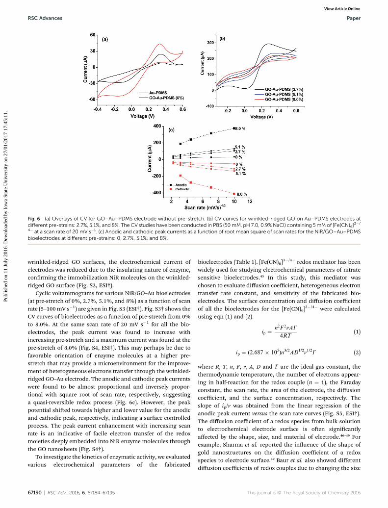
Fig. 6 (a) Overlays of CV for GO–Au–PDMS electrode without pre-stretch. (b) CV curves for wrinkled-ridged GO on Au–PDMS electrodes atdifferent pre-strains: 2.7%, 5.1%, and 8%. The CV studies have been conducted in PBS (50mM, pH 7.0, 0.9%NaCl) containing 5mMof [Fe(CN)6]
3�/
4� at a scan rate of 20 mV s�1. (c) Anodic and cathodic peak currents as a function of root mean square of scan rates for the NiR/GO–Au–PDMSbioelectrodes at different pre-strains: 0, 2.7%, 5.1%, and 8%.
RSC Advances Paper
Publ
ishe
d on
11
July
201
6. D
ownl
oade
d by
Iow
a St
ate
Uni
vers
ity o
n 27
/01/
2017
17:
45:1
1.
View Article Online
wrinkled-ridged GO surfaces, the electrochemical current ofelectrodes was reduced due to the insulating nature of enzyme,conrming the immobilization NiR molecules on the wrinkled-ridged GO surface (Fig. S2, ESI†).
Cyclic voltammograms for various NiR/GO–Au bioelectrodes(at pre-stretch of 0%, 2.7%, 5.1%, and 8%) as a function of scanrate (5–100mV s�1) are given in Fig. S3 (ESI†). Fig. S3† shows theCV curves of bioelectrodes as a function of pre-stretch from 0%to 8.0%. At the same scan rate of 20 mV s�1 for all the bio-electrodes, the peak current was found to increase withincreasing pre-stretch and a maximum current was found at thepre-stretch of 8.0% (Fig. S4, ESI†). This may perhaps be due tofavorable orientation of enzyme molecules at a higher pre-stretch that may provide a microenvironment for the improve-ment of heterogeneous electrons transfer through the wrinkled-ridged GO–Au electrode. The anodic and cathodic peak currentswere found to be almost proportional and inversely propor-tional with square root of scan rate, respectively, suggestinga quasi-reversible redox process (Fig. 6c). However, the peakpotential shied towards higher and lower value for the anodicand cathodic peak, respectively, indicating a surface controlledprocess. The peak current enhancement with increasing scanrate is an indicative of facile electron transfer of the redoxmoieties deeply embedded into NiR enzyme molecules throughthe GO nanosheets (Fig. S4†).
To investigate the kinetics of enzymatic activity, we evaluatedvarious electrochemical parameters of the fabricated
67190 | RSC Adv., 2016, 6, 67184–67195
bioelectrodes (Table 1). [Fe(CN)6]3�/4� redox mediator has been
widely used for studying electrochemical parameters of nitratesensitive bioelectrodes.45 In this study, this mediator waschosen to evaluate diffusion coefficient, heterogeneous electrontransfer rate constant, and sensitivity of the fabricated bio-electrodes. The surface concentration and diffusion coefficientof all the bioelectrodes for the [Fe(CN)6]
3�/4� were calculatedusing eqn (1) and (2).
ip ¼ n2F 2nAG
4RT(1)
ip ¼ (2.687 � 105)n3/2AD1/2n1/2G (2)
where R, T, n, F, n, A, D and G are the ideal gas constant, thethermodynamic temperature, the number of electrons appear-ing in half-reaction for the redox couple (n ¼ 1), the Faradayconstant, the scan rate, the area of the electrode, the diffusioncoefficient, and the surface concentration, respectively. Theslope of ip/n was obtained from the linear regression of theanodic peak current versus the scan rate curves (Fig. S5, ESI†).The diffusion coefficient of a redox species from bulk solutionto electrochemical electrode surface is oen signicantlyaffected by the shape, size, and material of electrode.46–49 Forexample, Sharma et al. reported the inuence of the shape ofgold nanostructures on the diffusion coefficient of a redoxspecies to electrode surface.49 Baur et al. also showed differentdiffusion coefficients of redox couples due to changing the size
This journal is © The Royal Society of Chemistry 2016

Table 1 Comparison of electrochemical parameters for the fabricated tunable NiR/GO–Au bioelectrodes
Pre-stretchratio
Peak current(mA)
Diffusion coefficient(cm2 s�1)
Potential differenceDEp (V)
Surface concentration(mol cm�2)
Heterogeneouselectron transferrate k0 (cm s�1)
Electrochemicalsurface area Ael(cm2 � 10�5)
0% 21.8 1.2 � 10�8 0.56 1.5 � 10�13 0.116 0.152.7% 53.9 8.1 � 10�8 0.12 7.9 � 10�13 0.150 0.225.1% 76 1.5 � 10�7 0.44 9.1 � 10�13 0.200 0.248.0% 239.1 1.6 � 10�6 0.34 2.1 � 10�12 0.237 0.834
Paper RSC Advances
Publ
ishe
d on
11
July
201
6. D
ownl
oade
d by
Iow
a St
ate
Uni
vers
ity o
n 27
/01/
2017
17:
45:1
1.
View Article Online
of disk microelectrodes.50 In addition, the diffusion coefficientsof ferro/ferricyanide were found as 6.9� 10�15 cm2 s�1 and 2.26� 10�10 cm2 s�1 using polyaniline–gold and poly(lactic-co-gly-colic acid) encapsulated iron oxide nanoparticles based elec-trodes, respectively.46,47 In our case, without any wrinkles orridges, the planar NiR/GO–Au bioelectrode shows a low diffu-sion coefficient of 1.2 � 10�8 cm2 s�1 for [Fe(CN)6]
3�/4� speciesfrom bulk solution to electrode surface. As the pre-stretchincreased to 8.0%, the wrinkled-ridged bioelectrode providedmore than two orders of magnitude higher diffusion coefficientto 1.6 � 10�6 cm2 s�1 compared to the planar bioelectrode. Thehigher diffusion coefficient at the pre-stretch of 8.0% may beassociated with higher amplitude of localized ridges and smallwrinkles of this bioelectrode, contributing to radial diffusion ofelectrons. A maximum surface concentration of redox mediator[Fe(CN)6]
3�/4� for the NiR/GO–Au bioelectrode was obtained atthe pre-stretch of 8.0% compared to those obtained under otherpre-stretching conditions (Table 1). Also, in comparison withthe chitosan–TiO2 (ref. 48) and Au nanostructured electrodes,49
the wrinkled-ridged NiR/GO–Au bioelectrodes show a highersurface concentration.
The electrochemical surface area Ael of bioelectrode wasdetermined using eqn (3) described in literature49 and is givenbelow:
Ael ¼ S
ð2:99� 105Þn3=2D1=2G(3)
where S is the slope obtained from the linear regression of ipversus n1/2 as shown in Fig. 6c. Table 1 also shows the calculatedvalues of Ael for the NiR/GO–Au bioelectrodes at different pre-stretch levels and are found to increase with increasing pre-stretch. According to Laviron method, the heterogeneous elec-tron transfer rate constant k0 and the charge-transfer coefficienta of a surface-controlled redox reaction for the fabricated bio-electrodes were calculated using eqn (4)51,52
log k0 ¼ a logð1� aÞ þ ð1� aÞlog aþ log
�RT
nFn
�
� að1� aÞ nFDE
2:303 RT(4)
The k0 values for the NiR/GO–Au electrodes with 2.7%, 5.1%and 8% pre-stretch were found to be higher than that for theplanar bioelectrode (Table 1). The formation of wrinkles-ridges atthe high pre-stretch of 8.0% may presumably allow for favorableorientation of enzyme molecules on its surface to enhance the
This journal is © The Royal Society of Chemistry 2016
electron transfer ability, thus increasing the value of k0. Also, thek0 values for all the fabricated bioelectrodes are found to behigher compared to that using aminated reduced GO.4
3.5. Detection of nitrate ions
We investigated the sensing performance of the fabricated NiR/GO–Au bioelectrodes using CV for detection of nitrate ions(Fig. 7). The nitrate ion concentration was varied from 0 to 1000mM and the scan rate was xed at 20 mV s�1. Fig. 7a shows theCV curves for the bioelectrodes with the pre-stretch of 2.7%. Thepeak current increased with increasing nitrate concentration(see the inset of Fig. 7a). Similarly, for the un-stretched (control)and the other pre-stretched (5.1% and 8%) bioelectrodes, thepeak currents during the detection of nitrate ions increasedwith increasing concentration of nitrate ions (Fig. 7b–d). In thebiochemical reaction (Fig. 1), the NiR enzyme molecules on thesensor surface played an important role for generation of elec-trons. The multiple active sites of the enzymemolecules directlyconverted NO3
� to NO2� via generation of electrons and the
generated electron transferred through the wrinkled GO to theAu layer. More nitrate ions in the electrolyte solution createdmore electrons and the resulting current was directly propor-tional to the concentration of nitrate ions. Thus, other thanmediator electrons from redox reaction, the produced electronsdue to the enzymatic reaction were responsible for enhancingelectrocatalytic current on the sensor surface. The sensingresults (Fig. 7) demonstrate that as the pre-stretch levelincreased, the bioelectrodes became more sensitive to changesin surrounding nitrate ion concentration. Also, compared to theun-stretched planar bioelectrode, the pre-stretched bio-electrodes provide a wider concentration range of ion detection(Fig. S6, ESI†). Table 2 summarizes the sensing performances ofall the fabricated bioelectrodes and their comparison with thosereported in literature. The comparison indicates that the wrin-kled and wrinkled-ridged bioelectrodes offer higher sensitivitiescompared to those using carbon nanotubes–polypyrrole nano-composite,7 polypyrrole,8 platinum–tin,9 silver particle–poly-methacrylic acid,10 and 1-methyl-3-(pyrrol-1-yl-methyl)pyridinium4 for electrochemical nitrate detection.
Fig. 8a shows the schematic of the planar and wrinkled-ridged GO with diffusion of generated electrons via redoxreaction. The planar bioelectrode (0% pre-stretch) is consideredwith linear diffusion of ions from the bulk solution, providingrelatively low diffusivity and sensitivity in the response (Fig. 8b).The wrinkled bioelectrode with the pre-stretch of 2.7% provided
RSC Adv., 2016, 6, 67184–67195 | 67191
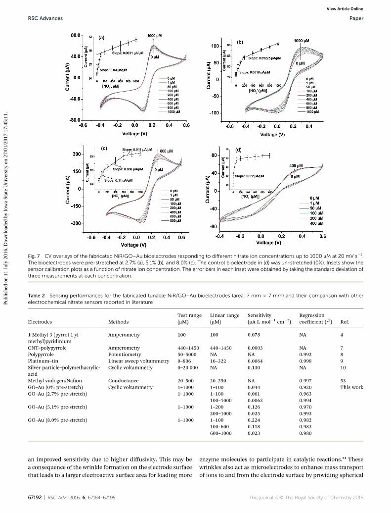
Fig. 7 CV overlays of the fabricated NiR/GO–Au bioelectrodes responding to different nitrate ion concentrations up to 1000 mM at 20 mV s�1.The bioelectrodes were pre-stretched at 2.7% (a), 5.1% (b), and 8.0% (c). The control bioelectrode in (d) was un-stretched (0%). Insets show thesensor calibration plots as a function of nitrate ion concentration. The error bars in each inset were obtained by taking the standard deviation ofthree measurements at each concentration.
Table 2 Sensing performances for the fabricated tunable NiR/GO–Au bioelectrodes (area: 7 mm � 7 mm) and their comparison with otherelectrochemical nitrate sensors reported in literature
Electrodes MethodsTest range(mM)
Linear range(mM)
Sensitivity(mA L mol�1 cm�2)
Regressioncoefficient (r2) Ref.
1-Methyl-3-(pyrrol-1-yl-methyl)pyridinium
Amperometry 100 100 0.078 NA 4
CNT–polypyrrole Amperometry 440–1450 440–1450 0.0003 NA 7Polypyrrole Potentiometry 50–5000 NA NA 0.992 8Platinum–tin Linear sweep voltammetry 0–806 16–322 0.0064 0.998 9Silver particle–polymethacrylic-acid
Cyclic voltammetry 0–20 000 NA 0.130 NA 10
Methyl viologen/Naon Conductance 20–500 20–250 NA 0.997 53GO–Au (0% pre-stretch) Cyclic voltammetry 1–1000 1–100 0.044 0.920 This workGO–Au (2.7% pre-stretch) 1–1000 1–100 0.061 0.963
100–1000 0.0063 0.994GO–Au (5.1% pre-stretch) 1–1000 1–200 0.126 0.970
200–1000 0.025 0.993GO–Au (8.0% pre-stretch) 1–1000 1–100 0.224 0.982
100–600 0.118 0.983600–1000 0.023 0.980
RSC Advances Paper
Publ
ishe
d on
11
July
201
6. D
ownl
oade
d by
Iow
a St
ate
Uni
vers
ity o
n 27
/01/
2017
17:
45:1
1.
View Article Online
an improved sensitivity due to higher diffusivity. This may bea consequence of the wrinkle formation on the electrode surfacethat leads to a larger electroactive surface area for loading more
67192 | RSC Adv., 2016, 6, 67184–67195
enzyme molecules to participate in catalytic reactions.54 Thesewrinkles also act as microelectrodes to enhance mass transportof ions to and from the electrode surface by providing spherical
This journal is © The Royal Society of Chemistry 2016
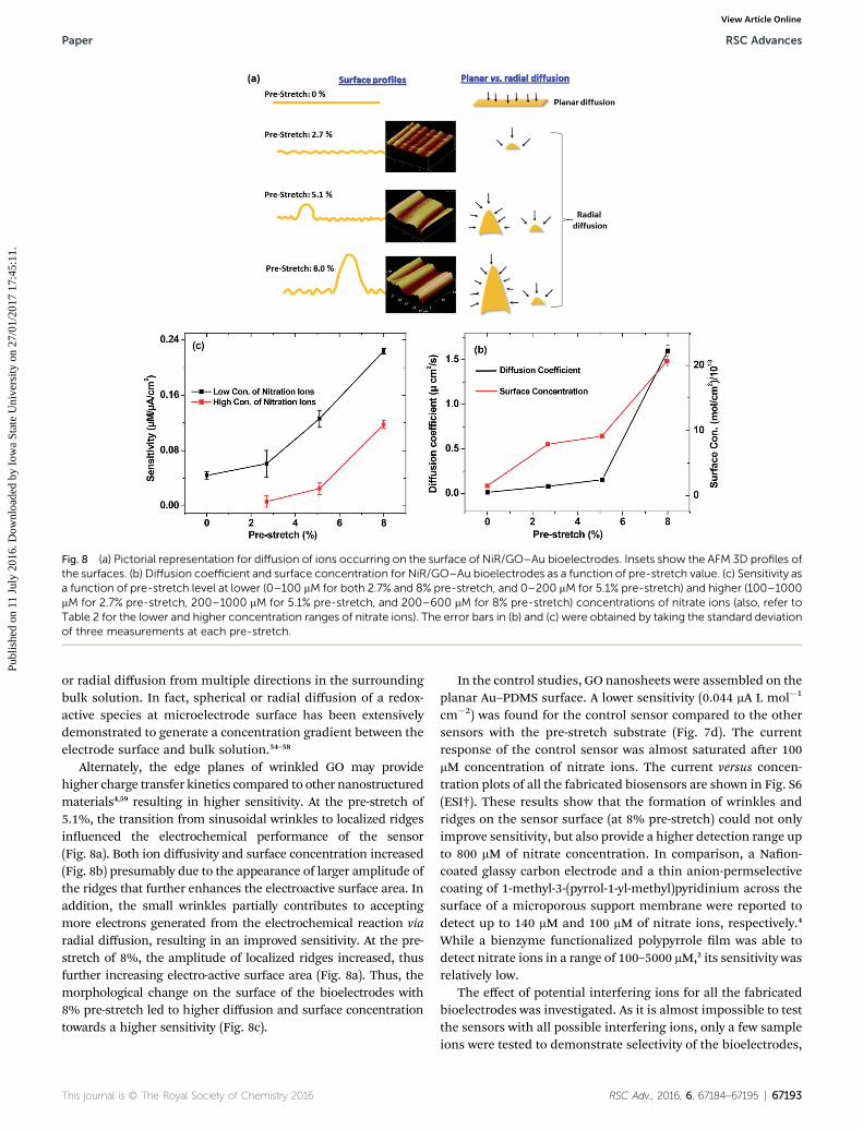
Fig. 8 (a) Pictorial representation for diffusion of ions occurring on the surface of NiR/GO–Au bioelectrodes. Insets show the AFM 3D profiles ofthe surfaces. (b) Diffusion coefficient and surface concentration for NiR/GO–Au bioelectrodes as a function of pre-stretch value. (c) Sensitivity asa function of pre-stretch level at lower (0–100 mM for both 2.7% and 8% pre-stretch, and 0–200 mM for 5.1% pre-stretch) and higher (100–1000mM for 2.7% pre-stretch, 200–1000 mM for 5.1% pre-stretch, and 200–600 mM for 8% pre-stretch) concentrations of nitrate ions (also, refer toTable 2 for the lower and higher concentration ranges of nitrate ions). The error bars in (b) and (c) were obtained by taking the standard deviationof three measurements at each pre-stretch.
Paper RSC Advances
Publ
ishe
d on
11
July
201
6. D
ownl
oade
d by
Iow
a St
ate
Uni
vers
ity o
n 27
/01/
2017
17:
45:1
1.
View Article Online
or radial diffusion from multiple directions in the surroundingbulk solution. In fact, spherical or radial diffusion of a redox-active species at microelectrode surface has been extensivelydemonstrated to generate a concentration gradient between theelectrode surface and bulk solution.54–58
Alternately, the edge planes of wrinkled GO may providehigher charge transfer kinetics compared to other nanostructuredmaterials4,59 resulting in higher sensitivity. At the pre-stretch of5.1%, the transition from sinusoidal wrinkles to localized ridgesinuenced the electrochemical performance of the sensor(Fig. 8a). Both ion diffusivity and surface concentration increased(Fig. 8b) presumably due to the appearance of larger amplitude ofthe ridges that further enhances the electroactive surface area. Inaddition, the small wrinkles partially contributes to acceptingmore electrons generated from the electrochemical reaction viaradial diffusion, resulting in an improved sensitivity. At the pre-stretch of 8%, the amplitude of localized ridges increased, thusfurther increasing electro-active surface area (Fig. 8a). Thus, themorphological change on the surface of the bioelectrodes with8% pre-stretch led to higher diffusion and surface concentrationtowards a higher sensitivity (Fig. 8c).
This journal is © The Royal Society of Chemistry 2016
In the control studies, GO nanosheets were assembled on theplanar Au–PDMS surface. A lower sensitivity (0.044 mA L mol�1
cm�2) was found for the control sensor compared to the othersensors with the pre-stretch substrate (Fig. 7d). The currentresponse of the control sensor was almost saturated aer 100mM concentration of nitrate ions. The current versus concen-tration plots of all the fabricated biosensors are shown in Fig. S6(ESI†). These results show that the formation of wrinkles andridges on the sensor surface (at 8% pre-stretch) could not onlyimprove sensitivity, but also provide a higher detection range upto 800 mM of nitrate concentration. In comparison, a Naon-coated glassy carbon electrode and a thin anion-permselectivecoating of 1-methyl-3-(pyrrol-1-yl-methyl)pyridinium across thesurface of a microporous support membrane were reported todetect up to 140 mM and 100 mM of nitrate ions, respectively.4
While a bienzyme functionalized polypyrrole lm was able todetect nitrate ions in a range of 100–5000 mM,2 its sensitivity wasrelatively low.
The effect of potential interfering ions for all the fabricatedbioelectrodes was investigated. As it is almost impossible to testthe sensors with all possible interfering ions, only a few sampleions were tested to demonstrate selectivity of the bioelectrodes,
RSC Adv., 2016, 6, 67184–67195 | 67193
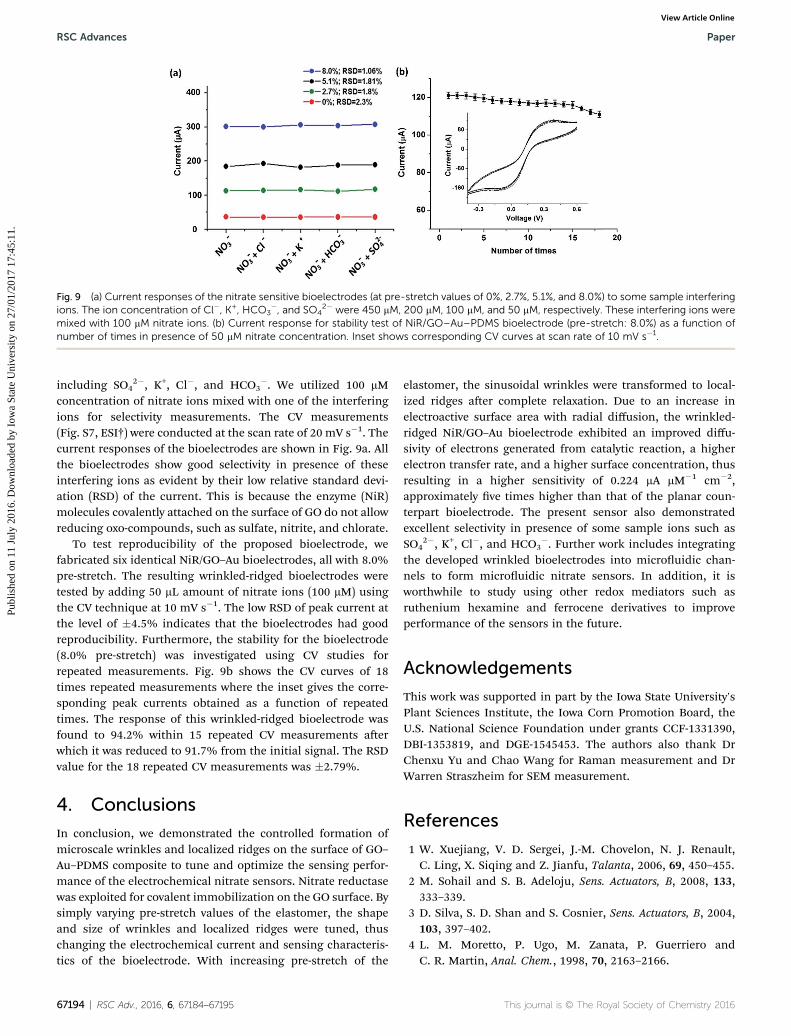
Fig. 9 (a) Current responses of the nitrate sensitive bioelectrodes (at pre-stretch values of 0%, 2.7%, 5.1%, and 8.0%) to some sample interferingions. The ion concentration of Cl�, K+, HCO3
�, and SO42� were 450 mM, 200 mM, 100 mM, and 50 mM, respectively. These interfering ions were
mixed with 100 mM nitrate ions. (b) Current response for stability test of NiR/GO–Au–PDMS bioelectrode (pre-stretch: 8.0%) as a function ofnumber of times in presence of 50 mM nitrate concentration. Inset shows corresponding CV curves at scan rate of 10 mV s�1.
RSC Advances Paper
Publ
ishe
d on
11
July
201
6. D
ownl
oade
d by
Iow
a St
ate
Uni
vers
ity o
n 27
/01/
2017
17:
45:1
1.
View Article Online
including SO42�, K+, Cl�, and HCO3
�. We utilized 100 mMconcentration of nitrate ions mixed with one of the interferingions for selectivity measurements. The CV measurements(Fig. S7, ESI†) were conducted at the scan rate of 20 mV s�1. Thecurrent responses of the bioelectrodes are shown in Fig. 9a. Allthe bioelectrodes show good selectivity in presence of theseinterfering ions as evident by their low relative standard devi-ation (RSD) of the current. This is because the enzyme (NiR)molecules covalently attached on the surface of GO do not allowreducing oxo-compounds, such as sulfate, nitrite, and chlorate.
To test reproducibility of the proposed bioelectrode, wefabricated six identical NiR/GO–Au bioelectrodes, all with 8.0%pre-stretch. The resulting wrinkled-ridged bioelectrodes weretested by adding 50 mL amount of nitrate ions (100 mM) usingthe CV technique at 10 mV s�1. The low RSD of peak current atthe level of �4.5% indicates that the bioelectrodes had goodreproducibility. Furthermore, the stability for the bioelectrode(8.0% pre-stretch) was investigated using CV studies forrepeated measurements. Fig. 9b shows the CV curves of 18times repeated measurements where the inset gives the corre-sponding peak currents obtained as a function of repeatedtimes. The response of this wrinkled-ridged bioelectrode wasfound to 94.2% within 15 repeated CV measurements aerwhich it was reduced to 91.7% from the initial signal. The RSDvalue for the 18 repeated CV measurements was �2.79%.
4. Conclusions
In conclusion, we demonstrated the controlled formation ofmicroscale wrinkles and localized ridges on the surface of GO–Au–PDMS composite to tune and optimize the sensing perfor-mance of the electrochemical nitrate sensors. Nitrate reductasewas exploited for covalent immobilization on the GO surface. Bysimply varying pre-stretch values of the elastomer, the shapeand size of wrinkles and localized ridges were tuned, thuschanging the electrochemical current and sensing characteris-tics of the bioelectrode. With increasing pre-stretch of the
67194 | RSC Adv., 2016, 6, 67184–67195
elastomer, the sinusoidal wrinkles were transformed to local-ized ridges aer complete relaxation. Due to an increase inelectroactive surface area with radial diffusion, the wrinkled-ridged NiR/GO–Au bioelectrode exhibited an improved diffu-sivity of electrons generated from catalytic reaction, a higherelectron transfer rate, and a higher surface concentration, thusresulting in a higher sensitivity of 0.224 mA mM�1 cm�2,approximately ve times higher than that of the planar coun-terpart bioelectrode. The present sensor also demonstratedexcellent selectivity in presence of some sample ions such asSO4
2�, K+, Cl�, and HCO3�. Further work includes integrating
the developed wrinkled bioelectrodes into microuidic chan-nels to form microuidic nitrate sensors. In addition, it isworthwhile to study using other redox mediators such asruthenium hexamine and ferrocene derivatives to improveperformance of the sensors in the future.
Acknowledgements
This work was supported in part by the Iowa State University'sPlant Sciences Institute, the Iowa Corn Promotion Board, theU.S. National Science Foundation under grants CCF-1331390,DBI-1353819, and DGE-1545453. The authors also thank DrChenxu Yu and Chao Wang for Raman measurement and DrWarren Straszheim for SEM measurement.
References
1 W. Xuejiang, V. D. Sergei, J.-M. Chovelon, N. J. Renault,C. Ling, X. Siqing and Z. Jianfu, Talanta, 2006, 69, 450–455.
2 M. Sohail and S. B. Adeloju, Sens. Actuators, B, 2008, 133,333–339.
3 D. Silva, S. D. Shan and S. Cosnier, Sens. Actuators, B, 2004,103, 397–402.
4 L. M. Moretto, P. Ugo, M. Zanata, P. Guerriero andC. R. Martin, Anal. Chem., 1998, 70, 2163–2166.
This journal is © The Royal Society of Chemistry 2016
Paper RSC Advances
Publ
ishe
d on
11
July
201
6. D
ownl
oade
d by
Iow
a St
ate
Uni
vers
ity o
n 27
/01/
2017
17:
45:1
1.
View Article Online
5 N. Adarsh, M. Shanmugasundaram and D. Ramaiah, Anal.Chem., 2013, 85, 10008–10012.
6 W. L. Daniel, M. S. Han, J.-S. Lee and C. A. Mirkin, J. Am.Chem. Soc., 2009, 131, 6362–6363.
7 F. Can, S. K. Ozoner, P. Ergenekon and E. Erhan, Mater. Sci.Eng., C, 2012, 32, 18.
8 M. Sohail and S. B. Adeloju, Electroanalysis, 2009, 21, 1411–1418.
9 Y. Fu, C. Bian, J. Kuang, J. Wang, J. Tong and S. A. Xia,Sensors, 2015, 15, 23249.
10 S. G. Leonardi, N. Donato, A. Bonavita, G. Neri, M. Bonyaniand A. Mirzaei, IEEE InAISEM Ann. Conf., 2015, pp. 1–4.
11 K. Kostarelos and K. S. Novoselov, Nat. Nanotechnol., 2014, 9,274.
12 Z. Tehrani, G. Burwell, M. A. M. Azmi, A. Castaing,R. Rickman, J. Almarashi, P. Dunstan, A. M. Beigi,S. H. Doak and O. J. Guy, 2D Materials, 2014, 1, 025004.
13 W. Park, J. M. Yoon, M. Park, J. Lee, S. K. Kim, J. W. Jeong,K. Kim, H. Y. Jeong, S. Jeon, K. S. No, J. Y. Lee andY. S. Jung, Nano Lett., 2012, 12, 1235–1240.
14 C. Gomez-Navarro, R. T. Weitz, A. M. Bittner, M. Scolari,A. Mews, M. Burghard and K. Kern, Nano Lett., 2007, 7,3499–3503.
15 F. Bonaccorso, Z. Sun, T. Hasan and A. C. Ferrari, Nat.Photonics, 2010, 4, 611–622.
16 J. T. Robinson, F. K. Perkins, E. S. Snow, Z. Wei andP. E. Sheehan, Nano Lett., 2008, 8, 3137–3140.
17 H. Gwon, H.-S. Kim, K. U. Lee, D.-H. Seo, Y. C. Park, Y.-S. Lee,B. T. Ahn and K. Kisuk, Energy Environ. Sci., 2011, 4, 1277–1283.
18 D. R. Dreyer, S. Park, C. W. Bielawski and R. S. Ruoff, Chem.Soc. Rev., 2010, 39, 228–240.
19 Y. Zhu, S. Murali, W. Cai, X. Li, J. W. Suk, J. R. Potts andR. S. Ruoff, Adv. Mater., 2010, 22, 3906–3924.
20 Z. Wen, X. Wang, S. Mao, Z. Bo, H. Kim, S. Cui and J. Chen, J.Adv. Mater., 2012, 24, 5610–5616.
21 M. F. El-Kady, V. Strong, S. Dubin and R. B. Kaner, Science,2012, 335, 1326–1330.
22 J. H. Jung, D. S. Cheon, F. Liu, K. B. Lee and T. S. Seo, Angew.Chem., Int. Ed. Engl., 2010, 49, 5708–5711.
23 P. Zhang, X. Chai, C. Xu and J. Zhou, IEEE 9th Internation.Conf., ASIC (ASICON), 2011, pp. 653–656.
24 H. A. Becerril, J. Mao, Z. Liu, R. M. Stoltenberg, Z. Bao andY. Chen, ACS Nano, 2008, 2, 463–470.
25 O. C. Compton and S. T. Nguyen, Small, 2010, 6, 711–723.26 T. Chen, Y. Xue, A. K. Roy and L. Dai, ACS Nano, 2013, 8,
1039–1046.27 B. G. Choi, H. Park, T. J. Park, M. H. Yang, J. S. Kim,
S. Y. Jang, N. S. Heo, S. Y. Lee, J. Kong and W. H. Hong,ACS Nano, 2010, 4, 2910–2918.
28 V. Mani, A. P. Periasamy and S.-M. Chen, Electrochem.Commun., 2012, 17, 75–78.
29 L. Tang, H. Feng, J. Cheng and J. Li, Chem. Commun., 2010,46, 5882–5884.
30 N. G. Shang, P. Papakonstantinou, M. McMullan, M. Chu,A. Stamboulis, A. Potenza, S. S. Dhesi and H. Marchetto,Adv. Funct. Mater., 2008, 18, 3506–3514.
This journal is © The Royal Society of Chemistry 2016
31 S. H. Ahn and L. J. Guo, Nano Lett., 2010, 10, 4228–4234.32 T. Ohzono, H. Watanabe, R. Vendamme, C. Kamaga,
T. Kunitake, T. Ishihara and M. Shimomura, Adv. Mater.,2007, 19, 3229–3232.
33 J. Zang, X. Zhao, Y. Cao and J. W. Hutchinson, J. Mech. Phys.Solids., 2012, 60, 1265–1279.
34 L. Jin, A. Takei and J. W. Hutchinson, J. Mech. Phys. Solids,2015, 81, 22–40.
35 J. Y. Chung, A. J. Nolte and C. M. Stafford, Adv. Mater., 2011,23, 349–368.
36 K. Emenko, M. Rackaitis, E. Manias, A. Vaziri,L. Mahadevan and J. Genzer, Nat. Mater., 2005, 4, 293–297.
37 J. A. Rogers, T. Someya and Y. Huang, Science, 2010, 327,1603–1607.
38 T. Ma, H. Liang, G. Chen, B. Poon, H. Jiang and H. Yu, Opt.Express, 2013, 21, 11994–12001.
39 C. Cao, H. F. Chan, J. Zang, K. W. Leong and X. Zhao, Adv.Mater., 2014, 26, 1763–1770.
40 L. Pocivavsek, R. Dellsy, A. Kern, S. Johnson, B. Lin,K. Y. C. Lee and E. Cerda, Science, 2008, 320, 912–916.
41 Q. Wang and X. Zhao, Sci. Rep., 2015, 5, 8887.42 O. Akhavan and E. Ghaderia, Carbon, 2012, 50, 1853–1860.43 S. Pei and H.-M. Cheng, Carbon, 2012, 50, 3210–3228.44 M. Acik, G. Lee, C. Mattevi, A. Pirkle, R. M. Wallace,
M. Chhowalla and Y. Chabal, J. Phys. Chem. C, 2011, 115,19761–19781.
45 B. Strehlitz, B. Grundig, W. Schumacher, P. M. Kroneck,K. D. Vorlop and H. Kotte, Anal. Chem., 1996, 68, 807–816.
46 A. Soni, C. M. Pandey, S. Solanki and G. Sumana, RSC Adv.,2015, 5, 45767–45774.
47 C. M. Pandey, I. Tiwari and G. Sumana, RSC Adv., 2014, 4,31047–31055.
48 M. A. Ali, S. Srivastava, K. Mondal, P. M. Chavhan,V. V. Agrawal, R. John, A. Sharma and B. D. Malhotra,Nanoscale, 2014, 6, 13958–13969.
49 S. Rachna, V. V. Agrawal, A. K. Srivastava, L. Nain, M. Imran,S. R. Kabi, R. K. Sinha and B. D. Malhotra, J. Mater. Chem. B,2013, 1, 464–474.
50 J. E. Baur and R. M. Wightman, J. Electroanal. Chem.Interfacial Electrochem., 1991, 305, 73–81.
51 A. L. Eckermann, D. J. Feld, J. A. Shaw and T. J. Meade,Coord. Chem. Rev., 2010, 54, 1769–1802.
52 M. A. Ali, K. K. Reza, S. Srivastava, V. V. Agrawal, R. John andB. D. Malhotra, Langmuir, 2014, 30, 4192–4201.
53 X. Wang, S. V. Dzyadevych, J. M. Chovelon, N. J. Renault,L. Chen, S. Xia and J. Zhao, Electrochem. Commun., 2006, 8,201–205.
54 N. Godino, X. Borrise, F. X. Munoz, F. J. del Campo andR. G. Compton, J. Phys. Chem. C, 2009, 113, 11119–11125.
55 R. J. Forster, Chem. Soc. Rev., 1994, 23, 289–297.56 J. Heinze, Angew. Chem., Int. Ed., 1991, 30, 170–171.57 M. Pumera, Nanomaterials for Electrochemical Sensing and
Biosensing, CRC Press, 2014.58 T. J. Davies and R. G. Compton, J. Electroanal. Chem., 2005,
585, 63–82.59 S. A. Glazier, E. R. Campbell and W. H. Campbell, Anal.
Chem., 1998, 70, 1511–1515.
RSC Adv., 2016, 6, 67184–67195 | 67195