Newsletter 5 - CST · PDF fileNewsletter 5.5 . Antenna Magus Version 5.5 released! Quad...
5
Version 5.5 sees a number of extensions to Antenna Magus features as well as the addition of new transitions and antennas. Though there are too many new additions to discuss in this newsletter, we will briefly highlight some of the feature extensions and new designs that have been made available. More information on these can be found on the Antenna Magus website and in the full release notes. October 2015 Newsletter 5.5 Explore.Design.Deliver. Antenna Magus Version 5.5 released! Quad ridged conical horn and Coaxial to quad-ridged waveguide transition The quad-ridged horn or quadruple-ridge flared horn (QRFH) has two important characteristics: (1) an almost-constant nominal 10 dB beamwidth over a 5:1 frequency band for a design range between 50° and 140° (2) the dual-feeds can be excited to realise various polarisations and the input impedance of each port can be independantly designed between 50 Ω and 100 Ω. This horn is popular in weight and cost-sensitive applications where multi-polarisation capable antennas are used, as only one single-ended low-noise amplifier (LNA) is required per polarisation. In addition to the following new antennas, a diverse set of new transitions have also been added. The new designs are: New Antennas and Transitions New Features The Chart Tracer tool is used to help Antenna Magus Users trace plots from measurements or papers and convert them into digitized traces. In addition to tracing the data, relevant type-specific properties of the traced data are calculated. These derived values can be used to quickly populate value-based specifications for design in the Specification library. In the Version 5.5 update of Antenna Magus, the Chart Tracer tool has been converted to use a ribbon menu interface. An intelligent locking mechanism has been added to allow the overlay and tracing of charts with different aspect ratios and axis ranges and types. A number of new derived quantity types have also been added. The Chart Tracing tool with a ribbon menu interface and new secondary side-lobe derived quantities shown The usage of the Not button in Find Mode to exclude templates that do not have as specific keyword Besides the improvement and updating of many export models to support the latest capabilities available in the simulation tools supported by Antenna Magus, a number of small feature extensions have been added. In Find Mode, a button has been added to the active keywords making it possible to find templates that do not match that specific keyword. In the image on the left, for example, a search for Medium gain antennas that are not Horns, Patches or Arrays is now possible. Antennas: • Quad-ridged wide-band conical horn antenna • 2 x 2 array of wire helix antennas • Cylindrical Luneberg lens (with pyramidal horn feed) Transitions: • Microstrip to waveguide transition • Microstrip quadrature hybrid coupler • Microstrip ‘rat race’ coupler • Microstrip radial stub band-stop filter The updated Chart Tracer Find Mode • Spherical Luneberg lens (with pyramidal horn feed) • Planar elliptical dipole antenna • Coax to circular waveguide transition • Coax to microstrip line transition • Coax to quad-ridged waveguide transition • Coax to coplanar waveguide (CPW) transition Total circular gain 3D patterns of the QRFH at (a) 0.5 x f0, (b) f0, and (c) 1.5 x f0
Transcript of Newsletter 5 - CST · PDF fileNewsletter 5.5 . Antenna Magus Version 5.5 released! Quad...
Version 5.5 sees a number of extensions to Antenna Magus features as well as the addition of new transitions and antennas. Though there are too many new additions to discuss in this newsletter, we will briefly highlight some of the feature extensions and new designs that have been made available. More information on these can be found on the Antenna Magus website and in the full release notes.
October 2015Newsletter 5.5
Explore.Design.Deliver.
Antenna Magus Version 5.5 released!
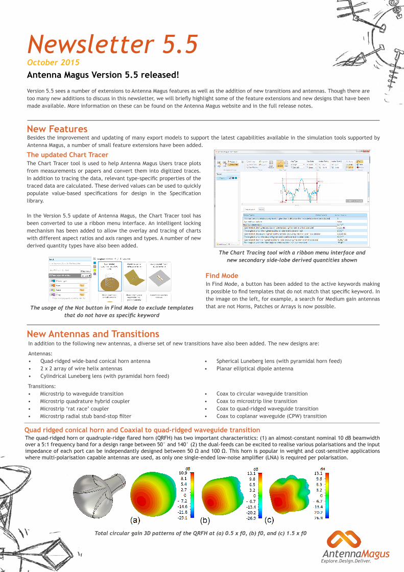
Quad ridged conical horn and Coaxial to quad-ridged waveguide transitionThe quad-ridged horn or quadruple-ridge flared horn (QRFH) has two important characteristics: (1) an almost-constant nominal 10 dB beamwidth over a 5:1 frequency band for a design range between 50° and 140° (2) the dual-feeds can be excited to realise various polarisations and the input impedance of each port can be independantly designed between 50 Ω and 100 Ω. This horn is popular in weight and cost-sensitive applications where multi-polarisation capable antennas are used, as only one single-ended low-noise amplifier (LNA) is required per polarisation.
The radiation pattern of an 8 element linear patch array with a corporate feed network
In addition to the following new antennas, a diverse set of new transitions have also been added. The new designs are:New Antennas and Transitions
New Features
The Chart Tracer tool is used to help Antenna Magus Users trace plots from measurements or papers and convert them into digitized traces. In addition to tracing the data, relevant type-specific properties of the traced data are calculated. These derived values can be used to quickly populate value-based specifications for design in the Specification library.
In the Version 5.5 update of Antenna Magus, the Chart Tracer tool has been converted to use a ribbon menu interface. An intelligent locking mechanism has been added to allow the overlay and tracing of charts with different aspect ratios and axis ranges and types. A number of new derived quantity types have also been added.
The Chart Tracing tool with a ribbon menu interface and new secondary side-lobe derived quantities shown
The usage of the Not button in Find Mode to exclude templates that do not have as specific keyword
Besides the improvement and updating of many export models to support the latest capabilities available in the simulation tools supported by Antenna Magus, a number of small feature extensions have been added.
In Find Mode, a button has been added to the active keywords making it possible to find templates that do not match that specific keyword. In the image on the left, for example, a search for Medium gain antennas that are not Horns, Patches or Arrays is now possible.
Antennas:• Quad-ridged wide-band conical horn antenna• 2 x 2 array of wire helix antennas• Cylindrical Luneberg lens (with pyramidal horn feed)
Transitions:• Microstrip to waveguide transition• Microstrip quadrature hybrid coupler• Microstrip ‘rat race’ coupler• Microstrip radial stub band-stop filter
The updated Chart Tracer
Find Mode
• Spherical Luneberg lens (with pyramidal horn feed)• Planar elliptical dipole antenna
• Coax to circular waveguide transition• Coax to microstrip line transition• Coax to quad-ridged waveguide transition• Coax to coplanar waveguide (CPW) transition
Total circular gain 3D patterns of the QRFH at (a) 0.5 x f0, (b) f0, and (c) 1.5 x f0
Explore.Design.Deliver.
Horn-fed spherical and cylindrical Luneburg lenses
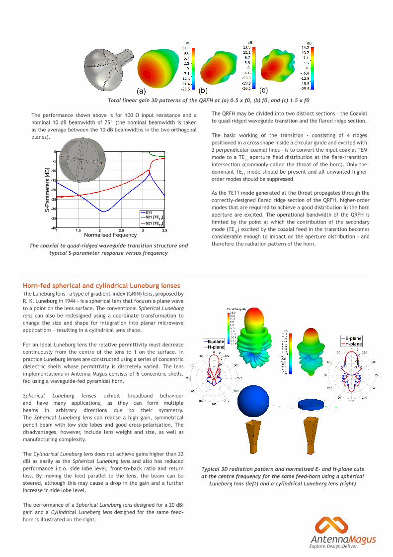
The coaxial to quad-ridged waveguide transition structure and typical S-parameter response versus frequency
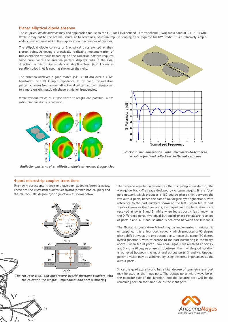
The Luneburg lens - a type of gradient-index (GRIN) lens, proposed by R. K. Luneburg in 1944 - is a spherical lens that focuses a plane wave to a point on the lens surface. The conventional Spherical Luneburg lens can also be redesigned using a coordinate transformation to change the size and shape for integration into planar microwave applications – resulting in a cylindrical lens shape.
For an ideal Luneburg lens the relative permittivity must decrease continuously from the centre of the lens to 1 on the surface. In practice Luneburg lenses are constructed using a series of concentric dielectric shells whose permittivity is discretely varied. The lens implementations in Antenna Magus consists of 6 concentric shells, fed using a waveguide-fed pyramidal horn.
Spherical Luneburg lenses exhibit broadband behaviour and have many applications, as they can form multiple beams in arbitrary directions due to their symmetry. The Spherical Luneberg lens can realise a high gain, symmetrical pencil beam with low side lobes and good cross-polarisation. The disadvantages, however, include lens weight and size, as well as manufacturing complexity.
The Cylindrical Luneburg lens does not achieve gains higher than 22 dBi as easily as the Spherical Luneburg lens and also has reduced performance i.t.o. side lobe level, front-to-back ratio and return loss. By moving the feed parallel to the lens, the beam can be steered, although this may cause a drop in the gain and a further increase in side lobe level.
The performance of a Spherical Luneberg lens designed for a 20 dBi gain and a Cylindrical Luneberg lens designed for the same feed-horn is illustrated on the right.
The QRFH may be divided into two distinct sections – the Coaxial to quad-ridged waveguide transition and the flared ridge section.
The basic working of the transition - consisting of 4 ridges positioned in a cross shape inside a circular guide and excited with 2 perpendicular coaxial lines - is to convert the input coaxial TEM mode to a TE11 aperture field distribution at the flare-transition intersection (commonly called the throat of the horn). Only the dominant TE11 mode should be present and all unwanted higher order modes should be suppressed.
The performance shown above is for 100 Ω input resistance and a nominal 10 dB beamwidth of 75° (the nominal beamwidth is taken as the average between the 10 dB beamwidths in the two orthogonal planes).
Typical 3D radiation pattern and normalised E- and H-plane cuts at the centre frequency for the same feed-horn using a spherical
Luneberg lens (left) and a cylindrical Luneberg lens (right)
As the TE11 mode generated at the throat propagates through the correctly-designed flared ridge section of the QRFH, higher-order modes that are required to achieve a good distribution in the horn aperture are excited. The operational bandwidth of the QRFH is limited by the point at which the contribution of the secondary mode (TE12) excited by the coaxial feed in the transition becomes considerable enough to impact on the aperture distribution – and therefore the radiation pattern of the horn.
1 1.5 2 2.5 3 3.5-40
-35
-30
-25
-20
-15
-10
-5
0
Normalised frequency
S-P
aram
eter
s [d
B]
S11S21 [TE11]S21 [TE12]
Total linear gain 3D patterns of the QRFH at (a) 0.5 x f0, (b) f0, and (c) 1.5 x f0
Explore.Design.Deliver.
The elliptical dipole consists of 2 elliptical discs excited at their closest point. Achieving a practically realizable implementation of this excitation without impacting on the radiation pattern requires some care. Since the antenna pattern displays nulls in the axial direction, a microstrip-to-balanced stripline feed (also known as parallel strips line) is used, as shown on the right.
The antenna achieves a good match (S11 < -10 dB) over a > 6:1 bandwidth for a 100 Ω input impedance. In this band, the radiation pattern changes from an omnidirectional pattern at low frequencies, to a more erratic multipath shape at higher frequencies.
While various ratios of ellipse width-to-length are possible, a 1:1 ratio (circular discs) is common.
Planar elliptical dipole antenna
Practical implementation with microstrip-to-balanced stripline feed and reflection coefficient response
1 2 3 4 5 6 7 8 9 10-40
-35
-30
-25
-20
-15
-10
-5
0
Normalised Frequency
S-P
aram
eter
s [d
B]
Radiation patterns of an elliptical dipole at various frequencies
Two new 4-port coupler transitions have been added to Antenna Magus. These are the Microstrip quadrature hybrid (branch-line coupler) and the rat-race (180 degree hybrid junction) as shown below.
4-port microstrip coupler transitions
The rat-race (top) and quadrature hybrid (bottom) couplers with the relevant line lengths, impedances and port numbering
The rat-race may be considered as the microstrip equivalent of the waveguide Magic-T already designed by Antenna Magus. It is a four-port network which produces a 180 degree phase shift between the two output ports, hence the name “180 degree hybrid junction”. With reference to the port numbers shown on the left - when fed at port 1 (also known as the Sum port), two equal and in-phase signals are received at ports 2 and 3; while when fed at port 4 (also known as the Difference port), two equal but out-of-phase signals are received at ports 2 and 3. Good isolation is achieved between the two input
The Microstrip quadrature hybrid may be implemented in microstrip or stripline. It is a four-port network which produces a 90 degree phase shift between the two output ports, hence the name “90 degree hybrid junction”. With reference to the port numbering in the image above - when fed at port 1, two equal signals are received at ports 2 and 3 with a 90 degree phase shift between them; while good isolation is achieved between the input and output ports (1 and 4). Unequal power division may be achieved by using different impedances at the output ports.
Since the quadrature hybrid has a high degree of symmetry, any port may be used as the input port. The output ports will always be on the opposite side of the junction, and the isolated port will be the remaining port on the same side as the input port.
The elliptical dipole antenna may find application for use in the FCC (or ETSI) defined ultra-wideband (UWB) radio band of 3.1 – 10.6 GHz. While it may not be the optimal structure to serve as a Gaussian impulse shaping filter required for UWB radio, it is a relatively simple, widely used antenna which finds application in a number of devices.
Explore.Design.Deliver.
Transitions from Coaxial line to planar transmission line realisations
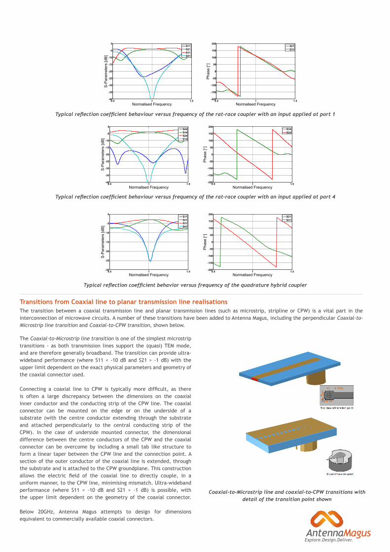
The Coaxial-to-Microstrip line transition is one of the simplest microstrip transitions - as both transmission lines support the (quasi) TEM mode, and are therefore generally broadband. The transition can provide ultra-wideband performance (where S11 < -10 dB and S21 > -1 dB) with the upper limit dependent on the exact physical parameters and geometry of the coaxial connector used.
Connecting a coaxial line to CPW is typically more difficult, as there is often a large discrepancy between the dimensions on the coaxial inner conductor and the conducting strip of the CPW line. The coaxial connector can be mounted on the edge or on the underside of a substrate (with the centre conductor extending through the substrate and attached perpendicularly to the central conducting strip of the CPW). In the case of underside mounted connector, the dimensional difference between the centre conductors of the CPW and the coaxial connector can be overcome by including a small tab like structure to form a linear taper between the CPW line and the connection point. A section of the outer conductor of the coaxial line is extended, through the substrate and is attached to the CPW groundplane. This construction allows the electric field of the coaxial line to directly couple, in a uniform manner, to the CPW line, minimising mismatch. Ultra-wideband performance (where S11 < -10 dB and S21 > -1 dB) is possible, with the upper limit dependent on the geometry of the coaxial connector.
Below 20GHz, Antenna Magus attempts to design for dimensions equivalent to commercially available coaxial connectors.
Coaxial-to-Microstrip line and coaxial-to-CPW transitions with detail of the transition point shown
Typical reflection coefficient behaviour versus frequency of the rat-race coupler with an input applied at port 1
0.5 1 1.5-40
-35
-30
-25
-20
-15
-10
-5
0
Normalised FrequencyS
-Par
amet
ers
[dB
]
S11S21S31S41
0.5 1 1.5-200
-150
-100
-50
0
50
100
150
200
Normalised Frequency
Pha
se [ °
]
S21S31
Typical reflection coefficient behaviour versus frequency of the rat-race coupler with an input applied at port 4
0.5 1 1.5-40
-35
-30
-25
-20
-15
-10
-5
0
Normalised Frequency
S-P
aram
eter
s [d
B]
S44S34S24S14
0.5 1 1.5-200
-150
-100
-50
0
50
100
150
200
Normalised Frequency
Pha
se [ °
]
S34S24
Typical reflection coefficient behavior versus frequency of the quadrature hybrid coupler
0.5 1 1.5-30
-25
-20
-15
-10
-5
0
Normalised Frequency
S-P
aram
eter
s [d
B]
S11S21S31S41
0.5 1 1.5-200
-150
-100
-50
0
50
100
150
200
Normalised Frequency
Pha
se [ °
]
S21S31
The transition between a coaxial transmission line and planar transmission lines (such as microstrip, stripline or CPW) is a vital part in the interconnection of microwave circuits. A number of these transitions have been added to Antenna Magus, including the perpendicular Coaxial-to-Microstrip line transition and Coaxial-to-CPW transition, shown below.
Explore.Design.Deliver.
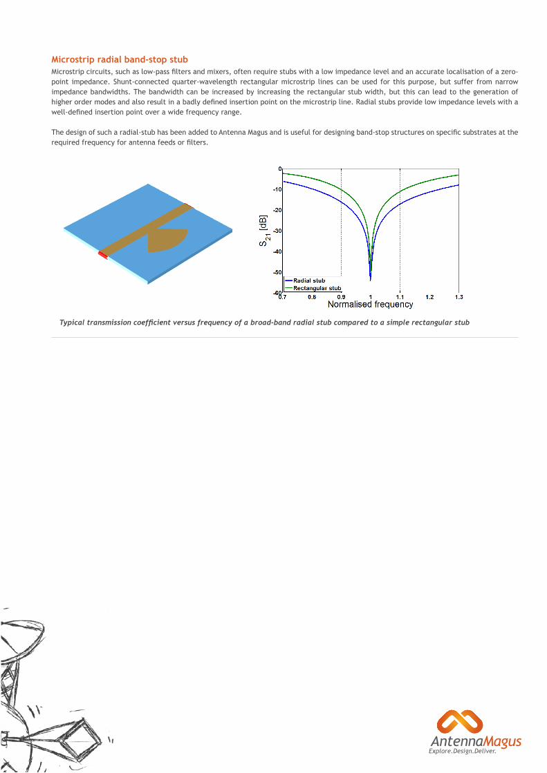
Microstrip circuits, such as low-pass filters and mixers, often require stubs with a low impedance level and an accurate localisation of a zero-point impedance. Shunt-connected quarter-wavelength rectangular microstrip lines can be used for this purpose, but suffer from narrow impedance bandwidths. The bandwidth can be increased by increasing the rectangular stub width, but this can lead to the generation of higher order modes and also result in a badly defined insertion point on the microstrip line. Radial stubs provide low impedance levels with a well-defined insertion point over a wide frequency range.
The design of such a radial-stub has been added to Antenna Magus and is useful for designing band-stop structures on specific substrates at the required frequency for antenna feeds or filters.
Microstrip radial band-stop stub
Typical transmission coefficient versus frequency of a broad-band radial stub compared to a simple rectangular stub