TT21/TT22 Mode S Transponder Installation Manual AQ TT21TT22... · TT21/TT22 Transponder...
69
TT21/TT22 Mode S Transponder Installation Manual 00560-00-AQ 22 September 2017 Trig Avionics Limited Heriot Watt Research Park Riccarton, Edinburgh EH14 4AP Scotland, UK Copyright Trig Avionics Limited, 2013
Transcript of TT21/TT22 Mode S Transponder Installation Manual AQ TT21TT22... · TT21/TT22 Transponder...

TT21/TT22 Mode S Transponder Installation Manual
00560-00-AQ 22 September 2017
Trig Avionics Limited Heriot Watt Research Park Riccarton, Edinburgh EH14 4AP Scotland, UK
Copyright Trig Avionics Limited, 2013

This page intentionally left blank

TT21/TT22 Transponder Installation Manual 22 September 2017 00560-00 Issue AQ
______________________
Trig Avionics Limited i
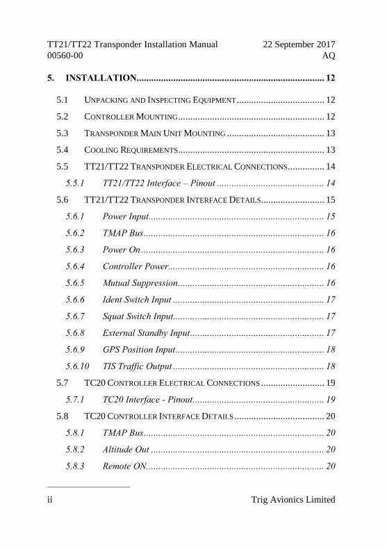
CONTENTS
1. PREFACE .......................................................................................... 1
1.1 PURPOSE....................................................................................... 1
1.2 SCOPE .......................................................................................... 1
1.3 CHANGES FROM PREVIOUS ISSUE ................................................... 1
1.4 DOCUMENT CROSS-REFERENCES ................................................... 1
2. INTRODUCTION ............................................................................. 2
2.1 TT21/TT22 DESCRIPTION ............................................................. 2
2.2 INTERFACES .................................................................................. 2
2.2.1 TT21/TT22 Transponder Unit ............................................... 2
2.2.2 TC20 Controller Unit ........................................................... 3
3. TECHNICAL SPECIFICATIONS.................................................... 5
3.1 TT21 TRANSPONDER UNIT (00675-00-01) ..................................... 5
3.2 TT22 TRANSPONDER UNIT (00745-00-01) ..................................... 6
3.3 TC20 CONTROL UNIT (00649-00) ................................................. 7
3.4 INSTALLATION APPROVAL ............................................................. 8
4. UNIT AND ACCESSORIES SUPPLIED .......................................... 9
4.1 TT21 MODE S TRANSPONDER ITEMS ............................................. 9
4.2 TT22 MODE S TRANSPONDER ITEMS ............................................. 9
4.3 TC20 CONTROLLER ITEMS ............................................................ 9
4.4 INSTALLATION KIT........................................................................ 9
4.5 REQUIRED ITEMS ........................................................................ 10
TT21/TT22 Transponder Installation Manual 22 September 2017 00560-00 AQ
______________________
ii Trig Avionics Limited
5. INSTALLATION............................................................................. 12
5.1 UNPACKING AND INSPECTING EQUIPMENT .................................... 12
5.2 CONTROLLER MOUNTING ............................................................ 12
5.3 TRANSPONDER MAIN UNIT MOUNTING ........................................ 13
5.4 COOLING REQUIREMENTS ............................................................ 13
5.5 TT21/TT22 TRANSPONDER ELECTRICAL CONNECTIONS ............... 14
5.5.1 TT21/TT22 Interface – Pinout ............................................ 14
5.6 TT21/TT22 TRANSPONDER INTERFACE DETAILS .......................... 15
5.6.1 Power Input ........................................................................ 15
5.6.2 TMAP Bus .......................................................................... 16
5.6.3 Power On ........................................................................... 16
5.6.4 Controller Power................................................................ 16
5.6.5 Mutual Suppression ............................................................ 16
5.6.6 Ident Switch Input .............................................................. 17
5.6.7 Squat Switch Input.............................................................. 17
5.6.8 External Standby Input ....................................................... 17
5.6.9 GPS Position Input ............................................................. 18
5.6.10 TIS Traffic Output .............................................................. 18
5.7 TC20 CONTROLLER ELECTRICAL CONNECTIONS .......................... 19
5.7.1 TC20 Interface - Pinout ...................................................... 19
5.8 TC20 CONTROLLER INTERFACE DETAILS ..................................... 20
5.8.1 TMAP Bus .......................................................................... 20
5.8.2 Altitude Out ....................................................................... 20
5.8.3 Remote ON ......................................................................... 20

TT21/TT22 Transponder Installation Manual 22 September 2017 00560-00 Issue AQ
______________________
Trig Avionics Limited iii
5.8.4 Power ................................................................................. 20
5.9 D CONNECTOR CRIMP TERMINALS ............................................... 20
5.10 WIRING CONSIDERATIONS ........................................................... 21
5.11 ANTENNA INSTALLATION ............................................................ 23
5.11.1 Antenna Ground Plane ....................................................... 23
5.11.2 Antenna Cable ................................................................... 24
5.11.3 TNC Connector .................................................................. 26
5.12 STATIC PRESSURE CONNECTION .................................................. 27
6. INSTALLATION SETUP AND TEST ........................................... 29
6.1 CONFIGURATION ITEMS ............................................................... 29
6.1.1 VFR Flight ID .................................................................... 29
6.1.2 Aircraft Address Programming ........................................... 30
6.1.3 VFR Squawk Code .............................................................. 30
6.1.4 Airspeed Category.............................................................. 30
6.1.5 Aircraft Category ............................................................... 31
6.1.6 Squat Switch Source ........................................................... 31
6.1.7 TIS Output.......................................................................... 31
6.1.8 GPS Input .......................................................................... 31
6.1.9 GPS/TIS Line Speed ........................................................... 32
6.1.10 GPS Certification Level ..................................................... 32
6.1.11 GPS NAC velocity .............................................................. 32
6.1.12 Aircraft Length and Width .................................................. 33
6.1.13 GPS Antenna Offset............................................................ 33
6.1.14 1090 MHz Receiver Installed ............................................. 33

TT21/TT22 Transponder Installation Manual 22 September 2017 00560-00 AQ
______________________
iv Trig Avionics Limited
6.1.15 UAT Receiver Installed ...................................................... 34
6.2 TEST AND CALIBRATION ITEMS .................................................... 34
6.2.1 Voltage Check .................................................................... 34
6.2.2 Altitude Encoder Calibration ............................................. 34
7. POST INSTALLATION CHECKS................................................. 38
8. NORMAL OPERATION ................................................................ 39
8.1 OVERVIEW .................................................................................. 39
8.2 DISPLAY ..................................................................................... 39
8.3 MODE SELECTOR KNOB .............................................................. 40
8.4 PUSH BUTTONS ........................................................................... 40
8.5 CODE SELECTOR KNOB ............................................................... 41
8.6 ALTITUDE ENCODER WARM UP ................................................... 41
8.7 GENERAL LOW TEMPERATURE OPERATION .................................. 41
8.8 ADS-B MONITOR ....................................................................... 42
8.9 DISPLAY BRIGHTNESS CONTROL .................................................. 42
8.10 WARNING MESSAGES .................................................................. 42
8.11 FAULT ANNUNCIATION................................................................ 42
9. CONTINUED AIRWORTHINESS................................................. 44
10. LIMITED WARRANTY ............................................................. 45
11. ENVIRONMENTAL QUALIFICATION FORMS .................... 46
12. ADS-B COMPLIANCE ............................................................... 52
12.1 ADS-B PARAMETERS SUPPORTED ................................................ 52

TT21/TT22 Transponder Installation Manual 22 September 2017 00560-00 Issue AQ
______________________
Trig Avionics Limited v
12.2 FAA 91.227 COMPLIANCE........................................................... 53
12.3 CS-ACNS COMPLIANCE ............................................................. 54
12.4 TSO C199 TABS COMPLIANCE ................................................... 55
12.5 AUTOMATIC AIR/GROUND DETERMINATION ................................ 55
12.6 ADS-B SUPPORT ........................................................................ 55
13. INSTALLATION DRAWINGS .................................................. 56
13.1 MOUNTING TRAY FIXING AND OVERALL DIMENSIONS .................... 56
13.2 FRONT PANEL CONTROLLER DIMENSIONS .................................... 57
13.3 FRONT PANEL CUT-OUT OPTIONS ................................................ 58
14. BASIC INTERCONNECT DIAGRAM ...................................... 60

TT21/TT22 Transponder Installation Manual 22 September 2017 00560-00 AQ
______________________
vi Trig Avionics Limited
This page intentionally left blank
TT21/TT22 Transponder Installation Manual 22 September 2017 00560-00 Issue AQ
______________________
Trig Avionics Limited 1
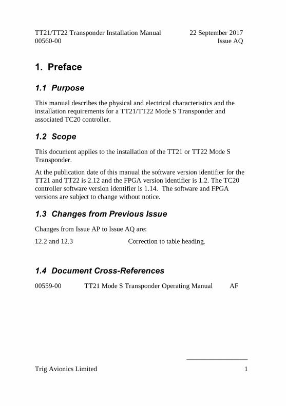
1. Preface
1.1 Purpose
This manual describes the physical and electrical characteristics and the installation requirements for a TT21/TT22 Mode S Transponder and associated TC20 controller.
1.2 Scope
This document applies to the installation of the TT21 or TT22 Mode S Transponder.
At the publication date of this manual the software version identifier for the TT21 and TT22 is 2.12 and the FPGA version identifier is 1.2. The TC20 controller software version identifier is 1.14. The software and FPGA versions are subject to change without notice.
1.3 Changes from Previous Issue
Changes from Issue AP to Issue AQ are:
12.2 and 12.3 Correction to table heading.
1.4 Document Cross-References
00559-00 TT21 Mode S Transponder Operating Manual AF

TT21/TT22 Transponder Installation Manual 22 September 2017 00560-00 AQ
______________________
2 Trig Avionics Limited
2. Introduction
2.1 TT21/TT22 Description
The TT21/TT22 Mode S transponder system is an ED-73C compliant Mode S level 2els datalink transponder, with support for ADS-B extended squitter, elementary surveillance and SI codes, which also meets the relevant environmental requirements of ED-14F. The TT21 has a nominal power output of 125 Watts, and meets the power output requirements for Class 2. The TT22 has a nominal power output of 250 watts, and meets the power output requirements for Class 1. The ADS-B function meets DO-260B class B0 for the TT21 and class B1S for the TT22. The TT21/TT22 is certified to ETSO 2C112b and ETSO C166a, and to FAA TSO C112c and C166b.
The TT21/TT22 transponder is controlled using a separate front panel controller, called the TC20. This allows the transponder to be mounted separately from the instrument panel, and reduces the amount of panel space taken by the transponder. The TC20 includes an altitude encoder. The TC20 is certified to ETSO 2C112b and ETSO C88a, and to FAA TSO C112c and TSO C88b.
The TT21/TT22 transponder runs from either 14 volt nominal or 28 volt nominal DC power supply with no configuration changes required.
The TT21/TT22 transponder responds to both legacy Mode A/C interrogations and to Mode S interrogations from both ground radar and airborne collision avoidance systems. In all cases, the interrogations are received by the transponder on 1030MHz, and replies are transmitted on 1090MHz.
2.2 Interfaces
2.2.1 TT21/TT22 Transponder Unit
The main transponder unit has a single TNC antenna connection and a single

TT21/TT22 Transponder Installation Manual 22 September 2017 00560-00 Issue AQ
______________________
Trig Avionics Limited 3
25 way D-type connector. The 25 way D-type interface provides the following services:
Power Input The TT21/TT22 operates on 11 to 33 Volts DC.
Front Panel Datalink
A two wire data link is used to connect the TT21/TT22 and the controller.
Front Panel Power The controller is powered from the transponder.
Remote On/Off The on-off switching is on the controller, and switches this input.
Ident input External IDENT switch input.
Standby input External standby input for dual transponder installations.
“On ground” input Allows automatic flight/ground mode switching for aircraft with a squat switch.
Suppression bus I/O ARINC compatible suppression bus signal used in aircraft with other pulse equipment, such as DME. This pin is both an input to and output from the transponder.
GPS Input Connection to a GPS supplying position input for ADS-B position reporting.
TIS Output Connection to a traffic display.
2.2.2 TC20 Controller Unit
The TC20 controller has a single 9 way D-type connector. It provides the following services:
Power Input The controller receives power from the transponder.
Front Panel Datalink A two wire data link is used to connect the TT21/TT22 and the controller.
Remote On/Off The on-off switching is on the controller, and controls this output.
Altitude Output An additional serial output on the TC20 provides

TT21/TT22 Transponder Installation Manual 22 September 2017 00560-00 AQ
______________________
4 Trig Avionics Limited
pressure altitude information that can be used for baro-aiding by certain GPS receivers.
TT21/TT22 Transponder Installation Manual 22 September 2017 00560-00 Issue AQ
______________________
Trig Avionics Limited 5
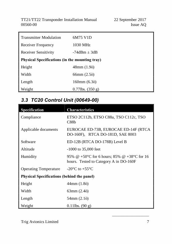
3. Technical Specifications
3.1 TT21 Transponder Unit (00675-00-01)
Specification Characteristics
Compliance ETSO 2C112b Class 2 Level 2els, ETSO C166a Class B0, TSO C112c Class 2 Level 2els, TSO C166b Class B0
FCC Identification VZI00675
Applicable documents EUROCAE ED-73C, EUROCAE ED-14F (RTCA DO-160F), RTCA DO-181D, RTCA DO-260B
Software ED-12B (RTCA DO-178B) Level B
Hardware DO-254 Level C
Power Requirements 11 – 33 Volts DC. Typical 5 Watts @ 14Volts.
Altitude 35,000 feet
Humidity 95% @ +50°C for 6 hours; 85% @ +38°C for 16 hours.
Tested to Category A in DO-160F
Operating Temperature -20°C to +70°C
Transmitter Frequency 1090MHz ± 1MHz
Transmitter Power 125 Watts nominal; 71 Watts minimum at antenna after allowing for 0.5dB connector losses and 1.5dB cable losses.
Transmitter Modulation 6M75 V1D
Receiver Frequency 1030 MHz
TT21/TT22 Transponder Installation Manual 22 September 2017 00560-00 AQ
______________________
6 Trig Avionics Limited
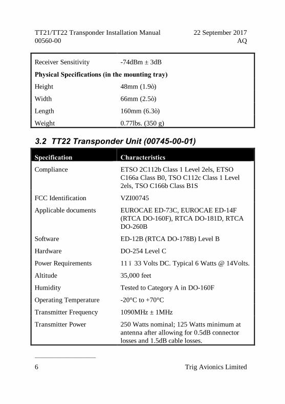
Receiver Sensitivity -74dBm ± 3dB
Physical Specifications (in the mounting tray)
Height 48mm (1.9”)
Width 66mm (2.5”)
Length 160mm (6.3”)
Weight 0.77lbs. (350 g)
3.2 TT22 Transponder Unit (00745-00-01)
Specification Characteristics
Compliance ETSO 2C112b Class 1 Level 2els, ETSO C166a Class B0, TSO C112c Class 1 Level 2els, TSO C166b Class B1S
FCC Identification VZI00745
Applicable documents EUROCAE ED-73C, EUROCAE ED-14F (RTCA DO-160F), RTCA DO-181D, RTCA DO-260B
Software ED-12B (RTCA DO-178B) Level B
Hardware DO-254 Level C
Power Requirements 11 – 33 Volts DC. Typical 6 Watts @ 14Volts.
Altitude 35,000 feet
Humidity Tested to Category A in DO-160F
Operating Temperature -20°C to +70°C
Transmitter Frequency 1090MHz ± 1MHz
Transmitter Power 250 Watts nominal; 125 Watts minimum at antenna after allowing for 0.5dB connector losses and 1.5dB cable losses.
TT21/TT22 Transponder Installation Manual 22 September 2017 00560-00 Issue AQ
______________________
Trig Avionics Limited 7
Transmitter Modulation 6M75 V1D
Receiver Frequency 1030 MHz
Receiver Sensitivity -74dBm ± 3dB
Physical Specifications (in the mounting tray)
Height 48mm (1.9”)
Width 66mm (2.5”)
Length 160mm (6.3”)
Weight 0.77lbs. (350 g)
3.3 TC20 Control Unit (00649-00)
Specification Characteristics
Compliance ETSO 2C112b, ETSO C88a, TSO C112c, TSO C88b
Applicable documents EUROCAE ED-73B, EUROCAE ED-14F (RTCA DO-160F), RTCA DO-181D, SAE 8003
Software ED-12B (RTCA DO-178B) Level B
Altitude -1000 to 35,000 feet
Humidity 95% @ +50°C for 6 hours; 85% @ +38°C for 16 hours. Tested to Category A in DO-160F
Operating Temperature -20°C to +55°C
Physical Specifications (behind the panel)
Height 44mm (1.8”)
Width 63mm (2.4”)
Length 54mm (2.1”)
Weight 0.11lbs. (90 g)

TT21/TT22 Transponder Installation Manual 22 September 2017 00560-00 AQ
______________________
8 Trig Avionics Limited
3.4 Installation Approval
The conditions and tests required for the TSO approval of the TT21/TT22 Mode S Transponder are minimum performance standards. It is the responsibility of those desiring to install this transponder on or within a specific type or class of aircraft to determine that the aircraft operating conditions are within the TSO standards. The transponder may be installed only if further evaluation by the user/installer documents an acceptable installation that is approved by the appropriate airworthiness authority.
TT21/TT22 Transponder Installation Manual 22 September 2017 00560-00 Issue AQ
______________________
Trig Avionics Limited 9
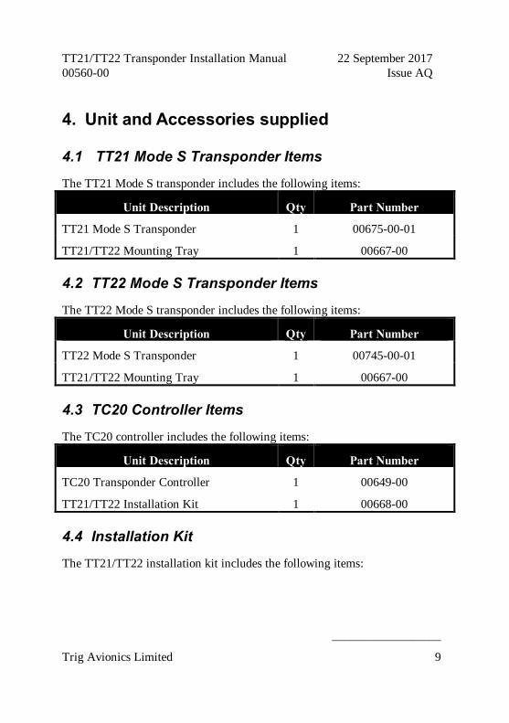
4. Unit and Accessories supplied
4.1 TT21 Mode S Transponder Items
The TT21 Mode S transponder includes the following items:
Unit Description Qty Part Number
TT21 Mode S Transponder 1 00675-00-01
TT21/TT22 Mounting Tray 1 00667-00
4.2 TT22 Mode S Transponder Items
The TT22 Mode S transponder includes the following items:
Unit Description Qty Part Number
TT22 Mode S Transponder 1 00745-00-01
TT21/TT22 Mounting Tray 1 00667-00
4.3 TC20 Controller Items
The TC20 controller includes the following items:
Unit Description Qty Part Number
TC20 Transponder Controller 1 00649-00
TT21/TT22 Installation Kit 1 00668-00
4.4 Installation Kit
The TT21/TT22 installation kit includes the following items:

TT21/TT22 Transponder Installation Manual 22 September 2017 00560-00 AQ
______________________
10 Trig Avionics Limited
Unit Description Qty Part Number
TT21/TT22 Transponder Installation Manual
1 00560-00
TT21/TT22 Pilots Operating Manual 1 00559-00
Mounting adapter (circular hole adapter) 2 00678-00
Connector Co-axial TNC 1 00723-00
Headshell, 9 Way 1 00725-00
Headshell, 25 way 1 00726-00
9 way D-type contact housing (female) 1 00727-00
25 way D-type contact housing (male) 1 00728-00
Crimp Terminal, Male, 22-24 AWG 20 00729-00
Crimp Terminal, Female, 22-24 AWG 9 00730-00
Static tubing, EPDM 5mm ID 1 00731-00
Hose T piece 1 00732-00
Hose Adapter 2 00733-00
Hose clip, small 6 00734-00
Hose clip, large 2 00735-00
Long mounting screws, 4-40 thread 4 00736-00
Short mounting screws, 4-40 thread 4 00737-00
4.5 Required Items
Additional items you will require, but which are not in the TT21/TT22 package, include:
• Antenna and fixing hardware. The TT21/TT22 is compatible with any transponder antenna approved to ETSO C74 or 2C112 or

TT21/TT22 Transponder Installation Manual 22 September 2017 00560-00 Issue AQ
______________________
Trig Avionics Limited 11
equivalent.
• Cables. You need to supply and fabricate all required cables. Guidance on cable types is given in section 5 below.
• Fixings. To secure the transponder tray to the airframe you will need at least 3 flat head screws and three self-locking nuts. If the aircraft does not have existing mounting provisions you may need to fabricate additional brackets to support the transponder tray.
To support the optional ADS-B features a GPS receiver with an appropriate serial output is required. To support the optional TIS features a display with an appropriate serial input is required.
TT21/TT22 Transponder Installation Manual 22 September 2017 00560-00 AQ
______________________
12 Trig Avionics Limited
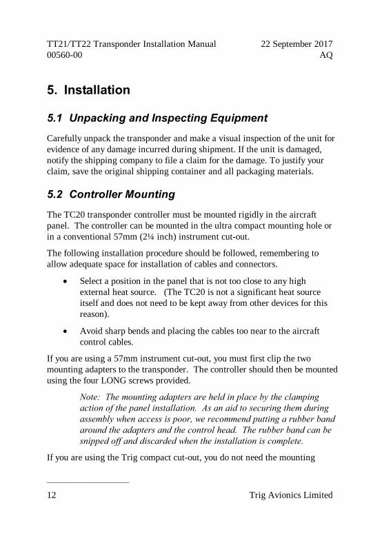
5. Installation
5.1 Unpacking and Inspecting Equipment
Carefully unpack the transponder and make a visual inspection of the unit for evidence of any damage incurred during shipment. If the unit is damaged, notify the shipping company to file a claim for the damage. To justify your claim, save the original shipping container and all packaging materials.
5.2 Controller Mounting
The TC20 transponder controller must be mounted rigidly in the aircraft panel. The controller can be mounted in the ultra compact mounting hole or in a conventional 57mm (2¼ inch) instrument cut-out.
The following installation procedure should be followed, remembering to allow adequate space for installation of cables and connectors.
• Select a position in the panel that is not too close to any high external heat source. (The TC20 is not a significant heat source itself and does not need to be kept away from other devices for this reason).
• Avoid sharp bends and placing the cables too near to the aircraft control cables.
If you are using a 57mm instrument cut-out, you must first clip the two mounting adapters to the transponder. The controller should then be mounted using the four LONG screws provided.
Note: The mounting adapters are held in place by the clamping action of the panel installation. As an aid to securing them during assembly when access is poor, we recommend putting a rubber band around the adapters and the control head. The rubber band can be snipped off and discarded when the installation is complete.
If you are using the Trig compact cut-out, you do not need the mounting

TT21/TT22 Transponder Installation Manual 22 September 2017 00560-00 Issue AQ
______________________
Trig Avionics Limited 13
adapters. The controller should be mounted using the four SHORT screws provided. The screws supplied are appropriate for panel thicknesses from 3 mm to 5 mm. If a thinner panel is used, you may need to exchange the screws for shorter versions since they can bottom out in the mounting holes.
If alternate screws are required, please note that the mounting thread in each case is 4-40.
5.3 Transponder Main Unit Mounting
The TT21/TT22 Mode S transponder is designed to be mounted in any convenient location in the cockpit, the cabin, or an avionics bay.
The following installation procedure should be followed, remembering to allow adequate space for installation of cables and connectors.
• Select a position in the aircraft that is not too close to any high external heat source. (The TT21/TT22 is not a significant heat source itself and does not need to be kept away from other devices for this reason).
• Avoid sharp bends and placing the cables too near to the aircraft control cables.
• Secure the mounting tray (p/n 00667-00) to the aircraft via the three (3) mounting holes in the tray. The tray should be mounted to a flat surface - it is important that the tray is supported at the dimples as well as the three mounting points.
• Put the TT21/TT22 transponder into the secured mounting tray by hooking the connector end under the lip on the tray.
• Lock the TT21/TT22 transponder into the mounting tray by clipping the retaining wire over the lugs on the opposite end.
5.4 Cooling Requirements
The TT21/TT22 Mode S transponder meets all applicable ETSO requirements without forced air-cooling.
TT21/TT22 Transponder Installation Manual 22 September 2017 00560-00 AQ
______________________
14 Trig Avionics Limited
Attention should however be given to the incorporation of cooling provisions to limit the maximum operating temperature if the TT21/TT22 is installed in close proximity to other avionics. The reliability of equipment operating in close proximity in an avionics bay can be degraded if adequate cooling is not provided.
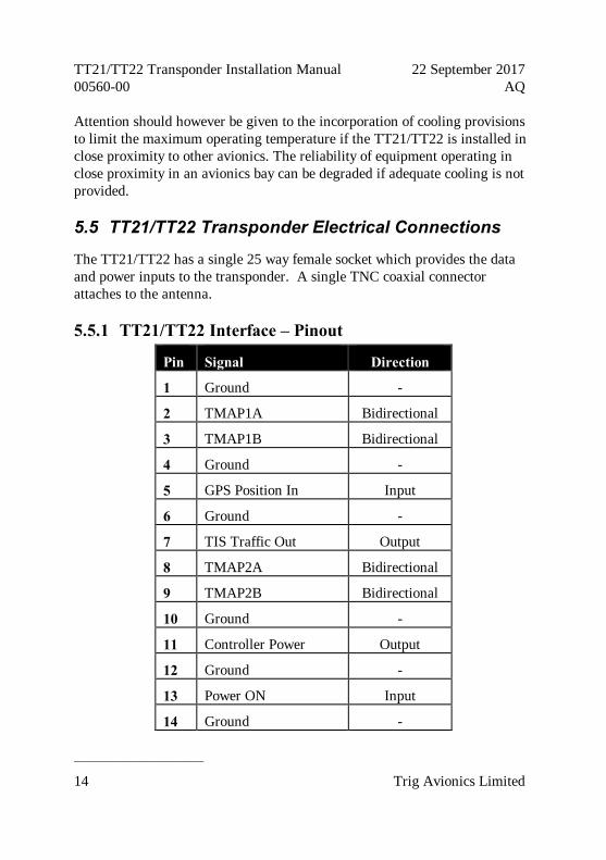
5.5 TT21/TT22 Transponder Electrical Connections
The TT21/TT22 has a single 25 way female socket which provides the data and power inputs to the transponder. A single TNC coaxial connector attaches to the antenna.
5.5.1 TT21/TT22 Interface – Pinout
Pin Signal Direction
1 Ground -
2 TMAP1A Bidirectional
3 TMAP1B Bidirectional
4 Ground -
5 GPS Position In Input
6 Ground -
7 TIS Traffic Out Output
8 TMAP2A Bidirectional
9 TMAP2B Bidirectional
10 Ground -
11 Controller Power Output
12 Ground -
13 Power ON Input
14 Ground -

TT21/TT22 Transponder Installation Manual 22 September 2017 00560-00 Issue AQ
______________________
Trig Avionics Limited 15
15 11-33V DC Input
16 Reserved -
17 External Standby In Input
18 Mutual Suppression Bidirectional
19 Squat Switch In Input
20 Ident Switch In Input
21 Reserved -
22 Reserved -
23 Reserved -
24 Reserved -
25 Reserved -
The following diagram shows the connector orientation as viewed from the wiring side.
5.6 TT21/TT22 Transponder Interface Details
5.6.1 Power Input
The power supply can be 11-33 Volts DC; no voltage adjustment is required. Use a 3 Amp circuit breaker for power supply protection to the TT21/TT22.
It is always good practice to use more than one ground wire in an installation. This is particularly important when the transponder is mounted on a non-conducting surface, such as a composite structure. With only one wire there

TT21/TT22 Transponder Installation Manual 22 September 2017 00560-00 AQ
______________________
16 Trig Avionics Limited
could be only a single grounding path for the transponder, controller and antenna.
Note: The transponder power input is not protected against reversed power connections. Reversing the power and ground inputs to the transponder will destroy it. Check wiring before applying power.
5.6.2 TMAP Bus
TMAP is a Trig proprietary bus based on RS485 signalling. It provides a bi-directional interface between the transponder and the control head. Each TMAP interface comprises a balanced pair of signals, called A and B, both of which must be connected for communication to work.
There are two sets of TMAP pins on the TT21/TT22, TMAP1 A and B, and TMAP2 A and B. This is to support future installation wiring options. The two sets are identical, and either pair (TMAP1 or TMAP2) may be used to connect to the control head.
5.6.3 Power On
The TT21/TT22 power supply can be directly controlled by this discrete input. The input is active low, so that the TT21/TT22 will power up whenever the input is held low. This signal is intended to connect to the TC20 Remote ON output.
5.6.4 Controller Power
The TC20 controller does not connect to aircraft power – it receives power from the TT21/TT22 using this output. The TT21/TT22 provides 6.5 Volts to the TC20. This output includes short circuit protection, and no fuse is required between the TT21/TT22 and the TC20.
5.6.5 Mutual Suppression
Mutual suppression allows two or more transmitters on adjacent frequencies to inhibit the other transmitters when one is active to limit the interference

TT21/TT22 Transponder Installation Manual 22 September 2017 00560-00 Issue AQ
______________________
Trig Avionics Limited 17
effects. It is commonly used between transponders and DME systems, and between transponders and collision avoidance systems.
The Suppress I/O on pin 18 is an ARINC compatible suppression bus interface, which acts as both an input and an output. The TT21/TT22 will assert this signal when it is transmitting, and can be suppressed by other equipment that asserts the signal. The TT21/TT22 will drive approximately 24 Volts on the output (independently of supply voltage), and will treat the input as active whenever the bus has greater than 10 Volts.
5.6.6 Ident Switch Input
The Ident switch input allows the IDENT function to be selected using a remote switch. The input is active low, and will be asserted when the voltage to ground is pulled below approximately 4 Volts.
5.6.7 Squat Switch Input
The Squat switch input allows the transponder to automatically switch between Airborne and Ground modes, and affects both the Mode S reply behaviour and the ADS-B reporting behaviour. The input will be asserted when the voltage to ground is pulled below approximately 4 Volts. The logical sense of the input can be programmed to be either active low or active high.
On an aircraft with no appropriate squat switch circuit this input should be left unconnected, and the transponder programmed to ignore the input.
Note: On an aircraft without a squat switch, but configured for ADS-B Out, the transponder can use the GPS data to determine the Airborne/Ground mode automatically.
5.6.8 External Standby Input
This input, when held low, places the transponder in Standby mode. It should be used to switch between transponders in an installation with two transponders. The input is active low, and will be asserted when the voltage

TT21/TT22 Transponder Installation Manual 22 September 2017 00560-00 AQ
______________________
18 Trig Avionics Limited
to ground is pulled below approximately 4 Volts.
5.6.9 GPS Position Input
The GPS position input is required to support ADS-B functionality. The GPS position input is an RS232 input to the transponder. The ADS-B features are optional – no GPS is required for normal Mode S Elementary Surveillance.
The TT21/TT22 GPS input can recognise the following protocols:
• Industry standard “Aviation” protocol
• NMEA 0183 protocol ($GPRMC sentence is required)
• Freeflight and Accord NexNav GPS proprietary protocols
• Garmin ADS-B protocol, including ADS-B plus
• Trig ADS-B protocol
• C199 TABS compliant GPS using NMEA protocol
• Trig TN72 GPS protocol
The interface speed can be selected between 4800, 9600, 19200 and 38400 bps.
Some of the protocols listed above may not contain all the required data for a compliant ADS-B message, depending on the intended airspace regulations. For further information refer to Section 12 (ADS-B Compliance) of this manual.
5.6.10 TIS Traffic Output
The TIS traffic is an RS232 output and supports the display of uplinked Traffic Information Service messages. The TT21/TT22 TIS output can drive the Trig proprietary traffic protocol, and can also support the format used by certain Garmin handheld displays, including the 495, 496, 695 and 696.
Note: TIS is a Mode S uplink service that is provided by some US approach radars. TIS coverage is limited to the coverage areas of

TT21/TT22 Transponder Installation Manual 22 September 2017 00560-00 Issue AQ
______________________
Trig Avionics Limited 19
those radars. There is no TIS provision outside the USA.
5.7 TC20 Controller Electrical Connections
The TC20 controller has a single 9 way D type male connector to link to the transponder, and optionally to connect to a GPS for baro-aiding.
5.7.1 TC20 Interface - Pinout
Pin Signal Direction
1 Ground -
2 TMAPA Bidirectional
3 TMAPB Bidirectional
4 Altitude Out Output
5 Reserved Input
6 Ground -
7 Remote ON Output
8 Power Input
9 Ground -
The following diagram shows the connector orientation as viewed from the wiring side.
TT21/TT22 Transponder Installation Manual 22 September 2017 00560-00 AQ
______________________
20 Trig Avionics Limited
5.8 TC20 Controller Interface Details
5.8.1 TMAP Bus
TMAP is a Trig proprietary bus based on RS485 signalling. It provides a bi-directional interface between the transponder and the control head. Each TMAP interface comprises a balanced pair of signals, called A and B, both of which must be connected for communication to work.
TMAP A and B lines on the controller should be connected to the corresponding A and B lines of either TMAP1 or TMAP2 on the TT21/TT22.
5.8.2 Altitude Out
The TC20 incorporates an altitude encoder. Certain GPS receivers can benefit from having altitude information supplied to them. The TC20 reports pressure altitude on this pin as an RS232 serial data format, at 9600 bps, using the format commonly called “Icarus” or “Garmin” format.
5.8.3 Remote ON
This output is connected directly to the Power/Mode switch on the TC20, and should be connected to the Power ON discrete input of the TT21/TT22.
5.8.4 Power
The TC20 uses 6.5 volts which is available from the TT21/TT22 transponder. This input should NOT be connected to aircraft power.
5.9 D Connector Crimp Terminals
The 25 way and 9 way connectors supplied with the TT21/TT22 installation kit are MIL standard versions of the popular sub miniature D type connector family, and use individual crimp terminals and a receptacle. The MIL specification for this family of connectors is MIL-C-24308. We supply crimp terminals because these are more reliable than soldered connections, and are
TT21/TT22 Transponder Installation Manual 22 September 2017 00560-00 Issue AQ
______________________
Trig Avionics Limited 21
easier to assemble in-situ in an aircraft, where soldering is impractical. They also allow individual wires to be removed and replaced in a receptacle without replacing the whole connector.
The pin contacts, used in the 25 way connector, conform to MIL part number M39029/64-369, and are suitable for wire gauges from 20 to 24 AWG.
The socket contacts, used in the 9 way connector, conform to MIL part number M39029/63-368, and are also suitable for wire gauges from 20 to 24 AWG.
These contacts are widely used in avionics installation, and there are many tools available on the market that will reliably crimp them to the wiring. Because the contacts are a MIL standard, there is also a MIL standard for the crimp tool, although other proprietary solutions are also available.
The MIL reference for the basic style of hand tool is M22520/2-01. This style of tool can crimp many different contact types, and relies on interchangeable "positioners" to hold the actual contact in use. The MIL reference for the positioner that you need for the crimps we supply is M22520/2-08.
Any tool that complies with these references can be used to crimp these contacts. One of the most popular vendors of these small hand tools is Daniels Manufacturing Corporation (see www.dmctools.com). Their AFM8 hand tool complies with M22520/2-01, and their K13-1 positioner is M22520/2-08 compliant, so the combination will crimp the supplied connectors.
Once crimped, the contacts should be slotted into the rear of the connector shell. Push the contact in until the retaining tab clicks into place. Tug gently to confirm the contact is locked in place.
5.10 Wiring Considerations
The connection from the TT21/TT22 transponder to the TC20 uses a minimum of six (6) signal lines; the TMAP pair, the Power and Ground pair, and the Remote On discrete line plus associated ground line. In a certified installation the normal wire choice would be Tefzel hook-up wire. Wire of 20 AWG is more than adequate for the task; in installations where weight is an

TT21/TT22 Transponder Installation Manual 22 September 2017 00560-00 AQ
______________________
22 Trig Avionics Limited
issue, wire of 22 or 24 AWG can also be used. Where lighter wires than 20 AWG are used the individual wires should be laced together for support.
The TT21/TT22/TC20 was tested and certified using unshielded, untwisted wiring, and that is sufficient for a certified installation. There may however be technical benefits of improved electromagnetic emissions and susceptibility to and from the transponder system if the two wires of the TMAP pair are lightly twisted together – one twist per 1 to 2 inches is appropriate. This may reduce interference and break-through on adjacent audio wiring if it is not possible to route them separately. For tidiness and consistency the other pairs in the bundle can also be twisted, but there will be no particular difference in behaviour.
The distance between the TT21/TT22 transponder and the TC20 controller is limited by the impedance of the wire between them. The TC20 is powered from the TT21/TT22, not from aircraft power, and therefore the acceptable voltage drop in the power line is what limits the distance. The TC20 needs an impedance of less than 0.5 ohm in the power line for satisfactory operation. The following table gives guidelines for typical aircraft hook-up wire. Note that different brands may vary – check your supplier for details.
Gauge Ohm/km Length for 0.5 Ohm
20 AWG 35 14.2 m
22 AWG 64 7.8 m
24 AWG 99 5.0 m
An alternative to a harness built from individual wires, particularly for a long cable run, is to use a multi-core cable. Aviation grade cable with 6 or more cores is often more expensive than the individual wires, and therefore is not generally a good choice for a certified aircraft. For aircraft where those considerations do not apply however, an attractive alternative solution may be to use 3 pair or 4 pair data cable.
Whilst appropriate cables may exist, please note that not all data cable is suitable for this application. Cables with solid cores should not be used, and cables should be selected based on the wear characteristics of their insulation
TT21/TT22 Transponder Installation Manual 22 September 2017 00560-00 Issue AQ
______________________
Trig Avionics Limited 23
material, including temperature rating, resistance to solvents and oils, and flammability. Most inexpensive commercial data cables have poor flammability properties.
5.11 Antenna Installation
The antenna should be installed according to the manufacturer’s instructions.
The following considerations should be taken into account when siting the Antenna.
• The antenna should be well removed from any projections, the engine(s) and propeller(s). It should also be well removed from landing gear doors, access doors or others openings which will break the ground plane for the antenna.
• The antenna should be mounted on the bottom surface of the aircraft and in a vertical position when the aircraft is in level flight.
• Avoid mounting the antenna within 3 feet of the ADF sense antenna or any COMM antenna and 6 feet from the transponder to the DME antenna.
• Where practical, plan the antenna location to keep the cable lengths as short as possible and avoid sharp bends in the cable to minimise the VSWR.
Electrical connection to the antenna should be protected to avoid loss of efficiency as a result of the presence of liquids or moisture. All antenna feeders shall be installed in such a way that a minimum of RF energy is radiated inside the aircraft.
5.11.1 Antenna Ground Plane
When a conventional aircraft monopole antenna is used it relies on a ground plane for correct behaviour. For ideal performance the ground plane should be large compared to the wavelength of the transmission, which is 275mm. In a metal skinned aircraft this is usually easy to accomplish, but is more difficult in a composite or fabric skinned aircraft. In these cases a metallic

TT21/TT22 Transponder Installation Manual 22 September 2017 00560-00 AQ
______________________
24 Trig Avionics Limited
ground plane should be fabricated and fitted under the antenna.
The ground plane should be as large as you can sensibly make it. Because it is a function of the wavelength of the transmission, the smallest practical ground plane for a transponder is a square around 120mm per side; as the size increases the performance improves until the ground plane is around 700mm on each side. Anything much larger than that size is unlikely to show significant further improvement.
The thickness of the material used to construct the ground plane is not critical, providing it is sufficiently conductive. A variety of proprietary mesh and grid solutions are available. Heavyweight cooking foil meets the technical requirements, but obviously needs to be properly supported.
5.11.2 Antenna Cable
The TT21 is designed to meet Class 2 requirements with an allowance of 2 dB for loss in the connectors and cable used to connect it to the antenna. The TT22 is designed to meet Class 1 requirements with the same 2 dB allowance. Excessive loss will degrade both transmitter output power and receiver sensitivity.
Allowing 0.25dB loss for the connector at each end of the antenna cable assembly leaves an allowance of 1.5dB maximum loss for the cable itself.
An acceptable cable:
• Has less than 1.5dB loss for the run length needed
• Has a characteristic impedance of 50 Ohms
• Has double braid screens or has a foil and braid screen
Once the cable run length is known, a cable type with low enough loss per metre that meets the above requirements can be chosen. Longer runs require lower loss cable. Consider moving the TT21/TT22 closer to the antenna to minimise the losses in the antenna cable – subject to the limits identified above, the TT21/TT22 can be at any distance from the control head without affecting performance in any way.

TT21/TT22 Transponder Installation Manual 22 September 2017 00560-00 Issue AQ
______________________
Trig Avionics Limited 25
Note: Low loss cable typically uses foamed or cellular dielectrics and foil screens. These make such cables especially prone to damage from too-tight bends or from momentary kinking during installation. Once kinked, these cables do not return to full performance when straightened.
The following table is a guide to the maximum usable lengths of some common cable types. Actual cable loss varies between manufacturers, there are many variants, and the table is therefore based on typical data. Use it as a guide only and refer to the manufacturer’s data sheet for your specific chosen cable for accurate values.
Max Length
in Metres
Max Length in Feet
Insertion Loss
dB/metre at 1090MHz
MIL-C-17 Cables
Electronic Cable
Specialists Type
SSB Electronic
2.54 8’ 4” 0.59 M17/128 (RG400)
3.16 10’ 4” 0.47 3C142B
3.81 12’ 6” 0.39 M17/112 (RG304)
4.50 14’ 9” 0.33 Aircell 5
5.25 17’ 3” 0.29 M17/127 (RG393)
311601
6.42 21’ 1” 0.23 311501
6.81 22’ 4” 0.22 Aircell 7
8.22 26’ 11” 0.18 311201
12.59 41’ 3” 0.12 310801
Contact Electronic Cable Specialists on +1 414 421 5300 or at www.ecsdirect.com for their data sheets. Contact SSB-Electronic GmbH on +49-2371-95900 or at www.ssb.de for their data sheets.

TT21/TT22 Transponder Installation Manual 22 September 2017 00560-00 AQ
______________________
26 Trig Avionics Limited
When routing the cable, ensure that you:
• Route the cable away from sources of heat.
• Route the cable away from potential interference sources such as ignition wiring, 400Hz generators, fluorescent lighting and electric motors.
• Allow a minimum separation of 300mm (12 inches) from an ADF antenna cable.
• Keep the cable run as short as possible.
• Avoid routing the cable round tight bends.
• Avoid kinking the cable even temporarily during installation.
• Secure the cable so that it cannot interfere with other systems.
5.11.3 TNC Connector
This section describes the technique for attaching the antenna cable to the supplied TNC connector.
If a low-loss cable is needed that has too large a dielectric diameter to fit the supplied connector, a short length (up to 150mm or 6 inches) of smaller cable may be used with suitable mating connectors to adapt to the transponder connector.
The supplied connector can be completed using a wide range of commercial crimp tools (for example the Tyco 5-1814800-3). The die apertures for the inner pin and the outer shield should be approximately 1.72 mm and 5.41 mm respectively.
• Strip back the coax cable to the dimensions in the table, as shown in the diagram below. Slide 25 mm (1 inch) of heat shrink tubing over the cable.
• Slide the outer crimp sleeve over the cable – it must go on before securing the centre contact.

TT21/TT22 Transponder Installation Manual 22 September 2017 00560-00 Issue AQ
______________________
Trig Avionics Limited 27
Dimension Cut size (mm)
Cut size (inches)
A 17.5 0.69
B 7.2 0.28
C 4.8 0.19
• Crimp the centre contact to the cable.
• Insert the cable into the connector – the centre contact should click into place in the body, the inner shield should be inside the body of the connector and the outer shield should be outside the body.
• Crimp the outer sleeve over the shield.
• Slide heat shrink tubing forward (flush to connector) and heat to shrink the tubing.
5.12 Static Pressure Connection
The TC20 controller includes an altitude encoder which must be connected to the same source of static pressure as the primary altimeter on the aircraft. The TC20 static pressure port provides a mounting spigot intended for nominal 5mm or 3/16 inch inside diameter tubing. A length of 5mm EPDM rubber tubing is included in the installation kit to facilitate connection to the aircraft static system.
Choose a point in the existing static pressure line that is as close as practical to the TC20. Cut the static pressure line, and use the supplied T fitting to

TT21/TT22 Transponder Installation Manual 22 September 2017 00560-00 AQ
______________________
28 Trig Avionics Limited
connect the altitude encoder. Take care not to contaminate the inside of the static line when cutting or inserting the connectors.
The following diagram shows the general arrangement, although other combinations may be used:
For aircraft with ¼ inch static lines, two adapters are provided which can convert from ¼ inch inside diameter hoses to the 5 mm hose in the install kit.
In all cases, the static line should include drainage provisions and should be routed in accordance with CS 23.1325 or other applicable airworthiness provisions for the aircraft.

TT21/TT22 Transponder Installation Manual 22 September 2017 00560-00 Issue AQ
______________________
Trig Avionics Limited 29
6. Installation Setup and Test The TT21/TT22 uses a simple setup system to program important system parameters, including the Mode S address. In the original factory configuration, the setup screen is the first thing that runs when you switch on the transponder. If the transponder has already been configured, and you want to access the setup screen again, hold down the FN button while switching on the transponder and the setup system will run.
The script will prompt for the following configuration items:
• VFR Flight ID (Registration)
• Mode S Address
• VFR Squawk Code
• Aircraft Maximum Airspeed
• Aircraft Category
• Squat switch source, if fitted
• TIS output format, if used
• GPS position source, if fitted, and ADS-B parameters
This setup mode also allows the recalibration of the altitude encoder.
All the programming is accomplished using the right hand rotary knob and the ENT and FN buttons. Make all input selections using the rotary knob. Pressing the ENT button accepts the current input and advances to the next input item. Pressing the FN button moves directly to the next screen.
6.1 Configuration Items
6.1.1 VFR Flight ID
The default Flight ID for an aircraft not on an IFR flight plan should be the

TT21/TT22 Transponder Installation Manual 22 September 2017 00560-00 AQ
______________________
30 Trig Avionics Limited
aircraft registration. Enter the aircraft registration using the rotary knob and the ENT button.
Note that the aircraft registration is loaded as letters and numbers only. There are no dashes or other punctuation marks, and no spaces can be inserted. When you enter a space it finishes the data entry and moves to the next item.
6.1.2 Aircraft Address Programming
The Mode S Address is a 24 bit number issued to the aircraft by the registration authority for the aircraft. These addresses are usually written as a 6 digit hexadecimal number, although you may also encounter one written as an 8 digit octal number. The TT21/TT22 only understands the hexadecimal format, so you must first convert an octal number to hexadecimal.
There is an Octal to Hexadecimal converter tool in the support section of the Trig Avionics web site.
The Mode S address will be automatically populated if a valid USA registration has been entered at the previous step.
If the Mode S address is not already populated, enter the 6 digit aircraft address using the rotary knob and the ENT button.
6.1.3 VFR Squawk Code
When the pilot presses the VFR button, a pre-programmed code will replace the current squawk code. The pre-programmed code is set up here; the choice of code will depend on the normal location of the aircraft. In the USA, the VFR squawk code is 1200. In most parts of Europe, the VFR squawk code should be set to 7000.
Enter the 4 digit squawk code using the rotary knob and the ENT button.
6.1.4 Airspeed Category
Mode S transponders can transmit their maximum airspeed characteristics to

TT21/TT22 Transponder Installation Manual 22 September 2017 00560-00 Issue AQ
______________________
Trig Avionics Limited 31
aircraft equipped with TCAS. This information is used to help identify threats and to plan avoiding action by the TCAS equipped aircraft. The airspeeds are grouped in ranges; using the rotary knob, select the range that corresponds to the aircraft.
6.1.5 Aircraft Category
To assist ATC tracking of aircraft, an aircraft category can be transmitted by Mode S transponders. Using the rotary knob, select the aircraft category that most closely matches the aircraft the transponder is installed in. If the transponder is fitted to a vehicle rather than an aircraft, select “Surface Vehicle”.
6.1.6 Squat Switch Source
The Squat switch input allows the transponder to automatically switch between Airborne and Ground modes, and to automatically start and stop the flight timer. The sense of the squat switch input can be selected using the rotary knob. If the squat switch input is not connected the “Not Connected” option must be selected.
6.1.7 TIS Output
If the aircraft has a Traffic Information Service (TIS) compatible display connected to the transponder, select the appropriate interface protocol using the rotary knob.
Note: TIS is a Mode S uplink service that is provided by some US approach radars. TIS coverage is limited to the coverage areas of those radars; there is no TIS provision outside the USA.
6.1.8 GPS Input
If a GPS is connected for ADS-B position reporting, select the appropriate interface protocol using the rotary knob.
TT21/TT22 Transponder Installation Manual 22 September 2017 00560-00 AQ
______________________
32 Trig Avionics Limited
6.1.9 GPS/TIS Line Speed
If a GPS input or TIS output has been configured, you should select the appropriate line speed using the rotary knob. Traffic displays using the Garmin protocol run at 9600 bps. Panel mount GPS units with Aviation format outputs generally also run at 9600 bps. NMEA GPS units generally run at 4800 bps. Trig TN70, Freeflight 1201 and NexNav 3101 GPS receivers run at 19200 bps. The Trig TN72 runs at 9600 bps.
Note: The TIS output and GPS input speeds are not separately controlled on the TT21/TT22. Not all combinations of GPS input and TIS output will be usable if the external devices operate on fixed bit rates and are different to each other.
6.1.10 GPS Certification Level
An important metric for ADS-B ground system behaviour is the SDA or System Design Assurance level. It is intended to reflect the probability that the GPS position source is providing erroneous information, and is based on the certification standard that was used by the GPS vendor. This will be indicated in the form of a letter code (A to D) on the data plate or installation documentation for the GPS in accordance with the standards DO-178B and DO-254, for example “DO-178B level C”. If both standards are reported but at different levels, use the lower standard (higher letter).
This configuration item is not required if the C199 TABS GPS source is selected.
6.1.11 GPS NAC velocity
Another metric that the ADS-B ground system uses to help it track the aircraft is NACv. NACv is the Navigational Accuracy Category for velocity, and is a design feature of the GPS receiver. It represents the error bound for velocity that the GPS may report in acceleration/deceleration or turning manoeuvres. You can find this information from your GPS installation manual.
TT21/TT22 Transponder Installation Manual 22 September 2017 00560-00 Issue AQ
______________________
Trig Avionics Limited 33
This configuration item is not required if the C199 TABS GPS source is selected.
6.1.12 Aircraft Length and Width
On the ground, ADS-B transmits encoded aircraft size information which is used by ATC to identify taxiing routes and potential conflicts. When configured for ADS-B, the TT21/TT22 will ask for the aircraft length and width (wingspan), in metres, and will calculate the appropriate size code for transmission.
6.1.13 GPS Antenna Offset
The GPS antenna offset is used together with the aircraft length and width to manage taxiway conflicts. A typical GPS installation does not report the geographic position of the centre of the aircraft, or even the tip of the nose of the aircraft; instead it usually reports the location of the actual GPS antenna (not the GPS receiver). In normal flight operations this distinction is of no practical importance at all, but if ADS-B is used to manage taxiway conflicts, a significant offset in antenna position could mean that the aircraft is not in the same place as the ADS-B reported position. Although primarily intended for position correction on large transport aircraft, General Aviation aircraft can also have a significant offset. For example, if the aircraft has a long tail boom and the GPS antenna is on the top of the tail, the GPS position could be 4 metres or more from the nose of the aircraft.
Enter the position of the GPs antenna relative to the nose of the aircraft. The position is stored and transmitted to the nearest 2 metres; great accuracy in measurement is not required.
6.1.14 1090 MHz Receiver Installed
The ADS-B transmissions include an indication to the ground stations of whether your aircraft includes a 1090 MHz ADS-B receiver. This can be used by the ground stations to manage the volume of traffic they must send. Set this to “Yes” if the aircraft has a 1090 MHz ADS-B receiver installed.

TT21/TT22 Transponder Installation Manual 22 September 2017 00560-00 AQ
______________________
34 Trig Avionics Limited
6.1.15 UAT Receiver Installed
The ADS-B transmissions include an indication to the ground stations of whether your aircraft includes a UAT ADS-B receiver. This can be used by the ground stations to manage the volume of traffic they must send. Set this to “Yes” if the aircraft has a UAT receiver installed.
6.2 Test and Calibration items
6.2.1 Voltage Check
The Voltage Check screen displays the current input voltage received by the control head from the TT21/TT22. Whilst displaying this screen theTC20 will exercise certain internal functions in the controller, including periodically turning on the heater circuit. The purpose of these exercises is to present a changing load on the power lines from the TT21/TT22. If you suspect a potential problem with the wiring to the controller, it is worth monitoring the displayed voltage for several seconds to find the worst-case reading.
The nominal voltage is 6.5 Volts. The displayed value may be lower due to cable impedance. If the voltage is below 6.0 Volts, then the interface cable has too much impedance, and you should review the choice of cable.
6.2.2 Altitude Encoder Calibration
The Altitude Encoder Calibration allows you to adjust the built-in altitude encoder to ensure that the altitude transmitted by the transponder corresponds to the altitude seen by the pilot on the primary altimeter. This process is normally carried out every 24 months, as part of the altimeter checks on the aircraft. The maximum allowed difference between the primary altimeter and the altitude encoder is 125 feet in ETSO C88a and TSO C88b. The altitude encoder in the TC20 is accurately calibrated during manufacture to be within 50 feet of the applied pressure altitude at all altitudes, whereas the allowed error in the primary altimeter increases with altitude, and above 18,000 feet the altimeter error alone may exceed 125 feet. It is therefore possible that the

TT21/TT22 Transponder Installation Manual 22 September 2017 00560-00 Issue AQ
______________________
Trig Avionics Limited 35
combination of the allowed errors in the encoder and the primary altimeter may exceed 125 feet, in which case the altitude encoder must be adjusted to correspond to the primary altimeter.
Note: The purpose of calibrating the encoder is to make the output correspond to the primary altimeter. The encoder calibration procedure must therefore only be undertaken after the primary altimeter has been tested and found to comply with the relevant standards.
6.2.2.1 Calibration Equipment
To calibrate the encoder you will need to be able to power up the transponder subsystem, and you will need a pitot-static test set with the appropriate adapters to connect to the static port on the aircraft. The pitot-static test set should be able to drive the altitude down to sea level, and above the service ceiling of the aircraft.
No transponder test set is required – the calibration procedure displays all the information you need on the screen of the TC20
6.2.2.2 Calibration Procedure
There are four adjustment points on the altitude encoder, a low altitude adjustment point, two mid-level adjustments, and a high altitude adjustment point. The low altitude point adjusts the correspondence at sea level, the first mid level point adjusts the correspondence around FL100, the second mid level point adjusts the correspondence at around FL200, and the high altitude point adjusts the correspondence at FL300 and above. Since the altitude limit of the encoder is likely to be higher than the service ceiling of the aircraft, it is sufficient to set only those adjustment points at or below the service ceiling of the aircraft.
Note: DO NOT EXCEED THE ALTITUDE OR RATE OF CLIMB LIMITS OF THE PITOT-STATIC INSTRUMENTS OF THE AIRCRAFT. The Trig altitude encoder is a solid state device and will not be affected by excess altitude or rate of climb and descent, but the mechanical instruments in the aircraft can easily be

TT21/TT22 Transponder Installation Manual 22 September 2017 00560-00 AQ
______________________
36 Trig Avionics Limited
damaged by being driven beyond their intended range.
Proceed as follows:
1. Set the primary altimeter subscale setting to 1013.2 hPa, 29.92 in hg.
2. Connect the pitot-static test set to the aircraft.
3. Power up the transponder and controller, whilst holding the FN button down on the controller. This will enter SETUP mode on the controller.
4. Skip over the configuration modes until reaching the encoder calibration section.
5. Accept the Yes/No question; the LOW ALTITUDE set point will now be active, and an altitude will be displayed.
6. On the static test set, drive the altitude to 0 feet.
7. Read the primary altimeter value, and turn the right knob on the TC20 until the altitude displayed on the TC20 matches the altitude on the primary altimeter.
8. Press ENT on the TC20; the display will move to the MID ALTITUDE FL100 set point.
9. On the static test set, drive the altitude to 10,000 feet.
10. Read the primary altimeter value, and turn the right knob on the TC20 until the altitude displayed on the TC20 matches the altitude on the primary altimeter.
11. Press ENT on the TC20; the display moves to the MID ALTITUDE FL200 screen.
12. If the service ceiling of the aircraft is below 20,000 feet, the process is complete. Press the ENT button twice more to get to the test screen. Otherwise, proceed to step 13.
13. On the static test set, drive the altitude to 20,000 feet.

TT21/TT22 Transponder Installation Manual 22 September 2017 00560-00 Issue AQ
______________________
Trig Avionics Limited 37
14. Read the primary altimeter value, and turn the right knob on the TC20 until the altitude displayed on the TC20 matches the altitude on the primary altimeter.
15. Press ENT on the TC20; the display moves to the HIGH ALTITUDE FL300 screen.
16. If the service ceiling of the aircraft is below 30,000 feet, the process is complete. Press the ENT button once more to get to the test screen. Otherwise, proceed to step 17.
17. On the static test set, drive the altitude to 30,000 feet.
18. Read the primary altimeter value, and turn the right knob on the TC20 until the altitude displayed on the TC20 matches the altitude on the primary altimeter.
19. Press ENT on the TC20; the display moves to the test screen.
To complete the testing you should leave the TC20 screen displaying the encoder altitude, and exercise the altitude on the static test set across the altitude range of the aircraft. Use at least 10 test points, and verify that in each case the altitude displayed on the primary altimeter and the altitude displayed on the TC20 correspond within the 125 foot tolerance. Lightly tap the altimeter at each test point to eliminate friction effects.
When the correspondence test is complete, press ENT again on the TC20, and power off the system.
TT21/TT22 Transponder Installation Manual 22 September 2017 00560-00 AQ
______________________
38 Trig Avionics Limited
7. Post Installation Checks Post installation checks should be carried out in accordance with your certification requirements. These checks should include:
• Mode S interrogations to verify correct address programming.
• Verification of the reported altitude using a static tester.
• Where installed, verification of correct squat switch ground/airborne indications. In an aircraft with a squat switch, setting the Mode switch to ALT when the aircraft is on the ground should leave the transponder in GND mode; when the aircraft becomes airborne, the mode should switch automatically to ALT.
• Interrogations to verify the receiver sensitivity. A Mode S transponder should have a minimum triggering level (MTL) of between -77 dBm and -71 dBm. Failure to meet this requirement usually indicates antenna or coaxial cable problems.
• Interrogations to verify the transmitted power. A Class 1 installation should have no less than 125 Watts at the antenna (and no more than 500 Watts). A Class 2 installation should have no less than 71 Watts at the antenna (and no more than 500 Watts). Failure to meet this requirement is also generally due to antenna or wiring issues.
• Where installed, verification of the GPS position source and ADS-B outputs. Whenever a valid position is received by the transponder and the transponder is in any mode other than Standby, ADS-B Extended Squitters should be observed on the transponder test set.
TT21/TT22 Transponder Installation Manual 22 September 2017 00560-00 Issue AQ
______________________
Trig Avionics Limited 39
8. Normal Operation
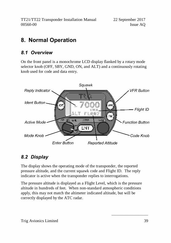
8.1 Overview
On the front panel is a monochrome LCD display flanked by a rotary mode selector knob (OFF, SBY, GND, ON, and ALT) and a continuously rotating knob used for code and data entry.
8.2 Display
The display shows the operating mode of the transponder, the reported pressure altitude, and the current squawk code and Flight ID. The reply indicator is active when the transponder replies to interrogations.
The pressure altitude is displayed as a Flight Level, which is the pressure altitude in hundreds of feet. When non-standard atmospheric conditions apply, this may not match the altimeter indicated altitude, but will be correctly displayed by the ATC radar.

TT21/TT22 Transponder Installation Manual 22 September 2017 00560-00 AQ
______________________
40 Trig Avionics Limited
8.3 Mode Selector Knob
The left hand knob controls the power to the transponder and the operating mode.
OFF Power is removed from the transponder.
SBY The transponder is on, but will not reply to any interrogations.
GND The transponder will respond to Mode S ground interrogations from surface movement radar.
ON The transponder will respond to all interrogations, but altitude reporting is suppressed.
ALT The transponder will respond to all interrogations.
When airborne, the transponder should always be set to ALT unless otherwise directed by Air Traffic Control. When you are taxiing on the ground, the transponder should be set to GND unless your installation includes a gear squat switch or GPS based automatic Air/Ground determination which will automatically select GND on landing. In these cases the mode switch can be left in ALT on the ground.
8.4 Push Buttons
IDT Press the IDT button when ATC instructs you to “Ident” or “Squawk Ident”. This activates the SPI pulse in the transponder replies for 18 seconds. IDT will appear in the display.
FN Pressing the FN button provides access to changing the Flight ID and the ADS-B position monitor and display brightness control.
VFR Pressing the VFR button sets the transponder to the pre-programmed conspicuity code. Pressing the button again restores the previous squawk code.
ENT The ENT button enters a digit in the code selector.

TT21/TT22 Transponder Installation Manual 22 September 2017 00560-00 Issue AQ
______________________
Trig Avionics Limited 41
8.5 Code Selector Knob
The right hand knob is used to set squawk codes and the Flight ID. The FN button selects which will be updated. Turning the knob will highlight the first digit on the display, and the digit can be changed as required. Press the ENT button to advance to the next digit. When ENT is pressed on the last digit, the new squawk code or Flight ID will replace the previous value. If the code entry is not completed within 7 seconds, the changes are ignored and the previous code restored.
1200 VFR code in the USA
7000 VFR code commonly used in Europe.
7500 Hijack code
7600 Loss of communications
7700 Emergency code
The Flight ID should correspond to the aircraft call sign entered on your flight plan. If no flight plan is active, the aircraft registration should be used as your Flight ID. Use only letters and digits. If the Flight ID is less than 8 characters long, entering a blank character will end it.
8.6 Altitude Encoder Warm Up
The built in altitude encoder uses a sensor that is temperature dependent. A small internal heater circuit keeps the sensor at the correct temperature. When the ambient temperature is below 0°C there may be a delay between switching on the transponder and seeing an altitude reported. In very cold weather this delay can be up to 5 minutes. You should always switch on the transponder (usually to GND mode) before taxiing to the runway, to ensure that the sensor is operating before you become airborne.
8.7 General Low Temperature Operation
The TT21/TT22 is certified to operate correctly down to -20°C, but at low temperatures the display may be impaired. On a cold day you may need to
TT21/TT22 Transponder Installation Manual 22 September 2017 00560-00 AQ
______________________
42 Trig Avionics Limited
wait for the cockpit to warm up to ensure normal operation.
8.8 ADS-B Monitor The ADS-B Monitor is only available on installations that include an ADS-B position source. The ADS-B Monitor provides a display of the position information that is being transmitted in ADS-B position reports. This can provide confirmation that the correct information is being transmitted, particularly where the GPS source is remote from the transponder. In the event that valid position information is NOT available from the GPS, the latitude and longitude display will be replaced by dashes; if no valid latitude and longitude is shown then ADS-B position information is NOT being transmitted.
8.9 Display Brightness Control
Pressing the FN button will allow access to change the display brightness. A bar will appear on the display with the title “Brightness” above the bar. Rotate the Code Knob to select the desired brightness level. Press FN to save the setting and return to the Squawk code display.
8.10 Warning Messages
If the transponder detects a problem, the screen will indicate WARNING and a brief statement of the problem. Depending on the nature of the problem, your transponder may not be replying to interrogations. Note the message on the screen and pass that information to your avionics maintenance organisation. Press ENT to clear the message; if the fault is still present the message will reappear.
8.11 Fault Annunciation
If the transponder detects a catastrophic internal failure, the screen will indicate FAULT and a brief statement of the problem. No replies will be made to interrogations when a fault has been detected.
Some FAULT indications can be recovered by switching the transponder off

TT21/TT22 Transponder Installation Manual 22 September 2017 00560-00 Issue AQ
______________________
Trig Avionics Limited 43
and back on again, although in all cases a FAULT code implies that there is a fault with the transponder or the installation. Note the FAULT message shown on the screen and pass that information to your avionics maintenance organisation.

TT21/TT22 Transponder Installation Manual 22 September 2017 00560-00 AQ
______________________
44 Trig Avionics Limited
9. Continued Airworthiness Other than for periodic functional checks required by the regulations, the TT21/TT22 Mode S transponder has been designed and manufactured to allow “on condition maintenance”. This means that there are no periodic service requirements necessary to maintain continued airworthiness, and no maintenance is required until the equipment does not properly perform its intended function. When service is required, a complete performance test should be accomplished following any repair action. Repairs should only be carried out in accordance with Trig Avionics Limited service procedures.

TT21/TT22 Transponder Installation Manual 22 September 2017 00560-00 Issue AQ
______________________
Trig Avionics Limited 45
10. Limited Warranty Trig Avionics Limited warrants our products to be free from defects in materials and workmanship for a period of two (2) years from the date of installation by an authorised dealer.
This warranty covers repair and/or replacement at our option, of any parts found to be defective, provided such defects in our opinion are due to faulty material or workmanship and are not caused by tampering, abuse, or normal wear.
All warranties are F.C.A.
Trig Avionics Limited Heriot Watt Research Park Riccarton, Currie, EH14 4AP
Trig Avionics will not accept or pay for any charges for warranty work performed outside our factory without prior written consent.
This warranty applies only to products in normal use. It does not apply to units or circuit boards defective due to improper installation, physical damage, tampering, lightning or other electrical discharge, units with altered serial numbers, or units repaired by unauthorised persons or in violation of Trig Avionics Limited service procedures.
Trig Avionics Limited assumes no responsibility for any consequential losses of any nature with respect to any products or services sold, rendered, or delivered.
TT21/TT22 Transponder Installation Manual 22 September 2017 00560-00 AQ
______________________
46 Trig Avionics Limited
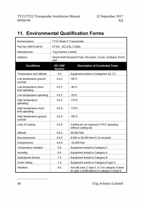
11. Environmental Qualification Forms Nomenclature: TT21 Mode S Transponder
Part No: 00675-00-01 ETSO: 2C112b, C166a
Manufacturer: Trig Avionics Limited
Address: Heriot Watt Research Park, Riccarton, Currie, Scotland, EH14 4AP
Conditions DO-160F Section
Description of Conducted Tests
Temperature and Altitude 4.0 Equipment tested to Categories A2, C1
Low temperature ground survival
4.5.1 -55°C
Low temperature short-time operating
4.5.1 -40°C
Low temperature operating 4.5.2 -20°C
High temperature operating
4.5.4 +70°C
High temperature short-time operating
4.5.3 +70°C
High temperature ground survival
4.5.3 +85°C
Loss of Cooling 4.5.5 Cooling air not required (+70°C operating without cooling air)
Altitude 4.6.1 35,000 feet
Decompression 4.6.2 8,000 to 35,000 feet in 15 seconds
Overpressure 4.6.3 -15,000 feet
Temperature Variation 5.0 Equipment tested to Category C
Humidity 6.0 Equipment tested to Category A
Operational Shocks 7.2 Equipment tested to Category B
Crash Safety 7.3 Equipment tested to Category B type 5
Vibration 8.0 Aircraft zone 2; type 3, 4, 5 to category S level M, type 1 (Helicopters) to category U level G

TT21/TT22 Transponder Installation Manual 22 September 2017 00560-00 Issue AQ
______________________
Trig Avionics Limited 47
Explosion 9.0 Equipment identified as Category X – no test required
Waterproofness 10.0 Equipment identified as Category X – no test required
Fluids Susceptibility 11.0 Equipment identified as Category X – no test required
Sand and Dust 12.0 Equipment identified as Category X – no test required
Fungus 13.0 Equipment identified as Category X – no test required
Salt Spray 14.0 Equipment identified as Category X – no test required
Magnetic Effect 15.0 Equipment tested to Category Z
Power Input 16.0 Equipment tested to Category BX
Voltage Spike 17.0 Equipment tested to Category B
Audio frequency conducted susceptibility
18.0 Equipment tested to Category B
Induced signal susceptibility
19.0 Equipment tested to Category AC
Radio frequency susceptibility
20.0 Equipment tested to Category TT
Radio frequency emission 21.0 Equipment tested to Category B
Lightning induced transient susceptibility
22.0 Equipment identified as Category XXXX – no test required
Lightning direct effects 23.0 Equipment identified as Category X – no test required
Icing 24.0 Equipment identified as Category X – no test required
Electrostatic Discharge 25.0 Equipment identified as Category X – no test required
Fire, Flammability 26.0 Equipment identified as Category C
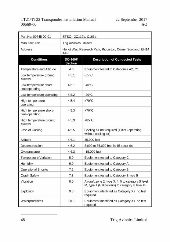
Nomenclature: TT22 Mode S Transponder
TT21/TT22 Transponder Installation Manual 22 September 2017 00560-00 AQ
______________________
48 Trig Avionics Limited
Part No: 00745-00-01 ETSO: 2C112b, C166a
Manufacturer: Trig Avionics Limited
Address: Heriot Watt Research Park, Riccarton, Currie, Scotland, EH14 4AP
Conditions DO-160F Section
Description of Conducted Tests
Temperature and Altitude 4.0 Equipment tested to Categories A2, C1
Low temperature ground survival
4.5.1 -55°C
Low temperature short-time operating
4.5.1 -40°C
Low temperature operating 4.5.2 -20°C
High temperature operating
4.5.4 +70°C
High temperature short-time operating
4.5.3 +70°C
High temperature ground survival
4.5.3 +85°C
Loss of Cooling 4.5.5 Cooling air not required (+70°C operating without cooling air)
Altitude 4.6.1 35,000 feet
Decompression 4.6.2 8,000 to 35,000 feet in 15 seconds
Overpressure 4.6.3 -15,000 feet
Temperature Variation 5.0 Equipment tested to Category C
Humidity 6.0 Equipment tested to Category A
Operational Shocks 7.2 Equipment tested to Category B
Crash Safety 7.3 Equipment tested to Category B type 5
Vibration 8.0 Aircraft zone 2; type 3, 4, 5 to category S level M, type 1 (Helicopters) to category U level G
Explosion 9.0 Equipment identified as Category X – no test required
Waterproofness 10.0 Equipment identified as Category X – no test required

TT21/TT22 Transponder Installation Manual 22 September 2017 00560-00 Issue AQ
______________________
Trig Avionics Limited 49
Fluids Susceptibility 11.0 Equipment identified as Category X – no test required
Sand and Dust 12.0 Equipment identified as Category X – no test required
Fungus 13.0 Equipment identified as Category X – no test required
Salt Spray 14.0 Equipment identified as Category X – no test required
Magnetic Effect 15.0 Equipment tested to Category Z
Power Input 16.0 Equipment tested to Category BX
Voltage Spike 17.0 Equipment tested to Category B
Audio frequency conducted susceptibility
18.0 Equipment tested to Category B
Induced signal susceptibility
19.0 Equipment tested to Category AC
Radio frequency susceptibility
20.0 Equipment tested to Category TT
Radio frequency emission 21.0 Equipment tested to Category B
Lightning induced transient susceptibility
22.0 Equipment identified as Category XXXX – no test required
Lightning direct effects 23.0 Equipment identified as Category X – no test required
Icing 24.0 Equipment identified as Category X – no test required
Electrostatic Discharge 25.0 Equipment identified as Category X – no test required
Fire, Flammability 26.0 Equipment identified as Category C
Nomenclature TC20 Mode S Controller
Part Number: 00649-00 ETSO: 2C112b, C88a
Manufacturer Trig Avionics Limited

TT21/TT22 Transponder Installation Manual 22 September 2017 00560-00 AQ
______________________
50 Trig Avionics Limited
Address Heriot Watt Research Park, Riccarton, Currie, Scotland, EH14 4AP
Conditions DO-160F Section
Description of Conducted Tests
Temperature and Altitude 4.0 Equipment tested to Categories A4, C4
Low temperature ground survival
4.5.1 -55°C
Low temperature short-time operating
4.5.1 -25°C
Low temperature operating 4.5.2 -20°C
High temperature operating
4.5.3 +55°C
High temperature short-time operating
4.5.3 +70°C
High temperature ground survival
4.5.3 +85°C
Loss of Cooling 4.5.5 Cooling air not required (+70°C operating without cooling air)
Altitude 4.6.1 35,000 feet
Decompression 4.6.2 8,000 to 35,000 feet in 15 seconds
Overpressure 4.6.3 -15,000 feet
Temperature Variation 5.0 Equipment tested to Category A
Humidity 6.0 Equipment tested to Category A
Operational Shocks 7.2 Equipment tested to Category B
Crash Safety 7.3 Equipment tested to Category B type 5
Vibration 8.0 Aircraft zone 2; type 3, 4, 5 to category S level M, type 1 (Helicopters) to category U level G
Explosion 9.0 Equipment identified as Category X – no test required
Waterproofness 10.0 Equipment tested to Category W (front face only)
Fluids Susceptibility 11.0 Equipment identified as Category X – no test required
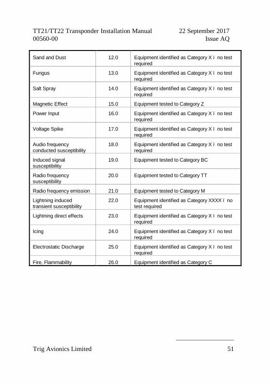
TT21/TT22 Transponder Installation Manual 22 September 2017 00560-00 Issue AQ
______________________
Trig Avionics Limited 51
Sand and Dust 12.0 Equipment identified as Category X – no test required
Fungus 13.0 Equipment identified as Category X – no test required
Salt Spray 14.0 Equipment identified as Category X – no test required
Magnetic Effect 15.0 Equipment tested to Category Z
Power Input 16.0 Equipment identified as Category X – no test required
Voltage Spike 17.0 Equipment identified as Category X – no test required
Audio frequency conducted susceptibility
18.0 Equipment identified as Category X – no test required
Induced signal susceptibility
19.0 Equipment tested to Category BC
Radio frequency susceptibility
20.0 Equipment tested to Category TT
Radio frequency emission 21.0 Equipment tested to Category M
Lightning induced transient susceptibility
22.0 Equipment identified as Category XXXX – no test required
Lightning direct effects 23.0 Equipment identified as Category X – no test required
Icing 24.0 Equipment identified as Category X – no test required
Electrostatic Discharge 25.0 Equipment identified as Category X – no test required
Fire, Flammability 26.0 Equipment identified as Category C

TT21/TT22 Transponder Installation Manual 22 September 2017 00560-00 AQ
______________________
52 Trig Avionics Limited
12. ADS-B Compliance TT21/TT22 transponders include support for Extended Squitter ADS-B out. The TT21/TT22 with software version 2.1 or higher is a DO-260B compliant broadcast participant.
12.1 ADS-B Parameters Supported
The following table summarises the ADS-B parameters that are transmitted by the TT21/TT22 transponder when connected to an appropriate GPS receiver.
Parameter BDS Register
SPI 0,5
Emergency Indicator 0,5
Barometric Altitude 0,5
Quality Indicator (NIC) 0,5
Airborne Position Latitude 0,5
Longitude 0,5
Quality Indicator (NIC) 0,6
Surface Position Latitude 0,6
Longitude 0,6
Surface Ground Speed 0,6
Surface Ground Track 0,6
Aircraft Identification 0,8
Airborne Ground Velocity 0,9
Geometric to Barometric altitude difference 0,9
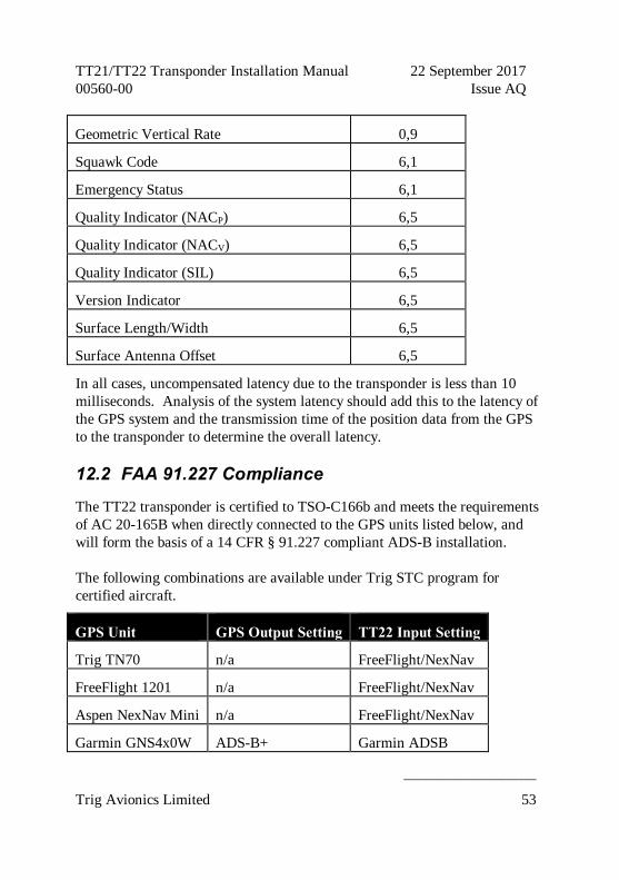
TT21/TT22 Transponder Installation Manual 22 September 2017 00560-00 Issue AQ
______________________
Trig Avionics Limited 53
Geometric Vertical Rate 0,9
Squawk Code 6,1
Emergency Status 6,1
Quality Indicator (NACP) 6,5
Quality Indicator (NACV) 6,5
Quality Indicator (SIL) 6,5
Version Indicator 6,5
Surface Length/Width 6,5
Surface Antenna Offset 6,5
In all cases, uncompensated latency due to the transponder is less than 10 milliseconds. Analysis of the system latency should add this to the latency of the GPS system and the transmission time of the position data from the GPS to the transponder to determine the overall latency.
12.2 FAA 91.227 Compliance
The TT22 transponder is certified to TSO-C166b and meets the requirements of AC 20-165B when directly connected to the GPS units listed below, and will form the basis of a 14 CFR § 91.227 compliant ADS-B installation.
The following combinations are available under Trig STC program for certified aircraft.
GPS Unit GPS Output Setting TT22 Input Setting
Trig TN70 n/a FreeFlight/NexNav
FreeFlight 1201 n/a FreeFlight/NexNav
Aspen NexNav Mini n/a FreeFlight/NexNav
Garmin GNS4x0W ADS-B+ Garmin ADSB

TT21/TT22 Transponder Installation Manual 22 September 2017 00560-00 AQ
______________________
54 Trig Avionics Limited
Garmin GNS5x0W ADS-B+ Garmin ADSB
Garmin GTN6xx ADS-B+ Garmin ADSB
Garmin GTN7xx ADS-B+ Garmin ADSB
In addition, where an STC is not required, for example Experimental aircraft, the following combinations are also supported and will form the basis of a 14 CFR § 91.227 compliant ADS-B installation.
GPS Unit GPS Output Setting TT22 Input Setting
Trig TN72 n/a Trig TN72 SIL=3
Avidyne IFD 4xx ADS-B (Avi) Trig ADSB
Avidyne IFD 5xx ADS-B (Avi) Trig ADSB
Garmin GPS 20A n/a Garmin ADSB
For installations seeking certification to 91.227 or other applicable standards, additional compliance information is available on request from Trig Avionics Limited.
12.3 CS-ACNS Compliance
The TT21 or TT22 transponder can be connected to the following GPS units to form the basis of a CS-ACNS compliant ADS-B installation:
GPS Unit GPS Output Setting TT22 Input Setting
Trig TN70 n/a FreeFlight/NexNav
FreeFlight 1201 n/a FreeFlight/NexNav
Aspen NexNav Mini n/a FreeFlight/NexNav
Avidyne IFD 4xx ADS-B (Avi) Trig ADSB
Avidyne IFD 5xx ADS-B (Avi) Trig ADSB
Garmin GNS4x0W ADS-B or ADS-B+ Garmin ADSB

TT21/TT22 Transponder Installation Manual 22 September 2017 00560-00 Issue AQ
______________________
Trig Avionics Limited 55
Garmin GNS5x0W ADS-B or ADS-B+ Garmin ADSB
Garmin GTN6xx ADS-B+ Garmin ADSB
Garmin GTN7xx ADS-B+ Garmin ADSB
Garmin GPS 20A n/a Garmin ADSB
For installations seeking certification to CS-ACNS or other applicable standards, additional compliance information is available on request from Trig Avionics Limited.
12.4 TSO C199 TABS Compliance
The TT21 and TT22 transponders are TSO C166b compliant ADS-B transmitters. When connected to an appropriate TSO C199 Class B GPS position source all transmitted ADS-B data complies with section A1.2.5 of TSO C199.
The Traffic Awareness Beacon System (TABS) is intended for voluntary equipage on aircraft exempted from carrying Automatic Dependent Surveillance - Broadcast (ADS-B) equipment, such as gliders, balloons and aircraft without electrical systems. TABS devices provide interoperability with airborne and ground traffic receivers, but do not meet the ADS-B requirements defined in 14 CFR § 91.227.
12.5 Automatic Air/Ground Determination
The TT21/22 can report ADS-B surface and airborne messages. The squat switch input is designed to be used with an automatic air/ground switching device as defined in section 5.6.7. If no squat switch input is available, the transponder can automatically determine the air/ground status from the GPS input.
12.6 ADS-B Support
If you require additional information and data to support an ADS-B installation then please contact [email protected].

TT21/TT22 Transponder Installation Manual 22 September 2017 00560-00 AQ
______________________
56 Trig Avionics Limited
13. Installation Drawings
13.1 Mounting tray fixing and overall dimensions
All dimensions in millimetres
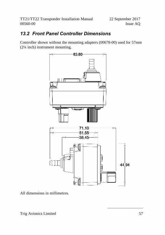
TT21/TT22 Transponder Installation Manual 22 September 2017 00560-00 Issue AQ
______________________
Trig Avionics Limited 57
13.2 Front Panel Controller Dimensions
Controller shown without the mounting adapters (00678-00) used for 57mm (2¼ inch) instrument mounting.
All dimensions in millimetres.
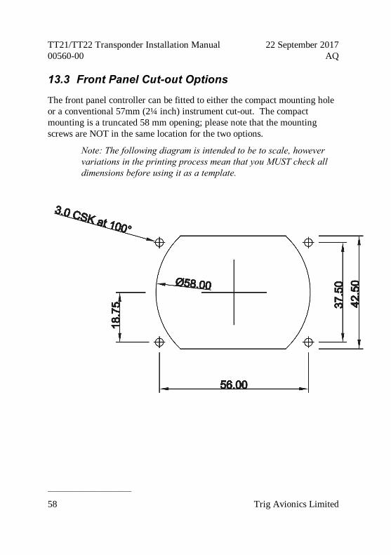
TT21/TT22 Transponder Installation Manual 22 September 2017 00560-00 AQ
______________________
58 Trig Avionics Limited
13.3 Front Panel Cut-out Options
The front panel controller can be fitted to either the compact mounting hole or a conventional 57mm (2¼ inch) instrument cut-out. The compact mounting is a truncated 58 mm opening; please note that the mounting screws are NOT in the same location for the two options.
Note: The following diagram is intended to be to scale, however variations in the printing process mean that you MUST check all dimensions before using it as a template.

TT21/TT22 Transponder Installation Manual 22 September 2017 00560-00 Issue AQ
______________________
Trig Avionics Limited 59
Note: The following diagram is intended to be to scale, however variations in the printing process mean that you MUST check all dimensions before using it as a template.
All dimensions in millimetres.
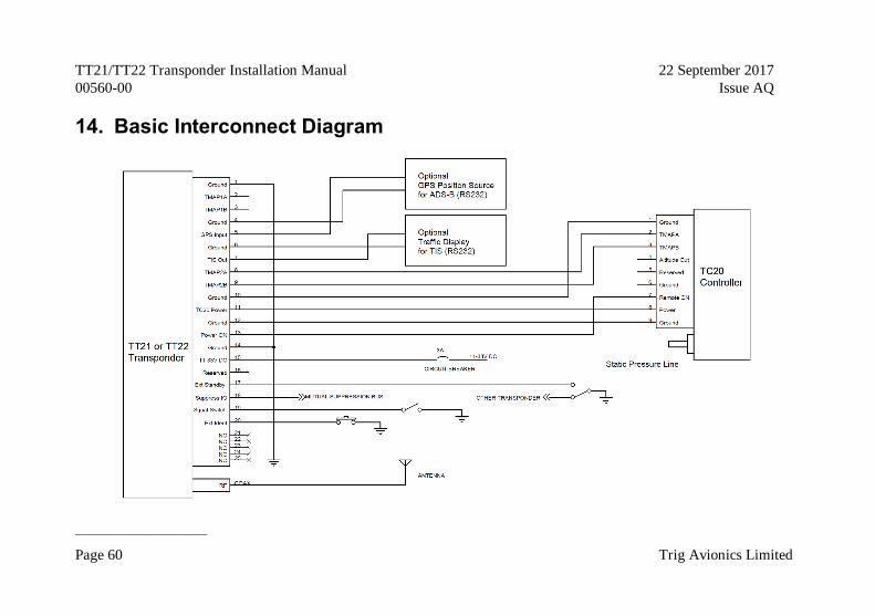
TT21/TT22 Transponder Installation Manual 22 September 2017 00560-00 Issue AQ
______________________
Page 60 Trig Avionics Limited
14. Basic Interconnect Diagram

Trig Avionics Limited
This page intentionally left blank


![TRANSPONDER BYPASS: SENTRY KEY [INSTALLATION GUIDE] · Transponder Bypass: RF override via induction w/ loop antenna (transponder incl. no key required). This transponder bypass kit](https://static.fdocuments.us/doc/165x107/5f51bec37e825f53705baf2b/transponder-bypass-sentry-key-installation-guide-transponder-bypass-rf-override.jpg)