TRUETZSCHLER – TOYOTA Combing · 2018-04-07 · 8 Combing The new Truetzschler-Toyota Superlap...
26
TRUETZSCHLER – TOYOTA Combing
Transcript of TRUETZSCHLER – TOYOTA Combing · 2018-04-07 · 8 Combing The new Truetzschler-Toyota Superlap...

TRUETZSCHLER – TOYOTA
Combing
Combing4
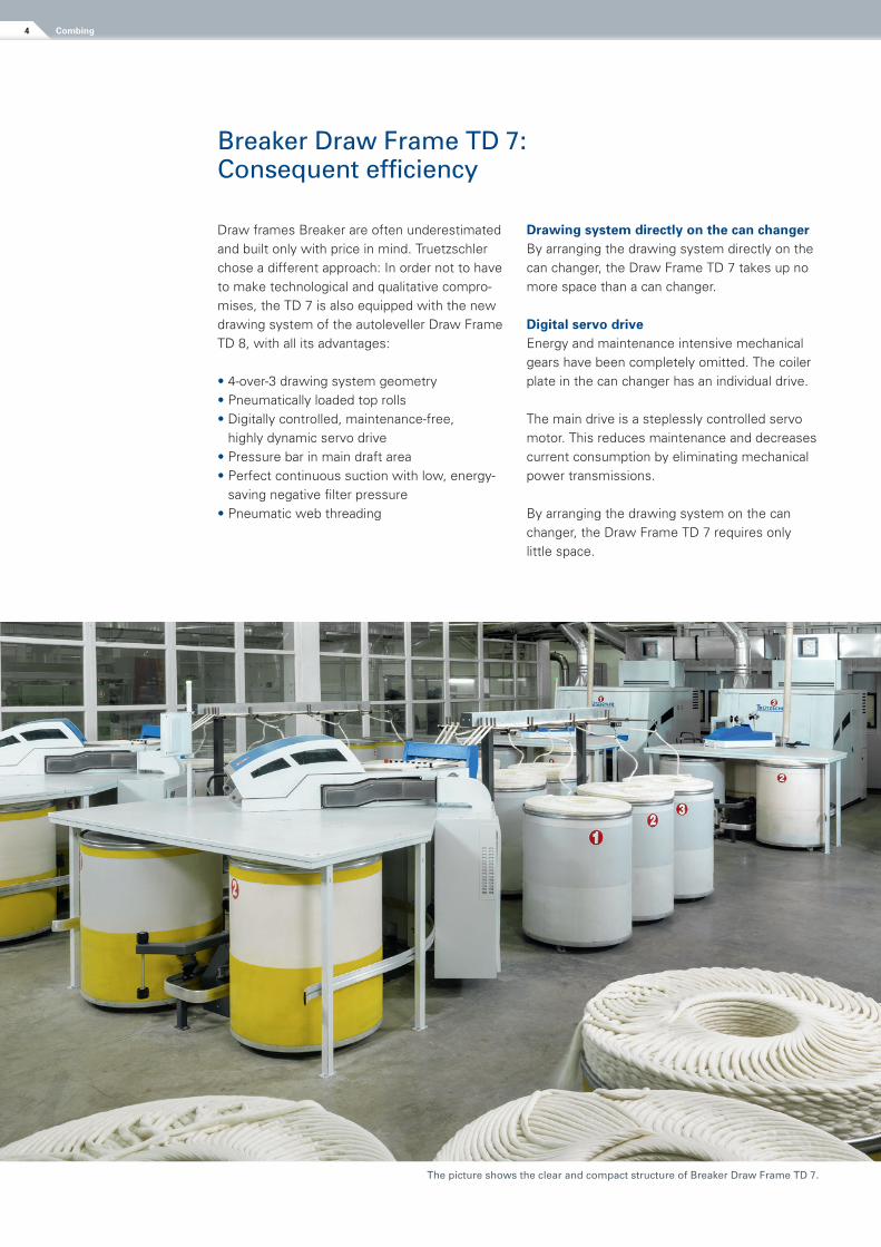
Breaker Draw Frame TD 7: Consequent efficiency
Draw frames Breaker are often under estimated and built only with price in mind. Truetzschler chose a different approach: In order not to have to make technological and qualitative compro-mises, the TD 7 is also equipped with the new drawing system of the autoleveller Draw Frame TD 8, with all its advantages:
• 4-over-3 drawing system geometry• Pneumatically loaded top rolls• Digitally controlled, maintenance-free,
highly dynamic servo drive• Pressure bar in main draft area• Perfect continuous suction with low, energy-
saving negative filter pressure• Pneumatic web threading
Drawing system directly on the can changer By arranging the drawing system directly on the can changer, the Draw Frame TD 7 takes up no more space than a can changer.
Digital servo drive Energy and maintenance intensive mechanical gears have been completely omitted. The coiler plate in the can changer has an individual drive.
The main drive is a steplessly controlled servo motor. This reduces maintenance and decreases current consumption by eliminating mechanical power transmissions.
By arranging the drawing system on the can changer, the Draw Frame TD 7 requires only little space.
The picture shows the clear and compact structure of Breaker Draw Frame TD 7.
5Combing
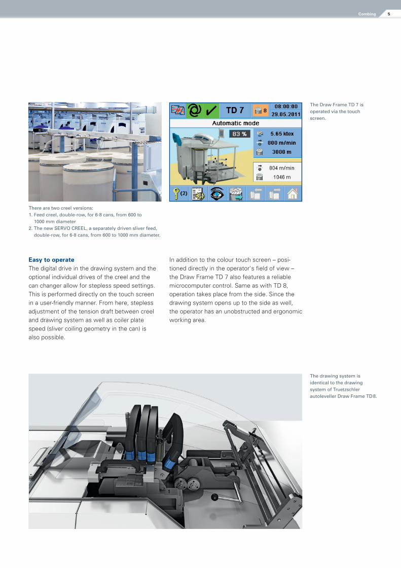
The drawing system is identical to the drawing system of Truetzschler autoleveller Draw Frame TD 8.
There are two creel versions:1. Feed creel, double-row, for 6-8 cans, from 600 to
1000 mm diameter2. The new SERVO CREEL, a separately driven sliver feed,
double-row, for 6-8 cans, from 600 to 1000 mm diameter.
The Draw Frame TD 7 is operated via the touch screen.
Easy to operate The digital drive in the drawing system and the optional individual drives of the creel and the can changer allow for stepless speed settings. This is performed directly on the touch screen in a user-friendly manner. From here, stepless adjustment of the tension draft between creel and drawing system as well as coiler plate speed (sliver coiling geometry in the can) is also possible.
In addition to the colour touch screen – posi-tioned directly in the operator's field of view – the Draw Frame TD 7 also features a reliable microcomputer control. Same as with TD 8, operation takes place from the side. Since the drawing system opens up to the side as well, the operator has an unobstructed and ergonomic working area.
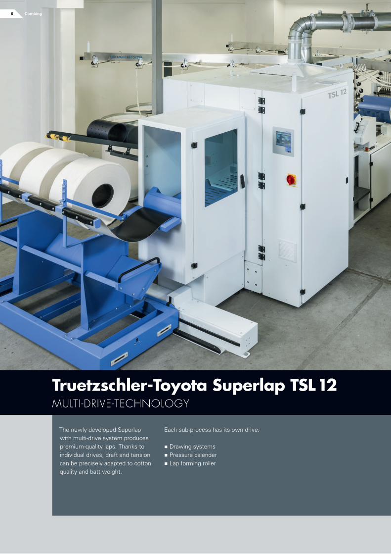
The newly developed Superlap with multi-drive system produces premium-quality laps. Thanks to individual drives, draft and tension can be precisely adapted to cotton quality and batt weight.
Each sub-process has its own drive.
n Drawing systemsn Pressure calendern Lap forming roller
Truetzschler-Toyota Superlap TSL 12 Multi-Drive-technology
6 Combing
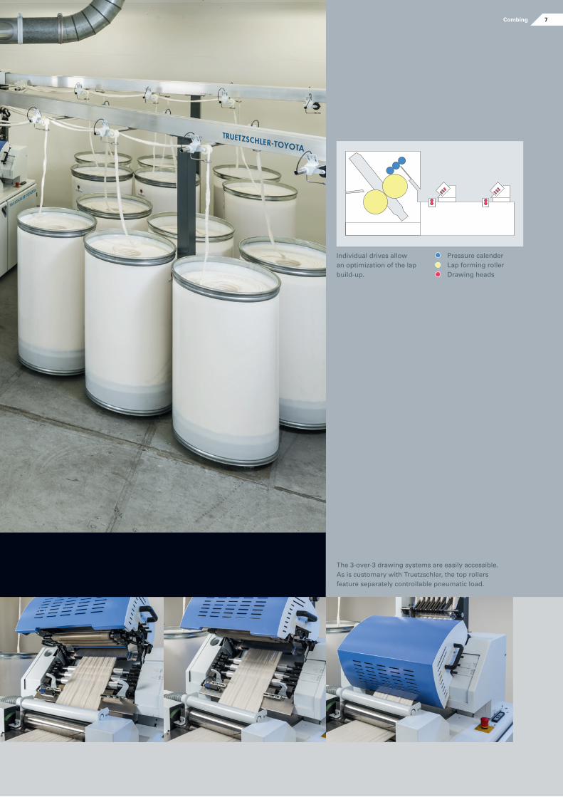
The 3-over-3 drawing systems are easily accessible. As is customary with Truetzschler, the top rollers feature separately controllable pneumatic load.
Pressure calenderLap forming rollerDrawing heads
Individual drives allow an optimization of the lap build-up.
7Combing
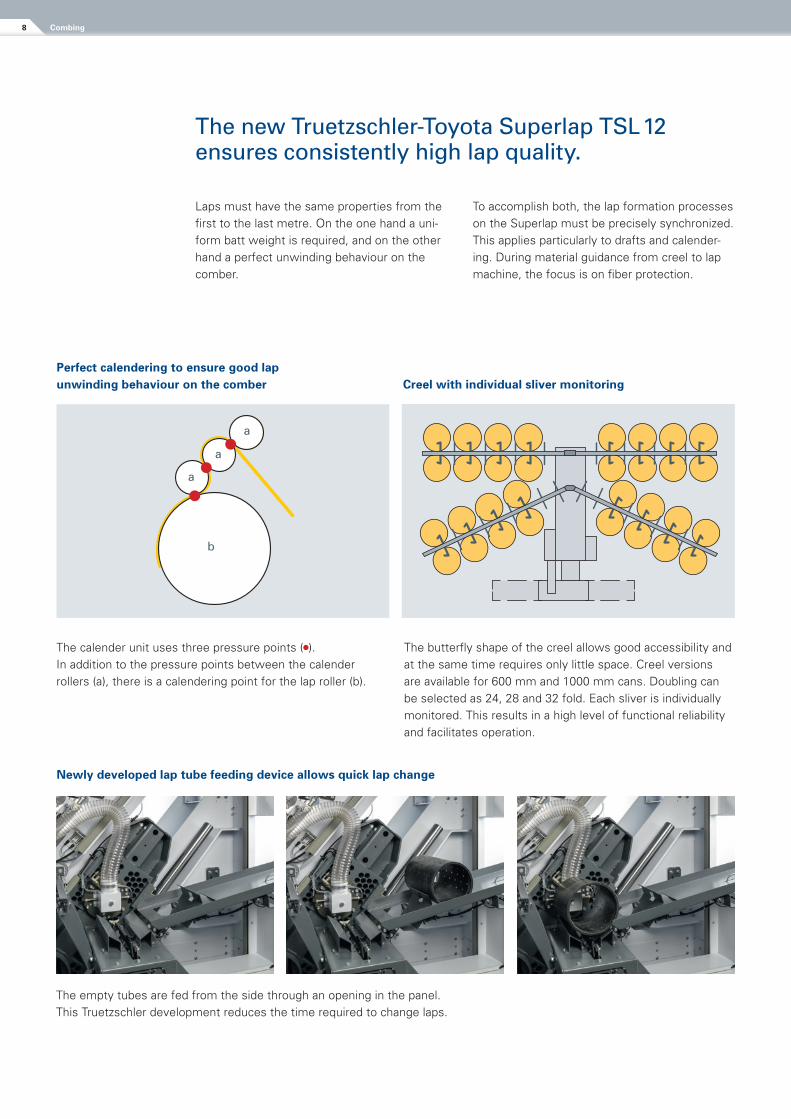
Perfect calendering to ensure good lap unwinding behaviour on the comber Creel with individual sliver monitoring
Newly developed lap tube feeding device allows quick lap change
The calender unit uses three pressure points ( ). In addition to the pressure points between the calender rollers (a), there is a calendering point for the lap roller (b).
The butterfly shape of the creel allows good accessibility and at the same time requires only little space. Creel versions are available for 600 mm and 1000 mm cans. Doubling can be selected as 24, 28 and 32 fold. Each sliver is individually monitored. This results in a high level of functional reliability and facilitates operation.
The empty tubes are fed from the side through an opening in the panel. This Truetzschler development reduces the time required to change laps.
•••
b
a
a
a
Combing8
The new Truetzschler-Toyota Superlap TSL 12 ensures consistently high lap quality.
Laps must have the same properties from the first to the last metre. On the one hand a uni-form batt weight is required, and on the other hand a perfect unwinding behaviour on the comber.
To accomplish both, the lap formation processes on the Superlap must be precisely synchronized. This applies particularly to drafts and calender-ing. During material guidance from creel to lap machine, the focus is on fiber protection.
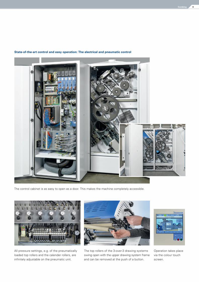
State-of-the-art control and easy operation: The electrical and pneumatic control
Operation takes place via the colour touch screen.
All pressure settings, e.g. of the pneumatically loaded top rollers and the calender rollers, are infinitely adjustable on the pneumatic unit.
The top rollers of the 3-over-3 drawing systems swing open with the upper drawing system frame and can be removed at the push of a button.
The control cabinet is as easy to open as a door. This makes the machine completely accessible.
9Combing
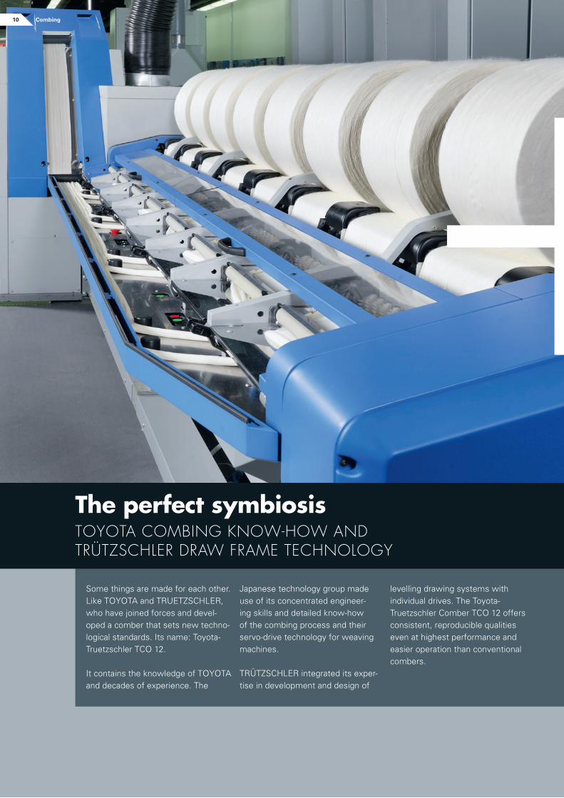
Some things are made for each other. Like TOYOTA and TRUETZSCHLER, who have joined forces and devel-oped a comber that sets new techno-logical standards. Its name: Toyota-Truetzschler TCO 12.
It contains the knowledge of TOYOTA and decades of experience. The
levelling drawing systems with individual drives. The Toyota-Truetzschler Comber TCO 12 offers consistent, reproducible qualities even at highest performance and easier operation than conventional combers.
Japanese technology group made use of its concentrated engineer-ing skills and detailed know-how of the combing process and their servo-drive technology for weaving machines.
TRÜTZSCHLER integrated its exper-tise in development and design of
The perfect symbiosis toyotA coMbing know-how AnDtrÜtZSchler DrAw frAMe technology
+10 Combing
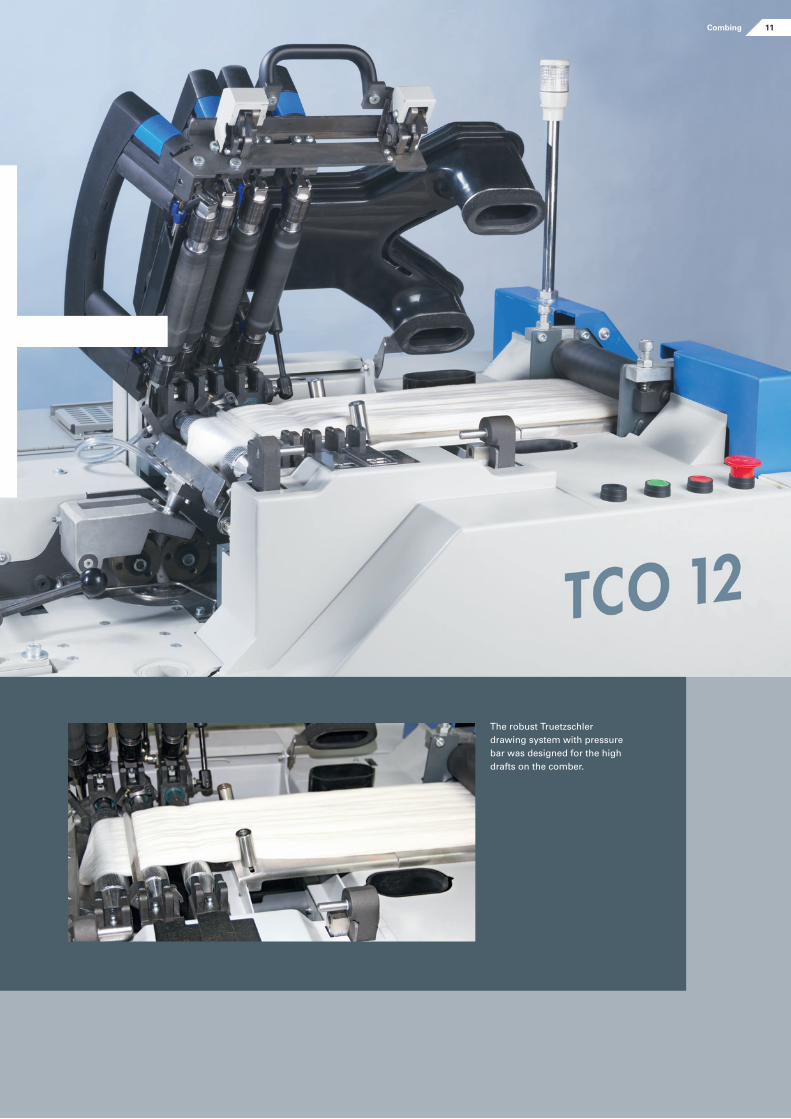
The robust Truetzschler drawing system with pressure bar was designed for the high drafts on the comber.
+11Combing
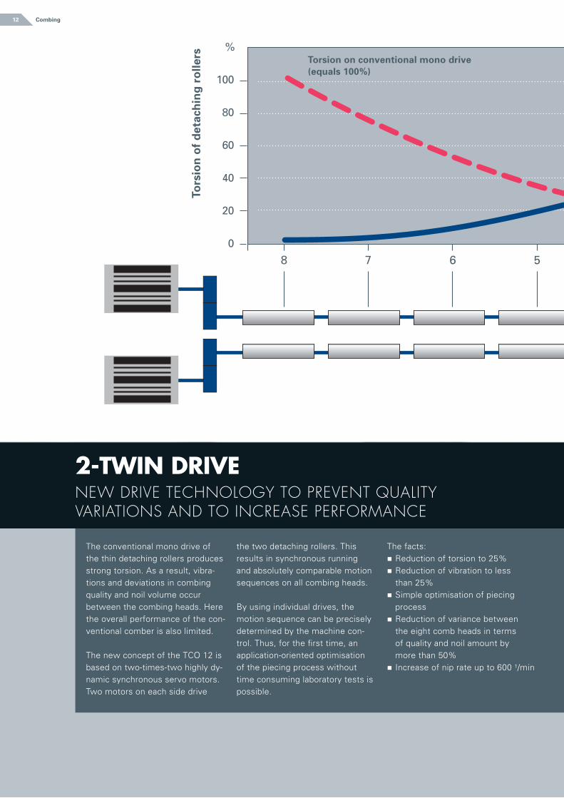
The conventional mono drive of the thin detaching rollers produces strong torsion. As a result, vibra-tions and deviations in combing quality and noil volume occur be tween the combing heads. Here the overall performance of the con-ventional comber is also limited. The new concept of the TCO 12 is based on two-times-two highly dy-namic synchronous servo motors. Two motors on each side drive
the two detaching rollers. This results in synchronous running and absolutely comparable motion sequences on all combing heads.
By using individual drives, the motion sequence can be precisely determined by the machine con-trol. Thus, for the first time, an application-oriented optimisation of the piecing process without time consuming laboratory tests is possible.
The facts:n Reduction of torsion to 25%n Reduction of vibration to less
than 25%n Simple optimisation of piecing
processn Reduction of variance between
the eight comb heads in terms of quality and noil amount by more than 50%
n Increase of nip rate up to 600 ¹/min
2-Twin Drive new Drive technology to prevent quAlity vAriAtionS AnD to increASe perforMAnce
12 Combing12
8 7 6 5 4 3 2 1
%
100
80
60
40
20
0
Torsion on conventional mono drive (equals 100%)
Tors
ion
of
det
ach
ing
ro
llers
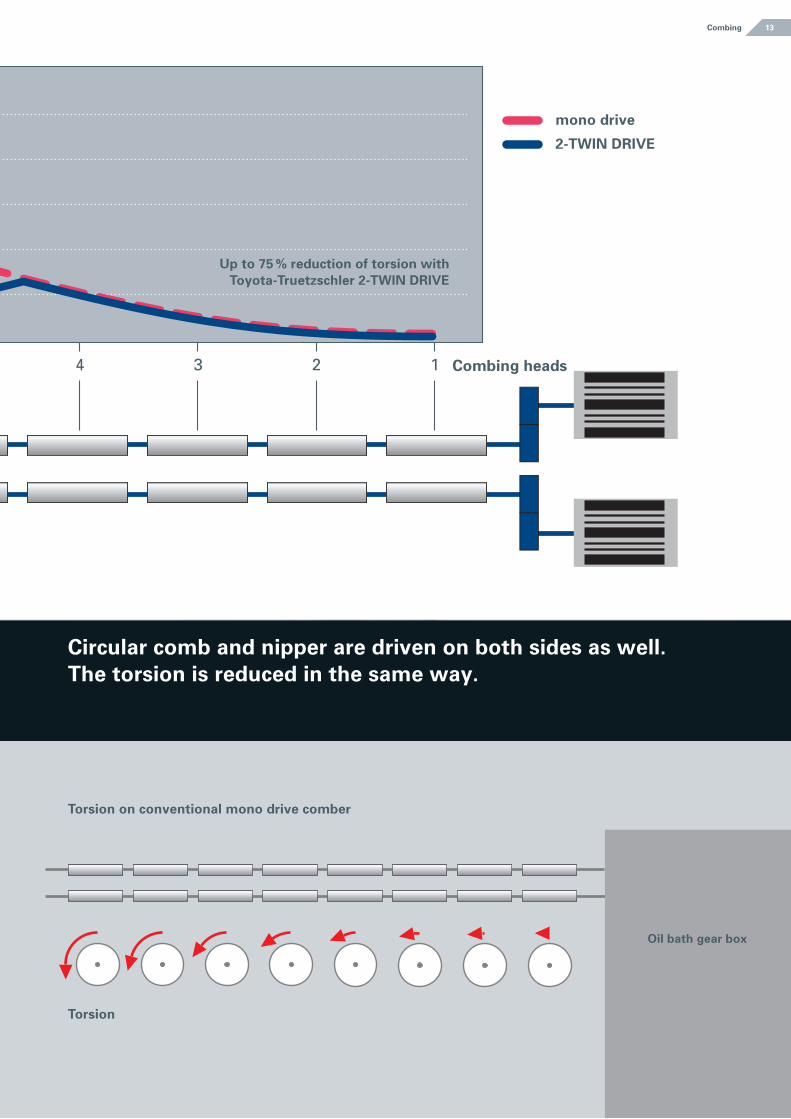
Circular comb and nipper are driven on both sides as well. The torsion is reduced in the same way.
Combing
8 7 6 5 4 3 2 1
Up to 75 % reduction of torsion with Toyota-Truetzschler 2-TwiN DrivE
Combing heads
Torsion on conventional mono drive comber
Torsion
Oil bath gear box
mono drive
2-TwiN DrivE
13
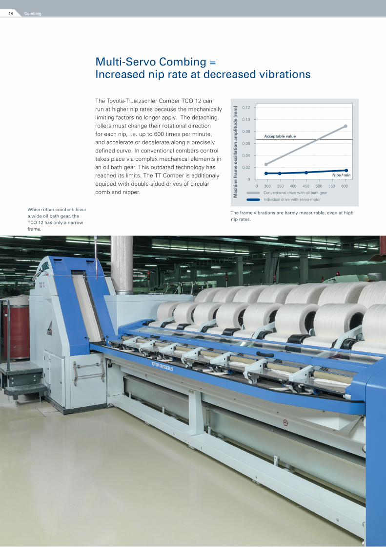
Multi-Servo Combing = Increased nip rate at decreased vibrations
The Toyota-Truetzschler Comber TCO 12 can run at higher nip rates because the mechanically limiting factors no longer apply. The detaching rollers must change their rotational direction for each nip, i.e. up to 600 times per minute, and accelerate or decelerate along a precisely defined curve. In conventional combers control takes place via complex mechanical elements in an oil bath gear. This outdated technology has reached its limits. The TT Comber is additionaly equiped with double-sided drives of circular comb and nipper.
The frame vibrations are barely measurable, even at high nip rates.
Where other combers have a wide oil bath gear, the TCO 12 has only a narrow frame.
0,12
0,10
0,08
0,06
0,04
0,02
0
0 300 350 400 450 500 550 600
Mac
hin
e fr
ame
osc
illat
ion
am
plit
ud
e [m
m]
Nips / min
Acceptable value
Conventional drive with oil bath gear
Individual drive with servo-motor
Combing14
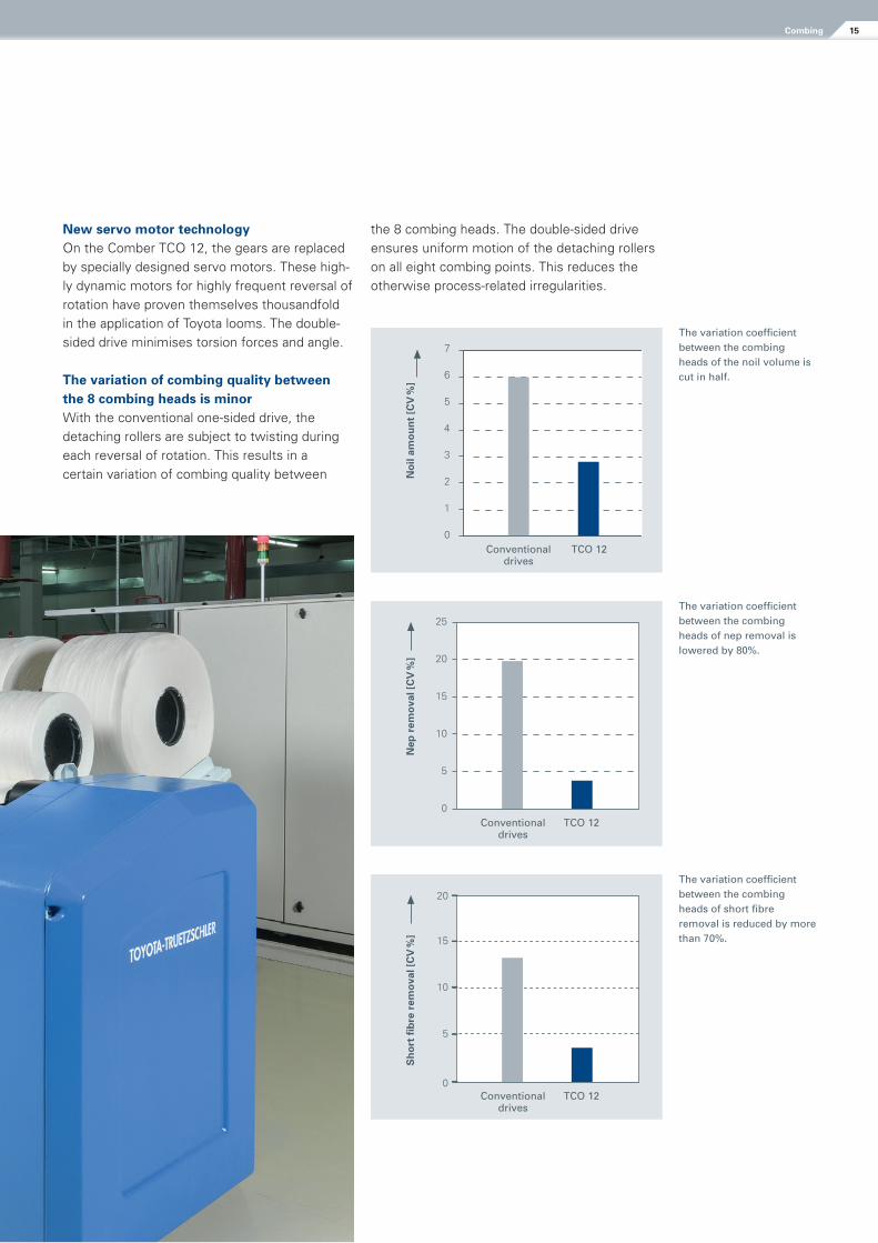
The variation coefficient between the combing heads of the noil volume is cut in half.
0
1
2
3
4
5
6
7
Conventionaldrives
TCO 12
No
il am
ou
nt
[Cv
%]
New servo motor technology On the Comber TCO 12, the gears are replaced by specially designed servo motors. These high-ly dynamic motors for highly frequent reversal of rotation have proven themselves thousandfold in the application of Toyota looms. The double-sided drive minimises torsion forces and angle.
The variation of combing quality between the 8 combing heads is minorWith the conventional one-sided drive, the detaching rollers are subject to twisting during each reversal of rotation. This results in a certain variation of combing quality between
the 8 combing heads. The double-sided drive ensures uniform motion of the detaching rollers on all eight combing points. This reduces the otherwise process-related irregularities.
The variation coefficient between the combing heads of nep removal is lowered by 80%.
The variation coefficient between the combing heads of short fibre removal is reduced by more than 70%.
0
5
10
15
20
25
Conventionaldrives
TCO 12
Nep
rem
ova
l [C
v %
]
0
5
10
15
20
Conventionaldrives
TCO 12
Sh
ort
fib
re r
emo
val [
Cv
%]
15Combing
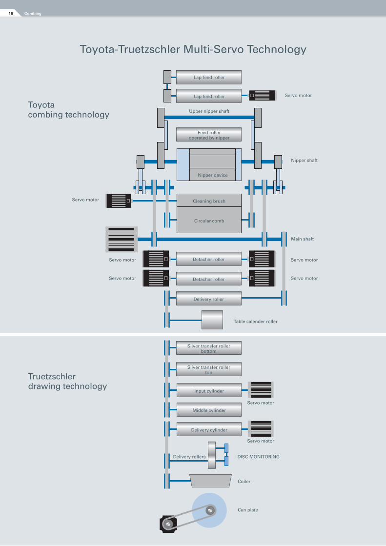
Toyota-Truetzschler Multi-Servo Technology
Truetzschlerdrawing technology
Toyotacombing technology
Delivery cylinder
Middle cylinder
Input cylinder
Sliver transfer roller top
Sliver transfer roller bottom
Delivery roller
Detacher roller
Detacher roller
Circular comb
Cleaning brush
Feed roller operated by nipper
Upper nipper shaft
Lap feed roller
Lap feed roller
Nipper device
Table calender roller
Can plate
Coiler
DISC MONITORING
Servo motor
Servo motor
Servo motor Servo motor
Nipper shaft
Main shaft
Servo motor Servo motor
Servo motor
Servo motor
Delivery rollers
Combing16
Drawing system technology with high performance levelling draw frame
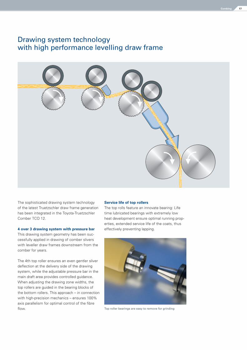
The sophisticated drawing system technology of the latest Truetzschler draw frame generation has been integrated in the Toyota-Truetzschler Comber TCO 12.
4 over 3 drawing system with pressure barThis drawing system geometry has been suc-cessfully applied in drawing of comber slivers with leveller draw frames downstream from the comber for years.
The 4th top roller ensures an even gentler sliver deflection at the delivery side of the drawing system, while the adjustable pressure bar in the main draft area provides controlled guidance. When adjusting the drawing zone widths, the top rollers are guided in the bearing blocks of the bottom rollers. This approach – in connection with high-precision mechanics – ensures 100% axis parallelism for optimal control of the fibre flow. Top roller bearings are easy to remove for grinding
Service life of top rollersThe top rolls feature an innovate bearing: Life time lubricated bearings with extremely low heat development ensure optimal running prop-erties, extended service life of the coats, thus effectively preventing lapping.
17Combing
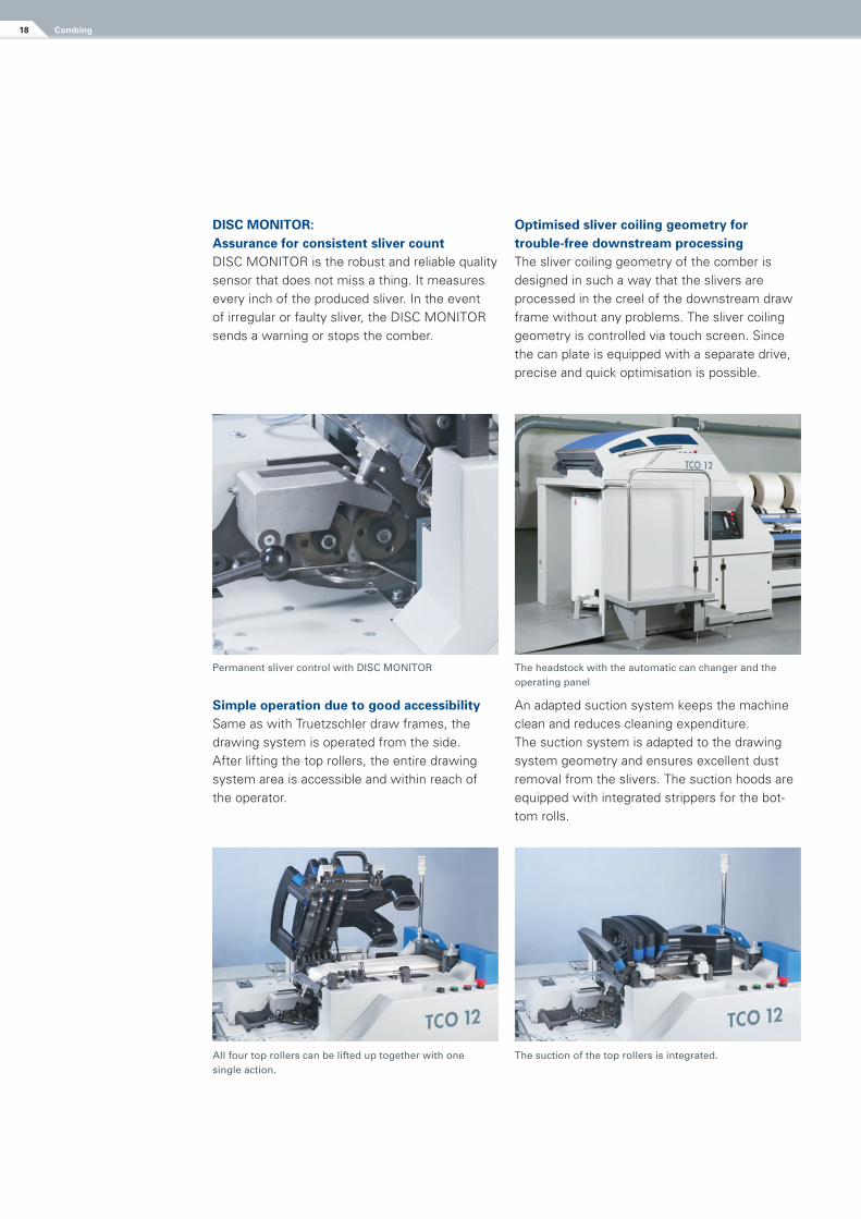
Permanent sliver control with DISC MONITOR
All four top rollers can be lifted up together with one single action.
The suction of the top rollers is integrated.
The headstock with the automatic can changer and the operating panel
DiSC MONiTOr: Assurance for consistent sliver countDISC MONITOR is the robust and reliable quality sensor that does not miss a thing. It measures every inch of the produced sliver. In the event of irregular or faulty sliver, the DISC MONITOR sends a warning or stops the comber.
Simple operation due to good accessibilitySame as with Truetzschler draw frames, the drawing system is operated from the side. After lifting the top rollers, the entire drawing system area is accessible and within reach of the operator.
Optimised sliver coiling geometry for trouble-free downstream processingThe sliver coiling geometry of the comber is designed in such a way that the slivers are processed in the creel of the downstream draw frame without any problems. The sliver coiling geometry is controlled via touch screen. Since the can plate is equipped with a separate drive, precise and quick optimisation is possible.
An adapted suction system keeps the machine clean and reduces cleaning expenditure.The suction system is adapted to the drawing system geometry and ensures excellent dust removal from the slivers. The suction hoods are equipped with integrated strippers for the bot-tom rolls.
Combing18
COMBING OPTIMIZER and COUNT CONTROL for higher sliver quality
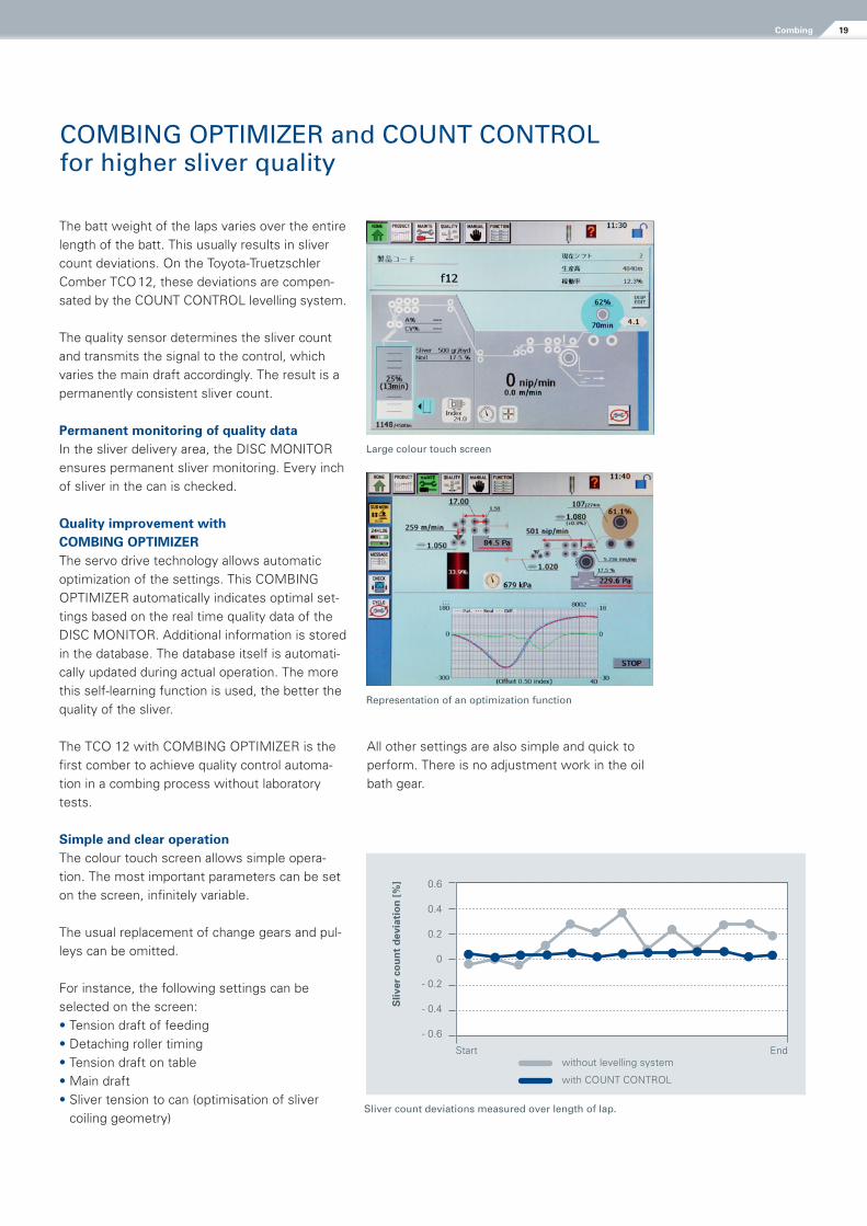
The batt weight of the laps varies over the entire length of the batt. This usually results in sliver count deviations. On the Toyota-Truetzschler Comber TCO 12, these deviations are compen-sated by the COUNT CONTROL levelling system.
The quality sensor determines the sliver count and transmits the signal to the control, which varies the main draft accordingly. The result is a permanently consistent sliver count.
Permanent monitoring of quality dataIn the sliver delivery area, the DISC MONITOR ensures permanent sliver monitoring. Every inch of sliver in the can is checked.
Quality improvement with COMBiNG OPTiMiZErThe servo drive technology allows automatic optimization of the settings. This COMBING OPTIMIZER automatically indicates optimal set-tings based on the real time quality data of the DISC MONITOR. Additional information is stored in the database. The database itself is automati-cally updated during actual operation. The more this self-learning function is used, the better the quality of the sliver.
The TCO 12 with COMBING OPTIMIZER is the first comber to achieve quality control automa-tion in a combing process without laboratory tests.
Simple and clear operationThe colour touch screen allows simple opera-tion. The most important parameters can be set on the screen, infinitely variable.
The usual replacement of change gears and pul-leys can be omitted.
For instance, the following settings can be selected on the screen:• Tension draft of feeding• Detaching roller timing • Tension draft on table• Main draft• Sliver tension to can (optimisation of sliver
coiling geometry)
All other settings are also simple and quick to perform. There is no adjustment work in the oil bath gear.
Sliver count deviations measured over length of lap.
Large colour touch screen
Representation of an optimization function
0.6
0.4
0.2
0
- 0.2
- 0.4
- 0.6
Start End
Sliv
er c
ou
nt
dev
iati
on
[%
]
without levelling system
with COUNT CONTROL
19Combing
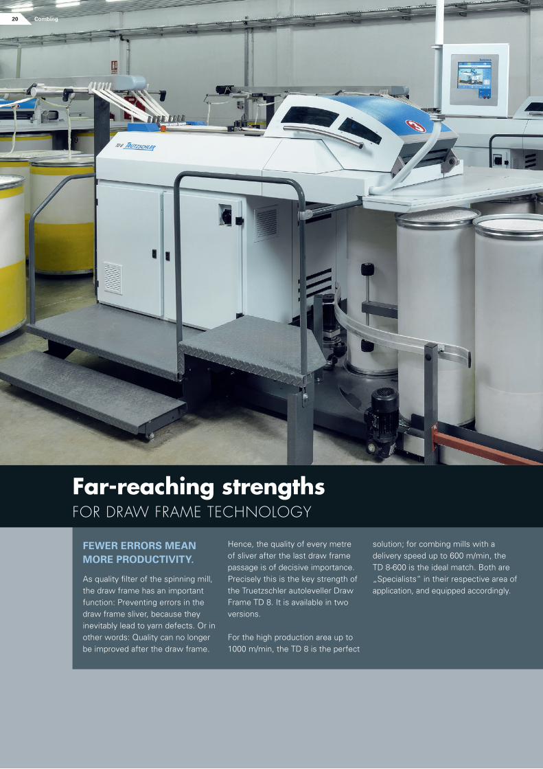
FEwEr ErrOrS MEAN MOrE PrODUCTiviTy.
As quality filter of the spinning mill, the draw frame has an important function: Preventing errors in the draw frame sliver, because they inevitably lead to yarn defects. Or in other words: Quality can no longer be improved after the draw frame.
solution; for combing mills with a delivery speed up to 600 m/min, the TD 8-600 is the ideal match. Both are „Specialists“ in their respective area of application, and equipped accordingly.
Hence, the quality of every metre of sliver after the last draw frame passage is of decisive importance. Precisely this is the key strength of the Truetzschler autoleveller Draw Frame TD 8. It is available in two versions.
For the high production area up to 1000 m/min, the TD 8 is the perfect
Far-reaching strengths for DrAw frAMe technology
20 Combing
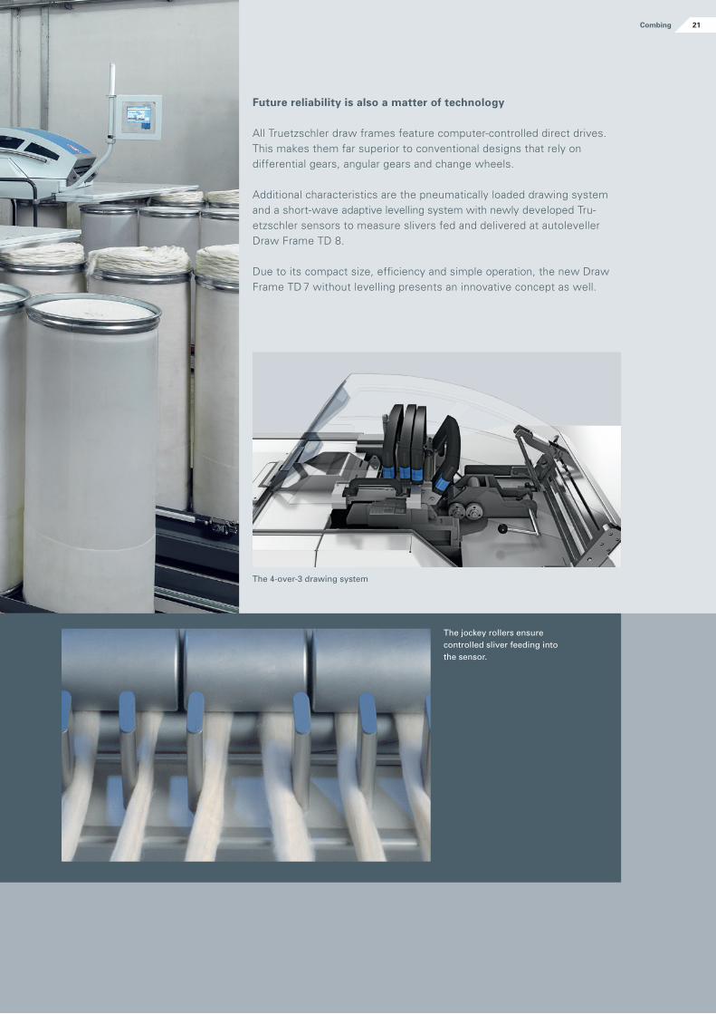
The jockey rollers ensure controlled sliver feeding into the sensor.
Future reliability is also a matter of technology
All Truetzschler draw frames feature computer-controlled direct drives. This makes them far superior to conventional designs that rely on differential gears, angular gears and change wheels.
Additional characteristics are the pneumatically loaded drawing system and a short-wave adaptive levelling system with newly developed Tru-etzschler sensors to measure slivers fed and delivered at autoleveller Draw Frame TD 8.
Due to its compact size, efficiency and simple operation, the new Draw Frame TD 7 without levelling presents an innovative concept as well.
The 4-over-3 drawing system
21Combing
With the Truetzschler autoleveller Draw Frame TD 8-600 this is not necessary. Its self-optimis-ing function OPTI SET is a standard feature that automatically determines the optimum value by considering such parameters as machine settings, material characteristics and ambient atmosphere.
SErvO DrAFT: The key to extremely short correction lengths SERVO DRAFT provides highly dynamic com-pensation of deviations from the target sliver weight. To achieve this degree of short-term levelling, which cannot be realised with conven-tional concepts, SERVO DRAFT uses special drives, determines precise actual values, ensures fault-free signal processing and direct conver-sion of the levelling signal.
The new groove and sensing roll unit DiSC LEvELLErThe sensor is based on friction-free, fiber-friend-ly measurement. It allows a very high, adjust-able pressure at the measuring point, thus the deviations in material thickness must be placed on the same level as the actual mass devia-tions. The sensor features maximum accuracy and signal quality, without interference from external sources. Translating these signals into draft changes with SERVO DRAFT results in a perfectly levelled sliver and consistent sliver count stability.
DISC LEVELLER is equipped with a new, perma-nently lubricated bearing that features a more rigid design than conventional constructions; nevertheless, it allows quick and simple replace-ment of the groove and sensing rolls during lot change.
The Truetzschler Finisher Draw Frame TD 8-600 is a special draw frame for combing.Limiting delivery speeds to 600 m/min reduces energy consumption. The levelling behaviour is precisely optimized to the standard combing speeds of 450 - 550 m/min.
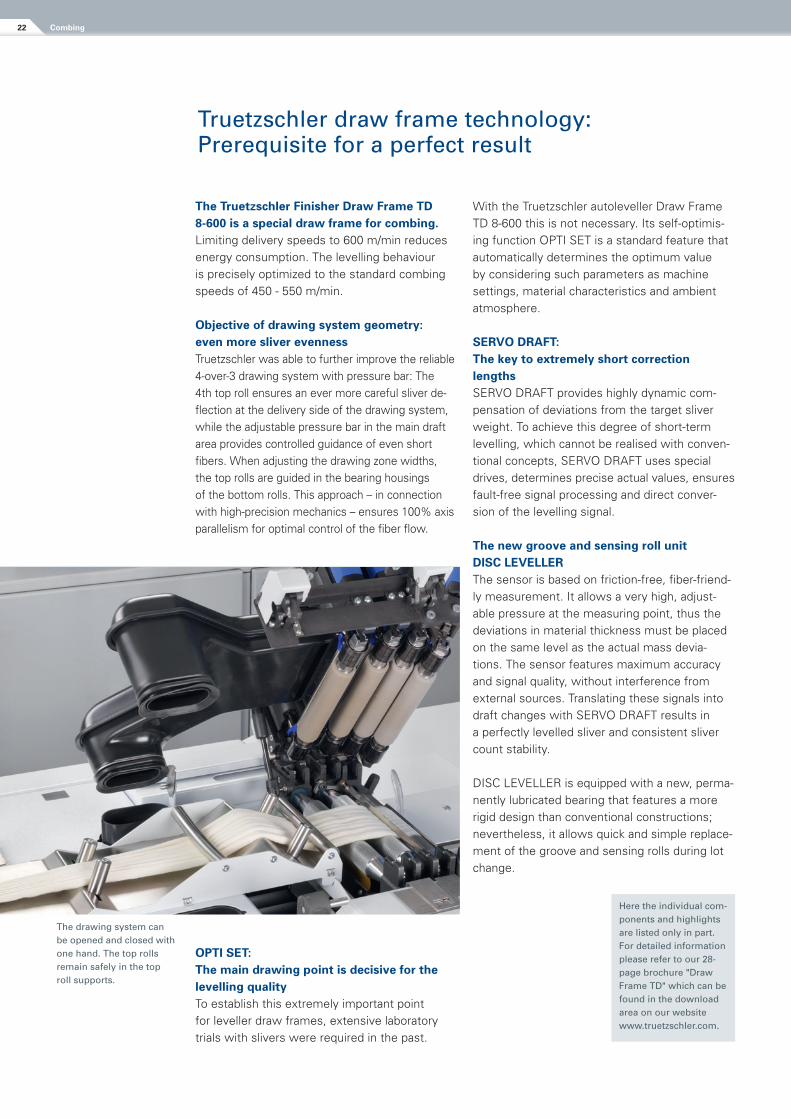
Objective of drawing system geometry: even more sliver evenness Truetzschler was able to further improve the reliable 4-over-3 drawing system with pressure bar: The 4th top roll ensures an ever more careful sliver de-flection at the delivery side of the drawing system, while the adjustable pressure bar in the main draft area provides controlled guidance of even short fibers. When adjusting the drawing zone widths, the top rolls are guided in the bearing housings of the bottom rolls. This approach – in connection with high-precision mechanics – ensures 100% axis parallelism for optimal control of the fiber flow.
The drawing system can be opened and closed with one hand. The top rolls remain safely in the top roll supports.
OPTi SET: The main drawing point is decisive for the levelling qualityTo establish this extremely important point for leveller draw frames, extensive laboratory trials with slivers were required in the past.
Here the individual com-ponents and highlights are listed only in part. For detailed information please refer to our 28-page brochure "Draw Frame TD" which can be found in the download area on our website www.truetzschler.com.
Truetzschler draw frame technology: Prerequisite for a perfect result
Combing22
The SERVO CREEL with its separate drive
The display of the autoleveller draw frame is swivel-mounted and located in the direct working area of the operator.
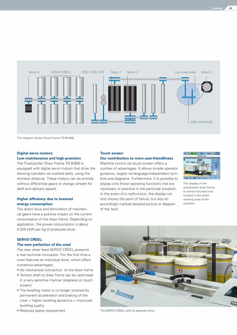
The diagram shows Draw Frame TD 08-600.
Digital servo motors: Low-maintenance and high-precision The Truetzschler Draw Frame TD 8-600 is equipped with digital servo motors that drive the drawing cylinders via toothed belts, using the shortest distance. These motors can do entirely without differential gears or change wheels for draft and delivery speed.
Higher efficiency due to lowered energy consumption The direct drive and elimination of mechani-cal gears have a positive impact on the current consumption of the draw frame: Depending on application, the power consumption is about 0.020 kWh per kg of produced sliver.
SErvO CrEEL: The new perfection of the creel The new sliver feed SERVO CREEL presents a real technical innovation. For the first time a creel features an individual drive, which offers numerous advantages:• No mechanical connection to the draw frame• Tension draft to draw frame can be optimised
in a very sensitive manner (stepless on touch screen)
• The levelling motor is no longer strained by permanent acceleration and braking of the creel = higher levelling dynamics = improved levelling quality
• Reduced space requirement
SERVO CREELMotor 4 DISC LEVELLER Motor 1 Motor 2 Can coiler plate
DISC MONITOR
Motor 3
Touch screen: Our contribution to more user-friendliness Machine control via touch screen offers a number of advantages: It allows simple operator guidance, largely via language-independent sym-bols and diagrams. Furthermore, it is possible to display only those operating functions that are necessary or practical in the particular situation. In the event of a malfunction, the display not only shows the point of failure, but also an accordingly marked detailed picture or diagram of the fault.
23Combing
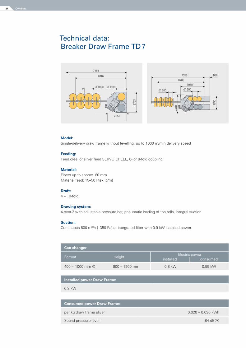
Model:Single-delivery draw frame without levelling, up to 1000 m/min delivery speed
Feeding:Feed creel or sliver feed SERVO CREEL, 6- or 8-fold doubling
Material:Fibers up to approx. 60 mm Material feed: 15–50 ktex (g/m)
Draft:4 – 10-fold
Drawing system:4-over-3 with adjustable pressure bar, pneumatic loading of top rolls, integral suction
Suction:Continuous 600 m3/h (–350 Pa) or integrated filter with 0.9 kW installed power
Can changer
Format HeightElectric power
installed consumed
400 – 1000 mm 900 – 1500 mm 0.8 kW 0.55 kW
installed power Draw Frame:
6.3 kW
Consumed power Draw Frame:
per kg draw frame sliver 0.020 – 0.030 kWh
Sound pressure level: 84 dB(A)
Technical data: Breaker Draw Frame TD 7
8364 8399
4614
8084
7434
8154
7504
47544684
9414 688
688 688
*
1650
1850
* *
1450
4649
6889449
* 1550
7451
6407
2651
2763
7358
6708
3958
688
1850
2448
8364 8399
4614
8084
7434
8154
7504
47544684
9414 688
688 688
*
1650
1850
* *
1450
4649
6889449
* 1550
7451
6407
265127
63
7358
6708
3958
688
1850
2448
Combing24
Production: 400 kg/h
Delivery speed: max. 150 m/min
Working width: 300 mm
Lap diameter: max. 650 mm
Lap tube diameter: 200 mm
Time of lap forming: 3 min
Lap changing time: less than 30 sec.
Lab weight: max. 25 kg
Batt weight: 50 to 80 ktex (300 mm width)
Total draft: 1.14 – 3.33
Can diameter: 600 ... 1000 mm
Can height: up to 1500 mm
Doublings: 24, 28, 32 fold
Total installed power: 13.8 kW
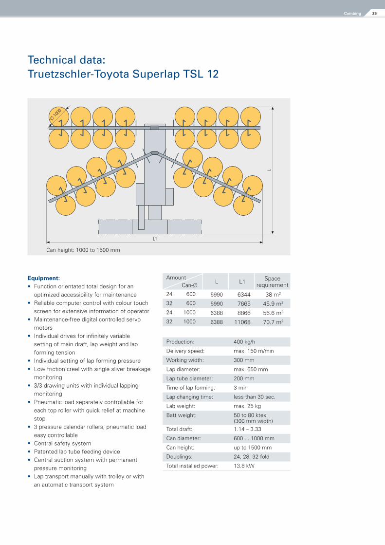
Amount Can-
L L1 Space requirement
24 600 5990 6344 38 m2
32 600 5990 7665 45.9 m2
24 1000 6388 8866 56.6 m2
32 1000 6388 11068 70.7 m2
Equipment:• Function orientated total design for an
optimized accessibility for maintenance• Reliable computer control with colour touch
screen for extensive information of operator• Maintenance-free digital controlled servo
motors• Individual drives for infinitely variable
setting of main draft, lap weight and lap forming tension
• Individual setting of lap forming pressure• Low friction creel with single sliver breakage
monitoring• 3/3 drawing units with individual lapping
monitoring• Pneumatic load separately controllable for
each top roller with quick relief at machine stop
• 3 pressure calendar rollers, pneumatic load easy controllable
• Central safety system• Patented lap tube feeding device • Central suction system with permanent
pressure monitoring• Lap transport manually with trolley or with
an automatic transport system
Technical data:Truetzschler-Toyota Superlap TSL 12
L
L1
� 10
00
Can height: 1000 to 1500 mm
25Combing
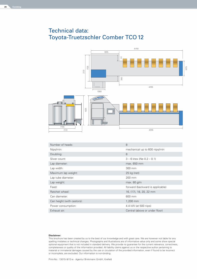
Technical data: Toyota-Truetzschler Comber TCO 12
Number of heads: 8
Nips/min: mechanical up to 600 nips/min
Doubling: 8
Sliver count: 3 – 6 ktex (Ne 0.2 – 0.1)
Lap diameter: max. 650 mm
Lap width: 300 mm
Maximum lap weight: 25 kg (net)
Lap tube diameter: 200 mm
Lap weight: max. 80 g/m
Feed: forward (backward is applicable)
Ratchet wheel: 16, (17), 18, 20, 22 mm
Can diameter: 600 mm
Can height (with castors): 1,200 mm
Power consumption: 4.4 kW (at 500 nips)
Exhaust air: Central (above or under floor)
Disclaimer:This brochure has been created by us to the best of our knowledge and with great care. We are however not liable for any spelling mistakes or technical changes. Photographs and illustrations are of informative value only and some show special optional equipment that is not included in standard delivery. We provide no guarantee for the current relevance, correctness, completeness or quality of the information provided. All liability claims against us or the respective author pertaining to material or immaterial damages caused by the use or circulation of the provided information, even if found to be incorrect or incomplete, are excluded. Our information is non-binding.
Print-No.: 13015-9/13-e · Agentur Brinkmann GmbH, Krefeld
1705
2131
1855
1080
4295
4295
6150
1925
2131
1705
300
1075
331
Combing26
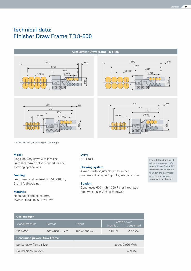
Model:Single-delivery draw with levelling, up to 600 m/min delivery speed for post combing applications
Feeding:Feed creel or sliver feed SERVO CREEL, 6- or 8-fold doubling
Material:Fibers up to approx. 60 mm Material feed: 15–50 ktex (g/m)
Draft:4 –11-fold
Drawing system:4-over-3 with adjustable pressure bar, pneumatic loading of top rolls, integral suction
Suction:Continuous 600 m3/h (–350 Pa) or integrated filter with 0.9 kW installed power
Technical data: Finisher Draw Frame TD 8-600
Can changer
Model/machine Format HeightElectric power
installed consumed
TD 8-600 400 – 600 mm 900 – 1500 mm 0.8 kW 0.55 kW
Consumed power Draw Frame:
per kg draw frame sliver about 0.020 kWh
Sound pressure level: 84 dB(A)
Autoleveller Draw Frame TD 8-600
* 2070-3510 mm, depending on can height
8364 8399
4614
8084
7434
8154
7504
47544684
9414 688
688 688
*
1650
1850
* *
1450
4649
6889449
* 1550
7451
6407
2651
2763
7358
6708
3958
68818
50
2448
8364 8399
4614
8084
7434
8154
7504
47544684
9414 688
688 688
*
1650
1850
* *
1450
4649
6889449
* 1550
7451
6407
2651
2763
7358
6708
3958
688
1850
2448
For a detailed listing of all options please refer to our "Draw Frame TD" brochure which can be found in the download area on our website www.truetzschler.com.
27Combing
www.truetzschler.com
N O N W O V E N SS P I N N I N G MAN-MADE F IBERS C A R D C L O T H I N G
Opening/Blending
Card feeding
Cards/Crosslapping
Wet laying lines
Web needling
Hydro entanglement
Chemical bonding
Thermobonding
Finishing
Drying
Heatsetting
Winding
Slitting
Fiber preparation
- Bale opening
- Blending
- Cleaning
- Opening
- Foreign matter
separation
- Dedusting
- Tuft blending
- Waste recycling
Cards
Draw frames
Combing machinery
Staple fiber lines
Filament lines
- BCF
- Industrial yarn
Precursor lines
Carbon fiber lines
Metallic wires
- Spinning
- Nonwovens/
Longstaple
- Open End
Flat tops
Fillets
Carding segments
Service machines
Service 24/7