TRL Limited PUBLISHED PROJECT REPORT PPR080 TYRE BALES …
115
TRL Limited PUBLISHED PROJECT REPORT PPR080 TYRE BALES IN CONSTRUCTION Version: 1.0 by M G Winter, G R A Watts and P E Johnson (TRL Limited) Prepared for: Project Record: The Research Foundation 062: Tyre Bales in Construction Client: The Research Foundation (J Lewis) Copyright TRL Limited 2006 This report has been prepared for The Research Foundation. The views expressed are those of the author(s) and not necessarily those of The Research Foundation. Published Project Reports are written primarily for the Customer rather than for a general audience and are published with the Customer’s approval. Approvals Project Manager Quality Reviewed
Transcript of TRL Limited PUBLISHED PROJECT REPORT PPR080 TYRE BALES …

TRL Limited
PUBLISHED PROJECT REPORT PPR080
TYRE BALES IN CONSTRUCTION Version: 1.0
by M G Winter, G R A Watts and P E Johnson (TRL Limited)
Prepared for: Project Record: The Research Foundation 062: Tyre Bales in Construction
Client: The Research Foundation (J Lewis)
Copyright TRL Limited 2006 This report has been prepared for The Research Foundation. The views expressed are those of the author(s) and not necessarily those of The Research Foundation. Published Project Reports are written primarily for the Customer rather than for a general audience and are published with the Customer’s approval.
Approvals
Project Manager
Quality Reviewed

This report has been produced by TRL Limited, under/as part of a Contract placed by The Research Foundation. Any views expressed are not necessarily those of The Research Foundation. TRL is committed to optimising energy efficiency, reducing waste and promoting recycling and re-use. In support of these environmental goals, this report has been printed on recycled paper, comprising 100% post-consumer waste, manufactured using a TCF (totally chlorine free) process.

TRL Limited PPR 080
PROJECT ADVISORY GROUP
The authors are sincerely grateful to the contributions of the project advisory group. The members of the group are as follows:
1. Diego Belalcazar, Onyx Environmental Trust.
2. Ed and Nancy Drews, Encore Systems Inc., Cohasset, MN, USA (C).
3. Stephen Kerr, Avayl Engineering Consulting.
4. Forbes Macgregor, Scottish Executive.
5. Richard Myers, Inverness and Nairn Enterprise.
6. Professor Andrew Porteous, Onyx Environmental Trust.
7. Malcolm Ross, NTR Ltd.
8. Dennis Scott, NTR Ltd.
9. Garry Smith, Highland Council.
10. Ken Smith, Department of Public Facilities, Chautauqua County, NY, USA (C).
11. Richard Williammee, Fort Worth District, Texas Department of Transportation, TX, USA (C).
(C = Corresponding Member.)
Funding for this project was provided by Onyx Environmental Trust in the form of a grant placed on The Research Foundation under the Landfill Tax Credits Scheme. Inverness & Nairn Enterprise and the Scottish Executive provided additional funding. The work has been conducted by TRL Limited under contract to The Research Foundation. In addition credit is due to the Royal Academy of Engineering who provided part-funding, in the form of an International Travel Award (No. 04-301), for the first of two study visits to the USA to visit sites at which tyre bales had been used and personnel expert in their use.
The authors are also extremely grateful to Bill Prikryl (TEAM Consultants Inc, Dallas, TX, USA), Dr Jorge Zornberg and Chris LaRocque (University of Texas at Austin, USA), and Jonathan Simm (HR Wallingford, UK) for helpful discussions and suggestions.
The TRL Project Team was led by Dr Mike Winter with inputs from Guy Watts, Paul Johnson, Dr Murray Reid, Polly Griffiths and Dr Devin Sapsford.

TRL Limited PPR 080
UNITS AND TERMS The concept of baling tyres to produce a construction material was conceived in the United States of America. As a result many of the basic dimensions of, for example, the bales are in non-SI units. In addition, many of the best examples of the use of tyre bales are from the USA. Where appropriate the authors have maintained the use of non-SI units and placed the SI units in parentheses immediately after: thus 40 feet is denoted as 40' (12.19m) and similarly 12 inches is denoted by 12'' (0.305m).
It is to be hoped that by adopting this approach the work presented here will not only be of immediate use in the UK and Europe, but also be of benefit to the tyre baling industry in the USA.
A list of relevant conversion factors taken from Glover (1997) and Lambe and Whitman (1979) is given below:
To convert from To Multiply by
Inches m 0.0254
Feet m 0.3048
Yards m 0.9144
Square inches m2 0.645 × 10⁻⁵
Square feet m2 0.0929
Square yards m2 0.8361
Cubic feet m3 0.02832
Cubic inches m3 1.639 × 10⁻⁵
Cubic yards m3 0.76455
Pounds kg 0.4536
Tons Tonnes 0.90718
Tons force kN 8.89645
Pounds per square inch kN/m2 (kPa) 6.895
Pounds per square foot kN/m2 (kPa) 0.04788
Pounds per cubic inch kg/m3 27679.9
Pounds per cubic inch kN/m3 271.54
Pounds per cubic foot kg/m3 16.0185
Pounds per cubic foot kN/m3 0.157

TRL Limited PPR 080
CONTENTS
Executive Summary i
1 Introduction 1
2 Background 3
2.1 The Need for Tyre Baling 3 2.2 Energy Use 6 2.3 Properties 6 2.4 Increasing the Use of Tyre Bales 7 2.5 The Project 7 2.6 Sustainability 8 2.7 Waste Management Licensing 9
3 Potential Applications 10
3.1 Brief Descriptions of Potential Applications 10 3.2 Selection of Applications for Further Study 16
4 Properties and Behaviour 17
4.1 Dimensions and Volume 17 4.2 Mass and Density 17 4.3 Frictional Response 18 4.4 Stress-Strain Response 20 4.5 Creep 20 4.6 Permeability 21 4.7 Porosity 21 4.8 Durability 22 4.9 Contamination Potential 23 4.10 Fire Resistance 24 4.11 Human Health and Safety 26
5 Application Guides 28
5.1 Road Foundations Over Soft Ground 28 5.2 Slope Failure Remediation 36 5.3 Lightweight Embankment Fill 43 5.4 Gravity Retaining Walls 47 5.5 Drainage Layers (or Drainage Paths) 52 5.6 Storm Water Management Systems and Rainwater Soakaways 56 5.7 Environmental Barriers 64
6 Construction Issues 68
6.1 Supply and Production of Tyre Bales 68 6.2 Handling of Tyre Bales 69 6.3 Alignment and Layout 70 6.4 Fill Around Bales 72 6.5 Maximum Height of Tyre Bale Fill 73 6.6 Cover Depth and Stability of Cover 73

TRL Limited PPR 080
6.7 Drainage 75 6.8 Contamination 76 6.9 Costs 76 6.10 End of Service Life 77
7 Summary and Recommendations 78
Acknowledgements 80
References 80
Appendix A. Waste Management Licensing of Tyre Bales 85
A.1 Definition of waste 85 A.2 Case law and its implications 86 A.3 Exemptions to the Regulations 92 A.4 Other Legislative Issues 93 A.5 Waste Management Regulations Amendments 93
Appendix B. Manufacture of Tyre Bales 94
B.1 The Tyre Baler 94 B.2 Composition of the Standard Tyre Bale 94 B.3 Assembling the Bale 94 B.4 Long-Term Stability of Tyre Bales 99 B.5 Non-Standard Tyre Bales 103
Appendix C. Specification for Tyre Bales 106

TRL Limited i PPR 080
Unpublished Project Report Version: 1.0
Executive Summary Around 38.7M tyres (or 440,000t) were scrapped in the UK in 1998. In Scotland more recent and accurate data is available corresponding to 2.8M tyres (or 32,000t) in 1999. In the recent past by far the bulk of these have been sent for energy recovery, stockpiled, disposed of in landfill or disposed of illegally. However, the EC Landfill Directive outlawed the disposal of whole tyres in landfill from June 2003 and will outlaw the disposal of shredded tyres to landfill by 2006. In addition there is no provision in the Directive to allow the use of tyre shred for engineering purposes in landfill.
Clearly alternative means of disposal are required. It is expected that a significant proportion of the UK's used tyre production and existing stock will be consumed by energy recovery and waste-to-energy plant (including pyrolysis and burning in cement kilns). However, such activities will not account for all used tyres and a significant proportion is expected to remain available for alternative uses, not least as many such activities are subject to the vagaries of a changing market.
Other forms of potential recovery for waste tyres include retreading, material recovery (mainly crumbing) for use in new rubber products, and use in civil engineering. Civil engineering applications take on many forms ranging from landfill engineering through lightweight fill, soil reinforcement, drainage, erosion control, artificial reefs, hydrocarbon retardation in ground barriers and noise barriers, to thermal insulation.
The form in which the tyre material may be used varies from small crumb and shred particles up to whole tyres, depending upon the application and the technical requirements thereof. The fabrication of tyre bales is a relatively new means of tyre recovery.
Waste Management Licensing has been a concern for some time as various Regulators have taken differing views as to whether tyres (and tyre bales) either constituted, or should be treated as, a waste. However, as of late-2005 both UK-mainland Regulators have taken the view that tyre baling and the subsequent use of such materials in construction is a low risk activity and that Waste Management Licenses will not be required for such activities.
This report deals throughout with the URRO (Used Rubber Recycling Operation) Block, a form of tyre bale specifically designed for use in engineering works (as opposed to facilitating storage or transport of tyres for example). The report refers to URRO blocks as tyre bales throughout.
Approximately 110 to 120 tyres are compressed in a bespoke baling machine and restrained with tie-wires. The process produces a rectilinear bale of approximate dimensions 1.30m by 1.53m by 0.82m, mass of around 890kg and a density of approximately 0.55Mg/m3. In addition to being considerably less dense than most conventional construction products, and therefore being highly suitable for construction over soft ground, the bales are highly permeable. These two features indicate that tyre bales are likely to play an increasing part in the future of construction works. In addition the baling process is a low energy option compared to other tyre recovery processes. During the tenure of this project tyre bales have been used in applications ranging from road foundations over soft ground, through slope failure remediation to soakaway construction amongst other diverse applications.
One of the main purposes of the project was to assist the tyre baling industry in achieving increases to the volume of tyre bales used in construction and, at the same time, to help raise the utility (or value) of those applications. This was to be achieved by preparing guidance on the design, construction and specification of tyre bales in construction. There are strong signs that this and other projects conducted in both the UK and the USA have contributed strongly to the emerging market for tyre bales for use in construction.
This report presents a series of guides which detail possible approaches to the design and construction of a wide range of applications: road foundations over soft ground; slope failure remediation; lightweight embankment fill; gravity retaining walls; drainage layers; storm water management systems and rainwater soakaways; and environmental barriers. These applications were selected from more than 20 potential applications for tyre bales in construction in close consultation with the Project Advisory Group.

TRL Limited ii PPR 080
Unpublished Project Report Version: 1.0
The application guides are supported by an extensive study of key properties and behaviours including dimensions, volume, mass, density, mechanical properties, hydraulic properties and behaviours in relation to durability, contamination potential, fire resistance, and human health and safety. Issues common to multiple applications are also presented, including the supply and construction of bales, their handling, alignment and layout, fill around the bales, maximum height of tyre bale fill, cover depth and cover stability, drainage, contamination, typical costs, and end of service life.
The manufacturing process of tyre bales is described in some detail and, with other information, used as the basis for an engineering specification.
Current needs for further research are clear. High quality mechanical tests should be a priority and include frictional response, stiffness and creep. Tests to date have been either fit-for-purpose or conducted on bales in the USA. The fit-for-purpose tests have generally been designed to suit a construction project-specific purpose and may be more or less transferable to more general uses. Tyres in the USA are generally larger than those used in Europe. Consequently tyre bales contain up to 17% fewer tyres. This will have an impact upon the internal structure of the bales and upon the properties; the significance of this impact upon the measured properties of tyre bales is a relative unknown at present.
Pilot-scale or full-scale tests are also considered to be a priority. These may take the form of structures that are specifically constructed to be monitored in a controlled environment over the long-term or they may be intended for test to failure.
The production of a formal, non-product specific, specification which can be accepted by all quarters of the construction industry should also be a priority. This will need to be supported by detailed technical information.
Certainly the monitoring of tyre bale structures for deformation, leachate, temperature in the long-term and UV degradation over time would be a welcome opportunity to gather data of great value in confirming behaviours implied largely from desk study information.
The lack of data from such exercises should not preclude the further use of tyre bales in construction, nor should it prevent the development of tyre bale applications. However, the availability of data from such exercises should encourage and accelerate the take up of tyre bales and the development of the applications and market for tyre bales.

1TRL Limited 1 PPR 080
Published Project Report Version: 1.0
1 Introduction Around 38.7M tyres (or 440,000t) were scrapped in the UK in 1998 (Hird et al., 2001). In Scotland more recent and accurate data is available corresponding to 2.8M tyres (or 32,000t) in 1999 (SEPA, 2002). In the recent past by far the bulk of these have been sent for energy recovery, stockpiled, disposed of in landfill or disposed of illegally (Hird et al., 2001). However, the EC Landfill Directive outlawed the disposal of whole tyres in landfill from June 2003 and will outlaw the disposal of shredded tyres to landfill by 2006. A useful review of the status of post-consumer tyres in the EU is provided by Shulman (2002).
Clearly alternative means of disposal are required. It is expected that a significant proportion of the UK's used tyre production and existing stock will be consumed by energy recovery and waste-to-energy plant (including pyrolysis and burning in cement kilns) for example. However, such activities will not account for all used tyres and a significant proportion is expected to remain available for alternative uses.
Other forms of potential recovery for waste tyres include retreading, material recovery (mainly crumbing) for use in new rubber products and use in civil engineering. Civil engineering applications take on many forms ranging from landfill engineering through lightweight fill, soil reinforcement, drainage, erosion control, artificial reefs, hydrocarbon retardation in ground barriers and noise barriers, to thermal insulation (Hylands and Shulman, 2003).
The form in which the tyre material may be used varies from small crumb and shred particles up to whole tyres, depending upon the application and the technical requirements thereof. The fabrication of tyre bales, although mentioned by Hylands and Shulman (2003), is a relatively new means of tyre recovery.
This report deals throughout with the URRO (Used Rubber Recycling Operation) Block, a form of tyre bale specifically designed for use in engineering works (as opposed to facilitating storage or transport of tyres for example). The report refers to URRO blocks as tyre bales throughout.
Tyre baling involves the use of a specialist machine to produce a highly compressed, lightweight block containing in excess of 110 to 120 tyres for use in construction. The dimensions of the block are approximately 1.30m by 1.53m by 0.82m and the blocks have a density of around 0.55Mg/m3, representing a volume reduction compared to the loose tyres of around four or five to one. The blocks are usually tied by galvanised steel wires (mesh and polymeric materials can also be used depending upon the installation environment) and when completed are sufficiently regular that they may be stacked. Importantly the baling machine is trailer mounted and may be relatively easily transported to locations where there are large volumes of tyres.
Section 2 of this report contains relevant background information on the need for tyre baling, comparative energy use for tyre baling and other means of recycling tyres, and a note of the key properties of tyre bales. It also examines the type of construction projects that are currently utilising tyre bales and explains how the project for which this document forms the final report aims to increase the utility, or value, of future tyre bale applications. The potential impact of the use of tyre bales in construction on the UK Government’s four pillars of sustainability is examined and the Waste Management Licensing regime in relation to tyre bales summarised. A brief overview of the project objectives is also given.
Section 3 considers more than 20 potential applications of tyre bales in construction, giving a brief overview of each. Key applications are identified to be taken forward for further work in Section 5.
Section 4 details the relevant properties and behaviours of tyre bales. These are selected in response to the key applications identified in Section 3 for further study in Section 5. The key relevant properties and behaviours include:
• Dimensions.
• Volume.
• Mass.

2TRL Limited 2 PPR 080
Published Project Report Version: 1.0
• Density.
• Mechanical properties.
• Hydraulic properties.
• Durability.
• Contamination potential
• Fire resistance.
• Human health and safety.
Section 5 gives a series of guides for the design and construction of key tyre bale applications selected from the overview presented in Section 3. The applications studied are:
• Road foundations over soft ground.
• Slope failure remediation.
• Lightweight embankment fill.
• Gravity retaining walls.
• Drainage layers.
• Storm water management systems and rainwater soakaways.
• Environmental barriers.
Section 6 gives additional information on construction issues that are common to a number of the applications described in Section 5. These issues include the supply and manufacture of bales, their handling, alignment and layout, fill around the bales, maximum height of tyre bale fill, cover depth and cover stability, drainage, contamination, typical costs, and end of service life.
Section 7 summarises the work and draws conclusions and makes recommendations for further work.
Appendix A presents an extensive review of the key issues in relation to the Waste Management Licensing of tyre bales including its development over time, while Appendices B and C consider the manufacture and specification of tyre bales.

3TRL Limited 3 PPR 080
Published Project Report Version: 1.0
2 Background
2.1 The Need for Tyre Baling
The generation of scrap tyres is by no means a problem unique to the United Kingdom. In the USA it has been estimated that more than 2 billion used tyres are stockpiled, and an additional 285M added each year. In the state of Texas alone 69M scrap tyres are estimated to be stockpiled and a further 24M added each year.
The disposal of tyres can be problematic. Sonti et al. (2000) note that not only are tyre mounds an eyesore, but that they can also provide a breeding ground for mosquitoes. Indeed, used tyre stockpiles have been linked with outbreaks of West Nile Fever in the USA (Anon, 1998; 2001). In addition to any legal constraints, whole tyres cannot usually be placed in bulk landfill because they may trap gases and float to the top, potentially punching holes in daily and final landfill cover. However, the over-riding constraint is that care must be taken when stockpiling tyres for the fear of exothermic oxidation reactions creating conditions that favour the combustion of whole tyre stockpiles by the unwary and the arsonist.
Due to the air pockets that are within tyres and tyre dumps it is extremely difficult to put out tyre fires and some have burned for months. Air pollutants from tyre fires include toxic gases such as poly-aromatic hydrocarbons (PAHs), carbon monoxide, sulphur dioxide, nitrogen dioxide and hydrochloric acid. In addition oils related to the gaseous compounds indicated above may also leach into groundwater resulting in severe pollution, potentially including to drinking water aquifers.
There have been a number of fires at tyre dumps in the USA. Anecdotal evidence indicates possible causation factors ranging from sparks on dry grass from agricultural equipment and lightning through to arson (see also Section 4.10). One such fire had the effect of precipitating perhaps the most concerted use of tyre bales to date.
In April 1995 Chautauqua County in New York State faced environmental disaster as a fire in a scrap tyre dump at the town of Charlotte burnt on a rural hillside overlooking State Route 60. The fire burned for weeks, costing the local economy hundreds of thousands of US dollars and bankrupted several local fire departments (Anon, 1998; 2001; Winter, 2005). The fire destroyed an estimated 20% to 25% of the 5M tyres stored at the dump (Figures 2.1 to 2.3).
Figure 2.1 – Tyre fire at Hornburg dump, Charlotte, New York State. (Photograph © Chautauqua County Department of Public Facilities.)

4TRL Limited 4 PPR 080
Published Project Report Version: 1.0
Figure 2.2 – Tyre fire at Hornburg dump, Charlotte , New York State. (Photograph © Chautauqua County Department of Public Facilities.)
Figure 2.3 – Tyre fire at Hornburg dump, Charlotte, New York State. (Photograph © Chautauqua County Department of Public Facilities.)
With an estimated 10M scrap tyres stored in the County a solution was needed. In 1998 the County authorities implemented a plan to minimise the number of scrap tyres stored in Chautauqua and thus minimise the potential for another disaster of this nature. Working with the State Department for Transportation and the State Department of Environmental Conservation a research, development and demonstration project was set up to find safe and economical means of dealing with scrap tyres.
Many alternatives were investigated, but due to the low start up costs a tyre baling system was purchased from Encore Systems. The baler was capable of applying up to 65 tons of load to a rectangular bale consisting of 100 tyres (US tyres are generally slightly larger than their UK

5TRL Limited 5 PPR 080
Published Project Report Version: 1.0
counterparts and so more tyres would be expected to comprise a UK built bale) nominally measuring 30'' (0.76m) by 50'' (1.27m) by 60'' (1.52m). The bales were held together by 9 gauge galvanised steel wires and the completed bale represented a 5:1 volume reduction compared to the loosely stored tyres. A particular attraction of the system was that the bales do not hold water and therefore pose no threat to public health due to mosquitoes which carry the West Nile Virus, which has caused several deaths in New York State. The decreased surface area and lack of air/oxygen also meant that the fire hazard was greatly reduced.
The next step was to clean up the second largest tyre dump in the County located at Levant in the town of Poland, containing 150,000 to 250,000 tyres. The dump was located less than 1000' (300m) from a large school and church complex, less than 500' (150m) from the Interstate I86, Southern Tier Expressway and the primary east-west corridor through the southern part of New York State, and less than 200' (60m) from State Route 394. More importantly the site lay directly over the Cassadaga valley aquifer which supplies drinking water to the counties largest city. A fire at this location would be impossible to contain and the environmental and health impacts potentially extensive.
A county-wide effort to bale the tyres and clean up the site was a success. A former environmental hazard and eyesore was transformed into a viable piece of property ready for use and it was sold within a year.
The tyre bales resulting from the Levant tyre dump were used in a number of demonstration projects. These involved the reconstruction of a number of roads, largely on soft ground where the use of the lightweight tyre bales as a replacement subgrade could confer major engineering benefits (Winter et al., 2005a; 2005b).
Figure 2.4 – Tyre dump at Levant, Poland, New York State. The school and church complex can be seen in the upper part of the picture just below the I86 road. (Photograph © Chautauqua
County Department of Public Facilities.)
Due to the high cost of scrap tyre disposal (around US$2 per tyre) most of the County’s rural towns and villages had their own stockpiles with many also having the problem of tyres dumped illegally alongside the roadside and stored in residents’ yards.
In an effort to rid the landscape of scrap tyres, which in addition to forming a serious health hazard can be an eyesore, a tyre amnesty program was declared. During the spring and summer of 2000 a total of 145,200 tyres were brought to the County Landfill in Ellery, baled and put into storage. It was

6TRL Limited 6 PPR 080
Published Project Report Version: 1.0
found that two operators could bale between 400 and 600 tyres (between 4 and 6 bales) per hour. The programme has continued annually and the fifth annual tyre amnesty was launched in May 2004.
2.2 Energy Use
The energy consumed in a recovery process has a significant impact on the cost of the process and is thus a key component in determining its viability. Not only does energy relate to expenditure on fuel it also correlates with the emissions produced from the process. In the case of tyre bales the energy required to produce a single bale is very small when compared to similar figures (available from ETRA) for other forms of recovery, as follows:
Tyre bale: 7.5 kWh/t1.
Tyre shred/chip production: 125 kWh/t.
De-vulcanisation: 150-200 kWh/t.
Pyrolysis: 370 kWh/t.
Clearly the energy required to recover used tyres as tyre bales is a small fraction of that required to conduct other recovery processes, in the case of the examples cited above between 2% and 6%. This makes a very strong case for tyre bales as an energy efficient and economical means of recovery for used tyres.
2.3 Properties
The basis properties and behaviours of tyre bales confer a number of advantages on them as a potential construction material when compared to many conventional, primary materials. These properties and characteristics include the following:
1. Low weight.
2. Low lateral earth pressure.
3. Good drainage.
4. Compaction not required.
5. Can be stacked in a variety of interlocking patterns to form a stable mass.
6. Comprise recycled materials.
7. Treated by Environmental Regulator as raw material.
8. Good thermal insulation.
9. Can be used untreated if buried or encapsulated for visible applications.
10. Non-polluting.
11. Low cost.
Although compaction of the bales is not required, the shape of the bales is not entirely rectilinear and thus dictates that spaces will be left between the bales when they are placed in construction. In order to ensure adequate stiffness is achieved in load-carrying applications, fine aggregate is placed into the gaps and this must receive a degree of densification. This is an unusual process and must be planned for in the construction process, albeit that it can be achieved simply without the use of specialist plant.
1 The output power of the engine used by Northern Tyre Recycling Ltd is 40 hp at 2800 rpm (the engine is usually run at around 2,500 rpm). As 1 hp (mechanically derived) is equal to 0.7456 kW (Glover, 1997) then the power output of the engine at 2,800 rpm is 29.8 kW. A bale typically takes around one-quarter of an hour to manufacture thus consuming around 7.5 kWh of energy in its manufacture. Assuming a typical bale to be around one tonne in mass then the energy used in the manufacture of tyre bales is around 7.5 kWh/t.

7TRL Limited 7 PPR 080
Published Project Report Version: 1.0
The bales themselves are low cost, especially if viewed on a volumetric basis (i.e., a one tonne bale may occupy the volume of three tonnes of aggregate and be less costly per tonne). However, as may be seen from the preceding paragraph, construction with tyre bales can involve unfamiliar processes compared to conventional construction. However, it is usually much more rapid as effectively the construction is modular and cost advantages over conventional processes are maintained.
Tyre bales are a very useful addition to the current armoury of construction materials. Not least, it is the only genuinely low cost lightweight construction material, being substantially lighter in weight than pulverised fuel ash and greatly more cost effective (although more dense) than expanded polystyrene.
2.4 Increasing the Use of Tyre Bales
At present tyre bales are being successfully used in mainly informal civil engineering applications (e.g., small erosion protection projects), in landfill construction where innovation is less constrained than in other sectors of the construction industry, and in unpaved roads.
Applications in other sectors of the civil engineering industry require a greater degree of design and specification, and a greater consideration of the design life of the completed construction. Experience strongly suggests that without formal design procedures and specifications, consultants and other designers will not use tyre bales in more critical, higher utility or value applications (Winter and Henderson, 2001) due to concerns over the potential exposure of their professional indemnity insurance.
The concept of utility was developed (Winter, 2002) to demonstrate how the same waste material could be used in a number of different applications with different values, or more specifically levels of utility where this was judged against both economic and environmental factors. Figure 2.5 illustrates these levels of utility and, in addition, shows how increasing energy and expense usually leads to a higher utility end product. In the case of tyre bales, current applications are very much in low utility applications.
2.5 The Project
The main aim of this project is to help in lifting the level of utility of typical tyre bale applications through the low utility category into the intermediate category. This is indeed an ambitious target.
This project is intended to contribute to the increased use of tyre bales in construction. The core of the work involved the development of guides to the design and construction of specific potential tyre bale applications, and of a specification for tyre bales. These are intended to provide designers and contractors with the basic information that they need in order to consider tyre bales when planning a construction project.
The audience for the work will include tyre bale manufacturers, contractors, consultants, local authorities, clients and their advisors, developers, and architects. The information is presented in a form that is intended to be suitable for a wide range of potential users. However, it must be emphasised that the use of appropriately qualified and experienced professionals for design and construction is essential, including those projects involving tyre bales.
The results of the project reported here are intended as a significant first step along the road to higher utility applications for tyre bales.

8TRL Limited 8 PPR 080
Published Project Report Version: 1.0
Figure 2.5 – Illustration of how increased energy and expense during the recovery process usually results in products with a higher value or utility (after Winter, 2002; Macgregor, 2004).
2.6 Sustainability
The use of tyre bales appears to have benefits that reflect positively on all four of the pillars of sustainability, as follows:
• Environment: Avoids landfill and/or fly-tipping of used tyres. The process of tyre baling uses a low emission diesel engine in a low energy process. As the plant is mobile it can be transported to stockpiles of tyres allowing such waste to be dealt with locally, satisfying the proximity principle.
• Resource use: The use of tyre bales is usually as a direct substitute for primary aggregate and no waste, in terms of either aggregate or tyres, is generated from their production. In addition high volumes of tyre arisings (in excess of 100 tyres per bale) are consumed by the process.
• Economic: The tyre baling industry has the potential to generate both employment and consequential wealth, not least as the process is relatively labour intensive compared to aggregate production. It is both a cost-effective use of high volumes of used tyres and also an excellent use of tyre arisings.
• Social: Traditional low density construction materials are expensive and some remote infrastructure may be uneconomic to construct and/or repair. This can have significant negative impacts on issues relating to safety, access to employment and quality of life in remote communities. The low density of the tyre bales combined with their relatively low cost can mean that it may be possible to make economically viable repairs to infrastructure that may otherwise have remained unrepaired or even have been closed.
Ene
rgy
Use
d in
Pro
duct
ion
and
Con
stru
ctio
n
Utility of End Product
Low Utility Applications
Intermediate Utility Applications
High Utility Applications
Current tyre bale
applications
Project Target for
Higher Utility Applications
Ene
rgy
Use
d in
Pro
duct
ion
and
Con
stru
ctio
n
Utility of End Product
Low Utility Applications
Intermediate Utility Applications
High Utility Applications
Current tyre bale
applications
Project Target for
Higher Utility Applications

9TRL Limited 9 PPR 080
Published Project Report Version: 1.0
2.7 Waste Management Licensing
The Waste Management Licensing of tyre bales and their subsequent incorporation into construction works is complex.
It is the authors’ view that the baling of tyres to form blocks for use in construction represents not so much a means of disposal as a means of creating a valuable commodity. In the recent past the baling of tyres has been treated as a recovery operation by the UK Regulators. This meant that once the bales had been completed the waste tyres incorporated into it were viewed as fully recovered and no longer a waste. Waste Management Licensing was not therefore required for subsequent storage and use of such bales.
However, case law has modified this interpretation (see Appendix A.2) by essentially deeming that the recovery operation was not complete until the bales were incorporated into the final construction. Thus the bales were treated as waste and a Waste Management License was required, as there is no Exemption from the Waste Management Licensing Regulations for tyre bales, to store and use such materials in construction.
However, as of December 2005, both UK-mainland Regulators (the Environment Agency and the Scottish Environment Protection Agency) have taken the view that tyre baling and the subsequent use of such materials in construction is a low risk activity and that Waste Management Licenses will not be required for such activities.
Appendix A reviews UK Waste Management Licensing with respect to tyre baling, bale storage and bale use.
10TRL Limited 10 PPR 080
Published Project Report Version: 1.0
3 Potential Applications Potential applications for tyre bale use in construction cover a wide range of endeavour and at this stage are most likely limited only by the imagination and experience of those describing the applications. The following list has been drawn up by the authors in consultation with the Project Advisory Group and while not intended to be exhaustive, it certainly covers a wide range of applications:
1. Road or haul road foundations over soft ground.
2. Lightweight embankment fill.
3. Gabion-type walls (including tied-back walls) – possibly mesh wrapped.
4. Earth pressure reduction zones to retaining walls.
5. Backfill to retaining walls.
6. Slope stabilisation applications (similar to 3 above).
7. Drainage layers and storm water management.
8. River erosion control.
9. Marine erosion control.
10. Landfill cells.
11. Marking-out areas on construction and other sites.
12. Concrete encased bales:
a) Low-height, non/low-load-bearing walls (e.g., delimiting working areas).
b) Pinned blocks to allow connection and limited lateral load-bearing capacity (e.g., material storage bays).
13. Polymer encased blocks (high visibility):
a) Crash barriers at roadworks.
b) High visibility markers (for night-time working as at 11(a) above).
14. Walls for low cost farm buildings/barns (with corrugated roofing).
15. Under-floor insulation in new building construction.
16. Climbing frame / pyramid / slide support in children’s playground.
17. Crash cushion for bridge piers or bridge abutments.
18. Combined geomembrane protection and drainage layer for landfill sites.
19. Separation of different stockpiles of material (e.g., graded demolition waste).
20. Scour protection for river bridges.
21. Combined stress absorbing and drainage layer behind integral bridge abutments.
22. Noise bund/noise fence.
3.1 Brief Descriptions of Potential Applications
The potential applications identified above are discussed further in the following Sections, while the applications and the benefits of the properties and characteristics of tyre bales are related in Table 3.1.

11TRL Limited 11 PPR 080
Published Project Report Version: 1.0
Table 3.1 – Characteristics of and applications for tyre bales.
Characteristic1 ==================
Application2
Low
w
eigh
t/den
sity
Low
late
ral
earth
pre
ssur
e
Goo
d dr
aina
ge
Com
pact
ion
not
requ
ired
Var
iety
of
stac
king
pa
ttern
s
Rec
ycle
d m
ater
ial
Reg
ulat
or tr
eats
as
raw
mat
eria
l
Goo
d th
erm
al
insu
latio
n
Use
unt
reat
ed if
bu
ried
Enca
psul
ate
for
high
vis
ibilit
y
Non
-pol
lutin
g
Low
cos
t3
Road foundationEmbankment fillGabion-type walls - -Reducing earth pressureBackfill to retaining wallsSlope stabilisation -Drainage layersRiver erosion -Marine erosion -Landfill cellsMarker blocks -Pinned blocks -Crash barriersNighttime markersFarm barnsUnder-floor insulationChildren's play equipmentCrash cushion piersGeomembrane protectionStockpile separation -Bridge scour protection -Stress absorbing layer to integral bridge abutmentNoise bundRainwater Soakaway
= Excellent characteristic for application. 1 The characteristics are drawn from Section 1 of the report.= Useful characteristic for application. 2 The applications are drawn from Section 3 of the report.= Neutral characteristic for application.
- = Negative characteristic for application.
3 Low cost refers to the bales as a material. It is recognised that other benefitsmay be conferred by the ease of placement of tyre bales in a construction.

12TRL Limited 12 PPR 080
Published Project Report Version: 1.0
3.1.1 Road or Haul Road Foundations Over Soft Ground
Tyre bales are light in weight and even when internal voids and spaces between blocks are filled with sand to improve stiffness and stability they are still considerably lighter than conventional fill used as road foundations. They are long-lasting, non-polluting and require less compaction than conventional fills. They are very much cheaper than special lightweight materials which could be employed for lightweight foundations (e.g., expanded polystyrene blocks). Historically a very similar effect has been achieved for low-volume roads by the use of laterally place fascines or bundles of faggots.
3.1.2 Lightweight Embankment Fill
Tyre bales are light in weight and even when internal voids and spaces between blocks are in filled with sand to improve stiffness and stability they are still considerably lighter than conventional fill employed in embankments. They are long-lasting, non-polluting and require less compaction than conventional fills. They are very much cheaper than special lightweight materials occasionally used currently in light-weight embankments (e.g., expanded polystyrene blocks).
3.1.3 Gabion-Type Walls (Including Tied-Back Walls) – Possibly Mesh Wrapped
Tyre bales are regular in size and fairly regular in shape – the faces are a little convex and irregular compared with a well-filled gabion. They are very much cheaper than rock-filled gabions even when accounting for the rock material used to face the gabions. They are long-lasting and non-polluting. Where gabion faces are visible the hand-picking and packing of stone to give an attractive front face can be very time-consuming. Visible bales faces are fairly unattractive and are likely to be top soiled (or possibly fronted with an improved face) where necessary. Both gabions and bales can be tied-back to the soil behind them probably using a geotextile to produce a form of reinforced soil construction.
3.1.4 Earth Pressure Reduction Zones to Retaining Walls
The overturning force acting on the back of a retaining wall is very dependant on the properties of the soil being retained. Wet, heavy soil with little shear strength will apply large forces leading to the need for a high-strength wall. By replacing some of the soil immediately behind the wall with lightweight tyre bales, which are largely self-supporting, a lighter wall construction can be employed. Tyre bales are long-lasting, non-polluting and require less compaction than conventional fills. Where the retaining wall is acting as a bridge abutment care is needed to ensure that vertical , in addition to horizontal, stresses do not cause excessive compressions where the bales are immediately under the road surface - construction details would need to be carefully considered.
3.1.5 Backfill to Retaining Walls
Similar to the above, the use of tyre bales behind a retaining wall will tend to be beneficial. A retaining wall will normally have a drainage layer against the back face to minimise hydrostatic forces acting on the wall and the permeable bales will form a good drainage path. The lightweight bales will tend to apply a fairly low overturning force to the wall allowing a comparatively lightweight wall design. They are long-lasting, non-polluting and require less compaction than conventional fills. Again for walls used as bridge abutments the compressibility of the bales under the road surface must be carefully considered in the design detailing to ensure that compression immediately behind the wall does not create a step.

13TRL Limited 13 PPR 080
Published Project Report Version: 1.0
3.1.6 Slope Stabilisation Applications
Bales can be used to repair failed slopes or to strengthen slopes considered at risk of failing. They are long-lasting and non-polluting. Their properties mean they can serve a wide number of purposes. They can be used to form a small gabion-type wall at the toe. Because of their lightness they cannot have a major ‘gravity wall effect’ nor can they provide a large ‘toe loading effect’. They could be used as very wide dowels at the toe of the slope. Most slips are less than 1.5m deep, especially towards the toe, so a number of tyre bale ‘dowels’ crossing the failure surface would have a major stabilising effect. Alternatively bales could be laid in trenches along the line of maximum slope to have a draining and buttressing effect. Simply placing a mattress of half buried bales on the lower portion of the slope would aid stability especially if they helped drain the slope.
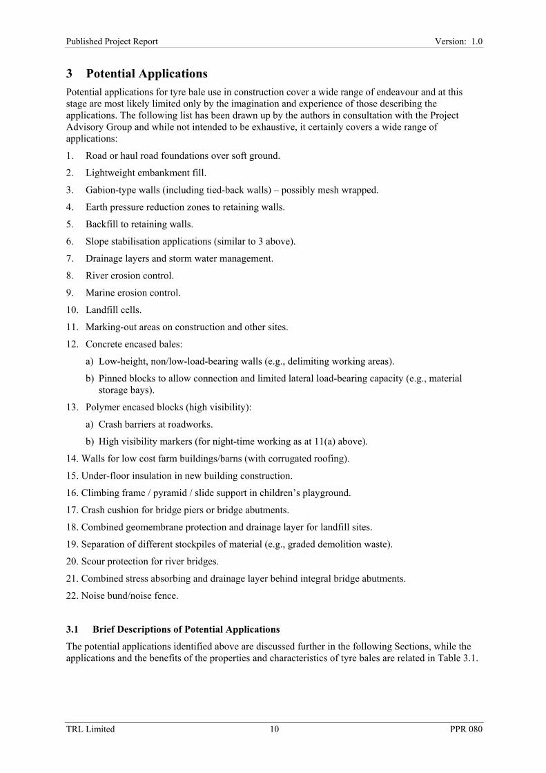
3.1.7 Drainage Layers and Stormwater Management
Excess water is a major contributor to many geotechnical problems. Tyre bales low down in an embankment will help to drain and strengthen soils above them. They are long-lasting, non-polluting and require less compaction than conventional fills. In virtually all the applications considered the self-draining or soil-draining properties of the blocks are an advantage.
3.1.8 River Erosion Control
Tyre bales are a low-cost option for protection of river banks. They are long-lasting and non-polluting. Typically sheet piles or rock-filled gabions are used to control river bank erosion. Both are considerably more expensive than tyre bales. Piles are held in place by insertion in the ground and gabions mainly by their self weight. Because of their light weight tyre bales would probably need some form of fixing in place.
3.1.9 Marine Erosion Control
As above, tyre bales are a low-cost option for the protection of beaches and soft cliffs. They are long-lasting and non-polluting. They can be employed in the construction of groynes but their low weight means that a solid fixing system is required wherever they are subjected to wave action. They can also be employed in pier protection and at sea to form artificial reefs or floating breakwaters.
3.1.10 Landfill Cells
Tyre bales are a good option for forming cells within landfill sites. As they have no sharp edges they may be placed directly on geotextiles or geomembranes with little danger of puncturing them, although a layer of sand may be required if the standard galvanised steel wire ties are used. Other types of straps are available on the open market, but care is needed to ensure that they conform to all safety requirements and are clearly marked with their load capacity. The bales can be placed in line and/or stacked up to form walls of various sizes. One or more faces can be coloured or painted with a number to aid identification of the materials contained.
3.1.11 Marking-Out Areas on Construction and Other Sites
On various working sites (e.g., for bulk earthworks) it is necessary to mark out the works. Traditionally painted barrels or posts are employed for this purpose. Should the site require bales as part of the permanent works the reuse of the marker in the works would be an excellent example of maximum recycling.

14TRL Limited 14 PPR 080
Published Project Report Version: 1.0
3.1.12 Concrete Encased Bales
Low-height, non/low-load-bearing walls (using concrete encased bales)
Bales can be encased in concrete. This provides blocks of constant size with orthogonal smooth faces. They will not have the same strength as a solid concrete block but will be sufficiently strong for many applications while the saving in cement and aggregate substantially reduces the cost compared with a solid block. While this improves the engineering properties and ease of use it moves away from the simple tyre bale concept.
Pinned blocks to allow connection and limited lateral load-bearing (using concrete encased bales)
The concrete encased bales can have fixings to permit the connection of blocks in a similar manner to temporary concrete barriers used at roadworks. This moves still further from the simple tyre bales concept.
3.1.13 Polymer Encased Bales (High Visibility)
Crash Barriers at Roadworks (Polymer Encased - High Visibility)
Another modification to the bale involves wrapping it in a high visibility coat (or a cheaper, less visible alternative is simply to paint the bale). While they would not meet the specification for temporary barriers for trunk roads they might be suitable for use in other locations. Again the wrapping process is moving away from the simple tyre bale concept.
High Visibility Night-Time Markers (Polymer Encased - High Visibility)
The high visibility bale (especially if wrapped in a highly reflective coat) would be useful as a night time marker. Again it would have to find non-trunk road applications and is some way from the simple tyre bales concept.
3.1.14 Walls for Low Cost Farm Buildings/Barns (with Corrugated Roofing)
This application would need careful placing of sand below each bale to maximise the stability of the walls. The good insulation might be of value for livestock in cold weather. Another possible advantage is that the structure could be taken down and rebuilt elsewhere or the bales used to make storage bays, improve boggy field entrances etc. without too much difficulty.
3.1.15 Under-Floor Insulation in New Building Construction
Bales could be employed to minimise heat loss through the floors of new buildings (or all round the basements of new buildings). Care would have to be taken that the excavation for the bales did not compromise the building foundations. Although highly insulating (when dry) the added complication and potential difficulties would probably lead builders to use traditional insulating materials.
3.1.16 Climbing Frame/Pyramid/Slide Support in Children’s Playground
Bales could not be employed uncovered where the public, especially children can readily gain access. A stepped pyramid, possibly supporting a slide could be constructed. All the tyre voids would need to be filled and the bales tied together for safety. A thick, heavy-duty geotextile would need to be firmly fixed, following the structure’s contours followed by, say, 100mm of seeded topsoil. Great care would be required with the design and its approval procedure because of the potential for danger to children playing.

15TRL Limited 15 PPR 080
Published Project Report Version: 1.0
3.1.17 Crash Cushion for Bridge Piers or Bridge Abutments
Bridge piers on highways are normally protected by a safety fence. Where a vertical concrete barrier is used this provides reasonable protection, even from a heavy goods vehicle. The more common steel safety fence provides little protection from errant heavy goods vehicles. Some piers have been strengthened to reduce the likelihood of damage. One or more tyre bales could be strapped to a bridge pier to help deflect or absorb some of the impact energy.
3.1.18 Combined Geomembrane Protection and Drainage Layer for Landfill Sites
A layer, or partial layer, of bales over a geomembrane would both protect the geomembrane from puncture and provide a good drainage path for the leachate from the waste. Some drainage systems may call for a combination of bales and whole tyres.
3.1.19 Separation of Different Stockpiles of Material (e.g., Graded Demolition Waste)
In stockpile yards piles of material often flow into one another requiring additional grading or separation before they can be used. Tyre bales could provide useful separating walls but would ideally require tying together to maintain stability
3.1.20 Scour Protection for River Bridges
Where scour around a bridge pier is expected a block of bales could be attached to the pier to reduce the velocity of the water and reduce scour. The main difficulty would be that scour occurs where flows are high in speed and volume. The bales are fairly light and would have very little stability by virtue of their mass thus the fixing detail would have to be very robust to ensure the security of the bales
3.1.21 Combined Stress Absorbing and Drainage Layer Behind Integral Bridge Abutments
Bridges up to 40m in length are now normally constructed as ‘integral bridges’ with the deck and both abutments cast as a single unit. This is because of all the difficulties of seized bridge bearings for conventional bridges where the intended movement of the deck relative to the abutments does not occur (producing an unintentional ‘integral bridge’). The winter to summer expansion of the deck (of the order of 5mm per abutment) is taken up in an elastic stress absorbing layer between the back of the abutments and the fill material. While the properties of the bales would seem to be appropriate for this purpose the small quantity of deformation needed and the huge maintenance cost should something go wrong means that existing, well tested stress absorbing materials will continue to be used.
3.1.22 Noise Bund/Noise Fence
Noise mitigation from highways, airports and other sources is of increasing importance. Where space is limited a noise fence is often the only suitable solution. However, where land is available a vegetated noise bund will generally be more attractive. The natural surface of the bale is likely to be a good noise absorber. For stability a high bund is likely to be pyramid-shaped in side elevation. If the bund is quite high and the area windy it will be necessary to tie at least the higher rows of bales together. Where the bund is visible to the public the face of the bales is not very attractive, and thus topsoil and seeding may provide a better face. (There may be difficulties with water retention in a dry summer to prevent the vegetation from dying.)

16TRL Limited 16 PPR 080
Published Project Report Version: 1.0
3.2 Selection of Applications for Further Study
Applications for further study were selected in consultation with the Project Advisory Group on the basis of a number of criteria. The criteria included that the chosen applications should be those most likely to be taken up in real construction projects and that they should be capable of using significant numbers of tyre bales.
The chosen applications are as follows:
• Road foundations over soft ground.
• Slope failure remediation.
• Lightweight embankment fill.
• Gravity retaining walls.
• Drainage layers.
• Storm water management systems and rainwater soakaways.
• Environmental barriers.
The properties and behaviours of tyre bales relevant to these applications are described in Section 4 and the design and construction approaches developed in Section 5.

17TRL Limited 17 PPR 080
Published Project Report Version: 1.0
4 Properties and Behaviour Tyres in the USA are generally larger than those used in Europe. Consequently tyre bales contain up to 17% fewer tyres in Europe than they do in the USA. While the same pressure is applied in the baling process, tyre size differences may have an effect upon the internal structure of the bales - most likely affecting properties such as stiffness and void tortuosity (and thus permeability). The significance of this impact upon the measured properties of tyre bales is relatively unknown, and while unlikely to be great, should be borne in mind when using test data from the USA.
4.1 Dimensions and Volume
The baling process produces a bale with nominal dimensions of 1.27m (50'') height by 1.50m (60'') width and 0.75m to 0.80m (30'') depth as it is completed and removed from the baling machine (see Figure B.9). On this basis the volume of a bale is a nominal 1.43m3 to 1.52m3.
Careful measurement of 24 typical tyre bales gives minimum, mean and maximum dimensions as shown in Table 4.1.
Table 4.1 – Tyre bale dimensions and volume.
Dimension Z (m)
Dimension X (m)
Dimension Y (m)
Volume (m3)
Minimum 1.28 1.51 0.79 1.55
Mean 1.30 1.53 0.82 1.63
Maximum 1.34 1.55 0.85 1.72
* Directions Z, X and Y refer to those represented in Figure 6.5 and are in the same order as those described in the preceding paragraphs.
However, all faces and corners of the bales are convex to a greater or lesser degree and the true volume of the tyre (the rounded edge shape rather than the cubic volume) has been estimated from immersion test of bales wrapped in plastic, to be closer to 1.17m3 (Simm et al., 2004). This means that around 18% to 23% (say 20% on average) of the nominal volume required to place a tyre bale comprises voids between the bales.
Roadscanners (2003) report that the effective size of the bales used in their project was closer to 1.50m by 1.50m by 0.85m, giving a volume of 1.91m3. However, these bales were manufactured, for various operational reasons, from a stockpile comprising a high proportion of larger tyres from four wheel drive vehicles and are not generally typical of what is likely to be produced from the UK tyre stock as a whole. However, given the variation in tyre bale stock and the fact that all faces are convex to a greater or lesser degree then measurements must be viewed as nominal and the need to fill gaps between the corners of adjacent bales is reinforced.
Typically the volume of tyre materials contained within a tyre bale, as opposed to the volume of the bale itself, is around 0.55m3 to 0.60m3 (Simm et al., 2004). This may be viewed as broadly equivalent to the volume component of specific gravity or particle density in soil mechanics terms.
4.2 Mass and Density
Measurements of typical tyre bales indicate that the mass ranges from 885kg to 890kg for a mix of mainly car tyres with a ‘few’ four wheel drive tyres. Using the detailed measurements in Table 4.1 the minimum, mean and maximum density are thus calculated as 0.515Mg/m3, 0.545Mg/m3 and 0.573Mg/m3.

18TRL Limited 18 PPR 080
Published Project Report Version: 1.0
Thus a nominal density, ρN, of 0.55Mg/m3 may be assumed. However, the true volume of the shape has been estimated to be closer to 1.17m3 (see Section 4.1 above and Simm et al., 2004) giving a true bale density, ρT, of 0.755Mg/m3 to 0.759Mg/m3.
During construction voids between the bales are usually filled with material such as sand or lightweight fill. This does, however, mean that the density of the bale mass, ρM, is not simply that of the bales themselves, but is also affected by the density of the surrounding fill material, ρF. The true volume of the bale is approximately 72% of the total volume occupied by a single bale and the surrounding fill (1.17m3/1.63m3). Thus the true density of the bale mass may be calculated simply from ratios, as follows:
( ) ( )FTM ρρρ 28.072.0 +=
Thus taking the true bale density, ρT, to be 0.76Mg/m3 and filling the voids between the bales with a material of bulk density, ρF, 1.600Mg/m3 gives a density for the mass, ρM, of 1.00Mg/m3.
Clearly this does not take account of any additional fill placed between layers of tyre bales. However, similar principles may be used to calculate the bale-fill density in these circumstances.
The specific gravity of tyre bales has been measured and found to be 1.07 to 1.14 in the USA (Zornberg, 2004) following estimates made by Zornberg et al. (2004) based on established data for tyre shreds.
4.3 Frictional Response
Simple tests to determine the friction between bales have been carried out by Simm et al. (2004). This involved placing two bales, each of known mass, one on top of the other. The lower bale was fixed in position and a horizontal force was applied to the upper bale to effect its movement over the lower bale.
The frictional constant, µ, was then calculated from the horizontal force required to move the upper bale divided by the normal force exerted by the mass of the upper bale on the lower bale. The value of µ was found to average 0.7 (range 0.64 to 0.74). In soil mechanics terms this corresponds to an angle of internal friction, φ, of 35o.
Further, more sophisticated, tests have been reported by Zornberg (2004). These involved an arrangement of three bales as illustrated in Figure 4.1. Specific advantages of this arrangement include that the test structure is inherently more stable and that the contact area between the fixed and the moving bale is constant. The results from these tests are reported in Figure 4.2.
Clearly the value of c is such that it would not normally be accounted for in design estimates. Indeed, it seems likely that the failure envelope curves at lower stresses effectively render c = 0. However, given that such curvature is likely to occur at stresses less than those imposed by the self-weight of a single layer of bales, then such stresses will occur only in exceptional circumstances. Such circumstances may include those in which water pressures induce a degree of uplift. It is unlikely that such circumstances would be relied upon for design purposes and taking c = 0 and the determined value of φ is conservative in this instance.
During the shear tests displacements at the front and back faces of the upper (or moving) bale were measured. Clearly the displacement at the back face indicates bale displacement and that at the front face indicates the sum of bale displacement and any compression of the bale that may occur. Shear failure was defined as the point at which the first slippage of the upper bale over the lower bales occurred. Prior to this point the displacements at the two faces were unequal, indicating that compression of the bale was indeed occurring. After failure the displacements became more or less equal, indicating limited further compression. Based on mean dimensions (Section 4.1) the strains experienced by the upper bale at shear failure varied between around 0.4% and 2.2%, with the majority being in the range 0.8% to 1.9%.

19TRL Limited 19 PPR 080
Published Project Report Version: 1.0
Figure 4.1 – Schematic showing the layout of shear tests reported by Zornberg (2004). The dimensions refer to Figure 6.5.
Figure 4.2 – Shear test results based on data reported by Zornberg (2004). Lines representing the normal stress imposed by the self weight of 1, 2 and 3 bales are shown, based upon the mean
measured dimensions and mass of a bales reported in Sections 4.1 and 4.2.
Y
Z
Normal Stress, σ
Shear Stress, τ
Fixed Bale Fixed Bale
Moving BaleFr
ont F
ace
Bac
k Fa
ce
Y
Z
Normal Stress, σ
Shear Stress, τ
Fixed Bale Fixed Bale
Moving BaleFr
ont F
ace
Bac
k Fa
ce
c = 1.5kN/m2; φ = 35.9o
8
10
12
14
c = 1.5kN/m2; φ = 35.9o
0
2
4
6
8
10
12
14
0 2 4 6 8 10 12 14 16
Shea
r St
ress
, τ(k
N/m
2 )
1 bale 2 bales 3 bales
Normal Stress, σ (kN/m2)
c = 1.5kN/m2; φ = 35.9o
8
10
12
14
c = 1.5kN/m2; φ = 35.9o
0
2
4
6
8
10
12
14
0 2 4 6 8 10 12 14 16
Shea
r St
ress
, τ(k
N/m
2 )
1 bale 2 bales 3 bales
Normal Stress, σ (kN/m2)

20TRL Limited 20 PPR 080
Published Project Report Version: 1.0
During these tests a degree of confinement was applied to the bales in the X-Z plane in order to attempt to simulate in-situ conditions. The degree of confinement was not measured but is estimated to be minimal.
4.4 Stress-Strain Response
An unattributed load test was carried out on an unconfined tyre bale. A maximum load of 1,500kN (780kN/m2) was applied during the test in the ‘Y’ direction (see Figure 6.5). This is very much higher than the loads or stresses to which the bales would typically be subjected in practice. In simple terms it can be taken that a 1m height of soil will generate a stress of around 20kN/m2. Thus a 3m soil above a blanket of bales would apply about 60kN/m2 to the bales and 780kN/m2 is equivalent to almost 40m of soil cover.
Apart from the unrealistic stresses applied during this test, one of the main problems with the test data is that the zero error was considerable with a 2% strain indicated at zero stress. The results from this test are not considered of use in terms of aiding practical design, other than to confirm that very high loads can be sustained by tyre bales without failure occurring.
Some results of tests to determine the load-deflection response of tyre bales have been reported by Zornberg (2004). The results of these tests have been interpreted to give estimated values for the Young’s Modulus (stiffness). Three types of test, all loaded in the Y-direction (see Figure 6.5), were reported and values are reported below:
• Three bales loaded vertically in the arrangement shown in Figure 4.1 with confining straps as described in Section 4.3. The calculated stiffness is around 980 MN/m2.
• As above but without the confining straps. The calculated stiffness is around 840 MN/m2.
• Two bales stacked one on top of the other and loaded vertically without the confining straps. The calculated stiffness is around 916MN/m2.
Each test was terminated at a maximum normal stress of around 28.5kN/m2 (equivalent to slightly in excess of the self-weight due to seven tyre bales) and the strains experienced by the tyre bales varied between around 3.0% and 3.5%. It was assumed that the full height of the loaded tyre bale was used in the calculation of stiffness and the values must therefore be considered as average values between the point of loading and the ground support below.
These data are considered provisional and it is hoped that finalised data will be published in 2006. In addition it is not entirely clear just how much confinement is provided by the use of straps, however from observation it is considered likely that the reported confined stiffness values underestimate those that might be anticipated in the field.
Further testing may be considered in the future to attempt to simulate field conditions. This may involve loading single bales located within realistic arrangements of bales and with the inter-bale voids filled with sand or other suitable fill materials.
4.5 Creep
An unattributed creep test was carried out on an unconfined tyre bale at a maximum load of 392kN (202kN/m2). Unsurprisingly at such extreme loads, the total strain was almost 27% after 72 hours. In common with the stress strain test reported above the loads and stresses applied were unrepresentative of those to which tyre bales are likely to be subjected in the field.
Zornberg (2004) reports that creep tests have been undertaken in both shear and compression. The shear creep tests were conducted in the arrangement illustrated in Figure 4.1 at constant horizontal stress levels of between 5kN/m2 and 16kN/m2. While Zornberg (2004) reports the total lateral displacement of the bale it is not clear how much of this relates to genuine creep compression and how much is simply gross lateral movement of the entire bale. Further analysis is thus not possible. It

21TRL Limited 21 PPR 080
Published Project Report Version: 1.0
is hoped that the test results will be published in a more definitive form in 2006 along with data from creep tests on two bales stacked one on top of the other and loaded vertically.
4.6 Permeability
The permeability of tyre bales has been measured in two planes (Simm et al., 2004), as follows:
• In the 1.50m by 1.27m plane, which gives an apparent pathway of around 0.75m the permeability was measured as 0.14m/s, broadly equivalent to that of gravel at around 0.1m/s.
• In the 1.27m by 0.77m plane, which gives an apparent pathway of around 1.50m the permeability was measured as 0.04m/s, broadly equivalent to that of very coarse sand at around 0.01m/s.
This assumes no obstructions to flow (i.e., no tortuosity of the voids). In practice, the water will have to flow around and between the tyres and will have a much longer pathway. The variation in the directional permeability was attributed to different degrees of tortuosity.
The tests were conducted in a high discharge flume and the differential head was clearly less than the height of the bales (approximately 1.5m in the configuration described in item (a) above and approximately 0.75m in item (b) above). The hydraulic head was thus determined in each case by the differential head and the apparent pathway.
It is important to recognise that the permeability of tyre bales can be reduced by deformation due to loading and to the ingress of sediment materials.
4.7 Porosity
The porosity of tyre bales has been measured (Simm et al., 2004) yielding results of between 50% and 56% for a standard bale. Simm et al. also measured effective porosity, the amount of interconnected pore space available for fluid transmission, as between 42% and 50%. They gave a comparison of tyre bale porosity compared with that of other materials as shown in Table 4.2.
Typically in applications where porosity is important it would be a replacement for coarse gravel. It is clear from the above that tyre bales have a higher porosity than gravel, although the permeability is very similar (see Section 4.6). This has been postulated (Simm et al., 2004) to be due to the high degree of tortuosity of the voids in the tyre bales which effectively slows down the passage of water through the bales.
It is important to recognise that the porosity of tyre bales can be reduced by deformation due to loading and to the ingress of sediment materials.
Table 4.2 – Porosity data for tyre bales and other materials (after Simm et al., 2004; Yu et al., 1993).
Material Total Porosity (%) Effective Porosity (%)
Range Arithmetic Mean Range Arithmetic Mean
Tyre Bales 50 - 56 53 42 - 50 46
Coarse Gravel 24 - 36 28 13 - 25 21
Coarse Sand 31 - 46 39 18 - 43 30
Fine Sand 25 - 53 43 1 - 46 33
Silt 34 - 51 45 1 - 39 20
Weathered Granite 34 - 57 45 Not Available Not Available

22TRL Limited 22 PPR 080
Published Project Report Version: 1.0
4.8 Durability
4.8.1 Durability Under Exposure to Ultra-Violet Light
Tyres can degrade under the action of the ultra-violet (UV) component of sunlight although carbon black, which is used to strengthen the rubber in tyres and aid abrasion resistance, serves to block the damaging UV rays.
Sulphur and zinc oxide are also used in tyres to prevent degradation by providing covalent bonding, allowing elastic deformation (Simm et al., 2004). The loss of these chemicals through leaching can thus accelerate the ageing process.
The rate of degradation is dependent upon a range of factors and largely unpredictable. However, for temperate climates there appears to be a broad consensus that five to ten years of exposure of tyres in direct sunlight would be required before significant deterioration, which might threaten the mechanical integrity of the tyre, would be encountered. It is important to note that such exposure is typical of neither the situation in which tyres are in-service on vehicles or of post-consumer tyre dumps where tyres at the surface are usually covered up rapidly by additional tyres. Where waste tyres have been used as silage clamps they are likely to have had significant exposure to sunlight and, therefore, UV. Such tyres are generally avoided by tyre balers as they often show signs of degradation and also of biological contamination. Notwithstanding this, there is a dearth of published information on tests to determine the effects of UV on tyres.
Post-consumer tyres should be stored out of direct sunlight and/or strong artificial light, in dry conditions at temperatures below 38oC (see also Section 4.10) where possible. Embrittlement and sidewall cracks in tyres exposed to air and sunlight have been reported after around five years and ten years respectively, usually in climates subject to high levels of sunlight. The use in bales of tyres already degraded by UV light to the point where the rubber has become ‘brittle’ (flaky, light grey/black or brown and easily split) should be avoided, as there is a strong possibility of their breaking up under handling and/or compression.
Like tyres, tyre bales should not be stored in sunlight for excessively long periods prior to use and once incorporated into construction works should be covered up to prevent UV-degradation and leaching of sulphur and zinc oxide (aesthetic considerations will ensure that this rarely if ever becomes an issue).
Simple precautions in the form of minimising the exposure of tyres and tyre bales to sunlight, of rejecting tyres showing signs of deterioration, and of burying tyre bales once installed into construction work must be followed. In such circumstances UV degradation is considered to be unlikely to be a major problem affecting tyre bales, however confirmation of the time range at which UV exposure may become a problem is viewed as a research priority.
Studies of the deterioration of geosynthetics on exposure to UV (e.g., McGown and Al-Mudhaf, 1994) indicate that such deterioration is strongly dependent upon material type, the prevailing climate (and thus the actual level of UV exposure) and the level of temperature cycling. The latter two factors would both be expected to be considerably more severe in hot, dry climates than in the relatively benign and stable conditions experienced in the UK. While climate change may have an effect on ambient temperatures and UV radiation it seems unlikely that the small changes forecast for the UK over the coming years will cause a dramatic shift away form this pattern. Studies of geosynthetic deterioration once buried in the ground have been conducted over periods of seven years (Liu et al., 1994) and 13 years (Sprague et al., 1994). The results of these studies indicate that degradation of the materials studied over these periods is negligible. Indeed, McGown and Al-Mudhaf (1994) indicate that the effects of burial in stabilising the temperature cycling may contribute to the lack of degradation of such materials once buried. Clearly such results are not directly applicable to tyres although they may be viewed as providing a pointer to the form of the research required and possibly to the potentially limited scale of the problem.

23TRL Limited 23 PPR 080
Published Project Report Version: 1.0
4.8.2 Durability of Buried Tyres
While information on the deterioration of tyres once buried in the ground is limited there is some evidence of tyres having been excavated from US landfills after 50 years in apparently good condition (Zornberg et al., 2004). Indeed, 60,000 tyres that had been buried and partially submerged on the shore of Lake Superior for a period of up to 40 years were removed in 1989 and inspection of the tyres revealed no visible signs of degradation (Drews, 2006).
Consultations with key rubber and tyre research organisations that might be expected to hold information related to the degradation of tyres when exposed to UV and when buried in the ground has failed to yield any information additional to that reported above.
Clearly there is a need for further research on this issue. The form of such research might usefully be steered by previous work on the degradation polymeric geosynthetic materials due to exposure to UV and also once buried in the ground.
4.9 Contamination Potential
Hylands and Shulman (2003) summarise the results of laboratory and field studies to determine the level of leachates from tyres. The test results indicate that for all regulated metals and organics the results for post-consumer tyres are well below regulatory levels.
Substances which could potentially leach from post-consumer tyre materials are already present in groundwater in developed areas. Studies suggest (Hylands and Shulman, 2003) that leachate levels for the majority of contaminants fall below the allowable regulatory limits and will have negligible impact on the general quality of water in close proximity to tyres.
Test results (see Hylands and Shulman, 2003) further indicate that tyres do not leach volatile organic compounds. Research on long-term safety indicate that most of the compounds detected in water samples are at or near detection limits at only trace levels, 10 to 100 times less than regulatory limits for drinking water and therefore, do not pose a threat to health or the environment.
It must be appreciated that by far and away the majority of the work conducted on water quality relates to tyre chip or shred. In such case the surface area available for chemical reactions and leaching are significantly greater than for whole or baled tyres, but reinforcing materials will also be exposed. Both factors may be expected to increase the potential for contamination, and thus work conducted on chips and shred may be viewed as conservative when applied to the use of whole and baled tyres.
Work by Todd and Watts (2004), as part of a project on shredded tyre provides more practical and useful information on chemical degradation. Zinc is used to galvanise the wires in the tyres, and the shredding has resulted in increased zinc concentrations being noted in ground water adjacent to tyres especially where the water is hard. Work in the USA (Humphrey, 1996b; Gray, 1997) encourages the use of tyre shreds as a filter material but recommends that they are used above the normal water table. Other contaminants (such as hydrocarbons) may be leached from the tyres but the concentration levels are so low that they may be disregarded - this last is interesting as rubber tyres, particularly crumbed rubber, are recognised as having high potential for the absorption of organic contaminants. More work is required to be definitive.
There may be a concern regarding the potential use of tyre bales in applications below the ground water table and in other situations in which they may be filled with water that remains static. Such situations may include landfill and drainage applications. However, it may be considered only relatively small increases in the chemical concentrations in leachates will be caused by the presence of tyres bales as part of engineering measures. Such increases may be acceptable, especially in situations where such leachate is abstracted and treated. Work reported by Collins et al. (1995; 2002) indicates that leachate from tyre chips was within regulatory levels and for whole tyres used in a marine environment that leachate occurred from the outer surface of the tyre, a few microns deep, and rates of release then decreased with exposure time.

24TRL Limited 24 PPR 080
Published Project Report Version: 1.0
The applications proposed by this report for tyre bales are not thought to pose any significant concerns in respect of increasing the concentrations of chemicals passing through the structures. Notwithstanding this the authors would welcome the opportunity to monitor the outflow from, for example, a storm water drain or a soakaway in order to confirm this perception experimentally.
Data on leachates from tyre shred and chip were used in an evaluation of the contamination potential of tyre bales in the USA (Haider, Undated). Following separate evaluations SEPA declared that baled tyres are unlikely to cause pollution to groundwater and the Fisheries Research Services Marine Laboratory stated that it would be happy to see an application made to use tyre bales as infill materials behind well-engineered rock armour for coastal protection works.
4.10 Fire Resistance
Sonti et al. (2000) have pointed out that whole tyre dumps can pose a fire risk and report fires in Lincoln, Nebraska; Hagarsville, Ontario; Catskill, New York; and Rheinhart, Virginia (see also Section 2). While there is no suggestion that spontaneous combustion is likely in dumps containing whole tyres, indeed Hylands and Shulman (2003) describe the spontaneous combustion of whole tyres as unknown, such dumps are vulnerable to carelessness or arson as exothermic oxidation reactions create conditions that may favour combustion.
Due to the air pockets that are within tyres and tyre dumps it is extremely difficult to put out fires and some have burned for months. Air pollutants from tyre fires include toxic gases such as poly-aromatic hydrocarbons (PAHs), carbon monoxide, sulphur dioxide, nitrogen dioxide and hydrochloric acid. In addition oils related to the gaseous compounds indicated above may also leach into groundwater resulting in severe pollution, potentially including to drinking water aquifers.
The shredding of tyres has become a popular approach to the recycling of tyres partly as it reduces the mosquito problem (see Section 2.1) and also reduces the entrapment of air, generating a potentially viable engineering material in the process. The process does, however, expose the steel elements in tyre construction and also increase the surface area of the rubber elements. As both steel and rubber are subject to exothermic oxidation reactions and the rate of chemical reactions is directly proportional to surface area it can be seen that the potential for combustion may have increased considerably despite the reduction in available air and therefore available oxygen.
Prior to 1997 three of the 70 known tyre chip fill applications in the USA had experienced problems with exothermic oxidation reactions that had generated fumes and even the burning of tyres. Three main mechanisms for the spontaneous combustion of tyre fires were proposed by Humphrey (1996b), as follows:
1. Oxidation of exposed steel wires, an exothermic reaction.
2. Oxidation of tyre rubber, also an exothermic reaction.
3. Microbes consuming the exposed steel elements of the tyre and generating sulphuric acid which in turn lowered the pH. If the pH reached a value of four or less then the exothermic oxidation of the steel would have been accelerated.
In addition, hydrocarbons, from fuel spillages for example, can cause exothermic reactions as microbes are consumed. It is also known that wet conditions such as following heavy precipitation or flooding can increase the rate of temperature increase resulting from the exothermic reactions described above.
Three tyre shred fires in Garfield County and Il Waco in Washington State and in Glenwood Canyon in Colorado were reported by Humphrey (1996b). They may be broadly categorised as large deep masses of tyre shred with little or no provision for generated heat to escape and a plentiful supply of oxygen from below, usually from a rockfill drain or similar. Design guidelines for the minimisation of heating of tyre shred fills were also developed (Humphrey, 1997).
Further work, by Nightingale and Green (1997), investigated whether a Japanese theory of spontaneous combustion of tyre shred could be used to explain the fill fires in the USA. The theory

25TRL Limited 25 PPR 080
Published Project Report Version: 1.0
stood up well to this test and indicates that an elevated risk of the spontaneous combustion of tyre shred begins at around 20oC with combustion at around 70oC for a 3m layer of 400kg/m3 shreds while for a 6m thick layer an elevated risk begins at around 10oC with combustion at around 60oC.
The risk of spontaneous combustion from whole tyre dumps is believed to be extremely low, albeit that prevailing conditions may favour combustion when aided by outside interference (e.g., sparks from agricultural machinery, lightning and arson). Tyre shreds expose a greater surface area of both rubber and steel thereby increasing reaction rates substantially provided that sufficient oxygen is available. On the other hand the manufacture of whole tyres into tyre bales not only reduces the available air (the volume reduction in the manufacture of a tyre bale is around four or five to one), and therefore oxygen, but also reduces the available surface area by creating multiple and extensive contacts between the individual tyres forming the bales.
The perceived likelihood of spontaneous combustion of tyre bale monofills due to ambient environmental conditions is further reduced by reference to experience. In both Kansas and Colorado tyre bale monofills, containing more than 10 million tyres in baled form, have been stored both above and below ground for more that 9 years. Both states experience prolonged periods during the summer months when temperatures reach in excess of 100oF (38oC) and there have been no combustion problems or incidents (Drews, 2006). It is concluded that the risk of spontaneous combustion of tyre bales is negligible.
This conclusion has been supported by tests carried out by the Fire and Risk Sciences Division of the Building Research Establishment and reported by Simm et al. (2004). Isothermal self-heating tests were carried out and it was concluded that a volume of tyre bales 10 bales long by four deep and four high would be very ‘sub-critical’ when stored in this volume and geometry at an ambient temperature of 35oC. This arrangement would not become ‘critical’ until an ambient temperature of 188oC was reached and would then take 39 days before it ignited. Similar determinations were carried out for other arrangements as detailed in Table 4.3.
The time to ignition of tyre bale structures is typically of the order of 40 days or more when the tyre bale mass is held at an ambient temperature something in excess of 180oC. While typical construction installations are likely to endure for considerably in excess of 40 days the ambient temperature required for self-heating to be initiated is far in excess of what might be reasonably anticipated. If each tyre bale was surrounded by a non-combustible layer of aggregate material and could thus be taken as a single entity then the bale would not become critical until an even more extreme temperature of 224oC was reached. Ignition would be expected after a period of 2.3 days at that sustained temperature. It should be noted that the encapsulation of individual tyre bales or tyre bale layers is not generally recommended as this approach can introduce potential shear planes (Prikryl et al., 2005; Winter et al., 2005b). This is particularly the case if site-won plastic soil materials are utilised for this purpose. However, it is recognised that such layers have the potential to conduct heat away from tyre bales, still further lowering the risk of spontaneous combustion. If such an effect is required, in for example large masses of tyre bales, then the material used should be a close match in terms of frictional properties to the tyre bale-to-tyre bale friction (see Section 4.3).
Table 4.3 – Calculations of tyre bale critical ignition temperatures and times to ignition.
Tyre Bale Usage Dimensions Critical Ignition Temperature (oC)
Time to Ignition
Storage 17.5m by 6.0m by 3.0m 188 39.0 days
87.5m by 6.0m by 3.0m 185 50.4 days
Pevensey (see also Simm et al., 2004; Winter et al., 2005b)
21.0m by 7.5m by 3.75m 182 65.4 days
Single Bale 1.75m by 1.5m by 0.75m 224 2.3

26TRL Limited 26 PPR 080
Published Project Report Version: 1.0
Having concluded that the risk of spontaneous combustion of tyre bale masses is negligible there are a number of simple engineering measures that may be applied to ensure that conditions that could lead to favourable conditions for sparks, lightning or arson are minimised. These measures are as follows:
• The use of contaminated tyres and bale should be avoided from a basis of pollution protection and any contaminated bales, particularly if the contamination is in the form of hydrocarbons, should be returned to the supplier.
• Limiting the depth of tyre bale lifts to 3m (10') has been recommended in the USA. This is based upon the recommendations of Humphrey (1997) for tyre shred and is grossly conservative for tyre bales. The use of a high friction layer every 3m height of tyre bales is likely to have the benefit of providing a regulating layer to take up any minor irregularities in the surface providing a more competent structure.
• In order to prevent ingress of plant roots to the bale mass creating a potential pathway for chemical spills and water and to keep the bales well away from potential sources of combustion, a minimum of 1m cover of inert soil material is recommended.
• The presence of water in the bale mass is inevitable and it is not entirely clear to what degree this will increase the heating and ignition rates determined by Simm et al. and reported above.
Monitoring of the heat generated in tyre bale masses is recommended in order that such concerns can be fully dealt with in future.
Further test on the ignition properties of tyre bales were reported by Simm et al. (2005). An initial test involved attempting to set fire to the corner of a tyre bale, a point that it was felt likely that arsonists might target. The test was unsuccessful in igniting the tyre such that it burnt in a self-propagating fashion (i.e., the fire went out as soon as the source of the fire was burnt out). A second test involving the setting of a fire inside the rim of one of the external bale tyres, a seemingly unlikely target for vandals, was more successful in that a self-propagating fire was achieved. However, the fire took more than 15 minutes to reach that point. In addition, some have questioned the validity of the test as two of the tie-wires broke during the test presenting a more open bale structure that may have been easier to ignite.
The likelihood of spontaneous combustion of tyre bales is concluded to be negligible. While any combustion is likely to be as a result of arson it has also been shown that igniting tyre bales is a difficult exercise in itself and such a successful arson attack on tyre bales would require a high degree of determination on the part of the arsonist.
4.11 Human Health and Safety
Guidelines were prepared for workers who come into contact with post-consumer tyres during processing and use by Hylands and Shulman (2003). These have been adapted to be pertinent to tyre baling operations in the paragraphs below.
There are no permanent effects from physical contact with the tyres in whole, shredded, chipped or granular form. For most potential irritations, normal protective wear is sufficient.
All workers who come into contact with raw materials and tyre baling machinery should wear protective clothing including: steel reinforced boots; eye, ear and head protection; and protective gloves. Additionally workers in the proximity of cutting, shredding and chipping equipment should wear dust masks.
All workers should wear long sleeves and long trousers at all times. The most enduring known risks from tyres in the workplace are strains and sprains from manual handling. As each completed tyre bale may weigh up to one tonne manual handling of tyre bales should never be attempted.
Additionally it is important that proper procedures be followed during tyre bale manufacture. The procedures described in Appendix B have been carefully developed in collaboration with tyre bale manufacturers with a view to describing working processes that are as safe as may be reasonably

27TRL Limited 27 PPR 080
Published Project Report Version: 1.0
practicable. It is, however, the responsibility of those parties involved with tyre baling and in the use of tyre bales to ensure that appropriate risk assessments are undertaken and acted upon and that full account is taken of the requirements of the relevant legislation and regulations.

28TRL Limited 28 PPR 080
Published Project Report Version: 1.0
5 Application Guides In this section information intended to allow the design and construction of various types of structure is presented in the form of a series of application guides. The information presented has generally been restricted to that required to take account of the use of tyre bales in a given application. The reader is referred to local codes, standards and specification for areas not covered. This has the advantage of rendering the information presented broadly non-specific to practice in a specific country.
In some cases it has proved possible to develop a design procedure on the basis of existing and well established techniques. In other cases the lack of any rigorously derived information on, for example, the stiffness of tyre bales has meant that the design methods presented are based upon precedent and experience, forming a guide to construction rather than a formal analysis-based design method.
The information presented is generally specific to the use of tyre bales in the given applications. It is important that design is undertaken, and construction overviewed, by appropriately qualified and experienced engineering personnel.
General issues that apply to a number of tyre bale applications, such as the alignment and layout of the bales, their durability and fire resistance are dealt with in Section 6. They are only referred to in this chapter when they are of particular importance to the application under consideration.
5.1 Road Foundations Over Soft Ground
The construction of roads over soft ground such as peat has long presented technical challenges. These are often magnified by the fact that many such roads carry only low traffic flows and must therefore be constructed and maintained within limited budgets. Road construction over soft ground is explored further by Winter et al. (2005a).
Temporary surcharging of newly constructed roads has been employed in an attempt to consolidate and strengthen the subsoil in both Scandinavia and parts of Sutherland in Scotland. Typically two metres of fill material has been placed to surcharge the road for several weeks and after some consolidation of the subsoil, the fill is removed and the surface regulated and repaved. The success of such an approach is often limited in very soft soils such as peat due to the likelihood of long-term secondary consolidation.
If the depth of peat or other soft material is shallow then removal is often an option. The excavated material is then replaced by more competent materials which may include tyre bales. However, this does leave the issues of disposing of the excavated material and preventing the adjacent material from flowing into the excavation. The resolution of either or both of these issues can prove costly, and such costs will increase rapidly with the depth of material excavated.
Where the layer of soft material is sufficiently thick to preclude removal alternative solutions using lightweight materials are needed. The use of lightweight tyre bales as a foundation material has the potential to provide such solutions.
There are essentially two approaches to construction of roads over soft ground: above ground or ‘floating’ construction and below ground construction (Figure 5.1). Both conventionally use large volumes of granular fill.
5.1.1 ‘Floating’ Construction
In areas of deep soft soil replacement techniques are unattractive as large volumes of material must be excavated, transported and disposed of with the consequential effect on costs. The surrounding soft material may create technical difficulties related to excavation support, basal heave and other factors, making the proposed project difficult if not uneconomic.

29TRL Limited 29 PPR 080
Published Project Report Version: 1.0
Where the natural surface ‘crust’ is stiffer than the lower layers due to vegetation, desiccation, compaction and other factors the surface may be suitable for use as the road foundation. Care is needed to ensure that the crust is not broken or otherwise compromised during construction and that as the road is built the imposed loads are spread over as wide an area as practical. Historically, various materials have been used to enhance the ‘crust’ effect and spread loads. The shallow embankment on which the Airedale Railway runs through Bingley in Yorkshire is constructed over a peat bog with bundles of faggots and sheep pelts placed on top of the peat to spread the load of the embankment (Osborne, 2005).
Figure 5.1 – Schematic illustrating the differences between ‘floating’ and buried construction.
Above ground construction has often utilised bundles of twigs, called fascines, placed at subgrade level to provide resistance to differential movement. Often these were orientated at 90o to one another in two layers. On constructions designed to take higher traffic flows logs were used above the fascines. This generally worked best where a stiffer material, such as fibrous peat, overlay less competent material, such as amorphous peat. The modern equivalent is a geosynthetic material often with a sand regulating layer. The use of tyre bales on top of the geosynthetic/sand layer further allows the applied load to be lessened.
5.1.2 Buried Construction
The removal of in-situ materials and replacement with new, preferably lightweight, materials is undoubtedly a more expensive option. However, due to the lateral restraint provided by the excavation boundaries a more durable construction is likely. The key to such construction lies in ensuring that the new material adds as little load as possible.
Buried construction may be preferred in more competent materials, or shallow poor materials for which removal is an option. Such materials include normally consolidated silts and clays, and soft predominately mineral soils for example. A geotextile is a key element in spreading the foundation load as for above ground construction.
The repair or reconstruction of an existing road over soft ground presents particular problems. Often the repair is required as a result of differential settlement. The road materials will have settled giving an uneven surface, poor ride quality and an increased risk of flooding. The placement of additional material to raise and regulate the pavement surface is simple but will increase the loading on the formation and almost certainly cause additional differential settlement. The replacement of the existing material is thus a necessity.
Floating Construction
Mass of construction is additive
Risk of settlement
Surface ‘crust’ remains intact
Buried Construction
Mass of construction is not additive
Lesser risk of settlement
Surface ‘crust’ breached
Floating Construction
Mass of construction is additive
Risk of settlement
Surface ‘crust’ remains intact
Buried Construction
Mass of construction is not additive
Lesser risk of settlement
Surface ‘crust’ breached

30TRL Limited 30 PPR 080
Published Project Report Version: 1.0
5.1.3 Design Approaches
Low-volume tyre bale roads have been successfully constructed both above and below ground (see Winter et al., 2005a; 2005b). A geotextile separator has been used between the in-situ soil and the tyre bales, often with a regulating layer of sand. The geotextile is particularly important to prevent differential movement of the bales during and after construction.
The construction and rehabilitation of low-volume roads over soft ground represents one of the most promising applications for tyre bales. There is currently insufficient information to justify their use with higher traffic levels (in excess of a few hundred vehicles per 24 hours, 2-way Annual Average Daily Traffic). When more information and greater experience are available it may be possible to incorporate tyre bales in foundations for higher traffic flows.
One of the key design decisions is whether the construction should be above ground (floating) or below ground (buried). The former exploits any stiffer layer that may exist close to the surface, while the latter exploits the lateral support available from the in-situ materials and has the potential to limit the additional loads placed on the subgrade. Thus the designer needs to consider which approach is most suitable for the given circumstances.
Analytical input for low-volume road design on soft ground is usually limited. Setting aside economic factors, this is because the strength and stiffness properties of the soil involved are usually at or close to the lower limit of what can be measured, rendering the analytical input parameters subject to wide error ranges. In addition the sampling process tends to disrupt the soils structure leading to lower values than might exist in the field situation. Accordingly many such roads are designed on the basis of experience and on a specification-led basis. Notwithstanding the foregoing an assessment of the depth and variation in the properties of soft materials, such as peat can be extremely valuable in targeting the precise construction approach. Useful information on the use of the Mackintosh probe for this purpose is given by Clayton et al. (1982) and Fakher et al. (2006).
The following sections describe the main construction steps and offer guidance based upon experience of successful projects of emerging good practice in constructing low-volume roads over soft ground using tyre bales.
5.1.4 Excavation and Preparation
If the construction is to be buried, or partially buried, then excavation is the first construction activity.
The minimisation of stresses applied to soft ground by the use of low ground-pressure plant driven on wide tracks is to be preferred as is working in dryer weather when the moisture content of the soil is at a minimum and strength and stiffness are maximised. The plant should be driven carefully to the start of the excavation to ensure that the surrounding soil formation is not unnecessarily damaged.
A suitable geotextile should be installed either at ground surface level or in the excavation followed by a regulating layer of sand if required. Provision should be made so that all geotextile-to-geotextile interfaces incorporate an overlap of 1m. The use of a geotextile is considered good practice and has a number of advantages including aiding working conditions in soft soils, strengthening the structure by tying together the assembly of bales, and separating the bales from the subsoil and thus preventing the ingress of fines.
Construction in cells is recommended to minimise the size of the excavation as is rapid construction of each cell. The exposure of the soil to the weather and the likelihood of side slope failure are thus minimised. Bale sizes mean that excavations are unlikely to exceed 1m but close attention should be paid to the possibility of sidewall collapse and associated hazards to workers during the risk assessment and the execution of such operations.
Randomly orientated, bonded, non-woven geotextiles such as those manufactured by Typar have been found to be effective. It is however important to note that a geosynthetic should never be specified by manufacture and/or product but always by the properties required. Their main function is separation with strength and resistance to clogging the most important properties.

31TRL Limited 31 PPR 080
Published Project Report Version: 1.0
Geotextile design procedures should reflect local standards. Detailed procedures for design of the required burst and puncture strength are given by John (1987) and Koerner (1990) for example. In respect of criteria against the clogging of non-woven geotextiles O90 > 2d15 and a geotextile porosity of greater than 30% are often specified (e.g., OECD, 1991; MCHW 1).
Where the soil is not excessively soft or where tree roots or similar provide some support it may be possible, with care, to omit the geotextile.
The geotextile should be placed in the base of the excavation, perpendicular to the line of the road. Sufficient excess should be allowed at either side to allow the bale assembly to be completely wrapped in the geotextile with a 1m overlap.
As a general rule, the fewer joints or overlaps present in the geotextile then the more resilient will be the finished construction. Geotextiles can be readily obtained in 4m or 5m wide rolls and can be handled with relative ease on site.
The foregoing is predicated upon buried construction being the preferred approach. However the basic principles set out are similar for floating construction. The key difference is to ensure that no unnecessary damage occurs to the in-situ soil formation as a result of the construction works. Such damage can, if sufficient, lead to the formation being compromised and causing difficulties with differential settlement. The geotextile should be relatively easy to install as the need to ensure that it fits into the excavation is removed.
If an existing road is being replaced then the opportunity exists to minimise both the costs of the new construction and its environmental impact by reusing as much of the existing material as possible. It is often possible to process the existing materials to sizes suitable for use in either the construction of the new pavement (Section 5.1.7) or of the drainage system (Section 5.1.8). This can be an important consideration as low-volume roads such as these are often constructed and maintained with very limited budgets. Any savings in material costs that can be made can only be of benefit. It should however be noted that it is unlikely that existing pavement materials could be economically processed on site to provide the fine fill described in Section 5.1.6.
5.1.5 Placement and Alignment of Bales
It is recommended that the bales are laid in a simple chessboard pattern with the tie-wires aligned along the length of the road and the shortest dimension forming the vertical (see Section 6.3). A loggers clam has been found to be an effective means of handling tyre bales (see Section 6.2), allowing them to be rotated easily into position. In general, the bales should be placed as close together as possible and, preferably, ‘butted-up’ together, in order to maximise the potential friction between the bales. The potential for differential settlement of the subgrade is thus minimised as is the amount of fill needed between the bales (see Section 5.1.6). Figure 5.2 shows an example of a construction in which the bales have been placed too far apart.
A row of four bales will thus yield a 6.0m nominal width for the tyre bale construction. As low-volume roads often have an unbound surface it is customary in many parts of the world to construct the road wider than is normal. As such a road width of five bales (nominal 7.5m width) or even six bales (9.0m nominal width) is recommended for two-way traffic. Certainly the width of the foundation should be at least two bales wider than the completed road surface to maximize load spreading. Other considerations (land availability, cost, soil strength, etc) may encourage greater or lesser widths based on engineering judgement.
A regulating layer of sand is normally required between the geotextile and the tyre bales. This achieves a degree of regulation against small variations in level in the base of the excavation, if the construction is buried, or in the existing ground surface, if floating construction is planned. Similarly, the omission of a regulating layer or the provision of one with minimal depth above the geotextile will provide maximum economy and minimum weight. Practical plant operating requirements may be the deciding factor especially if a load spreading or protective layer is needed.

32TRL Limited 32 PPR 080
Published Project Report Version: 1.0
The rows of bales should be placed across the width of the road. When the rows reach to about 1m from the far edge of the geotextile a second geotextile sheet should be overlapped beneath the first. More rows of bales should be added until they rest on the second sheet.
Figure 5.2 – Construction in which the bales have not been placed as close together as possible and in which the voids between the bales have not been well filled.
One or more rows of bales should be added until they start to sit on the second geotextile sheet.
The foregoing assumes a single layer of bales is to support the road. If two or more layers are required then the second layer should be placed on top of the first, stepped in at either side to provide around half a bale width of overlap. This is similar to constructing a shallow embankment comprising just two layers of bales. For further information on tyre bale embankments refer to Section 5.3.
5.1.6 Filling of Voids
The sub-rectangular shape of tyre bales means that voids remain at the corners of each bale even when they are butted up against one another. In practice small gaps are sometimes left between adjacent bales although every effort should be made to ensure that these are minimised (see Section 5.1.5). Figure 5.2 shows an example of a construction in which the gaps between the bales have not been minimised and then not fully filled. To maximise the stiffness and stability of the structure the voids must be filled. This also has the effect of helping to maximise the friction between the bales and thus minimise the potential for differential settlement of the subgrade (see also Section 5.1.5). Coarse sand has been used successfully as have single-sized aggregate pellets. Crushed glass of a suitable grading may be less likely to clog or arch than sand when wet.
The most effective method of ensuring that the voids are filled has been found to be to use a bulldozer to apply a 150mm to 300mm layer of the material to the upper surface of the bale layer (Figure 5.3) and then to apply a vibrating roller to the layer to vibrate the fill into the voids (Figure 5.4).
If the fill becomes wet or clogs the voids applying water using a bowser may unclog such areas. Note that both very dry and very wet sand will generally flow efficiently, but that it is generally easier to add than remove water, at least in a temperate climate.
The fill material will affect the density of the structure as noted in Section 4.2. The voids have been estimated to take up 20% to 25% of the nominal rectangular bale volume. This must be allowed for in calculations of, for example, bearing capacity. The effects of regulating layer(s) above or below the tyre bale layer must also be taken into account.

33TRL Limited 33 PPR 080
Published Project Report Version: 1.0
Stretcher bond and staggered layouts are not recommended (see Section 6.3). However, if these are used then special attention must be paid to the infilling of the castellation voids at the bale mass edges. Dry sand is neither suitable nor required and conventional crushed rock fill is more likely to be suitable for this application.
Figure 5.3 – Placing material to fill the voids between the bales. (Photograph © Chautauqua
County Department of Public Facilities.)
Figure 5.4 – Vibrating material between the bales and compacting the layer above the bales.
(Photograph © Chautauqua County Department of Public Facilities.)
Once the fill operation for a cell has been completed for a section of road the geotextile should be wrapped around the bale-fill composite with an overlap of around 1m. A crushed rock sub-base should be placed and compacted on top of the completed section. A thickness of 150mm is likely to be sufficient to provide a construction platform for the works to continue without damaging the geotextile. The final thickness of sub-base must be assessed to ensure sufficient capacity during normal use and should be the subject of site-specific design.
After the completion of these operations the construction may proceed to the next cell to continue the process described above until the required length of road has been completed.

34TRL Limited 34 PPR 080
Published Project Report Version: 1.0
5.1.7 Pavement Construction
Pavement thicknesses must be determined from traffic flows and type, foundation conditions and the material used to form the pavement layers. Experience in the USA is of tyre bale roads with AADT 2-way flows of between 200 and 1600 vehicles per day.
Local methods of determining pavement thickness are likely to prove most suitable. However, total pavement thicknesses between 250mm and 450mm have been employed. The 250mm thick pavement employed an A252 welded reinforcing mesh (8mm bars at 200mm centres) to help stiffen and strengthen the pavement.
In the USA three 150mm layers of crushed gravel sub-base type material have been used to form the pavement and bituminous layers added on top if required. If an unbound road surface is required then a suitable rock surfacing layer must also be added. Similarly, if a bituminous pavement surfacing is required then the requisite layers must be added. The precise type of pavement will depend on local standards and requirements.
The low traffic flows associated with such pavements yield an excellent opportunity to maximise the use of reused and recycled materials, either from off-site or from the reconstruction of adjacent sections of road.
If an unbound pavement surface is used then re-grading after any initial differential settlement is a relatively inexpensive operation compared to the equivalent operation for a bound surface. However, it should be pointed out that the use of unbound roads, in the UK at least, is at best unusual and likely to be considered only for those roads with very low traffic flows. Bituminous layers, where required, are usually added at a later date after initial differential settlement of the unbound layers under traffic has occurred and suitable adjustments have been made to the profile. This presents a lower risk to the bituminous materials by lessening the risk of it suffering excessive deformations which would be costly to correct.
5.1.8 Drainage
Cross falls and drainage provision would be in line with local climatic conditions and standards.
Cross falls in particular are critical to the efficient shedding of water and to preventing water ingress to an unbound construction. Experience in the northeast USA indicates that cross falls between 1 in 24 and 1 in 16 have been found to be effective. This is however no guarantee that they will be effective elsewhere. In the same region cross falls of 1 in 32 have been used and found to be effective.
Drainage provision should take account of both current needs and emerging needs in terms of perceived climate change. In Scotland, for example, the current design return period for rainfall events is likely to be raised by a factor of two.
Additionally, the high porosity and permeability of tyre bales means that edge drainage is critical and should form an integral part of a design incorporating tyre bales in a road foundation, especially at bends and even more so at banked bends. Care is needed especially with roads founded in peat that the drainage is of the road and not of the surrounding wetlands which may be damaged if drained excessively.
5.1.9 Successful Applications
Successful applications involving the construction of tyre bale road foundations have been achieved in both the USA (New York State) and the UK (see Winter et al., 2005b).
Chautauqua County Department of Public Facilities has completed five projects using tyre bales as a lightweight subgrade replacement for roads over soft ground (Figures 5.2 and 5.3). The tyres result from the clean up of a tyre dump and from a tyre amnesty programme (see Section 2). A further project is planned for 2005. Future projects of this nature will depend upon the availability of tyres for baling (Anon, 1998; 2001).

35TRL Limited 35 PPR 080
Published Project Report Version: 1.0
The geology of the County is characterised by sands and gravels in the river valleys with glacially deposited fine silty clays elsewhere, primarily on the hilltops which are often depressed forming high level swamps. These materials are stable if kept dry but are very sensitive to moisture and more so to the freeze thaw cycle which can turn them to a material not dissimilar to pottery slip and are capable of turning conventional roads constructed on them into impassable quagmires. It is on these relatively high level roads that the County Authorities have targeted tyre bale road construction.
To date with the roads having been in service for up to six years no major signs of distress have been observed that could be attributed to the presence of tyre bales (Figure 5.5).
Figure 5.5 – CR342 in Chautauqua County, New York State. The road was opened in Summer
2000 and is photographed here in May 2004.
A public road has been constructed by Highland Council in the far north of the UK (Roadscanners, 2003). It was completed in late-2002 and performance to date has been highly satisfactory despite extreme loadings imposed by a very high proportion of logging trucks using the route (Figure 5.6).
Figure 5.6 – The completed tyre bale road construction on the B871. (Photograph © Highland
Council.)

36TRL Limited 36 PPR 080
Published Project Report Version: 1.0
5.2 Slope Failure Remediation
Slope failures and landslides occur in a wide variety of forms, including falls, topples, slides, flows and spreads. Most classifications of landslides follow the basic scheme developed by Varnes (1978) and illustrated in Figure 5.7. In addition to those illustrated in Figure 5.7, Varnes (1978) also presented a sixth mode of movement, Complex Failures. These are failures in which one of the five types of movement is followed by another type (or even types). For such cases the name of the initial type of movement should be followed by an “en dash” and then the next type of movement: e.g., rock fall-debris flow (WP/WLI, 1990).
Figure 5.7 – Types of landslide: (a) falls, (b) topples, (c) slides, (d) flows, and (e) spreads (after
Escario et al., 1997).
Many landslides will require a degree of remediation after their occurrence in order to ensure that infrastructure and property is left in an acceptably safe condition. The form of remedial works may take the form of the removal of loose material, the stabilisation of remaining material or the complete engineering reconstruction of an area of slope. In some cases large volumes of failed material may be removed (Figure 5.8) and replaced with competent material. In general, such failures will tend to fall into the category of slides (Figure 5.7c) be they circular, translational or wedge failures. However, flows (Figure 5.7d) can also excavate quite large gully-shaped volumes during their erosional phases (Winter et al., 2005c; 2005d). An example of such erosion by the action of a debris flow is shown in Figure 5.9.
Typical approaches to the remediation of failed soil slopes include the placement of mass at the toe; the placement of soil nails, anchors or piles to strengthen the in-situ soil; construction of a retaining wall (including gabion and crib walls) to resist further movement of the in-situ soil; the use of geosynthetics to strengthen either the in-situ soil or replacement fill; stabilisation, or solidification, of the in-situ soil; drainage improvement; or replacement of the in-situ with stronger, better draining fill.
(a) (b)
(c)
(d)
(e)

37TRL Limited 37 PPR 080
Published Project Report Version: 1.0
It is in the remediation of slope failures that erode either large holes, gully-shaped or otherwise, or which leave large volumes of failed material which are often removed and replaced with more competent (stronger and better draining) material, that the beneficial properties of tyre bales may best be brought to bear. In the context of slope failure remediation the particular properties of tyre bales that are most beneficial are the high inter-bale friction angle and high permeability (see Sections 4.3 and 4.6). In general failures in rock slopes are much less likely to lead to situations favouring the use of tyre bales in their remediation.
Figure 5.8 – Slope failure alongside Interstate Highway IH30 at Fort Worth, Texas. (Photograph © Texas Department of Transportation.)
Figure 5.9 – A gully eroded by the action of a debris flow adjacent to the A9 trunk road near Dunkeld in Scotland.
It is not intended that this section will address the precise analytical form that should be used for analysing either slope failures or their remediation using tyre bales. The variety of slope failure mechanisms; the prevailing slope drainage (and other aspects of the hydrological and hydrogeological regimes); the variety of soil and rock types and combinations; and the preferences of individual

38TRL Limited 38 PPR 080
Published Project Report Version: 1.0
engineers, organisations and cultures deem such an approach inappropriate. Rather what is intended is that this section will illustrate key design, specification and construction issues that are particularly important, or indeed unique, to the use of tyre bales in slope stabilisation projects. The iCivilEngineer website details many of the commonly used slope stability software packages and the methods of analysis built into them (http://www.icivilengineer.com/Software_Guide/Slope_Stability_Analysis/). Notwithstanding this, typically an inter-bale angle of internal friction of around 35o may be anticipated (see Section 4.3).
The text draws on experience gained from successful remediation efforts in both the UK and the USA.
5.2.1 Suitable Types of Failure
As should be clear from the types of landslides illustrated in Figure 5.7, not all types will lend themselves for remediation using tyre bales. The essential feature that determines the suitability of tyre bales for use in slope failure remediation is the presence of a large void, usually created by the movement of the failed material. Often this material will need to be excavated to fully reveal the extent and shape of the failure (e.g., Figure 5.8). The role of water is usually critical in the creation of failures and, thus, the voids that result from the excavation of the failed material. This is recognised by the fact that free-draining rockfill is often used to improve the subsequent drainage (Figure 5.9).
Typically, slides (Figure 5.7c in circular, translational or wedge form) will involve the movement of relatively large volumes of material. Such volumes of failed material will often be removed to create a large void which is then filled as part of the remediation works. The object of such excavation and replacement works is to reform the slope using a higher strength, freer-draining material. Flows may also produce large voids as gullys may be formed or enlarged during their erosional phase. Slides and flows are therefore most likely to provide a suitable environment for the use of tyre bales in slope failure remediation.
5.2.2 Drainage
The flow of water through tyre bales is dependent upon the direction of that flow, being broadly equivalent in terms of permeability of sand or gravel with a porosity of up to 50% (see Sections 4.6 and 4.7). The inhomogeneity of the permeability indicates that care would be required in placing bales to ensure that the flow is optimised. It should also be noted that while the permeability of tyre bales is somewhat lower than for rockfill then porosity is likely to be equivalent or higher. This apparent discrepancy is likely to be due to the tortuosity of the voids in tyre bales.
Drainage paths are discussed in the following section as their interaction with the boundary details is critical.
5.2.3 Boundary Details
The boundary details are particularly important in terms of promoting the appropriate flow of water into and out of the tyre bale mass and also in ensuring that the high permeability bales do not cause ponding and consequent softening of the adjacent soil materials.
Typically there are three types of boundary that must be considered as follows:
• The base of the excavation.
• The sidewalls of the excavation.
• The back wall of the excavations.
Each of these boundaries may be seen in the excavation illustrated in Figures 5.10 and 5.11.
Each of these boundaries must be constructed so as to promote both stability and the flow of water out of the mass of tyre bales in a controlled manner so as not to introduce further problems elsewhere.

39TRL Limited 39 PPR 080
Published Project Report Version: 1.0
Figure 5.10 – Placing the first layer of tyre bales in the excavated IH30 slope failure. (Photograph © Texas Department of Transportation.)
Figure 5.11 - Placing the second layer of tyre bales in the excavated IH30 slope failure, the covered first layer can be seen below the tyre bales in the picture. (Photograph © Texas
Department of Transportation.)
There are essentially two ways in which the base of such an excavation may be constructed (Figure 5.12). First, the base of the excavation may be constructed so as to slope downwards toward the toe of the slope and the shape of the excavation be relied upon to provide passive drainage. Second, the base of the excavation may be constructed so as to slope towards the rear of the excavation and a system of active drainage installed to remove water.
The use of a base sloping slightly towards the toe of the slope is likely to yield a slightly less stable finished repair compared to an inward sloping base. However, the drainage arrangement in the case of the inward sloping base is considerably more complex, as illustrated in Figure 5.12, and expensive. In addition, post-installation maintenance of the drainage system is likely to be difficult if not

40TRL Limited 40 PPR 080
Published Project Report Version: 1.0
impossible. On balance it is recommended that the base of the excavation be constructed so as to slope outwards towards the toe of the slope at a gentle angle. The precise angle of such a slope will be dictated by the needs of each situation and it is likely that a number of angles will be tried to assess the influence of excavation base angle on the overall stability of the slope.
Figure 5.12 – Schematic diagram of excavated failed volumes showing the drainage paths for the base of the excavation sloping towards the toe of the slope (left) and to the rear of the
excavation (right).
A suitable geotextile should be used to line the base of the excavation, largely to prevent the upwards migration of soil materials, and a minimum 150mm drainage blanket comprising coarse sand or fine gravel be placed on top to assist in the drainage but also to act as a regulating layer, albeit that this will add to the overall cost of the works.
The gradient of the base of the excavation should be constructed so as to ensure that water flows to one end. This water needs to be collected and removed so as not to promote instability in the adjacent slope. At the end of the excavation a perforated pipe should be used to collect the water and provide gravity drainage to the main road drainage system. This approach largely avoids the need for a ‘water stop’ at the end of the excavation, provided that a sand or gravel layer is placed between the tyre bales and the sidewalls of the excavation. Although a vertical drainage layer at the rear wall of the excavation may not be strictly necessary the nature of construction with tyre bales is such that some infill will be required between the back wall and the bales. This should be constructed from sand/gravel so as to improve the drainage at this location.
5.2.4 Alignment of the Bales and Filling of Voids
Much of the information given in Section 5.1.5 is relevant to the placement and alignment of tyre bales in slope repairs. However, bale confinement and drainage must be considered here. Generally, the maximum permeability will be best oriented vertically and the shortest dimension of the bale will thus be vertical. This has the added advantages of allowing both the tie wires to be oriented perpendicular to the slope, so as to maximise confinement, and of ensuring that the base is formed by the largest of the bale faces, thus ensuring gravitational stability of the bales during construction.
If drainage is critical then consideration to aligning the bales with the tie-wires perpendicular to the slope can be given in order to maximise the flow of water out of the slope.
The application of a geotextile fabric over the completed tyre bale fill is recommended to help prevent the penetration of roots in to the tyre bale mass (see Section 6.6).
Clearly the placement of the bales is in three dimensions. Each layer must be staggered compared to the layer below in order to match the desired slope angle (see Section 6.3.3). Similarly the need for fill
Drainage Path

41TRL Limited 41 PPR 080
Published Project Report Version: 1.0
around the bales, the maximum height to which tyre bales may be placed without an intervening layer, and cover depth and stability of cover are discussed in Sections 6.4 to 6.6.
5.2.5 Successful Applications
The foregoing text draws heavily on experience gained in both the UK and Texas and the reader is referred to Winter et al. (2005b) who give details of successful applications. A more detailed discussion of the form and results of a back analysis of a slope failure and of the subsequent remediation using tyre bales is given by Prikryl et al. (2005).
Their successful remediation works to a slope failure are illustrated in Figure 5.8 and Figures 5.10 and 5.11. A back analysis of the slope failure, conventional repair methods and also of the use of tyre bales to repair the slope was undertaken. The results indicated a factor of safety against failure of around 1.7 after removal of the failed material and replacement with tyre bale fill. The completed works are illustrated in Figure 5.13.
Figure 5.13 – Water drained to the front of the slope by layers one and two of the tyre bales around two years after the completion of construction.
Figure 5.14 – Schematic representation of a small scale slope repair (not to scale).
Tyre bales
Driveway
Local Road
Completed Earthworks
Profile
Excavated Earthworks
Profile

42TRL Limited 42 PPR 080
Published Project Report Version: 1.0
The lessons learnt by Prikryl et al. have since been applied to the design and construction of the remediation of a further section of failed slope adjacent to the original. Also a small slope has been successfully repaired at Milton of Clava in Highland (Figure 5.14).
The slope was suffering considerable damage from runoff from the road above and the orientation of the tyre bales was determined so as to optimise the flow of water within the limited space available (Figure 5.15).
Figure 5.15 – Construction of a slope repair at Milton of Clava, Highland, UK. (Photograph © Northern Tyre Recycling.)
The completed, successful slope repair is illustrated in Figure 5.16. During and after heavy rainfall water can be heard draining through the tyre bales.
Figure 5.16 – The completed slope repair at Milton of Clava, Highland, UK two years after construction.

43TRL Limited 43 PPR 080
Published Project Report Version: 1.0
5.3 Lightweight Embankment Fill
When linear infrastructure, such as roads, railways and pipelines, are to be constructed over soft ground the embankments required to achieve a satisfactory vertical alignment and raise the infrastructure above potential flood waters, can be a critical element of the construction. The use of conventional fill can lead to significant settlements, either internal to the embankment or globally as the entire structure settles, potentially generating serviceability problems.
There are a number of ways in which consolidation may be limited, including the following:
• Reducing the weight of the embankment.
• Staged construction and/or pre-loading of the embankment to allow subsoil consolidation.
• Reinforcing the base of the embankment to better help spread the load.
• Construct the embankment on piles, or stone or lime/cement columns.
• Improving foundation soil by mechanical or chemical means.
• Improving the foundation soil by introducing vertical drains, pre-loading or vacuum pre-loading.
• Improving the foundation soil by accelerated consolidation/soil dewatering by electro-osmosis.
In any case drainage, especially at the base of the embankment remains a critical issue in ensuring stability of both the embankment itself and the underlying soft ground, such as flood plains, marshes and peat bogs. Tyre bales, being both lightweight and free-draining, have considerable potential to form a critical construction material for embankments both on soft ground and more widely. The bulk unit weight of an embankment comprising a tyre bale core may reduce the vertical stress on the subsoil by up to 40 per cent, and their use provides a valuable advantage to the engineer.
Many of the key issues discussed in Section 5.1 in relation to road foundations over soft ground are important to the design and construction of embankments also. The analysis of the stability of the embankment itself can be determined using methodologies similar to those relevant to slope failure remediation (see Section 5.2). However, the detailed form of analysis is not addressed here as the detail of the prevailing slope drainage regime; the materials from which the different elements of the embankment is constructed; and the preferences of individual engineers, organisations and cultures deem such an approach inappropriate - essentially the same reasons as those cited for slope failure remediation. However, key points in relation to the use of tyre bales in this context are addressed.
The key issues to be addressed in the following sections are those of the settlement of the soil below under load from the embankment, the stability of the underlying soil including the use of basal reinforcement and drainage.
Floating/Buried Construction
The issue of floating versus buried construction, described in Section 5.1 for roads over soft ground, is still more critical for embankments constructed on soft ground. Burying the first layer of tyre bales has the potential to provide some lateral support and this approach is taken in Sections 5.4 and 5.7 for retaining walls and environmental barriers. However, implicit within the design methods for these types of construction is the assumption that the ground is competent. This will mean that not only is excavation possible but that the exposed soil is capable of supporting the construction and the sidewalls of the excavation are capable of providing appropriate lateral support. These assumptions may be met in some cases for the construction of roads over soft ground when only one layer of tyre bales is required (or at most two layers are required), but buried construction is by no means likely to be suitable in all cases and floating construction is likely to prove more suitable in a significant proportion of cases. Embankments are likely to impart significantly higher loads than roads constructed more or less at grade and it is considered inappropriate to consider buried construction in

44TRL Limited 44 PPR 080
Published Project Report Version: 1.0
such cases. Geosynthetics should be specified in order to provide separation between the existing ground and to provide resistance to the tendency of the bales to separate under load (see Figure 5.17).
Figure 5.17 – Schematic cross-section of tyre bale embankment showing the action of basal reinforcement (not to scale).
5.3.1 Design
Key issues that should be considered include cost, time of construction, acceptable levels of deformation, environmental impacts, long-term performance and preferred route. However, presuming that decisions on factors such as the route and performance requirements have already been determined, the two main factors that must be considered are the internal and external stability of the embankment – the stability of the embankment and the magnitude of the settlement. Measures to control the rate of settlement should also be considered, including for example staged construction. Guidance on design is available from many sources (e.g., O’Reilly, 1995) that provide a thorough yet succinct overview.
Settlement of the Embankment
For road embankments over soft soil, the embankment is usually considered to act as a monolith (Bassett, 1974); this assumption helps to simplify the design. The subsoil will undergo three stages of settlement:
• Short-term (immediate).
• Primary consolidation.
• Secondary consolidation (creep).
In the case of an embankment constructed over peat then tertiary consolidation may also need to be considered.
The prediction of the expected settlement is complex requiring both total and effective stress analyses to be undertaken. Calculations based on one-dimensional consolidation (oedometer) tests in the laboratory may overestimate the consolidation in the field, but are likely to be satisfactory for most designs using tyre bales at this time. Greater experience of design and construction with tyre bales may permit their use in more sensitive situations where more precise information is required. The rate of settlement will need to be determined to control the rate of construction and the possible use of surcharge to accelerate the settlement process.
Soft subsoil
Surcharge Basal reinforcement

45TRL Limited 45 PPR 080
Published Project Report Version: 1.0
Embankment Stability
The embankment may be constructed simply by placing fill directly onto the ground surface to form an un-reinforced embankment. However, the provision of basal (Figure 5.17) reinforcement will resist the lateral stresses developed at the base of the embankment during the consolidation stages and will resist the formation of ‘slips’ within the embankment; typically the reinforcement might comprise a geogrid mesh; specific guidelines for the selection, handling and installation of basal reinforcement are described in Clause 609 of the Specification for Highway Works (MCHW 1) and the associated Notes for Guidance (MCHW 2). The benefits of this approach are described by Bassett et al., (1989).
The major parameters that will need to be estimated and items to be considered are:
• Vertical stress under the embankment.
• Shear strength of the subsoil.
• Compressibility and permeability/porosity of the subsoil.
• Provision for drainage of the excess pore water from the subsoil.
• Primary and secondary settlement.
• Surcharge loading (if required).
• Potential for rotational (global) failure.
Stability will be heavily dependent on the geometry of the embankment and the geology of the subsoil; slopes greater than about 1:2 are likely to require stabilisation. Further information for design may be gathered from many sources, probably the most widely used being BS8006 (BSI, 1995). It is critically important that all possible failure modes are examined; the probable occurrence of any one mode will depend on the stage of construction and time since the end of construction.
Provision for drainage of the subsoil will probably be required, and may be achieved using band drains and/or a drainage layer beneath the embankment, as described in Section 5.5 of this report and also by O’Reilly (1995).
The embankment will not contain fill as such, tyre bales being used as the principle construction material. However, granular fill will be required to fill the voids between adjacent bales and to form a regulating and major drainage above every third layer of blocks as described in Section 6.4. This fill should be a clean granular material. The fill material placed over the top of the tyre bales may be cohesive in nature, as this will compact well around the bale core (see Section 6.6)
5.3.2 Construction
Embankment construction is a high volume form of construction. The number of bales and therefore tyres that can be consumed by such works is thus substantial. It is critical that an assured supply of tyres and bales is secured prior to construction starting and Section 6.1 offers further guidance on this issue. It may be that this need for large amounts of materials limits the scope of such works. Thus suitable applications may be restricted by the supply of materials to approach embankments for minor roads over larger, higher capacity roads for example.
The advantages of using a relatively flexible, settlement tolerant, form of construction in this context include the potential to remove the ‘bump’ that often marks the transition from approach embankment and abutment to the bridge deck.
A free-draining layer positioned at the base of the embankment is considered essential as discussed in the previous section.
The arrangement and layout of the tyre bales is very similar to that described for slope failure remediation in Section 5.2 and described in more detain in Section 6.3.

46TRL Limited 46 PPR 080
Published Project Report Version: 1.0
5.3.3 Successful Applications The River Witham flood defence embankment used about 1M tyres. A case study is available on the WRAP AggRegain website (www.aggregain.org.uk) and further information is available at www.river-witham.co.uk and in Simm et al. (2005). The work was undertaken by a partnership comprising the Environment Agency, May Gurney and Bullen Consultants and it is understood that the scheme has been successful to the extent that the Agency are actively further opportunities to use tyre bales in flood defence embankments.
www.aggregain.org.uk
In addition it should be noted that the B871 road constructed over soft ground in the Highlands of Scotland (Roadscanners, 2003; Winter et al., 2005b) is often described as an embankment construction. Whilst this is not strictly incorrect, with only two layers of tyre bales used it has been described throughout this work as a road foundation.
The Texas Department of Transportation has plans to construct a bridge approach embankment using tyre bales (Figure 5.18). A suitable site is currently being sought. It should be noted that the design illustrated schematically in Figure 5.18 is unlikely to be constructed with alternating layers of tyre bales and fill. Much more likely is a variation on the scheme described in Section 6.5, which limits the depth of tyre bale construction to 3m maximum height.
Figure 5.18 – Schematic diagram showing proposed approach embankment construction in Texas, but see the likely modifications highlighted in the text (not to scale).

47TRL Limited 47 PPR 080
Published Project Report Version: 1.0
5.4 Gravity Retaining Walls
Retaining walls are widely used for a range of purposes, including altering the ground surface profile and for confining soils or other materials. The walls can be for temporary or permanent works and may vary in height from less than a metre to many metres high. The oldest form of retaining wall is a gravity wall that largely relies on its self weight for stability; it normally has a rigid construction except where modular forms of construction such as gabion walls are used.
Tyre bales could be used to construct modular block gravity retaining walls for either temporary or permanent works, albeit that their low weight undermines their ability to retain fill. The modular construction and robust nature of the bales themselves make them ideal components for short stay, easily moved, retaining walls that can be laid to any required plan. Typical usage is expected to be in areas where appearance has little importance and a simple quick method of construction is required: e.g., containment for spoil heaps and landfill. Permanent structures are likely to be for the same range of uses, but perhaps they would be constructed with greater care to ensure a correct alignment and a pleasing appearance at the end of construction. A number of documents may be used in the development of a design approach, including BSI (1994), Clayton et al. (1993), and MCHW 1 and 2. The design method for tyre bale retaining walls presented by Jayawickrama et al. (2000) was also examined. However, a lack of information in respect of both the assumptions made and the materials rendered this work unsuitable for adoption in a broader context.
The design of retaining walls should only be made by qualified and experienced geotechnical engineers.
5.4.1 Design
It is envisaged that such walls might be constructed, at a minimal cost, to retain low height stockpiles of soil or waste materials. A schematic representation of a tyre bale retaining wall is provided in Figures 5.19 to 5.22 Simple guidelines for design are presented in this section.
Figure 5.19 - A schematic representation of a cross-section through a tyre bale gravity retaining wall (not to scale) – stepped back. Fill limiting the vertical height of tyre bales to 3m, see Section
6.5, has been omitted to aid clarity (not to scale).
A number of layouts are possible and these have the greatest impact on the rear face of the wall, where it interfaces with the retained fill. Figure 5.19 shows an example of a staggered rear wall. The settlement of the interface zone is likely to be less than that of the retained fill but greater than that of the wall itself. A reasonable differential settlement profile is thus likely in the transition between the fill and the wall. Alternatives include the use of a vertical rear face (Figure 5.20) which is likely to lead to a step between the retained fill and the wall as the former will settle significantly more than the latter. In terms of the minimisation of differential settlement then a sloped rear face (Figure 5.21), mirroring the front face of the wall is likely to produce a settlement profile with a maximum in the fill reducing relatively uniformly to the full height wall.
Tyre baleRetained materialSubsoilGeosynthetic filter/separator
Ground level Ground levelFoundation Row
Tyre baleRetained materialSubsoilGeosynthetic filter/separator
Tyre baleRetained materialSubsoilGeosynthetic filter/separator
Ground level Ground levelFoundation Row
Ground level Ground levelFoundation Row

48TRL Limited 48 PPR 080
Published Project Report Version: 1.0
Figure 5.20 – A schematic representation of a cross-section through a tyre bale gravity retaining wall (not to scale) – vertical back. Fill limiting the vertical height of tyre bales to 3m, see Section
6.5, has been omitted to aid clarity (not to scale).
Figure 5.21 – A schematic representation of a cross-section through a tyre bale gravity retaining wall (not to scale) – sloping back. Fill limiting the vertical height of tyre bales to 3m, see Section
6.5, has been omitted to aid clarity (not to scale).
Figure 5.22 Schematic plan view of a section of a tyre bale gravity retaining wall (not to scale).
In the design of a tyre bale retaining wall certain assumptions will need to be made, and limitations understood, regarding the ground conditions and the subsequent calculation. Some outline suggestions are detailed below, but these are neither exhaustive nor definitive for any given design scenario.
Assumptions and limitations of the design may include the following:
• The design may not take account of deformation of the wall or the retained material due to consolidation of the underlying subsoil.
Tyre baleRetained materialSubsoilGeosynthetic filter/separator
Tyre baleRetained materialSubsoilGeosynthetic filter/separator
Tyre baleRetained materialSubsoilGeosynthetic filter/separator
Tyre baleRetained materialSubsoilGeosynthetic filter/separator
Ground level Ground levelFoundation Row
Tyre baleRetained materialSubsoilGeosynthetic filter/separator
Ground level Ground levelFoundation Row
Tyre baleRetained materialSubsoilGeosynthetic filter/separator
Ground level Ground levelFoundation Row
Tyre baleRetained materialSubsoilGeosynthetic filter/separator
Ground level Ground levelFoundation Row

49TRL Limited 49 PPR 080
Published Project Report Version: 1.0
• The design is not applicable for the retention of heavily compacted materials as these are likely to place loads on the in excess of what can be retained.
• Wall height less than 3.5m.
• The general arrangement of the bales results in a ratio of height to width of base equal to 1:1 if the layout in Figure 5.19 is adopted. The layout in Figure 5.20 is considerably steeper and is recommended only for short duration structures. The arrangement illustrated in Figure 5.21 is perhaps most suited for longer life structures providing a reasonable trade-off between differential settlement at the wall-fill interface and the amount of tyre bales used.
• The foundation should not be founded on soft clays or where the water table is within 2m of the ground surface.
• The wall permits free draining of precipitation and excess pore water from the retained material.
• The bearing capacity of the foundation under the wall may not need to be checked, because:
• The above requirements preclude construction on poor ground where the bearing capacity would be incapable of supporting the wall.
• It is envisaged that the walls will be constructed adjacent to existing spoil heaps; the density of the spoil will be more than that of the tyre bales (thus if the subsoil can support the spoil then the tyre wall will also be supported).
• Rigid gravity wall structures generate increased vertical stress at the toe, due to the lateral stresses imposed by the retained material. Due to the modular flexible construction of the wall such stresses will not be developed.
• The design must consider the following factors of safety:
• Sliding at the base of the wall.
• Overturning.
• Sliding between adjacent layers of bales.
• In addition the potential for rotational and other types of slips must be considered. Although the need for formal check may be limited if the wall is to be constructed adjacent to existing spoil heaps; the density of the spoil will be more than that of the tyre bales (thus if the subsoil can support the spoil then the tyre wall will also be supported).
General Arrangement
The general arrangement of a tyre bale retaining wall from Figure 5.19 is modified in Figure 5.23 to show the required free draining layer at the back of the wall. Such a layer is required regardless of layout but is omitted form Figures 5.19 to 5.22 for clarity.
In all cases the construction is assumed to be such that the minimum height of the bales is in the vertical direction and that the tie-wires are aligned parallel to the structure (i.e., perpendicular to the page when viewing Figure 5.19). This ensures maximum restraint in the direction that the bale was compressed.
5.4.2 Construction
Guidance for the construction of a tyre bale gravity wall is provided below. In order to maximise the stability of the individual bales within the structure it is essential that a granular material should be used to fill the voids between adjacent bales and to make a provision of a flat surface on which to lay succeeding layers (see Section 6.4). During construction it is important that the level of the retained fill increases at a similar rate to the wall to assist stability. On commencing construction it may be

50TRL Limited 50 PPR 080
Published Project Report Version: 1.0
useful to place the foundation layer and the next layer of blocks, and then to operate a staged construction controlled by the availability of the materials.
Figure 5.23 – General layout illustrating the key features of a tyre bale retaining wall. Fill limiting the vertical height of tyre bales to 3m, see Section 6.5, has been omitted to aid clarity
(not to scale).
The following steps represent a valid approach to the construction procedure for tyre bale retaining walls:
1. Mark out the base area of the wall and excavate the topsoil to produce a level foundation at least 0.75m deep (this will accommodate the foundation layer of tyre bales)
2. Lay a non-woven geosynthetic filter/separator over the base of the excavation, up the sides with sufficient fabric to allow a 2m fold on top of the foundation row of bales. The geosynthetic should be laid with care to avoid puncturing the fabric. If joints are necessary an overlap of a minimum of 300mm should be made between adjacent sheets of fabric. The fabric at the corners of the excavation should be folded as required, and not cut.
3. The foundation layer of bales should be laid directly onto the geosynthetic in a regular pattern, as shown in Figures 5.19 to 5.21.
4. A coarse granular material (e.g., some of the materials defined as General Fill Class 1, Table 6/1, MCHW 1) should be placed within the voids between the bales and compacted (using a baulk of timber or other suitable implement). Fill should also be placed around the outside of the bale mass to the edge of the excavation.
5. The geosynthetic should then be folded over the top of the bales and a 75mm minimum layer thickness of granular material should be laid over the geosynthetic and the whole surface area of the bales as a flat bedding for the succeeding bale layer
6. The next layer of bales should be placed on the prepared granular surface (which should be at or close to existing ground level). The bales should be stepped back as required by the layout used (see Figures 5.19 to 5.21). Offset of the bales in a direction parallel to the line of the wall is described in Section 6.3.3.
7. Granular fill should be placed and compacted and within the voids between the bales.
8. The first layer of retained fill should be placed at this stage, to provide a layer thickness such that the surface is approximately level with the top of the bales. Dependent on the nature of the retained material, it may be lightly compacted as required excepting within 2m of the back of the wall (to prevent construction deformation of the structure).
9. Further layers of bales and retained material should be placed, the following procedure described in 6 to 8 above.
Free draining materialTyre bale
Retained materialSubsoil
Ground levelFoundation Row
Free draining materialTyre bale
Retained materialSubsoil
Tyre bale
Retained materialSubsoil
Ground levelFoundation Row

51TRL Limited 51 PPR 080
Published Project Report Version: 1.0
10. During construction, it is important for stability that the difference in level between the height of the wall and level of the retained fill does not exceed two layers of bales
11. When the design height of the wall has been achieved, the retained fill should be placed such that the final surface is level with the top of the bales. The surface of the retained material may be covered with topsoil and seeded.
12. The stepped face of the wall should be protected from ultra-violet light, as discussed in Section 4.8; this will also improve the aesthetic appearance of the structure.
5.4.3 Successful Applications
Winter et al. (2005b) describe a case study at Carlsblad in New Mexico which was described by the originators as a retaining wall. However, this project bears more resemblance to flood defence structures and it is thus considered that as yet there are no known applications of tyre bale retaining wall construction, other than some early experimental constructions in the USA. These used a variant on the type of bale discussed in this report. No information is available on their success or otherwise.

52TRL Limited 52 PPR 080
Published Project Report Version: 1.0
5.5 Drainage Layers (or Drainage Paths)
The primary objective of all drainage systems is the removal of excess moisture. Typically, drainage measures may be required to perform one or more of the following functions:
• Lower ground water levels.
• Intercept flows to protect important earthworks.
• Reduce softening of cohesive soils by reducing pore-water pressures and increasing shear strength (i.e., consolidation).
• Reduce lateral stresses that could result in the failure of earthwork or structure.
• Removal of moisture away from areas of potential or pre-existing slip failures.
• Reduce potential for piping or loss of fines.
In geotechnical applications a successful drainage system may make the difference between a fully stable soil structure /earthwork and one that undergoes deformation throughout its service life, or in the extreme event failure. The stability of a soil mass is dependent on the shear strength, which in turn depends on the density, angularity of the particles, grading and moisture content. Shear strength decreases with increasing moisture content; for in situ materials the moisture content may be controlled by the application of suitable drainage measures. Such control is particularly important for soils that are wholly or partially cohesive in nature as even small changes in moisture content can make the difference between stability and collapse. In uncontrolled areas a wide variation of moisture content can occur in soils throughout their service life and adequate drainage measures should be provided to maximise stability.
In addition to those texts referred to directly Smart and Herbertson (1992). MCHW 1 and 2, and CIRIA (1993; 1996; 2001; 2004) have been used in compiling the text in this section.
5.5.1 Drainage Layer Function
Horizontal layers of free draining material placed within an overly wet soil, will assist the drainage of the water from the soil by shortening the drainage path and providing a route for the excess water to migrate to the surfaces. Early research into conventional (granular) drainage layers (McLaren, 1968; Farrar, 1971) confirmed their viability for new works but concluded that there were significant problems such as difficulty in handling wet fills and the slow movement of pore water (and reduction in potentially problematical pore water pressure) for many difficult soils. A more recent review by Farrar and Brady (2000) gives a more positive view on the usefulness of drainage in earthwork slopes.
The major usage of drainage layers for earthworks and soil structures may arbitrarily be separated into measures taken during the construction of a soil structure, and those applied to existing soil structures. For example:
1) To permit the use of a fill material, which if used by itself would be unsuitable because of its potential to develop very high moisture contents, resulting in high pore water pressures leading to unstable conditions. Horizontal drainage layers could be placed at vertical intervals to combat the build up of water and allow the dissipation and removal of excess moisture, as shown schematically in Figure 5.24.
2) To permit the consolidation of soft subsoil. This is normally achieved using wick or band drains and surcharge placed on a drainage layer placed on the ground surface; the layer permits the water to easily drain out and away from the consolidation area. as shown schematically in Figure 5.25.
Traditionally, such layers have comprised granular material and more recently geosynthetics have been specifically designed and used for this function. However tyre bales also have the potential to be used for this function.
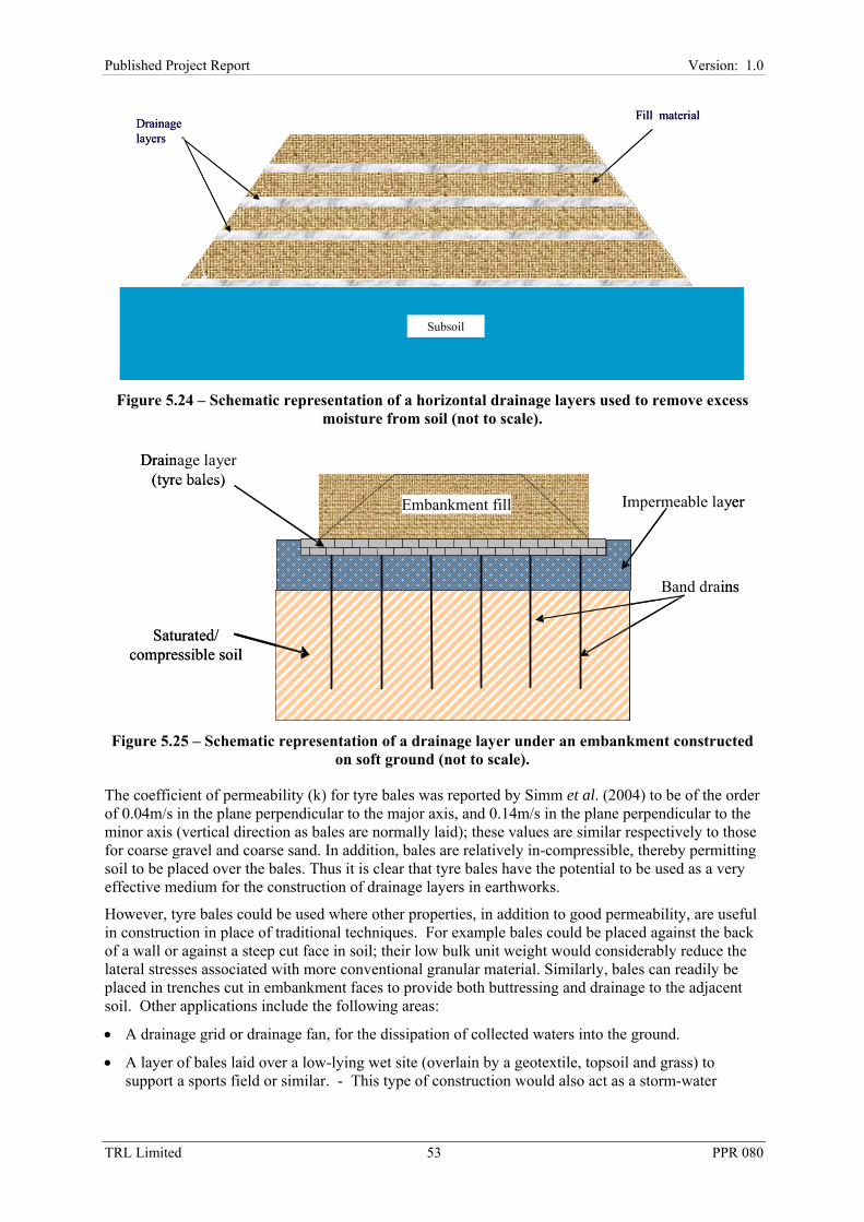
53TRL Limited 53 PPR 080
Published Project Report Version: 1.0
Figure 5.24 – Schematic representation of a horizontal drainage layers used to remove excess moisture from soil (not to scale).
Figure 5.25 – Schematic representation of a drainage layer under an embankment constructed on soft ground (not to scale).
The coefficient of permeability (k) for tyre bales was reported by Simm et al. (2004) to be of the order of 0.04m/s in the plane perpendicular to the major axis, and 0.14m/s in the plane perpendicular to the minor axis (vertical direction as bales are normally laid); these values are similar respectively to those for coarse gravel and coarse sand. In addition, bales are relatively in-compressible, thereby permitting soil to be placed over the bales. Thus it is clear that tyre bales have the potential to be used as a very effective medium for the construction of drainage layers in earthworks.
However, tyre bales could be used where other properties, in addition to good permeability, are useful in construction in place of traditional techniques. For example bales could be placed against the back of a wall or against a steep cut face in soil; their low bulk unit weight would considerably reduce the lateral stresses associated with more conventional granular material. Similarly, bales can readily be placed in trenches cut in embankment faces to provide both buttressing and drainage to the adjacent soil. Other applications include the following areas:
• A drainage grid or drainage fan, for the dissipation of collected waters into the ground.
• A layer of bales laid over a low-lying wet site (overlain by a geotextile, topsoil and grass) to support a sports field or similar. - This type of construction would also act as a storm-water
Saturated/ compressible soil
Drainage layer (tyre bales)
Embankment fill Impermeable layer
Band drains
Saturated/ compressible soil
Drainage layer (tyre bales)
Embankment fill Impermeable layer
Band drains
Fill material
Subsoil
Drainage layers
Fill material
Subsoil
Drainage layers

54TRL Limited 54 PPR 080
Published Project Report Version: 1.0
reservoir that would assist reducing local flooding by storing water for slow release on infiltration (see Section 5.6, Soakaways).
• A water collection trap for run-off from a large impermeable surface– a trench encircling the site, lined with an impermeable membrane, backfilled with tyre bales.
• Use as anti-scour protection for river banks or bridge piers.
• As a trench drain for collecting run-off and transporting the discharge away.
It should be noted that tyre bales may be unsuited for situations where the water flow that contains large amounts of sediments or pollutants may become trapped in the voids within the bales under normal flow conditions. This could result in a potentially dangerous build up of contaminants that might be washed out at times of inundation. Silting up of the voids would also result in loss of permeability of the bales, leading to backing up of water and loss of function of the drain, potentially leading to instability of structures.
5.5.2 Design
In almost all instances a formal design for the capacity of drainage layers using tyre bales will not be required, as the flow rate of the moisture from the soil is very slow and the capacity of the bales will not be exceeded. However, for the case of providing drainage to a soil mass as depicted in Figure 5.26, the vertical separation of the layers should be selected to provide a drainage path of length that that will ensure consolidation of the soil within the design period. (Such calculations are beyond the scope of this report; however, acceptable results may be obtained from a consideration of one dimensional consolidation theory, as described in most text books on soil mechanics.)
Figure 5.26 - Schematic representation of a drainage layer (not to scale).
However, it is important to consider the potential for the migration of fine particles to be washed out, or the onset of piping. Where necessary such concerns should be obviated by encasing the bale layer(s) in a geosynthetic filter material; a wide range of products are commercially available and if required advice on usage/installation should be obtained from the manufacturer/supplier.
5.5.3 Construction
It is envisaged that the usage of tyre bales for drainage layers will be restricted to the drainage of earthworks until engineers become more familiar with this new and unique engineering product, and more knowledge is gained on their long-term performance. There can be little or no doubt that the future will see a greater use of tyre bales in a range of drainage applications.
Granular material
Geosynthetic
Fill material
Tyre bales
Fill material
Further layers
Further layers
Granular material
Geosynthetic
Fill material
Tyre bales
Fill material
Further layers
Further layers

55TRL Limited 55 PPR 080
Published Project Report Version: 1.0
The following is intended as an aide-memoire for the construction of an earthwork incorporating tyre bale drainage layers with a geosynthetic filter material around the bales to stop the migration of fine particles from the fill material.
1) What is the required purpose of the drainage system.
2) What is the required service life.
3) Are tyre bales suitable as a filter medium.
If tyre bales are suitable for use on the scheme, then the following points should be considered.
4) Determine number and dimension of the drainage layers and ensure that sufficient tyre bales will be available to complete the scheme.
5) Determine the vertical spacing between the drainage layers
6) Select a suitable geosynthetic filter material
7) Prepare the area for the drainage layer, ensuring that the plan area is slightly greater than that required for the tyre bales
8) Lay the geosynthetic over the area under the bales and ensure that sufficient provision is made for the geosynthetic to be wrapped completely around over the bales (and the overlying granular layer, see Step 3). Where several lengths of geosynthetic are required a minimum overlap of 500mm should be used between adjacent lengths
9) Lay the tyre bales
10) In-fill the gaps between adjacent bales with coarse gravel
11) Lay and level 300mm of coarse gravel over the tyre bales
12) Wrap and overlap the geosynthetic covering the tyre bales and gravel layer
13) Place and compact a layer of fill or surcharge material to the required depth (for optimum drainage conditions)
14) Place the next layer of geosynthetic directly on to the fill material
15) Repeat Steps 8 to 13 until the design height of the earthwork has been achieved.
A schematic diagram, showing one layer, is presented in Figure 5.26.
Throughout construction, care should be taken to maintain the correct profile of the earthwork. This should be ensured by normal surveying techniques. If the fill material is very soft it may only be possible to place one or two layers of fill, without incurring excessive deformations and endangering the lives of the site operatives. In such instances a staged construction process should be implemented.
5.5.4 Cost Implications
Depending on the local situation, tyre bales may offer a small or large (or sometimes negative) financial advantage over conventional aggregate drainage layers. However, where large numbers of tyres require disposal, and baling is done locally, then their usage is likely to be cost-effective as a filter medium for drainage layers. This is especially likely during earthworks construction or reconstruction where a line or ‘fan’ of bales can be placed as fill material is placed.
5.5.5 Successful Applications
There are no known applications of tyre bale drainage layers as yet.

56TRL Limited 56 PPR 080
Published Project Report Version: 1.0
5.6 Storm Water Management Systems and Rainwater Soakaways
With increasing building development and expansion of infrastructure, more surfaces which were previously grass or soil are now hard surfaces. This leads to greater overall volumes and higher peak volumes of storm water to be accommodated by drainage systems and watercourses. To control the release of rainwater greater use is being made of water storage and flow attenuation systems. Impermeable surfaces such as pavements and roofs significantly increase surface water run-off to be dealt with by drainage systems and watercourses. Regulatory agencies are promoting the use of Sustainable Urban Drainage Systems (SUDS) that aim to reduce run-off to 20% of the total rainfall, a value typical of a greenfield site (see Planning Policy Guidance PPG 25 and CIRIA, 2001).
In addition to this, the building regulations dictate an order of priority for the selection of surface water management from buildings, these are:
1) An adequate soakaway or some other adequate filtration system, or where that is not reasonably practical.
2) A watercourse, or where that is not practicable.
3) An appropriate sewer.
A number of products are available that provide temporary subterranean storage for excess storm water. This water is then released slowly into water courses / sewers using some form of outflow-control device. Alternatively, the water is allowed to soak away into the soil underneath the units to recharge groundwater (rainwater soakaways).
Tyre bales have several properties which make them amenable for use in storm water storage attenuation systems and as rainwater soakaways. They have about 50% porosity, a suitable permeability, and reasonably good load bearing capacity. Importantly, tyre bales provide a much cheaper option than other commercially available products.
Small soakaways have traditionally been constructed using stone-filled holes or trenches. Table 5.1 gives a comparison of the various properties of tyre bales, typical commercially available products and stone fill for use in storm water attenuation systems and soakaways. Table 5.2 gives some advantages and disadvantages of the various products.
Table 5.1 - Comparison of some of the properties of materials used in water storage systems.
Storage system Typical unit dimensions
(m3)
Unit weight
(kN/m3)
Voids ratio
Effective porosity
Cost of storage unitsa (£/m3)
Purpose-built storage cell
2.4 × 1.2 × 0.5 or
1.0 × 0.5 × 0.2
< 0.1 19.00 0.95 70 – 300
Stone-filled excavation
Variable 15 0.33 – 0.67b 0.25 – 0.40b 12 – 60
Tyre bales 1.5 ×1.2 × 0.7 10 0.72 - 1.00 0.42 - 0.50 9 – 13.50c a Unit cost, excluding excavation, installation and all ancillary items. b Dependent on particle size and angularity. c Includes an allowance for the cost of the granular infill between adjacent bales, see Section 6.9. Note that the sum of the values given in this Table are approximations; further details are provided in Section 4.
5.6.1 Typical commercially available storage cells
These are basically open modular plastic units (rather similar to milk crates in appearance) with the void space (Vv) being a very high percentage of the volume of the unit (V); the ratio Vv:V is termed the porosity of the unit.

57TRL Limited 57 PPR 080
Published Project Report Version: 1.0
One system employs polypropylene modules (0.5 × 0.4 × 0.1m, with a porosity equal to 0.95) that can be assembled together to form a subterranean structure used for storm water storage or as a soakaway; the units can be clipped together in single layers and/or pegged together in multiple layers. Conventional pipework is connected to the units by means of a number of adaptors. An impermeable geomembrane wrap is required for storage solutions and a permeable geotextile wrap is used for soakaway solutions.
Table 5.2 - Some advantages and disadvantages of different storage systems.
Storage system
Advantages Disadvantages
Purpose-built storage cell
Lightweight, modular, easily handled and assembled
Large storage volume relative to the unit volume and the volume of excavated material.
All ancillary items readily available
Can have good load-bearing capacity
Designs available from manufacturer/supplier
Significantly more expensive than other options
Stone-filled excavation
Simple, widely used, tried and trusted system
Medium cost option. Cost may be reduced by utilising recycled/secondary aggregates
Poor % storage volume – more excavation & more spoil for disposal
Tyre bales Inexpensive
Useful function for otherwise ‘waste’ material
Reasonable % storage volume
Require more space than purpose-built cells (but less than stone-fill)
Another system again uses polypropylene units (1.0 × 2.0 × 0.48m) also with porosity equal to 0.95. The units consist of vertically aligned hexagonal tubes which have a large vertical load bearing capacity. Each unit has a non-woven polyester fabric covering on each end to prevent intrusion of fines into the voids.
Commercial units have the advantage of a very high porosity and have a range of pipes and accessories available to complete the works. The effective porosity of tyre bales has been determined by Simm et al. (2004) to range from 0.42 to 0.50. Thus a tyre bale ‘storage chamber’ would have to be about twice as large as that required by commercial storage units; however, tyre bales have a very significant cost advantage over commercial units though delivery to site may be more expensive due to the larger volume of bales needed. When using tyre bales, ancillary items such as pipes and silt traps need to be specifically designed rather than being available as a part of the commercial ‘package’ but the cost overall cost will normally be small in comparison with the cost savings achieved by using the bales.
5.6.2 Rainwater soakaways
Run-off is collected and fed into rainwater soakaways, where the water drains away (at a rate dependant upon the underlying soil permeability and groundwater level). The capacity of the soakaway should be designed for a specified storm return period and duration.
Existing design guidance for soakaways
Small soakaways (serving areas less than 25m2) are usually constructed using square or circular pits filled with rubble, or lined with dry jointed masonry or perforated concrete rings. A design rainfall of 10 mm in 5 minutes is quoted in the building regulation approved, document H, as being appropriate for the worst case. It is generally considered that domestic rubble-filled soakaways may need to be renewed about every ten years.
For soakaways serving areas larger than 25m2, reference should be made to the following documents:
• BS EN 752 Drain and sewer systems outside buildings (BSI, 1996; 1997a; 1997b; 1998).

58TRL Limited 58 PPR 080
Published Project Report Version: 1.0
• BRE (1991) Digest 365 – Soakaways.
• CIRIA (1996) Report 156: Infiltration Drainage.
Of the above documents, BRE (1991) is the most commonly used.
A soakaway must not be used:
• Within 5m of a building or road (see BS8301; BSI, 1985), 2.5 m of a boundary or in an area of unstable land.
• In ground where the water table reaches the bottom of the soakaway at any time of the year.
• Near any drainage field, drainage mound or other soakaway so that the overall soakage capacity of the ground is exceeded and the effectiveness of any drainage field impaired.
• Where the presence of contamination in the run-off could result in pollution of ground water source or resource.
A cautionary note must also be made regarding the use of soakaway drains of any type, whether constructed using tyre bales or other materials, in karst terrain, except in some juvenile types of karst. Waltham et al. (2005) state that design codes should ban soakaway drains, require the use of flexible lines and junctions on all water and drainage elements, and require the diversion of all inbound drainage flows.
The likelihood of contamination on a scale that would concern the environmental regulators is limited (see Section 4.9). However, the opportunity to monitor the outflow of a soakaway or storm water feature constructed from tyre bales would provide data that could only enhance the available knowledge of tyre bale performance. Designers should take due note of the limited potential for combustion of tyre bales as detailed in Section 4.10.
Long, narrow soakaways offer the best solutions as this maximises the surface-area through which water can pass out of the soakaway and into the soil. Variations on the basic straight trench given in BRE (1991) include E-shaped and ladder-shaped layouts. An efficient silt trap should always be included at the inlet to remove suspended solids to minimise loss of storage volume and the reduction of outflow permeability.
A design guide for soakaways using tyre bales
1. Determine the volume of water to be stored. Allowing for a little ‘permanently trapped’ water the bales have an effective porosity ranging between 0.42 to 0.50. For the purpose of design assume an effective porosity to the minimum value of the range. Thus for a required water storage volume (V) the required volume of bales to accommodate this volume of water is approximately 2.4V.
2. Assess the possible locations for the soakaway. Most clayey soils are essentially impermeable and thus soakaways are ineffective in these soils. The soakaway should be located above the natural ground water table to permit outflow of the stored water. Some soils are significantly weaker when wet and precautions may be required to avoid potential damage to foundations of buildings and roads: e.g., see advice in provided BS EN 8301. With certain soils, which are not moisture susceptible, it may be possible to site soakaways below minor roads and parking areas; competent geotechnical advice should be obtained for such situations.
3. Determine the inlet system and silt trap required plus any ancillary aspects – inspection access, maintenance access etc.
4. Excavate the opening to the required depth, ensuring that the plan area is slightly greater than that of the tyre bales.
5. Lay 100mm bed of coarse bedding, sand or non-angular granular material, level and compact.
6. Lay the geotextile over the base and up the sides of the trench. Where several lengths of geotextile are required a minimum overlap of 300mm should be used between adjacent lengths. One important aspect of the geotextile specification is the ‘apparent opening size’ of the pores of the

59TRL Limited 59 PPR 080
Published Project Report Version: 1.0
material. The apparent opening size of the geotextile should be specified to permit sufficient water flow but with sufficiently small pores to prevent clogging of the pores with detritus washed into the system. Advice is given in MCHW2 Clause 514 and elsewhere.
7. Lay the tyre bales, in-fill gaps between separate bales with coarse gravel.
8. Lay coarse gravel (~300 mm) layer over the tyre bales with a slotted inflow pipe(s) built into this layer as shown in Figure 5.27. Alternatively, if this gravel layer is not essential to help spread live loads other inflow designs may be considered. A gap can be left between bales, subsequently partly filled with coarse gravel and the inflow pipe installed with its crown level with the top face of the bales. A ‘fan’ of small diameter slotted pipes can form an inlet manifold on top of the bales taking up a minimum of available room.
Figure 5.27 – Schematic representation of a soakaway using tyre bales (not to scale).
9. A gully pot and silt-trap should be installed at the inlet to the system to minimise fine material entering the system reducing storage and tending to clog the geotextile.
10. Wrap and overlap the geotextile covering the tyre bales, gravel, and inflow pipe(s).
11. Lay 100mm coarse sand or non-angular granular material between trench walls and the soakaway structure and compact.
12. Lay 100mm coarse sand or non-angular granular material over the geotextile structure and compact.
13. For non-trafficked areas backfill with ‘as-dug’ material and topsoil as necessary.
14. Where competent advice has been received that permits some trafficking or parking, a layer of Type 1 or Type 2 sub-base (MCHW 1) should be placed and compacted. Until more detailed advice is available a minimum compacted depth of 150mm should be employed followed by the required pavement layers
15. Rainwater from roof areas may drain straight into the soakaway (although a small catch pit will intercept dust and detritus washed off the roof). For car parks and trafficked areas the water should enter through a catch pit and a petrol interceptor.
Silt trapInlet pipe Geotextile Coarse gravelDrain
Sand Tyre bales
Silt trapInlet pipe Geotextile Coarse gravelDrain
Sand Tyre bales

60TRL Limited 60 PPR 080
Published Project Report Version: 1.0
Guidance on design capacity
Various methods are available for assessing the ‘design volume’ of the soakaway. One commonly used method is the Wallingford Procedure (HR Wallingford, 1983) which assesses the total rainfall level of storms over defined time periods, ranging from 5 minutes to 48 hours in duration. The most critical condition is likely to be an intense summer storm especially where this follows a wet antecedent period such that the soakaway is still partly filled. A long, wet winter period can sometimes prove problematic with low evaporation and plant transpiration adding to the problems of a raised groundwater table.
Structural considerations
The depth of installation controls the dead load on the units (i.e., weight of backfill vertically downwards and the lateral earth pressure). Should live traffic loads be present these are likely to be more critical. The greater the thickness of the foundation and pavement layers the more dispersed the live loads will be. Soakaways are typically installed at shallow depths to maximise their hydraulic performance. The current recommendation is for the bales to be covered with about 300mm of coarse gravel as a load-spreading and ‘inflow layer’ plus about 150mm of sub base with its better load-spreading characteristics. When further information on the load bearing capacity of tyre bales and groups of bales is available more advice and more refined designs will be possible.
5.6.3 Storm water retention systems
A storm water flow attenuation system reduces peak flows from a storm event by storing it and releasing it more slowly to the sewer or receiving watercourse. This increases the available hydraulic capacity of the main sewage system, enabling it to absorb more run-off from adjacent areas. In the attenuation system the storm water run-off is directed into a (usually) subterranean storage system which then releases the water through an outlet pipe at a constant, fairly low flow rate. The low flow rates (regardless of hydraulic head) are achieved by using some kind of flow control device (e.g., orifice plate, vortex-control or ‘small pipes’). One general advantage of this type of system is that fairly large storage may be obtained with a fairly small loss of head (difference between inlet and outlet pipes) as long as a reasonably large plan area is available. Tyre bales can be employed to provide the storage capacity required (see Figure 5.28).
Figure 5.28 – Schematic representation of a storage/attenuation system using tyre bales (not to scale).
Sand base
Silt trapInlet pipe
Tyre bales
Outlet pipe
Impermeable geomembraneGeotextile
Coarse gravel
Flow control
deviceDrain
Sand base
Silt trapInlet pipe
Tyre bales
Outlet pipe
Impermeable geomembraneGeotextile
Coarse gravel
Flow control
deviceDrain

61TRL Limited 61 PPR 080
Published Project Report Version: 1.0
Design guide for storm water attenuation systems using tyre bales
1. Determine the volume of water to be stored. Allowing for a little ‘permanently trapped’ water the bales have an effective porosity in the range 0.42 to 0.50 For the purpose of design, assume an effective porosity equal to the minimum value of the range. Thus for a required water storage volume (V) the required volume of bales to accommodate this volume of water is approximately 2.4V.
2. Assess the possible locations for the storage system. Essentially the bales form a ‘water-tight’ storage chamber and thus potential softening of the soil and concerns about ground water table level are less significant than with soakaways. Despite this, disturbance of the ground and possible leakage from the chamber could lead to wetting-up and softening of some soils, so care should be taken during construction to minimise this possibility. Ideally, the storage chamber should be located under non-loaded or lightly loaded areas because of the relatively low stiffness of the bales (compared with many natural soils). Where significant imposed loads are anticipated competent engineering advice should be obtained.
3. Determine the inlet system, outlet system, silt trap required plus any ancillary aspects – flow control device, inspection access, maintenance access etc.
4. Excavate the opening to the required depth, ensuring that the plan area is slightly greater than that of the tyre bales.
5. Lay a 100mm bed of coarse bedding sand or non-angular granular material, level and compact.
6. Lay a thick geotextile over the base and up the sides of the trench to protect the impermeable geomembrane from damage. Alternatively, a sand layer may be used or a puncture-resistant geomembrane employed.
7. Lay the impermeable geomembrane on top of the geotextile over the base and up the sides of the trench.
8. Where joints are required overlap them or seal them in accordance with the manufacturers recommendations. Although some minor leakage might not be critical, in some circumstances an initially small leak could cause washout and piping leading to increasingly large flow.
9. If necessary protect the top of the geomembrane from damage, then lay coarse gravel to a sufficient depth to allow the laying of a slotted outflow pipe(s). Alternatively the pipes may be laid on thin (25 to 50mm) sand bedding with bales placed either side of the pipe to minimise the volume gravel required. In some soils it may be necessary to ensure a good seal between the pipe and geotextile to prevent the washout problem described above.
10. Lay the tyre bales, in-fill gaps between separate bales with coarse gravel.
11. Lay coarse gravel (~300 mm) layer over the tyre bales with a slotted inflow pipe(s) built into this layer. Alternatively, if this gravel layer is not essential to help spread live loads other inflow designs may be considered. A gap can be left between bales, subsequently partly filled with coarse gravel and the inflow pipe installed with its crown level with the top face of the bales. A ‘fan’ of small diameter slotted pipes can form an inlet manifold on top of the bales taking up a minimum of available room.
12. During storms large volumes of water will be entering the sealed storage chamber quickly. Air-locks could cause problems, reducing or preventing efficient in-flow so an air vent should be installed. This could be formed from a vertical pipe from a convenient point on the top of the chamber to the surface. Some form of cowl and/or protective box would reduce the likelihood of blockage of the vent.
13. A silt-trap should be installed at the inlet to the system to prevent fines entering the system and causing clogging.
14. Wrap and overlap the geomembrane covering the tyre bales, gravel, and inflow pipe(s).
15. Wrap and overlap the geotextile covering the geomembrane.

62TRL Limited 62 PPR 080
Published Project Report Version: 1.0
16. Lay 100mm coarse sand or non-angular granular material between trench walls and the soakaway structure and compact.
17. Lay 100mm coarse sand or non-angular granular material over the geotextile structure and compact. Back fill with ‘as-dug’ material and topsoil if necessary.
18. Where competent advice has approved some trafficking or parking, a layer of Type 1 or Type 2 sub-base (MCHW 1) should be laid and compacted. Until more detailed advice is available a minimum compacted depth of 150mm should be employed followed by the required pavement layers.
19. Rainwater from roof areas should drain into the storage system via a gully pot or silt trap to intercept dust and detritus; for car parks and trafficked areas the water should also be directed through a petrol interceptor.
The guidance on design capacity and structural considerations provided herein is similar to that given in Section 5.6.2 for rainwater soakaways.
5.6.4 Financial aspects of using tyre bales for water storage
While it is not possible to make a rigorous cost comparison between the usage of commercial storage units and tyre bales, simple comparisons may be made: e.g., consider a required a storage capacity of 100m3 and a cost of construction equal to £43/m3.
• Tyre bale system: The nominal volume of the excavation to contain the reservoir would be 240m3. Therefore, from Table 5.1, the cost of the tyre bales (and fill between adjacent bales) would be between £2,160 and £3,240, the cost of construction is estimated at £10,320, making a total sum of between £12,480 and £13,560.
• Preformed modular units: The nominal volume of the excavation to contain reservoir would be 105m3. Therefore, from Table 5.1, the cost of the units would be in between £7,350 and £31,500; construction costs are estimated to be £4,300. Thus the total cost would be in the range £11,650 to £35,800.
Thus it is probable that the tyre bales would provide cost savings for the construction of the soakaway.
Other factors however, require to be considered when selecting a solution to a scheme the end use of the area above the reservoir needs to be considered. These are summarised as follows:
i) Whereas modular units are able to withstand reasonable vertical stress (car parks and minor roads have been constructed over reservoirs of this type), tyre bales may deform and result in the surface cracking of a paved area.
ii) A further factor to be considered when costing a scheme is the logistics for the supply of the construction materials. Modular units are light yet bulky, and may easily be transported around the country. Tyre bales may be directly delivered to site, or a baler with a copious supply of tyres might be brought to the site.
iii) Modular units require less excavation than tyre bales and are therefore better suited to sites where the allowable area for construction area is limited.
iv) The speed of construction is likely to be faster with modular units than the tyre bales, due the simplicity of placement, and the need to infill the inter-bale voids.
In summary, a realistic cost comparison may only be undertaken when the details for the scheme are known, as so many factors are involved. Nevertheless it is probable that tyre bales are likely to provide a fully satisfactory and more economic construction solution in non-urban locations (excepting beneath road pavements) than modular storage cells. In small urban locations the disadvantage of the increased cost of the storage cells may be outweighed by other factors.

63TRL Limited 63 PPR 080
Published Project Report Version: 1.0
5.6.5 Successful Applications
Only one successful application involving a soakaway constructed using tyre bales is known at present. This was constructed in the Highlands of Scotland during the Summer of 2005. Figures 5.29 and 5.30 illustrate the construction process.
Figure 5.29 – Tyre bale soakaway construction, Highland, Summer 2005.
Figure 5.30 – Tyre bale soakaway construction, Highland, Summer 2005.
Several further tyre bale soakaway construction projects are known to be at various stages of the planning process on the Highlands of Scotland as of the end of 2005.

64TRL Limited 64 PPR 080
Published Project Report Version: 1.0
5.7 Environmental Barriers
Environmental barriers are being considered (and constructed) with increasing frequency, in both suburban and rural locations as communities require an improved standard of life free from unwanted intrusion. The barriers serve two main functions: first the reduction of visual intrusion and second the reduction in noise to the protected area. The following advice is written primarily in relation to intrusion by road traffic noise, but is equally applicable for factories, busy railway lines, building sites etc.
Those un-familiar with the concept, make-up and usage of environmental noise barriers (including factors that affect their performance) are recommended to refer to a succinct booklet Keeping the noise down (FHWA, undated) which provides an overview of these and other factors.
The majority of published information on the design and construction of environmental noise barriers relates to proprietary systems, much information being available from the Internet. In the United Kingdom the primary documents relating to the construction of environmental barriers adjacent to highway network are:
• HA 65/94 Design Guide for Environmental Barriers (DMRB). The Advice Note (AN) provides guidance for the design of environmental barriers. The AN provides a comprehensive overview of all aspects and types of environmental barriers. Much emphasis is placed on aesthetics, ensuring that the barrier fits in with the character and ambience of its location. A clear distinction is made between the requirements for urban and rural locations. A range of case studies are provided, with a descriptive analysis on the selection of the barrier, siting, height, construction materials etc.
• HA 66/95 Environmental Barriers- Technical requirements (DMRB). The AN is a companion to HA 65 and gives guidance on acoustic performance, forms of construction and physical properties of materials.
• Clause 2504 Environmental Barriers, Specification for Highway Works (MCHW 1) and the associated Notes for Guidance (MCHW 2). The Clause stipulates the HA’s requirements for the construction and performance. The specified construction materials are brickwork, timber and/or concrete. Other materials may be used but must comply with the requirements of Appendix 25/4 of the SHW.
The construction of environmental barriers remote from the highway are obviously not bound by the requirements of the HA. In such situations a potential the developer may find Guidelines on Design of Noise Barriers (Hong Kong Government, 2003) to be a useful document. Though the document is smaller than the above HA documents, it is comprehensive and includes chapters on design considerations, aesthetics, maintenance, a checklist for construction and operation, and a bibliography and references.
A wide variety of materials and proprietary systems are available for the construction of environmental barriers, many of these incorporate living vegetation which is aesthetically pleasing. Tyre bales may be used to construct barriers; examples of how this can be successfully achieved are described in the following sections.
5.7.1 Environmental barrier design: considerations for design and construction
In general, the construction of an environmental barrier is not a complex procedure. But by their very nature environmental barriers are highly visible and attract a lot of public comment; therefore the selection of the optimum location, appearance and materials for construction, should be made with consideration and care. This latter is not always straightforward and the following list (after HA 65/94) attempts to set out a procedure that may be adopted for generating a preferred solution for a barrier scheme.
• Consider initial alignment options.
• Identify affected communities and areas.

65TRL Limited 65 PPR 080
Published Project Report Version: 1.0
• Review alignment options.
• Identify noise reduction and visual screening objectives for each location.
• Assess the landscape or townscape character.
• Design options to suit the local context and alignment.
• Compare the effectiveness of alternative solutions.
• Assess the visual impact of alternative solutions.
• Consider the advantages/disadvantages for each design.
• Refine preferred option.
• Carry out final assessment.
5.7.2 Construction with tyre bales
Tyre bales provide a simple means of constructing an environmental barrier. The bales can be laid in a variety of patterns and guidance on this aspect of design and construction is given in Section 6.3. The simplest arrangement has a brick-like appearance (in longitudinal section) and results in a pyramidal shape with the base width of the tyre bales about twice the height of the barrier as depicted in Figure 5.31; arrangements with steeper side slopes are not recommended.
Figure 5.31 - Schematic representation of an environmental barrier constructed from tyre bales, with a ‘green’ vegetative cover on one side and a reinforced soil slope on the other (not to scale). Fill limiting the vertical height of tyre bales to 3m, see Section 6.5, has been omitted to clarity.
Tyre bales are not attractive to look at and require some form of covering: in addition tyre bales should be protected from degradation by ultra-violet light. However, protection and an aesthetically pleasing ‘green’ appearance, may be readily achieved. For example, soil grow-bags or top soil may be placed on the terraces and against the vertical faces of the steps formed by the bales, followed by the planting of rapid growing dense foliage such as ivy. It is strongly advised that a blanket of natural or synthetic non-woven material should be laid directly on to the horizontal and vertical surfaces of the bales to minimise the loss in fines from the topsoil; the blanket will act as a root-matting and will assist the retention of moisture.
In urban areas a formal façade might be more fitting with the local ambience. This could take the form of lightweight panels fastened to formwork that had previously been attached to the bales. The panels could be made of a thermoset plastic, which is easy to colour and form and has a high stiffness. Other materials might also be used: e.g., foamed concrete which has a similar density to the tyre bales and may be moulded to give the appearance of natural rock.
Populated or quiet zone
Subsoil
Reinforced soil slope
Ground level
Source of noise or visual intrusion
Tyre bales
Tyre bales with a soil and vegetative covering
Populated or quiet zone
Subsoil
Reinforced soil slope
Ground level
Source of noise or visual intrusion
Tyre bales
Tyre bales with a soil and vegetative covering

66TRL Limited 66 PPR 080
Published Project Report Version: 1.0
The design of a façade (and the necessary formwork) are beyond the scope of this report, but suffice to note that for any impermeable façade provision must be made for the ingress and egress from the structure.
A further method of protecting the bales is to construct a steepened slope against the face of the barrier incorporating soil reinforcement and compacted fill; the slope may be seeded with grass, or scrub vegetation. As before a geosynthetic mat should be positioned directly on the bales to prevent the loss of soil particles. These two examples for protecting the barrier are shown schematically in Figure 5.31.
A steepened slope may loosely be defined as one that is steeper than the natural angle of repose of the soil from which it is constructed, and thus requires some artificial method of stabilisation such as soil reinforcement. For the barrier described above, the soil reinforcement might typically be a geosynthetic mesh, laid horizontally within the soil, and anchored by laying/placing a short length or ‘tail’ between successive layers of bales; the other end may simply terminate at the surface or be wrapped around the soil layer as shown in the Figure 5.31. As construction details will necessarily be different for individual schemes, users are recommended to contact a geosynthetic supplier/manufacturer for advice before commencing such works.
In situations where space is not a limiting issue a barrier can be constructed with a core of tyre bales, protected with shallow side slopes. Soil may be placed and compacted against both the sides or landscaped to fit with some pre-determined scheme, as depicted in Figure 5.32; such an arrangement does not require stabilisation of the slopes. A non-woven geosynthetic should be laid directly onto the bales before placement of the soil, to stop fine particles being washed into the tyre bale matrix, and in instances of high rainfall, would obviate the onset of piping that might lead to deformation of the soil slope. There is no reason why, if the soil cover is thick enough that trees should not be planted on these artificial slopes. This same technique could be used to construct artificial landscaped slopes at any location.
Figure 5.32 - Schematic representation of a landscaped embankment with a tyre bale core (not to scale). Fill limiting the vertical height of tyre bales to 3m, see Section 6.5, has been omitted to
clarity.
If the available space is severely limited a tyre bale barrier may be inappropriate and an environmental fence of wood, concrete or other material may be the only practical option. Hybrid constructions may be developed using a small tyre bale bund (covered with soil and vegetation) topped with an anti-noise fence, to increase the effective height and therefore the shielding effect while providing an attractive appearance in a restricted location. The foundation for the fence must receive serious consideration at the design stage, as it is un-likely that the tyre bale bund would be sufficiently stable to support the live loading attracted by the fence due to wind loading and passing traffic. It is likely that the fence foundation may need to be within ground beneath the bund.
5.7.3 Embankments on soft ground
Tyre bales have a bulk unit weight of about 60% of that of soil. Thus bales might be used as lightweight fill for any embankment constructed on soft ground (as depicted in Figure 5.17). Should
Placed and compacted soilTyre bales
Subsoil
Placed and compacted soilTyre bales
Subsoil

67TRL Limited 67 PPR 080
Published Project Report Version: 1.0
the embankment be intended to support a road or highway reinforcements may be required to ensure the coherence of the artificial fill; to date this technique has not been used in the United Kingdom but there are no insurmountable reasons for this to remain the case. The construction of embankments on soft ground is described in Section 5.3.
5.7.4 Vegetation on tyre bale barriers
It is difficult to envisage a tyre bale barrier being used without some attempt being made to disguise its appearance. Soil placed directly on the tyre bales would soon be eroded away unless, as previously described, soil bags and a geosynthetic mat are used to restrict loss of fine soil particles. A regular and regulated water supply must be provided to support the early stages of growth, though the flow rate may be reduced as the vegetation becomes established. The rate of supply will vary dependent on the type of vegetation, time of year and the location within the UK. The provision of water is critical to the success of the project, and the importance of this cannot be overstressed; it is recommended that expert advice is sought.
Experience has shown that one of the hardiest vegetative growths is ivy, which has the benefit of rapid coverage and a need for minimal quantities of water when fully established. In the West Country, Wales and the North of England, when the ivy has become fully established, natural precipitation may be sufficient to sustain life but elsewhere in the country a limited provision of water may be required for the life of the structure. However, wherever possible the growth of wild flowers should be encouraged. This point was recognised many years ago and led to the publication of The Wildflower Handbook (HA 67/93: DMRB 10.3.1). (Note that this Advice Note is contained within Section 3 of Volume 10 of the DMRB and not in Section 4 as stated elsewhere by other HA documents.) The appearance of these bunds will be similar to a ‘Devon Bank’ or a ‘Cornish Hedge’. In a traditional Devon Bank, deeply cut turves, possibly containing native wild flowers are built up in a wall. With the comparatively high rainfall in the West Country vegetation can be viable on banks up to 1.7m high without artificial irrigation. A Cornish Hedge is an earth mound with its steep faces maintained by building natural stone slabs into them. Subsequent to construction, native plants can colonise the top and sides of the ‘hedge’.
Establishing vegetation on a slope 1:2.5 or less, is relatively simple, but care is required to provide the optimum growing conditions. A dedicated water supply is advised and expert advice should be sought when selecting the vegetation and growing medium.
5.7.5 Fire hazard
A perceived disadvantage of environmental barriers constructed from tyre bales, is the potential to constitute a fire hazard. Tyres do not easily catch light, and a sustained period of high temperatures is required before ignition occurs (see Section 4.10). Such situations are unlikely to occur as a result of a road traffic accident. However a sensible precaution would be to ensure that tyre bales are covered with soil (see Section 6.6). In some locations an intervening safety fence may be required if the tyre bale barrier is close to the road.
5.7.6 Successful Applications
There are no known applications of tyre bale environmental as yet.

68TRL Limited 68 PPR 080
Published Project Report Version: 1.0
6 Construction Issues
6.1 Supply and Production of Tyre Bales
The availability, cost, transportation, storage and handling of bales will all need to be considered prior to making a decision to use these materials in construction.
It is particularly important before embarking on any project that a verification check is performed to ensure that adequate tyres are available to manufacture the tyre bales required for a given project. Figure 6.1 gives an indication of both the number of bales required to fill a given volume and, indeed, the number of tyres likely to be utilised in their manufacture. Maxima and minima are given based upon the variation in tyre bale sizes (see Section 4.1) for the number of bales required and on the number of tyres in each bale (see Appendix B.2 for the number of tyres required.
Figure 6.1 – Number of bales required to fill a given volume and tyres required in their manufacture. Maximum and minimum values are given to allow for variations in bale
dimensions and thus volume.
The issue of planning is taken a step further in Figure 6.2, in which the number of 8 hour (two man) shifts required to manufacture tyre bales of a given volume is represented. The calculations undertaken to develop the data presented were based upon a production rate of 4 bales per hour as advised by Northern Tyre Recycling.
Together Figures 6.1 and 6.2 should enable a rapid assessment of the approximate level of material, plant and labour resources required to generate the tyre bales required for a given project. In particular the evaluation of the number of tyres can give a rapid indication of whether local resources are sufficient. This should help in the selection of projects in areas of adequate tyre resources and therefore aid local authorities, for example, in adhering to the proximity principle which essentially dictates that waste materials should be reused, recycled or disposed as close as possible to their point of arising.
0
250
500
750
1,000
1,250
1,500
0
Num
ber
of B
ales
500 1,000 1,500 2,000
Volume Required (m3)
0
50,000
100,000
150,000
200,000
Number of Tyre Bales Required
Number of Tyres Required
Num
ber
of T
yres
0
250
500
750
1,000
1,250
1,500
0
Num
ber
of B
ales
500 1,000 1,500 2,000
Volume Required (m3)
0
50,000
100,000
150,000
200,000
Number of Tyre Bales Required
Number of Tyres Required
Num
ber
of T
yres

69TRL Limited 69 PPR 080
Published Project Report Version: 1.0
Figure 6.2 – Number of 8 hour (two man) shifts required to manufacture tyre bales to fill a given volume. Maximum and minimum values are given to allow for variations in bale
dimensions and thus volume.
6.2 Handling of Tyre Bales
Tyre bale handling must incur the minimum risk of damage to the steel tie-wires (see also Winter et al., 2005a). The completed bales are robust enough to endure normal handling but should never be lifted by the galvanised steel tie-wires. This can cause the wires to break and the bale break up.
Approaches that have been tried include webbing straps wrapped around the bale and lifting ropes formed as part of the bale (see Appendix B) to allow a simple back-actor to lift the bales. However, the most successful was the use of a ‘loggers’-clam’ (Figures 6.3 and 6.4). A loggers’ clam is a hydraulically operated grab which can be attached to a variety of hydraulic equipment and provides an appropriate lift-and-place methodology while allowing the bale to be rotated to the correct alignment.
Figure 6.3 – Use of a ‘loggers’-clam’ to handle tyre bales.
0
10
20
30
40
50
500 1,000 1,500 2,000
Volume Required (m3)
Num
ber
of S
hift
s
0
10
20
30
40
50
500 1,000 1,500 2,000
Volume Required (m3)
Num
ber
of S
hift
s

70TRL Limited 70 PPR 080
Published Project Report Version: 1.0
Figure 6.4 – Use of a ‘loggers’-clam’ to handle tyre bales.
6.3 Alignment and Layout
6.3.1 Alignment
The manufacturing process renders tyre bales inherently non-homogeneous. Information on the relative stiffness in each of the three dimensions is not currently available (see also Winter et al., 2005a).
The Z-X plane (Figure 6.5) is likely to have a high stiffness and should be installed such that it attracts the maximum load, horizontal for a road. The X-Y plane is perpendicular to the loads applied during manufacture of the tyre bales and it is recommended that it is aligned perpendicular to the maximum confinement in the structure (i.e., with the tie-wires in line with the direction of a road, for example).
Bursting of the galvanised tie-wires has not been known to occur spontaneously in practice. However, it has been suggested that once the tyre bales are in place then the tie-wires could be cut to allow the gaps between the bales to close up. Such an approach is untried and it must also be pointed out that doing so will alter the behaviour and properties of the bales (see Section 4), not least in the all important areas of frictional resistance and permeability. A preferred option is to fill the voids between the bales with dry sand or similar material (see Section 6.4).
6.3.2 Two-Dimensional Layout
There are three different options for the two-dimensional placement of tyre bales (i.e., in a single layer). These are illustrated in Figure 6.6. Each of the layouts has advantages and disadvantages (see also Winter et al., 2005a).
The chessboard layout (Figure 6.6a) is simple to construct and has been used successfully. It does not however provide mechanical interlock to resist differential lateral movement. Such resistance must come from friction and passive resistance between adjacent bales and the inter-bale fill material. However, the main threat to the integrity of a two-dimensional tyre bale layout is from differential vertical, rather than lateral, movement.

71TRL Limited 71 PPR 080
Published Project Report Version: 1.0
Figure 6.5 – General features and layout of a tyre bale.
Figure 6.6 – Plan view of possible two-dimensional tyre bale layouts: (a) chessboard; (b) stretcher bond; and (c) staggered.
The stretcher bond layout (Figure 6.6b) affords improved resistance to lateral movement induced, for example, by traffic travelling in the “Z” direction. However, it is important to note that not only does this arrangement use more tyre bales (around 10% in the example in Figure 6.6b) for a given required plan area but that the castellations will need to be filled with granular material in order to prevent the creation of a potentially dangerous staggered edge. The filled areas will have a different stiffness and resistance to erosion than the tyre bales and such an arrangement could lead to differential settlement leaving a dangerously uneven edge.
Many of the comments made above in relation to the stretcher bond layout are also applicable to the staggered layout (Figure 6.6c). Notwithstanding that there is no particular advantage of this layout in terms of the resistance to traffic-induced loads, for example. The use of additional tyre bales is
Required Z
DimensionZ
X
Required X Dimension XX
(a) (b) (c)
Required Z
DimensionZ
X
Required X Dimension XX
(a) (b) (c)
Galvanised steel tie-wires Not to Scale: All dimensions are nominal
60’’ (1.50m)
50’’ (1.27m)
30’’ (0.76m)
Z
X
Y

72TRL Limited 72 PPR 080
Published Project Report Version: 1.0
considerably less than for stretcher bond as is the additional need for granular fill for the castellations. However, the castellations are positioned at either end of the tyre bale length (rather than at the parallel edges). This leads to the necessity for traffic, for example, to pass over these areas of potential differential settlement.
The chessboard pattern (tie-wires in line with the confining load; shortest dimension vertical) is recommended. In general, the bales should be placed as close together as possible in order to minimise any potential deformation under load and also the amount of inter-bale fill needed.
6.3.3 Three-Dimensional Layout
In applications that require a three-dimensional layout then, to some extent, a degree of stagger will occur almost by default. Typical examples include slope repair, embankments and, to a lesser degree, retaining walls.
The amount of stagger will depend to a marked degree upon the required slope of the front face. Figure 6.7 illustrates a typical arrangement for a repair to a failure in a cutting slope; this is similar to the approach discussed in Section 5.2 and detailed further by Prikryl et al. (2005) and Winter et al. (2005b).
Figure 6.7 – A typical tyre bale repair to a failure in a cutting slope. The tyre bales are shown in grey and all other areas comprise fill.
As the construction of three-dimensional layouts of tyre bales generally implies a degree of stagger then it is entirely appropriate not to introduce a further complication by staggering individual layers – a chessboard pattern is thus recommended.
Figure 6.7 illustrates not only the stagger built into the arrangement of tyre bales by the slope but also a lateral stagger designed to increase the stability of the tyre bale mass.
6.4 Fill Around Bales
It is important that tyre bales are butted up close to one another during the installation process. Not only does this ensure that the friction between the bales is maximised but also that the amount of fill needed to block the voids between the bales is minimised.
The fill between the voids is important for two main reasons. First, it helps to maximise the friction between the bales by minimising the effect of the voids between the bales caused by the slight curvature at the edges and corners of the bales. Second, it minimises the potential for the surrounding soil to be washed into these same voids.
Guidance on the amount of material required to fill these voids is given in Section 4.2.
The material used to fill the voids must be a compromise in terms of its properties between being able to flow freely into the voids, exhibiting frictional strength and being able to drain freely. As such coarse sand and fine gravel have been found to be good materials for this use. Glass cullet of an appropriate grading has also often been suggested for this application but the authors are not aware of
Section (Prior to the Placement of Cover)
Elevation – Front (Prior to Placement of Cover)
High Friction Fill Layer Separates Layers of maximum 3m Thickness
Section (Prior to the Placement of Cover)
Elevation – Front (Prior to Placement of Cover)
High Friction Fill Layer Separates Layers of maximum 3m Thickness

73TRL Limited 73 PPR 080
Published Project Report Version: 1.0
any such use as yet. Indeed, a water bowser has on occasions been used to promote the free flow of the material into voids (Winter et al., 2005b).
Other than to control the maximum height of tyre bale fill (see Section 6.5 and Figure 6.7) it is important that the amount of fill placed between layers of vertically adjacent layers of tyre bales is minimised: this helps to maximise the frictional strength of the mass (and avoids creating a layer between the bales of potentially lower friction materials) and also of minimising the amount of such materials required.
The filling of the voids, as described above, is particularly important for structural application in which the friction and interlock between the bales must be optimised (usually maximised). However, the importance of this part of the construction process should not be underestimated for drainage applications. Ensuring that the voids are well-filled will also ensure that the potential for adjacent soil washing into the voids is minimised. If the voids between the bales are not filled then it is recommended that the entire bale structure is encapsulated within a geosynthetic of suitable form to prevent the ingress of the surrounding soil into the bale mass.
6.5 Maximum Height of Tyre Bale Fill
Humphrey (1997) recommended a maximum height of tyre shred in embankments and similar structures of 3m. This was based upon analysis of a number of apparently spontaneously combusted fires in shred materials in the USA. Although, it is clearly shown in Section 4.10 that the risk of such events in tyre bale masses is negligible, emerging practice with some infrastructure operators in the US is to adopt this maximum height for tyre bales also.
Although this may not be justified on the grounds of the need for increased fire resistance, it does have the significant engineering benefit of providing a regulating layer to take up any minor irregularities in the surface. In this way a more competent structure is created and the level placement of successive layers of tyre bales is eased.
Thus, if the tyre bale fill is required to be higher than 3m, then a 0.3m to 0.4m layer of high friction fill should be placed to separate distinct 3m lifts of tyre bales. The granular fill may also provide a passage for the conduction of any heat generated by the tyre bale mass, still further reducing the risk of combustion.
In practice this is likely to mean that three layers of tyres bales (assuming that the bales are placed such that the Y-dimension is vertical, see Figure 6.5) are placed followed by a layer of high friction fill and then more tyre bales. The maximum height of an unbroken tyre bale lift will be around 2.4m in this scenario. A typical arrangement for a slope failure repair is illustrated in Figure 6.7.
6.6 Cover Depth and Stability of Cover
The ingress of plant roots and associated opening of voids could provide a potential pathway for chemical spills and water to enter the tyre bale mass. It is recommended that a minimum cover depth of 1m of inert fill be placed over all tyre bale masses with the potential for plant growth and that the planting of deep rooted plants be avoided where possible. The cover material placed over the tyre bales may be cohesive in nature, as this will compact well around the bale core and will help to prevent the ingress of rain water: e.g., some of the materials defined as General Fill Class 2, Table 6/1 SHW (MCHW 1).
The stability of the cover soil is an issue that needs to be addressed, especially in situations where the associated slope is steep and erosion can be a particular problem. Geosynthetic materials that contain growth media, often described as biosynthetics, can be particularly useful in this respect. The range of such materials is considerable and independent advice should be sought in terms of making such a selection.
Hessian mats in conjunction with seed mulch have been successfully used on slopes of up to 1:1.9 on the A650 Bingley Bypass in Yorkshire (Osborne, 2005), Figure 6.8. The successful use of such

74TRL Limited 74 PPR 080
Published Project Report Version: 1.0
materials on slopes much steeper than this may require the use of sacrificial staples to pin the Hessian mat to the topsoil.
Figure 6.8 – Slope successfully constructed at 1:1.9 on the A650 Bingley Bypass (from Osborne, 2005, with permission).
A promising solution for this type of requirement is a geogrid system based upon a 130mm diameter rope (Figures 6.9 and 6.10).
Figure 6.9 - Anti-erosion 'rope' geogrid for the promotion of vegetation growth on steep slopes developed by the Saxon Textile research Institute in Chemnitz, Germany (http://www.tu-chemnitz.de/tu/presse/artikel/forschung1.php?aid=114).
The rope can be manufactured from a range of biodegradable or non-biodegradable materials, fibres, chips or cuttings of natural or synthetic material, textile waste or even hay or straw. Much of the currently available information on this system is in German, with the exceptions of Anon (2005) and: http://www.treehugger.com/files/2005/08/erosion_stoppin.php
Initial field tests indicate the absence of any erosion over the winter months of the first year. While the idea as it stands appears attractive it is relatively untried and the costs of such a system are likely

75TRL Limited 75 PPR 080
Published Project Report Version: 1.0
to be in excess of those of a Hessian-based system as described above. Nonetheless, it certainly merits use in a trial situation.
Figure 6.10 - Anti-erosion 'rope' geogrid for the promotion of vegetation growth on steep slopes
developed by the Saxon Textile research Institute in Chemnitz, Germany (http://www.tu-chemnitz.de/tu/presse/artikel/forschung1.php?aid=114).
Such systems are unlikely to be effective for slopes in which the soil is placed at angles greater than the angle of repose. Where greater angles are required systems of steel mesh incorporating a seeded biosynthetic may be viable. These generally comprise a sheet of steel mesh designed to be lain horizontally. This is in turn attached to another sheet of steel mesh set at the desired slope angle to the first sheet. The pre-formed steel mesh elements are then placed with the tyre bales in order to form a smooth slope. The same material used to fill around the bales (see Section 6.4) may then be used to fill the void between the tyre bales and the steel mesh. Ideally a small amount (<10%) of organic matter would be placed in the material used to fill these voids. The use of Erosion Control Compost (ECC) has been suggested as being stable at slope of 1:2 or steeper (Texas Department of Transportation Specification Item 161). The opportunity to trial the specification item would be welcomed.
The angled sheet of steel mesh is usually covered with a biosysnthetic in order to promote vegetation growth. The vertical dimension of the steel mesh can be specified to match the dimensions of tyre bales making construction easier.
6.7 Drainage
It is known that wet conditions, where the water is stagnant, will encourage microbial activity and hence exothermic reaction. In contrast flowing water conditions, such as those following heavy rain or flooding, are more likely to cool the tyres.
Stagnant water may increase what is described in Section 4.10 as an otherwise negligible risk of spontaneous combustion in tyre bale structures. This serves to highlight the importance of following good engineering practice and ensuring good drainage. The provision of adequate drainage paths out of tyre bale structures should be a key feature of design.
The level of risk is not believed to be at a level at which it should preclude the use of tyre bales in drainage and stormwater applications as described in Section 5.6.
Tyre bales drain effectively (see Section 4.6) and the key criteria for effective drainage are ensuring that adequate falls are in place for water to drain away from the structure to a suitable location and that the boundaries between the tyre bale structure and the surrounding soil are suitably detailed. In

76TRL Limited 76 PPR 080
Published Project Report Version: 1.0
particular the boundaries should include granular drainage material and a geosynthetic separator/filter in order to ensure that water drains from the boundary and that the adjacent soil is not over-softened creating a potential weakness.
6.8 Contamination
The use of contaminated tyres and bale should be avoided from a viewpoint of pollution protection and any contaminated bales, particularly if the contamination is in the form of hydrocarbons, should be returned to the supplier.
6.9 Costs
The total cost for any given construction activity is generally determined by examining the elemental costs of materials, plant and labour. There is however a tendency to simply compare the unit costs of tyre bales to that of the materials that they are replacing, thus considering only one part of the potential savings. For example if tyre bales are viewed as a replacement for Type 1 Sub-Base (MCHW 1) priced at between £9 and £15 per tonne then assuming a density of 2Mg/m3 once compacted the cost is around £18/m3 to £30/m3. However the comparable cost for tyre bales at £12 to £15 per bale, based upon the volume quoted in Table 4.1, would be approximately £7.40/m3 to £9.20/m3. This does not take account of the material required to fill the voids which is around 0.28m3 per cubic metre bale. Thus, taking the price of Type 1 as the same as the void fill an additional £2.50 to £4.20 must be allowed per cubic metre. The cost of tyre bales is thus estimated at around £9/m3 to £13.50/m3, a favourable comparison with Type 1 Sub-Base.
While these figures may be valid for bulk applications, for low-volume road foundation applications they do not give a true picture. Tyre bales even when laid with their smallest axis vertical will have a depth of around 0.80m, approximately twice that of conventional road foundations. Thus the equivalent areal price of the aggregate construction is £7.20/m2 to £12/m2. This compares well with the equivalent areal cost of tyre bales at around £7.20/m2 to £10.80/m2. Clearly the two approaches are of similar materials cost but do not take account of either transport or labour costs.
The figures quoted are exclusive of transport for both materials. However, it is also true to say that prices for the transport of Type 1 may be somewhat less than for tyre bales due to the substantial network for the supply of such materials and the consequently lower transport costs. It is, however, likely that in most cases the difference in cost will not be fully offset by the difference in transport distance/cost.
In terms of plant and labour the construction process for tyre bales is very different to that for conventional materials. Conventional materials are usually compacted in-situ, consuming a great deal of labour and plant time. Tyre bales are simply placed and the voids filled and compacted. This is a much quicker process and while the cost savings are difficult to quantify on other than a project specific basis they are likely to be substantial.
Estimates for an embankment construction in Colorado (Zornberg et al., 2005) indicate that the cost of storing, protecting and handling tyre bales at site, including placement, is around $0.80/m3 (less than £0.50/m3). The estimates further suggest that the total cost of tyre bale fill was around half that of conventional imported fill and substantially less than the cost of most other lightweight materials such as expanded polystyrene, foamed concrete and shredded tyres. The only lightweight fill that compared even remotely favourably with tyre bales was pulverised fuel ash, but the density of pulverised fuel ash is such that its benefits in terms of being a lightweight fill are substantially less than those of tyre bales, dry density being typically measured in the range of 1.4Mg/m3 to 1.5Mg/m3 (Winter and Clarke, 2001; 2002).
The outline cost comparisons given above support the broad view that tyre bale fill is around half the cost of conventional fill. Even when lower cost fill is used, savings from simple forms of construction when using tyre bales compensate.

77TRL Limited 77 PPR 080
Published Project Report Version: 1.0
Other cost comparisons for tyre bales with conventional materials have also been found to be favourable, with Anon (1998; 2001) reporting substantial cost savings for the use of tyre bales in the foundations of roads over soft ground. However, the reported costs were strongly influenced by the savings made by the County Authorities in not paying for disposal and in the use of prison labour in the manufacture of the bales.
Cost outcomes for the B871 road construction over soft ground (see Section 5.1.9; Roadscanners, 2004; Winter et al., 2005b) highlighted the difficulty of making valid cost comparisons. Nevertheless construction costs were calculated as of the order of less than £245 per metre run of single track road. This compares with an estimated £100 per metre run for conventional construction on good ground. The difficulty in providing a truly valid cost comparison stems from the fact the conventional construction techniques were rejected on the basis that experience indicated that they would simply not be successful, and that other lightweight construction methods would not be economically viable. Thus if the tyre bales had not been available it is unlikely that the project would have gone ahead.
In terms of obtaining valid cost comparisons for tyre bales compared with conventional materials it is essential that all elements of cost (materials, plant and labour) are considered. Notwithstanding that the cost of tyre bale fill is approximately half that of conventional fill.
6.10 End of Service Life
The issue of what happens to tyre bales at the end of the service life of the structure of which they form a part is as important as for any other material. Clearly any disposal at a later date due to demolition for example will be determined by the prevailing legislation, regulation and interpretation at that time.
However, the appropriate management of such materials must seek to avoid disposal, either by their subsequent reuse in other structures or by incorporating them into any reconstruction. The latter is the most attractive option. In the example of a road construction that is to be refurbished the existing bales could be used as a construction platform for the reconstruction. Such an approach is most likely to succeed if the tyre bales are placed lower in the original carriageway so that they can form the foundation in the reconstruction. This process might be seen as broadly analogous with the reuse of existing piles by incorporation into new structures. This practice has become more prevalent in recent years as many urban centres lack sufficient space for new foundations.
As with all construction components the presence of tyre bales should be noted in the Health and Safety Maintenance File and any anticipated approaches to reincorporation and/or removal noted.
While information on the deterioration of tyres once buried in the ground is limited there is some evidence of tyres having been excavated from US landfills after 50 years in apparently good condition (Zornberg et al., 2004).

78TRL Limited 78 PPR 080
Published Project Report Version: 1.0
7 Summary and Recommendations Close to 40Mt tyres are scrapped in the UK each year. As the disposal of whole tyres to landfill is already banned and the disposal of shredded tyres to landfill will be banned during 2006 it is clear that solutions to the waste tyre problem are urgently required.
Energy recovery, or burning, of tyres can appear wasteful in resource terms and shredding is a process that requires a significant amount of energy. While these and other technologies will have a place in managing waste tyres, tyre baling is a process that shows considerable promise as a low energy, low cost means of forming a valuable construction product.
Waste Management Licensing has been a concern for some time as various Regulators have taken differing views as to whether tyres (and tyre bales) either constituted, or should be treated as, a waste. However, as of late-2005 both UK-mainland Regulators have taken the view that tyre baling and the subsequent use of such materials in construction is a low risk activity and that Waste Management Licenses will not be required for such activities.
Approximately 110 to 120 tyres are compressed in a bespoke baling machine and restrained with tie-wires. The process produces a rectilinear bale of approximate dimensions 1.30m by 1.53m by 0.82m, mass of around 890kg and a density of approximately 0.55Mg/m3. In addition to being considerably less dense than most conventional construction products, and therefore being highly suitable for construction over soft ground, the bales are highly permeable. These two features indicate that tyre bales are likely to play an increasing part in the future of construction works. In addition the baling process is a low energy option compared to other tyre recovery processes. During the tenure of this project tyre bales have been used in applications ranging from road foundations over soft ground, through slope failure remediation to soakaway construction amongst other diverse applications.
One of the main purposes of the project was to assist the tyre baling industry in achieving increases to the volume of tyre bales used in construction and, at the same time, to help raise the utility (or value) of those applications. This was to be achieved by preparing guidance on the design, construction and specification of tyre bales in construction. There are strong signs that this and other projects conducted in both the UK and the USA have contributed strongly to the emerging market for tyre bales for use in construction.
This report presents a series of guides which detail possible approaches to the design and construction of a wide range of applications: road foundations over soft ground; slope failure remediation; lightweight embankment fill; gravity retaining walls; drainage layers; storm water management systems; and rainwater soakaways, and environmental barriers. These applications were selected from more than 20 potential applications for tyre bales in construction in close consultation with the Project Advisory Group.
The application guides are supported by an extensive study of key properties and behaviours including dimensions, volume, mass, density, mechanical properties, hydraulic properties and behaviours in relation to durability, contamination potential, fire resistance, and human health and safety. Issues common to multiple applications are also presented, including the supply and manufacture of bales, their handling, alignment and layout, fill around the bales, maximum height of tyre bale fill, cover depth and cover stability, drainage, contamination, typical costs, and end of service life.
The manufacturing process of tyre bales is described in some detail and, with other information, used as the basis for an engineering specification.
Current needs for further research are clear. High quality mechanical tests should be a priority and include frictional response, stiffness and creep. Tests to date have been either fit-for-purpose or conducted on bales in the USA. The fit-for-purpose tests have generally been designed to suit a construction project-specific purpose and may be more or less transferable to more general uses. Tyres in the USA are generally larger than those used in Europe. Consequently tyre bales contain up to 17% fewer tyres. This will have an impact upon the internal structure of the bales and upon the

79TRL Limited 79 PPR 080
Published Project Report Version: 1.0
properties; the significance of this impact upon the measured properties of tyre bales is a relative unknown at present.
Pilot-scale or full-scale tests are also considered to be a priority. These may take the form of structures that are specifically constructed to be monitored in a controlled environment over the long-term or they may be intended for test to failure.
The production of a formal, non-product specific, specification which can be accepted by all quarters of the construction industry should also be a priority. This will need to be supported by detailed technical information.
Certainly the monitoring of tyre bale structures for deformation, leachate, temperature in the long-term and UV degradation over time would be a welcome opportunity to gather data of great value in confirming behaviours implied largely from desk study information.
The lack of data from such exercises should not preclude the further use of tyre bales in construction, nor should it prevent the development of tyre bale applications. The availability of data from such exercises should encourage and accelerate the take up of tyre bales and the development of the applications and market for tyre bales.

80TRL Limited 80 PPR 080
Published Project Report Version: 1.0
Acknowledgements The work described in this report was carried out in the Infrastructure Division of TRL Limited. The authors are grateful to Dr J M Reid who carried out the quality review and auditing of this report.
The authors are extremely grateful to the efforts of the Advisory Group. Without their input this project would not have been possible.
References This section includes references to texts referred to in the appendices to this report.
Anon (1998). Proposal to bale tires for use in road subgrade construction in two demonstration projects in Chautauqua County, New York. Falconer, NY: Chautauqua County Executive.
Anon (2000). Quality Control: the production of recycled aggregates. London: CRC Limited.
Anon (2001). Where the rubber really meets the road: Video. Falconer, NY: Chautauqua County Department of Public Facilities.
Anon (2004a). The quality protocol for the production of aggregates from inert waste. WRAP June. Banbury: Waste and Resources Action Programme. (Available at www.aggregain.org.uk.)
Anon (2004b). The quality protocol for the production of aggregates from inert waste in Scotland. WRAP September. Banbury: Waste and Resources Action Programme. (Available at www.aggregain.org.uk.)
Anon (2004c). Proposals for amendments to the Waste Management Licensing Regulations 1994 (as amended): a consultation paper. Department for Environment, Food and Rural Affairs; Welsh Assembly Government. London: DEFRA.
Anon (2005). Coarse new geogrid proves to be rough diamond. Ground Engineering, September, page 7.
Bassett, R H (1974). Proceedings of the foundation deformation prediction symposium, MIT. NHI Report Number FHWA-R-75-515, November. Washington DC: Federal Highways Administration.
Bassett, R H, K C Yeo and K C Brady (1989). The behaviour of a geogrid reinforced embankment at Stanstead Abbotts. TRL Contractor Report CR167. Crowthorne: TRL Limited.
BRE (1991). Soakaways. BRE Digest 365. Garston: Building Research Establishment.
BSI (1994). Code of practice for earth retaining structures, BS8002. London: British Standards Institution.
BSI (1995). Code of practice for strengthened/reinforced soils and other fills, B8006. London: British Standards Institution.
BSI (1996). Drain and sewer systems outside buildings, Part 1 - Generalities and definitions, BS EN 752. London: British Standards Institution.
BSI (1997a). Drain and sewer systems outside buildings, Part 2 - Performance requirements, BS EN 752. London: British Standards Institution.
BSI (1997b). Drain and sewer systems outside buildings, Part 3 - Planning, BS EN 752. London: British Standards Institution.
BSI (1998). Drain and sewer systems outside buildings, Part 4 - Hydraulic design and environmental considerations, BS EN 752. London: British Standards Institution.
BSI (1985). Code of practice for building practice. Withdrawn 1 March 2005. Superseded by BS EN 752: Parts 1, 2, 3 and 4. London: British Standards Institution.
CIRIA (1996). Infiltration drainage – manual of good practice. CIRIA Report R156. London: Construction Industry Research information and Advice (CIRIA).

81TRL Limited 81 PPR 080
Published Project Report Version: 1.0
CIRIA (1993). Design of flood storage reservoirs. CIRIA Report BO14. London: Construction Industry Research information and Advice (CIRIA).
CIRIA (2004). Roadwork: theory and practice, 5e. CIRIA Report X172. London: Construction Industry Research information and Advice (CIRIA).
CIRIA (2001). Sustainable urban drainage systems – best practice manual for England, Scotland, Wales and Northern Ireland. CIRIA Report C523. London: Construction Industry Research information and Advice (CIRIA).
Clayton, C R I, J Milititsky and R I Woods (1993). Earth pressure and earth-retaining structures, second edition. Guilford: Surrey University Press.
Clayton, CRI, N E Simons and M C Matthews (1982). Site investigation. London: Granada. (Second Edition available for download from http://www.geotechnique.info/.)
Collins, K C, A C Jensen and S Albert (1995). A review of waste tyre utilisation in the marine environment. Chemistry and Ecology, 10, 205-216.
Collins, K C, A C Jensen, J J Mallinson, V Roenelle and I P Smith (2002). Environmental impact assessment of a scrap tyre artificial reef. ICES Journal of Marine Science, 59, S243-S249.
Council Directive of 15 July 1975 on waste (75/442/EEC). Official Journal of the European Communities, No L 194/39, 25.7.75.
Council Directive of 18 March 1991 amending Directive 75/442/EEC on waste (91/156/EEC). Official Journal of the European Communities, No L 75/32, 26.3.91.
Coventry, S, C Woolveridge and S Hillier (1999). The reclaimed and recycled construction materials handbook. Publication C513. London: Construction Industry Research and Information Association.
Drews, E (2006). Personal communication to the first author.
Environment Agency (2005). Environment Agency Guidance on Low Risk Waste Activities. 5 September. http://www.environment-agency.gov.uk/commondata/acrobat/ea_guidance_sept05_1098102.pdf.
Environment Council (2003). The definition of waste as applied to tyres – Report 1: The current legal status. Seeking Solutions for Waste Tyres: Informing the Environment Agency’s Waste Tyres. Programme. London: The Environment Council.
Environment Council (2004). The definition of waste as applied to tyres – Report 2: Required exemptions to waste management licensing for tyre recovery. Seeking Solutions for Waste Tyres: Informing the Environment Agency’s Waste Tyres Programme. London: The Environment Council.
Escario, M V, L-A George, R A Cheney and K Yamamura (1997). Landslides: techniques for evaluating hazard. Report of PIARC Technical Committee on Earthworks, Drainage, Subgrade (C12), 12.04B. Paris: PIARC, World Road Association.
Fakher, A, M Khodaparast and C J F P Jones (2006). The use of mackintosh probe for site investigation in soft soils. Quarterly Journal of Engineering Geology and Hydrogeology, 39(2).
Farrar, D M (1971). A laboratory study of the use of wet fill in embankments. Laboratory Report LR406. Crowthorne: TRL Limited.
Farrar D M and K C Brady (2000). Drainage of earthwork slopes: a review. TRL Report 454. Crowthorne: TRL Limited.
Glover, T J (1997). Pocket Ref., Second Edition. Littleton, CO: Sequoia Publishing.
Gray, T (1997). Preliminary directional plan for CIWMN Market Development/Demonstrations Contract. Sacramento, CA: California Integrated Waste Management Board.
Haider, S I (Undated). Leachate from tires: review of studies on leachates from tires. Hutchins, TX: Entire Environmental Systems Inc.

82TRL Limited 82 PPR 080
Published Project Report Version: 1.0
Hird, A B, P J Griffiths and R A Smith (2001). Tyre waste and resource management: a mass balance approach. Viridis Report VR2. Crowthorne: TRL Limited.
HR Wallingford (1983). The Wallingford Procedure: Design and analysis of urban storm drainage. Volume 1: Principles, methods and practice. HR Wallingford, Wallingford.
Humphrey, D N (1996a). Engineering properties and water quality effects of tyre chips for landfill construction. Proceedings, Seminar on Landfill Design Using Tire Shreds. Arlington, TX: Texas Natural Resources Conservation Commission.
Humphrey, D N (1996b). Investigation of tyre shred exothermic reaction in tire shred fill located on SR100 in Ilwaco, Washington. Report Prepared for the Federal Highway Administration, March.
Humphrey, D N (1997). Summary of design guidelines to minimize internal heating of tire shred fills. Scrap Tire News, 11(8), August.
Hylands, K N and V Shulman (2003). Civil engineering applications of tyres. Viridis Report VR5. Crowthorne: TRL Limited.
Jayawickrama, P W, M S Hossain and T A Retterer (2000). Catalog of design details and charts. Research Study No 0-1876/Research Report 1876-P, Centre for Multidisciplinary Research in Transportation. Lubbock, TX: Texas Tech University.
John, N W M (1987). Geotextiles. London: Blackie.
Koerner, R M (1990). Designing with geosynthetics. New York: Prentice-Hall.
Lambe, T W and Whitman, R V (1979). Soil mechanics, SI Version. New York: John Wiley & Sons.
Liu, Y, J D Scott and D C Sego (1994). Long term behaviour of geogrids in reinforced clay slopes. Proceedings, Fifth International Conference on Geotextiles, Geomembreabes and Related Products, 3, 1181-1184. SEAC-IGS: Singapore.
McGown, A and H F Al-Mudhaf (1994). The effects of a hot dry climate on the strength of geotextiles and geogrids. Proceedings, Fifth International Conference on Geotextiles, Geomembranes and Related Products, 3, 1203-1208. SEAC-IGS: Singapore.
McLaren, D (1968). M6 trial embankment at Killington. Laboratory Report LR238. Crowthorne: TRL Limited.
Macgregor, F (2004). Personal communication to the first author.
Macrory, R (1998). High court rules on recycling. The Ends Report, November, Issue No. 286.
Macrory, R (2001). Cement kilns and waste. The Ends Report, April, Issue No. 315.
Macrory, R (2002a). European Court broadens meaning of waste recovery. The Ends Report, March, Issue No. 326.
Macrory, R (2002b). European Court rules again on the meaning of “waste”. The Ends Report, May, Issue No. 328.
Manual of Contract Documents for Highway Works. London: The Stationery Office. Volume 1: Specification for Highway Works (MCHW 1). Volume 2: Notes for guidance on the Specification for Highway Works (MCHW 2).
Nightingale, D E B and W P Green (1997). An unresolved riddle: tire chips, two roadbeds and spontaneous reactions. Testing Soil Mixed with Waste or Recycled Materials, ASTM STP 1275, April. American Society of Testing and Materials.
O'Reilly M P (1995). Highway embankments on weak compressible ground. TRL Project Report Number PR/CE/114/95. Crowthorne: TRL Limited. (Unpublished report available only on direct request to TRL Limited.)

83TRL Limited 83 PPR 080
Published Project Report Version: 1.0
Organisation for Economic Co-Operation and Development (1991). Ground engineering applications of geotextiles in road construction and maintenance. Report of the OECD Expert Group I8. Crowthorne: Transport Research Laboratory.
Osborne, M (2005). Geotechnical challenges of road construction in a tight corridor – the award winning Bingley Bypass. Lecture to the Scottish Geotechnical Group, Glasgow, 8 November.
Planning Policy Guidance (PPG) Note Number 25. Development and flood risk. Office of the Deputy Prime Minister (ODPM). The Stationary Office, London.
Prikryl, W, R Williammee and M G Winter (2005). Slope Failure Repair using Tyre Bales at Interstate Highway 30, Tarrant County, Texas, USA. Quarterly Journal of Engineering Geology and Hydrogeology, 38(3), 337-386.
Roadscanners (2003). The B871 tyre bale project – the use of recycled tyre bales in a lightweight road embankment over peat. Rovaniemi, Finland: Roadscanners.
Scottish Office (1994). Environmental protection act 1990: Part II, waste management licensing - The Framework Directive on Waste. Scottish Office Environment Department Circular 10/94. Edinburgh: Scottish Executive.
SEPA (2002). Waste data digest 2002. Stirling: Scottish Environment Protection Agency.
SEPA (2004). Paragraph 19 Waste for Construction and other ‘Relevant Works’. Available from: http://www.sepa.org.uk/pdf/regulation/waste/wmx_tg19_tech_guid.pdf Stirling: Scottish Environment Protection Agency.
Shulman, V L (2002). The status of post-consumer tyres in the European Union. Report VR3. Crowthorne: TRL Limited.
Simm, J D (2003). Sustainable re-use of tyres in port, coastal and river engineering – strategy for pilot projects. Unpublished Memorandum. Wallingford: HR Wallingford.
Simm, J D, M J Wallis and K Collins (2004). Sustainable re-use of tyres in port, coastal and river engineering: guidance for planning, implementation and maintenance. HRW Report EX 5070-2. Wallingford: HR Wallingford.
Smart, P and J G Herbertson, (1992). Drainage design. Glasgow: Blackie and Son Ltd.
Sonti, K, S Senadheera, P W Jayawickrama, P T Nash and D D Gransberg (2000). Evaluate the uses for scrap tires in transportation facilities. Research Study No 0-1808, Centre for Multidisciplinary Research in Transportation. Lubbock, TX: Texas Tech University.
Sprague, C J, R A Goodman and P J Kuck (1994). Durability assessment of exhumed polyester geotextiles. Proceedings, Fifth International Conference on Geotextiles, Geomembreabes and Related Products, 3, 1191-1194. SEAC-IGS: Singapore.
Todd, A J and G R A Watts (2004). Monitoring the performance of French drains with recycled shredded tyre topping. Unpublished Project Report UPR ISS/48/04 (3/323/R004). Crowthorne: Transport Research Laboratory. (Unpublished report available only on direct personal application to the author(s).)
Varnes, D J (1978). Slope movement types and processes. In: Special Report 176: Landslides: Analysis and Control (Eds: Schuster, R L and Krizek, R J). Transportation and Road Research Board, National Academy of Science, Washington DC, 11-33.
Waltham, T, F Bell and M Culshaw (2005). Sinkholes and subsidence: karst and cavernous rocks in engineering and construction. Chichester: Springer/Praxis.
Waste Management Licensing Regulations 1994. Environmental protection - the waste management licensing regulations 1994. Statutory Instruments 1994 No.1056. London: The Stationery Office.
Waste Management Licensing (England and Wales) (Amendments and Related Provisions) (No.3) Regulations. Statutory Instrument 2005 No. 1728. London: The Stationery Office.

84TRL Limited 84 PPR 080
Published Project Report Version: 1.0
The Waste Management Licensing Amendments (Scotland) Regulations 2003. Scottish Statutory Instrument 2005 No. 171. London: The Stationery Office.
The Waste Management Licensing Amendments (Scotland) Regulations 2004. Scottish Statutory Instrument 2005 No. 275. London: The Stationery Office.
Waste (Scotland) Regulations. Scottish Statutory Instrument 2005 No. 22. London: The Stationery Office.
Winter, M G (2002). A conceptual framework for the recycling of aggregates and other wastes. Proceedings of the Institution of Civil Engineers (Municipal Engineer), 151(3), 177-187.
Winter, M G (2005). Report on a Technical Visit to the United States of America: May 2004. The Delegate. London: Royal Academy of Engineering.
Winter, M G and B G Clarke (2001). Specification of pulverised-fuel ash for use as general fill. TRL Report TRL519. Crowthorne: TRL Limited.
Winter, M G and B G Clarke (2002). Improved use of pulverised fuel ash as general fill. Proceedings, Institution of Civil Engineers (Geotechnical Engineering), 155(2), 133-141.
Winter, M G and C Henderson (2001). Recycled aggregates in Scotland. Central Research Unit, Published Research Report Series. Edinburgh: The Scottish Executive.
Winter, M G, P E Johnson and J M Reid (2005a). Construction of road foundations on soft ground using lightweight tyre bales. Proceedings, International Conference on Problematic Soils, GeoProb2005, Eastern Mediterranean University, Famagusta, N Cyprus, 25-27 May 2005.
Winter, M G, J M Reid and P I J Griffiths (2005b). Tyre bales in Construction: Case Studies. TRL Published Project Report PPR 045. Crowthorne: TRL Limited.
Winter, M G, F Macgregor and L Shackman (Editors) (2005c). Scottish Road Network Landslides Study. 119p. Trunk Roads: Network Management Division Published Report Series. Edinburgh: The Scottish Executive.
Winter, M G, F Macgregor and L Shackman (2005d). Scottish Road Network Landslides Study Summary Report. 27p. Trunk Roads: Network Management Division Published Report Series. Edinburgh: The Scottish Executive.
WP/WLI. 1990. A suggested method for reporting a landslide. Bulletin of the International Association of Engineering Geology, No. 41, 5-12.
Yu, C, C Loureiro, J-J Cheng, L G Jones, Y Y Wang, Y P Chia and E Faillace (1993). Data collection handbook to support modeling impacts of radioactive material in soil. Environmental Assessment and Information Sciences Division. Argonne, IL: Argonne National Laboratory.
Zornberg, J G (2004). Validation of the effectiveness of tire bale use in slope repairs and embankment construction – report of laboratory results. Semi-Annual Progress Report, Project 5-9023-01. Fort Worth, TX: Texas Department of Transportation. (Unpublished.)
Zornberg, J G, B R Christopher and C J LaRocque (2004). Applications of tire bales in transportation projects. Recycled Materials in Geotechnics (Eds: A H Aydilek and J Wartman) . Geotechnical Special Publication No 127, 42-60. Baltimore, MA: American Society of Civil Engineers.
Zornberg, J G, B R Christopher and M D Oosterbaan (2005). Tire bales in highway applications: feasibility and properties evaluation. Research Branch Report No. CDOT-DTD-R-2002-2 (in two volumes). Denver, CO: Colorado Department of Transportation.

85TRL Limited 85 PPR 080
Published Project Report Version: 1.0
Appendix A. Waste Management Licensing of Tyre Bales In this Appendix the important background issue of the application of the Waste Management Licensing Regulations (henceforth referred to simply as the Regulations) is explained as it relates to the use of tyre bales in construction. Other pertinent legislative issues are highlighted in Appendix A.4.
The Regulation of waste is summarised in Figure A.1. Clearly all materials have the potential to be classified as waste, and once so classified there are essentially two effective options: either a Waste Management License is required, or an Exemption must be applied for and granted by the relevant Regulator. However, as will be seen later the key issue at present is that there currently exists no provision for an Exemption for the use of tyres and tyre bales in construction in the Regulations2.
As a direct result the definition of waste, recovery and the point at which recovery is deemed complete are pivotal to many decisions and actions involved in the construction process.
The definition of waste is discussed in Appendix A.1 and the associated case law which interprets and modifies the definition of waste, recovery and the point at which recovery is complete is summarised along with the subsequent interpretations by the Regulators in Appendix A.2. Appendix A.3 considers how solutions might be derived to allow the legitimate use of tyre bales in construction in both the short-term and the medium to long-term.
A.1 Definition of waste
The Regulations follow from EC Directive 75/442/EEC and the modifying EC Directive 91/156/EEC, to define Directive Waste (now known as Controlled Waste). Essentially the Directives and the Regulations define waste as ‘any substance or object in the categories set out in Part II of Schedule 4 which the producer or the person in possession of it discards or intends or is required to discard but with the exemption of anything excluded from the scope of the Directive by Article 2 of the Directive’.
The definition of discarding is given in Scottish Office Environment Department Circular 10/94 (Scottish Office, 1994 – a similar circular was released contemporaneously to cover England and Wales) which asks the following question:
Has the substance or object been discarded so that it is no longer part of the normal commercial cycle or chain of utility?
The guidance suggests that if the answer is ‘no’ then this should be a reasonable indication that the substance or object concerned should not be classified as waste.
In determining what is waste Coventry et al. (1999) give concise guidance based upon Part II of Schedule 4 of the Regulations, by posing two questions:
• Does the substance or object fall into one of the categories set out in Part II of Schedule 4 of the Regulations?
• If so, has it been discarded by its holder, do they have any intention of discarding it, or are they required to discard it?
The first question is relatively straightforward to answer. However, the first and last categories in Part II of Schedule 4 Box 1 emphasise that anything can be waste (“Production or consumption residues not otherwise specified in this part of the schedule” and “Any materials, substances or products which are not contained in the above categories”). The second question deals with the intention to discard.
2 The Exemptions that do make mention of tyres are contained in paragraph 3 of Schedule 3 of the Regulations, concerning the burning of tyres as a fuel, and paragraph 17, concerning the storage of tyres prior to reuse. Paragraph 14 refers to the manufacture of finished goods from rubber (amongst other materials) and the storage of the waste used in the manufacture thereof. In addition, paragraph 14 allows the storage at a place of production prior to collection, thus allowing used tyres to be stored at garages prior to collection.

86TRL Limited 86 PPR 080
Published Project Report Version: 1.0
In the context of waste legislation, the European Court has determined that a material is discarded if it is subject to a disposal or recovery operation. The use of tyres to form tyre bales is typical of a recovery operation.
Figure A.1 – Waste management decision chain.
The key to understanding the Regulations involves the recognition that all material arising is formally classified as waste under the Regulations, if there is an intention to dispose of the material. However, legal difficulties with the definition of intention to dispose and its subsequent interpretation by the courts mean that it may be prudent to view all material arising, on for example a road construction project, as waste regardless of intention to dispose. Certainly, case law has made a significant impact upon the working definition of waste used by both the Courts and, consequentially, the Regulator.
The storage and use of the waste – essential for road construction purposes – is then controlled by various exemptions, but particularly that contained in paragraph 19 of Schedule 3 (see also SEPA, 2004), contained within the Regulations. In the case of Scotland the Regulator is the Scottish Environmental Protection Agency (SEPA) while in England and Wales it is the Environment Agency (EA).
A.2 Case law and its implications
Like any form of legislation or regulation the Waste Management Licensing Regulations 1994 have and continue to be adapted by the interpretations of both the UK and the European Courts. The key
Arising Material
Is it a waste? Definition of waste
Is it controlled under other legislation?
Is it Exempt? Schedule 3 of WMLR
Register with Local SEPA/EA Office
Check with Local SEPA/EA Office
Apply for site WML
Control using appropriate legislation
Use in (say) construction –
WMLR do not apply
Yes No
No
No
Yes
Not Sure

87TRL Limited 87 PPR 080
Published Project Report Version: 1.0
interpretations have been studied as part of other unpublished work and are summarised in this Appendix.
Paragraphs 2.57 to 2.59 (Scottish Office, 1994) consider the question of whether a waste can cease to be a waste. Importantly a substance or object was said to cease to be a waste when it was recovered. The point of recovery was further defined as generally occurring when the processing produces materials that can be used as raw materials in the same way as raw materials of a non-waste origin.
This meant that while either a Waste Management License or a suitable Exemption was required for the recovery process, once that process was completed then the raw materials or products so derived could be treated as any other product, subject to the requirements of other legislation and regulations.
There followed a number of important cases that changed the above interpretation of the Regulations and the definition of waste.
A.2.1 Mayer Parry Recycling Ltd v Environment Agency
In discussing a High Court test case (Mayer Parry Recycling Ltd v Environment Agency) relating to scrap metal operations, Macrory (1998) made a number of key points that seem to have been interpreted as having a wider application. The High Court concluded that materials which are to be reused without processing are not treated as waste. It also followed that materials processed for reuse by recovery cease to be a waste once the operation is complete. This effectively confirmed the previous interpretation of the point at which materials are fully recovered and thus when they cease to be a waste.
A.2.2 Castle Cement v Environment Agency
In the case of Castle Cement v Environment Agency the High Court ruled that the fact that a substance (a waste-based kiln fuel called Cemfuel) was the result of a ‘complete recovery operation’, for the purpose of Annex II of the 1991 Directive, did not necessarily mean that it ceased to be waste in law. In fact this was deemed to be only one of a number of factors to be considered. In this respect the Court accepted that one of the conclusions drawn in the Mayer Parry case, was not consistent with two subsequent European Court of Justice rulings (the joined Arco and Epon cases). That conclusion was that “materials which are made ready for reuse by a recovery operation cease to be waste when the recovery operation is complete”. The High Court seems to have taken the view that, in this case, the burning of Cemfuel is part of the recovery operation and that operation is not complete until burning has taken place (Macrory, 2001).
A.2.3 Abfall Services (AG) v Bundesminster fur Umwelt, Jungend ind Familie
The European Court of Justice ruling on the case of Abfall Services (AG) v Bundesminster fur Umwelt, Jungend ind Familie (Case C-6/00) as reported by Macrory (2002a) is also relevant. A shipment of slag and ash produced and treated in Austria was to be shipped for deposit in a disused salt mine in Germany. While the case largely related to the 1993 EU Regulation on the supervision and control of trans-frontier shipments of waste, important principles were set in terms of recovery.
The Court held that recovery operations may normally imply some form of prior treatment, but held that this was not a necessary condition for classification as recovery. It noted that Article 3(1) of the waste framework Directive encouraged the recovery of wastes with a view to extracting secondary raw materials and using waste as an energy source. In its view, “the essential characteristic of a waste recovery operation is that its principal objective is that the waste serves a useful purpose in replacing other materials which should have had to be used for that purpose, thereby conserving natural resources.”

88TRL Limited 88 PPR 080
Published Project Report Version: 1.0
A.2.4 Palin Granit Oy v Vehmassalon kansanterveystyon kuntayhtman hallitus
The European Court of Justice has subsequently ruled on the Palin Granit Oy v Vehmassalon kansanterveystyon kuntayhtman hallitus (Case C-9/00) case (Macrory, 2002b). The case related to quarried granite of which 65% to 80% could not be sold immediately as it was the wrong size or shape. This surplus was to be stored on an adjacent site with the intention of using it for embankments, landscaping or possibly as gravel or infilling material.
This case has set important principles for the future interpretation of when a waste is fully recovered and is therefore no longer a waste. It is thus worth exploring the judgement in a little more detail than has been done for earlier cases.
According to the Court whether or not a substance is waste is primarily to be inferred from the holder’s action, which depends on whether or not he intends to discard the substance in question. The company argued that storing the surplus stone was not a landfill of waste but a deposit of reusable materials. The fact that it was reusable, however, did not preclude it from being waste since the Court had held previously that materials capable of economic reutilisation could still be waste. Conversely, even if the storage did fall within one of the operations specified in the Directive, that was not conclusive since the Court accepted that the distinction between disposal or recovery operations from the treatment of other products was often a fine one.
A key factor is to determine whether the substance was in essence a production residue, and this is largely affected by the primary purpose of the production: “According to its ordinary meaning, waste is what falls away when one processes a material or an object and is not an end-product which the manufacturing process directly intends to produce.” Applying this test, the Court accepted that surplus stone from the quarry was not the primary product sought by the operator. The company, however, argued that in this case the surplus stone could be reused without any further processing, and that it should be regarded as a by-product rather than a production residue.
The Court appeared to have some sympathy with this analysis: “There is no reason to hold that the provisions of Directive 75/442 which are intended to regulate the disposal or recovery of waste apply to goods, materials, or raw materials which have an economic value as products regardless of any form of processing and which, as such, are subject to the legislation applicable to those products.” However, it also reiterated the need to avoid a restrictive definition of ‘waste’ as that might overlook its inherent risks and pollution. It concluded that the analysis concerning by-products as not being waste should be confined to those situations where their reuse was “not a mere possibility but a certainty without any further processing prior to reuse and as an integral part of the production process.” The degree of likelihood was therefore another critical factor, and appears to be a newly developed principle of the Court. The Court noted that, “if, in addition to the mere possibility of reusing the substance, there is a financial advantage to the holder in so doing, the likelihood of reuse is high.”
In assessing the facts of the Palin case the Court noted that the foreseeable uses of the surplus stone were not certain, and would in most cases potentially require long-term storage which constituted a burden to the holder and potentially the cause of environmental pollution. Such stone should be classified as waste in the view of the Court, though it noted that it might be subject to the national exemption requirements under Article 11 provided effective general rules were in place.
The Court accepted that the surplus stone had exactly the same composition as the material being sold. However, it held that in the light of its analysis that this was not relevant to the question of its definition as waste, unless the material was actually being reused – in that case it might be treated as a by-product. Nor was the fact that the composition of the substance might mean that it was harmless to health or the environment decisive: “Even assuming that the left-over stone does not, by virtue of its composition, pose any risk to human health or the environment, stockpiling such stone is necessarily a source of harm to, and pollution of, the environment since the full reuse of the stone is neither immediate nor even always feasible.”

89TRL Limited 89 PPR 080
Published Project Report Version: 1.0
Similarly, the location of its storage, whether on site, adjacent or at a distance, did not affect the definition of waste, though in some cases temporary on site storage might exclude the need for a permit according to the Directive.
Macrory (2002b) makes a number of pertinent remarks in his comment on this case, as follows:
• The concept of waste is subjective and the European Court of Justice has recognised this strongly.
• Given the environmental goals of the legislation it is difficult to provide definitive definitions in the absence of knowledge of the particular circumstances.
• Distinguishing between production by-products and production residues now seems to require greater knowledge of contractual arrangements in place and the certainties of the market for the items in question.
• The UK circulars, including Circular 10/94 (Scottish Executive, 1994), require at least substantial revision in the light of recent case law.
A.2.5 Subsequent EA and SEPA interpretations
The manufacture of tyre bales from used tyres presents an interesting case. The Environment Agency (the Regulator for England and Wales) issued guidance that has been interpreted by Simm (2003) with the assistance of Environment Agency staff.
The Environment Agency’s position was stated as being that both tyres and tyre bales legally remain waste until incorporated into an engineering structure. However, the European Court judgements had originally been interpreted to mean that waste once incorporated into a tyre bale held together by strapping would cease to be a waste. However, recent decisions by the European Court of Justice (Abfell Services AG(ASA) C-6/00 and Palin Granite Oy C-9/00) substantially modified this view. The Environment Agency took a new view in the light of Abfell Services AG that “the essential characteristic of a waste recovery operation is that its principal objective is that the waste serves a useful purpose in replacing other materials … .” The Agency therefore stated “that tyres converted into tyre blocks [bales] cannot be said to have been fully recovered at that point but will usually have been recovered once they have been put to use and are incorporated into an engineering structure. It follows that tyre blocks [bales] remain waste.”
Simm (2003) went on to state that because the tyres were to be incorporated into an engineering structure, the operation was not a waste disposal operation, but a waste recovery operation and that given the nature of the materials a PPC (Pollution Prevention and Control) permit was not required. As the use of rubber and/or tyres in construction is not an exempt activity for the purposes of the Regulations (the relevant section is Schedule 3, paragraph 193, which refers to construction work involving certain specified wastes). It followed that a Waste Management Licence was required for the use of tyre bales in construction work, until such time as rubber and/or tyres could be granted an exemption. Furthermore a Waste Management Licence was required for each and every site at which waste was to be stored or recovered. The provision of an exemption for both storage and construction activities involving tyre bales would require a change to the Regulations.
It is however important to note that, even under the regime described above, because recovery, not disposal, operations were considered:
• The Waste Management License could be rescinded once construction is complete.
• After care provisions did not apply beyond the immediate construction process. (The issue surrounding disposal at a later date due to demolition will be determined by the prevailing legislation, regulation and interpretation at that time.)
3 Note that The Waste Management Licensing Amendment (Scotland) Regulations of 2003 and 2004 make modifications to paragraph 19 as described by SEPA (2004).

90TRL Limited 90 PPR 080
Published Project Report Version: 1.0
The example of tyres provides an interesting counterpoint with that of road construction waste. No exemption is currently available for tyre applications in construction. However, the application of paragraph 19 to road construction waste appears to allow all such materials (provided that they are not contaminated or otherwise subject to other legislation) to be successfully and economically used even though the material is classified as waste, provided that the appropriate exemption is acquired for the works in question.
The statement by Simm and the Environment Agency goes on to give some encouragement to the concept of an exemption for tyre bale use in construction being incorporated into the Regulations, provided that information can be made available regarding the performance of the tyre bales in-situ. The latter does, however, seem to go somewhat beyond the scope of the Environment Agency’s duties, impacting on the designer and constructor’s duty of care.
Of more interest is the way in which the ECJ decision and the interpretation by the Environment Agency will impact on other recovery operations. At this stage it is only possible to pose rhetorical questions, but these might include whether breeze blocks manufactured from furnace bottom ash, and GGBS and PFA cement will only cease to become waste when incorporated into engineering structures. The implication appears to be that an Exemption will be required for their storage and use in construction. It would appear that the Environment Agency’s decision and interpretation have a significant potential to impact negatively upon the reuse of materials, and the use of recycled and secondary materials in construction.
Notwithstanding that the Exemption under Schedule 3, Paragraph 19 is readily available for road construction activities it has been widely recognised that this interpretation of the point of recovery has the potential to restrict aggregate recycling activities.
Accordingly Working Groups were formed to address this issue. These were led by WRAP with input from industry, Scottish Executive, Highways Agency and, crucially, SEPA and the Environment Agency. The Working Group has recently produced Protocols (Anon, 2004a; 2004b) on quality control procedures for recycled aggregate production. These supersede the previous document (Anon, 2000) and specifically cater for the newly introduced European Standards for Aggregates.
In the Protocol for England and Wales (Anon, 2004a) the point is clearly made that the Environment Agency takes the view that “… waste remains waste until it is fully recovered. The Agency considers that, as a starting point, waste which is used as aggregate/construction material will only cease to be a waste when it is incorporated into a structure such as a road or building, even if it has been through a recovery process such as screening or crushing.” 4 However, the document goes on to state that the Environment Agency “… also considers that it is possible, in some cases, for certain wastes to be fully recovered and cease to be waste before they are actually used as aggregate”, seemingly providing a degree of relaxation. In contrast the Protocol for Scotland (Anon, 2004b) omits all of the foregoing quoted text regarding full recovery and the point at which a waste ceases to become a waste. This seems to indicate a more open approach to the point at which a waste ceases to become a waste on the part of SEPA.
In respect of tyre bales, SEPA seems to be taking the approach that wastes remains waste until incorporated into a completed construction. However, while accepting that construction activities involving tyre bales are licensable, SEPA also appears to take cognisance of the possible changes to the Regulations (Environment Council, 2004; Anon, 2004c), discussions between the industry and government, and associated representations from the industry to government. In this case SEPA is not expected to actively seek license applications, provided that the activities do not pose environmental or health risk. Such an approach can only assist in the development of a tyre baling industry in Scotland and is to be welcomed.
At the same time the possibility of protocols applying specifically to tyres, and including tyre bales, should not be ruled out. Clearly there are three factors that must be addressed for a waste to cease to be a waste: 4 The use of such waste would need to be carried out in compliance with waste management legislation, including licensing or registered licensing exemption, registration of carriers and duty of care, for example.

91TRL Limited 91 PPR 080
Published Project Report Version: 1.0
• The environmental impacts of the recovery process must be at an acceptable level, including those of the inputs to the process.
• The recovered ‘product’ must comply with appropriate standards and specifications.
• There must be an acceptable level of certainty of use in order to avoid the issue of sham recovery.
In September 2005 the Environment Agency seemed to relax its earlier stance (Environment Agency, 2005). Essentially, the ‘baling of waste tyres pending recovery’ (Ref No LRW 034) and the ‘use of waste tyre bales in engineered construction works’ (Ref No LRW 035) were added to a list activities considered to be ‘Low Risk Waste Activities’. The Environment Agency state, in the context of such activities, that they “do not believe it is in the public interest to expect the operators of those activities to obtain a waste management licence. This guidance only applies for the purpose of Waste Management Licensing and Duty of Care.” This seems to be a very similar approach to that taken, albeit somewhat earlier, by SEPA and is to be welcomed as an important and significant step forward for the tyre baling industry.
A.2.6 Summary
The current definition of waste depends upon an interpretation of the point at which recovery of a waste is deemed complete. At this point, in law, the material ceases to be a waste and is viewed as any other product or material.
Such interpretations are delivered primarily by either the ECJ or the National Courts. However, these decisions usually relate to a specific material and/or process so some further interpretation is required unless the court ruling includes more general information on how it is to be interpreted.
Up until recently the point of recovery has been interpreted as the point at which a product has been produced from the waste material. For example a waste aggregate might be processed to yield a Type 1 material for immediate use or resale. This is one of the most common types of construction product.
However, recent case law indicates that the point of recovery may be that at which materials are incorporated into the finished construction (or the Permanent Works, the position with regard to Temporary Works remains unclear). Essentially this means that the Type 1 aggregate mentioned in the paragraph above would remain a waste even though it was ready for immediate use or resale. The use of such a material would require the use of Exemptions (see Appendix A.3) and Waste Transfer Notes would be required for its transport and sale.
It is helpful to view this issue outside the constraints and context of construction. A good, albeit entirely hypothetical, analogy may be one of wheat and flour. A certain amount of wheat is lost during harvesting and ends up on the ground. If a device were added to combine harvesters to recover this waste material it is not beyond the bounds of possibility that the wheat would be classified as waste. Few would argue that the resulting flour is not a product and up until recently the interpretation of the Regulations would have viewed flour as just that: i.e., a product that has been fully recovered and ceased to be a waste. However, the recent ruling may effectively mean that the flour produced would not be viewed as a product. Only once it was incorporated into a finished article such as a loaf of bread or a cake would it be classified as a product and thus cease to be classified as a waste. This seems to demonstrate not only the questionable logic inherent in the latest rulings on when a waste ceases to be a waste but also the lack of workability of the scenario that is imposed upon the industry.
This has been recognised by the production of Protocols for the production of quality controlled aggregates, which, under certain circumstances, will allow waste to be produced and cease to become waste before its use as aggregates. These allow such wastes to be treated as products (rather than wastes) and negate the requirement for either a Waste Management License or an Exemption to be held for their use in construction, under certain circumstances.
In terms of tyre bales the Environment Agency position at first required a waste management license to be obtained for their use in construction. However, SEPA, while recognising that tyre bales remain a waste until incorporated into construction have also taken account of not just the need and desire for

92TRL Limited 92 PPR 080
Published Project Report Version: 1.0
change, but also the likelihood of such change in the form of new exemptions for tyres. Accordingly SEPA are not expected to actively seek license applications for tyre bale applications in construction, provided that environmental and health risks are not created. In September 2005, the Environment Agency adopted a position very similar to that of SEPA.
It is also clear that the system can be heavily disrupted by future ECJ rulings. Clearly keeping this advice up-to-date will be a key element of any project that emerges from this study.
A.3 Exemptions to the Regulations
A waste management license is required unless waste is deemed exempt from the need for a license. Schedule 3 of the Regulations gives 43 paragraphs of exemptions. The key construction and demolition exemptions to the Regulations, are given by Coventry et al. (1999). However, by far and away the most important is that contained in paragraph 19 of Schedule 3 of the Regulations. This appears to imply a ‘blanket’ exemption for the types of material that arise on a road construction site.
However, at present there is no exemption available for the use of tyres or tyre bales in construction.
A.3.1 Future Exemption for Tyre Bales
As noted in Appendix A.2.5 the Environment Agency has shown some encouragement to the concept of introducing an exemption designed to allow the use of tyres and tyre bales in construction without the need for a Waste Management Licence.
Particular issues that need to be addressed in the wording of such an exemption (Environment Council, 2003) include:
• Quantity.
• Waste type.
• Conditions under which the activity may be carried out. This might include a time limit for storage and restrictions on the method of storage.
A.3.2 Solutions for the Short-Term
The attitude of the Environment Agency in encouraging the use of tyre bales in construction is useful to the industry. While it does not preclude the need for a waste management license, it should provide some comfort to potential contractors that their proposed use of tyre bales is likely to be supported by the Regulator for England and Wales and that the waste management license can be rescinded once construction is complete, provided that there are no aftercare conditions.
SEPA has gone a welcome step further by stating that they will not actively seek waste management license applications for activities involving tyre bales in construction. This is acknowledged by SEPA as being in no small part due to the representations made to the Scottish Executive by the industry urging:
1. That SEPA maintain, where possible, the current common sense-based approach to the requirement for waste management licensing in respect of tyre bale use in construction.
2. The Scottish Executive to ensure that future modifications to the Exemptions, currently within Schedule 3 of the Regulations, include full provision for an exemption that covers:
• Storage by tyre bale manufacturers.
• Storage by a Constructor planning to use such tyre bales in legitimate construction works.
• Use by a Constructor of such tyre bales in legitimate construction works.

93TRL Limited 93 PPR 080
Published Project Report Version: 1.0
A protocol applying specifically to tyres, and including tyre bales, based upon those in place for aggregates should be actively pursued.
A.3.3 Solutions for the Medium to Long-Term
Amendments to the Regulations in respect of tyres have been proposed (Environment Council, 2004; Anon, 2004c).
These include the following:
• Changes to paragraph 14 of Schedule 3 of the Regulations to include ‘whole tyres’ in the range of wastes from which finished goods may be manufactured. This also allows up to 15,000 tonnes of waste to be stored at the place of manufacture of the finished goods.
• Changes to paragraph 17 of Schedule 3 of the Regulations to allow the storage of a maximum of 3,000 tyre bales intended for reuse and/or recovery in a secure place on any premises.
• Changes to paragraph 19 of Schedule 3 of the Regulations in order to allow the use of tyre bales in construction. Changes to the Regulations were implemented in 2005 and included changes to paragraph 19 (see Appendix A.5), but did not include any provision for the use of tyre bales in construction. The Environment Council (2004) proposal is for no limit to the number of bales that may be used and stored on a construction site and a time limit of three months for storage.
It is important to note that the consultations described above were carried out by DEFRA and The Welsh Assembly in respect of the Regulations for England and Wales. It is not entirely clear that any changes that result will be enacted without change in Scotland.
The foregoing would seem to provide adequate latitude for the use of tyre bales in construction in the medium to long-term.
A.4 Other Legislative Issues
A summary of legislative drivers in the context of tyre use in construction is given by Hylands and Shulman (2003), while Shulman (2002) summarises legislation and regulations for post-consumer tyres in EU states.
Both reports contain useful information in the context of tyre bales applications in construction.
A.5 Waste Management Regulations Amendments
In July 2005 new Waste Management (England and Wales) Licensing (Amendments and Related Provisions) (No.3) Regulations were introduced, making changes to the 1994 Regulations. These maintain the basic principle that once a material is determined to constitute a waste then its use must be subject to a Waste Management License unless an Exemption is relevant. In the latter case the holder must apply for, and be granted, an Exemption from the Regulator. These new Regulations do not introduce an Exemption for the use of tyres and tyre products in construction as described in Sections A.3.2 and A.3.3. It is understood that such an Exemption will be considered further by DEFRA as and when further changes to the Waste Management Licensing Regulations are deemed necessary.
Similarly the Waste (Scotland) Regulations make changes to the 1994 Regulations, but do not appear to make any substantive changes to the way in which tyre and tyre products are treated. Previous amendments (The Waste Management Licensing Amendment (Scotland) Regulations 2003 and 2004) have been applied to the 1994 Regulations. These have clarified a number of points including the materials intended to be contained within the Exemption contained in Schedule, paragraph 19. Thus soils and stones are specifically included in paragraph 19 as exempt materials and clarification is provided as to when waste materials should be deemed suitable for use in road embankments.

94TRL Limited 94 PPR 080
Published Project Report Version: 1.0
Appendix B. Manufacture of Tyre Bales
B.1 The Tyre Baler
The tyre baler is formed as a rectilinear box-shaped cavity 1.960m high by 1.500m wide by 0.776m deep. Both the front and back (the 1.960m by 1.500m vertical planes) are gated to allow the insertion of the tyres and the removal of the completed bale. The front door comprises a stable-type door (lower approximately three-fifths and upper approximately two-fifths full height) while the rear door is formed as a single piece. The upper horizontal plane (1.500m by 0.776m) is formed by the platen of the hydraulic press which can apply up to 65 tons (62.6 tonnes or 614kN) of force to the tyres during the formation of the bales. The upper platen is formed as two linked pieces each attached to a separate ram. The sides (1.960m by 0.776m planes) are both fixed as is the lower horizontal plane.
Two sets of five spring-loaded dog-levers are provided in both the lower front and rear doors. These enable the compressed tyres to be locked in position while the upper platen is raised and further tyres added to the bale. The lower set is positioned at 0.920m above the base and the upper set at 1.170m above the base. The position of the upper set of dog-levers effectively determines the maximum compressed height of the bale at 1.170m.
Both the upper and lower horizontal planes are slotted to allow ties to be passed around the compressed tyres to secure the tyres in the bale.
B.2 Composition of the Standard Tyre Bale
The composition of the bales is important to ensure the stability and the consistency of both the properties and behaviour of tyre bales used in construction. Density, permeability, porosity and compressibility are particularly relevant properties and parameters in this context.
Each standard tyre bale shall comprise between 110 and 120 car or van tyres assembled as described in Appendix B.3. Non-standard, or ‘short’, tyre bales are described in Appendix B.5.
B.3 Assembling the Bale
Prior to inserting any tyres in the baler the five ties wires used to secure the bale must be placed in slots in the lower platen. These must all protrude from beneath both the front and rear gates as illustrated in Figure B.1. In addition the two chains used to safely remove the completed bale from the baler cavity must be placed on top of the lower platen, secured to the base of the lower platen at the rear and fed beneath the lower front gate (Figure B.1).
The pattern in which the tyres are placed in the baler is important in order to ensure a consistent finish and eliminate any likelihood of tyres escaping from the completed bale.
Both parts of the front gate are opened and three tyres are placed horizontally in the base of the baler cavity. Additional tyres are then placed so as to fill the cavity in layers placed at approximately 45o to the horizontal, alternating the direction of lean from right to left for each successive layer (Figure B.1) to form a herring-bone pattern. Once the cavity is full, the lower front gate is closed and the tyres compressed such that the layer is reduced from its full height so that the top of the tyres coincides with the lower set of dog-levers (Figure B.2).
The upper front gate remains open throughout the process. This allows the very slow compression of the bales to be halted while some manual adjustment is made to the tyre positions to ensure that they catch on the dog-levers.
At this point the dog-levers lock the tyres in their compressed state and the platen ram is raised to its full height and the lower front gate opened. The chamber is refilled with tyres in alternating 45o layers as described above, the lower front gate closed (Figure B.3) and the tyres compressed once more to the level of the lower set of dog-levers. If the tyres are unable to be compressed as far as the lower set of dog-levers then the tyres are compressed to the height of the upper set of dog levers.

95TRL Limited 95 PPR 080
Published Project Report Version: 1.0
Figure B.1 – Filling the tyre baler, note the five tie-wires and two bale removal chains at the
base of the baler. (Photograph © Northern Tyre Recycling Ltd.)
Figure B.2 – Tyres compressed to the first set of dog-levers. (Photograph © Northern Tyre
Recycling Ltd.)

96TRL Limited 96 PPR 080
Published Project Report Version: 1.0
Figure B.3 – Further tyres added to the bale ready for further compression. (Photograph ©
Northern Tyre Recycling Ltd.)
The process of raising the ram, refilling the cavity and compressing the tyres is repeated until no further layers of tyres can be positioned and compressed to the level of the upper set of dog-levers and the requisite number of tyres has been formed into the bale (Figure B.4).
Figure B.4 – A fully compressed bale. (Photograph © Northern Tyre Recycling Ltd.)
The final layer should comprise three tyres laid horizontally to help ensure a consistent, robust and durable finish to the bale. Typically seven cycles of filling and compression are required to complete a

97TRL Limited 97 PPR 080
Published Project Report Version: 1.0
bale – four or five to fill to the level of the lower sets of dog-levers and a further two or three to fill to the upper sets of dog-levers.
If lifting eyes are required to be incorporated into the bale then these should be incorporated into the tyre layout, in the form of loops of blue polyester rope (minimum breaking strength, 2.5kN5) in the layer four. For each loop a 2.5m length of rope is required, knotted or otherwise securely formed into a closed loop. Two lifting eyes are required per bale and these should be positioned approximately one-third of the bale length in from each end of the bale. Each loop should each be passed around a suitably positioned tyre wall at the back of the baler cavity and looped back through itself and laid horizontally out through the front of the baler.
The five JamlockTM galvanised steel, 4mm diameter, 3.5m long tie-wires are electro-galvanised to a thickness of 3µmm to 5µmm (tensile strength 1500N/mm2 to 1700N/mm2). A hook is formed at each end. Having been placed in slots in the lower platen at the start of the process both the front and rear gates shall be opened to allow the tie-wires to be passed around the rear of the bale and through corresponding slots in the upper platen. The hooks on either end of the tie-wires shall then be forced together to effect a permanent joint towards the front of the bale as illustrated in Figure B.5.
The wires shall be placed around the bale such that they are approximately parallel. No tie-wire shall cross another as this can lead to a greater potential for damage to the tie-wires and to additional compression of the bale.
Figure B.5 – Connecting the JamlockTM loops of the tie-wires together. (Photograph © Northern
Tyre Recycling Ltd.)
The bale removal chains protruding from the front of the cavity shall be raised and attached to the pins on the upper platen (Figure B.6). The bale is now ready for removal from the cavity (Figure B.7).
5 It is essential that any ropes used for lifting and/or tying purposes are certified and marked with their maximum safe working load in accordance with current Regulations and best practice.

98TRL Limited 98 PPR 080
Published Project Report Version: 1.0
The bale is removed by ensuring that all gates are open and the area to the rear of the baler clear and raising the upper platen. This draws the chains secured at the front of the top platen and the rear of the bottom platen and passed around the bottom and front of the bale up forcing the bale to tip out of the baler cavity to the rear (Figure B.8).
Figure B.6 – The fully compressed bale with ties wires in position and the bale removal chains
secured to the front of the top platen. (Photograph © Northern Tyre Recycling Ltd.)
Figure B.7 – The completed bale immediately prior to removal. (Photograph © Northern Tyre
Recycling Ltd.)
This process should yield a tyre bale of nominal dimensions 1.27m height by 1.50m width and 0.75m to 0.8m depth (Figure B.9).

99TRL Limited 99 PPR 080
Published Project Report Version: 1.0
Figure B.8 – Removal of the bale. (Photograph © Northern Tyre Recycling Ltd.)
Figure B.9 – Completed tyre bales.
B.4 Long-Term Stability of Tyre Bales
A test was conducted in which the tie-wires that hold the bale together were cut in sequence. The test was designed to ascertain the amount of expansion undergone by an unconfined tyre bale and to thus emphasise the importance of installing tyre bales such that the direction of the load applied to the tyres during manufacture (as defined visually by the tie-wires) is aligned to the direction of maximum

100TRL Limited 100 PPR 080
Published Project Report Version: 1.0
confinement in the structure (i.e., with the tie-wires in line with the direction of a road for example), see also Section 6.3.
The bale selected for test was of recent construction, approximately one week old. This was thus a worst case test of the integrity of a bale – older bales in which the tyres have had sufficient time to ‘set’ have been found not to exhibit this behaviour, undergoing only a relatively gentle relaxation.
The tyre bale used for the test is illustrated in Figure B.10 in its intact state. The bale is illustrated immediately following the cutting of each of the tie-wires in the sequence far outer wire (Figure B.11), near outer wire (Figure B.12), far inner wire (Figure B.13), near inner wire (Figure B.14) and finally centre wire Figure B.15).
Figure B.10 – Tyre bale prior to cutting of the tie-wires.
Figure B.11 – Tyre bale immediately after cutting the far outer tie-wire.
Clearly some expansion of the bale has taken place during this process. Measurements of the bale indicate that the expansion was negligible after the two outer wires were cut (Figures B.11 and B.12) and around 10% to 15% of the original bale length (in the direction of the tire wires) after the two inner wires wire cut (Figures B.13 and B.13). This increased to around 70% immediately after the centre (final) wire was cut (Figure B.15).
Clearly three tyres detached from the mass of the bale after the fourth (near inner) tie-wire was cut (Figure B.14). Expansion continued after the tie-wires were cut at a rate such that after 300 minutes

101TRL Limited 101 PPR 080
Published Project Report Version: 1.0
the total expansion was around 105% of the original bale size (Figure B.16). During the following 1000 minutes (approximately 17 hours) further expansion of just 2% of the original bale dimension was recorded (Figure B.17).
Figure B.12 – Tyre bale immediately after cutting the near outer tie-wire.
Figure B.13 – Tyre bale immediately after cutting the far inner tie-wire.
Figure B.14 – Tyre bale immediately after cutting the near inner tie-wire.

102TRL Limited 102 PPR 080
Published Project Report Version: 1.0
Figure B.15 – Tyre bale immediately after cutting the centre tie-wire.
Figure B.16 – Tyre bale 300 minutes (5 hours) after the tie-wires were cut.
Figure B.17 – Tyre bale 1320 minutes (22 hours) after the tie-wires were cut.

103TRL Limited 103 PPR 080
Published Project Report Version: 1.0
While the expansion experienced by the bale may at first appear somewhat dramatic it is important to note that the expansion was relatively minor until all of the five of the tie-wires had been cut and that the severing of even one tie-wire during the construction process may be seen as an exceptional event. However, the potential expansions experienced by an unconfined bale point to the need to ensure that the direction of the bale compression coincides with that of the maximum confinement inherent within a structure (i.e., along the direction of a road for example). This is emphasised throughout Sections 5 and 6.
B.5 Non-Standard Tyre Bales
B.5.1 Smaller Bales
For some applications non-standard, or ‘short’, tyre bales sizes have been required by the end user. Such applications include the use of tyre bales for partially filling gabion baskets and other specialist applications. In order to allow the manufacture of such bales, spacers must be inserted into the base of the baler cavity. These must be pre-cut to allow insertion of the tie-wires (Figure B.18).
Figure B.18 – Spacers in the baler cavity allow the manufacture of non-standard bales.
Nominal width and depth of the non-standard tyre bale are as for a standard bale, namely 1.5m by 0.75m to 0.8m.
There are two important points that must be observed in order to successfully specify ‘short’ tyre bales. These are as follows:
1. It is possible to attempt to obtain small bales of roughly the same density as standard bales by adjusting the number of tyres used in their manufacture in proportion to those used in the standard bale described in Appendices B.1 to B.3. Thus:

104TRL Limited 104 PPR 080
Published Project Report Version: 1.0
( )st
nststnst h
hNN =
Where: Nnst is the number of tyres in a non-standard bale,
Nst is the number of tyres in a standard bale,
hst is the height of a standard bale, and
hnst is the height of a non-standard bale.
2. Special ‘short’ galvanised steel tie-wires (must be manufactured in order to avoid cutting of the standard version and compromising the corrosion resistance. Apart from their length the galvanised steel tie-wires should be as described in Appendix B.3. In suitable applications the substitution of blue polyester rope (also as described in Appendix B.3) may be preferred (Figure B.19), however care will be needed to ensure that the ties are tight enough to prevent excessive expansion of the bale as the load is released.
Figure B.19 – Non-standard bales, note the use of polyester rope ties and lifting eyes.
(Photograph © Northern Tyre Recycling Ltd.)
It is important to understand that the properties and behaviours described throughout this report are for standard bales as described in Appendices B.1 to B.4. Clearly the dimensions of smaller bales will be different, but even if attempts are made to ensure that the density is similar as described above their permeability, porosity, stiffness, strength and ability to maintain their integrity when the tie-wires are cut may differ. None of these properties and behaviours are likely to improve compared to standard bales.
B.5.2 Other Potential Modifications
There are currently a number of modifications available or under consideration to improve the handling and use of tyre bales, thus making them a more attractive proposition in comparison to conventional materials. Some of these are discussed below:
Concrete blocks: Bales have been encased in concrete and used for example in the construction of a vehicle ramp. For some other applications it might be appropriate to build lifting eyes into the completed blocks and a method of connecting blocks together by modifying the mould.

105TRL Limited 105 PPR 080
Published Project Report Version: 1.0
In-filling blocks: The blocks themselves and the spaces in between are usually filled with dry sand or similar materials to increase their density and stiffness. A small improvement in fire resistance would be obtained by infilling with limestone dust which generates carbon dioxide at high temperatures.
Aquatic Environment: In the USA practice is that whenever bales are used in an aquatic environment (river, marine, etc.) or in any other environment where the bale wire is exposed, the wires should be reinforced with at least 3 (first, third and fifth wires) marine approved cords. It is not clear what load strength is required.

106TRL Limited 106 PPR 080
Published Project Report Version: 1.0
Appendix C. Specification for Tyre Bales This specification is intended to be used for the form of tyre bale termed the URRO block. However, many aspects of the specification will be equally applicable to other forms of bale.
The specification is contained in this TRL Report but is intended to be used as a standalone document, except in as much as it refers to more detailed information contained in this report, the details of which are as follows:
Winter, M G. G R A Watts, P E Johnson (1996). Tyre bales in construction. TRL Published Project Report PPR 080. Crowthorne: TRL Limited.
Receipt and Inspection of Tyres
1 Tyres received for baling shall be inspected prior to incorporation into bales.
2 Tyres received shall be in a clean and uncontaminated condition. If tyres are not in this condition then they must either be rejected or cleaned using a process appropriate to the form of contamination prior to storage and subsequent incorporation into tyre bales.
3 Tyres showing damage and exposure of the reinforcing material shall be rejected for the purpose of tyre baling.
4 Tyres showing signs of embrittlement and crumbling of the tyre wall or other forms of deterioration, shall be rejected for the purpose of tyre baling.
Handling and Storage of Tyres
5 Tyres shall be handled in such a way as to minimise damage.
6 Operatives shall be equipped with personal protective equipment (PPE) appropriate to the site on which the tyres are handled.
7 As a minimum, operatives will be supplied with and required to wear protective gloves, steel toe-capped boots, hard hats and full sleeve fluorescent jackets.
8 Tyre bales shall be stored so as to minimise their exposure to sunlight and thus their potential degradation from this cause.
Compressing and Baling
9 Each bale shall be formed from between 110 and 120 car tyres. Truck, four wheel drive and other tyres, larger or smaller, shall not be incorporated into tyre bales for construction purposes.
10 The bales will be formed in a baling machine with a rectilinear cavity measuring 1.960m in the direction of compression, 1.500m in width and 0.776m in depth.
11 The baler shall be capable of applying forces up to 62.6 tonnes to the compressed bales.
12 Provision shall be made for compressing tyres in stages in order to build up the entire bale.
13 Provision shall be made to wrap five (5) tie-wires around the bale when it is under maximum compression. These shall comprise JamlockTM galvanised steel wires of 4mm diameter, 3.5m long and electro-galvanised to a thickness of 3µmm to 5µmm (tensile strength 1500N/mm2 to 1700N/mm2).
14 The bales shall be manufactured as described in Appendices B.1 to B.3 of this report.
15 The tyres will be stacked in the baler using a herring-bone arrangement until it is full prior to compression to a dimension of 1.170m in the direction of the application of the load. This process shall be repeated until the requisite number of tyres has been incorporated.
16 The tie wires shall then be fitted to the bale such that they are approximately parallel around the perimeter of the bale. The bale shall be removed from the baler.

107TRL Limited 107 PPR 080
Published Project Report Version: 1.0
17 The nominal dimensions of the bale measured across the centre of each face shall be 1.25m to 1.32m in the direction of compression. In width the dimensions shall be between 1.50m and 1.55m and in width 0.77m to 0.85m.
Handling and Storage of the Bales
18 Tyre bales shall never be lifted by the tie-wires. The use of a ‘loggers-clam’ is recommended for this purpose. It is also recognised that a conventional backhoe bucket or forklift can be successfully used, but care is required to avoid damage to the tie-wires.
19 Tyre bales shall be stored so as to minimise their exposure to sunlight and thus their potential degradation due to UV-exposure.
20 The stacking of tyre bales shall be arranged so as to ensure stability of the stack. Wood bolsters under the first layer of bales should be used to help lay back the front face of the stack as an aid to stability. Subsequent layers of bales shall be stacked so as to form a stretcher bond pattern.
Transport, Storage on Site and Placement of the Bales
21 During transport, site storage and placement in construction works tyre bales shall never be lifted by the tie-wires. The use of a ‘loggers-clam’ is recommended for this purpose. It is also recognised that a conventional backhoe bucket or forklift, where appropriate, can be successfully used, but care is required to avoid damage to the tie-wires.
22 Tyre bales shall be stored on site and placed in construction works so as to minimise their exposure to sunlight and thus their potential degradation due to UV-exposure.
23 Tyre bales shall be transported, stored on site such that any stack so formed is stable. Wood bolsters under the first layer of bales should be used to help lay back the front face of the stack as an aid to stability. Subsequent layers of bales shall be stacked so as to form a stretcher bond pattern.
24 The placement of tyre bales in construction is described in the body of this report and is to some extent dependent upon the application in question. Notwithstanding this, the intent should normally be to ensure that the tie-wires are placed so as to be parallel to the direction of maximum confinement.