Trinity Highway Products SRT-350 6 Post HBA System 37’6” System 4 Foot Offset Post 7 to Post 1.
38
Trinity Highway Products SRT-350 6 Post HBA System 37’6” System 4 Foot Offset Post 7 to Post 1
-
Upload
jaycee-hatt -
Category
Documents
-
view
218 -
download
1
Transcript of Trinity Highway Products SRT-350 6 Post HBA System 37’6” System 4 Foot Offset Post 7 to Post 1.
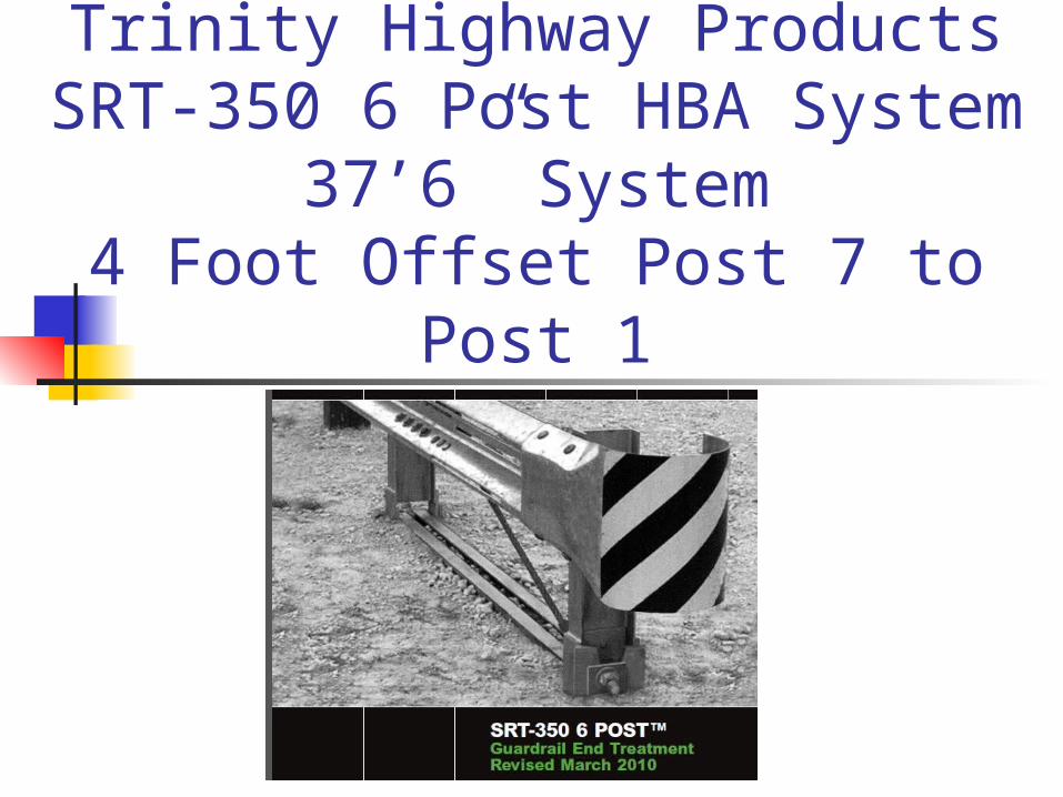
Trinity Highway ProductsSRT-350 6 Post HBA System
37’6” System4 Foot Offset Post 7 to Post 1

Trinity Highway Products Properly Installed SRT-350 6 Post HBA System-Slotted Rail
Terminal

Installation Instructionshttp://www.highwayguardrail.com/products/pdfs/SRT-350_6_Post.pdf
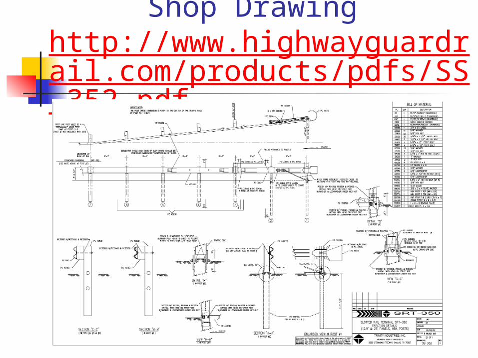
Shop Drawing http://www.highwayguardrail.com/products/pdfs/SS-352.pdf
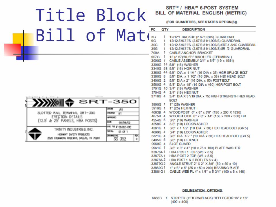
Title BlockBill of Materials
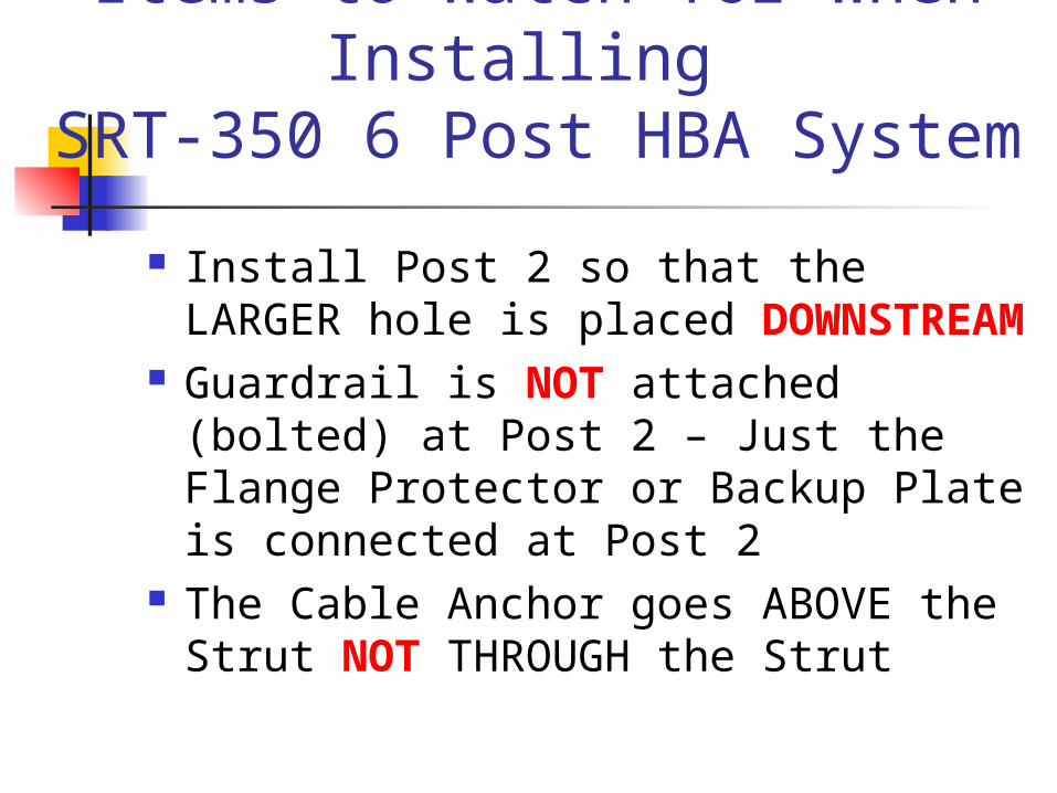
Items to Watch for when Installing
SRT-350 6 Post HBA System
Install Post 2 so that the LARGER hole is placed DOWNSTREAM
Guardrail is NOT attached (bolted) at Post 2 – Just the Flange Protector or Backup Plate is connected at Post 2
The Cable Anchor goes ABOVE the Strut NOT THROUGH the Strut

Post 3-6 CRT (Controlled Release Post) with 8” Offset
Blocks Install the CRT Post with 3½” holes
Approximately @ Finished Grade Note: Post 7 is also a CRT Wood Post 4’0” Flair
Begin @ Post 7 face of Guardrail at Offset Block Measure 37’6” to the face of the Guardrail at
Post 1 – no Offset Block at Post 1 & 2 (HBA Post) 4’0” offset is measured at Post 1
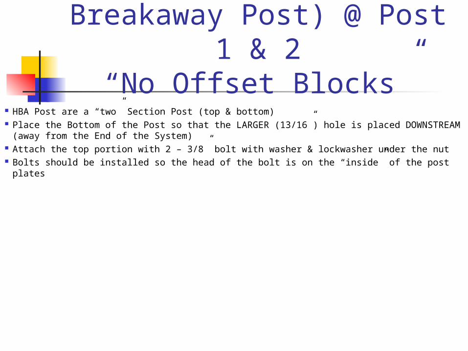
Installing HBA (Hinged Breakaway Post) @ Post 1
& 2“No Offset Blocks”
HBA Post are a “two” Section Post (top & bottom) Place the Bottom of the Post so that the LARGER (13/16”) hole is placed
DOWNSTREAM (away from the End of the System) Attach the top portion with 2 – 3/8” bolt with washer & lockwasher under the nut Bolts should be installed so the head of the bolt is on the “inside” of the post plates

Installing HBA (Hinged Breakaway Post) @ Post 1
Place Post 1 so that the LARGER hole is placed DOWNSTREAM (away from the End of the System)
Post 1
Note: Place the head of the bolts on the inside of the Post –washer, lock washer & nut on outside of Post
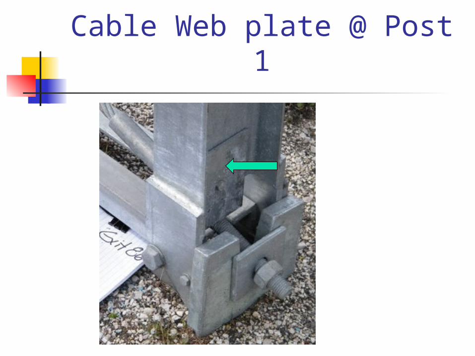
Cable Web plate @ Post 1

Installing HBA (Hinged Breakaway Post) @ Post 2
Place Post 2 so that the LARGER hole is placed DOWNSTREAM (away from the End of the System) Place the head of theBolts on the inside of the Post - washer, lock washer & nut on outside of Post
Post 2

Post 2 - Install Post so that the LARGER hole is placed
DOWNSTREAMIncorrect – Cannot HingeInstalled Backwards
Correct Placement - Can Properly Hinge
Post 2
Traffic

Post 2 -Place Post so that the LARGER hole is placed
DOWNSTREAM
Incorrect – Cannot HingeInstalled Backwards
Post 2 Traffic
Repair Incorrectly placed Post 2•Remove the Top of Post 2 and the Strut•Bottom of Post 2 MUST BEREMOVED (note the bottom of Post is not symmetrical and therefore cannot be drilled)•Properly backfill the hole •Rotated bottom of Post 2 180 degrees and re-drive the Post•Reattach the top portion of Post 2 and the Strut
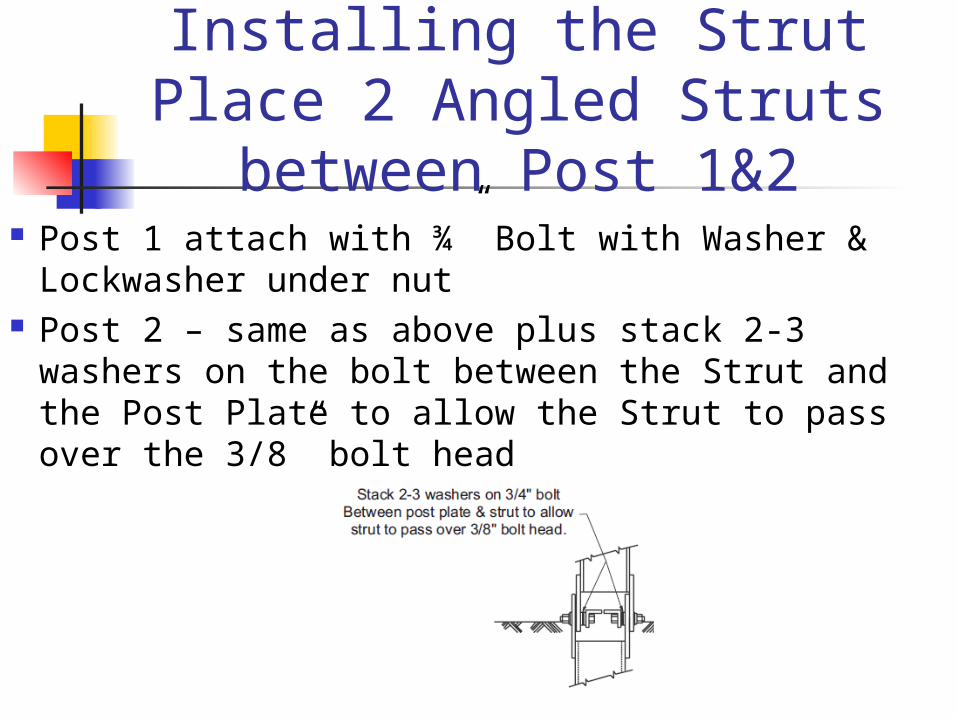
Installing the StrutPlace 2 Angled Struts
between Post 1&2 Post 1 attach with ¾” Bolt with Washer &
Lockwasher under nut Post 2 – same as above plus stack 2-3 washers
on the bolt between the Strut and the Post Plate to allow the Strut to pass over the 3/8” bolt head
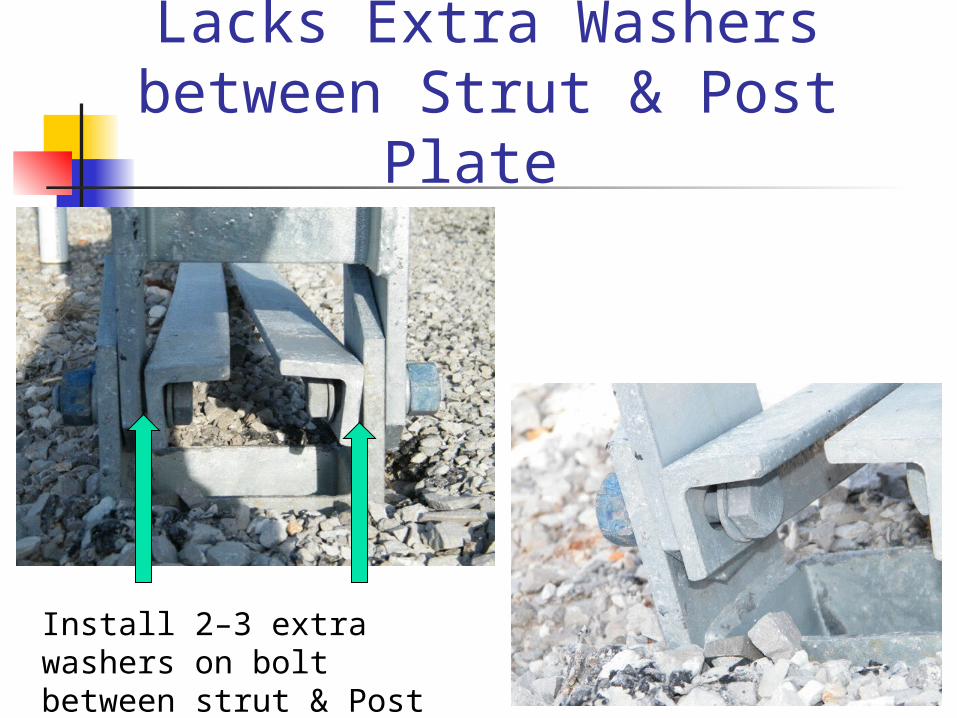
Post 2 with Bolt Heads Placed Inside Post - Lacks Extra Washers between Strut &
Post Plate
Install 2–3 extra washers on bolt between strut & Post
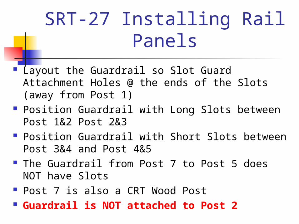
SRT-27 Installing Rail Panels
Layout the Guardrail so Slot Guard Attachment Holes @ the ends of the Slots (away from Post 1)
Position Guardrail with Long Slots between Post 1&2 Post 2&3
Position Guardrail with Short Slots between Post 3&4 and Post 4&5
The Guardrail from Post 7 to Post 5 does NOT have Slots
Post 7 is also a CRT Wood Post Guardrail is NOT attached to Post 2

Orientation of Slots, Slot Guards and Cable Anchor
Bracket
Slot Guards Away From Post 1
Connect to Wood CRT Post @ Post 7
No Slots Short Slots Long Slots
CableAnchor Bracket
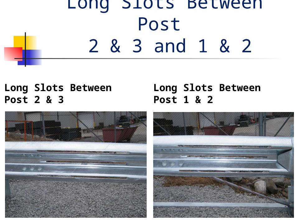
Long Slots Between Post 2 & 3 and 1 & 2
Long Slots BetweenPost 2 & 3
Long Slots BetweenPost 1 & 2

Short Slots Between Post 4 & 5 and 3 & 4
Short Slots BetweenPost 4 & 5
Short Slots BetweenPost 3 & 4

No Slots Between Post 6 & 7 and 5 & 6
No Slots BetweenPost 6 & 7
No Slots BetweenPost 5 & 6

Installing Rail PanelsContinued
Guardrail is attached to the Post through the Offset Blocks @ Post 3, 4, 5 and 6
Guardrail is not attached (bolted) at Post 2
Incorrectly BoltedCorrectly NOT Bolted
POST 2
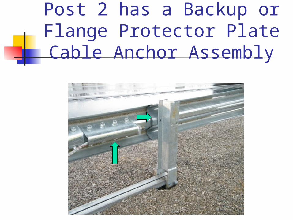
Post 2 has a Backup or Flange Protector Plate
Cable Anchor Assembly
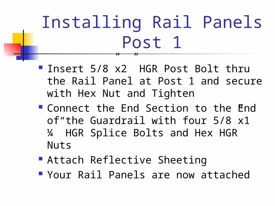
Installing Rail PanelsPost 1
Insert 5/8”x2” HGR Post Bolt thru the Rail Panel at Post 1 and secure with Hex Nut and Tighten
Connect the End Section to the End of the Guardrail with four 5/8”x1 ¼” HGR Splice Bolts and Hex HGR Nuts
Attach Reflective Sheeting Your Rail Panels are now attached
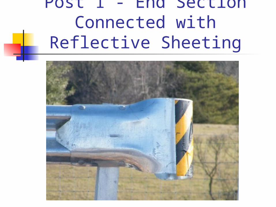
Post 1 - End Section Connected with Reflective
Sheeting
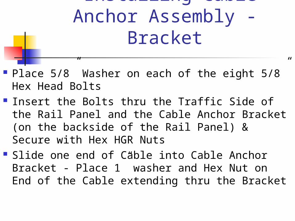
Installing Cable Anchor Assembly - Bracket
Place 5/8” Washer on each of the eight 5/8” Hex Head Bolts
Insert the Bolts thru the Traffic Side of the Rail Panel and the Cable Anchor Bracket (on the backside of the Rail Panel) & Secure with Hex HGR Nuts
Slide one end of Cable into Cable Anchor Bracket - Place 1” washer and Hex Nut on End of the Cable extending thru the Bracket
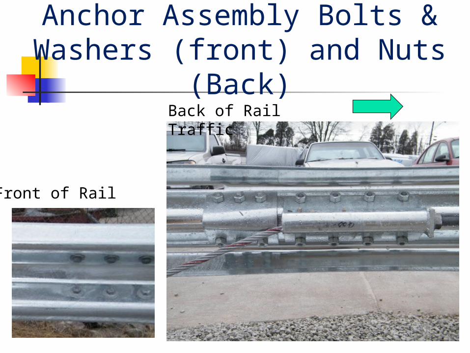
Front and Back of Cable Anchor Assembly Bolts & Washers (front) and Nuts
(Back)Back of Rail Traffic
Front of Rail

Install Cable Anchor Assembly – Post 1
Slide the other end of Cable between upper & lower sections of the HBA Post 1
On Post No. 1, bolt the 4"x5¾" x ¼” Cable Web Plate to the web of the post with a 3/8" x 1½” bolt, with a washer under the 3/8”nut. The Cable Web Plate should be pushing down on the top of the Shank of the Cable Anchor.

Cable Web plate @ Post 1 pushing down on the top of the Shank of the Cable
AnchorCable Web Plate pushing down on the top of the Shank of the Cable Anchor

Install Cable Anchor Assembly – Post 1
Place the Cable Bearing Plate with the open side of the V-Notch pointing upward and the Plate Washer on the end of the Cable.
The bearing plate should rest on the top of the flange of the HBA bottom post.

Cable Anchor Assembly – Post 1
“V” Bearing Plate rest on top of Flange of bottom of HBA
Post
Correct “V” Notch Up Incorrect“V” Notch Down
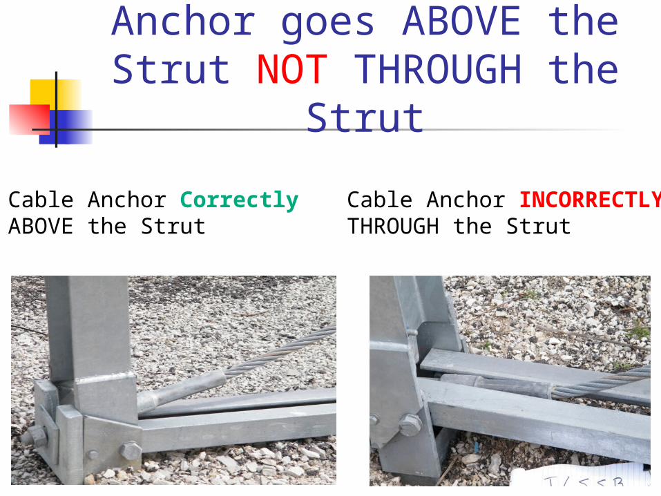
NOTE: The Cable Anchor goes ABOVE the Strut NOT
THROUGH the Strut
Cable Anchor CorrectlyABOVE the Strut
Cable Anchor INCORRECTLYTHROUGH the Strut
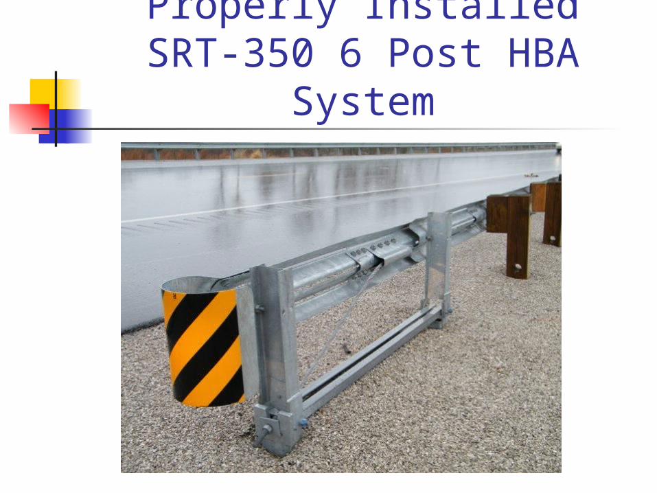
Properly InstalledSRT-350 6 Post HBA
System

Installation Instructionshttp://www.highwayguardrail.com/products/pdfs/SRT-350_6_Post.pdf

Shop Drawing http://www.highwayguardrail.com/products/pdfs/SS-352.pdf

Items to Watch for when Installing
SRT-350 6 Post HBA System
Install Post 2 so that the LARGER hole is placed DOWNSTREAM
Guardrail is NOT attached (bolted) at Post 2 – Just the Flange Protector or Backup Plate is connected at Post 2
The Cable Anchor goes ABOVE the Strut NOT THROUGH the Strut
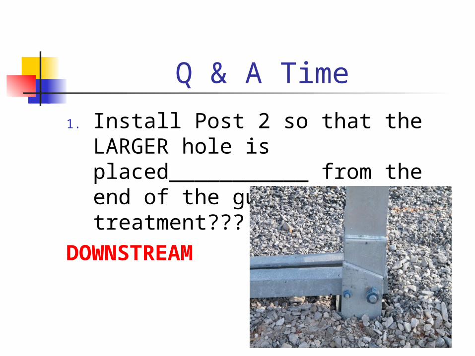
Q & A Time
1. Install Post 2 so that the LARGER hole is placed___________ from the end of the guardrail end treatment???
DOWNSTREAM
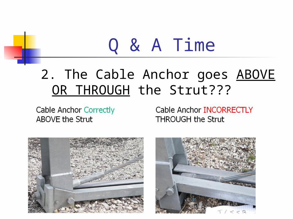
Q & A Time
2. The Cable Anchor goes ABOVE OR THROUGH the Strut???

Q & A Time
3. Guardrail IS or IS NOT attached (bolted) at Post 2???
IS NOT