Trigger adjustment QUick Set-up Guide - PAINT-SUPPLY.net · Turn SW1 “OFF” to resume...
12
Transcript of Trigger adjustment QUick Set-up Guide - PAINT-SUPPLY.net · Turn SW1 “OFF” to resume...


QUick Set-up Guide Connecting the air sourceThe Proton has a standard ASA to accept a screw in air tank. First, make sure that the knob is all the way out by turning it counterclockwise. Carefully screw in the air tank until it stops. Turning the knob clockwise will allow air to flow into the marker from the tank.To remove the tank, turn the knob counterclockwise. This will release all the air in the marker and make it safe to remove the tank. We recommend the use of compressed air or nitrogen air tank with a maximum output pressure of 800 PSI.
Attaching a loaderLoosen the screw on the clamping feed neck with a 5/32” hex key and insert the loader. Adjust it to the desired location and tighten.
Attaching the barrelThe barrel simply threads on. The barrel threads are autococker type.
Turning the marker ONThe electronic ON/OFF is located inside the trigger guard. Pull the knob outward to turn the board ON and push in to turn OFF. All three leds will come on for 2secs and the marker will be ready to fire in semi mode with the eyes on.
Adjusting the velocityThe Proton has an adjustable regulator in the handle frame that controls the pressure in the marker thereby controlling the velocity. The best way to adjust the velocity is to turn the adjusting screw clockwise using a 1/8” hex key. This will be the minimum velocity. Check the velocity with a chronograph and gradually increase the velocity by turning the screw counterclockwise.
Trigger adjustmentThe trigger has adjustments for pre travel, post travel and microswitch activation point. These are adjusted via the set screws in the trigger using a 1/16” hex key.
Adjustment procedure1. Ensure that the air is turned off to the marker.2. Turn the marker on3. Turn the eyes off. Now when you pull the trigger you will hear the
solenoid valve clicking.4. Adjust the pre and post travel position of the trigger to suit your liking.5. Pull the trigger and listen for the solenoid. Turn the set screw clockwise
until you hear the solenoid valve clicking. If you do not hear the solenoid then the screw may be too far in. Turn the trigger set screw counterclockwise until you hear the solenoid click when you pull the trigger.
6. Check for proper function by pulling and releasing the trigger.

Standard firing modesThe firing mode is changed by pressing the lower mode button. The green LED will indicate the current mode. Pressing the mode button again will cycle through the various modes. After 10 seconds the LED will turn off to save power.
Firing Mode Function Green LED DisplaySemi-Automatic One shot per trigger pull at a rate of fire (ROF) determined by the user setting. Blinking once slowly
3 Shot Burst Three shots are fired at a shot rate of 10 bps regardless if the eyes are on or off. The marker will fire the 3 shot string after the first trigger pull, regardless of trigger being held down.
3 quick blinks
Full Automatic Fires continuously at 10 bps while the trigger is pulled regardless if the eyes are on or off. Continuously blinking
Ramping 1 Fires in semi auto and ramps up to the max ROF when the trigger is pulled more than the ramp engage parameter. (Parameter 4)Ex. Ramp engage set to 5 bps. If the trigger is pulled more than 5 bps, the Proton will start firing at the max ROF setting.
Fading LED following by 1 blink
Ramping 2 Same as above with another ramp engage parameter setting.(Parameter 5)
Fading LED following by 2 blinks
Intelligent break beam ball sensor systemThe Proton has a break beam sensor system with eye shields that prevent any dirt from entering the sensor. The eyes can be cleaned by simply removing the bolt and using a squeegee. If any malfunction should occur the software automatically overrides the eye function and reduces the rate of fire. The upper mode button on the foregrip allows you to enable or disable the sensor system. The software detects the actual position of the ball as it approaches the bot-tom of the breech. This is a more reliable way of ensuring that the ball is in position rather than using a time delay. The in-position tolerance can be adjusted depending on the paintballs being used. If you are using relatively tough paintballs you can set the precision to low. A high precision will ensure that the ball is fully in the breech which would be useful for fragile paintballs. Refer to the user adjustable parameter section to change this setting.
Turning the ball sensor ON & OFFThe infrared ball sensor can be turned on and off by pressing the eye mode button. Briefly pressing the eye mode button will toggle the current status. The eye function is indicated by LED display in the following manner:
ORANGE LED, Single Blink Eye sensor ON
ORANGE LED, Two blinks Eye sensor OFF

Eye Sensor Alarms:The Proton software monitors the ball sensor and reports an alarm if no ball is present or if the breech has not cleared in the allotted time. This may be due to debris blocking the sensor, the sensor not functioning or if the bolt is jammed. Ball sensor alarms are indicated by the red LED. When the Proton software detects a breech not cleared error the shot rate is automatically reduced to 12 balls per second. This allows you to use the marker even though the ball sensor is not working properly, unless the bolt is jammed. The Proton will continue to display an error while you are shooting. Refer to the troubleshooting section to clear the error.
Alarm Display-Red LED
No ball present 3 quick blinks
Breech not cleared 3 quick blinks followed by a solid light
Tournament Modes \ Tournament LockThe tournament modes are adjusted via the dip switch on the main board located in the foregrip. To access the board, remove the foregrip using a 1/8” hex key. Slide the foregrip off the marker. Use a small screwdriver to flip the switches to the desired setting. After you change the setting you will need to cycle the power on and off to load the new setting. The eye mode button and eye sensor function the same way as in standard mode. If there is any ball breakage or malfunction of the sensors the software will override the shot rate and reduce it to 12 balls per second. The first dipswitch, SW1, when engaged\turned “ON”, will lock the board from being programmed from the trigger or via the mode button. If SW1 is engaged\turned “ON” without any other dipswitches engaged, it will lock the marker with whatever parameters you have configured before engaging the tournament lock. Turn SW1 “OFF” to resume programming the gun through the trigger or cycling through modes with the mode button on the foregrip.
Tournament Mode SW1 SW2 SW3 SW4NPPL \ Semi Auto: One shot per pull, capped at 15 BPS. (SW1 prevents changes \ engages tournament lock)
ON ON OFF OFF
PSP3: Three semi shots then transitions to 3 rounds burst. Capped at 12.5 bps. After 1 sec-ond idle, returns to semi auto. (SW1 prevents changes \ engages tournament lock)
ON OFF ON OFF
MILLENNIUM: Three semi shots then transitions to 3 rounds burst—6 pulls per second rate of fire must be pulled for burst to continue. Capped at 12 bps. Reverts to semi if pull rate drops below 6 pulls-per-second. (SW1 prevents changes \ engages tournament lock)
ON OFF OFF ON

User Adjustable ParametersThe parameters can be adjusted through the mode buttons and trigger. The settings are saved into the non volatile memory.
Changing The ParametersHold the trigger down while turning the marker on by pulling the safety switch out. All three LEDs will blink indicating that you are in programming mode.You can cycle through the parameters by pulling the trigger. The parameter type is indicated by a combination of colored LEDS. After you have selected the parameter you wish to change, hold down the trigger for two seconds. The corresponding LEDs will then flash a number of times, indicating the current value that the parameter has been configured to. All LEDs will then go dark—waiting for input from the trigger. Pull and release the trigger the amount you want to change the value to (e.g., pulling trigger 15 times = 15 balls per second). After you have pulled the trigger the desired amount of times, allow the gun to sit idle for 5 seconds. The setting is now changed.
Parameter RED LED ORANGE LED GREEN LED Range Default SettingShot Rate ON OFF OFF 10.0 to 30 in 1 BPS increments 25 bps
Solenoid Dwell OFF ON OFF 3ms to 15 ms1 ms increments
6 ms
Trigger Debounce ON ON OFF 2 ms to 10 ms1 ms increments
2 ms
Ramp 1 Engage OFF OFF ON 3 to 8 trigger pulls per second (pps)1 pps increments
6 bps
Ramp 2 Engage ON OFF ON 3 to 8 trigger pulls per second (pps)1 pps increments
8 pps
Ball In Position Accuracy OFF ON ON Low (1)Medium (2)High (3) - recommended for fragile paint
Medium (2)
Programming Procedure ExampleYour Proton comes out of the box capped at 25 bps. You want to reduce the rate of fire cap to 15 bps. Ensure your Proton does not have an air source or any paintballs in the marker. Hold down the trigger and turn the marker on to boot the marker into programming mode. All of the LEDs will flash to indicate that you are in programming mode. The first\upper LED will then turn solid red—indicating you are on the “Shot Rate” parameter. (If you wanted to cycle to another parameter, you would pull and release the trigger to cycle through the parameters). Hold down the trigger for 2 seconds. The red LED will then flash 25 times—indicating that the parameter was configured at 25 bps. The LED will then go dark—waiting for trigger input. Pull and release the trigger 15 times to change the parameter to 15bps. Allow the gun to sit for 5 seconds and your parameter will be saved. Turn the gun off, and boot as normal to use your new configuration.

FeaturesInline bolt systemThe Proton inline bolt system consists of a spool controlled by a direct operated solenoid valve. The movable part of the spool glides on self lubricating material which eliminates the need to use special grease like other spool type bolts. The low operating pressure and built in air cushion minimize recoil while firing.
Eye shieldsWhen a paintball breaks in a marker you almost always have to remove the bolt to completely clean out all the mess. Very rarely will it clean out by itself. And you will also have to remove the eyes to clean them properly. This is why the eye shields are so useful. When you use a squeegee to clean out the breech this will also clean the eyes. In addition they are slightly recessed so they will never get scratched by the movement of the bolt.
ASA with on/off and purge systemThe Proton has a standard threaded ASA with an ON/OFF knob that not only makes it safe to remove the tank but also releases all the air in the marker and dump chamber. This simple and useful feature eliminates the need to shoot out the air in the marker when you remove the tank.
Intelligent break beam sensor systemThe Proton has a redesigned break beam sensor system with eye shields that prevent any dirt from interfering with the sensor. The eyes can be cleaned by simply removing the bolt and using a squeegee. If any malfunction should occur the software automatically overrides the eye function and reduces the rate of fire to keep you in the game. The upper mode button on the foregrip allows you to enable or disable the sensor system. The software detects the actual position of the ball as it approaches the bottom of the breech. This is a more reliable way of ensuring that the ball is in position rather than using a time delay. The in-position tolerance can be adjusted depending on the paintballs being used. If you are using relatively tough paintballs you can set the precision to low. A high precision will ensure that the ball is fully in the breech which would be useful for fragile paintballs.
Electronic On/OffWe have built in a convenient electrical on/off switch into the handle that cuts off all power from the battery. Unlike other electronic markers ,when you are not using your marker you do not have to worry about draining the battery. We have also eliminated those cumbersome 9 volt battery connectors; the battery simply snaps into the handle frame.
Simple designThe Proton has all the air lines machined in the handle eliminated those bulky and leak prone macro fittings. The electronic controls and status leds are conveniently located in the foregip. The inline bolt system is completely removable from the back of the marker.
Adjustable triggerThe trigger has adjustments for pre and post travel as well as microswitch activation point.

Firing modesThere are 5 firing modes and 4 tournament modes. You can adjust the settings through the foregrip control without removing any covers.
Maintaining your ProtonThe Proton has been designed to require a minimal amount of maintenance for proper operation. It is recommended that before each use you put 2 drops of light gun oil in the ASA. When the marker is gassed up the oil will distribute through the marker. This will be adequate to keep the marker working properly.
Removing the ball detents for cleaningThe Proton uses two spring loaded ball detents to prevent the double feeding of paintballs. They are located near the front of the receiver. To remove, insert a 1/16” hex key into the access hole in the cover. Make sure that the hex key is fully engaged in the screw otherwise you may strip the hex in the screw. Unscrew the cover and lift out the ball detent and spring.
To install the ball detent• Place the ball detent in the hole in the receiver.• Put the spring in the ball detent,• Put the cover screw in the slot of the cover and put the hex key in the screw through the access hole in the cover.• Place the cover over the ball detent and spring.• Tighten the screw.
Note: Do not over-tighten the screw otherwise you may strip the hex in the screw which will make it difficult to remove the cover.
Cleaning the ProtonFirst remove the bolt assembly by inserting a 5/32” hex key in the rear cap. Unscrew the bolt assembly and pull it out. You can use a standard squeegee to clean the bore of the marker. Insert the squeegee from the back of the marker and pull it through the front.
Battery replacementRemove the four screws hold the wraparound grip and push the battery out from the access hole on the handle frame. Note the proper polarity when installing a new battery. The + side of the battery is indicated on the board in the handle frame. We recommend the use of a high quality alkaline battery.
Removing the frame from the bodyIn the event that you need to separate the frame and body, ensure that you unplug the wiring harness (the two small wires with white plastic connector blocks on either side) from the circuit board in the grip frame ONLY. While removing the wiring harness from your upper\horizontal board will not permanently damage your marker, it is very difficult to replace correctly and can result in damage if it is not replaced carefully.
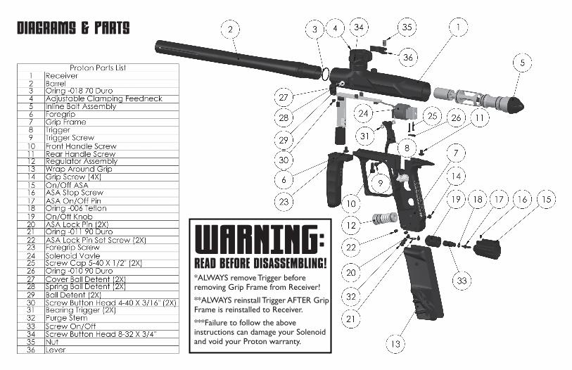
Diagrams & PArts
WARNING:READ BEFORE DISASSEMBLING!*ALWAYS remove Trigger before removing Grip Frame from Receiver!
**ALWAYS reinstall Trigger AFTER Grip Frame is reinstalled to Receiver.
***Failure to follow the above instructions can damage your Solenoid and void your Proton warranty.

5a 5b
5d
5c 5e 5f
5h 5i
5g 5j 5k
5l 5m 5n 5o 5p
5q 5r5c
12a 12b 12c 12d 12e 12f 12g 12h 12i 12j
Incline Bolt Assembly5a Bolt Head5b Oring M1 X 145c Oring -018 70 Duro5d Front U Cup Seal5e Front Sleeve5f Oring -109 70 Duro5g Front Cap5h Oring M1 X 125i Front Bumper5j Rear Shaft5k Oring -010 70 Duro5l Oring -016 70 Duro
5m Rear Sleeve5n Screw Set 6-32 X 3/16"5o Rear Shaft Seat5p Rear Cushion5q Oring M1 X 16.55r Rear Cushion Cap
Regulator Assembly12a C-Clip12b Adjusting Screw Seal12c Adjusting Screw12d Regulator Stem Seal12e Regulator Cap12f Oring -014 70 Duro12g Oring -011 70 Duro12h Regulator Spring12i Regulator Stem12j Oring -014 70 Duro
Bolt Assembly
Regulator Assembly

WARNING: Important Safety InstructionsThis is not a toy. Misuse may cause serious injury or death. Eye protection designed specifically for paintball must be worn by the user and persons within range. Recommend 18 years of age or older to purchase. Persons under 18 years of age must have adult supervision.
READ OWNERS MANUAL BEFORE USING.Rules of Safe Marker Handling”1. Treat every marker as if it were loaded.2. Never look down the barrel of a paintball marker.3. Keep your finger off the trigger until ready to shoot.4. Never point the marker at anything you don’t wish to shoot.5. Keep the marker on “safe” until ready to shoot.6. Keep the barrel blocking device in/on the marker’s muzzle when not shooting.7. Always remove paintballs and propellant source before disassembly.8. After removing propellant source, point marker in safe direction and discharge until marker is degassed.9. Store the marker unloaded and degassed in a secure place.10. Follow warnings listed on propellant source for handling and storage.11. Do not shoot at fragile objects such as windows.12. Every person within range must wear eye, face and ear protection designed specifically to stop paintballs and meeting ASTM standard F1776.13. Always measure your marker’s velocity before playing paintball and never shoot at velocities in excess of 300 feet-per-second.

LIMITED WARRANTYValken Paintball guarantees the Proton against defects in material and/or workmanship of this marker for twelve (12) months from the original date of purchase by the origi-nal retail purchaser. To activate your warranty, fill out the warranty card and mail it along with a copy of the original purchase receipt. In the event that a part is defective Valken Sports will send out a replacement part free of charge. Wearable items such as o-rings, screws, ball detents and the like are not covered under this warranty. Failure of any part due to an accident, abuse, neglect, modification, misuse, operator error, lack of maintenance, or use of parts incon-sistent with the use originally intended for the marker as sold is not covered by this warranty.
Valken makes no other warranties or guarantees, expressed or implied. Valken Paintball limits its sole and exclusive li-ability and that of it’s authorized dealers, affiliates, or agents pursuant to this warranty to cover repair or replacement of the defective part. Incidental and consequential damages are expressly excluded hereunder. Valken Paintball, its autho-rized dealers, affiliates, or agents, will not be liable under this warranty, nor under any state or federal law, or the com-mon law or otherwise for any damage or failure, including personal injury, resulting from such use and/or alteration. This warranty gives you specific legal rights, and you may also have other rights that may vary from state to state.
(856) 812-2800 • www.valkenpaintball.com
Warranty Registration CardName ________________________________________________________
Address ______________________________________________________
City _________________________________________________________
State/Province _________________________________________________
Zip Code _____________________________________________________
Country ______________________________________________________
Phone _______________________________________________________
E-Mail _______________________________________________________
Purchased from ________________________________________________
Store location __________________________________________________
Purchase price _________________________________________________
For warranty parts, service or information contact:Valken Paintball • 1 Hawk Court • Swedesboro NJ 08085(856) 812-2800 • www.valkenpaintball.com
To activate your warranty, fill out & Detach this warranty card and mail it along with a copy of the original purchase receipt to valken.

Valken Sports, Inc.1 Hawk Court
Swedesboro, NJ. 08085