TRF-100 - Doble Engineering Company
4
TRF-100 automatic, 3-phase transformer turns ratio finder
Transcript of TRF-100 - Doble Engineering Company

TRF-100automatic, 3-phase transformer turns ratio finder
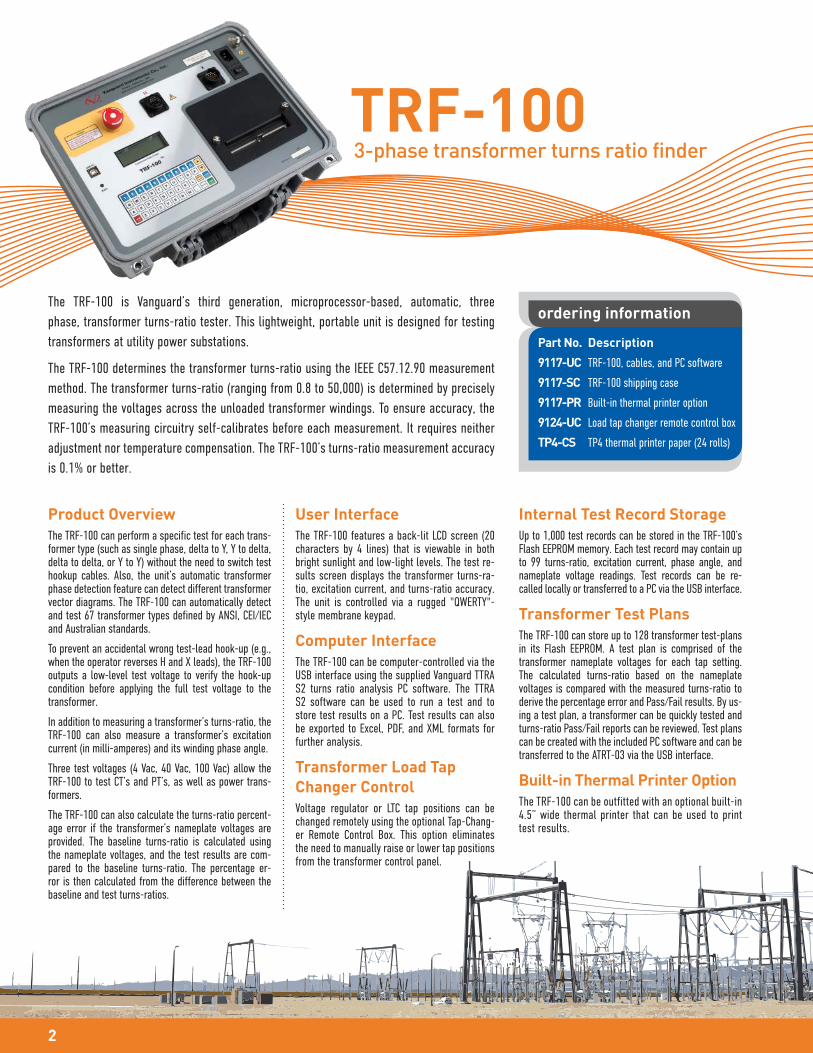
TRF-1003-phase transformer turns ratio finder
2
The TRF-100 is Vanguard’s third generation, microprocessor-based, automatic, three
phase, transformer turns-ratio tester. This lightweight, portable unit is designed for testing
transformers at utility power substations.
The TRF-100 determines the transformer turns-ratio using the IEEE C57.12.90 measurement
method. The transformer turns-ratio (ranging from 0.8 to 50,000) is determined by precisely
measuring the voltages across the unloaded transformer windings. To ensure accuracy, the
TRF-100’s measuring circuitry self-calibrates before each measurement. It requires neither
adjustment nor temperature compensation. The TRF-100’s turns-ratio measurement accuracy
is 0.1% or better.
Product Overview
The TRF-100 can perform a specific test for each trans-former type (such as single phase, delta to Y, Y to delta, delta to delta, or Y to Y) without the need to switch test hookup cables. Also, the unit’s automatic transformer phase detection feature can detect different transformer vector diagrams. The TRF-100 can automatically detect and test 67 transformer types defined by ANSI, CEI/IEC and Australian standards.
To prevent an accidental wrong test-lead hook-up (e.g., when the operator reverses H and X leads), the TRF-100 outputs a low-level test voltage to verify the hook-up condition before applying the full test voltage to the transformer.
In addition to measuring a transformer’s turns-ratio, the TRF-100 can also measure a transformer’s excitation current (in milli-amperes) and its winding phase angle.
Three test voltages (4 Vac, 40 Vac, 100 Vac) allow the TRF-100 to test CT’s and PT’s, as well as power trans-formers.
The TRF-100 can also calculate the turns-ratio percent-age error if the transformer’s nameplate voltages are provided. The baseline turns-ratio is calculated using the nameplate voltages, and the test results are com-pared to the baseline turns-ratio. The percentage er-ror is then calculated from the difference between the baseline and test turns-ratios.
User Interface
The TRF-100 features a back-lit LCD screen (20 characters by 4 lines) that is viewable in both bright sunlight and low-light levels. The test re-sults screen displays the transformer turns-ra-tio, excitation current, and turns-ratio accuracy. The unit is controlled via a rugged "QWERTY"-style membrane keypad.
Computer Interface
The TRF-100 can be computer-controlled via the USB interface using the supplied Vanguard TTRA S2 turns ratio analysis PC software. The TTRA S2 software can be used to run a test and to store test results on a PC. Test results can also be exported to Excel, PDF, and XML formats for further analysis.
Transformer Load Tap
Changer Control
Voltage regulator or LTC tap positions can be changed remotely using the optional Tap-Chang-er Remote Control Box. This option eliminates the need to manually raise or lower tap positions from the transformer control panel.
Internal Test Record Storage
Up to 1,000 test records can be stored in the TRF-100’s Flash EEPROM memory. Each test record may contain up to 99 turns-ratio, excitation current, phase angle, and nameplate voltage readings. Test records can be re-called locally or transferred to a PC via the USB interface.
Transformer Test Plans
The TRF-100 can store up to 128 transformer test-plans in its Flash EEPROM. A test plan is comprised of the transformer nameplate voltages for each tap setting. The calculated turns-ratio based on the nameplate voltages is compared with the measured turns-ratio to derive the percentage error and Pass/Fail results. By us-ing a test plan, a transformer can be quickly tested and turns-ratio Pass/Fail reports can be reviewed. Test plans can be created with the included PC software and can be transferred to the ATRT-03 via the USB interface.
Built-in Thermal Printer Option
The TRF-100 can be outfitted with an optional built-in 4.5” wide thermal printer that can be used to print test results.
ordering information
Part No. Description
9117-UC TRF-100, cables, and PC software
9117-SC TRF-100 shipping case
9117-PR Built-in thermal printer option
9124-UC Load tap changer remote control box
TP4-CS TP4 thermal printer paper (24 rolls)

3
TRF-100 Controls & IndicatorsThermal Printer Output
Desktop Printer Output
emergencyturn off switch
connector forH terminals
4.5” widethermal printer
powerswitch
groundstud
ruggedmembrane keypad
USBPC interface
connector forX terminals
back-lit LCD screen(20 characters by 4 lines)
TRF-100 technical specifications
physicalspecifications
Dimensions: 17”W x 7”H x 13” D (43.2 cm x 17.8 cm x 33.0 cm)Weight: 14 lbs. (6.4 Kg)
ratio measuringrange
0.8 ¬ 50,000 : 1 (5-digit resolution)measuringmethod
ANSI/IEEE C57.12.90
typicalturns-ratioaccuracy
4 Vac: 0.8 ¬ 1,000 (±0.08%), 1,001 ¬ 4,000 (±0.1%), 4,001 ¬ 15,000 (±0.25%)40 Vac: 0.8 ¬ 1,000 (±0.05%), 1,001 ¬ 4,000 (±0.1%), 4,001 ¬ 15,000 (±0.25%), 15,001 ¬ 20,000 (±0.4%), 20,001 ¬ 50,000 (±0.5%)100 Vac: 0.8 ¬ 1,000 (±0.05%), 1,001 ¬ 4,000 (±0.1%), 4,001 ¬ 15,000 (±0.25%), 15,001 ¬ 20,000 (±0.4%), 20,001 ¬ 50,000 (±0.5%)
NOTE : the above specifications are valid at nominal voltage and ambient temperature of +25°C (+77°F). Specifications are subject to change without notice.
inputpower
100 ¬ 240 Vac, 50/60 Hz, 3 Amps
testvoltages
4 Vac @ 1.0A, 40 Vac @ 0.6A, 100 Vac @ 0.1A currentreading range
0 ¬ 2 Amperes; Resolution: ±1mA
Accuracy: ±2% of reading (±1 digit)
phase anglemeasurement
0 ¬ 360 degreesaccuracy: ±0.2 degree (±1 digit)
display back-lit LCD screen (20 characters by 4 lines)viewable in bright sunlight and low-light levels
printer optional built-in 4K” wide thermal printer computerinterface
USB PC interface
pcsoftware
Windows®-based transformer turns-ratio analysis software is included with purchase
internal testplan storage
stores up to 128 transformer test plans100
010
110
internal testrecord storage
stores 1,000 complete transformer test records, each including nameplate voltage, turns-ratios, excitation current, and winding phase angle
100
010
110
safety designed to meet IEC 61010 (1995),UL 61010A-1, and CSA-C22.2 standards!
temperature Operating: -10°C to +50°C (+15°F to +122°F)Storage: -30°C to +70°C (-22°F to +158°F)
humidity 90% RH @ 40°C (104°F) non-condensing
altitude 2,000 m (6,562 ft)to full safety specifications
cables 15 ft (4.6m) single phase cable set, 15 ft (4.6m) 3-phase cable set, 25 ft (7.6m) extension cable set, USB cable, power & ground cables, cable bag
options shipping case, transformer load tap-changer remote control device, 30'
(9.14 m) single and 3-phase H and X leads
warranty one year on parts and labor

Instruments designed and developed
by the hearts and minds of utility
electricians around the world.
Founded in 1991 and located in Ontario, California, USA, Vanguard InstrumentsTM offers
a wide range of diagnostic test equipment that accurately and efficiently measures the
health of critical substation equipment, such as transformers, circuit breakers, and
protective relays.
Our first product was a computerized, extra high voltage (EHV) circuit breaker analyzer,
which became the forerunner of an entire line of EHV circuit breaker test equipment.
Over the years, our portfolio has grown tremendously to include microcomputer-based
precision micro-ohmmeters; single- and three-phase transformer winding turns-ratio
testers; transformer winding-resistance meters; mega-ohm resistance meters; and a
variety of other application-specific products.
Our instruments are rugged, reliable, accurate, and user friendly. They eliminate
tedious and time-consuming operations, while providing fast, complex test-result
calculations. Using our equipment helps reduce errors and eliminates the need to
memorize long sequences of procedural steps.
In 2017, Vanguard Instruments became a part of Doble Engineering Company, an
energy industry leader in hardware, software, and services that diagnose and monitor
the health of critical assets.
1520 S. Hellman Avenue
Ontario, California 91761, USA
Phone 909-923-9390 • Fax 909-923-9391
www.vanguard-instruments.com
Revision C. March 16, 2018
© Copyright 2018 Doble Engineering Company