EMC TRF Template
28
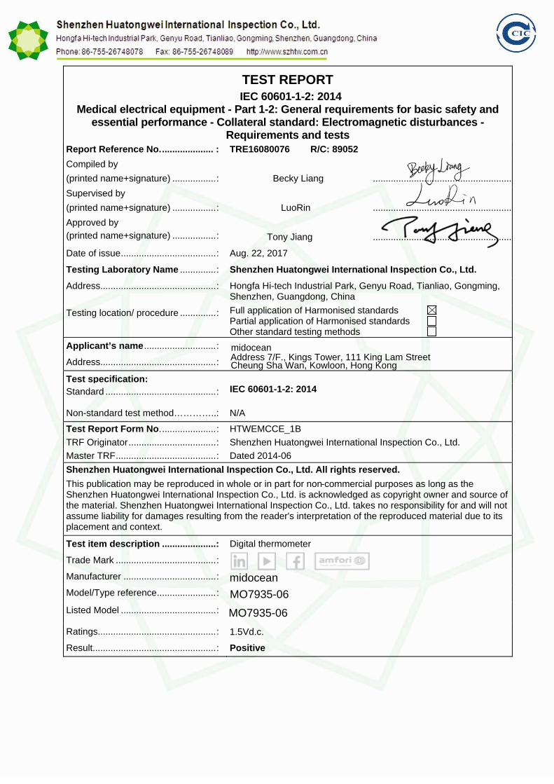
TEST REPORT IEC 60601-1-2: 2014 Medical electrical equipment - Part 1-2: General requirements for basic safety and essential performance - Collateral standard: Electromagnetic disturbances - Requirements and tests Report Reference No. .................... : TRE16080076 R/C: 89052 Compiled by (printed name+signature) ................. : Becky Liang ...................................................... Supervised by (printed name+signature) ................. : LuoRin ...................................................... Approved by (printed name+signature) ................. : Tony Jiang ...................................................... Date of issue..................................... : Aug. 22, 2017 Testing Laboratory Name .............. : Shenzhen Huatongwei International Inspection Co., Ltd. Address............................................. : Hongfa Hi-tech Industrial Park, Genyu Road, Tianliao, Gongming, Shenzhen, Guangdong, China Testing location/ procedure .............. : Full application of Harmonised standards Partial application of Harmonised standards Other standard testing methods Applicant’s name ............................ : Address............................................. : Test specification: Standard ........................................... : IEC 60601-1-2: 2014 Non-standard test method…………..: N/A Test Report Form No. ..................... : HTWEMCCE_1B TRF Originator .................................. : Shenzhen Huatongwei International Inspection Co., Ltd. Master TRF....................................... : Dated 2014-06 Shenzhen Huatongwei International Inspection Co., Ltd. All rights reserved. This publication may be reproduced in whole or in part for non-commercial purposes as long as the Shenzhen Huatongwei International Inspection Co., Ltd. is acknowledged as copyright owner and source of the material. Shenzhen Huatongwei International Inspection Co., Ltd. takes no responsibility for and will not assume liability for damages resulting from the reader's interpretation of the reproduced material due to its placement and context. Test item description .....................: Digital thermometer Trade Mark ....................................... : Manufacturer .................................... : Model/Type reference....................... : Listed Model ..................................... : Ratings.............................................. : 1.5Vd.c. Result................................................ : Positive midocean Address 7/F., Kings Tower, 111 King Lam Street Cheung Sha Wan, Kowloon, Hong Kong midocean MO7935-06 MO7935-06
Transcript of EMC TRF Template
TEST REPORT IEC 60601-1-2: 2014
Medical electrical equipment - Part 1-2: General requirements for basic safety and essential performance - Collateral standard: Electromagnetic disturbances -
Requirements and tests Report Reference No. .................... : TRE16080076 R/C: 89052 Compiled by (printed name+signature) ................. :
Becky Liang
......................................................
Supervised by (printed name+signature) ................. :
LuoRin
......................................................
Approved by (printed name+signature) ................. :
Tony Jiang
......................................................
Date of issue ..................................... : Aug. 22, 2017
Testing Laboratory Name .............. : Shenzhen Huatongwei International Inspection Co., Ltd. Address............................................. : Hongfa Hi-tech Industrial Park, Genyu Road, Tianliao, Gongming,
Shenzhen, Guangdong, China
Testing location/ procedure .............. : Full application of Harmonised standards Partial application of Harmonised standards Other standard testing methods
Applicant’s name ............................ : Address............................................. :
Test specification: Standard ........................................... : IEC 60601-1-2: 2014
Non-standard test method…………..: N/A
Test Report Form No. ..................... : HTWEMCCE_1B TRF Originator .................................. : Shenzhen Huatongwei International Inspection Co., Ltd. Master TRF ....................................... : Dated 2014-06 Shenzhen Huatongwei International Inspection Co., Ltd. All rights reserved. This publication may be reproduced in whole or in part for non-commercial purposes as long as the Shenzhen Huatongwei International Inspection Co., Ltd. is acknowledged as copyright owner and source of the material. Shenzhen Huatongwei International Inspection Co., Ltd. takes no responsibility for and will not assume liability for damages resulting from the reader's interpretation of the reproduced material due to its placement and context.
Test item description .....................: Digital thermometer
Trade Mark ....................................... :
Manufacturer .................................... :
Model/Type reference ....................... :
Listed Model ..................................... :
Ratings.............................................. : 1.5Vd.c.
Result ................................................ : Positive
midoceanAddress 7/F., Kings Tower, 111 King Lam StreetCheung Sha Wan, Kowloon, Hong Kong
midocean
MO7935-06
MO7935-06
Report No.: TRE16080076 Page 2 of 28 Issued: 2017-08-22
EMC -- T E S T R E P O R T
Test Report No. : TRE16080076 Aug. 22, 2017 ______________________________________________________________________________________________
Date of issue
Equipment under Test : Digital thermometer
Model /Type :
Listed Model :
Applicant :
Address :
Manufacturer :
Address :
Test Result according to the standards on page 4:
Positive
The test report merely corresponds to the test sample. It is not permitted to copy extracts of these test result without the written permission of the test laboratory.
midocean
midocean
Address 7/F., Kings Tower, 111 King Lam Street, Cheung Sha Wan, Kowloon, Hong Kong
Address 7/F., Kings Tower, 111 King Lam Street, Cheung Sha Wan, Kowloon, Hong Kong
MO7935-06
MO7935-06
Report No.: TRE16080076 Page 3 of 28 Issued: 2017-08-22
Contents
1 .
2 .
T E S T S T A N D A R D S . . . . . . . . . . . . . . . . . . . . . . . . . . . . . . . . . . . . . . . . . . . . . . . . . . . . . . . . . . . . . . . . . . . . 4
2.1. General Remarks
S U M M A R Y . . . . . . . . . . . . . . . . . . . . . . . . . . . . . . . . . . . . . . . . . . . . . . . . . . . . . . . . . . . . . . . . . . . . . . . . . . . . . . . 5
5 2.2. Equipment Under Test 5 2.3. Short description of the Equipment under Test (EUT) 5 2.4. EUT operation mode 5 2.5. EUT configuration 5 2.6. IMMUNITY pass/fail criteria 6
3 .
3.1. Address of the test laboratory
T E S T E N V I R O N M E N T . . . . . . . . . . . . . . . . . . . . . . . . . . . . . . . . . . . . . . . . . . . . . . . . . . . . . . . . . . . . . . . . . 7
7 3.2. Test Facility 7 3.3. Environmental conditions 8 3.4. Test Description 8 3.5. Statement of the measurement uncertainty 13 3.6. Equipments Used during the Test 13
4 .
4.1. Radiated Emission
T E S T C O N D I T I O N S A N D R E S U L T S . . . . . . . . . . . . . . . . . . . . . . . . . . . . . . . . . . . . . . . . . . . . . . 1 5
15 4.2. Conducted disturbance 19 4.3. Harmonic current 19 4.4. Voltage Fluctuation and Flicker 19 4.5. Electrostatic discharge 19 4.6. Radiated, radio-frequency, electromagnetic field 22 4.7. Electrical fast transients / Burst 24 4.8. Surge 24 4.9. Conducted disturbances induced by radio-frequency fields 24 4.10. Magnetic Field Immunity 25 4.11. Voltage Dips and Interruptions 26
5 .
5.1. External photos of the EUT
E X T E R N A L A N D I N T E R N A L P H O T O S O F T H E E U T . . . . . . . . . . . . . . . . . . . . . . . . . 2 7
27 5.2. Internal photos of the EUT 28
Report No.: TRE16080076 Page 4 of 28 Issued: 2017-08-22 1 . T E S T S T A N D A R D S The tests were performed according to following standards: IEC 60601-1-2: 2014 Medical electrical equipment - Part 1-2: General requirements for basic safety and essen
tial performance - Collateral standard: Electromagnetic disturbances - Requirements and tests
Remark: This EUT is ranged to the Group 1 Class B apparatus according to the standard of CISPR 11: 2010
clause 5.2
Report No.: TRE16080076 Page 5 of 28 Issued: 2017-08-22 2 . S U M M A R Y
2.1. General Remarks: Date of receipt of test sample : Aug. 15, 2017 Testing commenced on : Aug. 15, 2017 Testing concluded on : Aug. 22, 2017
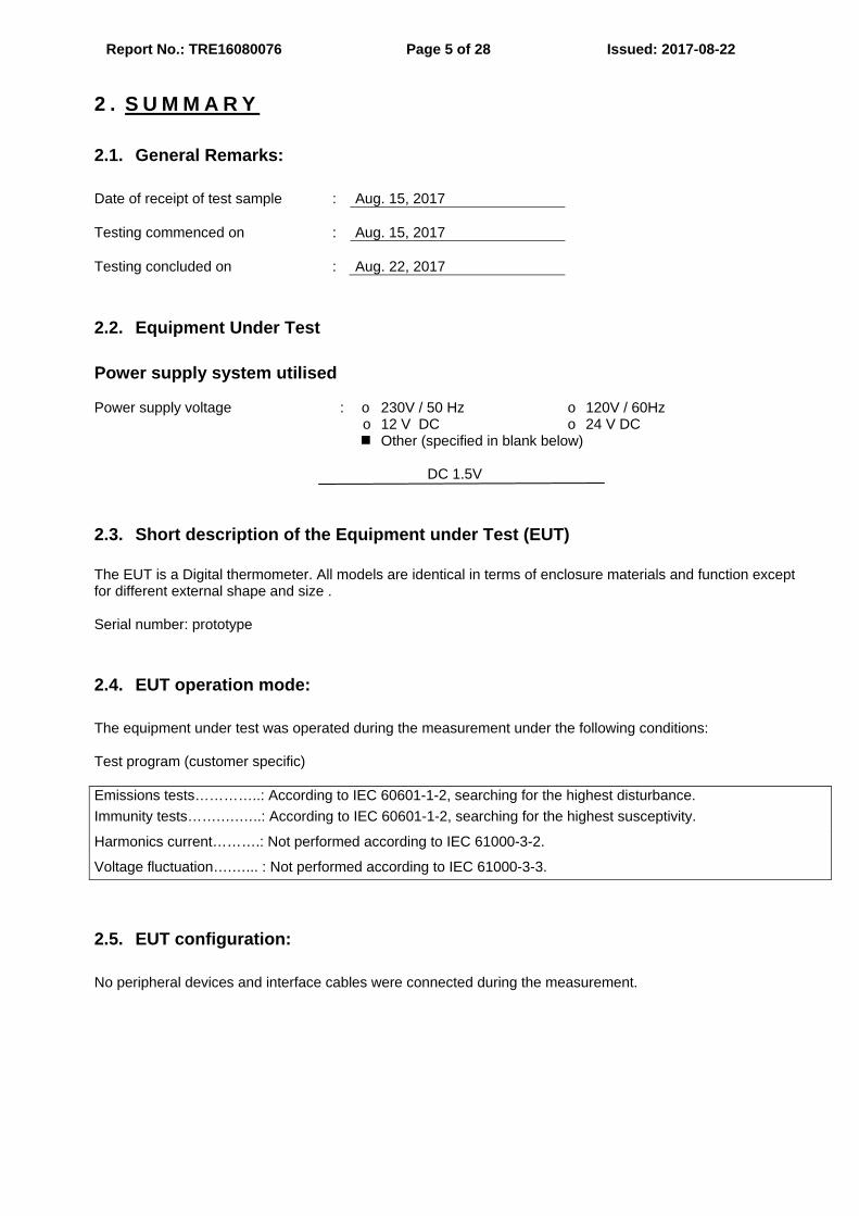
2.2. Equipment Under Test Power supply system utilised Power supply voltage : o 230V / 50 Hz o 120V / 60Hz o 12 V DC o 24 V DC Other (specified in blank below) DC 1.5V
2.3. Short description of the Equipment under Test (EUT) The EUT is a Digital thermometer. All models are identical in terms of enclosure materials and function except for different external shape and size . Serial number: prototype
2.4. EUT operation mode: The equipment under test was operated during the measurement under the following conditions: Test program (customer specific) Emissions tests…………..: According to IEC 60601-1-2, searching for the highest disturbance. Immunity tests…….….…..: According to IEC 60601-1-2, searching for the highest susceptivity.
Harmonics current……….: Not performed according to IEC 61000-3-2.
Voltage fluctuation….…... : Not performed according to IEC 61000-3-3.
2.5. EUT configuration: No peripheral devices and interface cables were connected during the measurement.
Report No.: TRE16080076 Page 6 of 28 Issued: 2017-08-22
2.6. IMMUNITY pass/fail criteria: Examples of test failures: – malfunction; – non-operation when operation is required; – unwanted operation when no operation is required; – deviation from normal operation that poses an unacceptable RISK to the PATIENT or OPERATOR; – component failures; – change in programmable parameters; – reset to factory defaults (MANUFACTURER’s presets); – change of operating mode; – a FALSE POSITIVE ALARM CONDITION; – a FALSE NEGATIVE ALARM CONDITION (failure to alarm); – cessation or interruption of any intended operation, even if accompanied by an ALARM SIGNAL; – initiation of any unintended operation, including unintended or uncontrolled motion, even if accompanied by an ALARM SIGNAL; – error of a displayed numerical value sufficiently large to affect diagnosis or treatment; – noise on a waveform in which the noise would interfere with diagnosis, treatment or monitoring; – artefact or distortion in an image in which the artefact would interfere with diagnosis, treatment or monitoring; – failure of automatic diagnosis or treatment ME EQUIPMENT or ME SYSTEM to diagnose or treat, even if accompanied by an ALARM SIGNAL. Example of performance during and after the applied testing stimulus required to pass the test: – for a mammography system, the compression full release and associated command remains fully operational; – for ULTRASOUND DIAGNOSTIC EQUIPMENT, the probe heating, dissipative power and temperature shall remain within specifications; – safety-related functions perform as intended; – false operation of alarms, “fail safe” modes and similar functions do not occur. NOTE This might require performing the test twice – once to ensure the functions occur as expected and again to ensure they do not occur falsely. Examples of acceptable degradation: – an imaging system displays an image that could be altered, but in a way that would not affect the diagnosis or treatment; – a heart rate monitor displays a heart rate that could be in error, but by an amount that is not clinically significant; – a PATIENT monitor exhibits a small amount of noise or a transient on a waveform and the noise or transient would not affect diagnosis, treatment or monitoring. Examples of ME EQUIPMENT and ME SYSTEMS with multiple functions: – multi-parameter monitors; – anaesthesia system with monitors; – ventilators with monitors; – multiple instances of the same function (e.g. multiple invasive blood pressure sensors).
Report No.: TRE16080076 Page 7 of 28 Issued: 2017-08-22 3 . T E S T E N V I R O N M E N T
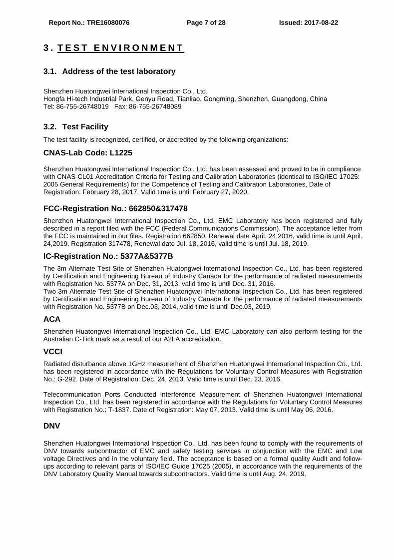
3.1. Address of the test laboratory Shenzhen Huatongwei International Inspection Co., Ltd. Hongfa Hi-tech Industrial Park, Genyu Road, Tianliao, Gongming, Shenzhen, Guangdong, China Tel: 86-755-26748019 Fax: 86-755-26748089
3.2. Test Facility The test facility is recognized, certified, or accredited by the following organizations:
CNAS-Lab Code: L1225
Shenzhen Huatongwei International Inspection Co., Ltd. has been assessed and proved to be in compliance with CNAS-CL01 Accreditation Criteria for Testing and Calibration Laboratories (identical to ISO/IEC 17025: 2005 General Requirements) for the Competence of Testing and Calibration Laboratories, Date of Registration: February 28, 2017. Valid time is until February 27, 2020.
FCC-Registration No.: 662850&317478 Shenzhen Huatongwei International Inspection Co., Ltd. EMC Laboratory has been registered and fully described in a report filed with the FCC (Federal Communications Commission). The acceptance letter from the FCC is maintained in our files. Registration 662850, Renewal date April. 24,2016, valid time is until April. 24,2019. Registration 317478, Renewal date Jul. 18, 2016, valid time is until Jul. 18, 2019.
IC-Registration No.: 5377A&5377B The 3m Alternate Test Site of Shenzhen Huatongwei International Inspection Co., Ltd. has been registered by Certification and Engineering Bureau of Industry Canada for the performance of radiated measurements with Registration No. 5377A on Dec. 31, 2013, valid time is until Dec. 31, 2016. Two 3m Alternate Test Site of Shenzhen Huatongwei International Inspection Co., Ltd. has been registered by Certification and Engineering Bureau of Industry Canada for the performance of radiated measurements with Registration No. 5377B on Dec.03, 2014, valid time is until Dec.03, 2019.
ACA Shenzhen Huatongwei International Inspection Co., Ltd. EMC Laboratory can also perform testing for the Australian C-Tick mark as a result of our A2LA accreditation.
VCCI Radiated disturbance above 1GHz measurement of Shenzhen Huatongwei International Inspection Co., Ltd. has been registered in accordance with the Regulations for Voluntary Control Measures with Registration No.: G-292. Date of Registration: Dec. 24, 2013. Valid time is until Dec. 23, 2016. Telecommunication Ports Conducted Interference Measurement of Shenzhen Huatongwei International Inspection Co., Ltd. has been registered in accordance with the Regulations for Voluntary Control Measures with Registration No.: T-1837. Date of Registration: May 07, 2013. Valid time is until May 06, 2016. DNV Shenzhen Huatongwei International Inspection Co., Ltd. has been found to comply with the requirements of DNV towards subcontractor of EMC and safety testing services in conjunction with the EMC and Low voltage Directives and in the voluntary field. The acceptance is based on a formal quality Audit and follow-ups according to relevant parts of ISO/IEC Guide 17025 (2005), in accordance with the requirements of the DNV Laboratory Quality Manual towards subcontractors. Valid time is until Aug. 24, 2019.
Report No.: TRE16080076 Page 8 of 28 Issued: 2017-08-22
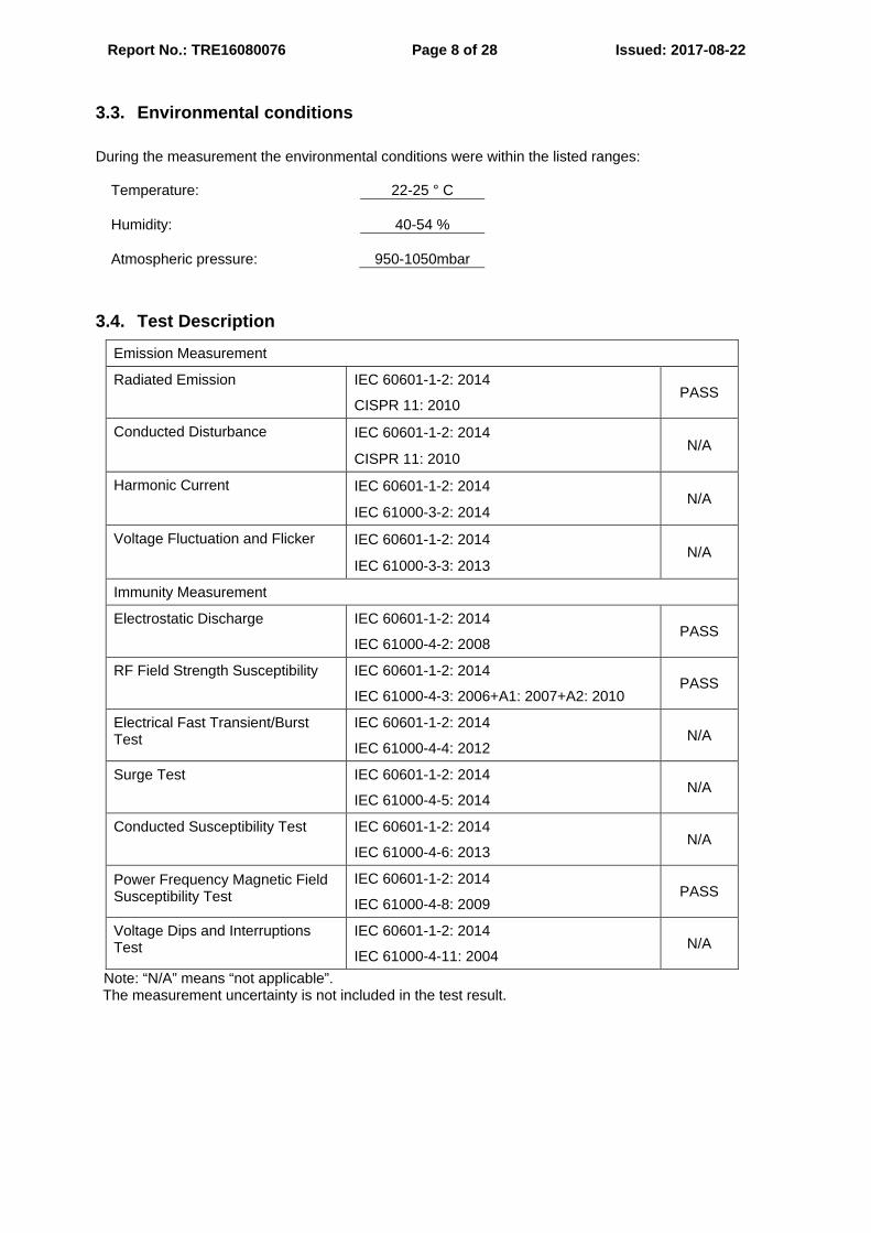
3.3. Environmental conditions During the measurement the environmental conditions were within the listed ranges:
Temperature: 22-25 ° C Humidity: 40-54 % Atmospheric pressure: 950-1050mbar
3.4. Test Description
Emission Measurement
Radiated Emission IEC 60601-1-2: 2014
CISPR 11: 2010 PASS
Conducted Disturbance
IEC 60601-1-2: 2014
CISPR 11: 2010 N/A
Harmonic Current IEC 60601-1-2: 2014
IEC 61000-3-2: 2014 N/A
Voltage Fluctuation and Flicker IEC 60601-1-2: 2014
IEC 61000-3-3: 2013 N/A
Immunity Measurement
Electrostatic Discharge IEC 60601-1-2: 2014
IEC 61000-4-2: 2008 PASS
RF Field Strength Susceptibility
IEC 60601-1-2: 2014
IEC 61000-4-3: 2006+A1: 2007+A2: 2010 PASS
Electrical Fast Transient/Burst Test
IEC 60601-1-2: 2014
IEC 61000-4-4: 2012 N/A
Surge Test IEC 60601-1-2: 2014
IEC 61000-4-5: 2014 N/A
Conducted Susceptibility Test IEC 60601-1-2: 2014
IEC 61000-4-6: 2013 N/A
Power Frequency Magnetic Field Susceptibility Test
IEC 60601-1-2: 2014
IEC 61000-4-8: 2009 PASS
Voltage Dips and Interruptions Test
IEC 60601-1-2: 2014
IEC 61000-4-11: 2004 N/A
Note: “N/A” means “not applicable”. The measurement uncertainty is not included in the test result.
Report No.: TRE16080076 Page 9 of 28 Issued: 2017-08-22
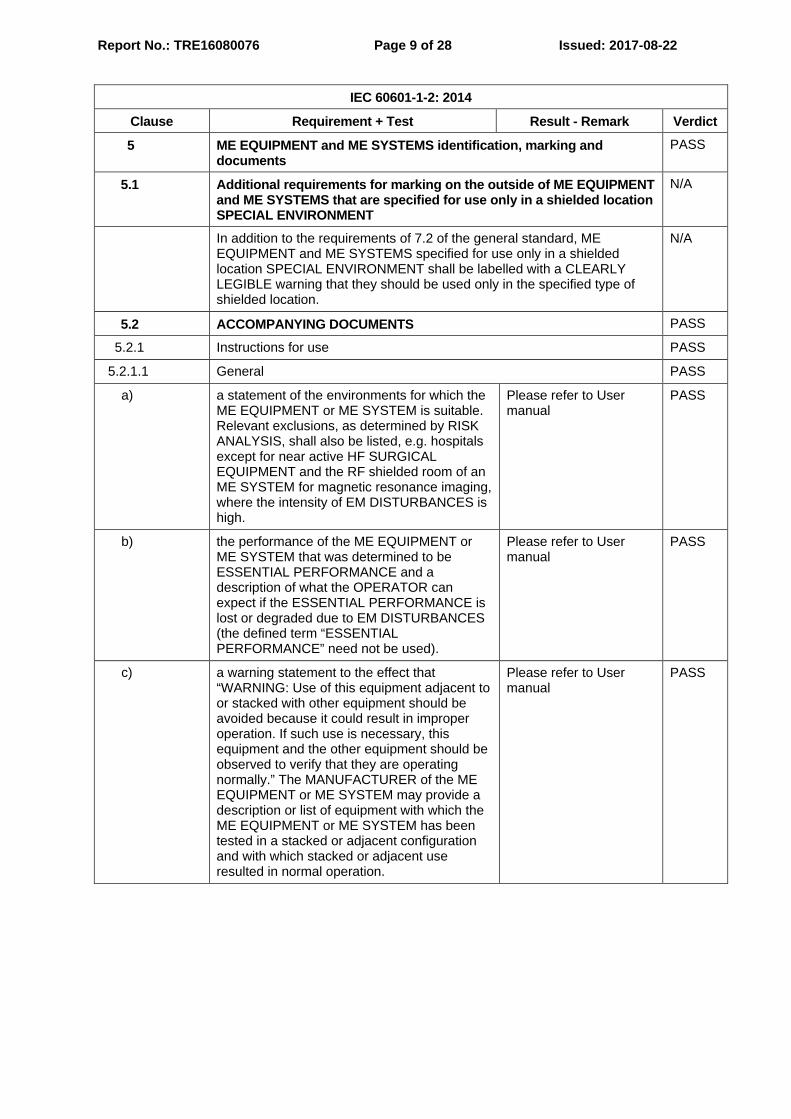
IEC 60601-1-2: 2014 Clause Requirement + Test Result - Remark Verdict 5 ME EQUIPMENT and ME SYSTEMS identification, marking and
documents PASS
5.1 Additional requirements for marking on the outside of ME EQUIPMENT and ME SYSTEMS that are specified for use only in a shielded location SPECIAL ENVIRONMENT
N/A
In addition to the requirements of 7.2 of the general standard, ME EQUIPMENT and ME SYSTEMS specified for use only in a shielded location SPECIAL ENVIRONMENT shall be labelled with a CLEARLY LEGIBLE warning that they should be used only in the specified type of shielded location.
N/A
5.2 ACCOMPANYING DOCUMENTS PASS
5.2.1 Instructions for use PASS
5.2.1.1 General PASS
a) a statement of the environments for which the ME EQUIPMENT or ME SYSTEM is suitable. Relevant exclusions, as determined by RISK ANALYSIS, shall also be listed, e.g. hospitals except for near active HF SURGICAL EQUIPMENT and the RF shielded room of an ME SYSTEM for magnetic resonance imaging, where the intensity of EM DISTURBANCES is high.
Please refer to User manual
PASS
b) the performance of the ME EQUIPMENT or ME SYSTEM that was determined to be ESSENTIAL PERFORMANCE and a description of what the OPERATOR can expect if the ESSENTIAL PERFORMANCE is lost or degraded due to EM DISTURBANCES (the defined term “ESSENTIAL PERFORMANCE” need not be used).
Please refer to User manual
PASS
c) a warning statement to the effect that “WARNING: Use of this equipment adjacent to or stacked with other equipment should be avoided because it could result in improper operation. If such use is necessary, this equipment and the other equipment should be observed to verify that they are operating normally.” The MANUFACTURER of the ME EQUIPMENT or ME SYSTEM may provide a description or list of equipment with which the ME EQUIPMENT or ME SYSTEM has been tested in a stacked or adjacent configuration and with which stacked or adjacent use resulted in normal operation.
Please refer to User manual
PASS
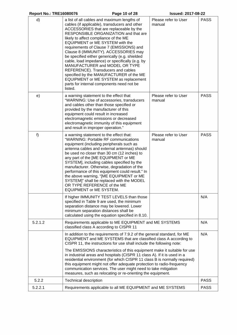
Report No.: TRE16080076 Page 10 of 28 Issued: 2017-08-22 d) a list of all cables and maximum lengths of
cables (if applicable), transducers and other ACCESSORIES that are replaceable by the RESPONSIBLE ORGANIZATION and that are likely to affect compliance of the ME EQUIPMENT or ME SYSTEM with the requirements of Clause 7 (EMISSIONS) and Clause 8 (IMMUNITY). ACCESSORIES may be specified either generically (e.g. shielded cable, load impedance) or specifically (e.g. by MANUFACTURER and MODEL OR TYPE REFERENCE). Transducers and cables specified by the MANUFACTURER of the ME EQUIPMENT or ME SYSTEM as replacement parts for internal components need not be listed.
Please refer to User manual
PASS
e) a warning statement to the effect that “WARNING: Use of accessories, transducers and cables other than those specified or provided by the manufacturer of this equipment could result in increased electromagnetic emissions or decreased electromagnetic immunity of this equipment and result in improper operation.”
Please refer to User manual
PASS
f) a warning statement to the effect that: “WARNING: Portable RF communications equipment (including peripherals such as antenna cables and external antennas) should be used no closer than 30 cm (12 inches) to any part of the [ME EQUIPMENT or ME SYSTEM], including cables specified by the manufacturer. Otherwise, degradation of the performance of this equipment could result.” In the above warning, “[ME EQUIPMENT or ME SYSTEM]” shall be replaced with the MODEL OR TYPE REFERENCE of the ME EQUIPMENT or ME SYSTEM.
Please refer to User manual
PASS
If higher IMMUNITY TEST LEVELS than those specified in Table 9 are used, the minimum separation distance may be lowered. Lower minimum separation distances shall be calculated using the equation specified in 8.10.
N/A
5.2.1.2 Requirements applicable to ME EQUIPMENT and ME SYSTEMS classified class A according to CISPR 11
N/A
In addition to the requirements of 7.9.2 of the general standard, for ME EQUIPMENT and ME SYSTEMS that are classified class A according to CISPR 11, the instructions for use shall include the following note:
The EMISSIONS characteristics of this equipment make it suitable for use in industrial areas and hospitals (CISPR 11 class A). If it is used in a residential environment (for which CISPR 11 class B is normally required) this equipment might not offer adequate protection to radio-frequency communication services. The user might need to take mitigation measures, such as relocating or re-orienting the equipment.
N/A
5.2.2 Technical description PASS
5.2.2.1 Requirements applicable to all ME EQUIPMENT and ME SYSTEMS PASS
Report No.: TRE16080076 Page 11 of 28 Issued: 2017-08-22
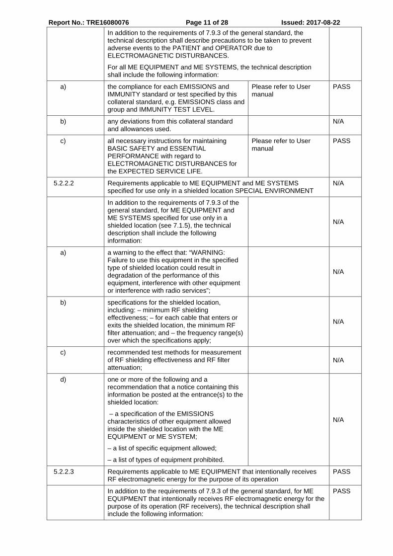
In addition to the requirements of 7.9.3 of the general standard, the technical description shall describe precautions to be taken to prevent adverse events to the PATIENT and OPERATOR due to ELECTROMAGNETIC DISTURBANCES.
For all ME EQUIPMENT and ME SYSTEMS, the technical description shall include the following information:
a) the compliance for each EMISSIONS and IMMUNITY standard or test specified by this collateral standard, e.g. EMISSIONS class and group and IMMUNITY TEST LEVEL.
Please refer to User manual
PASS
b) any deviations from this collateral standard and allowances used.
N/A
c) all necessary instructions for maintaining BASIC SAFETY and ESSENTIAL PERFORMANCE with regard to ELECTROMAGNETIC DISTURBANCES for the EXPECTED SERVICE LIFE.
Please refer to User manual
PASS
5.2.2.2 Requirements applicable to ME EQUIPMENT and ME SYSTEMS specified for use only in a shielded location SPECIAL ENVIRONMENT
N/A
In addition to the requirements of 7.9.3 of the general standard, for ME EQUIPMENT and ME SYSTEMS specified for use only in a shielded location (see 7.1.5), the technical description shall include the following information:
N/A
a) a warning to the effect that: “WARNING: Failure to use this equipment in the specified type of shielded location could result in degradation of the performance of this equipment, interference with other equipment or interference with radio services”;
N/A
b) specifications for the shielded location, including: – minimum RF shielding effectiveness; – for each cable that enters or exits the shielded location, the minimum RF filter attenuation; and – the frequency range(s) over which the specifications apply;
N/A
c) recommended test methods for measurement of RF shielding effectiveness and RF filter attenuation;
N/A
d) one or more of the following and a recommendation that a notice containing this information be posted at the entrance(s) to the shielded location:
– a specification of the EMISSIONS characteristics of other equipment allowed inside the shielded location with the ME EQUIPMENT or ME SYSTEM;
– a list of specific equipment allowed;
– a list of types of equipment prohibited.
N/A
5.2.2.3 Requirements applicable to ME EQUIPMENT that intentionally receives RF electromagnetic energy for the purpose of its operation
PASS
In addition to the requirements of 7.9.3 of the general standard, for ME EQUIPMENT that intentionally receives RF electromagnetic energy for the purpose of its operation (RF receivers), the technical description shall include the following information:
PASS
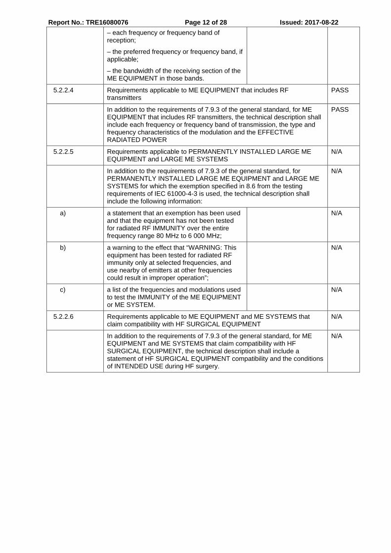
Report No.: TRE16080076 Page 12 of 28 Issued: 2017-08-22 – each frequency or frequency band of
reception;
– the preferred frequency or frequency band, if applicable;
– the bandwidth of the receiving section of the ME EQUIPMENT in those bands.
5.2.2.4 Requirements applicable to ME EQUIPMENT that includes RF transmitters
PASS
In addition to the requirements of 7.9.3 of the general standard, for ME EQUIPMENT that includes RF transmitters, the technical description shall include each frequency or frequency band of transmission, the type and frequency characteristics of the modulation and the EFFECTIVE RADIATED POWER
PASS
5.2.2.5 Requirements applicable to PERMANENTLY INSTALLED LARGE ME EQUIPMENT and LARGE ME SYSTEMS
N/A
In addition to the requirements of 7.9.3 of the general standard, for PERMANENTLY INSTALLED LARGE ME EQUIPMENT and LARGE ME SYSTEMS for which the exemption specified in 8.6 from the testing requirements of IEC 61000-4-3 is used, the technical description shall include the following information:
N/A
a) a statement that an exemption has been used and that the equipment has not been tested for radiated RF IMMUNITY over the entire frequency range 80 MHz to 6 000 MHz;
N/A
b) a warning to the effect that “WARNING: This equipment has been tested for radiated RF immunity only at selected frequencies, and use nearby of emitters at other frequencies could result in improper operation”;
N/A
c) a list of the frequencies and modulations used to test the IMMUNITY of the ME EQUIPMENT or ME SYSTEM.
N/A
5.2.2.6 Requirements applicable to ME EQUIPMENT and ME SYSTEMS that claim compatibility with HF SURGICAL EQUIPMENT
N/A
In addition to the requirements of 7.9.3 of the general standard, for ME EQUIPMENT and ME SYSTEMS that claim compatibility with HF SURGICAL EQUIPMENT, the technical description shall include a statement of HF SURGICAL EQUIPMENT compatibility and the conditions of INTENDED USE during HF surgery.
N/A
Report No.: TRE16080076 Page 13 of 28 Issued: 2017-08-22
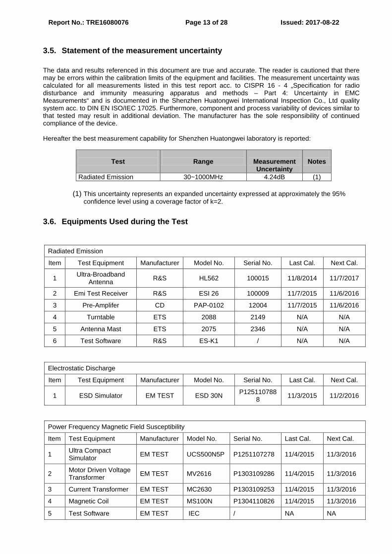
3.5. Statement of the measurement uncertainty The data and results referenced in this document are true and accurate. The reader is cautioned that there may be errors within the calibration limits of the equipment and facilities. The measurement uncertainty was calculated for all measurements listed in this test report acc. to CISPR 16 - 4 „Specification for radio disturbance and immunity measuring apparatus and methods – Part 4: Uncertainty in EMC Measurements“ and is documented in the Shenzhen Huatongwei International Inspection Co., Ltd quality system acc. to DIN EN ISO/IEC 17025. Furthermore, component and process variability of devices similar to that tested may result in additional deviation. The manufacturer has the sole responsibility of continued compliance of the device. Hereafter the best measurement capability for Shenzhen Huatongwei laboratory is reported:
Test
Range
Measurement Uncertainty
Notes
Radiated Emission 30~1000MHz 4.24dB (1)
(1) This uncertainty represents an expanded uncertainty expressed at approximately the 95% confidence level using a coverage factor of k=2.
3.6. Equipments Used during the Test
Radiated Emission
Item Test Equipment Manufacturer Model No. Serial No. Last Cal. Next Cal.
1 Ultra-Broadband Antenna R&S HL562 100015 11/8/2014 11/7/2017
2 Emi Test Receiver R&S ESI 26 100009 11/7/2015 11/6/2016
3 Pre-Amplifer CD PAP-0102 12004 11/7/2015 11/6/2016
4 Turntable ETS 2088 2149 N/A N/A
5 Antenna Mast ETS 2075 2346 N/A N/A
6 Test Software R&S ES-K1 / N/A N/A
Electrostatic Discharge
Item Test Equipment Manufacturer Model No. Serial No. Last Cal. Next Cal.
1 ESD Simulator EM TEST ESD 30N P1251107888 11/3/2015 11/2/2016
Power Frequency Magnetic Field Susceptibility
Item Test Equipment Manufacturer Model No. Serial No. Last Cal. Next Cal.
1 Ultra Compact Simulator EM TEST UCS500N5P P1251107278 11/4/2015 11/3/2016
2 Motor Driven Voltage Transformer EM TEST MV2616 P1303109286 11/4/2015 11/3/2016
3 Current Transformer EM TEST MC2630 P1303109253 11/4/2015 11/3/2016
4 Magnetic Coil EM TEST MS100N P1304110826 11/4/2015 11/3/2016
5 Test Software EM TEST IEC / NA NA
Report No.: TRE16080076 Page 14 of 28 Issued: 2017-08-22
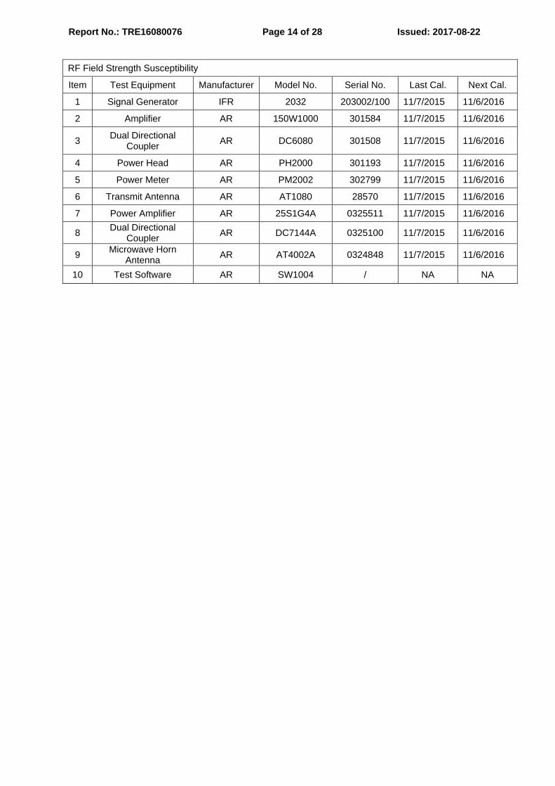
RF Field Strength Susceptibility
Item Test Equipment Manufacturer Model No. Serial No. Last Cal. Next Cal.
1 Signal Generator IFR 2032 203002/100 11/7/2015 11/6/2016
2 Amplifier AR 150W1000 301584 11/7/2015 11/6/2016
3 Dual Directional Coupler AR DC6080 301508 11/7/2015 11/6/2016
4 Power Head AR PH2000 301193 11/7/2015 11/6/2016
5 Power Meter AR PM2002 302799 11/7/2015 11/6/2016
6 Transmit Antenna AR AT1080 28570 11/7/2015 11/6/2016
7 Power Amplifier AR 25S1G4A 0325511 11/7/2015 11/6/2016
8 Dual Directional Coupler AR DC7144A 0325100 11/7/2015 11/6/2016
9 Microwave Horn Antenna AR AT4002A 0324848 11/7/2015 11/6/2016
10 Test Software AR SW1004 / NA NA
Report No.: TRE16080076 Page 15 of 28 Issued: 2017-08-22 4 . T E S T C O N D I T I O N S A N D R E S U L T S
4.1. Radiated Emission For test instruments and accessories used see section 3.6.
4.1.1. Description of the test location
Test location: Shielded room No. 6
4.1.2. Limits of disturbance (Class B)
Frequency (MHz) Distance (Meters) Field Strengths Limits (dBµV/m)
30 ~ 230 3 40
230 ~ 1000 3 47
Note: (1) The tighter limit shall apply at the edge between two frequency bands.
(2) Distance refers to the distance in meters between the test instrument antenna and the closest point of any part of the E.U.T.
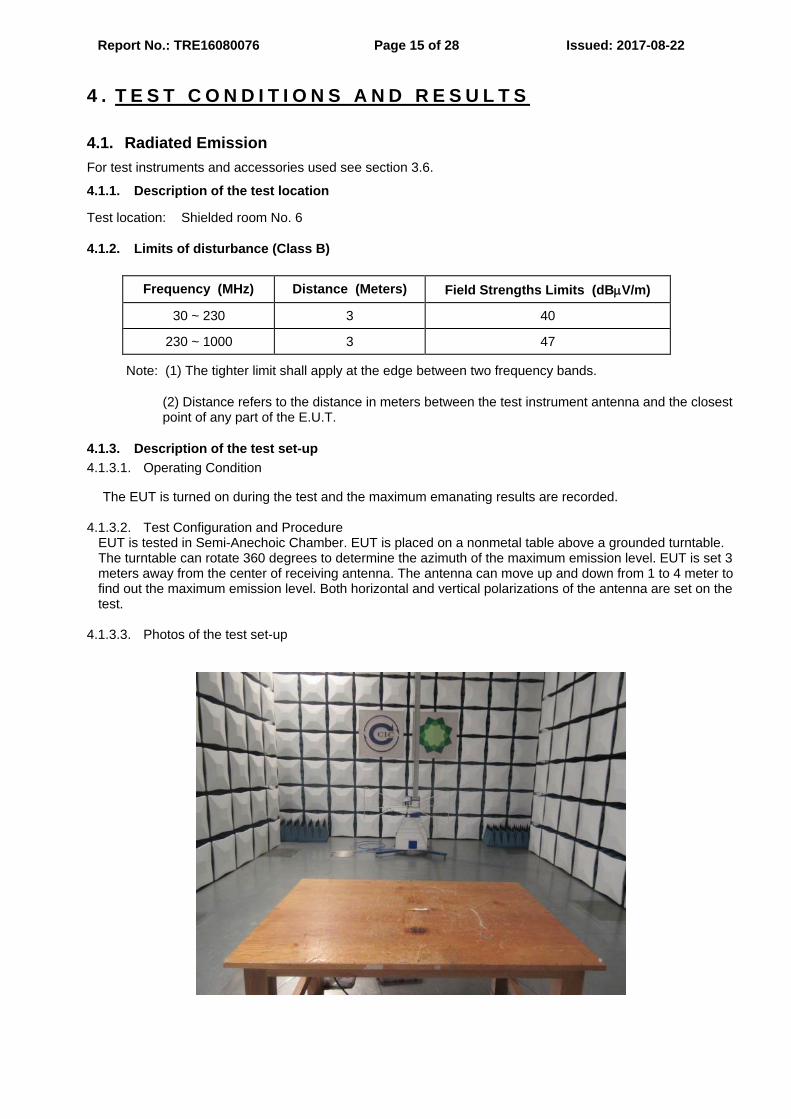
4.1.3. Description of the test set-up 4.1.3.1. Operating Condition
The EUT is turned on during the test and the maximum emanating results are recorded. 4.1.3.2. Test Configuration and Procedure
EUT is tested in Semi-Anechoic Chamber. EUT is placed on a nonmetal table above a grounded turntable. The turntable can rotate 360 degrees to determine the azimuth of the maximum emission level. EUT is set 3 meters away from the center of receiving antenna. The antenna can move up and down from 1 to 4 meter to find out the maximum emission level. Both horizontal and vertical polarizations of the antenna are set on the test.
4.1.3.3. Photos of the test set-up
Report No.: TRE16080076 Page 16 of 28 Issued: 2017-08-22
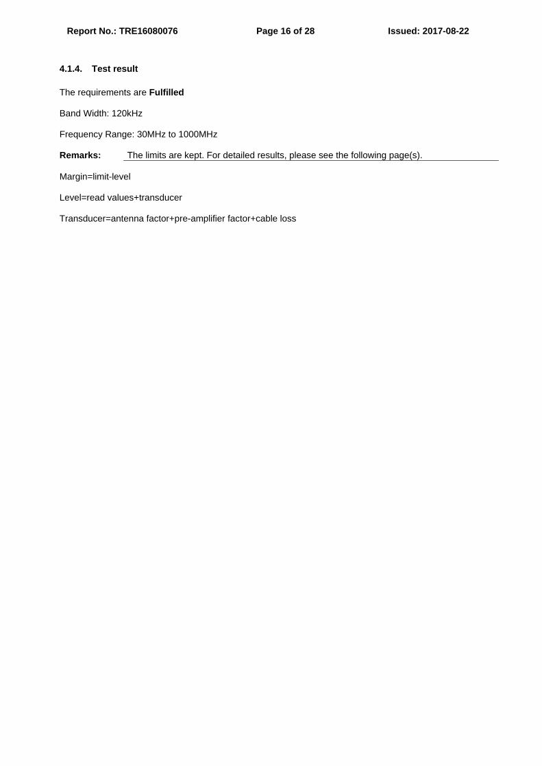
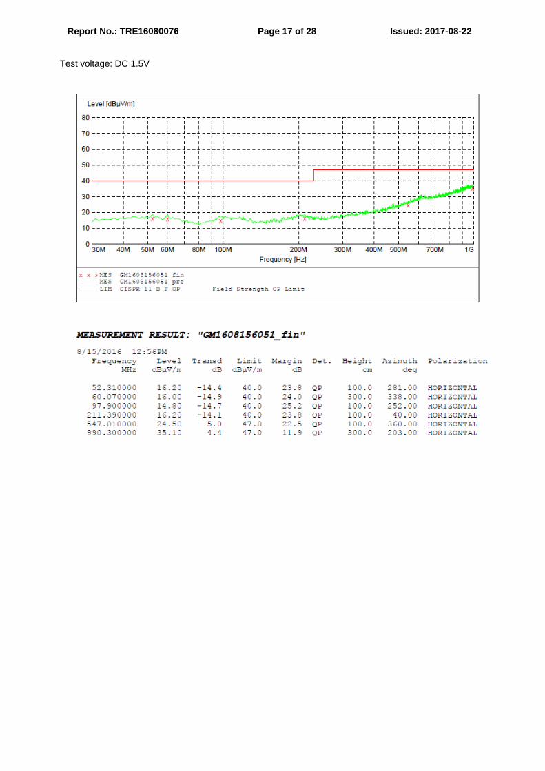
4.1.4. Test result The requirements are Fulfilled Band Width: 120kHz Frequency Range: 30MHz to 1000MHz Remarks: The limits are kept. For detailed results, please see the following page(s). Margin=limit-level Level=read values+transducer Transducer=antenna factor+pre-amplifier factor+cable loss
Report No.: TRE16080076 Page 17 of 28 Issued: 2017-08-22 Test voltage: DC 1.5V
Report No.: TRE16080076 Page 18 of 28 Issued: 2017-08-22
Report No.: TRE16080076 Page 19 of 28 Issued: 2017-08-22
4.2. Conducted disturbance The test is not applicable to the EUT. 4.3. Harmonic current The test is not applicable to the EUT.
4.4. Voltage Fluctuation and Flicker The test is not applicable to the EUT. 4.5. Electrostatic discharge For test instruments and accessories used see section 3.6.
4.5.1. Description of the test location and date Test location: Shielded room No. 8 Date of test: Aug. 17, 2017 Operator: LuoRin
4.5.2. Severity levels of electrostatic discharge
Level Test Voltage
Contact Discharge (KV) Test Voltage
Air Discharge (KV) 1 2 2
2 4 4
3 6 8
4 8 15
X Special Special Note: equipment and systems shall comply with the requirements of clause 8.9 of IEC 60601-1-2: 2014
at immunity test levels of ± 2KV, ± 4KV, ±8KV and ±15KV for air discharge and ±8KV for contact discharge.
4.5.3. Description of the test set-up 4.5.3.1. Operating Condition
The EUT is turned on during the test and the results of the maximum susceptive results are recorded.
Report No.: TRE16080076 Page 20 of 28 Issued: 2017-08-22
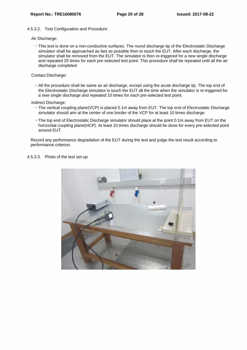
4.5.3.2. Test Configuration and Procedure:
Air Discharge:
-This test is done on a non-conductive surfaces. The round discharge tip of the Electrostatic Discharge simulator shall be approached as fast as possible then to touch the EUT. After each discharge, the simulator shall be removed from the EUT. The simulator is then re-triggered for a new single discharge and repeated 25 times for each pre-selected test point. This procedure shall be repeated until all the air discharge completed
Contact Discharge:
-All the procedure shall be same as air discharge, except using the acute discharge tip. The top end of the Electrostatic Discharge simulator is touch the EUT all the time when the simulator is re-triggered for a new single discharge and repeated 10 times for each pre-selected test point.
Indirect Discharge: -The vertical coupling plane(VCP) is placed 0.1m away from EUT. The top end of Electrostatic Discharge
simulator should aim at the center of one border of the VCP for at least 10 times discharge.
-The top end of Electrostatic Discharge simulator should place at the point 0.1m away from EUT on the horizontal coupling plane(HCP). At least 10 times discharge should be done for every pre-selected point around EUT.
Record any performance degradation of the EUT during the test and judge the test result according to performance criterion.
4.5.3.3. Photo of the test set-up
Report No.: TRE16080076 Page 21 of 28 Issued: 2017-08-22
4.5.4. Test specification: Test voltage: DC 1.5V Contact discharge voltage: 8 kV Number of discharges: 10 □ 25 Air discharge voltage: 2 kV 4 kV 8 kV 15 kV Number of discharges: 10 □ 25 Type of discharge: Direct discharge Air discharge Contact discharge Indirect discharge Contact discharge Polarity: Positive Negative Discharge location: see photo documentation of the test set-up The surface of USB port horizontal coupling plane (HCP) vertical coupling plane (VCP)
4.5.5. Test result No degradation of function. Comply with IEC 60601-1-2: 2014.

Report No.: TRE16080076 Page 22 of 28 Issued: 2017-08-22
4.6. Radiated, radio-frequency, electromagnetic field For test instruments and accessories used see section 3.6.
4.6.1. Description of the test location and date Test location: Shielded room No. 7 Date of test: Aug. 16, 2017 Operator: LuoRin
4.6.2. Severity levels of radiated, radio-frequency, electromagnetic field
Level Field Strength (V/m)
1. 1
2. 3
3. 10
X Special Note: equipment and systems shall comply with the requirements of clause 8.9 of IEC 60601-1-2: 2014, at
immunity test levels.
4.6.3. Description of the test set-up 4.6.3.1. Operating Condition
The EUT is turned on during the test and the results of the maximum susceptive results are recorded.
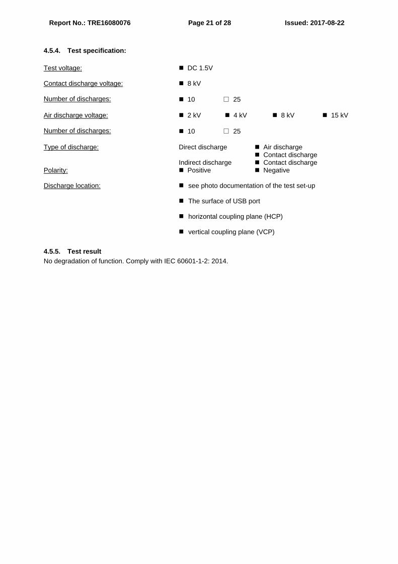
4.6.3.2. Test Procedure EUT and its auxiliary instrument are placed on a turntable which is 0.8 meter above ground. Transmitting antenna mounted on an antenna mast is set 3 meter away from the EUT. During the test, each of the four sides of EUT will face the transmitting antenna with the turntable cycled. Both horizontal and vertical polarization of the antenna are set on test and measured individually.
In order to judge the performance of the EUT, a set of monitor system is used.
Record any performance degradation of the EUT during the test and judge the test result according to performance criterion.
Report No.: TRE16080076 Page 23 of 28 Issued: 2017-08-22
4.6.3.3. Photo of the test set-up
4.6.4. Test specification: Test voltage: DC 1.5V Frequency range: 80 MHz to 2700 MHz Field strength: 10 V/m EUT - antenna separation: 3 m Modulation: AM: 80 %
sinusoidal 1k Hz Frequency step: 1 % with 3 s dwell time Antenna polarisation: horizontal vertical
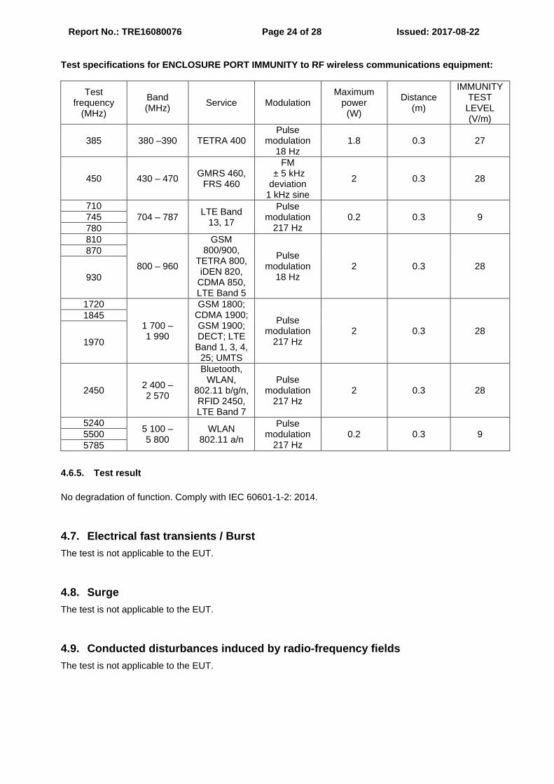
Report No.: TRE16080076 Page 24 of 28 Issued: 2017-08-22 Test specifications for ENCLOSURE PORT IMMUNITY to RF wireless communications equipment:
Test frequency
(MHz)
Band (MHz) Service Modulation
Maximum power
(W)
Distance (m)
IMMUNITY TEST
LEVEL (V/m)
385 380 –390 TETRA 400 Pulse
modulation 18 Hz
1.8 0.3 27
450 430 – 470 GMRS 460, FRS 460
FM ± 5 kHz deviation
1 kHz sine
2 0.3 28
710 704 – 787 LTE Band
13, 17
Pulse modulation
217 Hz 0.2 0.3 9 745
780 810
800 – 960
GSM 800/900,
TETRA 800, iDEN 820,
CDMA 850, LTE Band 5
Pulse modulation
18 Hz 2 0.3 28
870
930
1720
1 700 – 1 990
GSM 1800; CDMA 1900; GSM 1900; DECT; LTE Band 1, 3, 4,
25; UMTS
Pulse modulation
217 Hz 2 0.3 28
1845
1970
2450 2 400 – 2 570
Bluetooth, WLAN,
802.11 b/g/n, RFID 2450, LTE Band 7
Pulse modulation
217 Hz 2 0.3 28
5240 5 100 – 5 800
WLAN 802.11 a/n
Pulse modulation
217 Hz 0.2 0.3 9 5500
5785
4.6.5. Test result No degradation of function. Comply with IEC 60601-1-2: 2014.
4.7. Electrical fast transients / Burst The test is not applicable to the EUT.
4.8. Surge The test is not applicable to the EUT.
4.9. Conducted disturbances induced by radio-frequency fields The test is not applicable to the EUT.
Report No.: TRE16080076 Page 25 of 28 Issued: 2017-08-22
4.10. Magnetic Field Immunity For test instruments and accessories used see section 3.6.
4.10.1. Description of the test location and date Test location: Shielded room No. 8 Date of test: Aug. 16, 2017 Operator: LuoRin
4.10.2. Severity levels of magnetic field immunity
Level Magnetic Field Strength (A/m) 1 1
2 3
3 10
4 30
5 100
X. Special Note: equipment and systems shall comply with the requirements of 6.2.8 of clause 8.9 of IEC 60601-1-
2: 2014 at immunity test levels of 30A /m.
4.10.3. Description of the test set-up 4.10.3.1. Operating Condition
The EUT is turned on during the test, and the results of the maximum susceptive results are recorded. 4.10.3.2. Test Configuration and Procedure:
EUT is placed on an insulating support of 0.1m high above a table of 0.8m high. There is a minimum 1m*1m ground metallic plane put on this table. EUT is put in the center of the magnetic coil then three orientations of the magnetic coil, X, Y and Z, shall be rotated in order to expose the EUT to the difference polarization magnetic field.
Record any performance degradation of the EUT during the test and judge the test result according to performance criterion.
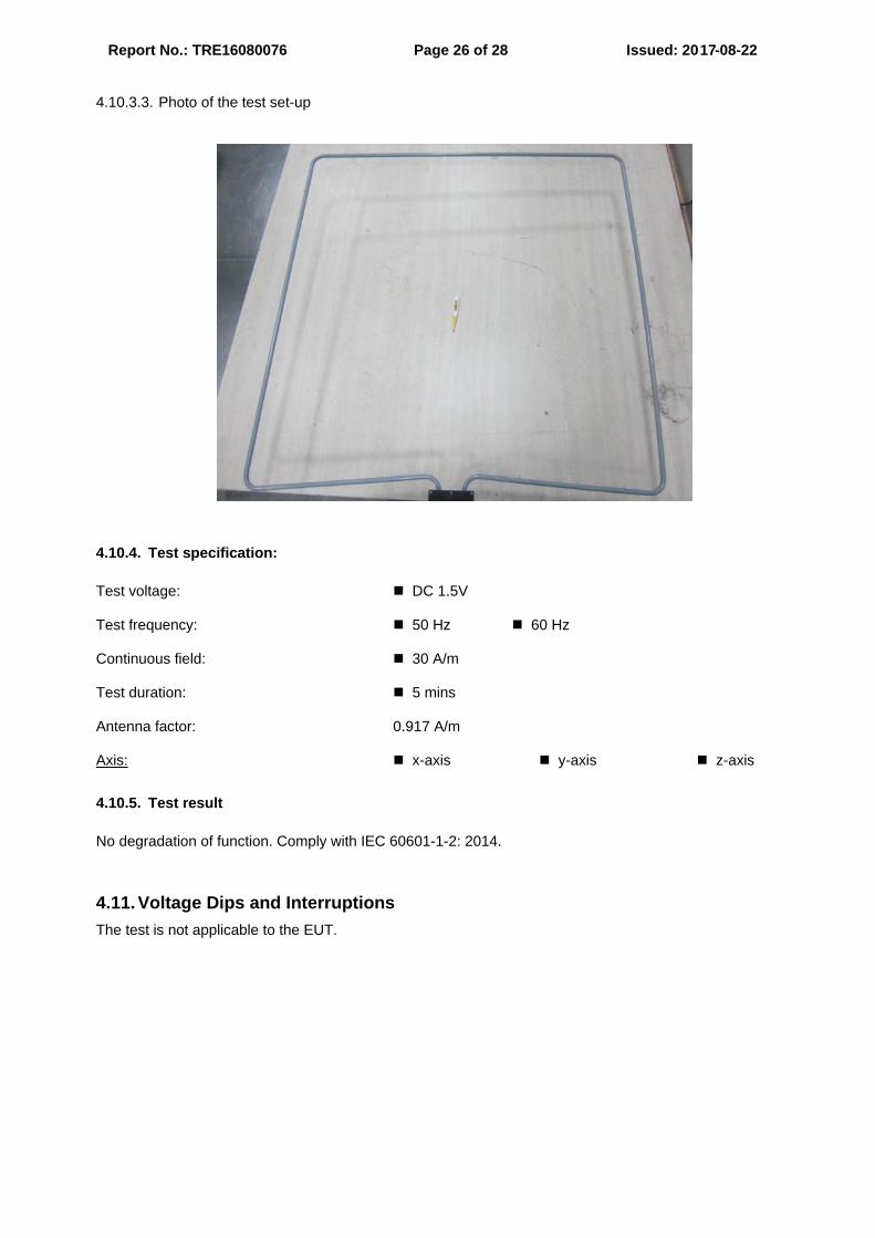
Report No.: TRE16080076 Page 26 of 28 Issued: 2017-08-22 4.10.3.3. Photo of the test set-up
4.10.4. Test specification: Test voltage: DC 1.5V Test frequency: 50 Hz 60 Hz Continuous field: 30 A/m Test duration: 5 mins Antenna factor: 0.917 A/m Axis: x-axis y-axis z-axis
4.10.5. Test result No degradation of function. Comply with IEC 60601-1-2: 2014.
4.11. Voltage Dips and Interruptions The test is not applicable to the EUT.
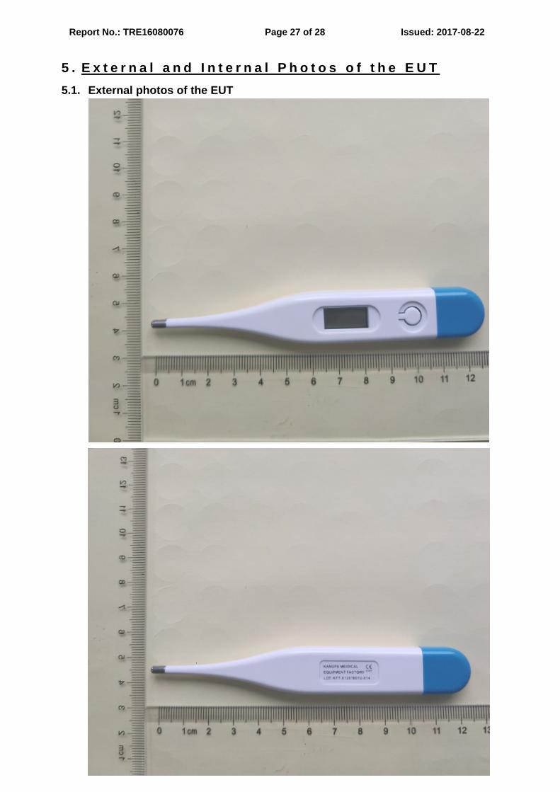
Report No.: TRE16080076 Page 27 of 28 Issued: 2017-08-22 5 . E x t e r n a l a n d I n t e r n a l P h o t o s o f t h e E U T 5.1. External photos of the EUT
Report No.: TRE16080076 Page 28 of 28 Issued: 2017-08-22
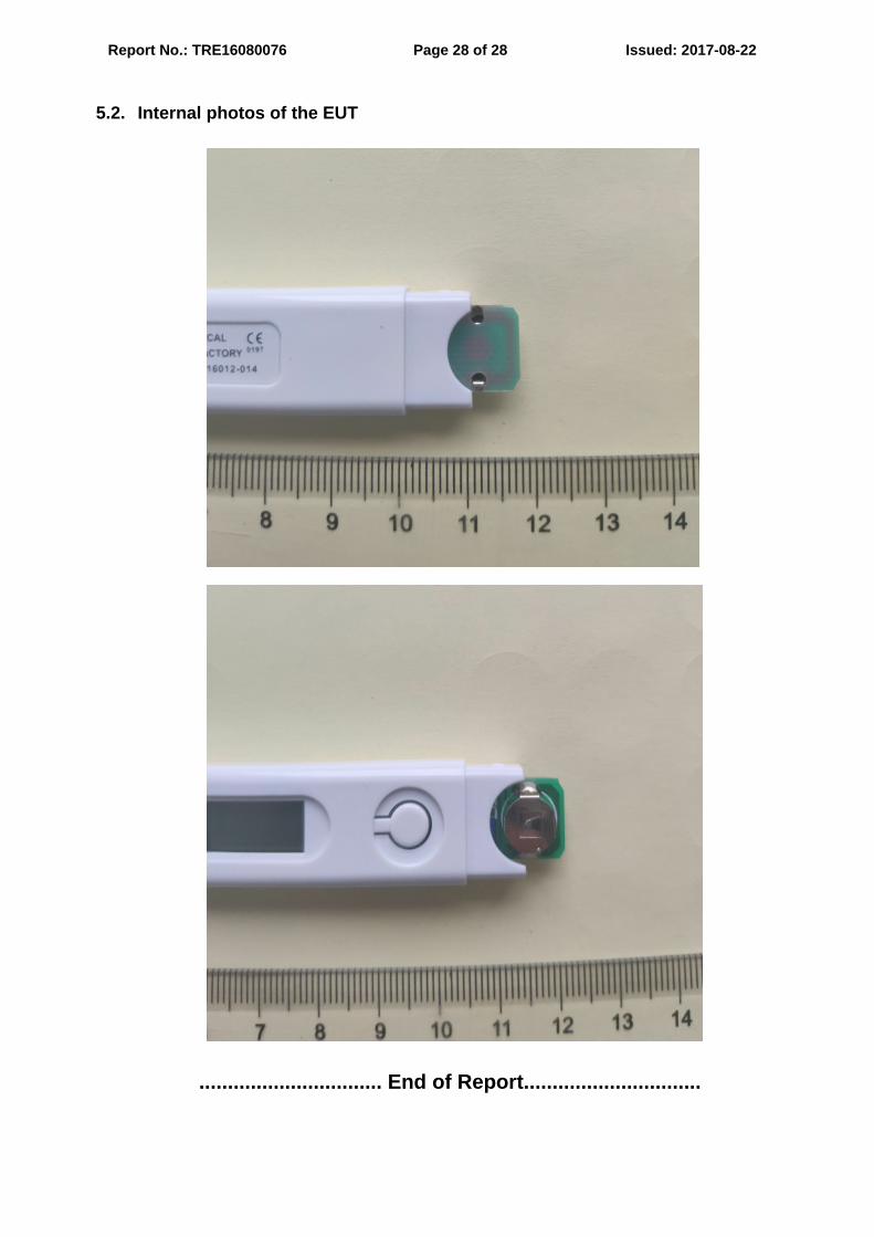
5.2. Internal photos of the EUT
................................ End of Report...............................