TRANSPORTATION RESEARCH RECORD 1089 11 The …onlinepubs.trb.org › Onlinepubs › trr › 1986 ›...
6
TRANSPORTATION RESEARCH RECORD 1089 11 The Pressuremeter in Geotechnical Practice ERNEST WINTER The pressuremeter, Introduced In its present form In the 1950s, has gained substantial acceptance In the United States. Typical testing procedures have for the most part not changed since the meter's Introduction, but changes are being recommended by researchers to accommodate test evaluations in clay soils. The test procedure ls In the process of being standardized. Typical uses of the test for foundation design, settlement anal- ysis, and pile behavior are reviewed. The pressuremeter as an in situ testing instrument is well known and used in the United States and is widely accepted for use in routine investigations. Since its introduction, consider- able research and development have occurred and new testing methods as well as new methods of evaluation have been suggested. It is accordingly considered appropriate to trace this development from its beginning for a better overall understand- ing of the test of today. ORIGINS OF PRESSUREMETER TEST The modem use of the pressuremeter is based on the efforts of Louis Menard, a French engineer, who developed the original concept by Kogler into a usable test instrument in the late 1950s. Menard also recognized, however, that new empirical methods will be required to analyze foundation performance with the pressuremeter and made considerable full-scale mea- surements to support his empirical correlations. At the introduction of the pressuremeter in the United States, the instrument was furnished with a whole set of new rules based on Menard's measurements and evaluations. These eval- uation methods were mostly unknown to the engineering com- munity. The question was whether those rules would be accepted for the design or whether additional research would be necessary to produce parameters for the Menard rules for local conditions and on correlation of the test results with known geotechnical parameters. The first category of efforts was generally pursued by consulting engineers, whereas cor- relations with shear parameters and compressibility were developed mostly by researchers. After more than 20 years of use, a great number of test results are available and typical test values in particular geologic formations are known. The results of disturbance during installation are relatively well established, and experi- ence has shown that the forming of the borehole has a signifi- cant effect on the regular pressuremeter test. Efforts to stan- dardize the procedures of installation as well as the test have Schnabel Engineering Associates, 4909 Cordell Avenue, Bethesda, Md . 20814. led to a new ASTM standard to be introduced in the near future. The pressuremeter test consists of the expansion of a mem- brane, usually in a predrilled borehole (Figure 1). The volume change and the pressure are measured in the test, and the pressures to increase the volume are generally applied in pre- determined steps. A modulus is then determined to reflect the relation between volume change and pressure, and the pressure at which failure of the soil occurs is also evaluated. It is these two parameters, the pressuremeter modulus and limit pressure, that are used in evaluations, together with the curve of pressure versus volume. PROBE / GUARD CELL flEASURING CELL GUARD CELL FIGURE 1 Schematic section of pressuremeter. The performance of the test as well as methods of evaluation will be discussed in some detail in this paper; in addition some particularly well-suited and well-developed applications for the engineering design will be reviewed. The subject of this paper is the pressuremeter as an instrument in the everyday use of geotechnical engineering. With this in mind, the single most important factor affecting the quality of the tests, namely, the preparation of the borehole, is examined in some detail. HOLE PREPARATION Two types of disturbance occur when a borehole is drilled for the test. The first type is the result of opening the hole itself. As the borehole is drilled, a stress release occurs when material is removed from the boring. This stress release is restored during the test or reduced by performing the test as soon as possible
Transcript of TRANSPORTATION RESEARCH RECORD 1089 11 The …onlinepubs.trb.org › Onlinepubs › trr › 1986 ›...

TRANSPORTATION RESEARCH RECORD 1089 11
The Pressuremeter in Geotechnical Practice ERNEST WINTER
The pressuremeter, Introduced In its present form In the 1950s, has gained substantial acceptance In the United States. Typical testing procedures have for the most part not changed since the meter's Introduction, but changes are being recommended by researchers to accommodate test evaluations in clay soils. The test procedure ls In the process of being standardized. Typical uses of the test for foundation design, settlement analysis, and pile behavior are reviewed.
The pressuremeter as an in situ testing instrument is well known and used in the United States and is widely accepted for use in routine investigations. Since its introduction, considerable research and development have occurred and new testing methods as well as new methods of evaluation have been suggested. It is accordingly considered appropriate to trace this development from its beginning for a better overall understanding of the test of today.
ORIGINS OF PRESSUREMETER TEST
The modem use of the pressuremeter is based on the efforts of Louis Menard, a French engineer, who developed the original concept by Kogler into a usable test instrument in the late 1950s. Menard also recognized, however, that new empirical methods will be required to analyze foundation performance with the pressuremeter and made considerable full-scale measurements to support his empirical correlations.
At the introduction of the pressuremeter in the United States, the instrument was furnished with a whole set of new rules based on Menard's measurements and evaluations. These evaluation methods were mostly unknown to the engineering community. The question was whether those rules would be accepted for the design or whether additional research would be necessary to produce parameters for the Menard rules for local conditions and on correlation of the test results with known geotechnical parameters. The first category of efforts was generally pursued by consulting engineers, whereas correlations with shear parameters and compressibility were developed mostly by researchers.
After more than 20 years of use, a great number of test results are available and typical test values in particular geologic formations are known. The results of disturbance during installation are relatively well established, and experience has shown that the forming of the borehole has a significant effect on the regular pressuremeter test. Efforts to standardize the procedures of installation as well as the test have
Schnabel Engineering Associates, 4909 Cordell Avenue, Bethesda, Md. 20814.
led to a new ASTM standard to be introduced in the near future.
The pressuremeter test consists of the expansion of a membrane, usually in a predrilled borehole (Figure 1). The volume change and the pressure are measured in the test, and the pressures to increase the volume are generally applied in predetermined steps. A modulus is then determined to reflect the relation between volume change and pressure, and the pressure at which failure of the soil occurs is also evaluated. It is these two parameters, the pressuremeter modulus and limit pressure, that are used in evaluations, together with the curve of pressure versus volume.
PROBE
/
GUARD CELL
flEASURING CELL
GUARD CELL
FIGURE 1 Schematic section of pressuremeter.
The performance of the test as well as methods of evaluation will be discussed in some detail in this paper; in addition some particularly well-suited and well-developed applications for the engineering design will be reviewed. The subject of this paper is the pressuremeter as an instrument in the everyday use of geotechnical engineering. With this in mind, the single most important factor affecting the quality of the tests, namely, the preparation of the borehole, is examined in some detail.
HOLE PREPARATION
Two types of disturbance occur when a borehole is drilled for the test. The first type is the result of opening the hole itself. As the borehole is drilled, a stress release occurs when material is removed from the boring. This stress release is restored during the test or reduced by performing the test as soon as possible

12
after drilling. The effect of this unload-load cycle will, however, exist as long as predrilling is part of the testing. An improvement is the self-boring pressuremeter, which is inserted while the original in situ stresses are maintained. This is still considered a research tool or special testing equipment and is used mostly on larger, elaborate projects in which the higher cost of such testing can be absorbed.
The second type of disturbance is caused by the drilling equipment along the walls of the borehole and can be considerably reduced by the use of the right tools and techniques. In everyday practice, some methods have been developed that are more useful in one soil than in others. Techniques vary by geography and country of origin. A tabulation has been assembled by ASTM for the upcoming standard, showing methods suited for particular subsoil conditions (Table I). As can be readily seen, the most widely applicable method is hand augering, which causes probably the least disturbance in most soils. The soils representing the largest problems in hole preparation are the sands and gravels, especially below ground water level. In these soils good results were obtained, however, by using mud to keep the boring open.
Another factor, also related to preparation of boreholes and disturbance, is the range of tolerances to be maintained to obtain a good test. The pressuremeter generally requires a hole in which only minimal space is maintained between the probe and the walls of the borehole in order to keep the necessary
TRANSPORTATION RESEARCH RECORD 1089
expansion of the probe to the minimum. Generally a hole diameter between 3 to 20 percent larger than that of the probe should be maintained.
THE PRESSUREMETER TEST
The test itself consists of expanding a probe in a predrilled borehole and measuring volumes and corresponding pressures. The most commonly used method is to increase pressures in about 10 increments to failure. It has also been acceptable to run the test by controlling strain and measuring the corresponding stress. The principle of the test is, however, to perform the test in a relatively short period of time, thereby measuring basically undrained conditions, even where pore-pressure dissipation is significant. Because the test results are sensitive to the speed of testing, specifically in fine-grained soils, this makes standardization more important. It has been the practice of the engineering community to perform tests according to the original recommendations of Menard in order to maintain the comparative value of the results.
As part of the testing procedure, the drill hole is advanced to the test level and cleaned of debris and cuttings. Before the probe is placed in the hole, all calibrations are completed and checked. The probe is then lowered to the test depth and pressures are applied in predetermined steps. The load incre-
TADLE 1 GUIDELINES FOR SELECTION OF BOREHOLE PREPARATION METHODS AND TOOLS
Preparation Method
Rotary drilling with bottom discharge of prepared mud
Pushed thin wall sampler
Pilot-hole drilling With subsequent
sampler pushing With simultaneous
shaving Continuous flight
auger Hand auger
In the dry With bottom
discharge of prepared mud
Driven or vibrodriven sampler
Core barrel drilling
Rotary percussion Driven, vibro-driven,
or pushed slotted tube
Carey
Soft
2
2
NR
NR
NR
NR NR
NR
Firm-Stiff
2
2
NR
NR NR
NR
Stiff-Hard
l
2
lb
NA
NA
NA
2b lb
NR
Silty
Above GWL
lb
2b
2
2b
2
2
NR NR
NR
Below GWL
NR
NR
NR
NR
NR
NR NR
NR
Sandy Loose
Above GWL
NR
NR
2
2
2
2
NR NA
NR
Below GWL
NR
NR
2
NR
NR
NR
NR NA
NR
Note: GWL = gl'Oundwatcr level; NR = not recommended; NA = not applicable; 1 = !mt choice; 2 = second choice.
"Below GWL. bMethod applicable only under certain conditions (see text). cPilot-hole drilling required beforehand.
Medium-Dense
NR
NR
2
2
NR
Sandy Gravel or Gravely
Sands a Loose Dense
2 NR
NA NA
NA NA
NA NA
NA NR
NA NA
NA NA
NR NR
2 2 NA NA
2 le
Weathered Rock
NA
NA
NA
NA
2 2
NR
WINTER
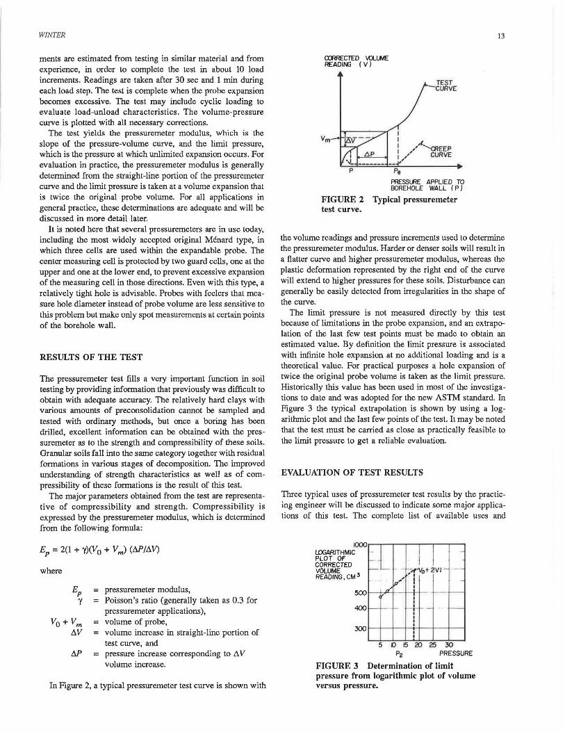
ments are estimated from testing in similar material and from experience, in order to complete the test in about 10 load increments. Readings are taken after 30 sec and 1 min during each load step. The test is complete when the probe expansion becomes excessive. The test may include cyclic loading to evaluate load-unload characteristics. The volume-pressure curve is plotted with all necessary corrections.
The test yields the pressuremeter modulus, which is the slope of the pressure-volume curve, and the limit pressure, which is the pressure at which unlimited expansion occurs. For evaluation in practice, the pressuremeter modulus is generally determined from the straight-line portion of the pressuremeter curve and the limit pressure is taken at a volume expansion that is twice the original probe volume. For all applications in general practice, these determinations are adequate and will be discussed in more detail later.
It is noted here that several pressuremeters are in use today, including the most widely accepted original Menard type, in which three cells are used within the expandable probe. The center measuring cell is protected by two guard cells, one at the upper and one at the lower end, to prevent excessive expansion of the measuring cell in those directions. Even with this type, a relatively tight hole is advisable. Probes with feelers that measure hole diameter instead of probe volume are less sensitive to this problem but make only spot measurements at certain points of the borehole wall.
RESULTS OF THE TEST
The pressuremeter test fills a very important function in soil testing by providing information that previously was difficult to obtain with adequate accuracy. The relatively hard clays with various amounts of preconsolidation cannot be sampled and tested with ordinary methods, but once a boring has been drilled, excellent information can be obtained with the pressuremeter as to the strength and compressibility of these soils. Granular soils fall into the same category together with residual formations in various stages of decomposition. The improved understanding of strength characteristics as well as of compressibility of these formations is the result of this test.
The major parameters obtained from the test are representative of compressibility and strength. Compressibility is expressed by the pressuremeter modulus, which is determined from the following formula:
where
= pressuremeter modulus, = Poisson's ratio (generally taken as 0.3 for
pressuremeter applications), = volume of probe, = volume increase in straight-line portion of
test curve, and = pressure increase corresponding to D. V
volume increase.
In Figure 2, a typical pressuremeter test curve is shown with
cmRECTED \Q..IME READING ( V)
TEST URVE
' ' 1 /"-..._CREEP : ,/ CURVE ,
Pe
PRESSLRE APPLIED TO BOREHOLE WALL ( P)
FIGURE 2 test curve.
Typical pressuremeter
13
the volume readings and pressure increments used to determine the pressuremeter modulus. Harder or denser soils will result in a flatter curve and higher pressuremeter modulus, whereas the plastic deformation represented by the right end of the curve will extend to higher pressures for these soils. Disturbance can generally be easily detected from irregularities in the shape of the curve.
The limit pressure is not measured directly by this test because of limitations in the probe expansion, and an extrapolation of the last few test points must be made to obtain an estimated value. By definition the limit pressure is associated with infinite hole expansion at no additional loading and is a theoretical value. For practical purposes a hole expansion of twice the original probe volume is taken as the limit pressure. Historically this value has been used in most of the investigations to date and was adopted for the new ASTM standard. In Figure 3 the typical extrapolation is shown by using a logarithmic plot and the last few points of the test. It may be noted that the test must be carried as close as practically feasible to the limit pressure to get a reliable evaluation.
EVALUATION OF TEST RESULTS
Three typical uses of pressuremeter test results by the practicing engineer will be discussed to indicate some major applications of this test. The complete list of available uses and
f0001...-~--...--..--~..--..----...--~
l.DGARITHMIC PLOT OF CORRECTED VOLUME READING, CM 3
5 0 15 20 25 30 P2 PRESSURE
FIGURE 3 Determination of limit pressure from logarithmic plot of volume versus pressure.

14
applications is a long one and could not be meaningfully discussed here.
Menard Rules for Evaluation
The complete design recommendations for the pressuremeter as introduced by Menard were published in Sols-Soils (1) and include design methods for several aspects of geotechnical engineering, such as spread footing foundations, pile capacity evaluations, and settlement evaluations, with no other testing required but that done with the pressuremeter. Geotechnical consultants in the United States still use pressuremeter test data in addition to conventional analysis methods when such data are available.
The basic equation for the bearing capacity of footings or caissons has been formulated as follows:
where
q 1 = ultimate bearing capacity, q0 = overburden pressure, P 1 = limit pressure from pressuremeter test, P 0 = horizontal pressure at rest, and K = bearing capacity factor varying from 0.8 to 9.
The horizontal at-rest pressure is necessary for this evaluation, which can be estimated from the pressuremeter test or can be determined by other methods.
The general formula for settlement of a foundation has been given as follows:
W = (1.33/3£) Pf..'i: + (a/4.5E) P~R
where
f..z.~ = shape coefficients, a function of the length and width of the foundation;
a = structure coefficient, generally evaluated from the ratio of pressuremeter modulus to limit pressure;
p = foundation pressure; E = pressuremeter modulus; and R = radius.
Values of these variables are given in Tables 2 and 3. Bearing capacities determined by this method are generally
TABLE 2 STRUCTURE COEFFICIENTS
Peat aal Type of Material EIP a. EIP
Overconsolidated 16 Normally consolidated 9-16 Weathered or altered 7-9
a.
1
TRANSPORTATION RESEARCH RECORD 1089
high compared with established bearing values, and settlements are generally lower than would be expected by a static settlement calculation. As an example, the typical foundation requirements of a 6- by 6-ft spread footing are examined. This footing, when founded on high-density local gravelly sand of Pleistocene origin, would be designed for a typical soil bearing pressure of 4 tsf. The pressuremeter tests performed in this geologic formation indicate limit pressures varying between 10 and 20 tsf. An evaluation of bearing capacity using the lower value and the Menard formulas will give an allowable bearing of 11,500 psf, considering normal embedments and a safety factor of 3. The settlements of this footing are calculated to be 0.6 in. when the pressuremeter modulus of 100 tsf on the low end of the range in this type of soil is used. Consideration of average parameters for this layer would result in high allowable bearing capacities that could not be realized in the design. Considering plate load test data available on this material used as a fill soil, settlements are believed to be in the realistic range. These formulas have been particularly useful in relatively hard soils or materials otherwise not suitable for sampling. A significant use has developed in estimating bearing capacities and settlements of caissons founded on good bearing materials. Allowable bearing capacities could be increased throughout the years as confidence develops based on performance of these foundations.
Static Settlement over Sand
In 1970 Schmertmann (2) published the strain distribution method to calculate settlements over sand by using the cone penetrometer. In 1978 this calculation was revised by Schmertmann (3) to include strip footings. The method gives good correlation with settlement of footings but requires the use of an elastic modulus (E), which was evaluated from cone penetrometer tests.
For users of the pressuremeter, it came as a natural application to substitute the pressuremeter modulus in the equation. It was not clear, however, what modification to the modulus, if any, would be required. Considerable field measurements were performed, and Martin (4) indicatyd in 1977 that the pressuremeter modulus, if used directly, would give reasonable correlation with field measurements in residual soils.
A number of pressuremeter tests were analyzed by the author to evaluate the correlation between the pressuremeter modulus and the modulus of deformation as used in the strain distribution method. At this time, it is believed that the ratio in residual soils is probably somewhat higher than l, and in sedimentary granular soils the modulus was found to be at least 2 to 3 times
Sand and Alluvium Sand Gravel
EIP a. EIP a. EIP a.
14 2/3 12 1/2 IO 1(3 2/3 8-14 1/2 7-12 1/3 6-10 1/4 1/2 1/2 1/3 1/4

WINTER
TABLE 3 SHAPE COEFFICIENTS FOR SETTLEMENT CALCULATIONS
L/'2R
Shape Round Square Coefficient Foundation Foundation 2 3 5
Note: L = length of foundation.
1.12 1.1
1.53 1.78 2.14 1.2 1.3 1.4
20
2.65 1.5
the pressuremeter modulus. The 6- by 6-ft footing analyzed earlier by the Menard method showed 0.8 in. settlement when this was calculated by the strain distribution method. In the sedimentary granular soils, the pressuremeter modulus is routinely used by a multiplier of 3 in these soils.
The successful use of the pressuremeter test in settlement evaluation is, however, predicated on an adequate number of tests. In many instances, the cost of adequate testing cannot be economically justified, especially in the case of smaller projects or where considerable variation in the soil profile is experienced. A logical solution appeared to be to establish a correlation with the standard penetration test that is routinely performed at frequent intervals on almost all jobs.
The evaluations were based on a great number of tests, which at first indicated no particular correlation. Then soil types were broken down by geologic origin, and correlations were attempted on that basis. Somewhat better results were obtained, and graphs (Figures 4 and 5) were developed for use with local soils.
a. w
......... ~ .,~
i
I
II I '/
'./ I
/, I 'll/IJ
/. ~ ~ I// . . . . . '. , -
,, I ' ~ D ~ o m R
'N' BLOWS I FT.
11 000
500
100
50 40 30
FIGURE 4 Correlation of pressuremeter versus standard penetration test for sedimentary granular soils.
The shaded areas indicate the possible correlation, which is relatively large and indicates that caution must be exercised. The percentage of tests covered above and below the weighted average, which is indicated by the center zero line, are also indicated. In practice the pressuremeter tests performed on a project are plotted on these sheets for each soil type and a
-!!
0 ~ ~ ~ . .
[...
/ ~,.
~ ~ ~ i;. t..
./ [...- ....
~ ~
-~ · ~
~~
-
0133)30 50
..,,,, •80 ·-40
500 400 300
200
IOO
50 40 30
'N' BLOWS I FT.
FIGURE S Correlation of pressuremeter versus standard penetration test for residual soils.
15
typical correlation is developed. This correlation is then used for estimating modulus values between tests.
Various Other Uses and Applications
One of the most acceptable applications of the pressuremeter test for geotechnical design must be the horizontal capacity evaluation of piles. The analogy is obvious, considering that the pile in horizontal loading and the pressuremeter both create pressures on cylindrical holes. After closer evaluation, however, several significant differences must be considered, such as the asymmetrical loading of the pile, friction at the perimeter and the base, and so on.
Briaud et al. (5) in a paper on laterally loaded piles considers seven known methods of evaluating the horizontal pile capacity using the pressuremeter. In the method proposed by Briaud et al., the resistance is divided into front resistance and friction resistance at the sides. The equations as proposed are as follows:
Q(front) = P(pmt) x B(pile) x S(Q)
where
Q(front)
P(pmt) B(pile)
S(Q)
=
= = =
portion of soil resistance to pile movement resulting from front reaction, force per unit length of pile; net pressuremeter-test pressure; the pile width or diameter; and shape factor= 1.0 for square piles and 0.75 for round piles.
y(pile) = y(pmt) x [R(pile)/R(pmt)]
where
y(pile) R(pile) y(pmt)
R(pmt)
= lateral deflection of pile, = pile radius, = increase in radius of soil cavity in
pressuremeter test, and = initial radius of soil cavity in pressuremeter
test.

16
F(side) = s(soil) x B(pile) x S(F)
where
F(side) = soil resistance resulting from friction, force per unit length of pile;
S(F) = shape factor= 2 for square piles and 1 for round piles; and
s(soil) = soil shear stress obtained from the pressuremeter curve by the subtangent method of Palmer (6).
The p-y curves are obtained by the addition of the Q-y curve and F-y curve at a particular depth, and a complete pile evaluation can be made. Briaud et al. report relatively good agreement with one instrumented horizontal pile load test.
In addition to the three applications included here, the pressuremeter is used in offshore engineering and many other specialty fields. It has proved to be a useful tool in testing before and after ground modification such as grouting and dynamic compaction, and considerable research work is still being done on use of the standard pressuremeter for evaluating clay soils. It may be noted that Schmertmann (7) recommends variable pressure differences between the measuring and guard cells to accommodate evaluation insensitive clays. Anderson et al. (8) in their research on the effects of creep on constant rate expansion during the pressuremeter test and on derivation of consolidation parameters from the test will consider special requirements on the speed and performance of the test.
For the engineering community using the regular pressuremeter, a standard procedure for performing the test is most important in order to obtain comparable and reproducible results. This need was recognized and a standard is under preparation at this time. The soon-to-be-issued ASTM standard
TRANSPORTA110N RESEARCH RECORD 1089
will include the recommended procedures for preparing the borehole, calibrating the equipment, performing the test, and calculating the results. The engineering applications included here as well as the great number of other design methods available for the pressuremeter have made this instrument a valuable tool in the hands of the engineer.
REFERENCES
1. L. Menard. Interpretation and Application of Pressuremeter Test Results. Sols-Soils, No. 26, 1975.
2. J. H. Schmertmann. Static Cone to Compute Static Settlement over Sand. Journal of the Soil Mechanics and Foundation Division, ASCE, Vol. 96, No. SM3, May 1970, pp. 1011-1043.
3. J. H. Schmertmann et al. Improved Strain Influence Factor Diagrams. Journal of the Geotechnical Engineering Division, ASCE, Vol. 104, No. 6T8, Aug. 1978, pp. 1131-1135.
4. R. Martin. Estimating Foundation Settlements in Residual Soils. Journal of the Geotechnical Engineering Division, ASCE, Vol. 103, No. 6T3, March 1977, pp. 197-212.
5. J. L. Briaud et al. "Laterally Loaded Piles and the Pressuremeter: Comparison of existing Methods." In Laterally Loaded Deep FoundaJions: Analysis and Performance. ASTM Special Technical Publication 835. ASTM, Philadelphia, Pa., 1985, pp. 97-111.
6. A. C. Palmer. Undrained Plane Strain Explansion of a Cylindrical Cavity in Oay: A Simple Interpretation of the Pressuremeter Test. Geotechnique, Vol. 22, 1972, pp. 451-457.
7. J. H. Schmertmann. Pressuremeter Tests in Leda Clay. Internal Report 450. Division of Building Research, National Research Council of Canada, Ottawa, Ontario, May 1979.
8. W. F. Anderson et al. "Pressuremeter Testing of Normally Consolidated Oays: The Effect of Varying Test Technique." Proc., 20th Regional Meeting of the Geological Society, University of Surrey, England, 1984, pp.21-32.
Publication of this paper sponsored by Committee on Exploration and Classification of Earth Materials.

![INDEX [onlinepubs.trb.org]onlinepubs.trb.org/Onlinepubs/trr/1977/633/633-006.pdf · 36 Figure 1. Detailed data sheet. PAVCM[NT EVALUATION FOR STATE ROUTE 016 SECl JON fHOM WOUORUFF-liORTtl-L.lMl](https://static.fdocuments.us/doc/165x107/5fc5151f4dd8c11bc64347c3/index-36-figure-1-detailed-data-sheet-pavcmnt-evaluation-for-state-route.jpg)