TRANSMISSION & DISTRIBUTION Overhead 1 Book 1/13. OVERHEAD LINE DESIGN.pdf · 1. Describe the...
26
TRAINING MANUAL 12/16/98 Overhead Line Design Training Development Centre TRANSMISSION & DISTRIBUTION
Transcript of TRANSMISSION & DISTRIBUTION Overhead 1 Book 1/13. OVERHEAD LINE DESIGN.pdf · 1. Describe the...

�T R A I N I N G
M A N U A L1 2 / 1 6 / 9 8
OverheadLine Design
Training Development Centre
TR
AN
SM
ISS
ION
&
DIS
TR
IBU
TIO
N

OO V E R H E A D L I N E
D E S I G N
OBJECTIVE:Given the Construction StandardsManual, you will be able to explain themajor components in electrical utility linedesign.
WHY?Learning line design is necessary tounderstand where electricity originates, how itis transported, and when conditions dictatethat the design must be modified or changed.
LEARNING OBJECTIVES:1. Describe the electric system from
generation to the end user.
2. Explain the types of insulators used inline design.
3. List the five factors affecting sag.
4. Explain the purpose and types ofdampers.
5. Explain the methods used to sagconductors.
6. Explain the purpose and types of systemgrounds.
PREStart Here
EMDROC UOM
ELEREV
ESR LOSPEC
PARSER
Bonding and
GroundingINT
LINFRM
CSMVEC
UGCSTK
SUR
SPL
DES
RUBCLB
CRPAMP
DEC
PTR
SMN
LADRES
HOTROP HND
CADTEN
Digger Derrick
Basic Electricity
Safety
Line Design & Construction
Tools
RUD
Copyright © 1997 by the Training and Development Centre, SaskPower. All rights reserved. 1 2 / 1 6 / 9 8
IN THIS MODULE:1. Electric System
2. Line Insulators
3. Line Conductors
4. System Grounds
RESOURCES:• Construction Standards Manual
• Lineman Information Manual, Section D
ESTIMATED TIME:2 hours
PREREQUISITES:• Construction Standards Manual module
• Electrical Sources module
LEARNING STEPS:1. Cover the manual.
2. Complete the Review Questions.
3. Clarify any questions you may have.
Copyright © 1997 by the Training and Development Centre, SaskPower. All rights reserved.1 2 / 1 6 / 9 8
Electric SystemAll electric systems start at a source called a generating station.They are usually powered by steam from coal, natural gas turbinesor hydro electric stations. Other alternatives exist and includenuclear, solar and wind powered generators.
Most of these generators produce at 15kV and 60 Hertz. Thevoltage is then stepped up through the power transformers to230kV or 138kV for transportation to a switching station. Thisstation is interconnected to others in the province by transmissionlines. This interconnection between generators, switching stationsand transmission lines is called a grid. It allows electricity to beswitched from one station to another in the event of a downed lineor disabled generating station; therefore,if one source of power iscut off, an alternate feed automatically becomes the source. Ourgrid system is also connected to other utility tie-lines, which inturn, are connected to other provinces and states.
The switching stations also direct electricity on radial lines tocustomers. Radial lines with only one feed are called distributionlines. These lines are usually stepped down to 138kV or 72kV.This is the beginning of the distribution system. These lines caneither go directly to a large industrial customer (Ipsco) or to asubstation. These substations step down the high voltage lines to alocal distribution voltage (usually 25kV) by using powertransformers. Since these lines “feed” or distribute the electricityto customers, they are called feeders. Lines that come off theselines are called “taps”.
The voltage is further lowered to secondary voltages usingdistribution transformers. This voltage (120/240 is common) isdelivered from secondary lines or services, and supply electricityto its final destination, houses and businesses.
You may wonder why electricity is stepped up to high voltages,only to be stepped down again later. When electricity has to betransmitted a long distance, a high voltage and low current is usedto minimize line losses. Alternately, a large current and low voltageis safer to use in towns because insulation and clearances can bereduced. The power loss is not considerable because the lines areshort.
4 T R A I N I N G M A N U A L .
1 2 / 1 6 / 9 8Copyright © 1997 by the Training and Development Centre, SaskPower. All rights reserved.
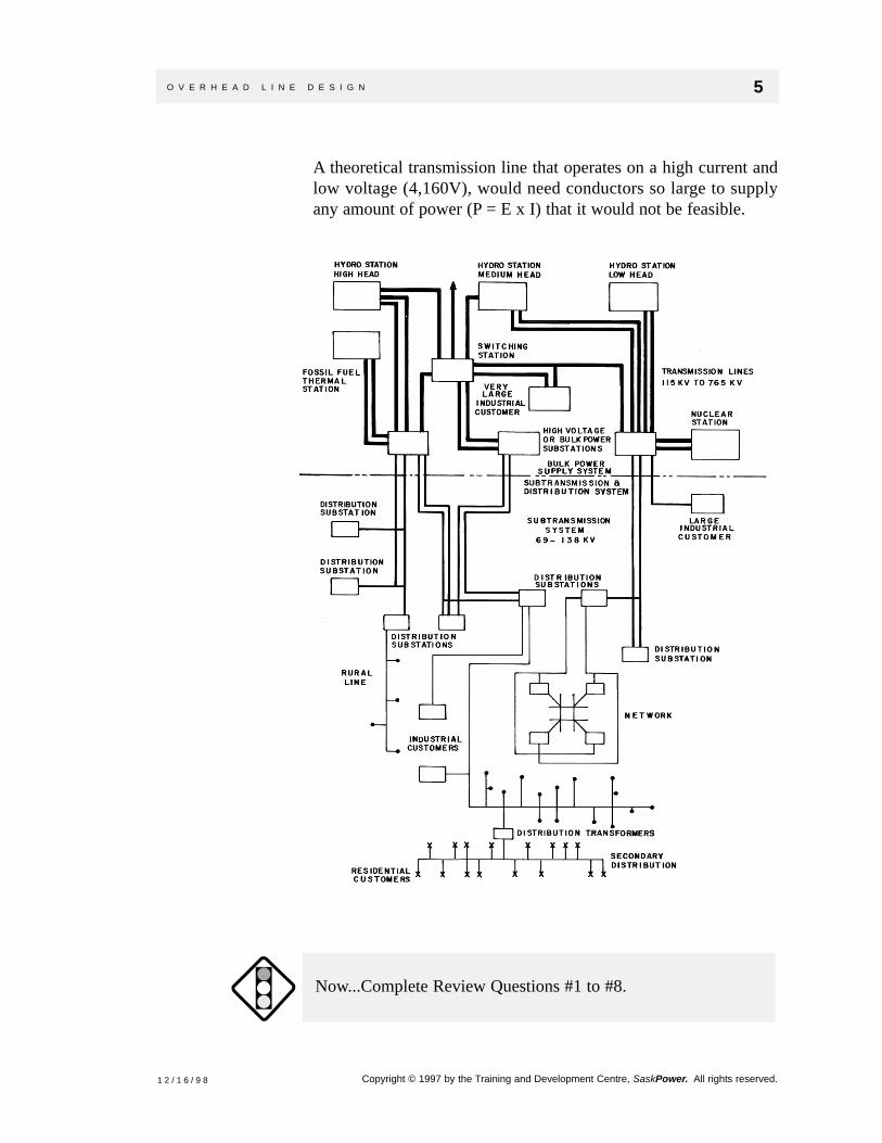
A theoretical transmission line that operates on a high current andlow voltage (4,160V), would need conductors so large to supplyany amount of power (P = E x I) that it would not be feasible.
Now...Complete Review Questions #1 to #8.
O V E R H E A D L I N E D E S I G N 5 .
1 2 / 1 6 / 9 8 Copyright © 1997 by the Training and Development Centre, SaskPower. All rights reserved.

Line InsulatorsInsulators are used to control the flow of electricity. Without them,there would be no way of preventing the electricity from flowingstraight to ground.
Insulators are used for several reasons:
• Controls electricity flow
• Conductor support
• Provides protection for employees and public
Pin Type InsulatorPin type insulators get their name because they are supported by asteel or wood pin on a crossarm. We are most familiar with theseporcelain insulators which are used primarily in distributioncircuits and some lower transmission voltages.
Post Type InsulatorPost type insulators are similar to the pin type, but are muchstronger so they can be used on long span lines. They can also bemounted horizontally on a pole (arm-less construction) when anarrow right of way is desired (cities). Post type insulators are alsofound in substations and GOPT switches, and are often used tobuild high voltage lines in cities.
6 T R A I N I N G M A N U A L .
1 2 / 1 6 / 9 8Copyright © 1997 by the Training and Development Centre, SaskPower. All rights reserved.

Suspension InsulatorSuspension insulators, as the name implies, are suspended from acrossarm with the conductor fastened underneath. These are usedon high voltage lines and are actually individual “bells” orinsulators connected together. They are designed so the amount ofinsulators can be changed to suit the voltage (higher voltage = moreinsulators). They are used on long spans with transmissionvoltages.
Strain Insulator
A different variation of suspension insulators are strain insulators.They are built the same but are stronger and used at points where apull or strain exists. These are used at deadends, running cornersor on extra long spans. Many of the strain insulators now used aremade of epoxy or polymer materials.
O V E R H E A D L I N E D E S I G N 7 .
1 2 / 1 6 / 9 8 Copyright © 1997 by the Training and Development Centre, SaskPower. All rights reserved.
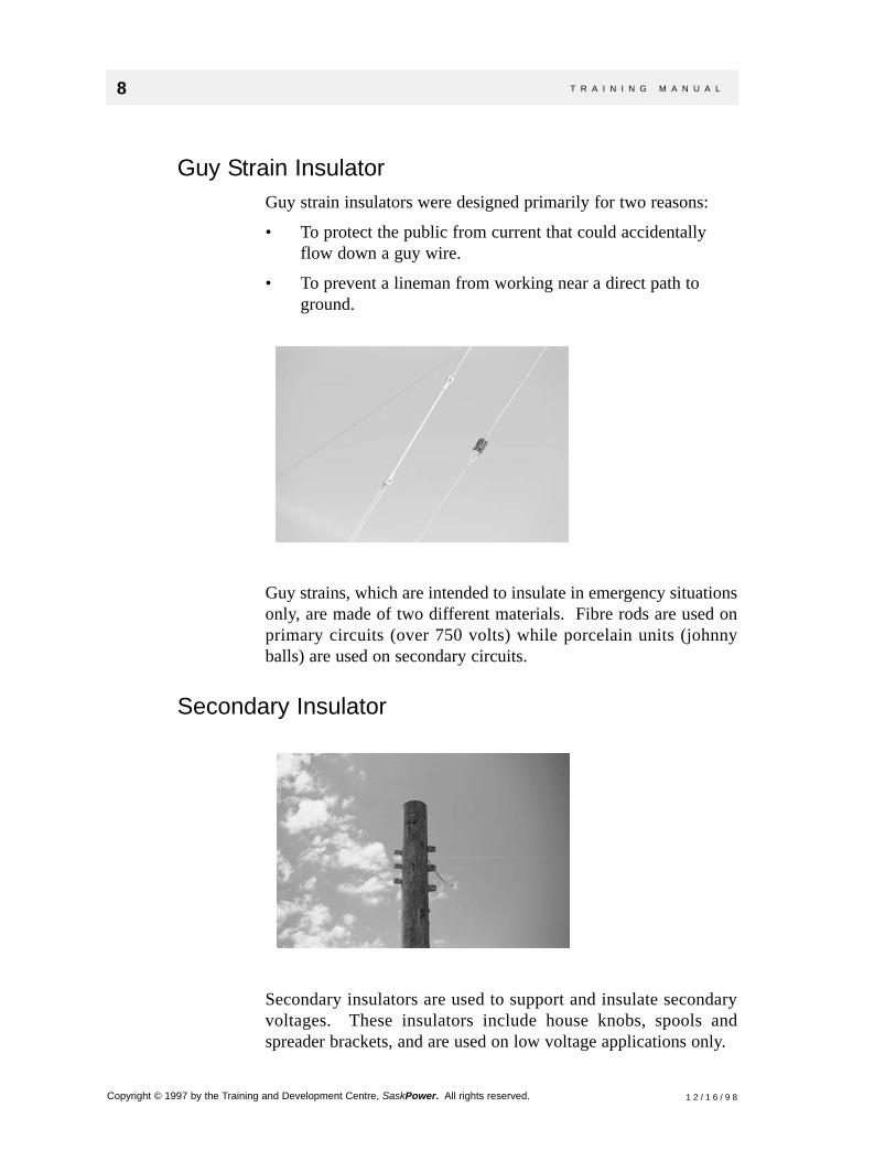
Guy Strain InsulatorGuy strain insulators were designed primarily for two reasons:
• To protect the public from current that could accidentallyflow down a guy wire.
• To prevent a lineman from working near a direct path toground.
Guy strains, which are intended to insulate in emergency situationsonly, are made of two different materials. Fibre rods are used onprimary circuits (over 750 volts) while porcelain units (johnnyballs) are used on secondary circuits.
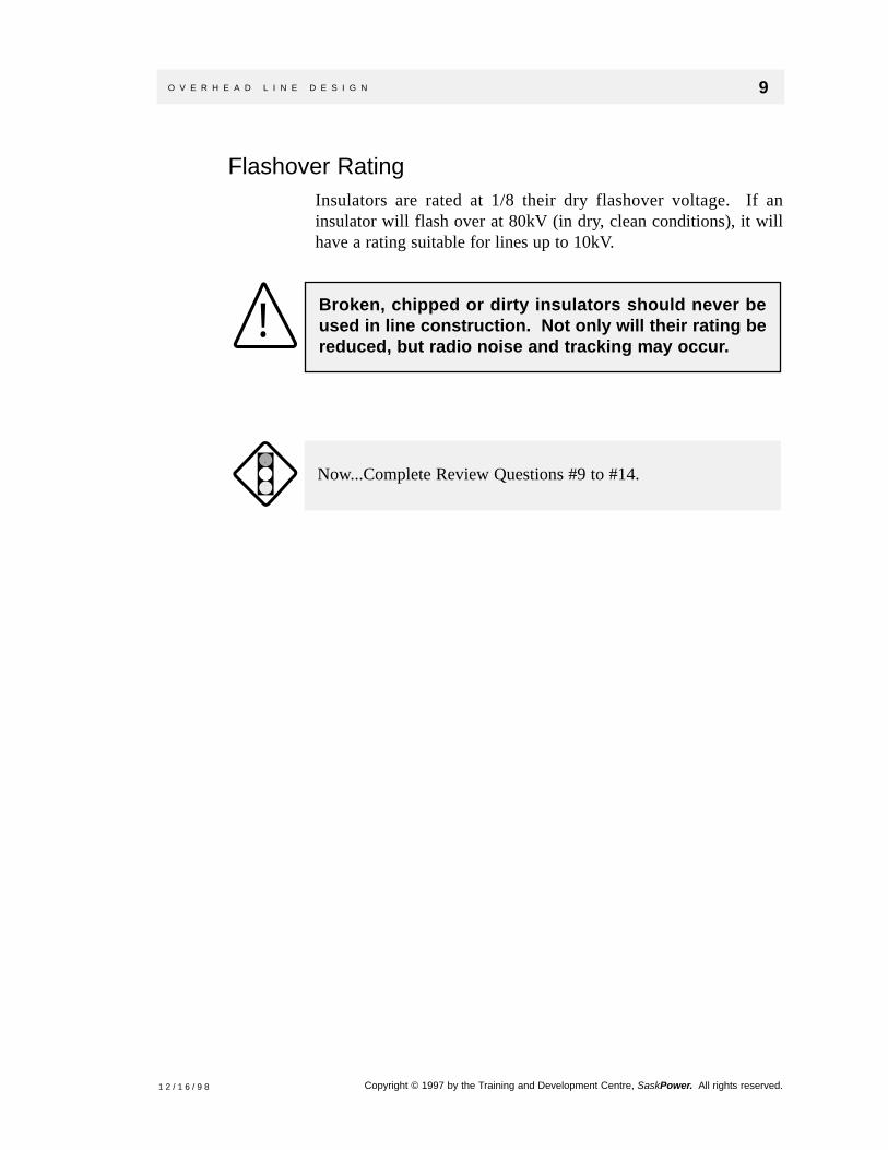
Secondary Insulator
Secondary insulators are used to support and insulate secondaryvoltages. These insulators include house knobs, spools andspreader brackets, and are used on low voltage applications only.
8 T R A I N I N G M A N U A L .
1 2 / 1 6 / 9 8Copyright © 1997 by the Training and Development Centre, SaskPower. All rights reserved.
Flashover RatingInsulators are rated at 1/8 their dry flashover voltage. If aninsulator will flash over at 80kV (in dry, clean conditions), it willhave a rating suitable for lines up to 10kV.
Now...Complete Review Questions #9 to #14.
Broken, chipped or dirty insulators should never beused in line construction. Not only will their rating bereduced, but radio noise and tracking may occur.
!
O V E R H E A D L I N E D E S I G N 9 .
1 2 / 1 6 / 9 8 Copyright © 1997 by the Training and Development Centre, SaskPower. All rights reserved.

Line ConductorsWhen working with conductors, you will learn that sag is one ofthe most important factors besides resistance. Many factors willaffect the sag of a conductor, which in turn, can increase ordecrease ground clearance.
There are five factors which affect sag:
• Elasticity
• Span length
• Weight of the conductor
• Temperature of the conductor
• Tension
ElasticityIf you have sagged wire before, you will know there are two sagcharts for each condition; initial and final. Anytime a newconductor is sagged, it is pulled a little tighter to allow for the“stretching” a conductor is subject to (wind and ice loading). Thisis the initial sag.
After the wire has been subject to the forces that will stretch it, sagwill increase a given amount and then stretch very little after. Thisis called the final sag. Anytime a used conductor is utilized, it mustbe sagged to this chart.
Span LengthSpan length is the distance between two supports. A line with longspans has more conductor so the weight is increased. This weightwill cause the sag to increase.
Weight of Conductor (or Type)A heavy conductor will sag more than a light conductor. This iswhy 3/0 ACSR conductor will have much less sag than 3/0 copper.
Temperature of ConductorMetals expand when hot and contract when cooled. This is alsotrue with conductors.
10 T R A I N I N G M A N U A L .
1 2 / 1 6 / 9 8Copyright © 1997 by the Training and Development Centre, SaskPower. All rights reserved.

TensionThe higher the tension a wire is subject to, the less sag a line willhave. One may consider pulling the conductors extremely tight toincrease clearance, but there are several reasons why this is notdone. First of all, tension must be well below a conductorsbreaking strength. If a conductor is too tight and severe loadingoccurs, it will break.
A second and more important reason to keep the conductor tensionlow, is vibration.
VibrationThere are two types of conductor vibration:
• Aeolian vibration
• Galloping vibration
Aeolian VibrationAeolian vibration is caused when steady crosswinds (0 - 19 mph)create eddies alternatively above and below a conductor. Thisvibration occurs more often as conductor tensions increase; whichin turn, cause strands to break, hardware to loosen and conductorsto fail.
Besides keeping conductor tension low, “dampers” are also used tocombat this type of vibration. Dampers are devices that absorbvibration energy. They must be placed at the peak of a wave(distance from insulator varies with conductor) to work properly.
There are many different brands of dampers but they generallyfollow two principles. Some use weight (Stockbridge), whileothers use a tight wrap (Slapac) to absorb vibration.
Stockbridge damper
O V E R H E A D L I N E D E S I G N 11 .
1 2 / 1 6 / 9 8 Copyright © 1997 by the Training and Development Centre, SaskPower. All rights reserved.
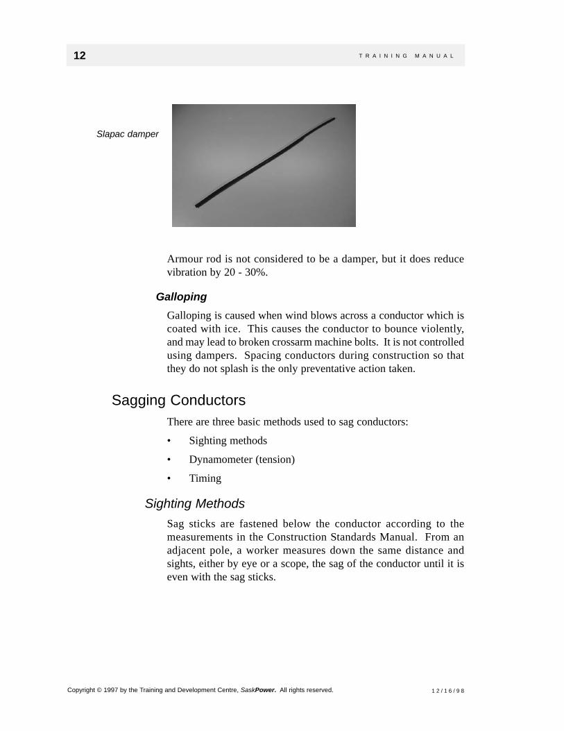
Armour rod is not considered to be a damper, but it does reducevibration by 20 - 30%.
GallopingGalloping is caused when wind blows across a conductor which iscoated with ice. This causes the conductor to bounce violently,and may lead to broken crossarm machine bolts. It is not controlledusing dampers. Spacing conductors during construction so thatthey do not splash is the only preventative action taken.
Sagging ConductorsThere are three basic methods used to sag conductors:
• Sighting methods
• Dynamometer (tension)
• Timing
Sighting MethodsSag sticks are fastened below the conductor according to themeasurements in the Construction Standards Manual. From anadjacent pole, a worker measures down the same distance andsights, either by eye or a scope, the sag of the conductor until it iseven with the sag sticks.
Slapac damper
12 T R A I N I N G M A N U A L .
1 2 / 1 6 / 9 8Copyright © 1997 by the Training and Development Centre, SaskPower. All rights reserved.

DynamometerA gauge called a dynamometer (which measures tension) is hookedonto the conductor and pulled until the tension is the same asspecified in the Construction Standards Manual.
O V E R H E A D L I N E D E S I G N 13 .
1 2 / 1 6 / 9 8 Copyright © 1997 by the Training and Development Centre, SaskPower. All rights reserved.

TimingBy hitting the conductor, a wave is started and is then timed to thenext structure and back. The length of time for the wave to returncorresponds to a definite sag. (This method is not recommended.)
Now...Complete Review Questions #15 to #26.
14 T R A I N I N G M A N U A L .
1 2 / 1 6 / 9 8Copyright © 1997 by the Training and Development Centre, SaskPower. All rights reserved.

System GroundsThere are two types of grounds used in our utility.
• Safety grounds
• Permanent system grounds
Safety grounds are usually temporary and used to de-energize linesor equipment while it is being repaired. Permanent systemgrounds, on the other hand, are a built in feature of our system(ground grids), that actually connects the conductors andequipment to earth. This is done for several reasons:
• Provides a return path for circuit current.
• Provides protection to equipment and personnel
• Maintains a definite voltage to ground.
Safety grounds
System grounds
O V E R H E A D L I N E D E S I G N 15 .
1 2 / 1 6 / 9 8 Copyright © 1997 by the Training and Development Centre, SaskPower. All rights reserved.

Provides a Return Path for Circuit CurrentIn order for a circuit to work, there has to be a path going to and apath coming back from a load. We are all familiar with the neutralused in cities to provide a return path. We may have also seenother utilities that use a neutral on their rural or three phase lines.
As a utility, SaskPower is fairly unique in the fact that it uses theearth as a conductor. The connection between the lines orequipment is done through “ground grids”. In towns, the systemneutral is connected to the grid and is, therefore, a part of thepermanent system grounds. However, on rural lines, no neutral isused.
Since the earth is the only return for circuit current, it is vital thatthe connections between ground wires and grids are well made.Ground wire size and ohmic values are found in the ConstructionStandards Manual. In fact, all of the connections and resistancesare checked using a “megger”. If the ohmic value is too high (largeresistance), steps must be taken to bring the values to an acceptablelevel. This is done by:
• Making better connections.
• Putting in more ground rods.
• Putting in deeper ground rods (use of extensions)
We know from Ohm’s Law (E = I x R), that high resistance has ahigher voltage drop than low resistance when subject to the samecurrent. This is how power is robbed from the system through poorground grids.
16 T R A I N I N G M A N U A L .
1 2 / 1 6 / 9 8Copyright © 1997 by the Training and Development Centre, SaskPower. All rights reserved.

Provides Protection to Equipment and PersonnelThe grid provides protection to employees and equipment. Anisolated line can be de-energized to the grid, provided the gridconductor is large enough to handle the amperage which will flowduring a fault.
Equipment ProtectionProtection of the equipment is done through OCR’s, breakers andarrestors. These devices will either divert electricity to ground toprotect the system, or sense the large amount of current flowing toground and “trip” or open a circuit. Lightning strikes are made tobypass equipment through to the earth via system grounds.
Personnel ProtectionSystem grounds for farms, substations and switches protect againstunequal potential for persons within the grid during a fault.
Maintain a Definite Voltage to GroundMost three-phase systems are a Wye (also called Star) system. Thissystem needs a reference to ground or voltages may fluctuate.
O V E R H E A D L I N E D E S I G N 17 .
1 2 / 1 6 / 9 8 Copyright © 1997 by the Training and Development Centre, SaskPower. All rights reserved.

SummaryIn this module, you have learned:
• The design of our electric system.
• The design of insulators.
• About conductor sag and vibration.
• The purpose of a system ground.
Now...
• Complete the remainder of the Review Questions.
• Clarify any concerns or questions you may have.
18 T R A I N I N G M A N U A L .
1 2 / 1 6 / 9 8Copyright © 1997 by the Training and Development Centre, SaskPower. All rights reserved.
REVIEW QUESTIONS
Overhead Line Design
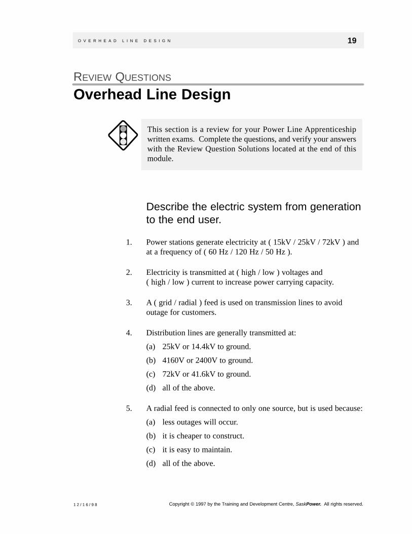
Describe the electric system from generationto the end user.
1. Power stations generate electricity at ( 15kV / 25kV / 72kV ) andat a frequency of ( 60 Hz / 120 Hz / 50 Hz ).
2. Electricity is transmitted at ( high / low ) voltages and ( high / low ) current to increase power carrying capacity.
3. A ( grid / radial ) feed is used on transmission lines to avoidoutage for customers.
4. Distribution lines are generally transmitted at:
(a) 25kV or 14.4kV to ground.
(b) 4160V or 2400V to ground.
(c) 72kV or 41.6kV to ground.
(d) all of the above.
5. A radial feed is connected to only one source, but is used because:
(a) less outages will occur.
(b) it is cheaper to construct.
(c) it is easy to maintain.
(d) all of the above.
This section is a review for your Power Line Apprenticeshipwritten exams. Complete the questions, and verify your answerswith the Review Question Solutions located at the end of thismodule.
O V E R H E A D L I N E D E S I G N 19 .
1 2 / 1 6 / 9 8 Copyright © 1997 by the Training and Development Centre, SaskPower. All rights reserved.
T / F 6. A step-down power transformer reduces distribution voltages tohousehold voltages.
T / F 7. Large amounts of current are best transmitted for short distancesrather than long distances.
8. Distribution transformers lower distribution voltages to:
(a) feed streetlights.
(b) supply electricity to houses or businesses.
(c) secondary conductors.
(d) all of the above.
Explain the types of insulators used in linedesign.
9. Insulators are rated at ( 1/4 / 1/2 / 1/8 ) their dry flashovervoltage.
10. An insulator rated at 25 kilovolts will arc over at:
(a) 15kV.
(b) 25kV.
(c) 200kV.
(d) 120kV.
T / F 11. Insulators can be made of porcelain, glass or epoxy.
T / F 12. Suspension insulators should never have insulators added toincrease the insulation rating.
20 T R A I N I N G M A N U A L .
1 2 / 1 6 / 9 8Copyright © 1997 by the Training and Development Centre, SaskPower. All rights reserved.

13. Match the statements on the right with the insulators on the left.
T / F 14. Insulators with chips or cracks are safe to use if the damage isminor.
List the five factors affecting sag.
15. List the five factors affecting sag.
16. After a conductor is subjected to wind and ice loading, it’s sagmust be found using ( initial / final ) sag charts.
T / F 17. Conductor tension must not be exceeded or conductor damage canoccur.
___ Used where large tension exists.
___ Used on long spans and high
voltages.
___ Used on narrow right of ways.
___ Used to protect public and
personnel.
___ Used on secondary voltages.
(a) Suspension
(b) Spreader
brackets
(c) Strain
(d) Guy strain
(e) Post
O V E R H E A D L I N E D E S I G N 21 .
1 2 / 1 6 / 9 8 Copyright © 1997 by the Training and Development Centre, SaskPower. All rights reserved.

Explain the purpose and types of dampers.
18. Dampers are used to control:
(a) aeolian vibration.
(b) galloping.
(c) high conductor tension.
(d) none of the above.
19. A damper must be placed:
(a) a specified distance from an insulator.
(b) at the peak of a wave.
(c) correctly to work properly.
(d) all of the above.
T / F 20. Aeolian vibration is caused by steady crosswinds blowing acrossan ice laden conductor.
21. Galloping is best controlled with:
(a) dampers.
(b) ACSR conductor.
(c) cannot be controlled.
(d) none of the above.
T / F 22. Dampers are used to absorb vibration energy.
T / F 23. Galloping is caused when wind blows across ice ladenconductors.
24. Conductor spacing is used to prevent phases from splashingduring:
(a) aeolian vibration.
(b) galloping.
(c) strong crosswinds.
(d) none of the above.
22 T R A I N I N G M A N U A L .
1 2 / 1 6 / 9 8Copyright © 1997 by the Training and Development Centre, SaskPower. All rights reserved.

Explain the methods used to sag conductors.
25. What are the three methods used to sag conductors.
T / F 26. Using vibrations or waves to sag a conductor is referred to as thesighting method.
T / F 27. A dynamometer measures tension in a conductor.
Explain the purpose and types of systemgrounds.
28. List the three ways used to improve the ohmic values of groundgrids.
29. The fourth wire on three-phase rural systems:
(a) does not exist.
(b) can only be strung with a neutral conductor.
(c) is an earth return.
(d) none of the above.
30. The resistance of ground grids must be ( high / low ) to allowearth to provide a good return path.
T / F 31. Temporary grounds can utilize ground grids provided theconductor will handle large fault currents.
O V E R H E A D L I N E D E S I G N 23 .
1 2 / 1 6 / 9 8 Copyright © 1997 by the Training and Development Centre, SaskPower. All rights reserved.
32. List the three purposes of a permanent system ground.
T / F 33. System neutrals are never hooked into permanent system grounds.
34. A ground grid should always:
(a) be checked with a megger.
(b) have good connections.
(c) be treated as “alive” on an energized transformer if cut.
(d) all of the above.
Now...Ask your Instructor for assistance if required. Additionalexamples may be available.
24 T R A I N I N G M A N U A L .
1 2 / 1 6 / 9 8Copyright © 1997 by the Training and Development Centre, SaskPower. All rights reserved.

O V E R H E A D L I N E D E S I G N 25 .
1 2 / 1 6 / 9 8 Copyright © 1997 by the Training and Development Centre, SaskPower. All rights reserved.
REVIEW QUESTION SOLUTIONS
Overhead Line Design1. 15kV
60 Hz
2. HighLow
3. Grid
4. a
5. b
6. False
7. True
8. d
9. 1/8
10. c
11. True
12. False
13. c, a, e, d, b
14. False
15. ElasticitySpan lengthWeight of conductorTemperature of conductorTension
16. Final
17. True
18. a
19. d
20. False
21. c
22. True
23. True
24. b
25. Sighting methodsDynamometerTiming
26. False
27. True
28. Better connectionsDeeper ground rodsMore ground rods
29. c
30. Low

26 T R A I N I N G M A N U A L .
Copyright © 1997 by the Training and Development Centre, SaskPower. All rights reserved. 1 2 / 1 6 / 9 8
31. True
32. Provide a return path forcurrentProvide protectionMaintain a definite voltageto ground
33. False
34. d
REVIEW QUESTION SOLUTIONS (CONTINUED)Overhead Line Design