Transistion from TVSS to SPD
24
Compulers Electronic Ballasts Cosh Registers ATMs Building Automation HVAC Systems Manurocturing Equipment Medical Equipment Drives PlCs Electronically CantraUed Motors Security Systems Audio & Video Equipment Telephones Sensitive Electronics - Presented by Gary H. Fox PE. Senior Specification Engineer Tuesday, September 22, 2009 The Transition From TVSS to SPD Surge Device Standards & UL 1449, 3 rd Edition Changes What is Transient Valtage ? External Sources = 20% of all transients High level surges - Immediate Catastrophic Damage Examples: • lightning • Utility lood switching • Fault Clearing • Crossed Power lines • Damaged transformers ..,.... ':.';,,;: Va/tape splkesare high energy short duratIon transient voltoge events that damage or destroy senSItive electronic equipment All equipment with printed circuit boards and microprocessors ore susceptible to transient surge damage. Equipment Affected Definition Effects of Transient Voltage (Surge) Lightning Flash Density Permanent Damage to Sensitive Electronic Equipment Erratic Control of Electronic Loads Control Failure System Down I Operation Interrupted Cost of operation down time Lost of productivity ..'IIh ............. ....oto>Iogr """'.... , ...h ... <1'''''''''''''''.:1_ WSA 010 ,4I(l'..J-OOj _ll!l (1......-2!l'aJ .""........ . --_._ . • imagination at work 1/ GE /
-
Upload
michaeljmack -
Category
Engineering
-
view
219 -
download
5
Transcript of Transistion from TVSS to SPD

CompulersElectronic BallastsCosh RegistersATMsBuilding AutomationHVAC SystemsManurocturing EquipmentMedical EquipmentDrivesPlCsElectronically CantraUed MotorsSecurity SystemsAudio & Video EquipmentTelephones
Sensitive Electronics
-Presented by Gary H. Fox PE. Senior Specification EngineerTuesday, September 22, 2009
The Transition From TVSS to SPD
Surge Device Standards &UL 1449, 3rd Edition Changes
What is Transient Valtage ? External Sources = 20% of all transients
High level surges - Immediate Catastrophic Damage
Examples:
• lightning
• Utility lood switching
• Fault Clearing
• Crossed Power lines
• Damaged transformers
..,....':.';,,;:
Va/tape splkesare high energy shortduratIon transient voltoge events thatdamage or destroy senSItive electronicequipment
Allequipment with printed circuitboards and microprocessors oresusceptible to transient surge damage.
Equipment Affected
Definition
Effects of Transient Voltage (Surge) Lightning Flash Density
Permanent Damage to Sensitive Electronic Equipment
Erratic Control of Electronic Loads
Control Failure
System Down I Operation Interrupted
Cost of operation down time
Lost of productivity..'IIh ............. '~11c:....oto>Iogr """'.... , ...h ~...
COoI>aI""~"""""OI~,"""'lm-F."....,.Wll""'.""t""_<1'''''''''''''''.:1_WSA 010 ,4I(l'..J-OOj _ll!l (1......-2!l'aJ ."".........--_._.
• imagination at work1/
GE /

Internal Saurces = 80% of all transients
low level repeated surges - Damage Over Time
E)(omples:
• Compressors• Inductive loads
-li.e) motors & pumps• HVAC Units• Elevators• Drives - control elevators!• Laser copiers •• Cleaning equipment
-Vacuums, Floor polishers
Standards
NEMA LS-1- 1992Low Voltage Surge Protective Devices
NEMA LS-l standard was established in 1991lo serve as 0 uniform spKifict:lt!ongu(d~ine for low voltage surge protective devices.
NEHA 1S·1 providn minimum parameters and definitions thot make up thecontent of 0 proper SPO (TVSSI specification formal
Int."t of NEMA L5-11s to be generol in naturllt and !'lOt to introduce standards,derive lesting methodology or elrtenslVi! vocobulol)l.
Key palllmetfn addressed in the NEMA LS-1 Sf)« fannat llfe:
MCDV (MaKimum Continuous Dperatil'lg Voltagel
Protected Modes Definition (L-N, L-G, L-!.. N-Gl
Single Impulse Surge Rating
Clamping Voltages per C62.41Sofety Ageney Approvols by NRTL lUI.., CSA etc..)
Natoli NEMA l5-1 parameters are rrquirftl forcompkte spKificotion ofollSPDdlfVlcu.
IEEE StandardsIEEE C62.41.1- 2002 Guide on the Surge Environment in LowVoltage
AC Circuits
IEEE C62.4L2 - 2002 Recommended Practlc. on the Characterilatlonof Surges in Low-Valtagf AC power Circuits
IEEE (62.45 - 2002 Recommended Plllctke on Surge Testing forEqu!pment Connected to LV AC Power CirC\l;U
IEEE C62.62-2000 Standard Test Specifications for SurgeProtective Devices for Law-Voltag, AC PowerCircuits
IEEE C62.72 - 2007
IEEE1100-200S
Guide forth, Application of Surge ProtectiveDevices
Recommende-d Practice for Pow,ring andGrounding Electromr'llc Equipment(Emerald Book!
TVSS OverviewTVSS Standards
Standards? Recommended Practices? Guides?What's the Difference?
IEEE Standards - Categorized
ANSI/IEEE
UL 1449
UL 1283
NEC
NEMA
C62.41, C62.45, C62.62,
C62.72,1100
TVSS Safety Standard
Noise Filtering
Article 280, 285
LS-11992
Standard:
Reed Practice:
Guide:
Mandatory requirements. Uses theword -Sholl"
Procedures and positions preferredby IEEE: -Should"
Alternative approaches listed. Noclear cut recommendation
• imagination at work2/
GE /

IEEE C62.41.1 - 2002Guide on the Surge Environment in Low Voltage AC Circuits
IEEE C62.41.1 provides information on surge voltages. currents and lOVthot Off propagated In low-voltage oc power circuits and charocterizesthe surge environment
Provides pll;lcticol bosis for the selection of voltage and curnn! tests forsurgewithuond of elKtronic/eTectricol equipment
Key orlClS oddrused:
Provide bask information on surgesOrigin of Surges
Propa~on, dispersion and mitigation of surges
Rate of Occurrence and Voltoge Lenis in UnprotKted Circuits
Octobase of observ~ sUfge behaviorReference document for C62.41.2
IEEE C62.41.2 - 2002Re<:ommended Proctice on the Characterization of Surges in low-VoltageAC power Circuits
IHE C62.41.2 choroctrrins the su'gl environment at locations on acpower circuits dncrilad In IEEE Sid C62.1I1.1-20C12 by means ofstandardized waveforms ond other stren paramettfl.
HOT A PERFORMAHCE STANDARD
Key arlal addr'llId:
Waveshapes of Representati~tSurge Voltages, Entrgy andSOutCt ImptdafICt
Location Categories relative to position ftom Service Entrance
Rtpreuntati~tSurgt Wavtforms for eoch cattgory
IEEE C62.41.2 - 2002Recommended Practice on tne Ctloracterization ofSurges in Low-Voltoge AC power Circuits
Surge Exposure Locations
Cottgory C " Service EntraflCeHigh - Medium Exposure lVSS
Cottgory 8 • Service/Distribution IShort Run Branch PontlsMedium - Low Exposure TVSS
Category A • Long 9ronch PonelllPoint of Use Locotions more thonlUmfrom CoL B or 20m from Cot. CLow Exposure TVSS
• imagination at work
IEEE C62.45 - 2002Recommended Practice on Surge Testing for EquipmentConnected to LVAC Power Circuits
'EEE C62.4S provides 0 recommend proctiCt for tht ptnormance of surgettsling on tltctricol ond tll:cttonic system cormected to low voltogt oc powtrcircuiU.
Provides guidofICt for specifying and opplying sU'llt ttsting equ!pmtnt toelectrical devices subject to transitnt voltages.
KlY areas oddrlssed:Provides general surge test plan recommendations
Test methods to aid in dtsign. quality control, acceptonce andtroubleshooting.
C62.4S Is II guid.lln. only. Sptclficatian or Ptrlonnonce tnU lor anyparticular type of l:Quipment rtmains the prerogative of tlttmonufacturu, user, and standards group involvl:'<l.
IEEE C62.62 - 2000Standard Test Specificotions far Surge Protective Devices
IEEE C62.621s a successor document to rEEE 62.41 standards.
thell provldts usus. indtptndtnt laboratoriu and manufactur.rs with test
sp.cificatlons and tuting mtthodologies for Surge PTotl:ctlvt Dtvicu.
KIY OriOI addrlllld:
Ottai!s testing sptclficatlons for
Moldmum Continuous Optratln.g Valtoge
Ma><imum Single Withstand Surge
Minimum Surgt Lile Withstand
Surge Ruponst Voltoge (clamping voltagtl
IEEE C62.72 - 2007Guide for tlte Application of Surge Protective Devices
IEEE C62.72 providts speclfil:r$ and users of SPO's with on understonling ofnumerous application considtfOtions to be eva!uatl:'<l befOfe SPD's ore installedIn low voltoge AC power circuiU.
Key arias oddrlssed:
Defines considerations fOf the SPD stlectlon procen
Dtscribes Surgt Origins, Eflecu, and Mognitudes
Location Categories and Power DistributionSYlttmsandCanfigurot/ons
Grounding and Sonding
Protected Modes
SPD Sptcifications
SPD Failure Modes
{~ SPD Systtm Coordination and Methodolog;es~"'''''''I'''~'''"'''·.'''
3/GE /
UL 1449 2nd Edition
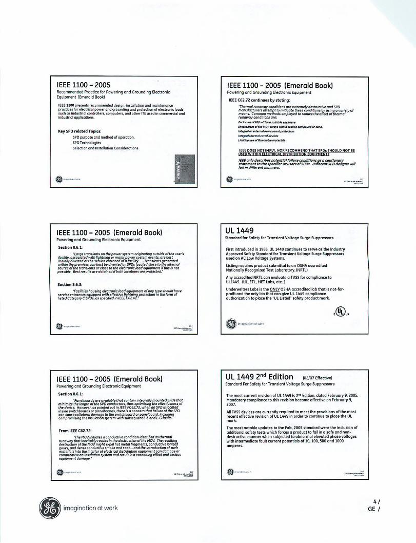
IEEE 1100 - 2005Recommended Practice for Powering and Grounding ElectronicEquipment (Emerald Bookl
JEfE 1100 presents recommended design,lnstaliation and molntenanceproctlces for electrical power ond grounding and protection of electronil; foodssuch 05 industrial controllen, computers, ond other ITE used In commen:iol andinduitriol applIcation$.
Key SPO r.lat.d Topics;SPD purpose end method of operation.SPDT~hnologje5
Selection and Installation Considerations
IIEEE 1100 - 2005 (Emerald Book)Powering cnd Grounding Electronic Equipment
Section 8.6.1:
'lorg' transienls on th.pow.r IYS/lm originolinlllNfSidr of/heusrr'sfocility. OUr>cKlt~with lighlnlng or mojor POIWf system IWlnls, 0,. best
~;~~;;>;g:':;;:::5f~~~~:~~:':J:~~c~o£:£~~7cjCaf:d~'6~nt~Fllrr7:t~~1$ourc,o'I'" trclluirnrs or C/O$.IO th. fl/ec/ronic lood equipment if this is notpossible. 8est ,,5ults ortobtoined ifboth locotlons artproteeted."
S,ctlon 11.6.3:
"Focililits hOU5i~ el.ctronk load I'quipmenl ofony type should hOlle
~i~~~~~f:;c:,~~ t~8t:~5 spW:,/:fj':J';~I~n~~ttproteel/on in the form of
IEEE 1100 - 2005 (Emerald Book)Powering end Grounding Electronic Equipment
S,ctlon 11.6.1:'Pont/boords Ort cwoiloble thot contain inlef1rolly mounted SPOs that
~~~~:.~~;~~~~~h;;~r~oo~i~IIErh~~~~:":v1{e~~~~~~i~'f~~:r:~ ofinside switchboords orpan.lboards. thffe is 0 conetm thot fai/urt ofth. SPO
~~~~~~;:i;i~~Ot~;~~~~/~t;g~ ;~5tt~t,:::·:~hsbuob~:r,~~~r~i~~dt:1?~~~1:~.~
From IEEE C62.72:'h.MOV inilialfS 0 condllctiv. condition idenlified as th.rmol
runaway lhot inevitably rtsUlts In tIM dtstruction of the MOV. Th. r.sulti"f1dtstruclion of the MOIl might txpel hot metol ~ogm.ntst condlletive ioniztdgas.s. and d.nu conductive smoke and sooL~ond the mtroduction ofsuchmal.rials inlo the inlfriorof.ltetrical distribution I'qulpment con domog. orcompromiu on Insulotion syst.m and rtsult in 0 caseadinf1 efftet ond 5ffious.qulpm.nt domaf1e.·
IEEE 1100 - 2005 (Emerald Book)Powering ond Grounding Electranlc Equipment
IEEE C62.72 tontlnues by stating:
'Th.rmal runoway conditions a" fXIJ".m.1y d.struetivt ond SPO
:::~~~~~~~o~~~~~s ~~E~~':::;~~~I;g~~r;;%t1~7fh~~~~1ty ofrunoway condillons 0":l<ldot;u.-.DiSPO w/fAIn" w/t,,!HHtClolur.
Inctu"","'Dit"'HOII_w/fItltl_lIngcon>~Of"_.
Inf"9'"QIOf".itUfn<I/~fpr«_1on
"""9"'lfJ.nr!<lICUfDlf"-b.Utnitlng_Di"""'-IW__
IEEEonly d.scrlb#s pot.ntlal falfun conditions as a cautIonaryrtat.m.nt to th. sp«lfi.r or us.rs ofSPOs. Olff.r.nt SPO dfilgns willfolf In dfff.nnt mannlN'S.
UL 1449Standard for Safety for Transient Voltage Surge Suppressors
First Introduced in 1985. Ul1449 continues (0 serve os the IndustryApproved Safety Stondord for Tronslent Voltoge Surge Suppressorsused on AC low Voltoge Systems.
listing requires product submittal to on OSHA occreditedNotlonolly Recognized Test loborotory. (NRTU
Any accredited NRTl can evoluote a TVSS for compliance toUll449. IUL ElL MET Labs. etc_I
Underwriters lobs is the Qt:l.LY. OSHA accredited lab that is not-for·profi( ond the only lob thO! can gille Ull449 complianceauthorizotion to ploce the "Ul listed" sofety product mark.
(02107 Effective)Standard For Sofety for Transient Voltoge Surge Suppressors
The most current revision of Ull449 is 2"" Edition, dated February 9. 2005.Mandotory complionce to this revision become effective on Februory 9,2007.
All TVSS devices ore currently reqUired to meet the provisions of the mostrecent effective revision of Ul14491n order to continue to ploce the Ulmark.
The most notable updates to the F,b, 2005 s(andotd were the Indusion ofodditionolsofety tests which farces a product to foil in a sofe ond non·deslnJctive manner when subjected to abnormal elevated phose voltageswith intermediote fault current potentials of 10. 100. 500 ond 1000omperes.
• imagination at work
."'''.0:.=:
4/GE /

UL 1449 2nd Edition '02107"''''''••'Standard For Safety for Transient Vohoge Surge SuppressorsFun Phose Voltagl Short Orcult lut and limited Current OvlrvoltoglT,st Fallur. Unocceptable Results lOuring and Following Tlsts);
01 Emission ofl\ome, molten metal. glowing or naming particles throughony openings (preexisting or created as 0 result of the test) in the product.
bl Charring. glowing. or flaming of the supporting surface, tissue paper, Of
cheesecloth.
cllgnition of the enclosure.
dl Creation of any openings In the enclosure thot result in occessibility oflive potU. when f'\Ioluote<l in accordonce with the occl!ssibiJity of live portstnt in S5A.2.
ellen of structural integrity to (I degree thot the equipment collapses oreKPeriences such displacement of ports thot there is (I risk of shortcircuiting or grounding of current-carrying ports.
TerminologyType 1 _ Permanently conneaed SPOS Intended for InstoUotion betwHn theSKOndery of the service troMfOfTMf ond the line $Ide of the serviu equipmentO\ItfCWTent device. os -U lfli the load side, including wott-kour mtItf sodtet
enclosures and intended to be instolll'Cl without on Vdemol oYIrCWTem prctK1ivediMe•.
T)'lMl Z _ PI!f1TlCfm\t!yCOMKted SPOS intended for Installation on the load side ofthe servic:. equipment overanltflt devic., inducing SPOt locoted at the tKondI......T)'lMl J _ Point-Qf·utililotion SPOt, instoUl'Clat 0 minimum cww:Iuetot length of JO ftfrom the e1ectricol service ponti to the point of utililOtion. ~Il~ cord connKted. dirKtplug.... rKeptode type ond SPOt iMUlDed at the U'tilil'O'tion equipment beingprotected. The distanc. CO ftI is .xdusiw of condl.lClors provided with or used to
attochSPOS..
Type" - Component SPOs and componltflt ossemblies.
.._.-:.=:
Types of Metal Oxide Varistors (MOVs)
"'1'" linn mod.11 or••qlllpp.dWltll EnhGnctdThormGIIy PrGlnt.d M.IGI O-'Cid.IIGriIlGrfTPHOV)TKhnCllogy
TPHOV Ftot""t1
• SGf.ty ftmOYts HOV "om circuit prior to .... ptuf. whtn'!<9oud to Glmormol Of su,t<lin.d pho.. owrvollog.tv.nll
........... GE TVSS to pall 011 Ull'19foll!:CUfftnt TUII'ndU<lmg feb. z007 rtvlsionll ....tIlout til. n.td fOfoddltlonal up.trt<lm .......<u,..nl Pl'llltCtlotl.. ,...-:.....::
UL 1449 3rd Edition: What is changing?
Nominal Discharge Current - In
- Value is selected by the manufacturerType 1 SPO con be either lOkA or ZOkA
• Type 2 SPD can be 3kA, 5kA, lOkA or 20kA
'- Nominal dischorge current level is morked on the label of 5PD
- Test subjects SPD to a total of 15 impulses
-In order to successfully pass test:SPO connot create a shock or fire hazard during the lest
Nothing in the surge poth can open at any time during or after the lestllncJudes olllnternoJ and lilt.mol d.vlces, such as fusn andlor circuitbreokersl
.._.-:..=
Measured Limiting Voltage Test
2nd EditionL Tton1itnIVCIltog. Surge SllJIptt110t"',,,,t. Fordtvict1oncif<urts6DD\/OtI.n
" su!V. Voltog. I(e*'9 !MtI., CuI)I'C.,.:!.Tt1tIIIQ IiW/SOCI,t"
S. lnstolctlon ""Icod tid. onIr
3fd EditionL Sllt9.Prolt<_OtvI<.ISPOI
-olIO includ.IIKondOf)' SUfg. onulOts
l. Fotcltvict1 on w<..u 1.OOOYorl.1t
J. 110li<l;. P'OIt<!ion I(Cli~IIIPIt.I
'" Nomil\al D1Kharg. CWTtrrt Iiwn \A ll.
S. Type 1 c1_t1 cen btlfl1toltdon ... 1>cI.otlooclsicl.
6, Typell,l,_dtvict1
7, ._011 NotlOMI Slondo,c1lANSlI
• Results in Voltage Protection Rating (VPR)
• Uses a 6kV/3 kA combination wove surge{current is 6X greater than SVR test using6kv/SOO A combinotian wove!
• Higher current levels will produce higher VPRratings, when compared to 2" edition SVRratings for an identical device
UL Sfandord is now more similar to the lEe Standard_. And complies with changes in Z008 edition ofNEe
f»!'~'""-'
• imagination at work5/
GE I

Lightning Protection Systems
• UL96A - Installation Requirements forLightning Protection Systems
• Requires a Type 1 or Type 2 SPD rated 20kAnominal discharge current 11,1
• NFPA 780-2008 is in line with UL96Arequirements
• Nate: all GE SPD devices will be certified forUL96A usage
SPD Component Technologies
• Metal Oxide Varistors (MOVs)
• Selenium
• Gas Tubes
• Hybrid
••••
.._.-:..=:
Frequently Asked Questions: Types of Metal Oxide Varistors (MOVs)Q.~
Q.~
Q.
Q.~
When don thl UL 1/149, 3"' edition go Into .".ellSeptember 29, ZOO9 INo,lnlt/olly the date lhot the 3'" edition wcs to toke effect,but UL stm hos (I lorg. backlog. Mlgrs con b. gronted a limited Intoslon.
Whet Is th,lmpo(t on my u:lsting TVSS Installations?Nothing. Th. chong" In th. stondord onll offm produtU mOllllfocfuffdon orofttr th. 'fftctivi dati. Any ......sting inlto lotions witlstill be In UL compliance.
What Impact don thIs hall' on my existing stocklln~ntory?Nothing. The chong•• In thl standard only affect product that II monufocluffdon or oft,r Septtmb,r 29. 2009. Any .lei,tlng stack monufoctur.d Mfore thisdatI will still be in ULcomplloncl.
Don this rnt(Inthctpf'OdlKt$ c:ertifi"ll to UL 11149. 2"" edition or. nolOI me orItffectlwlSom, monufoctur«l may bemaki~change. to their products In Mdel'" tocom~with 3"' editlon. GE'llinlt of curnnt TVSS productl olr~colTllllv with3.. ltdltion ItOndarcli. Thltfltfore. _ orlt ~t chonglng OUf dnlgnIn ortJ~ toobtoln 3" edition Cltrt/fk;atlon.
II GE dlo"llin9~r SPD productl1 Will thittlt bit nM ccrtolog nurnbitn1GE II nllt~ng thItIr pl"oductl in order to compfy with 3" edition. Onelt Witobtoin~ Itdition cltftiflCatlon _ ....ilI~n IobItling all product 01 3'" ItditiOtlcompllonL
.,.._.~
High En"gy Metal OxideVaristor Components
Many ManufactureNi U..Small", Electronic Grode
MOV Arrays
.,.._.-=:
General SPD Information
• imagination at work
SPD TermsModes of Protection
L-N L-GA
B
C
N
G
.. ,....~
6/GE /

SPDTerms"Mode" vs "Phose" Rating
L-N L-G
SPD Maximum Surge Current RatingSurge Severity Ratings Per Made
25 - 50kA
65 -100kA
100-300kAHigh Exposure
Low Exposure
Medium ExposureN-G
L-LA
B
C
N
G@ + @ 1=2001
~__•__. Mode x 2 = Phase Rating
SPD ApplicationCascading System Wide Protection
ANSI/IEEE 1100 Emerald Book Guide to SPD APPcUcotlonOutlinu coscading SPD approach for all calflgorics and flxposurll/'HI,
HIgh tivil voltage spikes con get post leIVlce entronCIIVollog. spikes from high kA trolls/,nls con stilldomal1l1 downJfrrom IIqu,pmllnl SPD InstallationInternally glneratld transients - 80% of all transientsServiclI IIntrance SPDconnOI provide prolfction from In!troo! ,urges
Un'Kplcted IIlt.rnol transllnts In distribution - 1.11. Rooftop AClightning strikes On building or nrorby bring highkA tronsiems Inro diSlribulion
Redundant layered prot,ctlon at multiple levelsAddiliono/'aym protllct sensitive e!t<:lronln Ifupstrtom devicn fail
SPD Application
Integral Switchboard" PanelboordNew constructionNew panels or §witchboords on eKistlng facility
80M Extenllon
Add to eldsting facility elKuicol distributionWhen bronch ponel disconnect is required
Wall Mountedl7''''1i"'i1 New ConstructionU I~ Add 10 eldsllng focility eleet:ricol distribtltionn IImuJ When branch ponel disconneet: Is required
SPD - Installation Options
Paint af U..Category'"
ANSI/IEEE C62.41"Cascading Approach"
Dlrtrlbutlon
""""" B
Holn
service Entra~CategoryC
• imagination at work7/
GE /

Integral Advantages -Better p.rforma~owr Wall Hountitd units
~=-~... c~...... ""'""-Shorter ~PO leads .. Britt( surgor rtduetion
IWall SPOt;e SavIng.
ltoves mort spoce for odditlonolpon,l, and gear
plOCfmrnt in tight "'elricol roomsFactory Installed and Warranted
Avoid Instollotlon errors, splicing or locollon probillms IIIlabor_lngs
1.5 hours on overog' conlroclor lobor savings per SPD instolled
flush mounting behind panel door
Mounts bl/hind door in bronch ponl/ls and flush wilh switchboards andpowerpone/s
UL 61,891 Llsted
Enf;TII Ponti &Swifchboard ourmbli.s wilh SPD hovlI bun UL lrstrei
t1t~_."'''w-:.;;;,;;:.:
SPD InstallationSPD Connection - Wire Length Effects Study
In ZOO4, GE controet.,j A&' Laboretori'lln Conlhallock.n p~ to p.rlorm .urgeluting on a .Imulotld .Iectrical dl.tribution ,v"l.m with SPo Inilolilld.Th' purp01f oflh tell WO, to d.t.rmln. th• • ",~t, of(obl.l.ngth on SPOp,rformonct.Both inttgroUy mounttd ond woll mounted SPO dnign, w.I.lndud.d In th. tntWoll Mount SPO. w.r. fYoluottd wh.n (onnect.d ot I,ngth, 01 J' ond 10'.Integrol SPO, w.r, (onnect,d to th. dl'trlbution ,q"pm,nt bUI.IEEE recommend.d ,urg. wawform' w'r. InJect.d ot th. moln lug, of th.,1,ctricolpon,l.L.t thru voItognw.r, coptured and r.cord.d down.tnomfrom the SPD ponol onboth til, primory ond ,"candory lido 010 ,tIp-down uonllormtr.
"Codl J-IndllMgrh o(SPD tHmllN1tlon ""'f. ""'" O«Ot1nl fof IncfftJlttJ IUrg. volt.Itt Ihru fIvth. ,.". dfCfftJlf In domplng performona will ""I)' from 01 Ifttl. 01 11
voItl, or01 much 01 ZS IIOhs per Indl-
imagination at work
"'''.~,';l
SPD ApplicationInstallatian
1. Minimize lead lengths
2. Twist wires to reduce impedance
3. Use fully rated surge class disconnect
devices at service entrance.
4. Some models may require the use of a
breaker. Refer to manufacturer
..".•-:.=
• imagination at work8/
GE /

CATASTROPHIC PROTECTION SYSTEM
IT'S ABOUT TIME!Damaging voltage surges and noise have become an all too common occurrence, including events like power swells
(measured in seconds!. TOV Itemporary over voltages measured in milliseconds) and transient surges (measured in microand nanosecondsl. Power quality experts'" indicate that these power quality events will continue to get worse as the loadingon the North America power grid continues to grow, pushing the limits of the already dated and strained national power grid.
POWER QUALITY DISTURBANCESWhile power quality disturbances come from many sources, their destructive ability is generally measured in power
which has a function of time. A power quality disturbance from a very small over voltage event can be considerably moredestructive than even a local lightning strike - given its application to the unprotected load for thousands of times longerli.e. milliseconds verses microsecondsI. While lightning will always be the most obvious source of failed equipment becauseof its effects on our environment, temporary over voltages and swells will be the most destructive power quality events seenover the next ten years'"
The IEEE std 1100-20051Emerald Bookl indicates when singular or "burst" surges exceed the nominal peak line voltage,they will damage many types of electronic/electrical equipment. Even very small voltage surges applied at sensitive frequencies have been documented to cause damage and, at the very least, disrupt the data and its integrity"·I0"""'" Demonstratedthrough many industry tests, electronic and electrical components have been destroyed when exposed to higher voltage andenergy events over normal line voltage.13 Gan",eal';;l Puto/l.4,Va1 Keurenl
The industry typically identifies the following power quality events as:
Over Voltage
Swell
, , ; I'
> 1 min8 ms -1 min
I • I'
1.1-1.21.1 - 18
Temporary Over Voltage (lOV)Transient Surge
100 ~sec - 8 ms
1~sec - 100 ~sec
Table 1
1.8 - 2.0
>1.2
While there are infinite numbers of sources that contribute to damaging voltage and energy surges, the majority can bebroken into two major categories - environmental power quality disturbances and electrical switching surges.
WWW.CUFlFlENTTECHNOLOGY.COM (CUnent ThchnoJogy.

ENVIRONMENTAL POWER QUAlITY DISTURBANCES
Lightning proves to be the most destructive environmental generator of power quality disturbances. Other environmentalinduced surges include non-arcing electrostatic discharges IESOI with varying charge build up between cloud and earth.
While the wives' tale states, "Lightning doesn't strike twice", in reality as many as 40 return strikes have beenrecorded"'''''''' with current surges of more than 500kA being seen, but typical surges reaching 20 kA to 40 kA. A typicallightning strike can last between 50~s to 100 ~s with most of the damaging energy below 1MHz 1<1.0 ~s rise times).
When developing a strategy for power quality protection, it is critical to remember the high-frequency current element ofa lightning surge, and that ESO protection requires special wiring and grounding techniques. Wiring and grounding practicesfor normal construction only consider the electrical safety element followed by NFPA 70 National Safety Code, leaving abuilding and all contents at serious risk to damage. A power quality strategy includes low-impedance wiring and groundingwith the inclusion of a Catastrophic Protection System (CaPSI.
Significant levels of current can be found in the area of the grounding electrode during a lightning surge event.The lightning discharge in the earth can actually become ionized by an event, becoming a ground potential rise source IGPR)for damaging surge into a facility through the grounding system.
Power quality events caused by coupling to conductive objects Imetal) is also very common Through inductive, capacitiveand magnetic coupling, transients and noise are fixed onto objects. These transients are typically caused by cloud to clouddischarges"'-' coupled onto both buried and overhead conductors. For every charged cloud there is a reflective oppositecharge seen by the earth, called a charge center. When there is cloud to cloud discharge, a similar reflective event on earthfollows the cloud activity. This rapid change in charges from the charge centers cause voltage and current surges in overheadand buried conductors."""'''' This rush for equilibrium in electrical charges can cause arcing and flashes inside a building asdifferent paths and potentials are sought by the charged particles. Based on a building's internal system impedance andprotection system installed, this type of power quality event results in simultaneous affects involving power, signal, communications, data, and grounding at varying power levels. Even if lightning is discharged miles away and not seen or heard, oftentimes, this coupling event damages equipment.
ElECTRICAL SWITCHING SURGESAnother example of a source of destructive power quality events come from rapid changes in current flow rates in an
electrical system. These surges are typically oscillatory, meaning the ability to couple onto other conductive equipment in thearea. A switching surge will also have multiple elements of both high and low frequency, with the highest frequency elementfound near the source and quickly losing energy as it travels further away from the source, and a low frequency element witha slower rise and fall time allowing propagation throughout a building.
Typical causes of switching surges include:
a) Energizing or de-energizing the reactive element ofapower source wiring systemb) Arcing associated with contactors, relays or even loose connections and ground faultsc) Unsynchronized power factor capacitor switching
The dampening effect of the building impedance directly relates to the first-transition time of the surge. While transientsurges (typically found in the microsecond to nanosecond range) can be quickly reduced by a factor of two, very little transient attenuation can be expected for longer first-transition timed surges."''''''''''' This longer transient wave will have theappearance of a ring wave in the system and potentially is more damaging then a single surge event. A building protectionsystem should have the ability to protect and survive both fast and more destructive slow power quality events.
WWW.CURRENTTECHNOLOGY.COM (¢anent 7tN:hnoJogy:

ICT Is/olivo!. J I'»u. 'lEI
WHAT IS A CATASTROPHIC PROTECTION SYSTEM (CaPS)?Current Technology repeatedly demonstrates itself as a leader in protection performance in both the labs and with
its tens of thousands of protection systems installed in the field. From this wealth of information, Current Technology hasdeveloped a Catastrophic Protection System, or CaPS, using selenium hybrid protection as an effective strategy againstpower quality events caused by transient surges, temporary over voltage, power swells and noise entering into a buildingthrough its service entrance.
While other Metal Oxide Varistor (MOV) based protection manufacturers claim to protect against power quality surgeevents for durations into the microseconds, only Current Technology's CaPS strategy allows protection from power qualityevents lasting up to the seconds (millions of times longer then any MOV based protectors). This difference in time will feellike an eternity to equipment loads being stressed by poor quality power. Therefore, while other manufacturer's protectionelements are forced into failure or have yet to be turned on because of their design, Current Technology's CaPS strategywill continue to protect against surges throughout the transient surge, TOVor power swell event."·''''"'''''''''_'SdU''''
The following chart (Figure 11 demonstrates both the industry equipment ITI CEBEMA curve (20001 with the protectionlevels from MOV only verses selenium hybrid technology.
Over Voltage (Vrms)
700
600
500
400
300
200
100
o
MOV destroyed - no protection
\ fRISK Area
\ f -- Equipment
\ f CaPS continues to protect -MOV
\ f Selenium~
Limited Risk
160115 1ms 3ms 20ms 100ms 500ms 15 105
DurationFigure I
As Figure 1 demonstrates, any voltage / time event that exceeds the equipment manufacturer specification is seen asan equipment risk area. While the CEBEMA curve provides equipment manufacturers a guideline for robustness requiredby electronic equipment, it is only providing a minimum design requirement. Not only are power quality events on the rise,but equipment failures are steadily increasing, as well. While MOV only technology provides adequate protection againsttransient surge events that happen in the nano and microseconds, the MOV's will literally destroy themselves when powerquality over voltage events last into the milliseconds.
Using a selenium hybrid based protection solution protects against transient surges, and is also actively divertingdangerous currents to ground caused by both TOV and voltage swell events.
WWW.CURRENTTECHNOLOGY.COM

Icr ls/o7lvol. 'I',,"' '19
HOW SHOULD CURRENT TECHNOlOGY CaPS BE USED?CaPS is all about better power quality protection for your sensitive equipment. IEEE C62.41 states that the best approach
for total protection is using a cascaded approach with the installation at multiple locations of the electrical system of thefacility. By using Current Technology's CaPS strategy, surge protection starts BEFORE the surge actually enters the building.The Select 2 CaPS Protector is the only protector in the industry rated as both a Surge Arrestor and Surge Protection Device.When multiple protector units are deployed with SLc at the main and SLc secondary panels in a cascaded strategy, a facilityhas the most versatile power quality protection system against transient surges and noises, and also has the ability to protectand survive against TOV and power swell events caused by abnormal voltages."O-U'","'''''
As Figure 2 demonstrates, a cascaded concept can also include protection down stream in your building power distribution system. This means that your load risk building evaluation should include power quality protection inside and outsideof your building.
Areas of concern should always include any power and telephone/data access points corning into a building structure.
Figure 2
REFERENCESIEEE Std 1100-2005 was used as a core reference throughout whitepaper
1. Power Quality &Reliability Show - Panel Review Oct 20062. FIPS Pub 94-1983. Guideline on Electrical Power for AD? Installations3. Gallace. Land Pujol. H., "The evaluation 01 CMOS Static-Charge Protection Networks and Failure Mechanisms Associated With Overstress Conditions as Related 10
Device Life.: Reliability Physics Symposium Proceedings, April/9ll4. Van Keuren. E., "Effects of EM? Induced Transients on Integrated Circuits, .. IEEE Symposium on Electromagnetic Compatibility, pp. 1-5, 19755. McCann. G.D" "The Measurement of Lighting Currents in Direct Strokes." AlEE Transactions, vol 63.pp. 1157·64,19446. Boyce. C. F. Ch 25 "Protection of Telecommunications Systems" Vol 2, "lightning" in LightIJing Protection. R.H. Goldeledllondon: Academic Press, 19777. Sunde, E.D" Earth Conduction Effects on Transmission Systems. Van Nostrand Company, 1949 and Dover Publications 19688. Martzlofl. ED. and leedy, T.F., "Electrical Fast Transient Tests: Applications and limitations," IEEE Transaction on Industry Applications, vol fA-2B, no 1, pp 151-159,
Jan/Feb 19909. Thomas &Betts Power Solutions Engineering Paper EP082006- .. Protection Effects of Selenium with Abnormal Voltage Applied", Aug 200610. Ul1449 2 Edition Ver2.5 Abnormal Voltage Test
WWW.CURRENTTECHNOLOGY.COM ~tTechnology.

Page I of2
PRIMEDIABusilless Magazines & Media
Selenium Suppressors Outperform MOV CousinsBy Rajendranath K. Maharaj, eKE, Lucernemines, Pa.
PCIM Power Electronic Systems, May 1, 2001
Used as a semiconductor in rectifiers and suppressors for many years, selenium occurs naturally on theearth. Its popularity as a rectifier is fading in favor of its silicon equivalent. However, demand forselenium suppressors continues.
Depositing the elements on a metal substrate's surface produces selenium cells. This provides the cellswith good thermal mass and energy dissipation as well as "self-healing" characteristics, allowing thedevice to survive energy discharges in excess of the rated value. Selenium's crystalline structure gives itthe ability to continue functioning after a burst of energy in excess of its short pulse width rating. Itssuppressor operation is comparable to a pressure relief valve - when the pressure rises, the relief valveopens, releases the pressure, and then resets itself.
Because of its unique properties, the selenium suppressor remains viable in many applications. Specialclamping capabilities enable the selenium suppressor to find its own niche as a transient voltagesuppressor. Because of its ability to continuously dissipate power and handle long surges, it's betterthan MOVs or silicon suppressors for some applications.
The selenium suppressor can absorb energy levels in excess of its rated capability while maintaining itsclamping characteristics on the next cycle. The layering of the suppressor onto the aluminum plateallows the suppressor's energy capabilities to follow that of a heat sink curve. This heat sinkingcapability allows steady-state power dissipation up to 40 times that of an MOV. For a 130V suppressor,the selenium product allows steady-state dissipation of2.5W to 80W, compared with an MOV thatallows only 0.1 W to 2.5W. Fig. I shows several selenium cells.
Manufacturers produce selenium suppressor cell plates in sizes varying from I in. x I in. to 12 in. x16 in.that can function at a temperature ofO°C to 55°C ambient without any derating. The voltage ofaselenium suppressor cell starts at 26Vnns or 22.5Vdc per cell plate. Users must keep the suppressor to a
75V maximum due to the dielectric ceiling of the cell. The capacitive nature of the plate allowsplacement in series to attain higher voltage levels.
Other suppressors can handle high current, short pulse widths in the microsecond range, but theselenium suppressor can handle millisecond pulse width currents, making it a more robust suppressorthan silicon devices. It has a typical response time of less than I ms and is capable of handling pulseswith long decay times as seen in large dc motors or any inductive loads with L/R ratios in the 100 msrange.
Power conditioning systems, generators, and ac controllers are typical selenium suppressorapplications. Suppressor applications are specifically used on the dc side of a rectified generator output,across SCRs on large controllers, across dc motors, and on transformers for line-to-line transientsuppressIOn.
7/26/2001

Page 2 of2
Typical applications for selenium suppressors include:
" On the dc side of a rectified generator output..., Across the SCRs on large controllers." Across dc motors." On transformers (for line-to-line suppression)..., Power conditioning (i.e. from power strips to service entrance).
For some devices, an MOV or a TVSS is better suited, and for others, a combination of suppressors isbest. However, to the surprise of many electrical engineers, the capabilities unique to the seleniumsuppressor have enabled it to retain a firm place in today's market.
7/26/200 I
All Current Technology products are listed to the new requirements of UL1449 2nd Edition 2005 Revision (effective 2/9/2007).
What is UL1449?
UL 1449 is a safety standard developed by UL and adopted by OSHA as the standardfor evaluating the safe operation of TVSS (transient voltage surge suppressors) or SPD(Surge Protection Devices). Compliance to UL standards is required by the NEC (National Electric Code) and must be certified by a NRTL (Nationally Recognized Test Lab).
What or Who is UL?
Underwriters Laboratories Inc. (UL) is an independent, not-for-profit product safety certification organization that has been writing Standards for Safety for over a century. Upuntil recently, UL was the only NRTL that could test products and verify compliance tothe standards. This compliance has previously been referred to as having a product "ULListed".
UL is not a government agency, they are a private organization responsible for the generation and publication of safety standards. A separate division of UL is also an OSHAapproved NRTL (Nationally Recognized Test Lab), which means they are authorized byOSHA to test, evaluate, and list products to safety standards.
What is an NRTL, and what is the significance of OSHA recognition?
The U.S. Department of Labor; Occupation Safety and Health Administration's (OSHA).is the legal authority for evaluating and approving NRTLs (Nationally Recognized TestLabs). The following definition of an NRTL can be found on OSHA's website. http://www.osha .gov/dts/otpca/nrtljindex. html.
An NRTL is an organization that OSHA has "recognized" as meeting the legal requirements in 29 CFR 1910.7. In brief, these requirements are the capability, control programs, complete independence, and reporting and complaint handling procedures to testand certify specific types of products for workplace safety. This means, in part, that anorganization must have the necessary capability both as a product safety testing laboratory and as a product certification body to receive OSHA recognition as an NRTL.
OSHA's recognition is not a government license or position, or a delegation or grant ofgovernment authority. Instead, the recognition is an acknowledgment that an organization has necessary qualifications to perform safety testing and certification of the specificproducts covered within its scope of recognition. As a result, OSHA can accept products"properly certified" by the NRTL. "Properly certified" generally means: 1) the product islabeled or marked with the registered certification mark of the NRTL, 2) the NRTL issues the certification for a product covered within the scope of a test standard for whichOSHA has recognized it, and 3) the NRTL issues the certification from one of its sites(i.e., locations) that OSHA has recognized.

There are a total of 17 labs that OSHA recognizes as approved NRTLs. Links are provided to each NRTL from OSHA's website allowing you to view the list of standards, sites,and programs that OSHA has recognized that NRTL to evaluate products too. The following 5 labs are qualified to test and list products to UL1449; CSA, ETL, MET, UL, andWyle Lab. TVSS products do not have to bear UL's mark for OSHA to deem them safefor the workplace or for compliance with the NEe.
Current Technology products were tested and evaluated in our world class laboratorythat is certified by UL and ETL as part of their client data test programs. All CurrentTechnology products are listed by ETL to UL 1449 2nd Edition 2005 Revision (effective2/9/2007). Since ETL was the NRTL selected, all Current Technology products bear theETL mark.
Bottom Line.
A product no longer has to be listed by UL, the NRTL, to be deemed safe for use in theworkplace, or to adhere to the NEC requirements. Attached you will find a documentfrom ETL that more clearly states their position as an OSHA approved NRTL.
Best Regards,
Chris MartinTVSS Product Manager

CATASTROPHIC PROTECTION SYSTEM
IT'S ABOUT TIME!• FACT: Lightning has proven to be the most destructive • FACT: A usual lightning strike can last between
environmental generator of power quality disturbances. 50 ms to 100 ms with most of the damaging energy
• FACT: A switching surge has multiple elements of bothoccurring below 1MHz (< 1.0 ms rise timesl.
high and low frequency. The highest frequency element • FACT: Manufacturers of metal oxide varistor IMOV) onlyis found near the source and quickly loses energy as it based surge protection devices claim to protect againstmoves farther away. surge events found in the micro and nano seconds;
• FACT: According to power quality experts, while lightning however, their products are at risk during common
is the most obvious source of failed equipment, temoorary power quality events like temporary over voltages and
over voltages and swells will be the most destructive voltage swells that range up to the seconds.
power Quality events seen within the next 10 years. • FACT: Unlike MOV only based technology with its
• FACT: Although the old wives' tale states, sensitivity to longer over voltage events, selenium hybrid
"Lightning doesn't strike twice," in reality, as many as technology is proven to ride-through voltage swells
40 return strikes have been recorded (McCann) withunharmed, continuously protecting critical loads.
visible current surges of more than 500kA, but typical • FACT: Only Current Technology offers a selenium
surges reaching 20-40kA. enhanced Catastrophic Protection System {CaPSI solution.
To Learn More About CaPS, Visit www.CurrentTechnology.com
WWW.CURRENTTECHNOLOGY.CQM
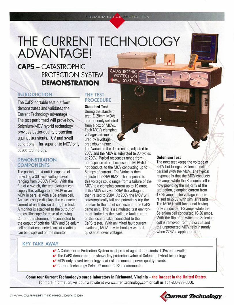
Selenium TestThe next test keeps the voltage at250V but brings a Selenium cell inparallel with the MDV. The typicalresponse is that the MOV conducts0.5 amps while the Selenium cell isnow providing the majority of theprotection, clamping current from17-25 amps. The voltage is thenraised to 275V with similar results.The MDV is still functional havingonly conducted 1-3 amps while theSelenium cell conducted 18-30 amps.With the flip of a switch the Seleniumcell is removed from the circuit andthe unprotected MOV fails instantlywhen 275V is applied to it.
THE TESTPROCEDUREStandard TestDuring the standardtest (2) 20mm MOVsare randomly selectedfrom a box of MOVs.Each MOVs clampingvoltages are measured by avoltagebreakdown tester.The Variac on the demo unit is adjusted to200V and the MOV is subjected to 30 cyclesat 200V. Typical responses range fromno response at all, because the MDV didnot conduct, to the MOV conducting up to5amps of current. The Variac is thenadjusted to 225V RMS. The response tothis voltage could range from a failure of theMDV to a clamping current up to 19 amps.If the MOV sUlVived 225V the voltage isthen raised to 250V At 250V the MOV willcatastrophically fail and potentially trip thebreaker to the outlet connected to the CaPSdemo unit. This is asimulated test environment limited by the available fault currentof the local breaker connected to theCaPS tester. With unlimited fault currentavailable, MOV only technology will failquicker at lower voltages.
INTRODUCTION
The CaPS portable test platform
demonstrates and validates theCurrent Technology advantage!
The test performed wi II prove how
Selenium/MOV hybrid technologyprovides better-quality protection
against transients, TOV and swell
conditions - far superior to MOV only
based technology.
DEMONSTRATIONCOMPONENTSThe portable test unit is capable ofproviding a 30 cycle voltage swellranging from 0-300V RMS. With theflip of a switch, the test platform cansupply this voltage to an MOV or anMOV in parallel with a Selenium cell.An oscilloscope displays the conductedcurrent of each device during the test.A monitor is attached to the output ofthe oscilloscope for ease of viewing.Current transformers are connected tothe output of both the MDV and Seleniumcell so that conducted current readingscan be displayed on the monitor.
THE CURRENT TECHNOLOGYADVANTAGEICAPS - CATASTROPHIC
PROTECTION SYSTEMDEMONSTRATION
KEY TAKE AWAYV" A Catastrophic Protection System must protect against transients, TOVs and swells.V" The CaPS demonstration shows key protection value of Selenium hybrid technology.V" MDV only based technology is at risk to common power quality events.V" Current Technology Select2~ meets CaPS requirements.
Come tour Current Technology's surge laboratory in Richmond, Virginia - the largest in the United States.For more information, visit our web site at wwwcurrenttechnology.com or call us at 1-800-238-5000.
WWW.CURRENTTECHNOLOGY.COM (Cuntmt Tec/moJogy.

FACILITY WIDE CATASTROPHIC PROTECTION SYSTEM
Part 1-General1.1 Description/Scope
A. The Catastrophic Protection System covered under this section includes all surge protection installed at theservice entrance and all distribution panels electrically downstream from the same service entrance.
B. A Catastrophic Protection System is a broad power quality protector capable of protecting against bothtransient surges under 100~Sec and temporary over voltages (TOV) and swells from 1OO~Sec to 2minutes.
C. Contractor shall provide all labor, materials, equipment and incidentals as shown, specified and required tofinish and install surge protection devises.
1.2 Quality AssuranceA. Reference Standard: Comply with the latest edition of the applicable provisions and recommendations of
the following, except as otherwise stated in this document:1. UL 1449 Second Edition 2005 Revision (effective 2/9/2007).2. UL 1283.3. ANSI/IEEE C62.41, Recommended Practice for Surge Voltages in Low-Voltage AC Power Circuits.4. ANSIIIEEE C62A5, Guide for Surge Testing for equipment connected to Low-Voltage AC Power
Circuits.5. ANSI/IEEE C62.34, Secondary Surge Arrestor.6. IEEE 1100 Emerald Book.7. NEMA LS-1, 1992-(R2000) Low Voltage Surge Protection Devises.8. National Fire Protection Association (NFPA 70: National Electrical Code).
1.3 Submittals/Quality Assurance - Submit the following:A. The Catastrophic Protection System must include shop drawings complete with all technical information,
unit dimensions, detailed installation instructions, maintenance manual, recommended replacement partslist and wiring configuration.
B. Copies of Manufacturer's catalog data, technical information and specifications on equipment proposed foruse.
C. Copies of documentation stating that the Surge Protection Device is listed from a Nationally RecognizedTesting Laboratory (NRTL) (UL, ETL, etc) and are tested and multi-listed to UL 1449 and UL 1283.
D. Copies of actual let through voltage data in the form of oscillograph results for both ANSIIIEEE C62A1Category C3 (combination wave) and B3 (Ring wave) tested in accordance with ANSI/IEEE C6245.
E. Copies of Noise Rejection testing as outlined in NEMA LS1-1992 (R2000) Section 3.11. Noise rejection isto be measured between 50kHZ and 100MHz verifying the devices noise attenuation. Must show multipleattenuation levels over a range of frequencies.
F. Copies of Surge Fuse Testing. Each unit shall be surge tested with fusing in series to verify that a transientof maximum surge current capacity/magnitude is fully suppressed without fuse failure, operation ordegradation per NEMA LS1-1992 (R2000) Section 3.9.
G. Copies of test reports from a recognized independent testing laboratory, capable of producing 200kA surgecurrent waveforms, verifying the suppressor components can survive published surge current rating onboth a per mode and per phase basis using the ANSI/IEEE C62A1 impulse waveform C3 (8 x 20microsecond, 20kV/1 OkA). Test data on an individual module is not acceptable.
H. Copy of warranty statement clearly establishing the terms and conditions to the building/facilityowner/operator.
Part 2-Products2.1 Approved Manufacturer: Service Entrance
A. Current Technology - Select2 or SL2 Series (voltage and surge current depending on specific application &location).
B. Approved equivalent.
2.2 Approved Manufacturer: Branch Panels, Distribution Systems, or Point of Use downstream of main serviceentrance.A. Current Technology - Select2, SL2, Select Compact or SLcB. Approved equivalent.
2.3 Manufactured Units/ Electrical RequirementsA. Refer to draWing for operating voltage, configuration and surge current capacity per mode for each location,
or you may list locations and information here.
Facility Wide Catastrophic Proteclion System -1- 9.20.07

B. Maximum Continuous Operating Voltage shall be greater than 115 percent of the nominal system operatingvoltage and in compiiance with test and evaluation procedures outlined in NEMA LS-1-1992 (R2000)paragraphs 2.2.6 and 3.6.
C. Unit shall have not more than 10% deterioration or degradation of the UL1449, Second Edition surgesuppression rating due to repeated surges. Unit shall have a monitoring option available to be able to testand determine the percentage of protection available at all times.
D. Protection Modes and NEMA LS1 1992 (R2000)/UL1449 SVR for grounded WYE/delta and High Leg Deltacircuits with voltages of (480Y/277), (208Y/120), (600Y/347). 3-Phase, 4 wire circuits, (120/240) splitphase shall be as follows:
System Mode B3 Rmgwave B3/C1 Comb. C3 Comb. Wave UL 1449Voltage Wave Second Edition120/240 L-N 300/350 400/450 625/725 400/400120/208 L-G 375/425 400/475 625/750 500/500
N-G 325/325 450/450 725/725 500/500L-L 375/475 750/825 975/1225 700/700
277/480 L-N 525/575 850/900 1125/1200 9001900L-G 8251850 850/875 1050/1200 1000/1000N-G 6751700 900/900 1200/1200 9001900L-L 6501725 1675/1700 1925/2175 150011500
E. Electrical Noise Filter- each unit shall include a high performance EMIIRFI noise rejection filter. Noiseattenuation for electric noise shall be as follows using the MIL-STD-220A insertion loss test method.1. 100 kHz at 44 db.2. All other frequencies should be 32 db or better.
F. The Catastrophic Protection System shall provide temporary over voltage and voltage swell protection tothe following:1. TOV - should be capable of surviving and continue to protect critical loads against multiple TOV events
(described as 200% nominal voltage by 8 mS.2. Swell- should be capable of protection against swells up to 180% nominal for 0.7 ohms load >18,000
events.G. Each fuse shall be individually sealed in a manner that eliminates cross arcing.H. Integral Disconnect Switch.
1. The device shall have an optional NEMA compliant safety interlocked integral disconnect switch with anexternally mounted metal manual operator.
2. The switch shall disconnect all ungrounded circuit conductors from the distribution system to enabletesting and maintenance without interruption to the facility's distribution system.
3. The switch shall be rated for 600Vac.4. The SPD device shall be tested to UL1449 Second Edition listed with the integral disconnect switch
and the UL1449 Second Edition Suppression Voltage Ratings shall be provided.5. The integral disconnect switch shall be capable of withstanding, without failure, the published maximum
surge current magnitude without failure or damage to the switch.I. Each unit shall provide the following features:
1. Phase Indicator lights, Form C dry contacts, counter and audible alarm.2. Field testable while installed.3. Measuring capability to indicate the percent protection available in SPD.
Part 3-Executionllnstallation3.1 Each unit shall be installed per Manufacturer's recommended installation and wiring practices, as show on the
drawing supplied.3.2 The UL 1449 Suppression Voltage Rating (SVR) shall be permanently affixed to the SPD unit.3.3 The SPD manufacturer's technician shall perform a system checkout and start-up in the field to assure proper
installation, operation and to initiate the warranty of the system. The technician will be required to do thefollowing:A. Verify clamp levels.B. Verify N-G connection.C. Record information to product signature card for each product installed.
Part 4-Product Warranty4.1 Warranty on defective material and workmanship shall be for 15 years.4.2 Copy of Warranty to be sent with submittal.
Facility Wide Catastrophic Protection System -2- 9.20.07

GE Digital EnergyPower Quality
Integral SPD's:A Safe Solution withBetter Performance
•

1 IntroductionThe increasing number af cammercially available
Surge Pratective Devices ISPD's) has pravided electricalsystem designers with a wide range af options to choose
fram. SPO's are currently defined by the 2008 NationalElectrical Code as Type 1iSurge Arrester) or Type 2 (TVSS!.
For the purpose of this paper, we will focus on SPO typescommonly referred to as Transient Voltage Surge Sup
pressors ITVSSI that are intended for use at locations
on the laad side of the primary overcurrent disconnect
or main breaker of the electrical distribution system.
Of the many model types, ratings and suppression
technologies available, there are essentially twodistinctive instollation methods that are frequentlyspecified for commercial and industrial opplications.
These are SPO's that are intended for either externalmounting or integral installation.
Externally mounted (also commonly referred to as"Wall-Mount" SPO'sl are availoble fram almost all major
manufocturers of SPO's. These devices are typicallyhoused in a dedicated enclosure and are intended to be
connected to the power distribution system vio electrical
conductors. These SPO's are terminated at a dedicatedbreaker, or in some instances directly to the phase
bus of the electrical panel. Externally mounted SPO's
ore designed to be installed by qualified electricolcontractors at the job site.
Integrally installed SPD's are offered by many electrical
distribution equipment manufacturers. Integral SPO'sare normolly mounted within the electrical gear and
shipped to the job site as a complete package. Integral
SPO's are factory installed and pre-wired to the electricalpanel bus, so in many cases there is no need for furtherinstallatian.
In recent years, a number of marketing publicationshave been released by monufacturers and proponents
of externally maunted SPO's about the potential hazardsassociated with placing these devices inside af elec
trical distribution equipment. The focus of these pub
lications are to create concerns about the possibilityof ancillary equipment damage that might occur in
the event of SPO failure. lit should be noted that SPDfoilure is most often the result of praduct misapplication
or sustained abnarmal phase voltage potentials!. Many
of these papers attempt to discourage the use of integrallyinstalled SPO's while citing IEEE or other industry recognized
standards as the authoritative basis for their position.
These documents, are carefully conceived, but typicolly fallwell shart of legitimacy due to the omission or misinterpretation of key information from the referenced
2
standards. In many instances, the case against integralSPO application is being made based on historical data
rather than taking into account the present status of
the industry and the regulations that are currently inplace to prevent the potentially destructive failure ofSPO's for all applications. The focus of this paper sholl
be to take a closer look at these standards, how they
relate to SPD's, and what has been done to remedy
the potentially damaging effects of a failing SPD.
Both externally mounted and integrally installed SPO's offer
a variety of options and features. There are advantages
and disadvantages for both design types. While exter
nally mounted SPO's offer a good solution for users thatwould like to add surge pratection to an existing elec
trical system, their installatian and performance can
be affected dramatically by enviranmental variables
such as limited panel access, limited wall space, orthe
level of experience that an installer has with such devices.
A knowledge of the characteristics of high-frequencytransient currents and the wiring techniques that must
be used to successfully convey these currents is neces
sary for the praper installation of any SPO. In contrast.integral SPO's are not restricted by panel access or
variations in installation. Since the SPO can be installed
very close to the conductor being pratected in an integral
mounting arrangement, the connecting lead length isoften much shorter than when connecting an externally
mounted SPD to the same conductor. This reduction inlead length contributes to impraved SPO voltage clamping
performance over that of the externally mounted installation and results in better surge protection (see "The
Influence of Cable Connections on TVSS Performance"
for more details)'- Equipment manufacturers who haveearned good reputations can usually be relied on to
employ persons who are trained and competent in thepraper wiring pracedures for installing SPOs within
their equipment. making the quality of the installationless of a factor with integrally installed SPOs. Some integral
devices are offered without a dedicated disconnectfeature which would require the panel to be powered
down in the rare instance that the SPO needs to beserviced or replaced. However, de-energizing theequipment may be preferred, even with SPO's equippedwith disconnects, when the SPO assembly is locatedadjacent to bare live parts.

2 Standards
IEEE 1100-2005 is an industry-recognized standard
that addresses recommended practices for the poweringand graunding of electronic equipment. While thisstandard is nat exclusive to 5PD's, there are relevant
sections with considerations for the application of suchdevices within the electrical distribution system. Section
8.4.2.5 states that SPD's "may be installed externallyor internally to the switchboard or panelboard." And that
"panelboards are available that contain integrally mountedSPD's that minimize the length of the SPD conductors,
thus optimizing the effectiveness of the device."
Additionally, IEEE 1100-2005 also cites IEEE preliminary
draft standard PC62.72 by stating, "there is concernthat failure of the SPD can cause collateral damage to
the switchboard or panelboards." However, readers ofIEEE 1100 might nat be aware that this statement was
not a direct quotation fram PC62.72. Instead it was an
interpretive comment made on section 14.1 of PC62.72that describes the failure mechanisms of Metal Oxide
Varistor (MOV) components that are commonly found
within most SPD assemblies.
PC62.72 has since been formally released as IEEEC62.72-2007, and is the IEEE guide standard for the
application of Surge Pratective Devices. The approvedstandard does nat, nor has ever contained any specific
language which would prohibit or warn against the
use of integral SPD assemblies.
Instead, IEEE C62.72-2007, Section 14.1 cautions that
MOV's might expel hot metal fragments, conductiveionized gases, or canductive smoke/soot upon reaching
a destructive thermal runaway condition. Of greaterimportance, C62.72 also advises that manufacturers will
anticipate possible MOV failure and lessen or eliminate
these potentially damaging effects using a variety ofmethods. These methods can include, but are not limited
to, containment of the failing camponents by a fortifiedencasement, the addition of current limiting fusing, em
ploying thermal cutoffs, using non-flammable or flamequenching material/media, or any cambination thereof.
3 MOV Design Considerations
Because of the many ways to prevent or contain thepotentially damaging effects of MOV's, it is unlikely that
any two SPD manufacturers will employ identical designapproaches. Thus, it is important to realize that theseverity of failure is dependant upon the SPD design anddestructive failure prevention techniques and not the
location of the SPD installation. An effectively designedSPD should nat fail in a manner that compramises the
integrity of surraunding electrical equipment. regardlessof integral or external design types. All major manu-
facturers within the surge protection industry should beaware of the potential for catastrophic failure of MOV'sand should design for each application accordingly.
MOV's will eventually reach an end-of-Iife condition
should the power system voltage elevate beyond theMaximum Continuous Operating Voltage (MCOVI rating
of the SPD. MOV degradation can also lead to a permanentfailure condition by gradually reducing the voltage
clamping characteristic of the MOV until the clamping
level eventually coincides with the normal system voltage.While degradation due to excessive surge energy remains
a possibility within lower surge energy rated designs,
it is nat considered a normal occurrence in the majorityof today's high-energy SPD praducts.
Regardless of the cause of MOV failure, the end resultwill be the same. When an extended avervoltage ispresent, or if the MOV degrades below the nominal
operating voltage of the electrical power system, the
MOV will attempt to "clamp" the system phase voltage.The MOV begins to cycle with the power frequency,
initially "clipping" the voltage peaks of AC sinewave.The MOV attempts to dissipate the residual current,
resulting in a rapid heating of the MOV body. This initialcycling/clipping condition of an MOV, attempting to
absorb the overvoltage energy, begins the end-of-lifestage of the MOV. This pracess is known as "thermal
runaway". When the MOV can no longer dissipate this
energy, it will typically fail at a random location an theMOV body. This location is sometimes referred to as
the "punch-thraugh" site where the low impedancebreakdown and subsequent shorting of the failing
MOV develops. Once the MOV reaches a law resistive
state, it can rapidly become a fragmentation and/or firehazard if not immediately removed fram the electrical
system fault current path. The level of available systemfault current will then drive the subsequent destructive
energy release fram the MOV.
As stated in IEEE C62.72, section 14.1, SPD manufacturers
employ various techniques in an attempt to limit thedamage caused by a failing MOV. For example, designs
that include a combination of current limiting fuses and
thermal cutoffs rely on the current limiting fuses to interrupt high fault currents and the thermal cutoffs tointerrupt low fault currents by opening as a result ofradiant heat emitted fram the body of the failing MOV.
However, coordination of fault interruption at intermediatefault current levels can present a significant problemfor SPD design engineers. Thermal cutoffs are only good
for limited levels of available current and can only reactif the MOV can radiate enough heat directly at the cutoff
during the thermal runaway cycle. The higher theavailable fault current. the more rapidly the failing MOV
3

will be driven into a low resistive state. In most cases,this happens much too fast for even the closest proximity
thermal cutoffs to react. And once the MOV has shorted,the initial energy release from the MOV will be concentroted
at the location on the MOV surface where the short hasoriginated. After this sequence occurs, the thermal cut
offs become ineffective. And if the fault current potentialis not significant enough to open the primary current
limiting fuse, the SPD could remain in a low resistive state
with on unstable MOV that continues to emit intenseenergy in the form of fiome, molten material, smoke, etc.
If only limited or intermediate system fault conditions
are present, or if the SPD is not designed to effectively
deal with fault currents at less than the maximum short
circuit rating of the SPD, it is easy see how certain SPDdesigns could couse damage to the surrounding electricol
equipment once the SPD housing has been breached
by a foiling MOV.
4 Safety Testing
UL1449 is the industry-recognized safety standard for
Surge Protective Devices. During reviews of the UL 1449
standard in 2005, the UL Standards Technical Panelagreed that certain "blind spots" still existed within the
abnormal avervoltoge/foult current testing programthat is defined within the standard.
As a result, UL 1449 was revised to incorporote additional
requirements for abnormal overvoltoge testing to beapplied with available intermediate fault currents of
10, 100, sao and 1000 amperes. These new testinglevels were mode in addition to the maximum short
circuit current and limited current testing levels thatwere introduced in the initial release of UL 1449 2'dedition in 1996. The addition of these new testing levels
are intended to address conditions that SPD's are likelyto be exposed to under a more extensive ronge of fault
current potentials that exist within typical power systems.
Many times, SPD's are installed on secondary powersystems with power transformers or other power
generation sources that cannot produce the maximumfault current potentials the SPD is rated for. As on example,
on SPD that has been rated for use on power systems
with a short circuit fault current potential of 200kA willbe connected to a power system that is only capableof delivering a few thousand short circuit amperes.Prior to the addition of the new testing requirements,
UL did not evaluate the SPD for safe current interruptionat these lower, fault potentials. The new intermediate
~W imagination at work
fault testing levels would reveal the vulnerability of manySPD designs that did not have full current limiting coordination across ranges that are much lower than the
tested maximum short circuit interrupt levels.
During the UL test sequence for each specified fault
current, the SPD is purposely driven into a failure condition
by applying twice the nominal phose voltage that theSPD is designed for. In order to obtain a passing grode,the SPD cannot foil with any form of cotastrophic results
that would include emission of flame, molten metal,
glowing or flaming particles through any openings,charring, glowing, or flaming of the supporting surface,
tissue paper, or cheesecloth, ignition of the enclosure,
creation of any openings in the enclosure that resultin accessibility of live parts or loss of structural integrity.
The mandatory dote for UL certification using the intermediate level fault current testing revisions of UL 1449
was February 9, 2007. SPD's that are manufactured
after this dote will not have authorization to apply the
UL mark unless UL witness testing has been performedon each of the manufacturer's representative SPD models
and voltage types and are found to be in compliance.
These recent and significant testing updates to the UL1449 standard should help to assure those who specifyand purchase UL 1449 certified SPD's that the SPD's will
not become a fire or fragmentation hazard, nor couse
damage to surrounding gear, when the MOV's or other
suppression components foil.
5 Conclusion
Integral SPD's provide on excellent choice for newconstruction applications by eliminating installationvariables, saving wall space and reducing the performance degroding effects of SPD connecting lead length.Many proponents and manufactures of wall mount onlytype SPD's will argue that integrally mounted designsare unsafe, or will couse substantial collateral damageupon foiling while often citing incomplete or misinterpreted passages from various standards and historicaldocuments as the basis. However, due to very recentchanges in safety testing standards, SPD devices thatare certified by UL to the latest revisions of UL 1449will provide a safe and reliable solution for applicationswhere the SPD is factory installed within electrical distribution equipment.
1 The Innuence of Coble Connections on TVSS Performance Marshall, E.; Honder:Valdes, M.; Britton, J.: Jones. 1: Whitehead. J.; Mcintyre, B. Industrial and CommercialPower Systems Technical Conference. 200S IEEE Volume, Issue. 8-12 May 200SPagels): 212-217
GE Digital Energy - Power Quality701 E22nd Street, lombord,lL 60148 USA
8006371738 www.gedigitolenergy.com/tvsswww.getvss.com
Information subject 10 change without notice. Please verify 011 details with GE.OET-661 1121081 lO 2008 General Electric Company All Rights Reserved
'-