Transient Hydroelastic Analysis of Surface-Piercing Propellers
6
Proceedings of the 7 th International Symposium on Cavitation CAV2009 – Paper No. 59 August 17-22, 2009, Ann Arbor, Michigan, USA 1 Transient Hydroelastic Analysis of Surface-Piercing Propellers Yin Lu Young Dept. of Naval Architecture & Marine Engineering University of Michigan Ann Arbor, MI, USA Brant R. Savander Maritime Research Associates Ann Arbor, MI, USA ABSTRACT A coupled boundary element method – finite element method (BEM-FEM) is presented for the transient hydroelastic analysis of surface-piercing propellers (SPPs). The method is used to help the design and analysis of three different size SPPs that deliver a constant advance speed of 25.72 m/s (50 knots). Numerical validation studies are shown. The mean and unsteady responses of the three SPPs are presented. Finally, limitations of the BEM-FEM method are discussed. INTRODUCTION It is well known that a properly designed SPP can deliver higher fuel-efficiency for high-speed vessels than conventional fully submerged propellers or water-jets. The high efficiency of a SPP is primarily attributed to 1) the reduction of appendage drag by elevating most of the propeller assembly (e.g. shafts, struts, hub, etc.) above the water surface, and 2) the significant reduction of water drag by drawing air from the surface. Although SPPs can provide higher fuel efficiency, particularly for lightly-loaded high-speed vessels, they are not commonly employed compared to water-jets because of 1) reduced efficiency when operating in low-speed conditions due to high drag forces associated with the blunt blade trailing edge and difficulty in ensuring fully ventilated cavities, 2) high levels of blade stress, especially at the blade entry phase where impact forces are mostly absorbed by the thin blade leading edge, and 3) fatigue and vibration issues due to the cyclic loading and unloading of the blades. These problems are often a result of improper design of the propulsion system due to the lack of a reliable design and analysis methods and the scarcity of systematic performance data. Currently available analysis methodologies for SPPs can be generally categorized into blade element and lifting line methods, vortex-lattice methods (VLMs), boundary element methods (BEMs), and computational fluid dynamic methods (CFDs). A brief summary of representative models found in literature, as well as discussions about the capabilities and limitation of each of the four approaches are presented in [1]. For potential based methods, BEMs are preferred over blade element, lifting line, and vortex-lattice methods because of their ability to predict complex three-dimensional (3-D) flow around the leading edge and tips of propeller blades, and inherently account for the effects of nonlinear thickness-loading coupling. In particular, the BEM presented in [2,3] have been found to be an efficient computational tool to predict the mean and unsteady blade loads, as well as ventilation patterns, of SPPs in partially-ventilated, transitional, and fully-ventilated flow regimes assuming the blades to be rigid, the air cavities vent to the free surface, and the infinite Froude number assumption to be valid. However, for cases where viscous effects dominate, or for challenging flow conditions that involve complex free surface geometry, finite Froude number effects, large hub submersion, and large shaft and yaw angles, CFD methods such as Reynolds Averaged Navier Stokes (RANS) simulations are needed. The primary drawback of the RANS approach for SPP analysis is the required computational resources to perform the calculations in a time frame reasonable for the design process. Nevertheless, almost all of the available analysis methods are limited to hydrodynamic analysis. For large-scale SPPs, an important concern is the structural dynamic performance because of the high stresses imposed on the blades and the potential susceptibility of the blades to resonance and fatigue failures. Hence, the objectives of this work are to 1) present a coupled BEM-FEM for the transient hydroelastic analysis of SPPs, and 2) use the method to assist the design and analysis of three SPPs to accommodate different size Surface Effect Ships (SESs) that can deliver a constant speed of 25.72 m/s (50 knots). TRANSIENT HYDROELASTIC ANALYSIS OF SURFACE-PIERCING PROPELLERS In this work, a coupled BEM-FEM is used to simulate the transient hydroelastic response of SPPs. The method was initially developed for the analysis of rigid metallic and flexible composite marine propellers, and is extended here for the analysis of SPPS. The BEM solves for the perturbation velocity induced by the propeller. It assumes the total inflow velocity to be composed of the effective inflow velocity and the perturbation potential velocity induced by the propeller. The effective inflow velocity, defined in the non-inertial, rotating, blade-fixed coordinates system, (x,y,z), represents the velocity distribution
Transcript of Transient Hydroelastic Analysis of Surface-Piercing Propellers
Proceedings of the 7th International Symposium on Cavitation CAV2009 – Paper No. 59
August 17-22, 2009, Ann Arbor, Michigan, USA
1
Transient Hydroelastic Analysis of Surface-Piercing Propellers
Yin Lu Young Dept. of Naval Architecture & Marine Engineering
University of Michigan Ann Arbor, MI, USA
Brant R. Savander Maritime Research Associates
Ann Arbor, MI, USA
ABSTRACT
A coupled boundary element method – finite element method (BEM-FEM) is presented for the transient hydroelastic analysis of surface-piercing propellers (SPPs). The method is used to help the design and analysis of three different size SPPs that deliver a constant advance speed of 25.72 m/s (50 knots). Numerical validation studies are shown. The mean and unsteady responses of the three SPPs are presented. Finally, limitations of the BEM-FEM method are discussed.
INTRODUCTION It is well known that a properly designed SPP can deliver
higher fuel-efficiency for high-speed vessels than conventional fully submerged propellers or water-jets. The high efficiency of a SPP is primarily attributed to 1) the reduction of appendage drag by elevating most of the propeller assembly (e.g. shafts, struts, hub, etc.) above the water surface, and 2) the significant reduction of water drag by drawing air from the surface. Although SPPs can provide higher fuel efficiency, particularly for lightly-loaded high-speed vessels, they are not commonly employed compared to water-jets because of 1) reduced efficiency when operating in low-speed conditions due to high drag forces associated with the blunt blade trailing edge and difficulty in ensuring fully ventilated cavities, 2) high levels of blade stress, especially at the blade entry phase where impact forces are mostly absorbed by the thin blade leading edge, and 3) fatigue and vibration issues due to the cyclic loading and unloading of the blades. These problems are often a result of improper design of the propulsion system due to the lack of a reliable design and analysis methods and the scarcity of systematic performance data.
Currently available analysis methodologies for SPPs can be generally categorized into blade element and lifting line methods, vortex-lattice methods (VLMs), boundary element methods (BEMs), and computational fluid dynamic methods (CFDs). A brief summary of representative models found in literature, as well as discussions about the capabilities and limitation of each of the four approaches are presented in [1].
For potential based methods, BEMs are preferred over blade element, lifting line, and vortex-lattice methods because of their ability to predict complex three-dimensional (3-D) flow
around the leading edge and tips of propeller blades, and inherently account for the effects of nonlinear thickness-loading coupling. In particular, the BEM presented in [2,3] have been found to be an efficient computational tool to predict the mean and unsteady blade loads, as well as ventilation patterns, of SPPs in partially-ventilated, transitional, and fully-ventilated flow regimes assuming the blades to be rigid, the air cavities vent to the free surface, and the infinite Froude number assumption to be valid. However, for cases where viscous effects dominate, or for challenging flow conditions that involve complex free surface geometry, finite Froude number effects, large hub submersion, and large shaft and yaw angles, CFD methods such as Reynolds Averaged Navier Stokes (RANS) simulations are needed. The primary drawback of the RANS approach for SPP analysis is the required computational resources to perform the calculations in a time frame reasonable for the design process. Nevertheless, almost all of the available analysis methods are limited to hydrodynamic analysis. For large-scale SPPs, an important concern is the structural dynamic performance because of the high stresses imposed on the blades and the potential susceptibility of the blades to resonance and fatigue failures. Hence, the objectives of this work are to 1) present a coupled BEM-FEM for the transient hydroelastic analysis of SPPs, and 2) use the method to assist the design and analysis of three SPPs to accommodate different size Surface Effect Ships (SESs) that can deliver a constant speed of 25.72 m/s (50 knots).
TRANSIENT HYDROELASTIC ANALYSIS OF SURFACE-PIERCING PROPELLERS
In this work, a coupled BEM-FEM is used to simulate the transient hydroelastic response of SPPs. The method was initially developed for the analysis of rigid metallic and flexible composite marine propellers, and is extended here for the analysis of SPPS.
The BEM solves for the perturbation velocity induced by the propeller. It assumes the total inflow velocity to be composed of the effective inflow velocity and the perturbation potential velocity induced by the propeller. The effective inflow velocity, defined in the non-inertial, rotating, blade-fixed coordinates system, (x,y,z), represents the velocity distribution
2
at the rotor plane in absence of the rotor, the rotor's angular velocity, and the vortical interactions between the rotor and the inflow. The x-axis is defined to be co-linear with the axis of rotation and is positive in the downstream direction; the y-axis is co-linear with the pitch change axis with the positive direction pointing toward the blade tip. In the ship-fixed coordinates system, (X,Y,Z), the X-axis coincides with the x-axis, and the Y-axis is the vertical coordinate and is defined positive in the direction opposite to gravity. The blade angle defined with respect to the ship-fixed coordinates system is denoted with s=tan-1(Z/Y)=b-t, where b=tan-1(z/y), n, and n is the angular velocity of the propeller in revolutions per second.
Assuming the effective inflow velocity to be known via numerical simulations or experimental measurements, the fluid problem reduces to a mixed, moving boundary value problem governed by the Laplace equation for the perturbation velocity potential. The flow is assumed to be incompressible, inviscid, and irrotational. For SPPs, the cavities are assumed to be filled with air and vent to the atmosphere. On the ventilated cavity surface, the pressure is assumed to be constant and equal to the atmospheric pressure. On the wetted blade surface, the flow is required to be tangent to the blade surface. The negative image method is applied to account for the effect of the free surface; it assumes the Froude number to be large enough (i.e. Fr=[n2D/g]1/2>4, where g is the gravitational acceleration and D is the propeller diameter) such that inertial effect dominates and the linearized free surface boundary conditions to be valid. The detachment locations of the ventilated cavities on the suction sides of the blades are searched for iteratively by applying a modified smooth cavity detachment condition [2,3]; the pressure sides of the blades are assumed to be fully wetted. The wake is aligned with the inflow velocity corresponding to the blade at the fully submerged vertical position using an iterative lifting surface method developed by [4].
The mixed boundary value problem is solved using a lower-order potential-based BEM by applying Green’s third identity in the time domain. Viscous effects are considered by applying a constant friction coefficient, which is a function of the Reynolds number, over the wetted blade surfaces. The thicknesses of the cavities on the blade and wake surfaces are determined by applying the flow tangency condition on the cavity surfaces. Details of the mathematical formulation, numerical implementation, as well as numerical and experimental validation studies of the BEM model for transient hydrodynamic analysis of SPPs can be found in [2,3].
The effects of the fluid-structure interaction are considered by linearly decomposing the perturbation velocity potential induced by the propeller into (1) a part due to rigid body rotation and (2) a part due to elastic body deformation. Application of the pressure and velocity compatibility conditions on the deforming blade surfaces provide a relation for the transient hydroelastic force induced by elastic body deformation in terms of an added mass matrix times the solid nodal acceleration vector, and a hydrodynamic damping matrix times the solid nodal velocity vector [5,6]. The added mass matrix and hydrodynamic damping matrix are superimposed on to the structural mass matrix and structural damping matrix, respectively, via user-defined hydroelastic elements [5,6]. The
commercial FEM solver, ABAQUS/Standard [7] is used to solve the resulting equation of motion for the blades in the time domain in the rotating blade-fixed coordinates system. The blades are assumed to be fixed at the roots (i.e. rigidly attached to the hub) and three layers of quadratic continuum elements across the blade thickness are used to represent the blades. The effects of nonlinear elastic blade formations are considered by iterating between the BEM and FEM solvers. Details of the mathematical formulation, numerical implementation, as well as numerical and experimental validation studies of the BEM-FEM model can found in [5,6].
PROPELLER DESIGN AND FLOW CONDITION To demonstrate the method, results are shown for three
SPPs for different size SES that can deliver a constant advance speed of V=25.72 m/s (50 knots). The propellers are assumed to be powered by General Electric (GE) LM2500, LM1600, and LM500 gas turbines with break powers of 25 MW, 16 MW, and 5 MW, respectively.
The blade section design procedure follows the guidance provided by [8,9]. The chord-wise location of the maximum camber is biased toward the blade trailing edge to minimize cavity drag. The pitch and camber distributions were determined by minimizing back cavity thickness while avoiding face cavitation. The blade area and number were also selected to minimize face cavitation exposure. Notice that the design propeller angular velocity (n) must be kept high enough to maintain ventilation of the back cavities. Otherwise, hydrostatic pressure gradient associated with varying blade submergence can tend to collapse the ventilated back cavity and cause a loss in efficiency. Hence, a balance is needed when determining the optimal D and n to achieve the maximum efficiency.
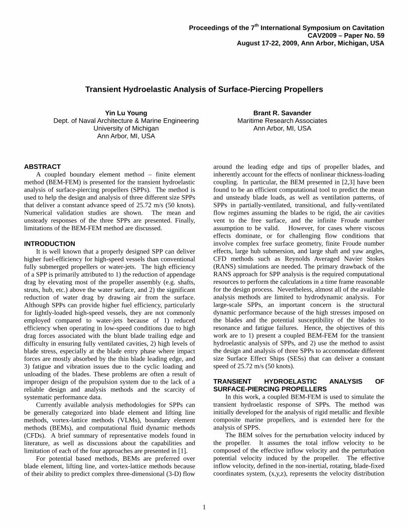
The final propeller geometry and design flow condition for the three SPPs are shown in Fig. 1 and Table 1, respectively.
Figure 1: Geometry of the three propellers LM2500 (left), LM1600 (middle), LM500 (right). SPP Name
D (m/in)
Ae/Ao n (rpm)
J=V/nD
FnD
LM2500 2.438/96 0.78 1006 0.629 8.36 LM1600 2.134/84 0.73 1097 0.659 8.53 LM500 1.524/60 0.73 1237 0.819 8.13
Table 1: Design specifications of the three SPPs. The design speed for all three SPPs is 25.72 m/s (50 knots).
3
NUMERICAL VALIDATION STUDIES WITH FLUENT – FULLY SUBMERGED OPERATIONS
To validate the BEM predictions, the results are compared with FLUENT [10], a commercial CFD solver. The propellers are assumed to be fully submerged (in super-cavitating or SCP mode) and operating in axi-symmetric flow. The shaft axis (ho) is assumed to be at 1.07 m (3.5 ft) from the free surface. The corresponding cavitation number n=(Po-Pv)/(0.5n2D2)=0.123, 0.135 and 0.208 for propellers LM2500, LM1600, and LM500, respectively. Po=Patm+gho is the upstream hydrostatic pressure at the shaft axis. Patm=101.3 kPa and Pv=6000 Pa are the atmospheric pressure and saturated vapor pressure of water, respectively.
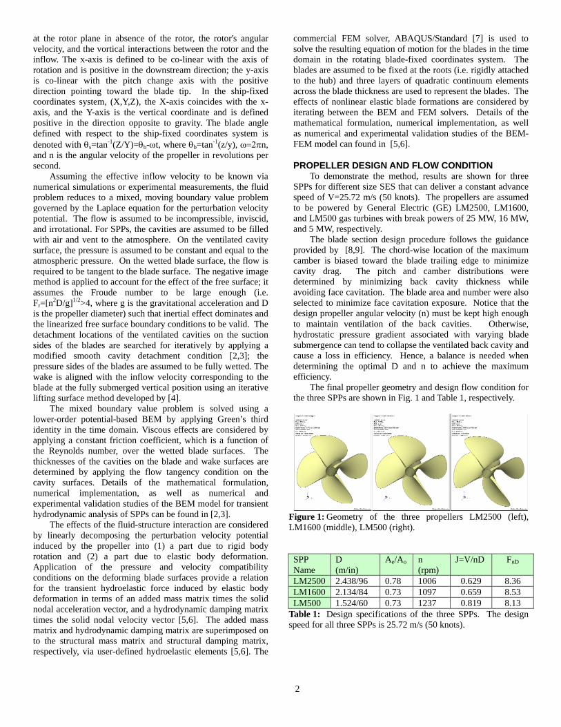
FLUENT uses a cell-centered finite volume method to solve the RANS system of equations in a control volume formulation. The Reynolds stress tensor was modeled using the SST form of the turbulence model described in [11,12], and the Schnerr and Sauer [13] cavitation model was used. The SCP computational domain topology and the applied boundary conditions are shown in Fig. 2. The total number of polyhedral elements in the domain was 270,000. The boundary layer resolution was adjusted until the y+ values on the majority of the blade surface were in the range of 50< y+<300. The analyses were conducted with a steady, moving reference frame formulation.
Figure 2: FLUENT model setup and applied boundary conditions for fully submerged SCP-mode analyses of the three SPPs.
SPP Name
BEM SCP results RANS SCP results T (kN) PD (kW) T (kN) PD (kW)
LM2500 854 36920 850 36698 LM1600 639 26545 594 25454 LM500 200 7863 200 8085
Table 2: Comparison of the thrust (T) and power demand (PD) predicted by the BEM and RANS models for the three SPPs in fully submerged SCP-mode operation at the design flow condition.
The computation time for each (J, n) combination was approximately few minutes on a single processor for the BEM calculations (which uses 60 chordwise by 20 spanwise panels
on the blade surface) and three hours on a 24-core HP Linux cluster for the RANS calculations.
As shown in Table 2, both the BEM and RANS solvers yield similar thrust (T) and power demand (PD=Q where Q is the torque) predictions for the three SPPs in fully submerged SCP-mode operations at the design flow condition. The predicted cavitation patterns were also similar, as demonstrated in Fig. 3 for propeller LM2500 at J=0.73 and v=n/J
2=0.35. Additional validation studies for other flow conditions, and additional numerical validation studies with a 3-D vortex-lattice method are given in [1]. The results suggest that the BEM method is able to efficiently and reliably predict the hydrodynamic performance and cavitation pattern of the propellers in partially-cavitating and super-cavitating conditions.
Figure 3: Comparisons of the predicted cavitation patterns for propeller LM2500 operating at fully submerged (SCP-mode) conditions with J=0.73 and v=n/J
2=0.35. Axi-symmetric inflow.
TRANSIENT HYDRODYNAMIC PERFORMANCE – PARTIALLY SUBMERGED OPERATIONS
RANS analysis of the unsteady performance of SPPs in partially submerged operations is very expensive due to the need to simulate the dynamics of the water and air flow surrounding the propeller, and the need to track the motion of the free surface and the rotating blades. Hence, only numerical predictions from the coupled BEM-FEM solver are shown in this section.
In all of the unsteady SPP analyses, the water line is assumed to be located just beneath the base of each hub. The resulting blade tip immersion ratios (I= htip/D where htip is the vertical distance between the free surface and the maximum depth of the blade tip) for propellers LM2500, LM1600, and LM500 are 0.4323, 0.4368, and 0.4375, respectively.
Comparisons of the predicted mean thrust (T), power demand (PD), and efficiency (=T*V/PD) of the three SPPs are shown in Table 3. The efficiency decreases with increasing power demand because of the increase in disc loading. Hence, propeller LM2500 has the lowest efficiency compared to LM1600 and LM500.

4
SPP Name T (kN) PD (kW) LM2500 346 14386 0.620 LM1600 248 10080 0.632 LM500 69 2613 0.680
Table 3: BEM predictions of the mean thrust (T), power demand (PD), and efficiency (=T*V/PD) of the three SPPs operating in partially submerged conditions at the design J with the waterline immediately below the base of the hub.
A quick comparison of the results shown in Tables 2 and 3 reveals that the mean thrust and power demand obtained via unsteady SPP-mode analysis is less than that of the quasi-steady SCP-mode results scaled by the blade tip immersion ratio (I). Understanding this difference crucial when designing SPPs to meet the specific load displacement requirements.
To investigate the transient hydroelastic performance of the propellers, the results are shown for the most heavily loaded propeller, LM2500. The predicted ventilation patterns and pressure contours for propeller LM2500 at the design condition (J=0.63 and I=0.4323) are shown in the left side of Fig. 4. The propeller is operating in the fully ventilated flow regime, where continuous, stable, ventilated cavities form near the blade leading edge on the suction side of each blade and vent to the atmosphere. Consequently, the pressure on the suction side of the blade is constant and equal to the atmospheric pressure, and hence not shown in Fig. 4
Figure 4: Predicted ventilated patterns (upper left), pressure contours (lower left), and individual blade force (upper right) and moment (lower right) coefficients in blade-fixed coordinates for propeller LM2500. J=0.63 and I=0.4323.
The variation of the individual blade force (KFx, KFy, & KFz) and moment (KMx, KMy, and KMz) coefficients in the blade-fixed coordinates (x,y,z) with the blade angle s is shown On the right side of Fig. 4. Notice that the blade force and moment coefficients are normalized by n2D4 and n2D5, respectively. The blade forces (and moments) are zero in the in-air phase, s<72o and s>300o. The magnitude of the loads increase as the blade submergence increases until the blade reach the deepest position, s=216o, and then the loads decrease as the blade exits. The submerged area and the center of force change with blade angle. During the blade-entry phase, the center of force
acts toward the blade leading edge and the root; during the blade-exit phase, the center of force acts toward the blade trailing edge and the tip. Consequently, the time-history of the blade loads are not symmetric with respect to the vertical plane, and high side forces and moments are generated because of the unbalanced loads between the blades.
Figure 5: Predicted dynamic blade and shaft force coefficients in ship-fixed coordinates for propeller LM2500. J=0.63 and I=0.4323.
Figure 6: Predicted dynamic blade and shaft moment coefficients in ship-fixed coordinates for propeller LM2500. J=0.63 and I=0.4323.
5
The individual blade and shaft force (KFX, KFY, & KFZ) and moment (KMX, KMY, & KMZ) coefficients in the ship-fixed coordinates (X, Y, Z) are shown in Figs. 5 and 6. The net vertical shaft force (KFY) is very small because the individual vertical blade force shifts from positive (upwards) to negative (downwards) when moving from the blade-entry phase to the blade-exit phase. However, the net horizontal shaft force (KFZ) is not small because the individual horizontal blade force is always negative (towards the starboard) throughout the flow cycle. Consequently, the net horizontal shaft force is approximately 40% of the axial shaft force (KFX). Similarly, the resultant vertical shaft moment coefficients (KMY) are small because cancellation effects caused by the four blades, but the resultant horizontal shaft moment coefficients (KMZ) are very large. In fact, the horizontal shaft moments are approximately 1.7 times the axial shaft moment (KMX).
TRANSIENT HYDROELASTIC PERFORMANCE – PARTIALLY SUBMERGED OPERATIONS
In addition to the hydrodynamic performance, it is also important to understand the structural dynamic performance to investigate the potential susceptibility to material failure and/or structural instability caused by resonant vibration. Results are shown here for the largest SPP, LM2500. The blades are assumed to be made of a high strength, precipitation hardenable iron-chromium-nickel-copper alloy with high corrosion resistant, type CB7Cu. The assumed material properties are as follows: solid density s=7750 kg/m3, Young's modulus E=196.5 GPa, Poisson's ratio =0.3, and tensile yield strength y=1.17 GPa.
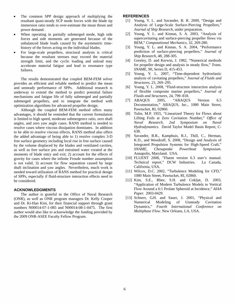
Figure 7: Predicted variation of the natural frequencies with blade angle for propeller LM2500. I=0.4323.
The predicted variation of the natural frequencies with blade angles for propeller LM2500 with a blade tip immersion ratio of I=0.4323 are shown in Fig. 7. The natural frequencies decrease as the blade moves from the in-air phase to in-water phase because of increasing added mass effect, and then increases as the blade moves from the in-water phase back to the in air-phase. For the first mode, the natural frequency changes from 110 Hz during the in-air phase to 65 Hz at the deepest blade submergence angle, s=216o. At the design flow
condition, the primary excitation frequency on the blades is n=1006 rpm=16.8 Hz, which is well below 65 Hz. Hence, the blades are not likely to be subject to resonance failure.
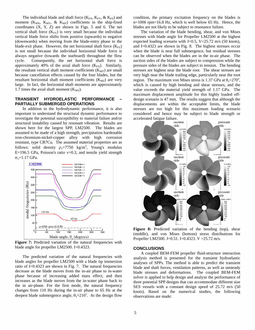
The variation of the blade bending, shear, and von Mises stresses with blade angle for Propeller LM2500 at the highest expected loading scenario with J=0.5, V=25.72 m/s (50 knots), and I=0.4323 are shown in Fig. 8. The highest stresses occur when the blade is near full submergence, but residual stresses can be observed when the blades are in the in-air phase. The suction sides of the blades are subject to compression while the pressure sides of the blades are subject to tension. The bending stresses are highest near the blade root. The shear stresses are very high near the blade trailing edge, particularly near the root region. The maximum von Mises stress is 1.37 GPa at s=270o, which is caused by high bending and shear stresses, and the value exceeds the material yield strength of 1.17 GPa. The maximum displacement amplitude for this highly loaded off-design scenario is 47 mm. The results suggest that although the displacements are within the acceptable limits, the blade stresses are too high for this maximum loading scenario considered and hence may be subject to blade strength or accelerated fatigue failure.
Figure 8: Predicted variation of the bending (top), shear (middle), and von Mises (bottom) stress distributions for Propeller LM2500. J=0.51. I=0.4323. V =25.72 m/s.
CONCLUSIONS A coupled BEM-FEM propeller fluid-structure interaction
analysis method is presented for the transient hydroelastic analyses of SPPs. The method is able to predict the transient blade and shaft forces, ventilation patterns, as well as unsteady blade stresses and deformations. The coupled BEM-FEM solver is applied to help design and analyze the performance of three potential SPP designs that can accommodate different size SES vessels with a constant design speed of 25.72 m/s (50 knots). Based on the numerical studies, the following observations are made:
6
The common SPP design approach of multiplying the resultant quasi-steady SCP mode forces with the blade tip immersion ratio tends to over-estimate the mean thrust and power demand.
When operating in partially submerged mode, high side forces and side moments are generated because of the unbalanced blade loads caused by the asymmetric time-history of the forces acting on the individual blades.
For large-scale propellers, structural analysis is critical because the resultant stresses may exceed the material strength limit, and the cyclic loading and unload may accelerate material fatigue and lead to resonance type failures.
The results demonstrated that coupled BEM-FEM solver
provides an efficient and reliable method to predict the mean and unsteady performance of SPPs. Additional research is underway to extend the method to predict potential failure mechanisms and fatigue life of fully submerged and partially submerged propellers, and to integrate the method with optimization algorithms for advanced propeller design.
Although the coupled BEM-FEM method offers many advantages, it should be reminded that the current formulation is limited to high speed, moderate submergence ratio, zero shaft angles, and zero yaw angle cases. RANS method is needed to resolve cases where viscous dissipation dominates. In addition to be able to resolve viscous effects, RANS method also offers the added advantage of being able to 1) resolve complex 3-D free surface geometry including local rise in free surface caused by the volume displaced by the blades and ventilated cavities, as well as free surface jets and entrained water created at the moments of blade entry and exit; 2) account for the effects of gravity for cases where the infinite Froude number assumption is not valid, 3) account for flow separation caused by large shaft inclination and yaw angles. Nevertheless, much work is needed toward utilization of RANS method for practical design of SPPs, especially if fluid-structure interaction effects need to be considered.
ACKNOWLEDGMENTS The author is grateful to the Office of Naval Research
(ONR), as well as ONR program managers Dr. Kelly Cooper and Dr. Ki-Han Kim, for their financial support through grant numbers N00014-07-1-085 and N00014-08-1-0475. The first author would also like to acknowledge the funding provided by the 2009 ONR-ASEE Faculty Fellow Program.
REFERENCES [1] Young, Y. L. and Savander, B. R. 2009, “Design and
Analysis of Large-Scale Surface-Piercing Propellers,” Journal of Ship Research, under preparation.
[2] Young, Y. L. and Kinnas, S. A. 2003, “Analysis of supercavitating and surface-piercing propeller flows via BEM,” Computational Mechanics, 32, 269-280.
[3] Young, Y. L. and Kinnas, S. A. 2004, “Performance prediction of surface-piercing propellers,” Journal of Ship Research, 48, 288-305.
[4] Greeley, D. and Kerwin, J. 1982, “Numerical methods for propeller design and analysis in steady flow,” Trans. SNAME, 90, Series D, 415-453.
[5] Young, Y. L. 2007, “Time-dependent hydroelastic analysis of cavitating propellers,” Journal of Fluids and Structures, 23, 269–295.
[6] Young, Y. L. 2008, “Fluid-structure interaction analysis of flexible composite marine propellers,” Journal of Fluids and Structures, 24, 799–818.
[7] ABAQUS 2005, “ABAQUS Version 6.5 Documentation,” ABAQUS, Inc., 1080 Main Street, Pawtucket, RI, 02860.
[8] Tulin, M.P. 1955, “Linearized Theory for Flows about Lifting Foils at Zero Cavitation Number,” Office of Naval Research, 2nd Symposium on Naval Hydrodynamics. David Taylor Model Basin Report, C-638.
[9] Savander, B.R., Kamphuis, R.J., Thill, C., Herman, K.D., and Woodruff, S. 2008, “Design and Analysis of Integrated Propulsion Systems for High-Speed Craft,” SNAME, Chesapeake Powerboat Symposium. Annapolis, Maryland. USA.
[10] FLUENT 2008, “Fluent version 6.3 user’s manual. Technical report,” DCW Industries. La Canada, California, USA.
[11] Wilcox, D.C. 2002, “Turbulence Modeling for CFD,” 1080 Main Street, Pawtucket, RI, 02860.
[12] Kim, S.E., Rhee, S.H. and Cokljat, D. 2003, “Application of Modern Turbulence Models to Vortical Flow Around a 6:1 Prolate Spheroid at Incidence,” AIAA Paper. 2003-0429.
[13] Schnerr, G.H. and Sauer, J. 2001, “Physical and Numerical Modeling of Unsteady Cavitation Dynamics,” Fourth International Conference on Multiphase Flow. New Orleans, LA, USA.