TRANSIENT HEAT AND MASS TRANSFER IN WALLSweb.ornl.gov/sci/buildings/conf-archive/1985 B3...
14
TRANSIENT HEAT AND MASS TRANSFER IN WALLS G.A. Spolek, Ph.D., P.E. G.R. Oosterhout R.1. Apfel ABSTRACT The trend toward increased wall insulation to conserve energy enhances the tendency for air moisture to condense within the wall. Efforts to predict the types of wall construction and climatic variations that could cause such wall condensation have not been generally successful when compared to field measurements. Many predictive models rely on steady-state equations for calculating the diffusion rates for heat and water vapor through the wall structure, ignoring the transient effects and the storage capacity of the wall materials. Others include transient effects, but they neglect the distributions of temperature and moisture in favor of a lumped parameter approach. Based on conjecture that storage effects may account for the discrepancy between simulation and practice, this paper examines the heat and mass transfer in wall materials by utilizing governing equations based on conservation of species mass and energy. The resulting set of partial differential equations includes storage of both enthalpy and water mass. The equations are coupled through the transport coefficients. A finite difference numeri cal so 1 ut ion generates temperature and moi sture profil es for a s i ngl e materi al 1ayer subjected to a wide range of boundary conditions. The boundary conditions that could produce continuous surface condensation are determined. The characteristic time for heat and moisture transport are calculated to be distinctly different, indicating that moisture storage in walls may be significant on an annual basis. I NTRODUCTI ON Most homeowners find weatherization of their houses appealing both economically and philosophically. Common weatherization measures include wall insulation to reduce heat conduction and steps such as weatherstripping, caulking, and air/vapor barriers to minimize the exfiltration of heat. Ever since they achieved widespread acceptance, these methods have been under fire for potentially creating more severe problems than they solve. Because insulation creates a greater temperature gradient through the wall, it was speculated that there would be an increased opportunity for condensation. The air leakage control measures would subsequently exacerbate the problem by stopping the natural flow of moisture laden air from the house interior toward the outside, thereby forcing diffusive mass transfer that requires greater moisture concentration for significant flux. This combination of high moisture content in the air and low surface temperatures within the wall would lead to significant accumulation of condensation moisture during the winter months. The condensed water, in turn, would induce structural problems such as dry rot in the framing members or, at the very least, aesthetic problems such as water stains on siding, peeling paint, or mold growth. While these potential consequences of wall weatherization were but speculation, they were based on sound physical principles. G.A. Spolek is associate professor, G.R. Oosterhout and R.I. Apfel are undergraduate students, Mechanical Engineering Department, Portland State University, Portland, OR. 634
Transcript of TRANSIENT HEAT AND MASS TRANSFER IN WALLSweb.ornl.gov/sci/buildings/conf-archive/1985 B3...

TRANSIENT HEAT AND MASS
TRANSFER IN WALLS G.A. Spolek, Ph.D., P.E. G.R. Oosterhout R.1. Apfel
ABSTRACT
The trend toward increased wall insulation to conserve energy enhances the tendency for air moisture to condense within the wall. Efforts to predict the types of wall construction and climatic variations that could cause such wall condensation have not been generally successful when compared to field measurements. Many predictive models rely on steady-state equations for calculating the diffusion rates for heat and water vapor through the wall structure, ignoring the transient effects and the storage capacity of the wall materials. Others include transient effects, but they neglect the distributions of temperature and moisture in favor of a lumped parameter approach. Based on conjecture that storage effects may account for the discrepancy between simulation and practice, this paper examines the heat and mass transfer in wall materials by utilizing governing equations based on conservation of species mass and energy. The resulting set of partial differential equations includes storage of both enthalpy and water mass. The equations are coupled through the transport coefficients. A finite difference numeri cal so 1 ut ion generates temperature and moi sture profil es for a s i ngl e materi al 1 ayer subjected to a wide range of boundary conditions. The boundary conditions that could produce continuous surface condensation are determined. The characteristic time for heat and moisture transport are calculated to be distinctly different, indicating that moisture storage in walls may be significant on an annual basis.
I NTRODUCTI ON
Most homeowners find weatherization of their houses appealing both economically and philosophically. Common weatherization measures include wall insulation to reduce heat conduction and steps such as weatherstripping, caulking, and air/vapor barriers to minimize the exfiltration of heat. Ever since they achieved widespread acceptance, these methods have been under fire for potentially creating more severe problems than they solve. Because insulation creates a greater temperature gradient through the wall, it was speculated that there would be an increased opportunity for condensation. The air leakage control measures would subsequently exacerbate the problem by stopping the natural flow of moisture laden air from the house interior toward the outside, thereby forcing diffusive mass transfer that requires greater moisture concentration for significant flux. This combination of high moisture content in the air and low surface temperatures within the wall would lead to significant accumulation of condensation moisture during the winter months. The condensed water, in turn, would induce structural problems such as dry rot in the framing members or, at the very least, aesthetic problems such as water stains on siding, peeling paint, or mold growth. While these potential consequences of wall weatherization were but speculation, they were based on sound physical principles.
G.A. Spolek is associate professor, G.R. Oosterhout and R.I. Apfel are undergraduate students, Mechanical Engineering Department, Portland State University, Portland, OR.
634

In several field studies (Weidt 1978; Wang 1979; Tsongas 1980, 1983; Johnson 1982) the walls of houses with insulation were opened during the winter, and the moisture content of the wood members and insulation was measured. These studies found generally low moisture contents throughout the walls, although a similar study (Zarling et. al. 1982) in a much colder climate did find more indication of moisture problems.
Test houses have been built and exposed to outdoor conditions for extended periods of time (Sherwood and Peters 1977; Stewart 1982; Sherwood 1983) in an effort to discover what combination of conditions leads to the onset of wall condensation. This test methodology allows some control over wall construction and indoor conditions, although outdoor conditions are still nature's whim. These studies provide a better understanding of the conditions that can lead to condensation, but they have been limited to a few test conditions by the cost and time required for such experimental studies.
The natural alternative to experimental determination of wall condensation is theoretical prediction. An accurate analytic model of moisture transport in wall structures can be exercised to examine the effects of a wide range of building construction techniques and ambient conditions very quickly and inexpensively. To capitalize on this, several researchers have developed wall transport models. The simplest of these uses one-dimensional, steady-state heat conduction and water vapor diffusion to predict the partial pressure of the water vapor in air and the temperature throughout a wall (ASHRAE 1981). The potential for condensation at any position is calculated by determining the relative humidity locally, since the local temperature is known. A modification to this approach incorporates a correction to the temperature distribution due to the latent heat released by any condensed water (Tenwolde 1983). While this approach is straightforward and easy to understand, it tends to predict condensation under conditions where it has not been observed (Tsongas 1980). The discrepancy may be due to the model's inability to predict transient effects, such as the storage of moisture within the wall materials. This may also be due, in part, to the implicit assumption that the water vapor partial pressure, as a measure of local concentration, is valid within building materials. While it is certainly valid in air, it is questionable within the porous structure of a typical building material unless the air path is continuous. Even then, there is probably vapor pressure depression in very small pores as predicted by the Kelvin equation. Thus, the current steady-state models may be too simplified to accurately predict wall condensation.
The simple steady-state model for moisture migration has been modified to provide transient predictions by including the transient nature of ambient boundary conditions (Stewart 1981) but without storage effects. Both the transient and storage effects are implied by a model of the drying of wood in wall cavities, both without condensation (Cunningham 1983a) and with condensation (Cunningham 1983b). These studies indicate the character of two critical time constants that predict wood moisture content, but the lumped parameter approach that was used to model wood moisture is an assumption that probably cannot be justified upon examination of the Biot number for mass transfer (Incropera and DeWitt 1985). True dynamic thermal performance of walls has been studied by both finite difference methods finite difference methods (Turner et. al. 1976) and the response factor approach (Wilkes 1983) but without inclusion of the moisture transfer. Other studies (Spolek 1981; Plumb et. al. 1985) have modeled simultaneous heat and mass transfer in materials similar to those in walls but subjected to different boundary conditions. Still another researcher (Kohenen 1984) has developed the transient equations for heat and mass transfer in walls, including coupling between the equations, but determination of the transport coefficients needed to solve the equations for a composite wall would require a formidible experimental program.
The purpose of this paper is to develop a model for simultaneous heat and mass transfer in walls. The approach is to use volume-averaged governing equations which are based on first principles, including storage of heat and mass as well as transient effects; second order effects are neglected. Since the approach is general, it can be appl ied to any wall assembly imagined, while the transport coefficients needed are those available from the literature or readily measured. The governing equations are solved numerically for a simple case to indicate the relative importance of various parameters.
THEORETICAL CONSIDERATIONS
On a simplified scale, a typical house wall consists of two layers of material enclosing an air
635
cavity. The cavity's air movement may be inhibited by the installation of insulation, but the air composition remains essentially unchanged. Each material layer, which is usually composed of sublayers, acts as a solid that conducts heat and diffuses moisture between the surrounding air on either side.
It is generally accepted that moisture migration through a wall structure is dominated by the convection of water vapor laden air through air leakage paths rather than being controlled by moisture diffusion through the solid. These leaks commonly occur through cracks around electric outlets, at seams around windows, and the like. This convective mechanism may account for the majority of the total moisture transfer, but it cannot account for the storage of moisture within the wall layer materials and framing lumber. Moisture must migrate into the solid material or porous solid matrix where it is stored. Thus, a model for storage behavior of building materials must concentrate on the heat and mass transfer within the material itself. Bulk flow due to leakage must be treated as the boundary condition that affects the cavity side of the material layer.
For purposes of discussion, wood will be used as a typical building material. Wood is porous, with a void fraction in the range of 40% to 60%. When moisture is stored in wood, it can res i de as vapor in the ai r that fill s the pores or as adsorbed water mol ecul es on the cellular substrate. Since only about half the wood volume is air-filled, the mass of water in vapor form at typical wall temperatures is very small. Much more water is stored as adsorbed or "bound" water, typically up to a moisture content (M) of about 0.3. Moisture content is defined on a dry basis as
Mass of Water M = ~----=-co---,-,
Mass of Dry Wood
(1)
When wood moisture content reaches 0.3, all adsorption sites are filled and the moisture content is referred to as the fiber saturation point (FSP). Any further moisture storage within the wood must occur as free liquid in the void space, and this mechanism can account for significant water storage. When all voids are filled with free liquid, the moisture content can approach 150% to 200%.
When the wood moisture is less than FSP, moisture migration must occur as diffusion through the air in the voids or as diffusion of adsorbed water molecules through the cellular structure. A measured diffusion coefficient includes both of these mechanisms. It is also possible to transport water vapor due to the bulk flow of air through the porous structure of the wood, but for this mechanism to deliver a mass flux comparable to diffusion, a pressure differential of 1.3 psi (9 kPa) would be required across the wall, equivalent to an impacting wind with a speed of 900 mph (400 m/s). This mechanism is obviously negligible. When the moisture content is greater than FSP, the free water is transported by capillary action, a mechanism that is very effective at convecting a large mass flux of water. This model does not explicitly include capillary transport of water through wall layers, since wall materials are commonly at moisture contents less than FSP. However, capillary transport must be included if the transport of surface condensation into the wood is to be modeled.
The conceptual phenomenon describing heat transfer through a wall layer can be developed analogously to those just presented for mass transfer. Heat conduction dominates transfer through the wood layer, and an effective thermal conductivity would be measured for the porous material. This approach is valid only for relatively dry wood, for if significant capillary transport of free liquid water occurs, the bulk flow of convected heat can dominate the heat transfer.
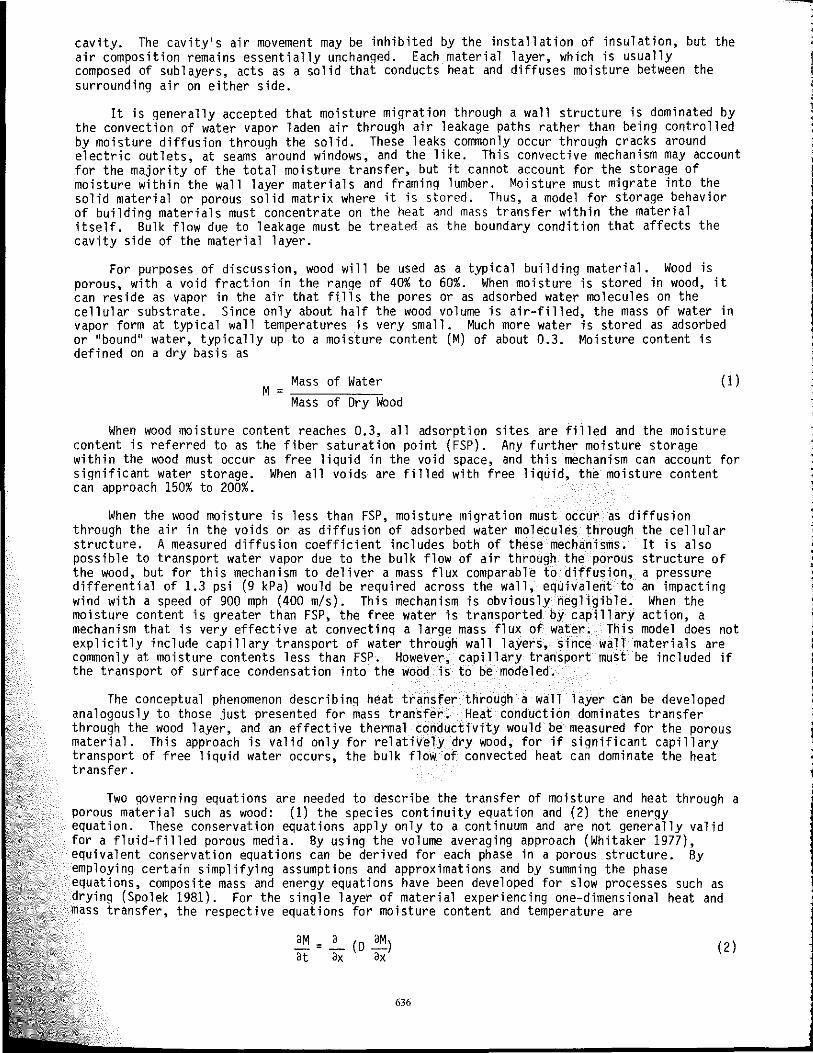
Two governing equations are needed to describe the transfer of moisture and heat through a porous material such as wood: (1) the species continuity equation and (2) the energy equation. These conservation equations apply only to a continuum and are not generally valid for a fluid-filled porous media. By using the volume averaging approach (Whitaker 1977), equivalent conservation equations can be derived for each phase in a porous structure. By employing certain simplifying assumptions and approximations and by summing the phase equations, composite mass and energy equations have been developed for slow processes such as drying (Spolek 1981). For the single layer of material experiencing one-dimensional heat and mass transfer, the respective equations for moisture content and temperature are
aM = a (0 aM) at ax ax
636
(2 )
aT a aT p Cp __ = __ (K --)
at ax ax (3) where 0 and K represent the effective mass diffusivity and thermal conductivity, respectively. By assuming that 0 and K are constant, as a first approximation, the governing equations are reduced to the form
aT
at
where a is the effective thermal diffusivity.
(4)
(5 )
In order to solve the governing equations, the boundary conditions on M and T at the surfaces must be specified. The boundary conditions are shown conceptually in Figure 1, where at each surface the convection from the surrounding air is set equal to the diffusion through the solid material. The heat transfer, when expressed in common terminology, is
h (T - T ) 00 surface K!I
ax surface
(6)
When simultaneous mass flux of a condensible· fluid occurs, the latent heat of condensation/evaporation must be included since it will affect the temperature distribution. Mass transfer through the wood is dominated by diffusion of adsorbed water molecules, and water adsorption causes the release of activation energy (similar to latent heat but of slightly greater magnitude). Since adsorption is a surface phenomenon, diffusive mass flux can be treated as equivalent to surface condensation, so the latent heat release affects the boundary condition only:
h(T - T ) + m h 00 surface fg
where m is the moisture mass flux.
K aT aXsurface
The diffusive mass flux into the wood can be written according to Fick's law as
. m = - p
wd o aM
ax surface
(7)
(8 )
The convective transfer of moisture to the surface can be written in terms of the difference in water vapor partial pressure as
. m = hm (Pwv - Pwv )
00 surface (9)
The partial pressure is used as a measure of the moisture content of the surrounding air because M as defined by Equation 1 has no meaning in air. In order to equate Equations 8 and 9 at the surface, another relationship is needed. If local mass equilibrium is assumed at the surface, the sorption isotherm, which is the relationship between wood moisture content and air relative humidity, can be used. This relationship demonstrates temperature dependence and hysteresis between sorption and desorption curves (Wood Handbook 1974), but both of these effects have been neglected as a first approximation. The resulting curve still exhibits a strong nonlinearity between M and Pwv (determined from relative humidity since surface
637
temperature is calculable). A quasilinearization was performed by using a piecewise linear function so that a linear expression could be developed to express
Pwv = f(Msurface) surface
Thus, the convective mass transfer boundary condition is written in terms of the single dependent variable, M, as
h[P -f(M )]=-P m wv 00 surface wd
D~ ax surface
The convective mass transfer coefficient was derived from the convective heat transfer coefficient using the Lewis analogy and, using the ideal gas law for air, was expressed as
0.622 h 0 2/3 h m 1/3
Pa Cp Ka Ra T a
computer ~imu1ation
(10)
(11 )
(12)
Analytic solutions for the governing Equations 4 and 5 are possible only for a few simple bondary conditions. Therefore, a numerical solution is employed. A finite difference method using backward difference in time and central difference in space is used, resulting in a fully implicit formulation. This approach has been chosen because the solution is inherently stable even when large time steps are taken, an advantage in reducing computation time for slow transfer' processes such as moisture migration in walls.
The governing equations have been decoup1ed for the current solution by simplifying assumptions. When coupling is later included, it can be incorporated by using the measured dependence of the transport coefficients on the dependent variables M and T. In that case, the previously calculated nodal values of M and T can be used to adjust the transport coefficients since their values change slowly. This amounts to a linearization that still retains the decoup1ing of governing equations, so they can be solved separately. The implicit formulation for each equation yields a tridiagonal matrix that is solved using the Crout reduction algorithm.
The computer code reads boundary conditions and other user variables from an external file. The solution produces the values for moisture content and temperature at each node for each time step and stores it in an external file. The file is then loaded into a plotting routine for output.
RESULTS
The theory and equations described are general and can be applied to any composite wall with any specified boundary conditions. The governing equations for the transfer of moisture and heat have been developed to include the important contributions of mass and enthalpy storage. The equations for the convective transfer of mass and heat at the boundaries are written to allow the use of transient as well as constant conditions. The constitutive equation that relates the material moisture content to the vapor pressure in the air has been included in the numerical method that solves the governing equations. At this stage, it is a straightforward matter tO,cascade the equations together to represent a layered wall that is typical of house construct10n today. It is also fairly simple to incorporate variable transport coefficients, such as the dependency of the thermal diffusivity and the mass diffusivity on local moisture conten~ and.tempe~ature. These effects have not been included at this stage, because the basic model 1S st111 be1ng tested for a simple geometry. This paper reports only those results of the model when applied to a fairly simple problem.
As a test case, the model has been applied to a single layer of softwood exposed to freely circulating air on both sides. The wood layer is 1.8 in (45 mm) thick. divided into soatial
638

increments of 0.2 in (5 mm). The assumed constant transport properties are a thermal diffusivity of 1.3E-6 ft2/s (1.2E-7 m2/s) and a moisture diffusion coefficient of 1.1E-9 ft2/s (1.0E-10 m2/s). The variables that are changed for each run of the program are, for both outside and inside conditions, the convective coefficient, the ambient temperature, and the ambient vapor pressure. The actual values used for the three cases discussed in this paper are listed in Table 1. For all cases the initial conditions were set for uniform moisture content of 0.25 and temperature of 77 F (25°C) and the time increment was 10 minutes. As output the program plots either the spatial distribution of moisture content and temperature as it ~aries with time, or the time-varying average values, from which a characteristic time constant can be determined if step function boundary conditions are used.
The first test case simulates the drying of relatively moist green lumber used as wall studs in a cavity. The surrounding conditions are assumed to change abruptly and remain constant as the wood dries. Figure 2 gives the temperature and moisture content distributions through the wood after different durations of drying.
The second test case was formulated to represent the worst case external conditions subjected to a single-layer wood wall, intended to recreate conditions under which condensation would be expected. Hence, the inside air is very humid and warm while the outside air is very humid and cold. For this set of conditions, Figure 3 shows the spatial distribution of temperature and moisture content at different times.
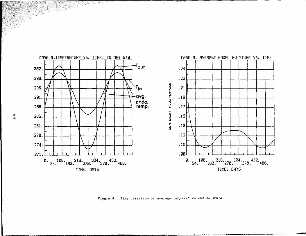
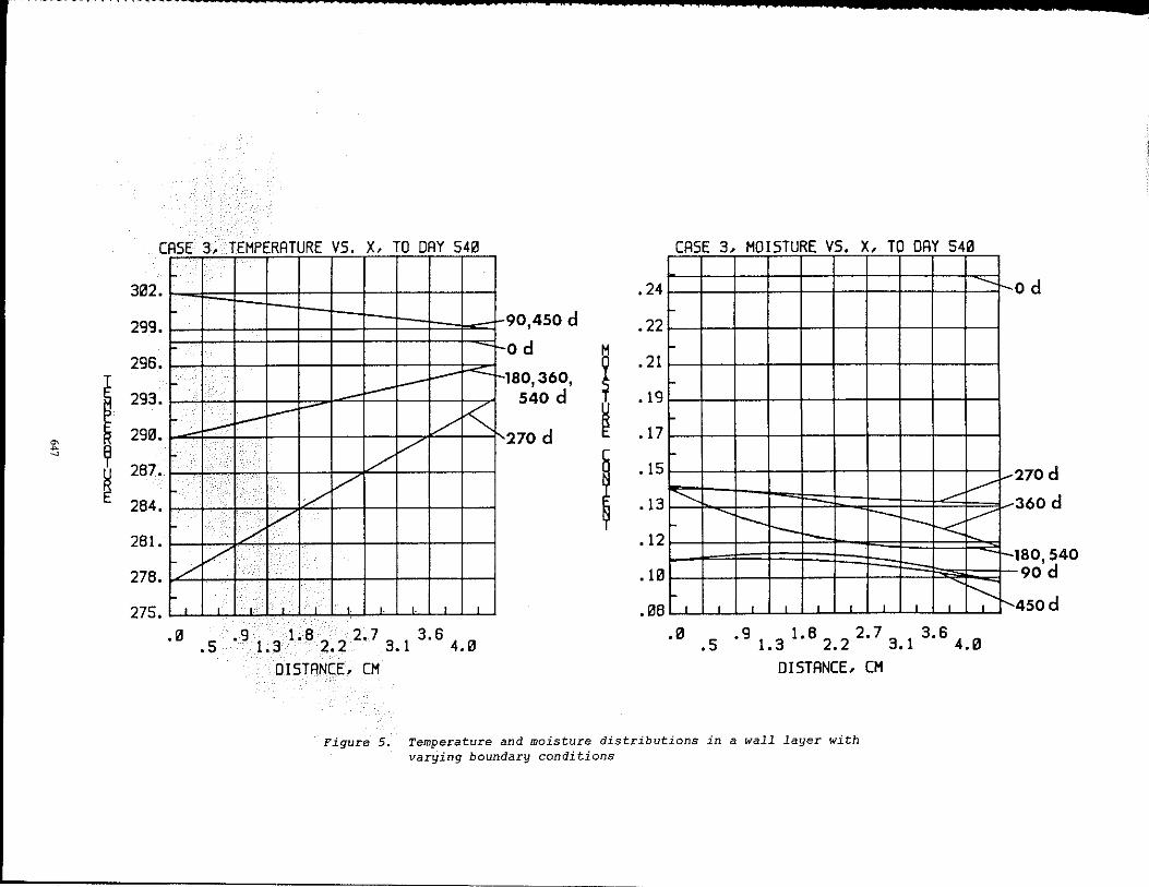
The third test case represents more realistic conditions, although still on a single-layer wood wall. For this simulation, the inside conditions are held at 77 F (25°C) and 50% relative humidity the year round. The outside conditions vary sinusoidally in both temperature and vapor pressure, with a period of 360 days. A plot of the external and internal conditions is given in Figure 4, along with the time variation of the average wall temperature and moisture content. Figure 5 shows the spatial distribution of temperature and moisture content at different times.
DISCUSSION
The numerical solution, being fully impl icit, is inherently stable and demonstrates none of the oscillation that the Crank-Nicolson technique shows when small time increments are used (Kohenen 1984). Even though large time steps do not cause instabil ity, they still can lead to inaccuracy. Since previous time step linearization was employed, fairly small time steps were used to enhance accuracy.
Overall, the predictions of the model are consistent with expectations of diffusive equations. Both the temperature and moisture content profiles tend to smooth out local effects and approach a steady-state distribution for constant boundary conditions. The transient response of the moisture transfer is much slower than that for the heat transfer, so that to a large extent the two phenomena are independent in time. The coupling via the latent heat effect at the surface still exists, but that effect is small.
The discrepancy between the time response of heat and mass transfer is clearly illustrated in Fi gure 2, where constant boundary cond it ions are app 1 i ed to both si des of a s imul ated wall stud. The temperature achieves its steady-state distribution in less than one day while the moisture is still being redistributed after fifty days. The apparently fixed moisture content at ~he surfaces of the wood slab throughout the drying period indicates that the exterior res1stance to mass transfer by convection is negligible compared to the internal diffusive resistance. This result confirms the previous statement that the lumped parameter approach to modeling changes in moisture is not justified.
The average wood moisture content decays exponentially with time, indicative of what is called the falling rate drying regime (the drying rate is proportional to the current moisture content). The characteristic time constant for the drying of framing lumber can be determined to be about 25 days, which is comparable to the value of 90 days assumed by Cunningham (1983b) for.his model calculati?ns. These values are of the same order of magnitude and would probably be 1n closer agreement 1f the current study had used a lower value for the convective coefficient that occurs with the addition of insulation in the wall cavity.
Figure 3 illustrates the temperature and moisture distribution in a single-layer wall
639
exposed to differing boundary conditions on each side. The geometry is physically unrepresentative of an actual wall, but the simulation does demonstrate the temporal changes within the layer. Again, the temperature distribution approaches steady state much faster than the moisture content. The slow redistribution of the moisture indicates the wood's storage effect on the mass transfer. When the boundary conditions change abruptly, the inside surface absorbs moisture while the outside surface releases it. The boundary conditions used for this simulation force the inside surface to a moisture content greater that the FSP, which implies that free water as condensation on the surface must exist. Whether the condensation accumulates or wicks into the wood depends on the magnitude of the capillary transport. The current model does not explicitly include capillary transport, but an order of magnitude approximation using measured capillary properties of wood (Spo1ek and Plumb 1981) indicates that the capillary transport would probably be orders of magnitude great~r than diffusive transport. Thus, the surface condensation would probably be transported into the wood and stored in its void space, and the moisture content at the surface would not exceed the FSP.
The effects of an annual variation of the external temperature and vapor pressure are simulated to give the results shown in Figures 4 and 5. It is clear that both the temperature and moisture distributions vary with the external conditions. The temperature distribution is almost linear for each time shown, indicating that it tracks the ambient condition directly. The curvature in the moisture distributions for the same times demonstrates its slower response and the capacity to store moisture. Figure 4 indicates that relatively high moisture content and temperature can occur simultaneously because of the lag in summer drying of moisture (see the curves for time = 350 days). However, the conditions are not severe and probably do not persist not long enough to induce dry rot.
Future Work
Now that the model has been developed and determined to produce reasonable results for a simple case, it will be refined to more acurate1y represent an actual wall. There are three modifications that are anticipated to demonstrate a large effect on the calculated moisture and temperature distributions:
1. Layered wall: Since walls are typically constructed of several layers, the conservation equations will be applied to each different material. Interfacial boundary conditions will be used.
2. Variable transport coefficients: The local temperature and moisture content of a material will affect the value of its transport coefficients. Wood, for example, demonstrates a strong dependence of its diffusion coefficient on both temperature and moisture content. These effects will be included by using the currently calculated values of M and T to update the transport coefficients.
3. Capillary transport: Capillary transport of free liquid can dominate the mass transfer. Its effect will be included as a moisture content gradient driven phenomenon (like diffusion) by relating the capillary pressure to the local moisture content.
CONCLUSION
A fully transient model of heat and mass transfer in wall layers has been developed. The governing equations were solved using an implicit finite difference method. As a test case, a single wood layer exposed to differing boundary conditions was modeled. The results of those calculations indicate the following:
1. The characteristic times for transfer of heat and moisture are distinctly different, with heat transfer occuring approximately two orders of magnitude faster than mass transfer.
2. The storage of water in a wood layer can be significant and, because of the slow mass transfer, may allow high moisture content to occur in wood after seasonal warming begins. .
640
3. While severe boundary conditions can induce surface condensation, capillary transport of that liquid into the wood's porous structure is probably sufficient to prevent an observable accumulation of moisture.
NOMENCLATURE
Cp : specific heat of air, J/Kg'K
o : effective mass diffusivity, m2/s
FSP fiber saturation point
h : convection coefficient (thermal), W/m2'K
hm : effective mass convection coefficient, s/m
hfg : enthalpy of phase change (fl ui d to vapor), J/Kg
K : thermal conductivity, W/m'K
m moisture mass flux, Kg/m2·s
M : moisture content, mass of water/mass of dry wood
P : pressure, Pa
R : gas constant, J/Kg K
T : temperature, Kelvin
t : time, s
X : spatial variable, m
Greek Symbols
~ : effective therma, diffusivity, m2/s
p : density, kg/m3
Subscripts
~ : ambient conditions
surf: surface conditions
wd : wood
wv : water vapor
a : air
REFERENCES
ASHRAE. 1981. "Vapor migration by diffusion." ASHRAE Handbook - Fundamentals, ASHRAE Inc., pp. 21.3 - 21.9.
641

Cunningham, M.J. 1983a. "A new analytical approach to the long term behavior of moisture concentration in building cavities - I. Non-condensing cavity." Building and Environment, V. 18(3), pp. 109 - 116.
Cunningham, M.J. 1983b. "A new analytical approach to the long term behavior of moisture concentration in building cavities - II. Condensing cavity." Building and Environment, V. 18(3), pp. 117 - 124.
Incropera, F.B., and DeWitt, D.P. 1985. Fundamentals of heat and mass transfer. John Wiley & Sons, p. 282.
Johnson, R.J. 1982. "Residential moisture conditions - Facts and experience." ASTM STP 770, pp. 234 - 240.
Kohenen, R. 1984. "Transient analysis of the thermal and moisture physical behavior of building constructions." Building and Environment, V. 19(1), pp. 1 - 11.
Plumb, O.A.; Spolek, G.A.; and Olmstead, B.A. 1985. "Heat and mass transfer in wood during drying." International Journal of Heat and Mass Transfer, V. 28(9), pp. 1669-1678.
Sherwood, G.E., and Peters, C.C. 1977 "Moisture conditions in walls and ceilings of simulated older home duri nq wi nter." U. S. Forest Products Research Laboratory Research Paper FPL -290.
Sherwood, G.E. 1983. "Condensation potential in high thermal performance walls - Cold winter cl imate." U. S. Forest Products Research Laboratory Research Paper FPL 433.
Spolek, G.A. 1981. "A model of simultaneous convective, diffusive, and capillary heat and mass transfer in drying wood." Ph.D. thesis, Washington State University.
Spolek, G.A., and Plumb, O.A. 1981. "Capillary pressure in softwoods." Wood Science and Technology, V. 15, pp. 189-199.
Stewart, M.B. 1981. "Anual cycle moisture analysis." Proceedings of the ASHRAE/DOE - ORNL Conferenec, Thermal Performance of the Exterior of Buildings, pp. 887 - 896. Atlanta: American Society of Heating, Refrigerating and Air-Conditioning Engineers.
Stewart, M.B. 1982. "An experimental approach to the study of moisture dynamics in walls." ASTM STP 779, pp. 92-101.
Tenwolde, A. 1983. "The Keiper and MOISTWALL moisture analysis method for walls." Proceedings of the ASHRAE/DOE Conference, Thermal Performance of the Exterior of Buildings ll, pp. 1033 - 1050. Atlanta: American Society of Heating, Refrigerating and Air-Conditioning Engineers.
Tsongas, G.A. 1980. "A field study of moisture damage in walls insulated without a vapor barrier." Oak Ridge National Laboratory Report ORNL/Sub-78/97726/1.
Tsongas, G.A. 1983. "The Spokane wall insulation project: A field study of moisture damage in walls insulated without a vapor barrier." Bonneville Power Administration, Portland, OR.
Turner, W.O.; Elrod, D.C.; and Simon-Tov, I. I. 1976. "HEATING5--An IBM 360 heat conduction program." Oak Ridge National Laboratory Report ORNL-CSD-TM-15.
Wang, F .S. 1979. "Comparative studies of vapor condensation potentials in wood framed Proceedings of the ASHRAE/DOE - ORNL Conference, Thermal Performance of the Exterior
1;B-:-:u Tilf:dnir:n:-:q""s "-, ":p::p:-:.-;;8~36f--'-_"'i\8ii4:';'7 "'. '""'A"'t'l-=-a n='t"'a,,:"'--'iiAm='eO'r'"'iC'::c-=a"n "*So c i e t y of He a tin g , Ref rig era t i ng and Air-Conaitioning Engineers.
walls. " of
Weidt, J.L. 1978. "Minnesota retrofit insulation in situ test program." Minnesota Energy Agency Report HCP/W2843-01.
Whitaker, S. 1977. "Simultaneous heat, mass, and momentum transfer in porous media: A theory of drying." Advances in Heat Transfer, V. 13, pp. 119-203.
642

Wilkes, K.E. 1983. "Dynamic thermal performance of walls and ceilings/attics." Proceedings of the ASHRAE/DOE Conference, Thermal Performance of the Exterior of Buildin~s II, pp. 131 _ 159. Atlanta: American Society of Heating, Refrigerating and Air-Conditlonlng Engineers.
Wood Handbook. 1974. U.S. Forest Products Researcy Laboratory.
Zarling, J.P.; Rice, E.; and Swanson, K.C. 1982. "Moisture problems in buildings in the subarctic." ASTM STP 779, pp. 262 - 274.
TABLE 1 Boundary Conditions for Test Cases
Case 1 2 3
Physical Drying of wall Single layer wall Single layer wall Description studs in leaky with extreme mois- with constant in-
cavity, same cond- ture conditions inside conditions itions on both both inside and and sinusoidal sides. outs ide. outside conditions.
Outside Convective Coef.
0.88 (5) 1. 76 (IO) 1.76 (IO)
Btu/hr-ft2-F (W/m2-K)
Temperature F (K) 54 (285) o (273) (288 + 15 sin wt) Vapor 0.17 (1170) 0.09 (611) (1367 + 756 sin wt) Pressure psi (Pal
Relative 60 100 variable Humidity (%)
Inside Convective 0.88 (5) 1. 76(10) 1.76 (10) Coef. Btu/hr- ft2_F (W/m2-K)
77 (298) 77 (298) Temperature F (K) 54 (285) Vapor 0.17 (1170) 0.36 (2456) 0.23 (1585) Pressure psi {Pal
Relative 60 78 50 Humidity (%)
.
643

t:
HEAT TRANSFER
h (1nf -~r~ +mhf ,
MASS TRANSFER
h m (Pwv -Pwv ) inf srf
-
'-K (oT / OX)
pw~ 0 (a ~ / (} x)
Figure 1. Boundary conditions
CASE 1, TEMPERATURE VS. X, DAY 1 • 0-' ,_ _ •
302
299 oh
296 I 293
290 r-- -- - -< lh
~ 287.
284.
e-. 6h 2-24h
I i
281.
278.
275. , .0.5.91.31.82.22.73.13.64.0
DISTANCE, CN
.29
.27
.26
.24
.23
.21
• 20
.18
• 17
.15
CASE 1, MOISTURE VS. X, TO DAY 50
----
- V V /' "--.. '" '\ - I /, / "" ,\ y
. V /' I"'" .'\ ~~ Ip - ~I--.
.0 .90
1.822
2.70
3.6 .5 1.0 . 0.1 4.0
DISTANCE, CN
od
I d
5d lod 20d 50 d
Figure 2. Temperature and moisture distribution in a wall stud
• •• t. _. ~---' ......... ~_~ __ .. _ ... _ .. ,~_. .. ~ ~ _. ____ .. _~ __ j

302.
299.
296.
293.
290.
~ 287.
'" .. ~
284.
281.
278.
275.
CASE 2, TEMPERATURE VS. X, DAY 1
r V ---/ ...c:::.
..- ./' V ./'
V
-oh 1 h
6-24h
.37
.34
~ .30
.27
~ .24
CASE 2 , MOISTURE VS. X, TO DAY 50
r
r I~ ~ ~/
L ~ K: DL--t-,? V/ K ............
/' ~ ~ V "- "'-"-r '" / V I .21 ;, ~ ';/ " /'" ,/
:/ V /'"
.18
.14 .p I'
""/ V .11
, , , I I , , , .08 r, , I I • •
.05.9131.8222.733.6 • • . . 1 4. B .0 .5 .91.31.8 2. 2 2.7 3. 1 3.6 4.0
DISTANCE, CM DISTANCE, CM
Figure 3. Temperature and moisture distributions in a wall layer with constant boundary conditions
i"
,
50 d
20d
10 d
5d
1d
od
~ A ~
CASE 3,TEMPERATURE VS. TIME, TO DAY 540
/"" ~
r /" ~ f ~ 302.
298.
r1 \ 1 \" f-, l\ L ,\
/ \
~ \\ /1 \
r- \ 1"-'/ / r- \ /
295.
291.
288.
285.
281. r
r \ / r- \.. V
278.
274.
271. , , , , , , , , , ,
0. 54,1138'162,216'270,324'378.432'486.
TIME- DAYS
i'
·Tout
y. In
avg. nodal temp. I
I
CASE 3, AVERAGE NODAL MOISTURE VS. TIME
.24
.22
.21
.19
.17
.15
.13
.12
. Ii'
.138
~\
r- \ r
""" I"" \ V ~ ..... f-/ --, , , ,. ,. • , . , , 13. 54.1138'162.216'2713.324'378.432'486,
TIME, DAYS
/ ,
Figure 4. Time variation of average temperature and moisture
I
.-------~
I '" ... ~ ~
~
CASE 3, TEMPERATURE VS. X, TO DAY 540 CASE 3, MOISTURE VS. X, TO DAY 54a . --
3a2.
299.
29S.
293.
29a.
287.
284.
281.
278.
275.
.24 ---r- -90,450 d .22
-f- ----r- --
~ - <---~ V /"
/'
r- /' /"
./' /'
od
I .21
180,360, 540 d .19
270 d .17
I .15
.13
.12
-
V ............ ------
----- ------k V r-------/"
/' .la r- I'---, , ,. , ,. ,. , , .a8 , , , , , , , , , ,
.a 5.91 1.8 22 2.7 3 3.6 •• 3 •• 1 4.0 .a .5 .9 1.3 1.8 2•2 2.7 3.1 3.S 4.a
DISTANCE, CM DISTANCE, CM
Figure 5. Temperature and moisture distributions in a wall layer with varying boundary conditions
od
f.--: 270d
360 d
r-l 180,540 90 d
450d 1'-,


![Transient Mass-Loss Events in the PG 1159 [ WCE ] Central Star of Longmore 4](https://static.fdocuments.us/doc/165x107/5681593f550346895dc67e7f/transient-mass-loss-events-in-the-pg-1159-wce-central-star-of-longmore.jpg)