TRANSIENT BACKSCATTER CHANNEL...
6
TRANSIENT BACKSCATTER CHANNEL MEASUREMENTS AT 5.8 GHZ ACROSS HIGH-VOLTAGE INSULATION GAPS Christopher R. Valenta, Patrick A. Graf, Matthew S. Trotter, Gregory A. Koo, and Gregory D. Durgin, Ph.D. School of Electrical and Computer Engineering, Georgia Institute of Technology 777 Atlantic Dr., Atlanta, Georgia 30332-0250 William G. Daly, P.E. Gwinett County Georgia School System 50 Taylor Road, Suwanee, Georgia 30024 Bradley J. Schafer Southern States, LLC. 30 Georgia Avenue, Hampton, Georgia 30228 ABSTRACT This study demonstrates the operation of 5.8 GHz backscatter radio links in a transient, high-voltage commercial power line environment. The measured results demonstrate that increased RF carrier frequency provides additional resistance to the noise, interference, and corona shielding of communication antennas that operate on high-voltage lines. This study also lists rules to assist in the design and implementation of low-powered wireless sensor applications for the future smart grid. Keywords: Electromagnetic Testing, Measurement, Microwave, Noise, RFID, Scattering 1.0 Introduction It has been known for years that high-voltage transmission systems produce above average levels of radio interference, providing an extra challenge for radio frequency (RF) system designers [1]. These links must be resilient in the harsh, charged-particle and impulsive- noise power systems environment in order to provide efficient communication. For instance, Wang et al. [2] have measured the performance of an 802.11b link in a high-voltage environment and determined that the link’s data rate is reduced 80% by the electromagnetic interference generated by the breakdown of sulfur hexafluoride (SF6) gas, a common dielectric for high- voltage applications. Due to this unreliability and the short lifetimes associated with sensor power supplies, these types of systems have been largely avoided by the power industry. The benefits of using radio links in high-voltage environments are pivotal to the successful implementation of a “smart power grid” [3] [4]. The principle motivating application for the links study in this paper is remote fault detection at power substations. For example, capacitor banks at wind farms such as in Fig. 1 are dynamically switched in order to balance the ever-changing power factor – a scenario that requires careful equipment monitoring and sensing. Outfitting these substations with a 5.8 GHz backscatter radio sensor system would provide the information necessary to efficiently and effectively manage the power factor. Remote fault detection is also pivotal in avoiding catastrophic substation failures. These failures, possibly resulting in fires and explosions, can be caused by sudden equipment malfunctions, switching transients, and lightning strikes [5]. Wired monitoring solutions are Fig. 1. Image of high-voltage switches for capacitor banks at a wind farm in Illinois. Due to the constantly changing power factor that results from the use of wind turbines, capacitors must be switched into and out of the grid to cancel the effects of reactive power on the lines.
Transcript of TRANSIENT BACKSCATTER CHANNEL...
TRANSIENT BACKSCATTER CHANNEL MEASUREMENTS AT 5.8 GHZ ACROSS HIGH-VOLTAGE INSULATION GAPS
Christopher R. Valenta, Patrick A. Graf, Matthew S. Trotter, Gregory A. Koo, and
Gregory D. Durgin, Ph.D. School of Electrical and Computer Engineering, Georgia Institute of Technology
777 Atlantic Dr., Atlanta, Georgia 30332-0250
William G. Daly, P.E. Gwinett County Georgia School System
50 Taylor Road, Suwanee, Georgia 30024
Bradley J. Schafer Southern States, LLC.
30 Georgia Avenue, Hampton, Georgia 30228
ABSTRACT
This study demonstrates the operation of 5.8 GHz backscatter radio links in a transient, high-voltage commercial power line environment. The measured results demonstrate that increased RF carrier frequency provides additional resistance to the noise, interference, and corona shielding of communication antennas that operate on high-voltage lines. This study also lists rules to assist in the design and implementation of low-powered wireless sensor applications for the future smart grid. Keywords: Electromagnetic Testing, Measurement, Microwave, Noise, RFID, Scattering
1.0 Introduction
It has been known for years that high-voltage transmission systems produce above average levels of radio interference, providing an extra challenge for radio frequency (RF) system designers [1]. These links must be resilient in the harsh, charged-particle and impulsive-noise power systems environment in order to provide efficient communication. For instance, Wang et al. [2] have measured the performance of an 802.11b link in a high-voltage environment and determined that the link’s data rate is reduced 80% by the electromagnetic interference generated by the breakdown of sulfur hexafluoride (SF6) gas, a common dielectric for high-voltage applications. Due to this unreliability and the short lifetimes associated with sensor power supplies, these types of systems have been largely avoided by the power industry.
The benefits of using radio links in high-voltage environments are pivotal to the successful implementation
of a “smart power grid” [3] [4]. The principle motivating application for the links study in this paper is remote fault detection at power substations.
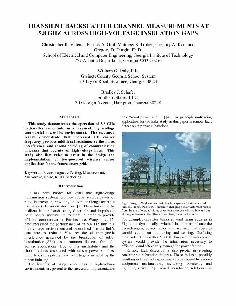
For example, capacitor banks at wind farms such as in Fig. 1 are dynamically switched in order to balance the ever-changing power factor – a scenario that requires careful equipment monitoring and sensing. Outfitting these substations with a 5.8 GHz backscatter radio sensor system would provide the information necessary to efficiently and effectively manage the power factor.
Remote fault detection is also pivotal in avoiding catastrophic substation failures. These failures, possibly resulting in fires and explosions, can be caused by sudden equipment malfunctions, switching transients, and lightning strikes [5]. Wired monitoring solutions are
Fig. 1. Image of high-voltage switches for capacitor banks at a wind farm in Illinois. Due to the constantly changing power factor that results from the use of wind turbines, capacitors must be switched into and out of the grid to cancel the effects of reactive power on the lines.

difficult and unsafe across the high-voltage insulation gap due to dielectric breakdown; current transformer (CT) tanks that perform a wired measurement of high voltage lines inside an insulating oil tank are expensive and themselves present a failure point and fire hazard. 5.8 GHz backscatter is well-suited for this high-voltage environment because it is extremely low power (instant turn-on, which is required for fault detection), high-frequency (resistant to corona shielding), and secure (short-range, difficult to jam/spoof/intercept).
Reliable radio links along with low-power sensors would allow real-time monitoring of a variety of power line conditions, including fault detection, temperature, and line sag. Sensors utilizing backscatter radio, particularly at 5.8 GHz, allow many of the aforementioned problems to be avoided [6].
This paper first presents background on the radio interference of high-voltage environments and SF6 gas in particular. The radio interference of time-dependent flashovers on a 5.8 GHz backscatter link is then measured in the following section. Next, a RF interference measurement of a faulty switched placed in an SF6 container are shown. Finally, a list of design rules for backscatter sensors or RF devices operating in high-voltage environments is presented.
2.0 Description of High-Voltage Environment
The high-voltage environment exhibits several key behaviors that affect physical layer RF channels, many of which differ from conventional wireless systems. These attributes include thermal noise, impulsive noise, and plasma shielding. These attributes result from the characteristics of the strong electric fields that build up around high-voltage power lines. Corona generation and arc flashovers, both impulsive and steady-state, can be present in this type of environment.
2.1 Radio Interference Sources
Arc flashovers result from short circuits that are characterized by large amounts of current, bright sparks, and loud noises. Large electric fields between conductors will cause dielectric breakdown resulting in an arc. While natural lightning discharges on the order of 100µs and up to 400kA, man-made sources may exist for shorter or indefinite time periods which may affect RF communication [5]. It has been shown by Skomal, Betz, et al. [7] [8] that lightning and man-made sparks produce electromagnetic signals rich in spectral content. However, the most important figure in determining the contribution of this contact to radio interference is the arc’s transition time. The shorter the time, the wider range of frequency content that will be generated [9].
2.2 Radio Channel Effects
Corona and arc flashover events add both broadband and impulsive noise that result from the time-dependent
transition times of the negative corona Trichel Pulses and the flashover discharge time [9]. While the majority of spectral energy for these pulses exists at frequencies less than 200 kHz, there are significant contributions through the VHF radio bands (less than 300 MHz) as measured by [10]. As expected and measured by Sporn and Monteith [1], radio channel interference is directly proportional to line voltage. Moreover, the energy at high frequencies is inversely proportional to the transition time. Therefore, a 5.8 GHz system should experience minimal effects from noise sources with microsecond-scale time variations.
2.3 Use of SF6 Gas
The first industrial use of SF6 gas for power switching was performed by Westinghouse in the early 1950’s [11]. SF6 gas was identified as having excellent thermal and dielectric properties that helped to overcome the technical challenges of extinguishing high-voltage arcs. The high dielectric strength allows smaller gaps between high-voltage components reducing the overall size and weight of devices. The thermal properties of SF6 allow the gas to better quench arcs during switching operations. While the choice of this gas helps to improve equipment performance, these qualities also cause shorter arc transition times (on the order of nanoseconds) that produce higher frequency electromagnetic emissions. Therefore, devices that use this dielectric may potentially generate more harmful, high frequency radio interference than devices that use air gaps.
3.0 Microwave 5.8 GHz Testbed and RF Tag
The 5.8 GHz testbed consisted of a transceiver in a bi-static antenna arrangement, a signal generator, and PC used for sampling and data processing as shown in Fig. 2 [12]. The direct-conversion receiver operates in the range
Fig. 2. Block diagram of the 5.8 GHz communication system in bi-static antenna configuration. BBI and BBQ represent the base-band in-phase (BBI) and quadrature (BBQ) signals, respectively. BB1 and BB2 connect two internal boards in the receiver.

of 5725-5850 MHz in the ISM band. It then converts the in-phase and quadrature elements of the received signal to DC where it is sampled by an analog-to-digital converter and processed [13]. A signal generator is used to produce the 5.79 GHz carrier wave for the transmitted signal and also provides a frequency reference for the receiver down conversion.
The RF tag in Fig. 3 repeated a 500 kHz pseudo-random (PN) sequence with a length of 31 bits. This spread spectrum sequence allowed the communication system to spread its frequency content along a range of frequencies making it less prone to interference and narrowband jamming. To reclaim the tag’s data, the receiver performs a cross-correlation of the down-converted received signal with an identical, locally generated PN sequence. This cross-correlated data was then normalized with the auto-correlated, locally generated PN sequence. The normalized data was then time-averaged 16 times to produce a reliable complex channel coefficient that measures signal levels on the in-phase and quadrature backscatter components. This measurement technique is discussed exhaustively by Griffin in [12].
The PN sequence was generated on the RF tag by using
a Microchip PIC microcontroller (PIC18F2520). The 31-bit sequence can be generated by using a 5-bit shift register. The outputs of the 2nd and 5th registers were XOR-ed together and fed into the input of the 1st register in order to generate this sequence. As shown in Fig. 4, this microcontroller was connected to a microwave gallium arsenide, pseudo-morphic, high electron mobility transistor (PHEMT) switch (M/A-Com MASW-007207 V2). This switch allowed the RF tag to change the 5.79 GHz patch antenna’s load between an open and short-circuited state. These opposite impedances allowed the tag to modulate the incoming signal.
4.0 Transient Noise Measurements
4.1 Experimental Design
The purpose of the transient – flashover ‘Lightning’ test is to determine whether a 5.8GHz backscatter radio communication is possible in the presence of transient - flashover arcs. A Marx generator was used to generate a high-voltage that would flashover between two conducting rods. The Marx generator accomplishes this task by charging several stages of capacitors from a common, constant voltage source. The maximum output voltage of the device will then be approximately equal to the product of the number of stages and the voltage charged per stage. When all capacitors are charged, a controllable spark gap creates a new low-impedance path for the circuit in which all capacitors can discharge [14].
In our case, the low impedance path included an air gap between two metal rods as seen in Fig. 5. Thus, when the circuit discharged, an arc would be created between the two metal rods. The Marx generator used 11 stages whose capacitor values were nominally 0.6µF and rated at 75 kV. These capacitors were charged until the output
Fig. 5. Diagram of spark gap setup relative to transmit and receive antennas. All devices were placed on a large metal ground plane that was attached to the quasi-shielded room’s ground.
Fig. 4. Circuit diagram of the 5.8 GHz RF tag, modified from [13].
Fig. 3. Image of 5.8 GHz RF tag. The RF tag is printed on a 2 layer FR-4 PCB and contains a 5.8 GHz slot antenna, switching transistor to change the antenna’s impedance between and open- and short-circuit antenna loads, and a microcontroller to produce the PN sequence.

voltage was approximately 310 kV line-to-ground. The transmit and receive antennas were connected to a
digital oscilloscope whose trigger was attached to the Marx generator. Therefore, only the instance of the arc discharging would be recorded.
4.2 Measured Results
Before testing tag functionality, it was of interest to see how the lightning waveform appeared on the vertically polarized receiving patch antenna, which has localized frequency reception at 5.79 GHz compared to a 3 meter long, horizontally polarized wire antenna. Broadband radiation from sparking is sufficiently depolarized, so the antenna orientation should make little difference. The time domain plot of the received waveforms as measured at the antenna terminals with an oscilloscope for the patch and wire antennas can be seen in Fig. 6 and Fig. 7, respectively.
The patch antenna waveform has peak power 28.5 dB
less than the wire antenna at 5.8 GHz. Thus, this narrowband patch antenna more effectively filters the noise power of a lightning strike, whose spectral content is greater at low frequencies. Therefore, the radio design, which is built to operate at 5.8 GHz, strongly mitigates the effects of lightning, which might otherwise be seen at lower frequencies. Also, the noise has duration of less than 1 microsecond, meaning that the effect on data transmission and bit loss would be minimal (providing chip time was sufficiently low).
Finally, after analyzing the system without an active tag signal, the RF tag was activated and the effects of a lightning strike on the tag were witnessed. As can be seen in Fig. 8, the strike caused the tag to reset, and it stopped broadcasting its PN sequence for approximately 65 milliseconds. However, it is important to note that the tag reactivated itself and continued broadcasting after the
interference signal dissipated. This outcome is similar to the effects on WiFi radios seen in [2]. This reaction shows
that, due to the early stage of prototype development and lack of proper shielding, the lightning was able to reset the microprocessor on the RF tag. However, the tag was undamaged and continued to function and transmit its PN sequence.
Since the lack of shielding caused the tag to reset,
rudimentary shielding was constructed using aluminum foil, and the test was run once again. This time the tag functioned throughout the strike, although the transient noise was still visibly present.
For the lightning test, another interesting parameter to address is the RMS delay spread of the environment. The
Fig. 7. Time domain transient of the spark as seen by the horizontally polarized wire antenna. Note how the voltage levels are significantly higher than those received by the 5.79 GHz patch antenna.
Fig. 8. Transient view of the received un-shielded tag waveform as seen by the vertically polarized 5.79 GHz patch antenna. The flashover occurs at time zero and causes the tag to reset (low magnitude voltage), remaining off until 65 ms later when the PN sequence resumes (high magnitude voltage).
Fig. 6. Time domain transient of the spark as seen by the vertically polarized 5.79 GHz patch antenna.

RMS delay spread describes the time-domain dispersion due to reflections in the environment [15]. In short, this parameter can be used to determine the maximum interference time a lightning strike could have on the data signal. For this calculation, two different sets of measured data were used: data from a lightning strike as measured at the output of the receiving patch antenna and data from a lightning strike as measured at the output of the 5.8 GHz receiver. The delay spreads calculated from these two sets of data and were 1.17 µs (as seen by at the antenna output) and 3.83 µs (as seen by the receiver output). The receiver output has a slightly higher delay spread than the antenna because it performs low-pass filtering, which provides smoothing and stretches out the delay. However, both delay spreads are extremely short and would cause minimal data distortions if the digital symbol periods of backscatter signaling was kept greater than or equal to these delay spreads. Also, it should be noted that these delay spreads are a worst-case representation because the test facility was essentially a Faraday cage and reflections were thus higher than in an outdoor line of sight (LOS) environment. Thus, it is not expected that impulsive noise would significantly hamper data transmission.
5.0 SF6 Measurements
5.1 5.8 GHz Testbed Measurements
To determine the effects of an SF6 arc on the 5.8 GHz communication link, the same setup was used as for the transient noise measurements. However, instead of an air gap between two conductors, a pressurized cylinder of SF6 gas containing a high-voltage switch was used. The time-domain response of the system under these conditions can be seen in Fig. 9. As can be observed, the
voltage spike is more narrow in the time domain compared to the discharge through air measurements. This impulsive signal will contribute additional broadband content in the frequency domain as illustrated by the spectral measurements of the failed switch.
5.2 Spectrum Measurements of Faulty Switch
To assist in the determination of the effects of SF6 on communication channels, spectrum measurements were performed on a pressurized cylinder of SF6 gas containing a high-voltage switch. This switch was known to disrupt cell phone communications near the substation containing the switch due to an internal fault. This fault was causing internal, impulsive sparking 120 times per second, during the sinusoidal peaks of every AC cycle. To affect cell phone communications, the switch would have to produce significant spectral content in the UHF bands or have radiated electromagnetic interference that could affect the base station hardware. Therefore, it was of interest to determine the power spectrum of these contributions.
The switch was connected to a high-voltage test production set at 70 kV line-to-ground (119 kV line-to-line) at 60 Hz. A spectrum analyzer using a broadband, bi-conical antenna (500 MHz to 3 GHz) then measured the resulting spectral content from a distance of 10 meters away. The gas pressure in the switch was 355.7 kPa. Spectral measurements were made with the switch connected and disconnected to the power supply in order to verify that the spectral content seen was that from the switch and not from background noise. These measurements were taken by using a maximum hold function on the spectrum analyzer for 20 seconds.
Measurements were taken over several different bands
(5 MHz – 50 MHz, 50 MHz – 250 MHz, 850 MHz – 900 MHz, and 1 GHz – 3 GHz). In the 850 MHz – 900 MHz and 1 GHz – 3 GHz bands, no additional frequency content was measured other than expected GSM and WiFi
Fig. 10. Spectral content of faulty switch in the 5 MHz – 50 MHz band.
Fig. 9. Time domain transient of the received shielded tag waveform (discharge through SF6) as seen by the 5.79 GHz patch antenna. The PN sequence is also interrupted in this case due to the lack of adequate shielding on the RF tag.

signals when the switch was closed. However, content was found in the 5 MHz – 50 MHz and 50 MHz – 250 MHz bands as shown in Fig. 10 and Fig. 11. The spectral
content at these frequencies is consistent with transition times on the order of 4 ns – 200 ns. These results follow the claim that SF6 gas quench arcs on the order of nanoseconds.
6.0 Conclusion
The 5.8 GHz backscatter system worked well in the high-voltage power environment, revealing several interesting design parameters for radio systems in this area. While the system was not impervious to all corona and impulsive-noise conditions, it has been shown that through rudimentary hardware modifications and communication layer protocol implementations, these problems may be overcome.
The following design rules for microwave backscatter and RF devices in general are suggested, especially when operating in high-voltage environments [16]. 1. Keep digital symbols larger than 1 microsecond and
add forward error correction or error detection to maintain reliability in arcs. This will prevent lightning and other arc-over events from making burst errors in the communication link.
2. Add low-pass filters with break points around 250 MHz to receiver antennas to filter out the bulk of air-gap arc over, SF6 spark noise, and broadband corona noise.
3. Small, resonant antenna types with less than 3% bandwidth (like the patch) are preferred for use as transmit, receiver, or backscatter antennas since they provide an extra level of filtering for the broadband noise sources of the high-voltage environment.
4. Extra shielding is needed around all sensor and transceiver electronics – baseband circuits as well as RF devices – to keep impulsive noise from resetting logic circuits and corrupting signal lines.
5. Higher carrier frequencies for in-line sensors should be used as the line voltage increases, as higher UHF and microwave frequencies more effectively penetrate corona plasmas.
6. Avoid sharp points and corners in the design of antennas and physical layout to diminish the build-up of additional corona.
7.0 Acknowledgement
The authors would like to thank Rusty Ortkiese of Southern States, LLC. for his assistance with the measurements and his insight into high-voltage environments.
8.0 References [1] P. Sporn and A. C. Monteith, “Progress Report on Tidd 500-kV
Test Project of the American Gas and Electric Company – Corona, Radio Influence, and Other Factors,” AIEE Summer and Pacific General Meeting, Vol. 69, pp. 891-899, June 1950.
[2] X. Wang et al. “Reliability Test of Using 802.11b Technology In Switchgear for Measurement and Control,” International Conference on Power System Technology, October 2006.
[3] M. Amin, “Toward Self-Healing Energy Infrastructure Systems,” IEEE Computer Applications in Power, pp. 20-28, Vol. 14, No. 1, January 2001.
[4] M. Amin, “Security Challenges for the Electricity Infrastructure,” IEEE Computer Magazine, Special Issue on Security and Privacy, April 2002.
[5] R. B. Carpenter, Jr. and R. L. Auer, “Lightning and Surge Protection of Substations,” IEEE Transactions on Industry Applications, pp. 162-170, Vol. 31, No. 1 January 1995.
[6] G. D. Durgin. “The Hidden Benefits of Backscatter Radio at 5.8 GHz,” URSI 2008, Boulder, CO, January 2008.
[7] E. N. Skomal, “Comparative Radio Noise Levels of Transmission Lines, Automotive Traffic, and RF Stabilized Arc Welders,” IEEE Transactions on Electromagnetic Compatibility, pp. 73-77, Vol. 9 No. 2, September 1967.
[8] H. D. Betz, U. Schumann, and P. Laroche, Eds. Lightning:Principles, Instruments, and Applications: Review of Modern Lightning Research, New York: Springer, 2009.
[9] A. Mazel, High-voltage Engineering: Theory and Practice, Edition 2. New York, NY: Marcel Dekker, 2000, pp. 149-160.
[10] Y. Qingyun, Z. Xijun, S. Guozhi, and Y. Jie, “Research on Frequency Characteristics of Signal Radiated from Corona Discharge,” ICEMI, pp. 3-913 – 3-916. August 2007.
[11] K. Nakanishi, Ed. Switching Phenomena in High-Voltage Circuit Breakers. New York, NY: Marcel Dekker, Inc. 1991, pp. 116.
[12] J. D. Griffin, “High-Frequency Modulated-Backscatter Communication Using Multiple Antennas,” Ph.D. Thesis, Georgia Institute of Technology, Atlanta, Georgia USA, May 2009.
[13] J. D. Griffin and G. D. Durgin, “Multipath Fading Measurements for Multi-Antenna Backscatter RFID at 5.8 GHz,” IEEE International Conference on RFID, pp. 322-329, April 2009.
[14] E. M. Bazelyan and Y. P. Raizer, Spark Discharge, Boca Raton, FL: CRC Press, 1998, pp. 94-96.
[15] G. D. Durgin, Space-Time Wireless Channels. Upper Saddle River, New Jersey: Prentice Hall PTR, 2003, pp. 59-60.
[16] C. R. Valenta et. al., “5.8 GHz Backscatter Sensor Measurement Across High Voltage Insulation Gaps,” The Propagation Group, Georgia Institute of Technology, Atlanta, Georgia USA, Tech. Rep. PG-TR-092004-CRV, April 2009.
Fig. 11. Faulty switch spectral content in the 50 MHz – 250 MHz band.