Transformer protection RET650 Application Manual · PDF file · 2015-05-19Setting...
330
Relion ® 650 series Transformer protection RET650 Application Manual
Transcript of Transformer protection RET650 Application Manual · PDF file · 2015-05-19Setting...
Relion® 650 series
Transformer protection RET650Application Manual


Document ID: 1MRK 504 124-UENIssued: February 2011
Revision: -Product version: 1.1
© Copyright 2011 ABB. All rights reserved

CopyrightThis document and parts thereof must not be reproduced or copied without writtenpermission from ABB, and the contents thereof must not be imparted to a thirdparty, nor used for any unauthorized purpose.
The software or hardware described in this document is furnished under a licenseand may be used or disclosed only in accordance with the terms of such license.
TrademarksABB and Relion are registered trademarks of ABB Group. All other brand orproduct names mentioned in this document may be trademarks or registeredtrademarks of their respective holders.
WarrantyPlease inquire about the terms of warranty from your nearest ABB representative.
ABB AB
Substation Automation Products
SE-721 59 Västerås
Sweden
Telephone: +46 (0) 21 32 50 00
Facsimile: +46 (0) 21 14 69 18
http://www.abb.com/substationautomation
DisclaimerThe data, examples and diagrams in this manual are included solely for the conceptor product description and are not to be deemed as a statement of guaranteedproperties. All persons responsible for applying the equipment addressed in thismanual must satisfy themselves that each intended application is suitable andacceptable, including that any applicable safety or other operational requirementsare complied with. In particular, any risks in applications where a system failure and/or product failure would create a risk for harm to property or persons (including butnot limited to personal injuries or death) shall be the sole responsibility of theperson or entity applying the equipment, and those so responsible are herebyrequested to ensure that all measures are taken to exclude or mitigate such risks.
This document has been carefully checked by ABB but deviations cannot becompletely ruled out. In case any errors are detected, the reader is kindly requestedto notify the manufacturer. Other than under explicit contractual commitments, inno event shall ABB be responsible or liable for any loss or damage resulting fromthe use of this manual or the application of the equipment.

ConformityThis product complies with the directive of the Council of the EuropeanCommunities on the approximation of the laws of the Member States relating toelectromagnetic compatibility (EMC Directive 2004/108/EC) and concerningelectrical equipment for use within specified voltage limits (Low-voltage directive2006/95/EC). This conformity is the result of tests conducted by ABB inaccordance with the product standards EN 50263 and EN 60255-26 for the EMCdirective, and with the product standards EN 60255-1 and EN 60255-27 for the lowvoltage directive. The IED is designed in accordance with the internationalstandards of the IEC 60255 series.

Table of contents
Section 1 Introduction.....................................................................13This manual......................................................................................13Intended audience............................................................................13Product documentation.....................................................................14
Product documentation set..........................................................14Document revision history...........................................................15Related documents......................................................................15
Symbols and conventions.................................................................16Safety indication symbols............................................................16Manual conventions.....................................................................17
Section 2 Application......................................................................19RET650 application..........................................................................19Available functions............................................................................24
Main protection functions.............................................................24Back-up protection functions.......................................................24Control and monitoring functions.................................................25Designed to communicate...........................................................27Basic IED functions.....................................................................28
RET650 application examples..........................................................28Adaptation to different applications.............................................28Two-winding HV/MV, Y/Δ-transformer.........................................29Two-winding HV/MV, Y/Y-transformer.........................................30Functionality table........................................................................30Three-winding HV/MV1/MV2, Y/Y/Δ-transformer........................32Three-winding HV/MV1/MV2, Y/Y/Δ-transformer........................33Functionality table........................................................................34
Section 3 RET650 setting examples..............................................37Setting example for a two-winding HV/MV transformer, Y/Δ-transformer.......................................................................................37
Calculating general settings for analogue inputs 8I 2U...............38Calculating settings for global base values GBASVAL................39Calculating settings for transformer differential protectionT2WPDIF ....................................................................................40Calculating settings for restricted earth fault protectionREFPDIF ....................................................................................44Calculating settings for instantaneous phase overcurrentprotection, HV-side, PHPIOC .....................................................45
Table of contents
1Application Manual
Calculating settings for four step phase overcurrentprotection, HV-side, OC4PTOC ..................................................46
Calculating general settings ..................................................46Calculating settings for step 1................................................47
Calculating settings for four step phase overcurrentprotection, LV-side OC4PTOC ...................................................49
Calculating general settings...................................................50Calculating settings for step 1 ...............................................50Calculating settings for step 2................................................51
Calculating settings for four step residual overcurrentprotection HV-side EF4PTOC ....................................................53
Calculating general settings...................................................54Calculating settings for step 1................................................54Calculating settings for step 2................................................56Calculating settings for step 4................................................57
Calculating settings for two step residual overvoltageprotection LV-side, ROV2PTOV .................................................58Calculating settings for breaker failure protection HV-side,CCRBRF .....................................................................................59Calculating settings for breaker failure protection LV-sideCCRBRF .....................................................................................60
Section 4 Analog inputs..................................................................63Introduction.......................................................................................63Setting guidelines.............................................................................63
Setting of the phase reference channel.......................................63Example.................................................................................63Setting of current channels.....................................................63Example 1..............................................................................64Example 2..............................................................................65Examples how to connect, configure and set CT inputsfor most commonly used CT connections..............................66Example how to connect star connected three-phaseCT set to the IED....................................................................67Example how to connect delta connected three-phaseCT set to the IED....................................................................69Example how to connect single-phase CT to the IED............72Setting of voltage channels....................................................74Example.................................................................................74Examples how to connect, configure and set VT inputsfor most commonly used VT connections..............................75Examples how to connect three phase-to-earthconnected VTs to the IED......................................................76Example how to connect two phase-to-phase connectedVTs to the IED........................................................................77
Table of contents
2Application Manual
Example how to connect the open delta VT to the IEDfor high impedance earthed or unearthed..............................79Example how to connect the open delta VT to the IEDfor low impedance earthed or solidly earthed powersystems..................................................................................81Example how to connect the neutral point VT to the IED.......83
Section 5 Local human-machine interface.....................................87Local HMI.........................................................................................87
Display.........................................................................................88LEDs............................................................................................89Keypad........................................................................................90Local HMI functionality................................................................92
Protection and alarm indication..............................................92Parameter management ........................................................94Front communication..............................................................94Single-line diagram.................................................................95
Section 6 Differential protection.....................................................97Transformer differential protection....................................................97
Identification................................................................................97Application...................................................................................97Setting guidelines........................................................................98
Inrush restraint methods.........................................................98Overexcitation restraint method.............................................98Cross-blocking between phases............................................99Restrained and unrestrained differential protection................99Elimination of zero sequence currents.................................100External/Internal fault discriminator......................................101Differential current alarm......................................................103Switch onto fault feature.......................................................103
Setting example.........................................................................103Summary and conclusions...................................................103
Restricted earth-fault protection, low impedance REFPDIF...........105Identification..............................................................................105Application.................................................................................105
Application examples...........................................................106Setting guidelines......................................................................109
Setting and configuration......................................................109Settings................................................................................110
1Ph High impedance differential protection HZPDIF .....................111Identification..............................................................................111Application.................................................................................111
The basics of the high impedance principle.........................111
Table of contents
3Application Manual

Connection examples................................................................117Connections for 1Ph restricted earth fault and highimpedance differential protection.........................................117
Setting guidelines......................................................................118Configuration........................................................................118Settings of protection function..............................................118Restricted earth fault protection REF...................................119Alarm level operation............................................................121
Section 7 Current protection.........................................................123Instantaneous phase overcurrent protection PHPIOC...................123
Identification..............................................................................123Application.................................................................................123Setting guidelines......................................................................124
Meshed network without parallel line...................................124Meshed network with parallel line........................................126
Four step phase overcurrent protection OC4PTOC.......................128Identification..............................................................................128Application.................................................................................128Setting guidelines......................................................................129
Settings for steps 1 to 4 .......................................................130Current applications.............................................................132
Instantaneous residual overcurrent protection EFPIOC.................137Identification..............................................................................137Application.................................................................................137Setting guidelines......................................................................137
Four step residual overcurrent protection EF4PTOC.....................140Identification..............................................................................140Application.................................................................................140Setting guidelines......................................................................141
Settings for steps 1 and 4 ....................................................142Common settings for all steps..............................................1432nd harmonic restrain...........................................................145Transformer application example.........................................145
Thermal overload protection, two time constants TRPTTR............149Identification..............................................................................149Application.................................................................................149Setting guideline........................................................................151
Breaker failure protection CCRBRF...............................................153Identification..............................................................................153Application.................................................................................153Setting guidelines......................................................................153
Pole discordance protection CCRPLD ..........................................156Identification..............................................................................156
Table of contents
4Application Manual
Application.................................................................................156Setting guidelines......................................................................157
Directional over-/under-power protection GOPPDOP/GUPPDUP......................................................................................158
Application.................................................................................158Directional over-power protection GOPPDOP...........................160
Identification.........................................................................160Setting guidelines.................................................................160
Directional under-power protection GUPPDUP.........................164Identification.........................................................................164Setting guidelines.................................................................164
Negative sequence based overcurrent function DNSPTOC...........167Identification..............................................................................167Application.................................................................................167Setting guidelines......................................................................168
Section 8 Voltage protection........................................................169Two step undervoltage protection UV2PTUV ................................169
Identification..............................................................................169Application.................................................................................169Setting guidelines......................................................................170
Equipment protection, such as for motors andgenerators............................................................................170Disconnected equipment detection......................................170Power supply quality ...........................................................170Voltage instability mitigation.................................................170Backup protection for power system faults...........................171Settings for Two step undervoltage protection.....................171
Two step overvoltage protection OV2PTOV ..................................172Identification..............................................................................172Application.................................................................................172Setting guidelines......................................................................173
Two step residual overvoltage protection ROV2PTOV..................175Identification..............................................................................175Application.................................................................................175Setting guidelines......................................................................176
Equipment protection, such as for motors, generators,reactors and transformers....................................................176Power supply quality............................................................176High impedance earthed systems........................................177Direct earthed system..........................................................178Settings for Two step residual overvoltage protection..........179
Overexcitation protection OEXPVPH.............................................180Identification..............................................................................180
Table of contents
5Application Manual

Application.................................................................................181Setting guidelines......................................................................182
Recommendations for input and output signals...................182Settings................................................................................182Service value report.............................................................183
Section 9 Frequency protection....................................................185Under frequency protection SAPTUF.............................................185
Identification..............................................................................185Application.................................................................................185Setting guidelines......................................................................185
Over frequency protection SAPTOF...............................................186Identification..............................................................................186Application.................................................................................187Setting guidelines......................................................................187
Rate-of-change frequency protection SAPFRC..............................188Identification..............................................................................188Application.................................................................................188Setting guidelines......................................................................188
Section 10 Secondary system supervision.....................................191Breaker close/trip circuit monitoring TCSSCBR.............................191
Identification..............................................................................191Application.................................................................................191
Section 11 Control..........................................................................195Apparatus control ..........................................................................195
Identification..............................................................................195Application.................................................................................195Interaction between modules.....................................................198Setting guidelines......................................................................199
Bay control (QCBAY)...........................................................200Voltage control ...............................................................................200
Identification..............................................................................200Application.................................................................................200Setting guidelines......................................................................227
TR8ATCC general settings..................................................227TR8ATCC Setting group .....................................................228TCMYLTC general settings..................................................234
Logic rotating switch for function selection and LHMIpresentation SLGGIO.....................................................................235
Identification..............................................................................235Application.................................................................................235Setting guidelines......................................................................235
Table of contents
6Application Manual
Selector mini switch VSGGIO.........................................................236Identification..............................................................................236Application.................................................................................236Setting guidelines......................................................................237
IEC61850 generic communication I/O functions DPGGIO.............237Identification..............................................................................237Application.................................................................................237Setting guidelines......................................................................237
Single point generic control 8 signals SPC8GGIO.........................238Identification..............................................................................238Application.................................................................................238Setting guidelines......................................................................238
Automation bits AUTOBITS............................................................239Identification..............................................................................239Application.................................................................................239Setting guidelines......................................................................239
Section 12 Logic.............................................................................241Tripping logic SMPPTRC................................................................241
Identification..............................................................................241Application.................................................................................241
Three-phase tripping ...........................................................241Lock-out................................................................................242Blocking of the function block...............................................242
Setting guidelines......................................................................242Trip matrix logic TMAGGIO............................................................243
Identification..............................................................................243Application.................................................................................243Setting guidelines......................................................................243
Configurable logic blocks................................................................244Identification..............................................................................244Application.................................................................................245
Configuration........................................................................245Fixed signals FXDSIGN..................................................................246
Identification..............................................................................246Application.................................................................................246
Boolean 16 to integer conversion B16I...........................................247Identification..............................................................................247Application.................................................................................247Setting guidelines......................................................................248
Boolean 16 to integer conversion with logic noderepresentation B16IFCVI................................................................248
Identification..............................................................................248Application.................................................................................248
Table of contents
7Application Manual
Setting guidelines......................................................................248Integer to boolean 16 conversion IB16A........................................248
Identification..............................................................................248Application.................................................................................249Setting guidelines......................................................................249
Integer to boolean 16 conversion with logic noderepresentation IB16FCVB...............................................................249
Identification..............................................................................249Application.................................................................................249Settings......................................................................................249
Section 13 Monitoring.....................................................................251IEC61850 generic communication I/O functions SPGGIO.............251
Identification..............................................................................251Application.................................................................................251Setting guidelines......................................................................251
IEC61850 generic communication I/O functions 16 inputsSP16GGIO.....................................................................................251
Identification..............................................................................251Application.................................................................................251Setting guidelines......................................................................252
IEC61850 generic communication I/O functions MVGGIO.............252Identification..............................................................................252Application.................................................................................252Setting guidelines......................................................................252
Measurements................................................................................253Identification..............................................................................253Application.................................................................................253Setting guidelines......................................................................255Setting examples.......................................................................258
Measurement function application for a 400 kV OHL...........258Measurement function application for a powertransformer...........................................................................260
Event counter CNTGGIO................................................................262Identification..............................................................................262Application.................................................................................262Setting guidelines......................................................................262
Disturbance report .........................................................................263Identification..............................................................................263Application.................................................................................263Setting guidelines......................................................................264
Binary input signals..............................................................267Analog input signals.............................................................267Sub-function parameters......................................................268
Table of contents
8Application Manual
Consideration.......................................................................268Measured value expander block MVEXP.......................................269
Identification..............................................................................269Application.................................................................................269Setting guidelines......................................................................270
Station battery supervision SPVNZBAT.........................................270Identification..............................................................................270Application.................................................................................270
Insulation gas monitoring function SSIMG.....................................271Identification..............................................................................271Application.................................................................................271
Insulation liquid monitoring function SSIML....................................271Identification..............................................................................271Application.................................................................................271
Circuit breaker condition monitoring SSCBR..................................271Identification..............................................................................271Application.................................................................................272
Section 14 Metering.......................................................................275Pulse counter PCGGIO..................................................................275
Identification..............................................................................275Application.................................................................................275Setting guidelines......................................................................275
Energy calculation and demand handling EPTMMTR....................276Identification..............................................................................276Application.................................................................................276Setting guidelines......................................................................277
Section 15 Station communication.................................................279IEC61850-8-1 communication protocol .........................................279
Identification..............................................................................279Application.................................................................................279
Horizontal communication via GOOSE................................281Setting guidelines......................................................................284
DNP3 protocol................................................................................284IEC 60870-5-103 communication protocol.....................................284
Section 16 Basic IED functions......................................................287Self supervision with internal event list ..........................................287
Identification..............................................................................287Application.................................................................................287
Time synchronization......................................................................288Identification..............................................................................288Application.................................................................................288
Table of contents
9Application Manual

Setting guidelines......................................................................289Parameter setting group handling..................................................291
Identification..............................................................................291Application.................................................................................291Setting guidelines......................................................................291
Test mode functionality TESTMODE..............................................292Identification..............................................................................292Application.................................................................................292Setting guidelines......................................................................292
Change lock CHNGLCK.................................................................292Identification..............................................................................292Application.................................................................................292Setting guidelines......................................................................293
IED identifiers TERMINALID..........................................................294Identification..............................................................................294Application.................................................................................294
Customer specific settings...................................................294Product information PRODINF.......................................................294
Identification..............................................................................294Application.................................................................................294
Factory defined settings.......................................................294Primary system values PRIMVAL...................................................295
Identification..............................................................................295Application.................................................................................295
Signal matrix for analog inputs SMAI.............................................295Identification..............................................................................295Application.................................................................................295Setting guidelines......................................................................296
Summation block 3 phase 3PHSUM..............................................298Identification..............................................................................298Application.................................................................................298Setting guidelines......................................................................299
Global base values GBASVAL.......................................................299Identification..............................................................................299Application.................................................................................299Setting guidelines......................................................................299
Authority check ATHCHCK.............................................................300Identification..............................................................................300Application.................................................................................300
Authorization handling in the IED.........................................300Authority status ATHSTAT.............................................................301
Identification..............................................................................301Application.................................................................................301
Table of contents
10Application Manual

Denial of service.............................................................................302Identification..............................................................................302Application.................................................................................302Setting guidelines......................................................................302
Section 17 Requirements...............................................................303Current transformer requirements..................................................303
Current transformer classification..............................................303Conditions..................................................................................304Fault current..............................................................................305Secondary wire resistance and additional load.........................305General current transformer requirements................................305Rated equivalent secondary e.m.f. requirements......................306
Transformer differential protection.......................................3061 Ph high impedance differential protection.........................307Breaker failure protection.....................................................308Non-directional instantaneous and definitive time, phaseand residual overcurrent protection......................................308Non-directional inverse time delayed phase and residualovercurrent protection..........................................................309Directional phase and residual overcurrent protection.........310
Current transformer requirements for CTs according toother standards..........................................................................311
Current transformers according to IEC 60044-1,class P, PR...........................................................................311Current transformers according to IEC 60044-1, classPX, IEC 60044-6, class TPS(and old British Standard, class X).......................................311Current transformers according to ANSI/IEEE.....................311
Voltage transformer requirements..................................................312
Section 18 Glossary.......................................................................315
Table of contents
11Application Manual

12
Section 1 Introduction
1.1 This manual
The application manual contains application descriptions and setting guidelinessorted per function. The manual can be used to find out when and for what purposea typical protection function can be used. The manual can also be used whencalculating settings.
1.2 Intended audience
This manual addresses the protection and control engineer responsible forplanning, pre-engineering and engineering.
The protection and control engineer must be experienced in electrical powerengineering and have knowledge of related technology, such as communicationand protocols.
1MRK 504 124-UEN - Section 1Introduction
13Application Manual
1.3 Product documentation
1.3.1 Product documentation set
Pla
nnin
g &
pur
chas
e
Eng
inee
ring
Inst
allin
g
Com
mis
sion
ing
Ope
ratio
n
Mai
nten
ance
Dec
omm
issi
onin
gde
inst
allin
g&
dis
posa
l
Application manual
Operation manual
Installation manual
Service manual
Engineering manual
Commissioning manual
Communication protocolmanual
Technical manual
Pla
nnin
g &
pur
chas
e
Eng
inee
ring
Inst
allin
g
Com
mis
sion
ing
Ope
ratio
n
Mai
nten
ance
Dec
omm
issi
onin
gde
inst
allin
g&
dis
posa
l
Pla
nnin
g &
pur
chas
e
Eng
inee
ring
Inst
allin
g
Com
mis
sion
ing
Ope
ratio
n
Mai
nten
ance
Dec
omm
issi
onin
gde
inst
allin
g&
dis
posa
l
Application manualApplication manual
Operation manualOperation manual
Installation manualInstallation manual
Service manualService manual
Engineering manualEngineering manual
Commissioning manualCommissioning manual
Communication protocolmanualCommunication protocolmanual
Technical manualTechnical manual
en07000220.vsd
IEC07000220 V1 EN
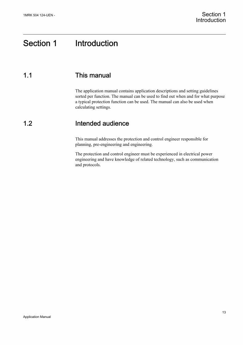
Figure 1: The intended use of manuals in different lifecycles
The engineering manual contains instructions on how to engineer the IEDs usingthe different tools in PCM600. The manual provides instructions on how to set up aPCM600 project and insert IEDs to the project structure. The manual alsorecommends a sequence for engineering of protection and control functions, LHMIfunctions as well as communication engineering for IEC 60870-5-103, IEC 61850and DNP3.
The installation manual contains instructions on how to install the IED. Themanual provides procedures for mechanical and electrical installation. The chaptersare organized in chronological order in which the IED should be installed.
The commissioning manual contains instructions on how to commission the IED.The manual can also be used by system engineers and maintenance personnel forassistance during the testing phase. The manual provides procedures for checkingof external circuitry and energizing the IED, parameter setting and configuration as
Section 1 1MRK 504 124-UEN -Introduction
14Application Manual
well as verifying settings by secondary injection. The manual describes the processof testing an IED in a substation which is not in service. The chapters are organizedin chronological order in which the IED should be commissioned.
The operation manual contains instructions on how to operate the IED once it hasbeen commissioned. The manual provides instructions for monitoring, controllingand setting the IED. The manual also describes how to identify disturbances andhow to view calculated and measured power grid data to determine the cause of afault.
The service manual contains instructions on how to service and maintain the IED.The manual also provides procedures for de-energizing, de-commissioning anddisposal of the IED.
The application manual contains application descriptions and setting guidelinessorted per function. The manual can be used to find out when and for what purposea typical protection function can be used. The manual can also be used whencalculating settings.
The technical manual contains application and functionality descriptions and listsfunction blocks, logic diagrams, input and output signals, setting parameters andtechnical data sorted per function. The manual can be used as a technical referenceduring the engineering phase, installation and commissioning phase, and duringnormal service.
The communication protocol manual describes a communication protocolsupported by the IED. The manual concentrates on vendor-specific implementations.
The point list manual describes the outlook and properties of the data pointsspecific to the IED. The manual should be used in conjunction with thecorresponding communication protocol manual.
The service manual is not available yet.
1.3.2 Document revision historyDocument revision/date Product series version History-/February 2011 1.1 First release
1.3.3 Related documentsDocuments related to RET650 Identity numberApplication manual 1MRK 504 124-UEN
Technical manual 1MRK 504 125-UEN
Commissioning manual 1MRK 504 126-UEN
Table continues on next page
1MRK 504 124-UEN - Section 1Introduction
15Application Manual
Documents related to RET650 Identity numberProduct Guide, configured 1MRK 504 127-BEN
Type test certificate 1MRK 504 127-TEN
650 series manuals Identity numberCommunication protocol manual, DNP3 1MRK 511 241-UEN
Communication protocol manual, IEC 61850 1MRK 511 242-UEN
Communication protocol manual, IEC 60870-5-103 1MRK 511 243-UEN
Point list manual, DNP3 1MRK 511 244-UEN
Engineering manual 1MRK 511 245-UEN
Operation manual 1MRK 500 093-UEN
Installation manual 1MRK 514 014-UEN
1.4 Symbols and conventions
1.4.1 Safety indication symbols
The electrical warning icon indicates the presence of a hazardwhich could result in electrical shock.
The warning icon indicates the presence of a hazard which couldresult in personal injury.
The caution icon indicates important information or warning relatedto the concept discussed in the text. It might indicate the presenceof a hazard which could result in corruption of software or damageto equipment or property.
The information icon alerts the reader of important facts andconditions.
The tip icon indicates advice on, for example, how to design yourproject or how to use a certain function.
Although warning hazards are related to personal injury, it is necessary tounderstand that under certain operational conditions, operation of damaged
Section 1 1MRK 504 124-UEN -Introduction
16Application Manual

equipment may result in degraded process performance leading to personal injuryor death. Therefore, comply fully with all warning and caution notices.
1.4.2 Manual conventionsConventions used in IED manuals. A particular convention may not be used in thismanual.
• Abbreviations and acronyms in this manual are spelled out in the glossary. Theglossary also contains definitions of important terms.
• Push button navigation in the LHMI menu structure is presented by using thepush button icons, for example:To navigate between the options, use and .
• HMI menu paths are presented in bold, for example:Select Main menu/Settings.
• LHMI messages are shown in Courier font, for example:To save the changes in non-volatile memory, select Yes and press .
• Parameter names are shown in italics, for example:The function can be enabled and disabled with the Operation setting.
• The ^ character in front of an input or output signal name in the function blocksymbol given for a function, indicates that the user can set an own signal namein PCM600.
• The * character after an input or output signal name in the function blocksymbol given for a function, indicates that the signal must be connected toanother function block in the application configuration to achieve a validapplication configuration.
1MRK 504 124-UEN - Section 1Introduction
17Application Manual

18
Section 2 Application
2.1 RET650 application
RET650 provides fast and selective protection, monitoring and control for two- andthree-winding transformers, autotransformers, generator-transformer units andshunt reactors. The transformer IED is designed to operate correctly over a widefrequency range in order to accommodate power system frequency variationsduring disturbances and generator start-up and shut-down.
A very fast differential protection function, with automatic CT ratio matching andvector group compensation, makes this IED the ideal solution even for the mostdemanding applications. Since RET650 has very low requirements on the mainCTs, no interposing CTs are required. The differential protection function isprovided with 2nd harmonic and wave-block restraint features to avoid tripping formagnetizing inrush current, and 5th harmonic restraint to avoid tripping foroverexcitation.
The differential function offers a high sensitivity for low-level internal faults. Theunique and innovative sensitive differential protection feature of the RET650provides the best possible coverage for winding internal turn-to-turn faults, basedon well-known theory of symmetrical components .
Low impedance restricted earth-fault protection function are available ascomplimentary sensitive and fast main protection against winding earth faults. Thisfunction includes a directional zero-sequence current criterion for additional security.
Tripping from Pressure relief/Buchholz and temperature devices can be donethrough the transformer IED where pulsing, lock-out contact output and so on, isperformed. The binary inputs are heavily stabilized against disturbance to preventincorrect operations at for example, dc system capacitive discharges or DC earthfaults.
Versatile phase, earth, negative and zero sequence overcurrent functions, whichcan be made directional, provide further alternative backup protection. Thermaloverload with two time-constants, volts per hertz, over/under voltage are alsoavailable.
A built-in disturbance and event recorders provide valuable data to the user aboutstatus and operation for post-fault disturbance analysis.
Breaker failure protection allows high speed back-up tripping of surroundingbreakers.
1MRK 504 124-UEN - Section 2Application
19Application Manual
Disturbance recording is available to allow independent post-fault analysis afterprimary disturbances.
Three packages have been defined for the following applications:
• Two-winding transformer in single breaker arrangements (A01)• Three-winding transformer in single breaker arrangements (A05)• Tap changer control (A07)
The packages are configured and ready for direct use. Analog and tripping IO hasbeen pre-defined for basic use. Other signals need to be applied as required foreach application.
The graphical configuration tool ensures simple and fast testing and commissioning.
Section 2 1MRK 504 124-UEN -Application
20Application Manual

T2W PDIF
87T 3Id/I
CC RBRF
50BF 3I> BF
CC RBRF
50BF 3I> BF
OC4 PTOC
50/51 3I>
OC4 PTOC
51/67 3I>
CC RPLD
52PD PD
EF4 PTOC
51N IN>
CC RPLD
52PD PD
TR PTTR
49 Ith
C MSQI
Meter.
V MMXU
Meter.
C MMXU
Meter.
CV MMXN
Meter.
TCS SCBR
Cond
TCS SCBR
Cond
SPVN ZBAT
Cond
TR8 ATCC
90 U
TCM YLTC
84
UV2 PTUV
27 U<
OV2 PTOV
59 U>
PH PIOC
50 3I>>
TR PTTR
49 Ith
REF PDIF
87N IdN/I
Other configured functions
REF PDIF
87N IdN/I
EF4 PTOC
51N/67N IN>
DRP RDRE
Mont.
YY
¨
ROV2 PTOV
59N 3U0>
RET650 A01 - 2 Winding Transformer protection 10AI (8I+2U)
20 MVA110±11*1.5% / 21 kV
105 / 550 AYNd5
20 kV Bus
110 kV Bus
200/1
600/120kV/100V
200/1
600/1
IEC61850
ANSI IEC
Function Enabled in Settings
IEC61850
ANSI IEC
Function Disabled in Settings
W1
W2
IEC09000645-2-en.vsd
IEC09000645 V2 EN
Figure 2: A typical protection application for a two-winding transformer insingle breaker arrangement
1MRK 504 124-UEN - Section 2Application
21Application Manual

RET650 A05 - 3 Winding Transformer protection 20AI 2*(6I+4U)
W1
T3W PDIF
87T 3Id/I
CC RBRF
50BF 3I> BF
CC RBRF
50BF 3I> BF
OC4 PTOC
50/51 3I>
OC4 PTOC
51/67 3I>
CC RPLD
52PD PD
CC RBRF
50BF 3I> BF
CC RPLD
52PD PD
EF4 PTOC
51N IN>
CC RPLD
52PD PD
TR PTTR
49 Ith
TR PTTR
49 Ith
V MSQI
Meter.
C MSQI
Meter.
V MMXU
Meter.
C MMXU
Meter.
CV MMXN
Meter.
V MSQI
Meter.
C MSQI
Meter.
V MMXU
Meter.
C MMXU
Meter.
CV MMXN
Meter.
TCS SCBR
Cond
TCS SCBR
Cond
TCS SCBR
Cond
SPVN ZBAT
Cond
TR8 ATCC
90 U
TCM YLTC
84
UV2 PTUV
27 U<
OV2 PTOV
59 U>
PH PIOC
50 3I>>
TR PTTR
49 Ith
REF PDIF
87N IdN/I
Other configured functions
REF PDIF
87N IdN/I
REF PDIF
87N IdN/I
OEX PVPH
24 U/f>
OC4 PTOC
51/67 3I>
EF4 PTOC
51N/67N IN>
EF4 PTOC
51N/67N IN>
DRP RDRE
Mont.
CV MMXN
Meter.
YY
¨
ROV2 PTOV
59N 3UO>
35 kV Bus
110 kV Bus
10 kV Bus
IEC61850
ANSI IEC
Function Enabled in Settings
IEC61850
ANSI IEC
Function Disabled in Settings
Transformer Data:40/40/15 MVA
110±11*1.5% / 36.75 / 10.5 kV210/628/825 A
YNyn0d5
110kV/100V
300/1
1000/1
800/1
800/1
300/1
10kV/100V
35kV/100V
1000/1W3 W2
IEC09000646-2-en.vsd
IEC09000646 V2 EN
Figure 3: A typical protection application for a three-winding transformer insingle breaker arrangement
Section 2 1MRK 504 124-UEN -Application
22Application Manual
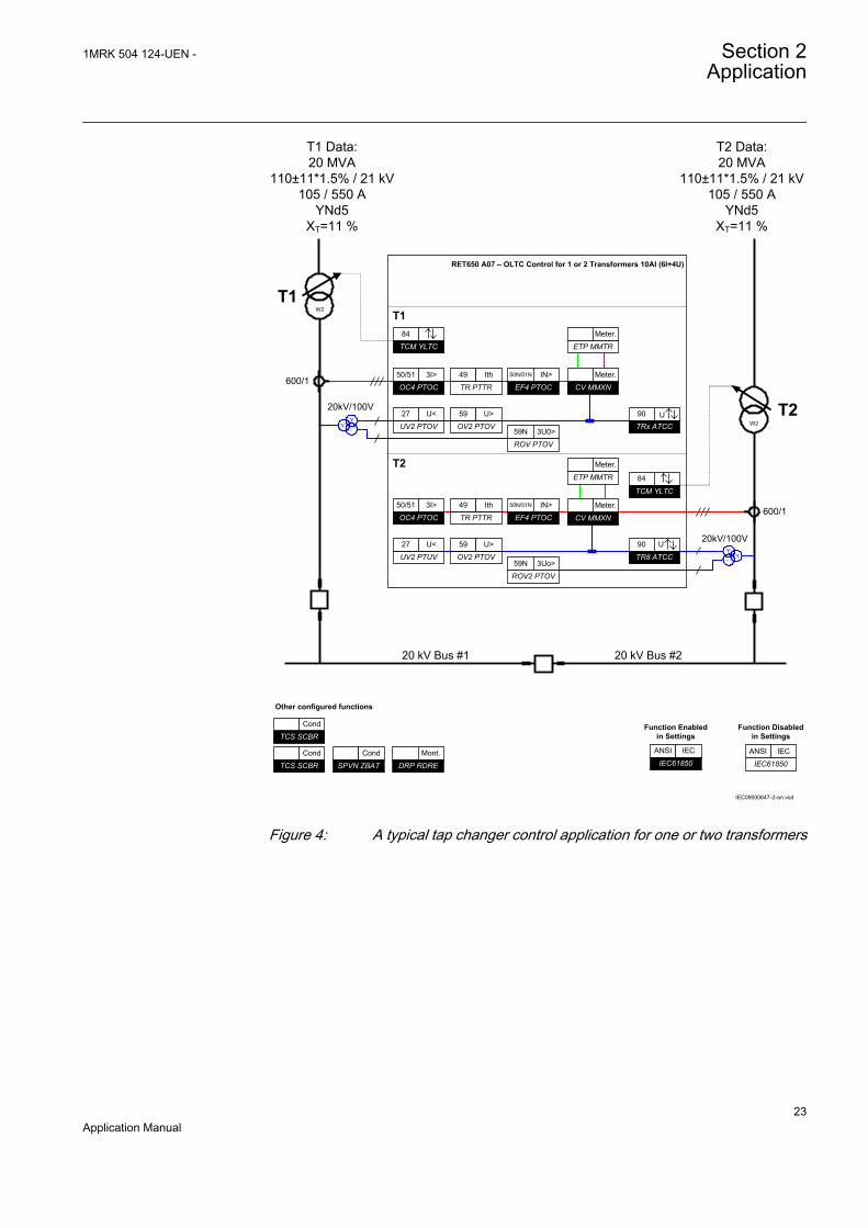
RET650 A07 – OLTC Control for 1 or 2 Transformers 10AI (6I+4U)
TR PTTR
49 Ith
EF4 PTOC
50N/51N IN>
CV MMXN
Meter.
T1
OC4 PTOC
50/51 3I>
ETP MMTR
Meter.
ROV PTOV
59N 3U0>
T2TRx ATCC
90 UUV2 PTOV
27 U<
OV2 PTOV
59 U>
TR PTTR
49 Ith
EF4 PTOC
50N/51N IN>
CV MMXN
Meter.OC4 PTOC
50/51 3I>
ETP MMTR
Meter.
ROV2 PTOV
59N 3Uo>TR8 ATCC
90 U
UV2 PTUV
27 U<
OV2 PTOV
59 U>
T1
T2
YY
°
YY
°
TCM YLTC
84
TCM YLTC
84
TCS SCBR
Cond
TCS SCBR
Cond
SPVN ZBAT
Cond
Other configured functions
DRP RDRE
Mont.
T1 Data:20 MVA
110±11*1.5% / 21 kV105 / 550 A
YNd5XT=11 %
T2 Data:20 MVA
110±11*1.5% / 21 kV105 / 550 A
YNd5XT=11 %
20 kV Bus #1 20 kV Bus #2
IEC61850
ANSI IEC
Function Enabled in Settings
IEC61850
ANSI IEC
Function Disabled in Settings
600/1
20kV/100V
600/1
20kV/100V
W2
W2
IEC09000647-2-en.vsd
IEC09000647 V2 EN
Figure 4: A typical tap changer control application for one or two transformers
1MRK 504 124-UEN - Section 2Application
23Application Manual

2.2 Available functions
2.2.1 Main protection functionsIEC 61850/Function blockname
ANSI Function description Transformer
RET
650
(A01
)2W
/1C
B
RET
650
(A05
)3W
/1C
B
RET
650
(A07
)O
LTC
Differential protection
T2WPDIF 87T Transformer differential protection, two winding 1
T3WPDIF 87T Transformer differential protection, three winding 1
REFPDIF 87N Restricted earth fault protection, low impedance 2 3
HZPDIF 87 1Ph High impedance differential protection 2 2
2.2.2 Back-up protection functionsIEC 61850/Function blockname
ANSI Function description Transformer
RET
650
(A01
)2W
/1C
B
RET
650
(A05
)3W
/1C
B
RET
650
(A07
)O
LTC
Current protection
PHPIOC 50 Instantaneous phase overcurrent protection 2 3
OC4PTOC 51/67 Four step directional phase overcurrent protection 2 3 2
EFPIOC 50N Instantaneous residual overcurrent protection 2 3
EF4PTOC 51N/67N Four step directional residual overcurrent protection 2 3 2
TRPTTR 49 Thermal overload protection, two time constants 2 3 2
CCRBRF 50BF Breaker failure protection 2 3
CCRPLD 52PD Pole discordance protection 2 3
GUPPDUP 37 Directional underpower protection 1 1 2
GOPPDOP 32 Directional overpower protection 1 1 2
DNSPTOC 46 Negative sequence based overcurrent function 1 2
Voltage protection
UV2PTUV 27 Two step undervoltage protection 1 1 2
OV2PTOV 59 Two step overvoltage protection 1 1 2
ROV2PTOV 59N Two step residual overvoltage protection 1 1 2
OEXPVPH 24 Overexcitation protection 1
Frequency protection
Table continues on next page
Section 2 1MRK 504 124-UEN -Application
24Application Manual
IEC 61850/Function blockname
ANSI Function description Transformer
RET
650
(A01
)2W
/1C
B
RET
650
(A05
)3W
/1C
B
RET
650
(A07
)O
LTC
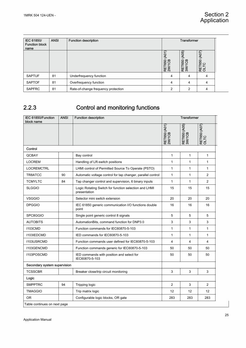
SAPTUF 81 Underfrequency function 4 4 4
SAPTOF 81 Overfrequency function 4 4 4
SAPFRC 81 Rate-of-change frequency protection 2 2 4
2.2.3 Control and monitoring functionsIEC 61850/Functionblock name
ANSI Function description Transformer
RET
650
(A01
)2W
/1C
B
RET
650
(A05
)3W
/1C
B
RET
650
(A07
)O
LTC
Control
QCBAY Bay control 1 1 1
LOCREM Handling of LR-switch positions 1 1 1
LOCREMCTRL LHMI control of Permitted Source To Operate (PSTO) 1 1 1
TR8ATCC 90 Automatic voltage control for tap changer, parallel control 1 1 2
TCMYLTC 84 Tap changer control and supervision, 6 binary inputs 1 1 2
SLGGIO Logic Rotating Switch for function selection and LHMIpresentation
15 15 15
VSGGIO Selector mini switch extension 20 20 20
DPGGIO IEC 61850 generic communication I/O functions doublepoint
16 16 16
SPC8GGIO Single point generic control 8 signals 5 5 5
AUTOBITS AutomationBits, command function for DNP3.0 3 3 3
I103CMD Function commands for IEC60870-5-103 1 1 1
I103IEDCMD IED commands for IEC60870-5-103 1 1 1
I103USRCMD Function commands user defined for IEC60870-5-103 4 4 4
I103GENCMD Function commands generic for IEC60870-5-103 50 50 50
I103POSCMD IED commands with position and select forIEC60870-5-103
50 50 50
Secondary system supervision
TCSSCBR Breaker close/trip circuit monitoring 3 3 3
Logic
SMPPTRC 94 Tripping logic 2 3 2
TMAGGIO Trip matrix logic 12 12 12
OR Configurable logic blocks, OR gate 283 283 283
Table continues on next page
1MRK 504 124-UEN - Section 2Application
25Application Manual
IEC 61850/Functionblock name
ANSI Function description Transformer
RET
650
(A01
)2W
/1C
B
RET
650
(A05
)3W
/1C
B
RET
650
(A07
)O
LTC
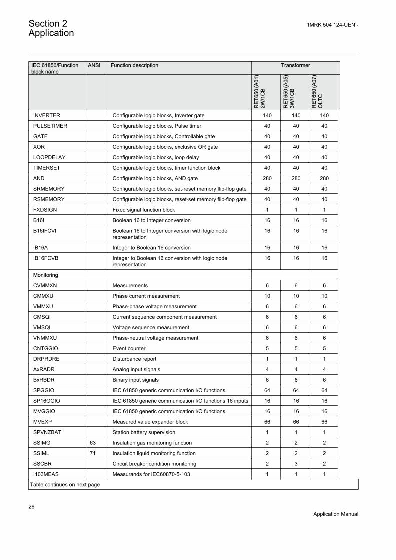
INVERTER Configurable logic blocks, Inverter gate 140 140 140
PULSETIMER Configurable logic blocks, Pulse timer 40 40 40
GATE Configurable logic blocks, Controllable gate 40 40 40
XOR Configurable logic blocks, exclusive OR gate 40 40 40
LOOPDELAY Configurable logic blocks, loop delay 40 40 40
TIMERSET Configurable logic blocks, timer function block 40 40 40
AND Configurable logic blocks, AND gate 280 280 280
SRMEMORY Configurable logic blocks, set-reset memory flip-flop gate 40 40 40
RSMEMORY Configurable logic blocks, reset-set memory flip-flop gate 40 40 40
FXDSIGN Fixed signal function block 1 1 1
B16I Boolean 16 to Integer conversion 16 16 16
B16IFCVI Boolean 16 to Integer conversion with logic noderepresentation
16 16 16
IB16A Integer to Boolean 16 conversion 16 16 16
IB16FCVB Integer to Boolean 16 conversion with logic noderepresentation
16 16 16
Monitoring
CVMMXN Measurements 6 6 6
CMMXU Phase current measurement 10 10 10
VMMXU Phase-phase voltage measurement 6 6 6
CMSQI Current sequence component measurement 6 6 6
VMSQI Voltage sequence measurement 6 6 6
VNMMXU Phase-neutral voltage measurement 6 6 6
CNTGGIO Event counter 5 5 5
DRPRDRE Disturbance report 1 1 1
AxRADR Analog input signals 4 4 4
BxRBDR Binary input signals 6 6 6
SPGGIO IEC 61850 generic communication I/O functions 64 64 64
SP16GGIO IEC 61850 generic communication I/O functions 16 inputs 16 16 16
MVGGIO IEC 61850 generic communication I/O functions 16 16 16
MVEXP Measured value expander block 66 66 66
SPVNZBAT Station battery supervision 1 1 1
SSIMG 63 Insulation gas monitoring function 2 2 2
SSIML 71 Insulation liquid monitoring function 2 2 2
SSCBR Circuit breaker condition monitoring 2 3 2
I103MEAS Measurands for IEC60870-5-103 1 1 1
Table continues on next page
Section 2 1MRK 504 124-UEN -Application
26Application Manual
IEC 61850/Functionblock name
ANSI Function description Transformer
RET
650
(A01
)2W
/1C
B
RET
650
(A05
)3W
/1C
B
RET
650
(A07
)O
LTC
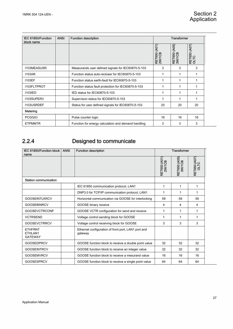
I103MEASUSR Measurands user defined signals for IEC60870-5-103 3 3 3
I103AR Function status auto-recloser for IEC60870-5-103 1 1 1
I103EF Function status earth-fault for IEC60870-5-103 1 1 1
I103FLTPROT Function status fault protection for IEC60870-5-103 1 1 1
I103IED IED status for IEC60870-5-103 1 1 1
I103SUPERV Supervison status for IEC60870-5-103 1 1 1
I103USRDEF Status for user defined signals for IEC60870-5-103 20 20 20
Metering
PCGGIO Pulse counter logic 16 16 16
ETPMMTR Function for energy calculation and demand handling 3 3 3
2.2.4 Designed to communicateIEC 61850/Function blockname
ANSI Function description Transformer
R
ET65
0 (A
01)
2W/1
CB
RET
650
(A05
)3W
/1C
B
RET
650
(A07
)O
LTC
Station communication
IEC 61850 communication protocol, LAN1 1 1 1
DNP3.0 for TCP/IP communication protocol, LAN1 1 1 1
GOOSEINTLKRCV Horizontal communication via GOOSE for interlocking 59 59 59
GOOSEBINRCV GOOSE binary receive 4 4 4
GOOSEVCTRCONF GOOSE VCTR configuration for send and receive 1 1 1
VCTRSEND Voltage control sending block for GOOSE 1 1 1
GOOSEVCTRRCV Voltage control receiving block for GOOSE 3 3 3
ETHFRNTETHLAN1GATEWAY
Ethernet configuration of front port, LAN1 port andgateway
GOOSEDPRCV GOOSE function block to receive a double point value 32 32 32
GOOSEINTRCV GOOSE function block to receive an integer value 32 32 32
GOOSEMVRCV GOOSE function block to receive a mesurand value 16 16 16
GOOSESPRCV GOOSE function block to receive a single point value 64 64 64
1MRK 504 124-UEN - Section 2Application
27Application Manual
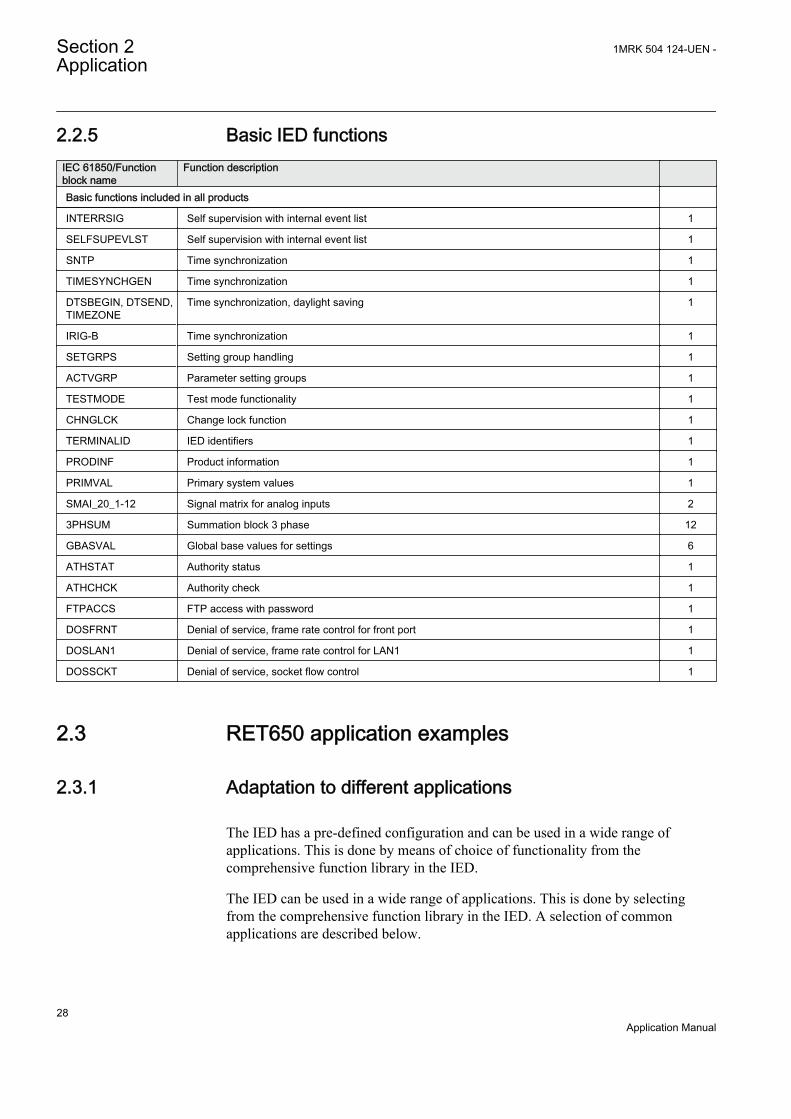
2.2.5 Basic IED functionsIEC 61850/Functionblock name
Function description
Basic functions included in all products
INTERRSIG Self supervision with internal event list 1
SELFSUPEVLST Self supervision with internal event list 1
SNTP Time synchronization 1
TIMESYNCHGEN Time synchronization 1
DTSBEGIN, DTSEND,TIMEZONE
Time synchronization, daylight saving 1
IRIG-B Time synchronization 1
SETGRPS Setting group handling 1
ACTVGRP Parameter setting groups 1
TESTMODE Test mode functionality 1
CHNGLCK Change lock function 1
TERMINALID IED identifiers 1
PRODINF Product information 1
PRIMVAL Primary system values 1
SMAI_20_1-12 Signal matrix for analog inputs 2
3PHSUM Summation block 3 phase 12
GBASVAL Global base values for settings 6
ATHSTAT Authority status 1
ATHCHCK Authority check 1
FTPACCS FTP access with password 1
DOSFRNT Denial of service, frame rate control for front port 1
DOSLAN1 Denial of service, frame rate control for LAN1 1
DOSSCKT Denial of service, socket flow control 1
2.3 RET650 application examples
2.3.1 Adaptation to different applications
The IED has a pre-defined configuration and can be used in a wide range ofapplications. This is done by means of choice of functionality from thecomprehensive function library in the IED.
The IED can be used in a wide range of applications. This is done by selectingfrom the comprehensive function library in the IED. A selection of commonapplications are described below.
Section 2 1MRK 504 124-UEN -Application
28Application Manual
• Application 1: Two-winding HV/MV, Y/Δ-transformer; HV:solidly earthed,MV:high impedance earthed
• Application 2: Two-winding HV/MV, Y/Y-transformer; HV:solidly earthed,MV:high impedance earthed
• Application 3: Three-winding HV/MV1/MV2, Y/Y/Δ- transformer;HV:solidly earthed, MV1:solidly earthed, MV2:high impedance earthed
• Application 4: Three-winding HV/MV1/MV2, Y/Y/Δ-transformer; HV:solidlyearthed, MV1:solidly earthed, MV2:solidly earthed
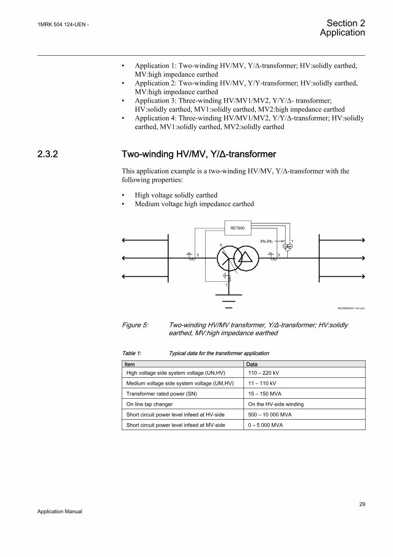
2.3.2 Two-winding HV/MV, Y/Δ-transformerThis application example is a two-winding HV/MV, Y/Δ-transformer with thefollowing properties:
• High voltage solidly earthed• Medium voltage high impedance earthed
11
1
33
IEC09000435-1-en.vsd
RET650
Ph-Ph
IEC09000435 V1 EN
Figure 5: Two-winding HV/MV transformer, Y/Δ-transformer; HV:solidlyearthed, MV:high impedance earthed
Table 1: Typical data for the transformer application
Item DataHigh voltage side system voltage (UN,HV) 110 – 220 kV
Medium voltage side system voltage (UM,HV) 11 – 110 kV
Transformer rated power (SN) 15 – 150 MVA
On line tap changer On the HV-side winding
Short circuit power level infeed at HV-side 500 – 10 000 MVA
Short circuit power level infeed at MV-side 0 – 5 000 MVA
1MRK 504 124-UEN - Section 2Application
29Application Manual
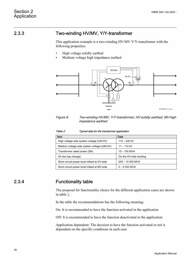
2.3.3 Two-winding HV/MV, Y/Y-transformerThis application example is a two-winding HV/MV Y/Y-transformer with thefollowing properties:
• High voltage solidly earthed• Medium voltage high impedance earthed
1
33
1
1
1
IEC09000436-1-en.vsd
Ph-Ph
RET650
IEC09000436 V1 EN
Figure 6: Two-winding HV/MV, Y/Y-transformer; HV:solidly earthed, MV:highimpedance earthed
Table 2: Typical data for the transformer application
Item DataHigh voltage side system voltage (UN,HV) 110 – 220 kV
Medium voltage side system voltage (UM,HV) 11 – 110 kV
Transformer rated power (SN) 15 – 150 MVA
On line tap changer On the HV-side winding
Short circuit power level infeed at HV-side 500 – 10 000 MVA
Short circuit power level infeed at MV-side 0 – 5 000 MVA
2.3.4 Functionality tableThe proposal for functionality choice for the different application cases are shownin table 3.
In the table the recommendations has the following meaning:
On: It is recommended to have the function activated in the application
Off: It is recommended to have the function deactivated in the application
Application dependent: The decision to have the function activated or not isdependent on the specific conditions in each case
Section 2 1MRK 504 124-UEN -Application
30Application Manual

Application 1 and Application 2 in table 3 are according toapplication examples given in previous sections.
Table 3: Selection of functions in different applications
Function Application 1 Application 2Transformer differential protection, twowinding T2WPDIF
On On
Restricted earth fault protection REFPDIF(instance 1)
On On
Restricted earth fault protection REFPDIF(instance 2)
Application dependent Application dependent
Instantaneous phase overcurrent protectionPHPIOC (instance 1 on HV side)
On On
Instantaneous phase overcurrent protectionPHPIOC (instance 2 on MV side)
Off Off
Four step phase overcurrent protectionOC4PTOC (instance 1 on HV-side)
On On
Four step phase overcurrent protectionOC4PTOC (instance 2 on MV-side)
On On
Instantaneous residual overcurrentprotection EFPIOC (instance 1 on HV-sideneutral point)
On On
Instantaneous residual overcurrentprotection EFPIOC (instance 2 on MV-sideneutral point)
Off Off
Four step residual overcurrent protectionEF4PTOC (instance 1 on HV-side)
On On
Four step residual overcurrent protectionEF4PTOC (instance 2 on MV-side)
Application dependent Application dependent
Thermal overload protection TRPTTR(instance 1 on HV-side)
On On
Thermal overload protection, two timeconstants TRPTTR (instance 2 on MV-side)
Application dependent Application dependent
Breaker failure protection CCRBRF(instance 1 on HV-side)
On On
Breaker failure protection CCRBRF(instance 2 on MV-side)
On On
Pole discordance protection CCRPLD Application dependent Application dependent
Directional under-power protectionGUPPDUP
Application dependent Application dependent
Directional over-power protectionGOPPDOP
Application dependent Application dependent
Negative sequence based overcurrentprotection DNSPTOC
On On
Two step undervoltage protection UV2PTUV Application dependent Application dependent
Two step overvoltage protection OV2PTOV Application dependent Application dependent
Two step residual overvoltage protectionROV2PTOV
On On
Table continues on next page
1MRK 504 124-UEN - Section 2Application
31Application Manual

Function Application 1 Application 2Overexcitation protection OEXPVPH Off Off
Under frequency protection SAPTUF Application dependent Application dependent
Over frequency protection SAPTOF Application dependent Application dependent
Rate-of-change frequency protectionSAPFRC
Application dependent Application dependent
Breaker close/trip circuit monitoringTCSSCBR
On On
Automatic voltage control for tap changer,single control TR1ATCC
On On
2.3.5 Three-winding HV/MV1/MV2, Y/Y/Δ-transformerThis application example is a three-winding HV/MV1/MV2, Y/Y/Δ-transformerwith the following properties:
• High voltage solidly earthed• Medium voltage 1 solidly earthed• Medium voltage 2 high impedance earthed
IEC09000437-1-en.vsd
1
3
33
1
3
3
1
1
RET650
IEC09000437 V1 EN
Figure 7: Three-winding HV/MV1/MV2, Y/Y/Δ-transformer; HV:solidlyearthed, MV1:solidly earthed, MV2:high impedance earthed
Table 4: Typical data for the transformer application
Item DataHigh voltage side system voltage (UN,HV) 110 – 400 kV
Medium voltage side1 system voltage (UM1,HV) 11 – 110 kV
Medium voltage side2 system voltage (UM2,HV) 11 – 110 kV
Transformer rated power (SN) 25 – 500 MVA
Table continues on next page
Section 2 1MRK 504 124-UEN -Application
32Application Manual
Item DataOn line tap changer On the HV-side winding
Short circuit power level infeed at HV-side 500 – 10 000 MVA
Short circuit power level infeed at MV1-side 0 – 5 000 MVA
Short circuit power level infeed at MV2-side 0 – 5 000 MVA
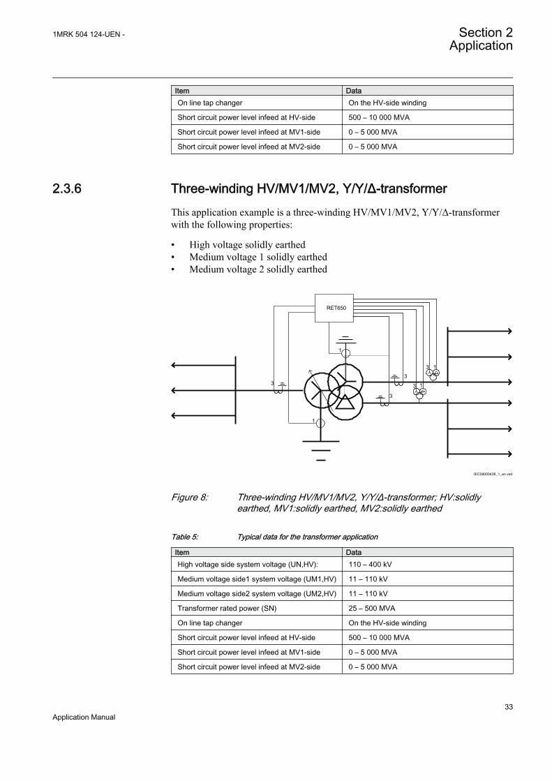
2.3.6 Three-winding HV/MV1/MV2, Y/Y/Δ-transformerThis application example is a three-winding HV/MV1/MV2, Y/Y/Δ-transformerwith the following properties:
• High voltage solidly earthed• Medium voltage 1 solidly earthed• Medium voltage 2 solidly earthed
IEC09000438_1_en.vsd
RET650
1
3
33
1
3
3
1
1
.
IEC09000438 V1 EN
Figure 8: Three-winding HV/MV1/MV2, Y/Y/Δ-transformer; HV:solidlyearthed, MV1:solidly earthed, MV2:solidly earthed
Table 5: Typical data for the transformer application
Item DataHigh voltage side system voltage (UN,HV): 110 – 400 kV
Medium voltage side1 system voltage (UM1,HV) 11 – 110 kV
Medium voltage side2 system voltage (UM2,HV) 11 – 110 kV
Transformer rated power (SN) 25 – 500 MVA
On line tap changer On the HV-side winding
Short circuit power level infeed at HV-side 500 – 10 000 MVA
Short circuit power level infeed at MV1-side 0 – 5 000 MVA
Short circuit power level infeed at MV2-side 0 – 5 000 MVA
1MRK 504 124-UEN - Section 2Application
33Application Manual

2.3.7 Functionality tableThe proposal for functionality choice for the different application cases are shownin table 6. In the table the recommendations has the following meaning:
On: It is recommended to have the function activated in the application
Off: It is recommended to have the function deactivated in the application
Application dependent: The decision to have the function activated or not isdependent on the specific conditions in each case
Application 3 and Application 4 in table 6 are according toapplication examples given in previous sections.
Table 6: Selection of functions in different applications
Function Application 3 Application 4Transformer differential protection, three winding T3WPDIF On On
Restricted earth fault protection REFPDIF (instance 1 on HV-side) On On
Restricted earth fault protection REFPDIF (instance 2 on MV1-side) On Application dependent
Restricted earth fault protection REFPDIF (instance 3 on MV2-side) Application dependent Application dependent
Instantaneous phase overcurrent protection PHPIOC (instance 1 on HV side) On On
Instantaneous phase overcurrent protection PHPIOC (instance 2 on MV1-side)
Off Off
Instantaneous phase overcurrent protection PHPIOC (instance 3 on MV2-side)
Off Off
Four step phase overcurrent protection OC4PTOC (instance 1 on HV-side) On On
Four step phase overcurrent protection OC4PTOC (instance 2 on MV1-side) On On
Four step phase overcurrent protection OC4PTOC (instance 3 on MV2-side) On On
Instantaneous residual overcurrent protection EFPIOC (instance 1 on HV-side)
On On
Instantaneous residual overcurrent protection EFPIOC (instance 2 on MV1-side)
Application dependent Application dependent
Instantaneous residual overcurrent protection EFPIOC (instance 3 on MV2-side)
Off Application dependent
Four step residual overcurrent protection EF4PTOC (HV side neutral point) On On
Four step residual overcurrent protection EF4PTOC (MV1 side neutral point) On On
Four step residual overcurrent protection EF4PTOC (MV2 side neutral point) Application dependent On
Thermal overload protection, two time constants TRPTTR (instance 1 on HV-side)
On On
Thermal overload protection, two time constants TRPTTR (instance 2 onMV1-side)
Application dependent Application dependent
Thermal overload protection, two time constants TRPTTR (instance 3 onMV2-side)
Application dependent Application dependent
Breaker failure protection CCRBRF (instance 1 on HV-side) On On
Table continues on next page
Section 2 1MRK 504 124-UEN -Application
34Application Manual

Function Application 3 Application 4Breaker failure protection CCRBRF (instance 2 on MV1-side) On On
Breaker failure protection CCRBRF (instance 3 on MV2-side) On On
Pole discordance protection CCRPLD Application dependent Application dependent
Directional under-power protection GUPPDUP Application dependent Application dependent
Directional over-power protection GOPPDOP Application dependent Application dependent
Two step undervoltage protection UV2PTUV Application dependent Application dependent
Two step overvoltage protection OV2PTOV Application dependent Application dependent
Two step residual overvoltage protection ROV2PTOV On On
Overexcitation protection OEXPVPH On On
Under frequency protection SAPTUF Application dependent Application dependent
Over frequency protection SAPTOF Application dependent Application dependent
Rate-of-change of frequency protection SAPFRC Application dependent Application dependent
Breaker close/trip circuit monitoring TCSSCBR On On
Automatic voltage control for tap changer, single control TR1ATCC On On
1MRK 504 124-UEN - Section 2Application
35Application Manual

36
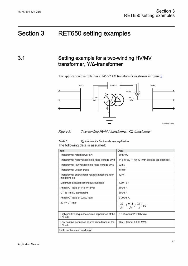
Section 3 RET650 setting examples
3.1 Setting example for a two-winding HV/MVtransformer, Y/Δ-transformer
The application example has a 145/22 kV transformer as shown in figure 9.
11
1
33
Ph-Ph
145 kV 22 kV
IEC09000446-1-en.vsd
RET650
IEC09000446 V1 EN
Figure 9: Two-winding HV/MV transformer, Y/Δ-transformer
Table 7: Typical data for the transformer applicationThe following data is assumed:Item DataTransformer rated power SN 60 MVA
Transformer high voltage side rated voltage UN1 145 kV ±9 · 1.67 % (with on load tap changer)
Transformer low voltage side rated voltage UN2 22 kV
Transformer vector group YNd11
Transformer short circuit voltage at tap changermid point: ek
12 %
Maximum allowed continuous overload 1,30 · SN
Phase CT ratio at 145 kV level 300/1 A
CT at 145 kV earth point 300/1 A
Phase CT ratio at 22 kV level 2 000/1 A
22 kV VT ratio/22
30 11
3. 0 11
3./ kV
High positive sequence source impedance at theHV side
j10 Ω (about 2 100 MVA)
Low positive sequence source impedance at theHV side
j3.5 Ω (about 6 000 MVA)
Table continues on next page
1MRK 504 124-UEN - Section 3RET650 setting examples
37Application Manual

Item DataHigh zero sequence source impedance at theHV side
j20 Ω
Low zero sequence source impedance at the HVside
j15 Ω
Positive sequence source impedance at the LVside
∞ (no generation in the 22 kV network)
Only settings that need adjustment due to the specific applicationare described in setting examples. It is recommended to keep thedefault values for all settings that are not described. Refer toTechnical manual for setting tables for each protection and controlfunction.
Refer to setting guideline section in Application manual forguidelines on how to set functions that are not presented in settingexamples.
Use parameter setting tool in PCM600 to set the IED according tocalculations for the particular application.
3.1.1 Calculating general settings for analogue inputs 8I 2UThe analogue input has the capability of 8 current inputs (1 A) and 2 voltage inputs.
The 145 kV current CTs (three phase current transformer group) are connected toinputs 1 – 3 (L1, L2, L3).
The 22 kV current CTs (three phase current transformer group) are connected toinputs 4 – 6 (L1, L2, L3).
The 145 kV neutral point CT is connected to input 7 (IN).
The input 8 is not used. The input is used for connection of low voltage side CT(not in this application)
The 22 kV phase-to-phase (L1 – L2) VT is connected to input 9.
The 22 kV open delta connected VT (residual voltage) is connected to input 10.
1. Set the 145 kV current transformer input 1.1.1. Set CTStarPoint1 to ToObject
Section 3 1MRK 504 124-UEN -RET650 setting examples
38Application Manual
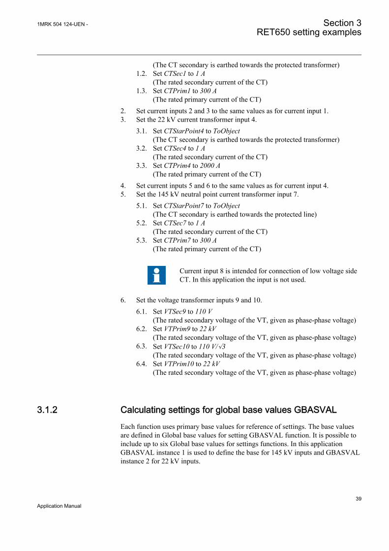
(The CT secondary is earthed towards the protected transformer)1.2. Set CTSec1 to 1 A
(The rated secondary current of the CT)1.3. Set CTPrim1 to 300 A
(The rated primary current of the CT)2. Set current inputs 2 and 3 to the same values as for current input 1.3. Set the 22 kV current transformer input 4.
3.1. Set CTStarPoint4 to ToObject(The CT secondary is earthed towards the protected transformer)
3.2. Set CTSec4 to 1 A(The rated secondary current of the CT)
3.3. Set CTPrim4 to 2000 A(The rated primary current of the CT)
4. Set current inputs 5 and 6 to the same values as for current input 4.5. Set the 145 kV neutral point current transformer input 7.
5.1. Set CTStarPoint7 to ToObject(The CT secondary is earthed towards the protected line)
5.2. Set CTSec7 to 1 A(The rated secondary current of the CT)
5.3. Set CTPrim7 to 300 A(The rated primary current of the CT)
Current input 8 is intended for connection of low voltage sideCT. In this application the input is not used.
6. Set the voltage transformer inputs 9 and 10.6.1. Set VTSec9 to 110 V
(The rated secondary voltage of the VT, given as phase-phase voltage)6.2. Set VTPrim9 to 22 kV
(The rated secondary voltage of the VT, given as phase-phase voltage)6.3. Set VTSec10 to 110 V/√3
(The rated secondary voltage of the VT, given as phase-phase voltage)6.4. Set VTPrim10 to 22 kV
(The rated secondary voltage of the VT, given as phase-phase voltage)
3.1.2 Calculating settings for global base values GBASVALEach function uses primary base values for reference of settings. The base valuesare defined in Global base values for setting GBASVAL function. It is possible toinclude up to six Global base values for settings functions. In this applicationGBASVAL instance 1 is used to define the base for 145 kV inputs and GBASVALinstance 2 for 22 kV inputs.
1MRK 504 124-UEN - Section 3RET650 setting examples
39Application Manual

For transformer protection it is recommended to set the base parameters accordingto the power transformer primary rated values:
1. Set Global Base 11.1. Set IBase to 239 A1.2. Set UBase to 145 kV1.3. Set SBase to 60 MVA (SBase=√3·UBase·IBase)
2. Set Global Base 22.1. Set IBase to 1575 A2.2. Set UBase to 22 kV2.3. Set SBase to 60 MVA (SBase=√3·UBase·IBase)
The GlobalBaseSel setting in a protection and control functionreferences a Global base values for setting function for reference ofprimary values.
3.1.3 Calculating settings for transformer differential protectionT2WPDIF
1. Set GlobalBaseSelW1 to 1 (HV)2. Set GlobalBaseSelW2 to 2 (LV)
To relate the settings to the rated data of the transformer the two windingsshould be related to Global base values for settings function 1 (HV-side) and2 (LV-side).
3. Set the vector group of the transformer3.1. Set ConnectedTypeW1 to WYE (Y)3.2. Set ConnectedTypeW2 to Delta (D)3.3. Set ClockNumberW2 to 11
4. Set system residual current elimination4.1. Set ZSCurrSutrW1 to On4.2. Set ZSCurrSutrW2 to Off
The transformer is solidly earthed at the 145 kV side. In case of earth-fault inthe 145 kV system residual current flows from the transformer. This residualcurrent is seen as a differential current even if there is no internal transformerfault. To prevent unwanted trip at external earth-fault there is a functionwhere the zero sequence current is eliminated from the measured transformercurrent. This elimination is only needed for the solidly earthed winding.
5. Set I2/I1Ratio to 15 % (default)When the transformer is energized an inrush current occurs. This current isseen as a differential current. With a combination of the second harmonicrestraint and the waveform restraint methods it is possible to get a protection
Section 3 1MRK 504 124-UEN -RET650 setting examples
40Application Manual

with high security and stability against inrush effects and at the same timemaintain high performance in case of heavy internal faults even if the currenttransformers are saturated. Both these restraint methods are used. It isrecommended to set parameter I2/I1Ratio = 15% as default value in case nospecial reasons exist to choose other value.
6. Set I5/I1Ratio to 25 % (default)When the transformer is overexcited due to high voltage and/or low networkfrequency, the excitation current increases significantly. This current is seenas a differential current. The differential protection function is provided witha fifth harmonic restraint to prevent the protection from operation during anoverexcitation condition of the power transformer. It is recommended to setparameter I5/I1Ratio = 25% as default value in case no special reasons existto choose other value.
7. Set CrossBlockEn to OnIf any the above mentioned restrain functions (waveform restrain, secondharmonic restrain or fifth harmonic restrain) is activated in one phase, cross-blocking can be used to prevent operation of the differential protection also inthe other phases. It is recommended to set the cross-blocking on.
8. Set restrain characteristics8.1. Set EndSection1 to 1.25 IBase8.2. Set EndSection2 to 3 IBase8.3. Set SlopeSection2 to 40 %8.4. Set SlopeSection3 to 80 %
The characteristic of the restrained and unrestrained differential protection isshown in figure 10. The differential current limit for operation of theprotection is shown as a function of the restrain current. The restrain currentis equal to highest transformer phase current. The restrain characteristic isdefined by the parameters: IdMin, EndSection1, EndSection2, SlopeSection2and SlopeSection3. The settings of EndSection1, EndSection2, SlopeSection2and SlopeSection3 are defined as advanced and the default values arerecommended.
1MRK 504 124-UEN - Section 3RET650 setting examples
41Application Manual

Section 1
Operate conditionally
UnrestrainedLimit
Section 2 Section 3
Restrain
Operate unconditionally
5
4
3
2
1
00 1 2 3 4 5
IdMin
EndSection1
EndSection2restrain current
[ times I1r ]
operate current[ times I1r ]
SlopeSection2
SlopeSection3
en05000187.vsdGUID-F6F9E16D-A762-4518-A9E1-A4B2A962821B V1 EN
Figure 10: Transformer differential protection operation characteristic
9. Set IdMin to ≥0.3 IBaseDuring normal operation there is a ”false” differential current measured bythe protection due to the following:• Deviation tap changer position compared to the nominal transformer ratio• Difference in current transformer error
The measured differential current at tap changer position in the extremepositions can be calculated:At the tap position giving the lowest LV voltage the transformer ratio is166.8/22 kV. At 1.25 times the rated power (EndSection1) the 145 kV currentis:
1.25 60 0.2603 166.8HVI kA×
= =×
GUID-5461E726-C83D-4B02-B2A6-E3F376308529 V1 EN (Equation 1)
This corresponds to 1.088 times the rated current. The low voltage sidecurrent is 1.25 times the rated current and thus the differential current is about0.16 times the rated transformer current.At the tap position giving the highest LV voltage the transformer ratio is123.2/22 kV. At 1.25 times the rated power (EndSection1) the 145 kV currentis:
Section 3 1MRK 504 124-UEN -RET650 setting examples
42Application Manual

1.25 60 0.3523 123.2HVI kA×
= =×
GUID-6C914C3F-86A8-450C-9CCF-16BCA07A48E2 V1 EN (Equation 2)
This corresponds to 1.471 times the rated current. The low voltage sidecurrent is 1.25 times the rated current and thus the differential current is about0.22 times the rated transformer current.The current transformers class is 5P giving a maximum amplitude error of 1% and maximum phase displacement of 60 minutes. To assure that the loadcurrent does not cause unwanted operation IdMin is set to 0.25 times the ratedtransformer current.
10. Set IdUnre to 10.0 IBaseThe unrestrained differential protection function is operated without anystabilization. The setting principle is that the unrestrained function shall onlybe able to detect internal faults. This means that the current setting shall belarger than the largest current through the transformer at external faults. Avery simple way to estimate this current is as:
1 1 8.330.12k
IdUnre IBase IBase IBasee
³ × = × = ×
GUID-D44EC374-13ED-4E91-A420-F9C7460F71C2 V2 EN (Equation 3)
If the feeding network is considered and a three-phase-fault at the low voltageside of the transformer is calculated, the following current results through thetransformer (145 kV level):
2145 145 1 83
3 1453 3 5 0 1260
net TI . kA
( Z Z )( . . )
= = =× +
× + ×
GUID-D49C58EF-F9FD-4BAD-943A-55C186968C2F V2 EN (Equation 4)
This corresponds to 7.6 times the transformer rated current. In the settingthere should also be consideration to the influence from fault current DC-component.
11. Set NegSeqDiffEn, IMinNegSeq and NegSeqROA11.1. Set NegSeqDiffEn to On (default)11.2. Set IMinNegSeq to >0.04 IBase (default)11.3. Set NegSeqROA to 60º (default)
The transformer differential protection also has external/internal faultdiscrimination, based on negative sequence current. The settings ofNegSeqDiffEn, IMinNegSeq and NegSeqROA are defined as advanced and thedefault values are recommended.
1MRK 504 124-UEN - Section 3RET650 setting examples
43Application Manual
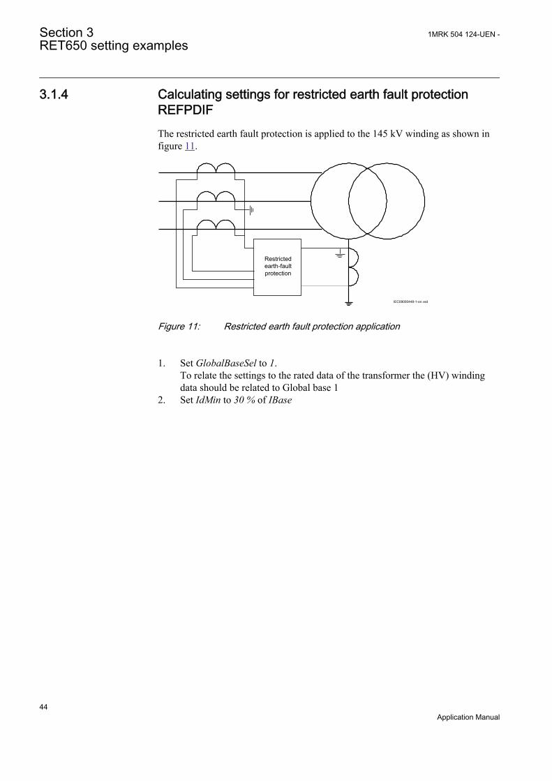
3.1.4 Calculating settings for restricted earth fault protectionREFPDIFThe restricted earth fault protection is applied to the 145 kV winding as shown infigure 11.
Restricted earth-fault protection
IEC09000448-1-en.vsd
IEC09000448 V1 EN
Figure 11: Restricted earth fault protection application
1. Set GlobalBaseSel to 1.To relate the settings to the rated data of the transformer the (HV) windingdata should be related to Global base 1
2. Set IdMin to 30 % of IBase
Section 3 1MRK 504 124-UEN -RET650 setting examples
44Application Manual

IEC98000017-2-en.vsd
bias current in per unit
0 1 2 3 4 5 6
1
2
3
4
5operate current in pu
default base sensitivity 30 %
operate
Base Sensitivity Idmin
*************************************Range : 5 % to 50 % rated currentStep : 1 % transformer rated current
minimum base sensitivity 50 %
maximum base sensitivity 5 % block
zone 1 zone 2
1.25 pu
second slope
first slope
IEC98000017 V3 EN
Figure 12: Restricted earth fault protection trip characteristic
The operate characteristic is shown in figure 12. The only setting to be madeis to set IdMin. The default value is 30 % of IBase. This setting is recommended.
3.1.5 Calculating settings for instantaneous phase overcurrentprotection, HV-side, PHPIOC
1. Set GlobalBaseSel to 1To relate the settings to the rated data of the transformer the (HV) windingdata should be related to Global base 1.
2. Set IP>> to 1000 % of IBaseThe instantaneous phase overcurrent protection on the high voltage side isused for fast trip of high current transformer internal faults. The protectionshall be selective to the protections of the outgoing 22 kV feeders. Thereforethe maximum 145 kV current at three-phase short circuit on the 22 kV side ofthe transformer is calculated:
2145 145 1.83
3 ( ) 1453 (3.5 0.12)60
net TI kA
Z Z= = =
× +× + ×
GUID-662F8080-2FA3-47D9-B030-CDB4D502DB53 V2 EN (Equation 5)
1MRK 504 124-UEN - Section 3RET650 setting examples
45Application Manual

The dynamic overreach, due to fault current DC-component, shall beconsidered in the setting. This factor is less that 5 %. The setting is chosenwith a safety margin of 1.2:Iset ≥ 1.2 · 1.05 · 1 830 = 2 306 ASettingIP>> = 1000 % of IBase
3.1.6 Calculating settings for four step phase overcurrentprotection, HV-side, OC4PTOCThe phase overcurrent protection is difficult to set as the short circuit current ishighly dependent of the switching state in the power system as well as of the faulttype. In order to achieve setting that assure selective fault clearance a large numberof calculations have to be made with different fault locations, different switchingstates in the system and different fault types.
The 145 kV phase overcurrent protection have the following tasks:
• Backup protection for short circuits on the transformer• Backup protection for short circuits on 22 kV busbar• Backup protection for short circuits on outgoing 22 kV feeders (if possible)
The reach of phase overcurrent line protection depends on the operation state andthe fault type. Therefore the setting must be based on fault calculations made fordifferent faults, fault points and switching states in the network. Although it ispossible to make hand calculations of the different faults it is recommended to usecomputer based fault calculations. Different time delay principles can be used. Thisis due to different praxis.
The following principle for the phase overcurrent protection is proposed:
• Only one step (step 1) is used. The time delay principle is chosen according tonetwork praxis, in this case inverse time characteristics using IEC Normalinverse.
3.1.6.1 Calculating general settings
1. Set GlobalBaseSel to 1The settings are made in primary values. These values are given in the basesettings in Global base 1.
2. Set DirMode1 to Non-directionalThe function shall be non-directional
3. Set Characterist1 to IEC Norm.inv.For the choice of time delay characteristic IEC Normal inverse is used in thisnetwork.
Section 3 1MRK 504 124-UEN -RET650 setting examples
46Application Manual

3.1.6.2 Calculating settings for step 1
1. Set I1> to 140% of IBase (334 A primary current)The first requirement is that the phase overcurrent protection shall never tripfor load current during the extreme high load situations. It is assumed that thetransformer shall be able to be operated up to 130 % of the rated powerduring limited time. Further shall the protection resetting ratio be considered.The resetting ratio is 0.95. The minimum setting can be calculated as:
1 60 10001 3 3270 95 3 145puI . A
.×
³ × × =×
GUID-23DBA3B9-4E20-4210-901B-3CB4B8B2BC38 V1 EN (Equation 6)
The next requirement is that the protection shall be able to detect all shortcircuits within the defined protected zone. In this case it is required, ifpossible, that the protection shall detect phase-to-phase short circuit at themost remote point of the outgoing feeders as shown in figure 13.
RET 650
11
1
33
Ph-Ph
145 kV 22 kV
I>
IEC09000450_1_en.vsd
IEC09000450 V1 EN
Figure 13: Fault calculation for phase overcurrent protection setting
The following fault is applied: phase-phase-earth short circuit. In thiscalculation should the short circuit power in the feeding substation beminimized (the source impedance maximized).The longest 22 kV feeder has the impedance Z = 3 + j10 Ω. The externalnetwork has the maximum source impedance Zsc = j10 Ω (145 kV level). Thisimpedance is transformed to 22 kV level:
2
,2222 10 0.23
145scZ j jæ ö= × = Wç ÷è ø
GUID-FA8FA533-48E3-45FA-A22A-584CD0F754BF V1 EN (Equation 7)
The transformer impedance, referred to 22 kV level, is:
2
,2222 0.12 0.9760TZ j j= × = W
GUID-78CEC42F-9A02-411B-B6D3-95017467242B V1 EN (Equation 8)
The fault current can be calculated:
1MRK 504 124-UEN - Section 3RET650 setting examples
47Application Manual
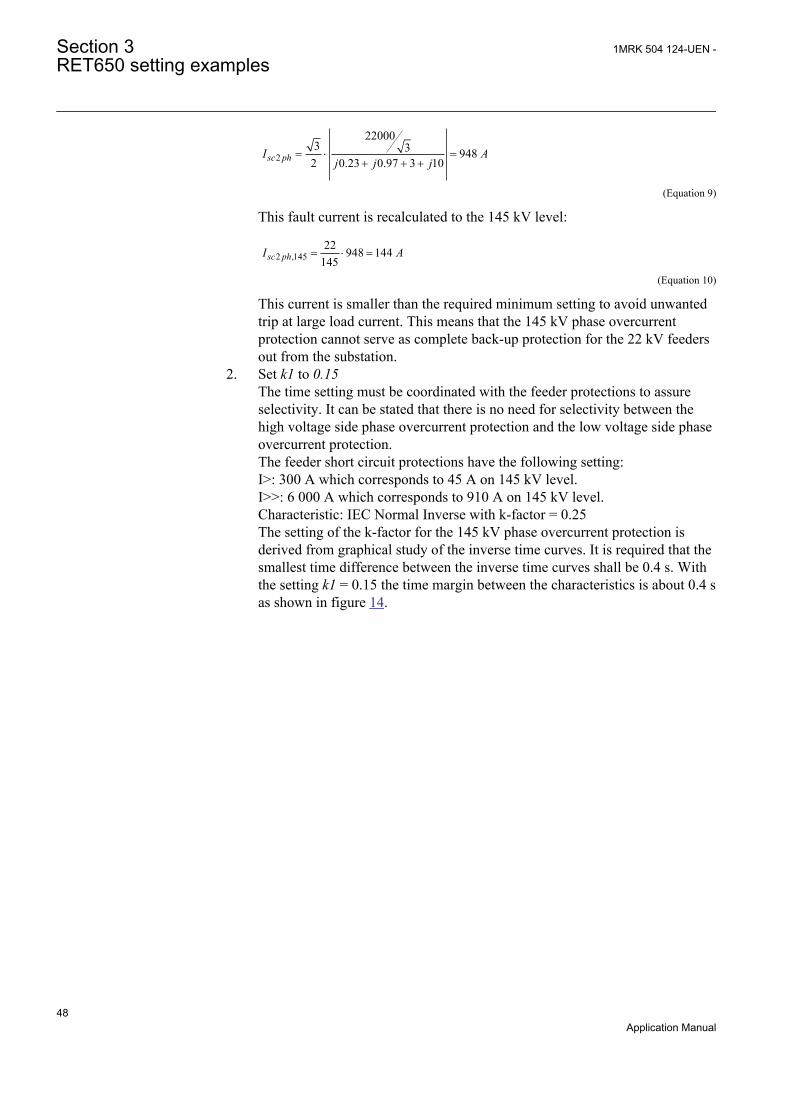
2
220003 3 948
2 0.23 0.97 3 10sc phI Aj j j
= × =+ + +
GUID-2C4DC073-E49B-45BB-8136-96B455CC57A1 V1 EN (Equation 9)
This fault current is recalculated to the 145 kV level:
2 ,14522 948 144
145sc phI A= × =
GUID-2E36019B-9370-4703-9B31-91870BBD7BDB V1 EN (Equation 10)
This current is smaller than the required minimum setting to avoid unwantedtrip at large load current. This means that the 145 kV phase overcurrentprotection cannot serve as complete back-up protection for the 22 kV feedersout from the substation.
2. Set k1 to 0.15The time setting must be coordinated with the feeder protections to assureselectivity. It can be stated that there is no need for selectivity between thehigh voltage side phase overcurrent protection and the low voltage side phaseovercurrent protection.The feeder short circuit protections have the following setting:I>: 300 A which corresponds to 45 A on 145 kV level.I>>: 6 000 A which corresponds to 910 A on 145 kV level.Characteristic: IEC Normal Inverse with k-factor = 0.25The setting of the k-factor for the 145 kV phase overcurrent protection isderived from graphical study of the inverse time curves. It is required that thesmallest time difference between the inverse time curves shall be 0.4 s. Withthe setting k1 = 0.15 the time margin between the characteristics is about 0.4 sas shown in figure 14.
Section 3 1MRK 504 124-UEN -RET650 setting examples
48Application Manual
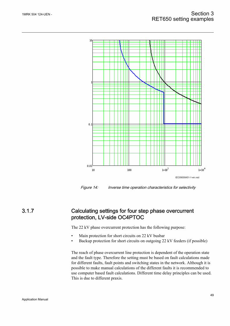
IEC09000451 V1 EN
Figure 14: Inverse time operation characteristics for selectivity
3.1.7 Calculating settings for four step phase overcurrentprotection, LV-side OC4PTOCThe 22 kV phase overcurrent protection has the following purpose:
• Main protection for short circuits on 22 kV busbar• Backup protection for short circuits on outgoing 22 kV feeders (if possible)
The reach of phase overcurrent line protection is dependent of the operation stateand the fault type. Therefore the setting must be based on fault calculations madefor different faults, fault points and switching states in the network. Although it ispossible to make manual calculations of the different faults it is recommended touse computer based fault calculations. Different time delay principles can be used.This is due to different praxis.
1MRK 504 124-UEN - Section 3RET650 setting examples
49Application Manual
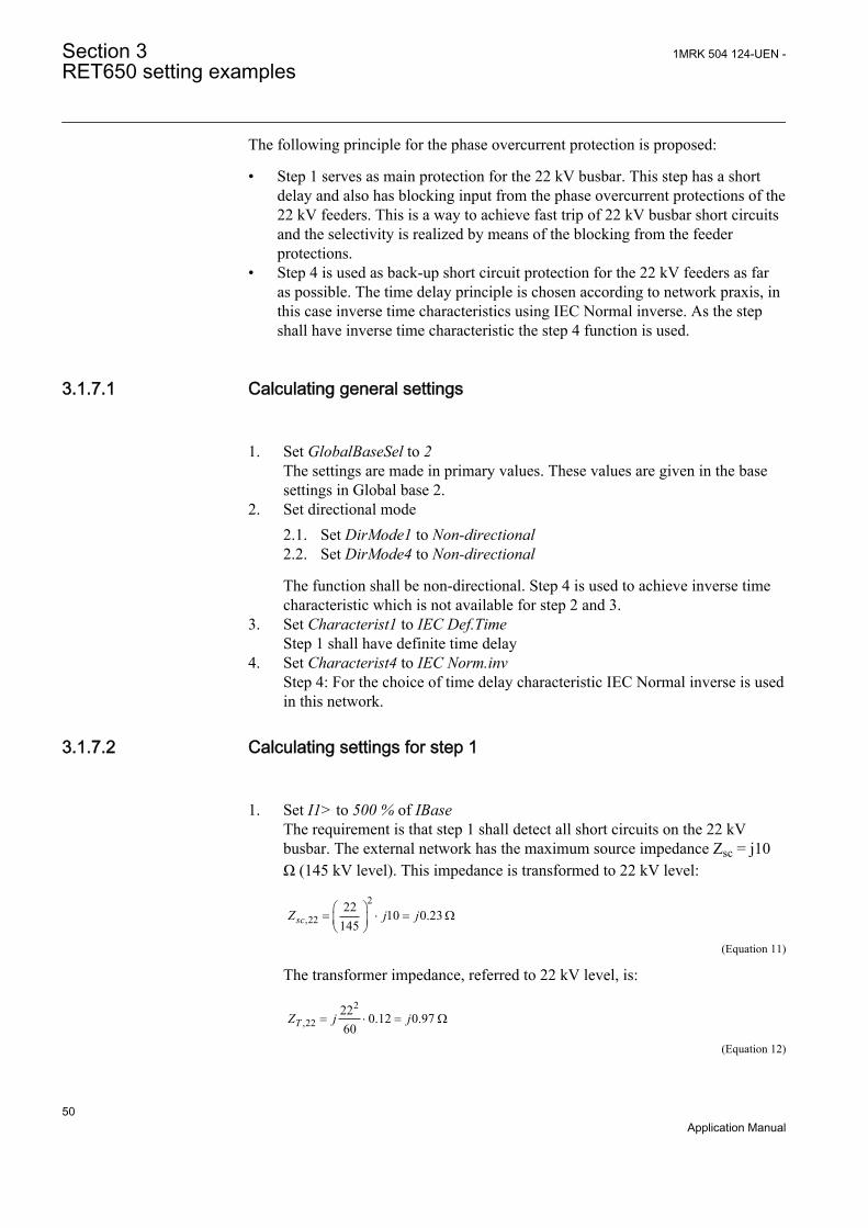
The following principle for the phase overcurrent protection is proposed:
• Step 1 serves as main protection for the 22 kV busbar. This step has a shortdelay and also has blocking input from the phase overcurrent protections of the22 kV feeders. This is a way to achieve fast trip of 22 kV busbar short circuitsand the selectivity is realized by means of the blocking from the feederprotections.
• Step 4 is used as back-up short circuit protection for the 22 kV feeders as faras possible. The time delay principle is chosen according to network praxis, inthis case inverse time characteristics using IEC Normal inverse. As the stepshall have inverse time characteristic the step 4 function is used.
3.1.7.1 Calculating general settings
1. Set GlobalBaseSel to 2The settings are made in primary values. These values are given in the basesettings in Global base 2.
2. Set directional mode2.1. Set DirMode1 to Non-directional2.2. Set DirMode4 to Non-directional
The function shall be non-directional. Step 4 is used to achieve inverse timecharacteristic which is not available for step 2 and 3.
3. Set Characterist1 to IEC Def.TimeStep 1 shall have definite time delay
4. Set Characterist4 to IEC Norm.invStep 4: For the choice of time delay characteristic IEC Normal inverse is usedin this network.
3.1.7.2 Calculating settings for step 1
1. Set I1> to 500 % of IBaseThe requirement is that step 1 shall detect all short circuits on the 22 kVbusbar. The external network has the maximum source impedance Zsc = j10Ω (145 kV level). This impedance is transformed to 22 kV level:
2
,2222 10 0.23
145scZ j jæ ö= × = Wç ÷è ø
GUID-A4805F4D-20EC-4B39-A39D-925513515FA5 V1 EN (Equation 11)
The transformer impedance, referred to 22 kV level, is:
2
,2222 0.12 0.9760TZ j j= × = W
GUID-CB0D94B6-5BFA-42EB-AE4A-B0EE898A0D78 V1 EN (Equation 12)
Section 3 1MRK 504 124-UEN -RET650 setting examples
50Application Manual

Calculation of a phase-to-phase short circuit at this busbar:
23 22000 / 3 9167
2 0.23 0.97sc phI Aj j
= × =+
GUID-846C7A33-F976-45DF-95E9-75124D6A24D2 V1 EN (Equation 13)
The setting is chosen to 5 IBase with corresponds to 7 875 A primary current.2. Set t1 to 0.1 s
The time delay must be chosen so that the blocking signal shall be able toprevent unwanted operation at feeder short circuits. 0.1 s should be sufficient.
3.1.7.3 Calculating settings for step 2
The first requirement is that the phase overcurrent protection shall never trip forload current during the extreme high load situations. It is assumed that thetransformer shall be able to be operated up to 130 % of the rated power duringlimited time. Further shall the protection resetting ratio be considered. Theresetting ratio is 0.95. The minimum setting can be calculated as follows:
1 60 10001.3 21550.95 3 22puI A×
³ × × =×
GUID-4D6B62EC-32DC-433E-B1C8-D23E8D06D017 V1 EN (Equation 14)
The next requirement is that the protection shall be able to detect all short circuitswithin the defined protected zone. In this case it is required, if possible, that theprotection shall detect phase-to-phase short circuit at the most remote point of theoutgoing feeders as shown in figure 15.
145kV
11
1
33
IEC09000452-1-en.vsd
RET650
Ph-Ph
22kV
I>
IEC09000452 V1 EN
Figure 15: Fault calculation for phase overcurrent protection
The following fault is applied: phase-phase-earth short circuit. In this calculationshould the short circuit power in the feeding substation be minimized (the sourceimpedance maximized).
1. Set I2> to 140 % of IBase2205 A primary current.
1MRK 504 124-UEN - Section 3RET650 setting examples
51Application Manual
The longest 22 kV feeder has the impedance Z = 3 + j10 Ω. The externalnetwork has the maximum source impedance Zsc = j10 Ω (145 kV level).This impedance is transformed to 22 kV level:
2
,2222 10 0.23
145scZ j jæ ö= × = Wç ÷è ø
GUID-BA67F1FC-2DCE-4E04-BBB3-FABB86FDEA3A V1 EN (Equation 15)
The transformer impedance, referred to 22 kV level, is:The phase-to-phase fault current can be calculated:
23 22000 / 3 949
2 0.23 0.97 3 10sc phI Aj j j
= × =+ + +
GUID-BAA8989B-EF8F-4277-9B2B-EBBCA35ED7C2 V1 EN (Equation 16)
This current is smaller than the required minimum setting to avoid unwantedtrip at large load current. This means that the 22 kV phase overcurrentprotection cannot serve as complete back-up protection for the 22 kV feedersout from the substation.
2. Set k4 to 0.15The feeder short circuit protections have the following setting:I>: 300 A.I>>: 6 000 A.Characteristic: IEC Normal Inverse with k-factor = 0.25The setting of the k-factor for the 22 kV phase overcurrent protection isderived from graphical study of the inverse time curves. It is required that thesmallest time difference between the inverse time curves is 0.4 s. With thesetting k4= 0.15 the time margin between the characteristics is about 0.4 s asshown in figure 16.
Section 3 1MRK 504 124-UEN -RET650 setting examples
52Application Manual
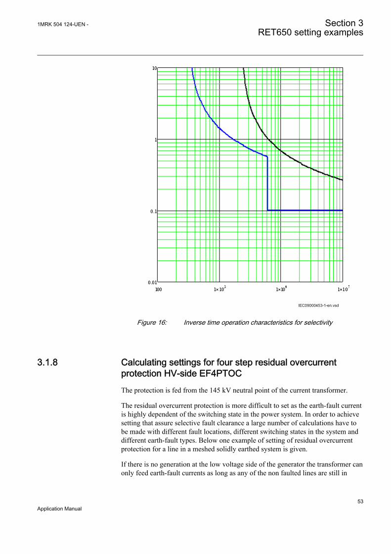
IEC09000453 V1 EN
Figure 16: Inverse time operation characteristics for selectivity
3.1.8 Calculating settings for four step residual overcurrentprotection HV-side EF4PTOCThe protection is fed from the 145 kV neutral point of the current transformer.
The residual overcurrent protection is more difficult to set as the earth-fault currentis highly dependent of the switching state in the power system. In order to achievesetting that assure selective fault clearance a large number of calculations have tobe made with different fault locations, different switching states in the system anddifferent earth-fault types. Below one example of setting of residual overcurrentprotection for a line in a meshed solidly earthed system is given.
If there is no generation at the low voltage side of the generator the transformer canonly feed earth-fault currents as long as any of the non faulted lines are still in
1MRK 504 124-UEN - Section 3RET650 setting examples
53Application Manual

operation. If there is generation connected to the low voltage side of thetransformer the transformer can feed 145 kV earth-faults alone.
The residual overcurrent protection has the following purpose:
• Fast and sensitive protection for earth-faults on the 145 kV busbar• Backup protection for earth-faults in the 145 kV transformer winding• Backup protection for earth-faults on the 145 kV lines out from the substation• Sensitive detection of high resistive earth-faults and series faults in the 145 kV
network
The reach of residual overcurrent line protection is dependent of the operation stateand the fault type. Therefore the setting must be based on fault calculations madefor different faults, fault points and switching states in the network. Although it ispossible to make hand calculations of the different faults it is recommended to usecomputer based fault calculations. Different time delay principles can be used. Thisis due to different praxis.
The following principle for the residual overcurrent protection is proposed:
• Step 1 (IN1>) with high current setting and a short delay (about 0.4 s). Step 1has non-directional function. This step gives fast trip for the busbar earth-faults and some earth-faults on the lines.
• Step 2 (IN2>) with a current setting, if possible, that enables detection of earth-faults on the 145 kV lines out from the substation. Step 2 has non-directionalfunction. The function has a delay to enable selectivity to the line protections.
• Step 3 (IN4>) with a current setting that enables detection of high resistiveearth-faults and series faults in the network. Step 3 has non-directionalfunction. The function has a longer delay to enable selectivity.
3.1.8.1 Calculating general settings
The settings are made in primary values. These values are given in the base settingsin Global base 1.
1. Set GlobalBaseSel to 12. Set DirMode1, DirMode2 and DirMode4 to Non-directional3. Set DirMode3 to Off
3.1.8.2 Calculating settings for step 1
Set operating residual current level and time delay
1. Set IN1> to 650% of IBase, corresponding to 1553 AFaults are applied at the 145 kV busbar as shown in figure 17.
Section 3 1MRK 504 124-UEN -RET650 setting examples
54Application Manual
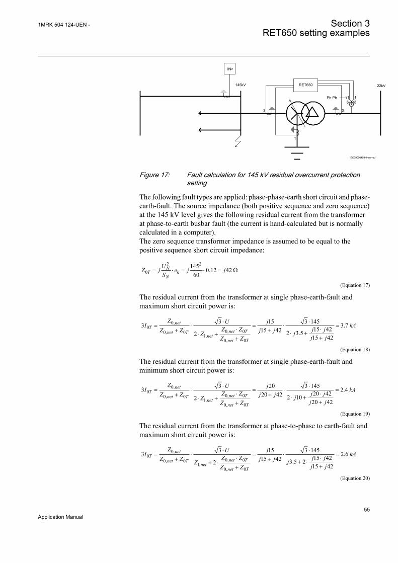
11
1
33
IEC09000454-1-en.vsd
IN>
RET650
Ph-Ph
22kV145kV
IEC09000454 V1 EN
Figure 17: Fault calculation for 145 kV residual overcurrent protectionsetting
The following fault types are applied: phase-phase-earth short circuit and phase-earth-fault. The source impedance (both positive sequence and zero sequence)at the 145 kV level gives the following residual current from the transformerat phase-to-earth busbar fault (the current is hand-calculated but is normallycalculated in a computer).The zero sequence transformer impedance is assumed to be equal to thepositive sequence short circuit impedance:
2 2
0145 0.12 42
60N
T kN
UZ j e j jS
= × = × = W
GUID-50CCC0F7-742D-45C4-84BC-923222214C69 V1 EN (Equation 17)
The residual current from the transformer at single phase-earth-fault andmaximum short circuit power is:
0,0
0, 00, 01,
0, 0
3 15 3 1453 3.715 4215 42 2 3.52 15 42
netT
net Tnet Tnet
net T
Z U jI kAZ Z j jZ Z j j jZ j jZ Z
× ×= × = × =
× ×+ + × +× +++
GUID-CC2E2412-4939-4285-A491-FCCC0AE0F939 V1 EN (Equation 18)
The residual current from the transformer at single phase-earth-fault andminimum short circuit power is:
0,0
0, 00, 01,
0, 0
3 20 3 1453 2.420 4220 42 2 102 20 42
netT
net Tnet Tnet
net T
Z U jI kAZ Z j jZ Z j j jZ j jZ Z
× ×= × = × =
× ×+ + × +× +++
GUID-991D27BC-4413-4A9B-BF49-F25986545C73 V1 EN (Equation 19)
The residual current from the transformer at phase-to-phase to earth-fault andmaximum short circuit power is:
0,0
0, 00, 01,
0, 0
3 15 3 1453 2.615 4215 42 3.5 22 15 42
netT
net Tnet Tnet
net T
Z U jI kAZ Z j jZ Z j j jZ j jZ Z
× ×= × = × =
× ×+ + + ×+ ×++
GUID-CA17A1A5-E141-4F0B-B7C0-74683F9F9AD1 V1 EN (Equation 20)
1MRK 504 124-UEN - Section 3RET650 setting examples
55Application Manual
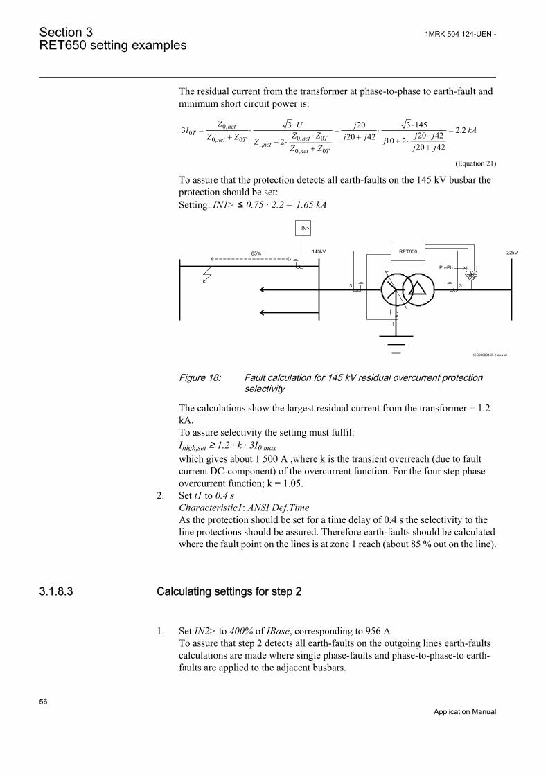
The residual current from the transformer at phase-to-phase to earth-fault andminimum short circuit power is:
0,0
0, 00, 01,
0, 0
3 20 3 1453 2.220 4220 42 10 22 20 42
netT
net Tnet Tnet
net T
Z U jI kAZ Z j jZ Z j j jZ j jZ Z
× ×= × = × =
× ×+ + + ×+ ×++
GUID-933BE756-31CD-45BA-B3EB-5DC00CA25DC0 V1 EN (Equation 21)
To assure that the protection detects all earth-faults on the 145 kV busbar theprotection should be set:Setting: IN1> ≤ 0.75 · 2.2 = 1.65 kA
11
1
33
IEC09000455-1-en.vsd
IN>
145kV RET650
Ph-Ph
22kV85%
IEC09000455 V1 EN
Figure 18: Fault calculation for 145 kV residual overcurrent protectionselectivity
The calculations show the largest residual current from the transformer = 1.2kA.To assure selectivity the setting must fulfil:Ihigh,set ≥ 1.2 · k · 3I0 maxwhich gives about 1 500 A ,where k is the transient overreach (due to faultcurrent DC-component) of the overcurrent function. For the four step phaseovercurrent function; k = 1.05.
2. Set t1 to 0.4 sCharacteristic1: ANSI Def.TimeAs the protection should be set for a time delay of 0.4 s the selectivity to theline protections should be assured. Therefore earth-faults should be calculatedwhere the fault point on the lines is at zone 1 reach (about 85 % out on the line).
3.1.8.3 Calculating settings for step 2
1. Set IN2> to 400% of IBase, corresponding to 956 ATo assure that step 2 detects all earth-faults on the outgoing lines earth-faultscalculations are made where single phase-faults and phase-to-phase-to earth-faults are applied to the adjacent busbars.
Section 3 1MRK 504 124-UEN -RET650 setting examples
56Application Manual
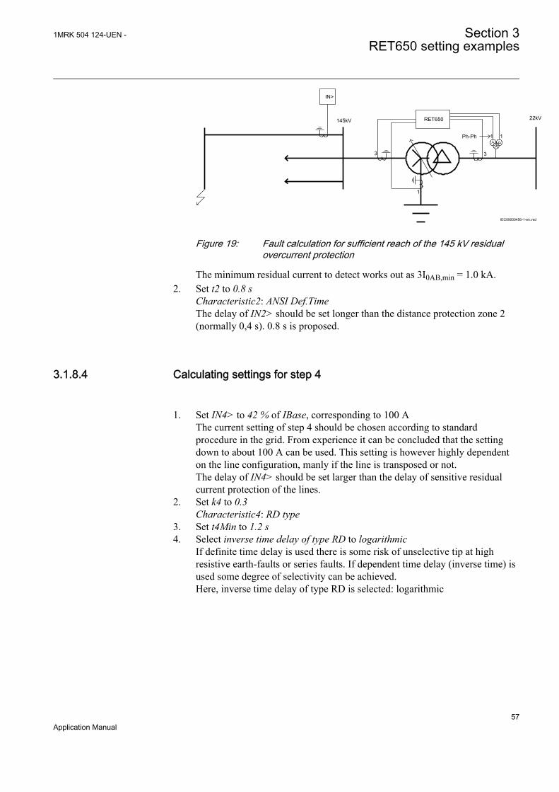
11
1
33
IEC09000456-1-en.vsd
IN>
145kV RET650 22kV
Ph-Ph
IEC09000456 V1 EN
Figure 19: Fault calculation for sufficient reach of the 145 kV residualovercurrent protection
The minimum residual current to detect works out as 3I0AB,min = 1.0 kA.2. Set t2 to 0.8 s
Characteristic2: ANSI Def.TimeThe delay of IN2> should be set longer than the distance protection zone 2(normally 0,4 s). 0.8 s is proposed.
3.1.8.4 Calculating settings for step 4
1. Set IN4> to 42 % of IBase, corresponding to 100 AThe current setting of step 4 should be chosen according to standardprocedure in the grid. From experience it can be concluded that the settingdown to about 100 A can be used. This setting is however highly dependenton the line configuration, manly if the line is transposed or not.The delay of IN4> should be set larger than the delay of sensitive residualcurrent protection of the lines.
2. Set k4 to 0.3Characteristic4: RD type
3. Set t4Min to 1.2 s4. Select inverse time delay of type RD to logarithmic
If definite time delay is used there is some risk of unselective tip at highresistive earth-faults or series faults. If dependent time delay (inverse time) isused some degree of selectivity can be achieved.Here, inverse time delay of type RD is selected: logarithmic
1MRK 504 124-UEN - Section 3RET650 setting examples
57Application Manual

3.1.9 Calculating settings for two step residual overvoltageprotection LV-side, ROV2PTOVThe residual overvoltage protection is fed from the open delta connected voltagetransformer at the 22 kV side of the transformer.
The residual overvoltage protection has the following purpose:
• Back-up protection for earth-faults on the 22 kV feeders out from the substation.• Main protection for earth-faults on the 22 kV busbar• Main protection for earth-faults on the 22 kV transformer winding
The residual voltage protection has two steps. In this application step 1 should tripthe 22 kV circuit breaker and if the earth-fault is situated in the transformer 22 kVwinding or between the transformer and the 22 kV breaker the 145 kV breaker istripped from step 2.
The voltage setting of the protection is depending on the required sensitivity andthe system earthing. The 22 kV system has earthing with a Petersen coil (connectedto the system via a separate earthing transformer) and a parallel neutral pointresistor. The Petersen coil is tuned to compensate for the capacitive earth-faultcurrent in the 22 kV system. The neutral point resistor gives 10 A earth-faultcurrent at zero resistance earth-fault. This means that the resistance is
22000 3 127010N
/R W= =
GUID-4ECDF824-B17E-436D-A668-ACA06BB375F7 V2 EN (Equation 22)
The total zero sequence impedance of the 22 kV system is
Z0 = 3RN // j3XN // — jXC Ω / phase
As the Petersen coil is tuned the zero sequence impedance is:
Z0 = 3RN Ω / phase
The Residual voltage at resistive earth-fault in the 22 kV system is:
0
0 0
13 3
1 1
Phaseo
f fphase
U UU orR RUZ Z
= =× ×
+ +
GUID-AD49C138-F37B-4690-9E37-BA2BAD678A17 V1 EN (Equation 23)
In our case the requirement is that earth-faults with resistance up to 5 000 Ω shallbe detected. This gives:
0 1 0 203 500013 1270
phase
U .U
= =×
+×
GUID-42D376ED-052F-4E9B-B4D9-8D679127BC0C V1 EN (Equation 24)
Section 3 1MRK 504 124-UEN -RET650 setting examples
58Application Manual

Step 1 and step 2 is given the same voltage setting but step 2 shall have longer timedelay.
The residual earth-fault protection shall have definite time delay. The time settingis set longer than the time delay of the earth-fault protection of the outgoing feedershaving maximum 2 s delay. Time delay for step 1 is set to 3 s and the time delayfor step 2 is set to 4 s.
1. Set GlobalBaseSel to 2The settings are made in primary values. These values are given in the basesettings in Global base 2.
2. Set Characteristic1 to Definite time3. Set U1> to 20 % of UBase4. Set t1 to 3.0 s5. Set U2> to 20 % of UBase6. Set t2 to 4.0 s
3.1.10 Calculating settings for breaker failure protection HV-side,CCRBRFThe breaker failure protection can use either contact function in the circuit breakeror current measurement to detect correct breaker function. For line protections itseems to be most suitable function is to use current measurement breaker check.
1. Set GlobalBaseSel to 1The settings are made in primary values. These values are given in the basesettings in Global base 1.
2. Set FunctionMode to Current3. Set BuTripMode to 1 out of 4
In the current measurement the three-phase currents out on the line is used. Itis also possible to measure the residual current (analogue input 4). The logicsto detect failure of the circuit breaker can be chosen:• 1 out of 3: at least one of the three-phase current shall be larger than the
set level to detect failure to break• 1 out of 4: at least one of the three-phase current and the residual current
shall be larger than the set level to detect failure to break• 2 out of 4: at least two of the three-phase current and the residual
current shall be larger than the set level to detect failure to break As theresidual current protection is one of the protection functions to initiatethe breaker failure protection the setting 1 out of 4 is chosen.
4. Set IP> to 20 % of IBaseIP> should be set lower than the smallest current to be detected by thedifferential protection which is set 25 % of IBase.
5. Set IN> to 20 % of IBase
1MRK 504 124-UEN - Section 3RET650 setting examples
59Application Manual
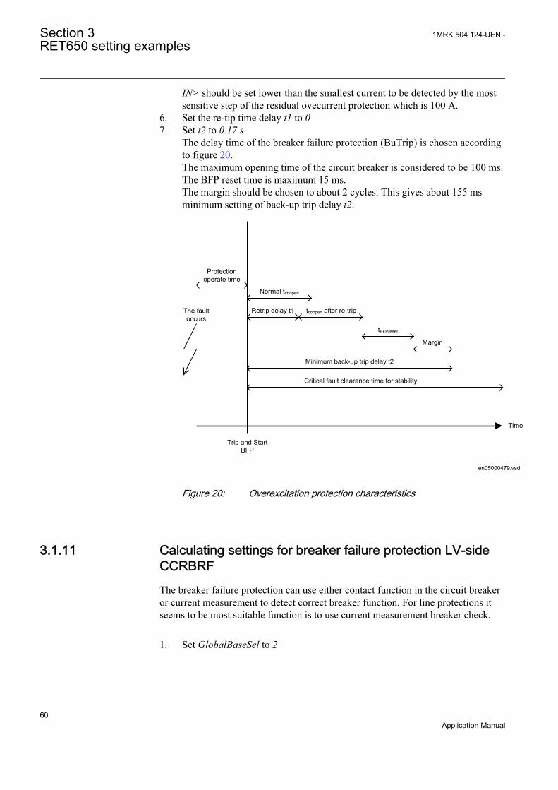
IN> should be set lower than the smallest current to be detected by the mostsensitive step of the residual ovecurrent protection which is 100 A.
6. Set the re-tip time delay t1 to 07. Set t2 to 0.17 s
The delay time of the breaker failure protection (BuTrip) is chosen accordingto figure 20.The maximum opening time of the circuit breaker is considered to be 100 ms.The BFP reset time is maximum 15 ms.The margin should be chosen to about 2 cycles. This gives about 155 msminimum setting of back-up trip delay t2.
Time
The fault occurs
Protection operate time
Trip and Start BFP
Normal tcbopen
Margin
Retrip delay t1 tcbopen after re-trip
tBFPreset
Minimum back-up trip delay t2
Critical fault clearance time for stability
en05000479.vsdEN05000479 V1 EN
Figure 20: Overexcitation protection characteristics
3.1.11 Calculating settings for breaker failure protection LV-sideCCRBRFThe breaker failure protection can use either contact function in the circuit breakeror current measurement to detect correct breaker function. For line protections itseems to be most suitable function is to use current measurement breaker check.
1. Set GlobalBaseSel to 2
Section 3 1MRK 504 124-UEN -RET650 setting examples
60Application Manual

The settings are made in primary values. These values are given in the basesettings in Global base 2.
2. Set FunctionMode to Current3. Set BuTripMode to 1 out of 3
In the current measurement the three-phase currents out on the line is used. Itis also possible to measure the residual current (analogue input 4). The logicsto detect failure of the circuit breaker can be chosen:• 1 out of 3: at least one of the three-phase current shall be larger than the
set level to detect failure to break• 1 out of 4: at least one of the three-phase current and the residual current
shall be larger than the set level to detect failure to break• 2 out of 4: at least two of the three-phase current and the residual
current shall be larger than the set level to detect failure to break.
There is no residual current measurement protection on the 22 kV side of thetransformer. Therefore 1 out of 3 is chosen.
4. Set IP> to 20 % of IBaseIP> should be set lower than the smallest current to be detected by thedifferential protection which is set 25 % of IBase.
5. Set the re-tip time delay t1 to 0 s6. Set t2 to 0.17 s
The delay time of the breaker failure protection (BuTrip) is chosen accordingto figure 20.The maximum open time of the circuit breaker is considered to be 100 ms.The breaker failure protection reset time is maximum 15 ms.The margin should be chosen to about 2 cycles.This gives about 155 ms minimum setting of back-up trip delay t2.
1MRK 504 124-UEN - Section 3RET650 setting examples
61Application Manual

Time
The fault occurs
Protection operate time
Trip and Start BFP
Normal tcbopen
Margin
Retrip delay t1 tcbopen after re-trip
tBFPreset
Minimum back-up trip delay t2
Critical fault clearance time for stability
en05000479.vsdEN05000479 V1 EN
Figure 21: Time sequences for breaker failure protection setting
Section 3 1MRK 504 124-UEN -RET650 setting examples
62Application Manual

Section 4 Analog inputs
4.1 Introduction
Analog input channels are already configured inside the IED. However the IED hasto be set properly to get correct measurement results and correct protectionoperations. For power measuring and all directional and differential functions thedirections of the input currents must be defined properly. Measuring and protectionalgorithms in the IED use primary system quantities. Set values are done inprimary quantities as well and it is important to set the data about the connectedcurrent and voltage transformers properly.
The availability of CT and VT inputs, as well as setting parameters depends on theordered IED.
A reference PhaseAngleRefmust be defined to facilitate service values reading.This analog channels phase angle will always be fixed to zero degree and all otherangle information will be shown in relation to this analog input. During testing andcommissioning of the IED the reference channel can be changed to facilitate testingand service values reading.
4.2 Setting guidelines
4.2.1 Setting of the phase reference channelAll phase angles are calculated in relation to a defined reference. An appropriateanalog input channel is selected and used as phase reference. The parameterPhaseAngleRef defines the analog channel that is used as phase angle reference.
4.2.1.1 Example
The setting shall be used if a phase-to-earth voltage (usually the L1 phase-to-earthvoltage connected to VT channel number 10 of the analog card) is selected to bethe phase reference.
4.2.1.2 Setting of current channels
The direction of a current to the IED is depending on the connection of the CT.Unless indicated otherwise, the main CTs are supposed to be star connected andcan be connected with the earthing point to the object or from the object. This
1MRK 504 124-UEN - Section 4Analog inputs
63Application Manual

information must be set to the IED. The convention of the directionality is definedas follows: A positive value of current, power, and so on means that the quantityhas the direction into the object and a negative value means direction out from theobject. For directional functions the direction into the object is defined as Forwardand the direction out from the object is defined as Reverse. See figure 22
Protected ObjectLine, transformer, etc
ForwardReverse
Definition of directionfor directional functions
Measured quantity ispositive when flowing
towards the object
e.g. P, Q, I
ReverseForward
Definition of directionfor directional functions
e.g. P, Q, IMeasured quantity ispositive when flowing
towards the object
Set parameterCTStarPoint
Correct Setting is"ToObject"
Set parameterCTStarPoint
Correct Setting is"FromObject"
en05000456.vsdIEC05000456 V1 EN
Figure 22: Internal convention of the directionality in the IED
With correct setting of the primary CT direction, CTStarPoint set to FromObject orToObject, a positive quantities always flowing towards the object and a directiondefined as Forward always is looking towards the object. The following examplesshow the principle.
4.2.1.3 Example 1
Two IEDs used for protection of two objects.
Section 4 1MRK 504 124-UEN -Analog inputs
64Application Manual
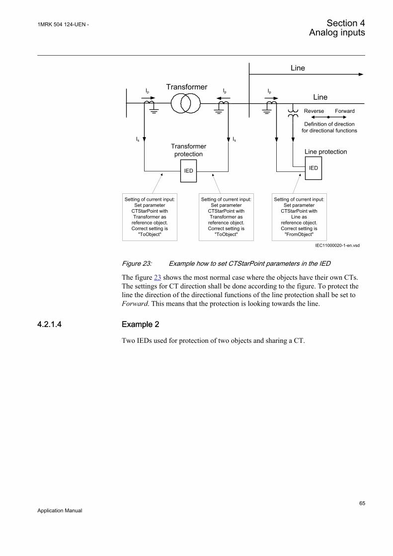
Transformer protection
TransformerLine
Line
Setting of current input:Set parameter
CTStarPoint with Transformer as
reference object.Correct setting is
"ToObject"
ForwardReverse
Definition of direction for directional functions
Line protection
Setting of current input:Set parameter
CTStarPoint with Transformer as
reference object.Correct setting is
"ToObject"
Setting of current input:Set parameter
CTStarPoint withLine as
reference object.Correct setting is
"FromObject"
IEC11000020-1-en.vsd
IsIs
Ip Ip Ip
IED IED
IEC11000020 V1 EN
Figure 23: Example how to set CTStarPoint parameters in the IED
The figure 23 shows the most normal case where the objects have their own CTs.The settings for CT direction shall be done according to the figure. To protect theline the direction of the directional functions of the line protection shall be set toForward. This means that the protection is looking towards the line.
4.2.1.4 Example 2
Two IEDs used for protection of two objects and sharing a CT.
1MRK 504 124-UEN - Section 4Analog inputs
65Application Manual
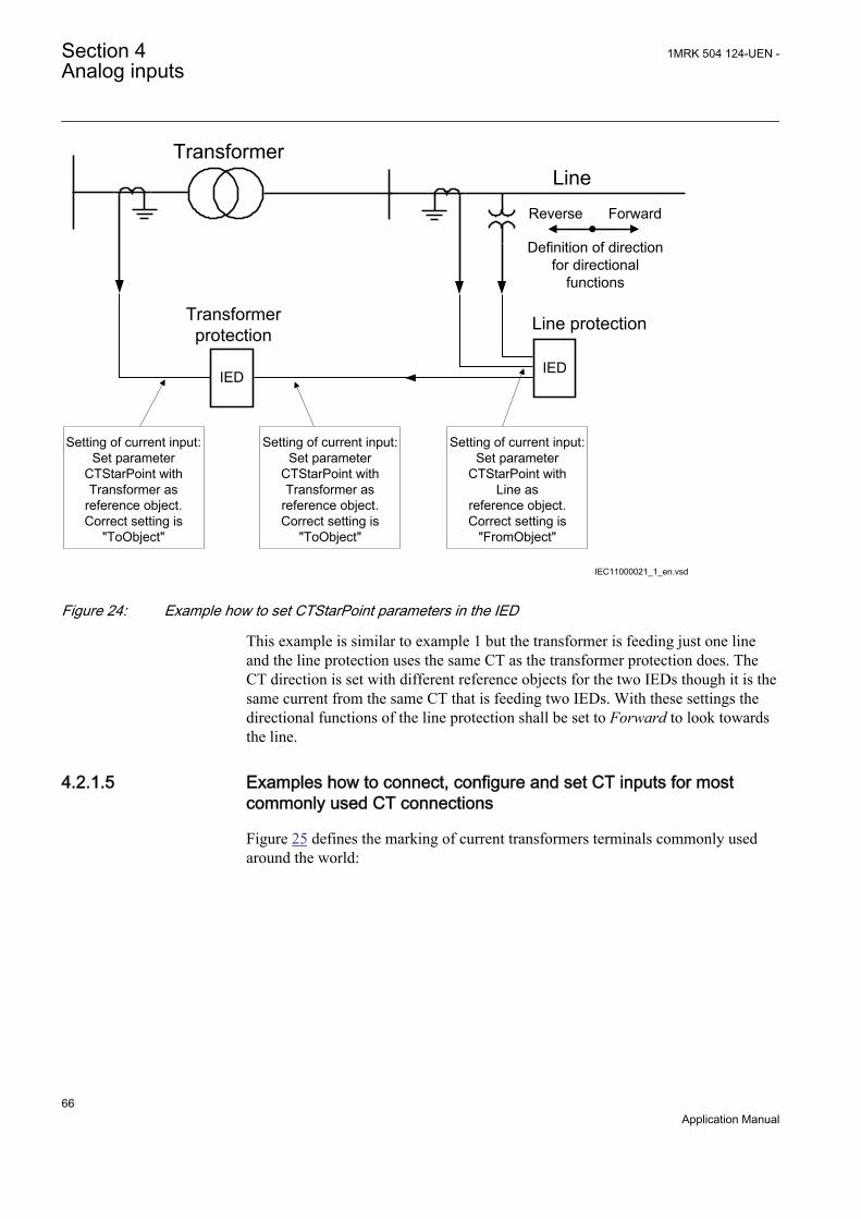
Transformer protection
TransformerLine
Setting of current input:Set parameter
CTStarPoint with Transformer as
reference object.Correct setting is
"ToObject"
ForwardReverse
Definition of direction for directional
functions
Line protection
Setting of current input:Set parameter
CTStarPoint with Transformer as
reference object.Correct setting is
"ToObject"
Setting of current input:Set parameter
CTStarPoint withLine as
reference object.Correct setting is
"FromObject"
IED IED
IEC11000021_1_en.vsdIEC11000021 V1 EN
Figure 24: Example how to set CTStarPoint parameters in the IED
This example is similar to example 1 but the transformer is feeding just one lineand the line protection uses the same CT as the transformer protection does. TheCT direction is set with different reference objects for the two IEDs though it is thesame current from the same CT that is feeding two IEDs. With these settings thedirectional functions of the line protection shall be set to Forward to look towardsthe line.
4.2.1.5 Examples how to connect, configure and set CT inputs for mostcommonly used CT connections
Figure 25 defines the marking of current transformers terminals commonly usedaround the world:
Section 4 1MRK 504 124-UEN -Analog inputs
66Application Manual
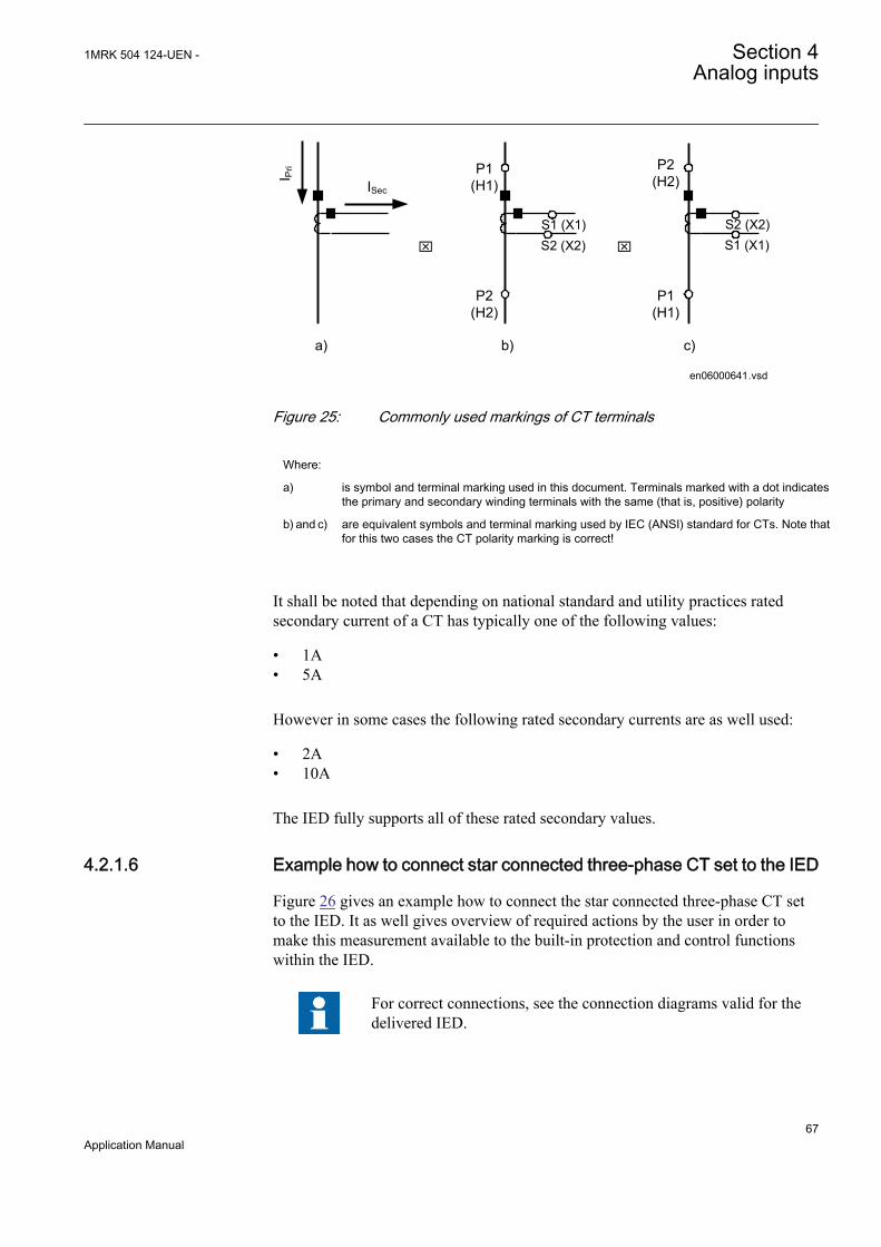
ISec
I Pri
S1 (X1)
P1(H1)
P2(H2)
S2 (X2)
P2(H2)
P1(H1)
x x
a) b) c)
en06000641.vsd
S2 (X2) S1 (X1)
IEC06000641 V1 EN
Figure 25: Commonly used markings of CT terminals
Where:
a) is symbol and terminal marking used in this document. Terminals marked with a dot indicatesthe primary and secondary winding terminals with the same (that is, positive) polarity
b) and c) are equivalent symbols and terminal marking used by IEC (ANSI) standard for CTs. Note thatfor this two cases the CT polarity marking is correct!
It shall be noted that depending on national standard and utility practices ratedsecondary current of a CT has typically one of the following values:
• 1A• 5A
However in some cases the following rated secondary currents are as well used:
• 2A• 10A
The IED fully supports all of these rated secondary values.
4.2.1.6 Example how to connect star connected three-phase CT set to the IED
Figure 26 gives an example how to connect the star connected three-phase CT setto the IED. It as well gives overview of required actions by the user in order tomake this measurement available to the built-in protection and control functionswithin the IED.
For correct connections, see the connection diagrams valid for thedelivered IED.
1MRK 504 124-UEN - Section 4Analog inputs
67Application Manual

L1IL
1
IL2
IL3
L2 L3
Protected Object
CT 600/5Star Connected
IL1
IL2
IL3
IED
IEC11000025-1-en.vsd
12
3
4
SMAI_20
IEC11000025 V1 EN
Figure 26: Star connected three-phase CT set with star point towards the protected object
Where:
1) shows how to connect three individual phase currents from star connected three-phase CTset to three CT inputs in the IED.
2) is TRM or AIM where these current inputs are located. It shall be noted that for all thesecurrent inputs the following setting values shall be entered.
• CTprim=600A• CTsec=5A• CTStarPoint=ToObject
Inside the IED only the ratio of the first two parameters is used. The third parameter as setin this example will have no influence on the measured currents (that is, currents arealready measured towards the protected object).
3) are three connections, which connects these three current inputs to three input channelsof the preprocessing function block 6). Depending on the type of functions, which need thiscurrent information, more than one preprocessing block might be connected in parallel tothese three CT inputs.
4) Preprocessing block has a task to digitally filter the connected analog inputs and calculate:
• fundamental frequency phasors for all four input channels• harmonic content for all four input channels• positive, negative and zero sequence quantities by using the fundamental frequency
phasors for the first three input channels (channel one taken as reference forsequence quantities)
These calculated values are then available for all built-in protection and control functionswithin the IED, which are connected to this preprocessing function block. For thisapplication most of the preprocessing settings can be left to the default values.If frequency tracking and compensation is required (this feature is typically required onlyfor IEDs installed in the generating stations) then the setting parameters DFTReferenceshall be set accordingly.
Section 4 1MRK 504 124-UEN -Analog inputs
68Application Manual
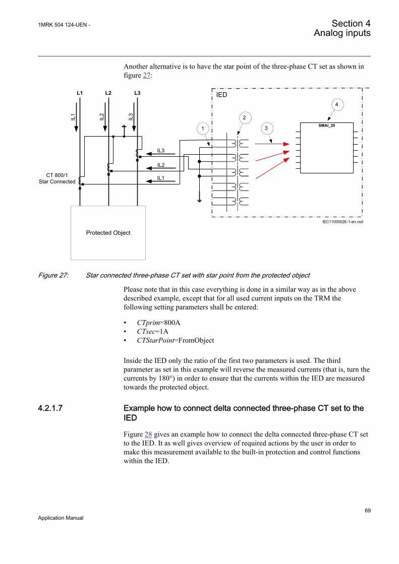
Another alternative is to have the star point of the three-phase CT set as shown infigure 27:
L1
IL1
IL2
IL3
L2 L3
Protected Object
CT 800/1Star Connected IL1
IL2
IL3
IED
IEC11000026-1-en.vsd
4
1
2
3 SMAI_20
IEC11000026 V1 EN
Figure 27: Star connected three-phase CT set with star point from the protected object
Please note that in this case everything is done in a similar way as in the abovedescribed example, except that for all used current inputs on the TRM thefollowing setting parameters shall be entered:
• CTprim=800A• CTsec=1A• CTStarPoint=FromObject
Inside the IED only the ratio of the first two parameters is used. The thirdparameter as set in this example will reverse the measured currents (that is, turn thecurrents by 180°) in order to ensure that the currents within the IED are measuredtowards the protected object.
4.2.1.7 Example how to connect delta connected three-phase CT set to theIED
Figure 28 gives an example how to connect the delta connected three-phase CT setto the IED. It as well gives overview of required actions by the user in order tomake this measurement available to the built-in protection and control functionswithin the IED.
1MRK 504 124-UEN - Section 4Analog inputs
69Application Manual
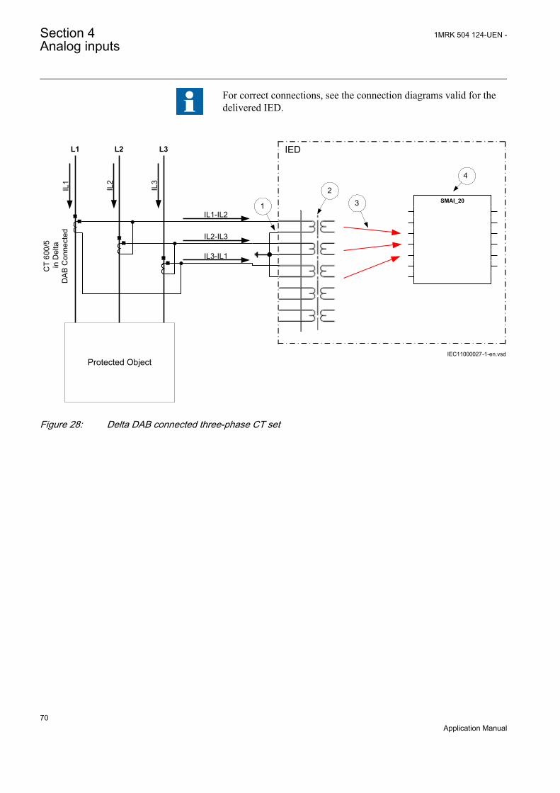
For correct connections, see the connection diagrams valid for thedelivered IED.
L1
IL1
IL2
IL3
L2 L3
Protected Object
IED
CT
600/
5 in
Del
taD
AB C
onne
cted
IL1-IL2
IL2-IL3
IL3-IL1
1
2 3
4
IEC11000027-1-en.vsd
SMAI_20
IEC11000027 V1 EN
Figure 28: Delta DAB connected three-phase CT set
Section 4 1MRK 504 124-UEN -Analog inputs
70Application Manual

Where:
1) shows how to connect three individual phase currents from delta connected three-phaseCT set to three CT inputs in the IED.
2) is TRM or AIM where these current inputs are located. It shall be noted that for all thesecurrent inputs the following setting values shall be entered.
• CTprim=600/1.732=346A• CTsec=5A• CTStarPoint=ToObject
Inside the IED only the ratio of the first two parameters is used. The third parameter as setin this example will have no influence on the measured currents (that is, currents arealready measured towards the protected object).
3) are three connections, which connect these three current inputs to three input channels ofthe preprocessing function block 6). Depending on type of functions which need thiscurrent information, more then one preprocessing block might be connected in parallel tothese three CT inputs.
4) Preprocessing block has a task to digitally filter the connected analog inputs and calculate:
• fundamental frequency phasors for all four input channels• harmonic content for all four input channels• positive, negative and zero sequence quantities by using the fundamental frequency
phasors for the first three input channels (channel one taken as reference forsequence quantities)
These calculated values are then available for all built-in protection and control functionswithin the IED, which are connected to this preprocessing function block. For thisapplication most of the preprocessing settings can be left to the default values.If frequency tracking and compensation is required (this feature is typically required onlyfor IEDs installed in the generating stations) then the setting parameters DFTReferenceshall be set accordingly.
Another alternative is to have the delta connected CT set as shown in figure 29:
1MRK 504 124-UEN - Section 4Analog inputs
71Application Manual
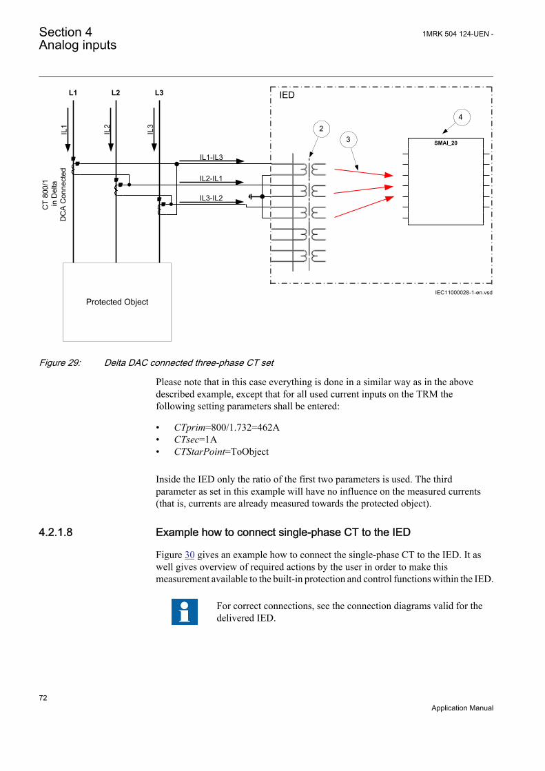
L1
IL1
IL2
IL3
L2 L3
Protected Object
IED
CT
800/
1 in
Del
taD
CA
Con
nect
ed
IL3-IL2
IL2-IL1
IL1-IL3
2 3
4
IEC11000028-1-en.vsd
SMAI_20
IEC11000028 V1 EN
Figure 29: Delta DAC connected three-phase CT set
Please note that in this case everything is done in a similar way as in the abovedescribed example, except that for all used current inputs on the TRM thefollowing setting parameters shall be entered:
• CTprim=800/1.732=462A• CTsec=1A• CTStarPoint=ToObject
Inside the IED only the ratio of the first two parameters is used. The thirdparameter as set in this example will have no influence on the measured currents(that is, currents are already measured towards the protected object).
4.2.1.8 Example how to connect single-phase CT to the IED
Figure 30 gives an example how to connect the single-phase CT to the IED. It aswell gives overview of required actions by the user in order to make thismeasurement available to the built-in protection and control functions within the IED.
For correct connections, see the connection diagrams valid for thedelivered IED.
Section 4 1MRK 504 124-UEN -Analog inputs
72Application Manual

Protected Object
L1 L2 L3
IED IN
P
INP
INP
2
IEC11000029-1-en.vsd
4
SMAI_20
3
CT
1000
/1
a)
b)
(+)
(+)
(-)
(-)(+)
(-)
1
IEC11000029 V1 EN
Figure 30: Connections for single-phase CT input
1MRK 504 124-UEN - Section 4Analog inputs
73Application Manual
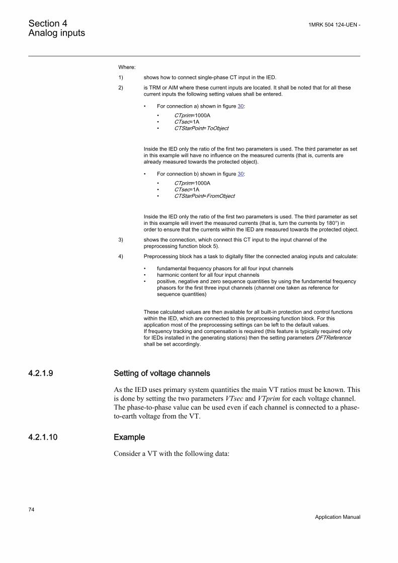
Where:
1) shows how to connect single-phase CT input in the IED.
2) is TRM or AIM where these current inputs are located. It shall be noted that for all thesecurrent inputs the following setting values shall be entered.
• For connection a) shown in figure 30:• CTprim=1000A• CTsec=1A• CTStarPoint=ToObject
Inside the IED only the ratio of the first two parameters is used. The third parameter as setin this example will have no influence on the measured currents (that is, currents arealready measured towards the protected object).
• For connection b) shown in figure 30:• CTprim=1000A• CTsec=1A• CTStarPoint=FromObject
Inside the IED only the ratio of the first two parameters is used. The third parameter as setin this example will invert the measured currents (that is, turn the currents by 180°) inorder to ensure that the currents within the IED are measured towards the protected object.
3) shows the connection, which connect this CT input to the input channel of thepreprocessing function block 5).
4) Preprocessing block has a task to digitally filter the connected analog inputs and calculate:
• fundamental frequency phasors for all four input channels• harmonic content for all four input channels• positive, negative and zero sequence quantities by using the fundamental frequency
phasors for the first three input channels (channel one taken as reference forsequence quantities)
These calculated values are then available for all built-in protection and control functionswithin the IED, which are connected to this preprocessing function block. For thisapplication most of the preprocessing settings can be left to the default values.If frequency tracking and compensation is required (this feature is typically required onlyfor IEDs installed in the generating stations) then the setting parameters DFTReferenceshall be set accordingly.
4.2.1.9 Setting of voltage channels
As the IED uses primary system quantities the main VT ratios must be known. Thisis done by setting the two parameters VTsec and VTprim for each voltage channel.The phase-to-phase value can be used even if each channel is connected to a phase-to-earth voltage from the VT.
4.2.1.10 Example
Consider a VT with the following data:
Section 4 1MRK 504 124-UEN -Analog inputs
74Application Manual

132 1103 3kV V
EQUATION2016 V1 EN (Equation 25)
The following setting should be used: VTprim=132 (value in kV) VTsec=110(value in V)
4.2.1.11 Examples how to connect, configure and set VT inputs for mostcommonly used VT connections
Figure 31 defines the marking of voltage transformers terminals commonly usedaround the world.
A(H1)
B(H2)
b(X2)
a(X1)
A(H1)
N(H2)
n(X2)
a(X1)
b) c)
A(H1)
N(H2)
dn(X2)
da(X1)
d)
UPri
+ +USec
a)
en06000591.vsdIEC06000591 V1 EN
Figure 31: Commonly used markings of VT terminals
Where:
a) is symbol and terminal marking used in this document. Terminals marked with a dotindicates the primary and secondary winding terminals with the same (that is, positive)polarity
b) is equivalent symbol and terminal marking used by IEC (ANSI) standard for phase-to-earthconnected VT
c) is equivalent symbol and terminal marking used by IEC (ANSI) standard for open deltaconnected VT
d) is equivalent symbol and terminal marking used by IEC (ANSI) standard for phase-to-phase connected VT
It shall be noted that depending on national standard and utility practices ratedsecondary voltage of a VT has typically one of the following values:
• 100 V• 110 V• 115 V• 120 V
The IED fully supports all of these values and most of them will be shown in thefollowing examples.
1MRK 504 124-UEN - Section 4Analog inputs
75Application Manual

4.2.1.12 Examples how to connect three phase-to-earth connected VTs to theIED
Figure 32 gives an example how to connect the three phase-to-earth connected VTsto the IED. It as well gives overview of required actions by the user in order tomake this measurement available to the built-in protection and control functionswithin the IED.
For correct connections, see the connection diagrams valid for thedelivered IED.
L1
IEDL2
L3
663
1103
kV
V
4
1
3
2
663
1103
kV
V
663
1103
kV
V
IEC11000031-1-en.vsd
SMAI_20
IEC11000031 V1 EN
Figure 32: Three phase-to-earth connected VTs
Section 4 1MRK 504 124-UEN -Analog inputs
76Application Manual

Where:
1) shows how to connect three secondary phase-to-earth voltages to three VT inputs in the IED
2) is TRM or AIM where these three voltage inputs are located. It shall be noted that for thesethree voltage inputs the following setting values shall be entered:VTprim=66 kVVTsec= 110 VInside the IED, only the ratio of these two parameters is used. It shall be noted that the ratioof the entered values exactly corresponds to ratio of one individual VT.
6666 3
1101103
=
EQUATION1903 V1 EN (Equation 26)
3) are three connections, which connect these three voltage inputs to three input channels ofthe preprocessing function block 5). Depending on type of functions which need this voltageinformation, more then one preprocessing block might be connected in parallel to thesethree VT inputs
4) Preprocessing block has a task to digitally filter the connected analog inputs and calculate:
• fundamental frequency phasors for all four input channels• harmonic content for all four input channels• positive, negative and zero sequence quantities by using the fundamental frequency
phasors for the first three input channels (channel one taken as reference forsequence quantities)
These calculated values are then available for all built-in protection and control functionswithin the IED, which are connected to this preprocessing function block. For thisapplication most of the preprocessing settings can be left to the default values. However thefollowing settings shall be set as shown here:UBase=66 kV (that is, rated Ph-Ph voltage)If frequency tracking and compensation is required (this feature is typically required only forIEDs installed in the generating stations) then the setting parameters DFTReference shallbe set accordingly.
4.2.1.13 Example how to connect two phase-to-phase connected VTs to the IED
Figure 33 gives an example how to connect the two phase-to-phase connected VTsto the IED. It as well gives overview of required actions by the user in order tomake this measurement available to the built-in protection and control functionswithin the IED. It shall be noted that this VT connection is only used on lowervoltage levels (that is, rated primary voltage below 40 kV).
For correct connections, see the connection diagrams valid for thedelivered IED.
1MRK 504 124-UEN - Section 4Analog inputs
77Application Manual
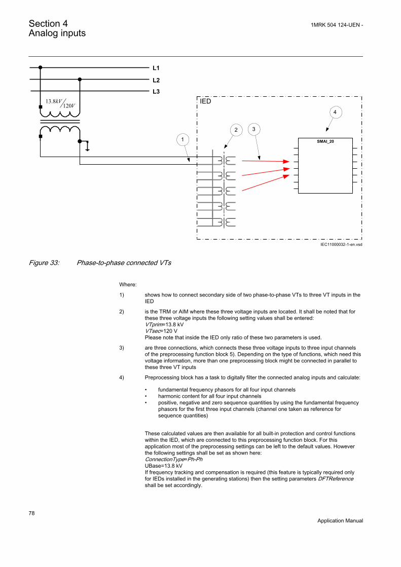
L1
IED
L2
L3
1
2 3
4
13.8120
kVV
IEC11000032-1-en.vsd
SMAI_20
IEC11000032 V1 EN
Figure 33: Phase-to-phase connected VTs
Where:
1) shows how to connect secondary side of two phase-to-phase VTs to three VT inputs in theIED
2) is the TRM or AIM where these three voltage inputs are located. It shall be noted that forthese three voltage inputs the following setting values shall be entered:VTprim=13.8 kVVTsec=120 VPlease note that inside the IED only ratio of these two parameters is used.
3) are three connections, which connects these three voltage inputs to three input channelsof the preprocessing function block 5). Depending on the type of functions, which need thisvoltage information, more than one preprocessing block might be connected in parallel tothese three VT inputs
4) Preprocessing block has a task to digitally filter the connected analog inputs and calculate:
• fundamental frequency phasors for all four input channels• harmonic content for all four input channels• positive, negative and zero sequence quantities by using the fundamental frequency
phasors for the first three input channels (channel one taken as reference forsequence quantities)
These calculated values are then available for all built-in protection and control functionswithin the IED, which are connected to this preprocessing function block. For thisapplication most of the preprocessing settings can be left to the default values. Howeverthe following settings shall be set as shown here:ConnectionType=Ph-PhUBase=13.8 kVIf frequency tracking and compensation is required (this feature is typically required onlyfor IEDs installed in the generating stations) then the setting parameters DFTReferenceshall be set accordingly.
Section 4 1MRK 504 124-UEN -Analog inputs
78Application Manual
4.2.1.14 Example how to connect the open delta VT to the IED for highimpedance earthed or unearthed
Figure 34 gives an example how to connect the open delta VT to the IED for highimpedance earthed or unearthed power systems. It shall be noted that this type ofVT connection presents secondary voltage proportional to 3Uo to the IED.
In case of a solid earth fault close to the VT location the primary value of 3Uo willbe equal to:
3 3 3Ph Ph Ph EUo U U- -= × = ×
EQUATION1921 V1 EN (Equation 27)
The primary rated voltage of such VT is always equal to UPh-E. Therefore, threeseries connected VT secondary windings will give the secondary voltage equal tothree times the individual VT secondary winding rating. Thus the secondarywindings of such open delta VTs quite often has a secondary rated voltage equal toone third of the rated phase-to-phase VT secondary voltage (that is, 110/3V in thisparticular example). Figure 34 as well gives overview of required actions by theuser in order to make this measurement available to the built-in protection andcontrol functions within the IED.
For correct connections, see the connection diagrams valid for thedelivered IED.
1MRK 504 124-UEN - Section 4Analog inputs
79Application Manual
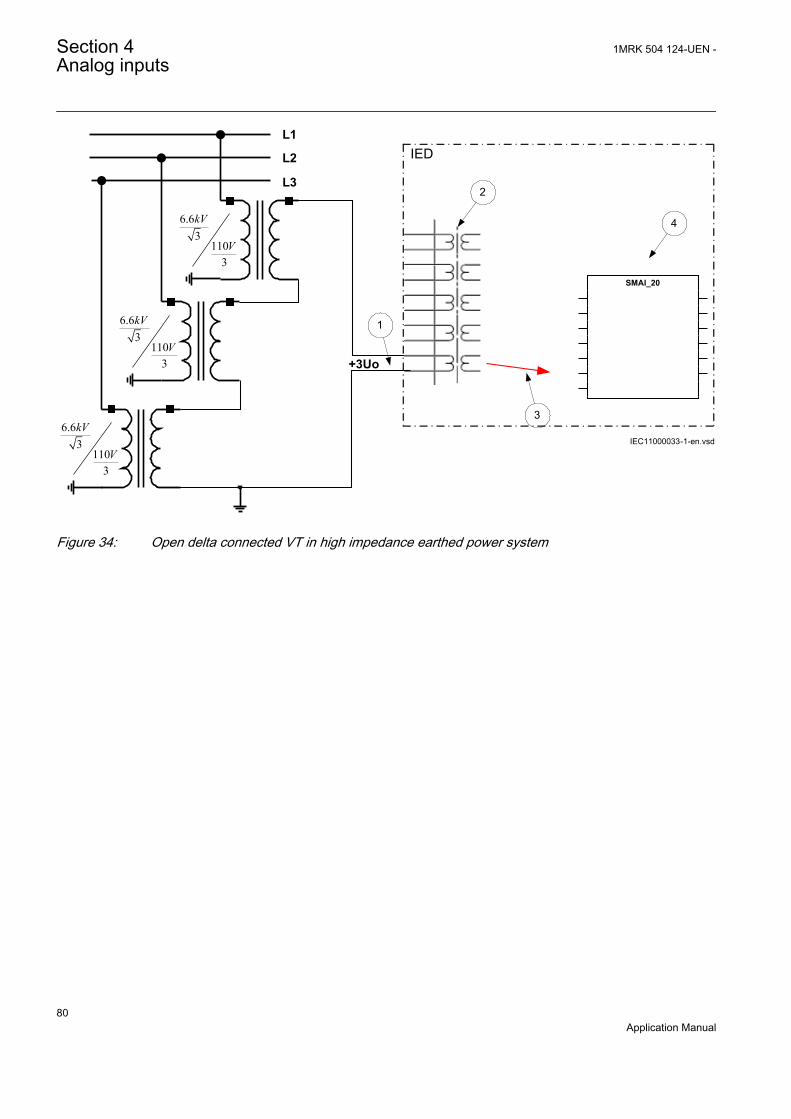
L1IEDL2
L3
6.63
1103
kV
V
+3Uo
6.63
1103
kV
V
6.63
1103
kV
V
1
2
4
3
IEC11000033-1-en.vsd
SMAI_20
IEC11000033 V1 EN
Figure 34: Open delta connected VT in high impedance earthed power system
Section 4 1MRK 504 124-UEN -Analog inputs
80Application Manual
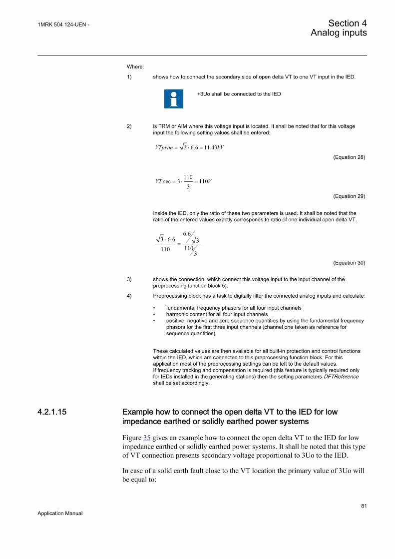
Where:
1) shows how to connect the secondary side of open delta VT to one VT input in the IED.
+3Uo shall be connected to the IED
2) is TRM or AIM where this voltage input is located. It shall be noted that for this voltageinput the following setting values shall be entered:
3 6.6 11.43VTprim kV= × =
EQUATION1923 V1 EN (Equation 28)
110sec 3 110
3VT V= × =
EQUATION1924 V1 EN (Equation 29)
Inside the IED, only the ratio of these two parameters is used. It shall be noted that theratio of the entered values exactly corresponds to ratio of one individual open delta VT.
6.63 6.6 3
1101103
×=
EQUATION1925 V1 EN (Equation 30)
3) shows the connection, which connect this voltage input to the input channel of thepreprocessing function block 5).
4) Preprocessing block has a task to digitally filter the connected analog inputs and calculate:
• fundamental frequency phasors for all four input channels• harmonic content for all four input channels• positive, negative and zero sequence quantities by using the fundamental frequency
phasors for the first three input channels (channel one taken as reference forsequence quantities)
These calculated values are then available for all built-in protection and control functionswithin the IED, which are connected to this preprocessing function block. For thisapplication most of the preprocessing settings can be left to the default values.If frequency tracking and compensation is required (this feature is typically required onlyfor IEDs installed in the generating stations) then the setting parameters DFTReferenceshall be set accordingly.
4.2.1.15 Example how to connect the open delta VT to the IED for lowimpedance earthed or solidly earthed power systems
Figure 35 gives an example how to connect the open delta VT to the IED for lowimpedance earthed or solidly earthed power systems. It shall be noted that this typeof VT connection presents secondary voltage proportional to 3Uo to the IED.
In case of a solid earth fault close to the VT location the primary value of 3Uo willbe equal to:
1MRK 504 124-UEN - Section 4Analog inputs
81Application Manual
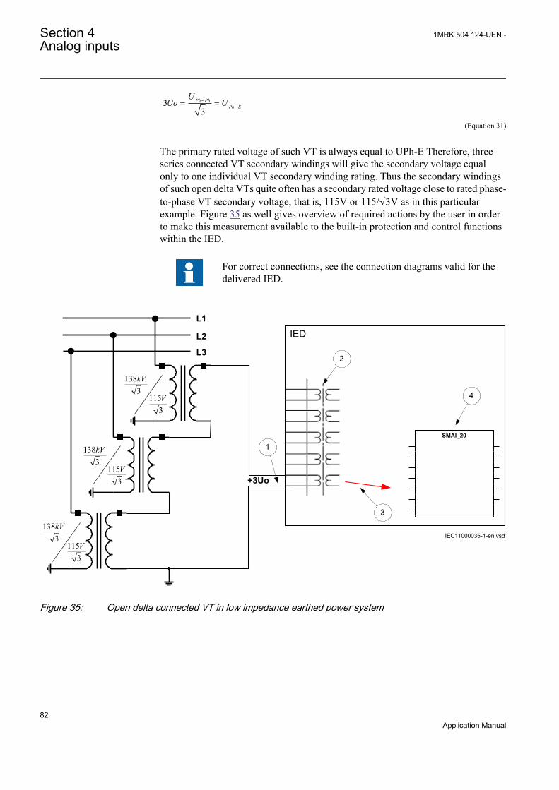
33
Ph PhPh E
UUo U-
-= =
EQUATION1926 V1 EN (Equation 31)
The primary rated voltage of such VT is always equal to UPh-E Therefore, threeseries connected VT secondary windings will give the secondary voltage equalonly to one individual VT secondary winding rating. Thus the secondary windingsof such open delta VTs quite often has a secondary rated voltage close to rated phase-to-phase VT secondary voltage, that is, 115V or 115/√3V as in this particularexample. Figure 35 as well gives overview of required actions by the user in orderto make this measurement available to the built-in protection and control functionswithin the IED.
For correct connections, see the connection diagrams valid for thedelivered IED.
L1
IEDL2
L3
1383
1153
kV
V
+3Uo
1383
1153
kV
V
1383
1153
kV
V
1
2
3
4
IEC11000035-1-en.vsd
SMAI_20
IEC11000035 V1 EN
Figure 35: Open delta connected VT in low impedance earthed power system
Section 4 1MRK 504 124-UEN -Analog inputs
82Application Manual

Where:
1) shows how to connect the secondary side of open delta VT to one VT input in the IED.
+3Uo shall be connected to the IED.
2) is TRM or AIM where this voltage input is located. It shall be noted that for thisvoltage input the following setting values shall be entered:
1383 138
3VTprim kV= × =
EQUATION1928 V1 EN (Equation 32)
115sec 3 115
3VT V= × =
EQUATION1929 V1 EN (Equation 33)
Inside the IED, only the ratio of these two parameters is used. It shall be noted thatthe ratio of the entered values exactly corresponds to ratio of one individual opendelta VT.
138138 3
1151153
=
EQUATION1930 V1 EN (Equation 34)
3) shows the connection, which connect this voltage input to the input channel of thepreprocessing function block 5).
4) preprocessing block has a task to digitally filter the connected analog inputs andcalculate:
• fundamental frequency phasors for all four input channels• harmonic content for all four input channels• positive, negative and zero sequence quantities by using the fundamental
frequency phasors for the first three input channels (channel one taken asreference for sequence quantities)
These calculated values are then available for all built-in protection and controlfunctions within the IED, which are connected to this preprocessing function block.For this application most of the preprocessing settings can be left to the default values.If frequency tracking and compensation is required (this feature is typically requiredonly for IEDs installed in the generating stations) then the setting parametersDFTReference shall be set accordingly.
4.2.1.16 Example how to connect the neutral point VT to the IED
Figure 36 gives an example how to connect the neutral point VT to the IED. It shallbe noted that this type of VT connection presents secondary voltage proportional toUo to the IED.
1MRK 504 124-UEN - Section 4Analog inputs
83Application Manual

In case of a solid earth fault in high impedance earthed or unearthed systems theprimary value of Uo voltage will be equal to:
3Ph Ph
Ph E
UUo U-
-= =
EQUATION1931 V1 EN (Equation 35)
Figure 36 as well gives overview of required actions by the user in order to makethis measurement available to the built-in protection and control functions withinthe IED.
For correct connections, see the connection diagrams valid for thedelivered IED.
L1 L2 L3
IED
6.63
100
kV
V
RUo
1
IEC11000036-1-en.vsd
4
SMAI_20
3
Protected Object
2
IEC11000036 V1 EN
Figure 36: Neutral point connected VT
Section 4 1MRK 504 124-UEN -Analog inputs
84Application Manual
Where:
1) shows how to connect the secondary side of neutral point VT to one VT input in the IED.
+Uo shall be connected to the IED.
2) is TRM or AIM where this voltage input is located. It shall be noted that for this voltageinput the following setting values shall be entered:
6.63.81
3VTprim kV= =
EQUATION1933 V1 EN (Equation 36)
sec 100VT V=
EQUATION1934 V1 EN (Equation 37)
Inside the IED, only the ratio of these two parameters is used. It shall be noted that theratio of the entered values exactly corresponds to ratio of the neutral point VT.
3) shows the connection, which connect this voltage input to the input channel of thepreprocessing function block 5).
4) preprocessing block has a task to digitally filter the connected analog inputs and calculate:
• fundamental frequency phasors for all four input channels• harmonic content for all four input channels• positive, negative and zero sequence quantities by using the fundamental frequency
phasors for the first three input channels (channel one taken as reference forsequence quantities)
These calculated values are then available for all built-in protection and control functionswithin the IED, which are connected to this preprocessing function block. For thisapplication most of the preprocessing settings can be left to the default values.If frequency tracking and compensation is required (this feature is typically required onlyfor IEDs installed in the generating stations) then the setting parameters DFTReferenceshall be set accordingly.
1MRK 504 124-UEN - Section 4Analog inputs
85Application Manual

86
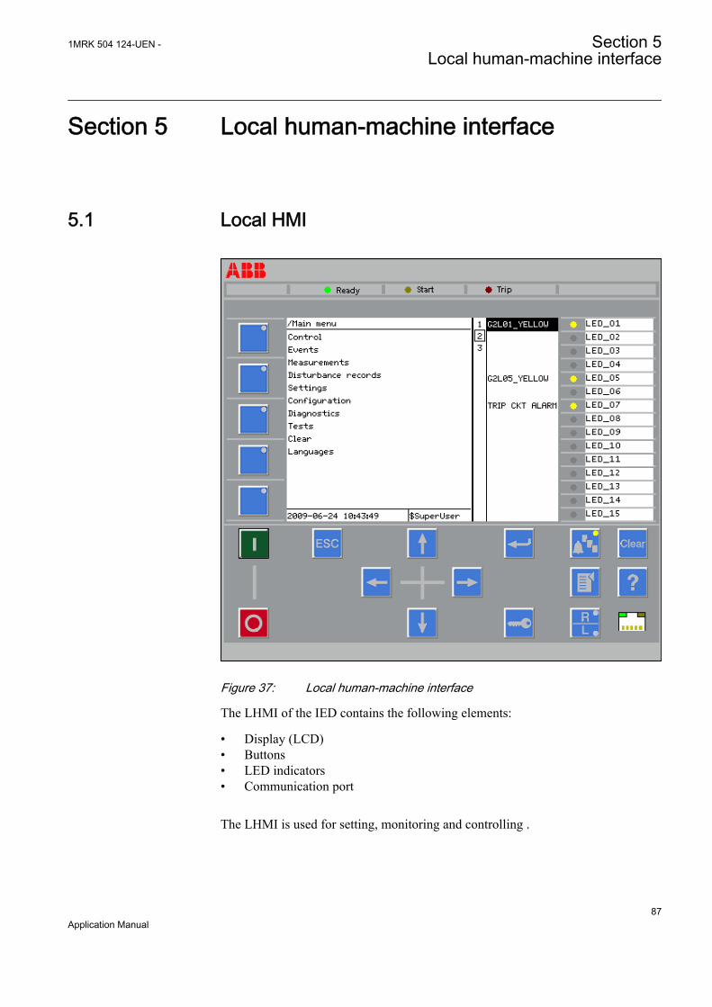
Section 5 Local human-machine interface
5.1 Local HMI
GUID-23A12958-F9A5-4BF1-A31B-F69F56A046C7 V2 EN
Figure 37: Local human-machine interface
The LHMI of the IED contains the following elements:
• Display (LCD)• Buttons• LED indicators• Communication port
The LHMI is used for setting, monitoring and controlling .
1MRK 504 124-UEN - Section 5Local human-machine interface
87Application Manual
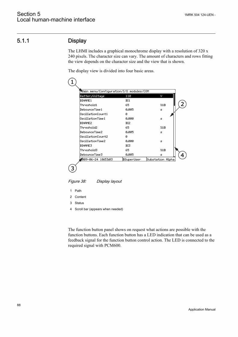
5.1.1 DisplayThe LHMI includes a graphical monochrome display with a resolution of 320 x240 pixels. The character size can vary. The amount of characters and rows fittingthe view depends on the character size and the view that is shown.
The display view is divided into four basic areas.
GUID-97DA85DD-DB01-449B-AD1F-EEC75A955D25 V1 EN
Figure 38: Display layout
1 Path
2 Content
3 Status
4 Scroll bar (appears when needed)
The function button panel shows on request what actions are possible with thefunction buttons. Each function button has a LED indication that can be used as afeedback signal for the function button control action. The LED is connected to therequired signal with PCM600.
Section 5 1MRK 504 124-UEN -Local human-machine interface
88Application Manual
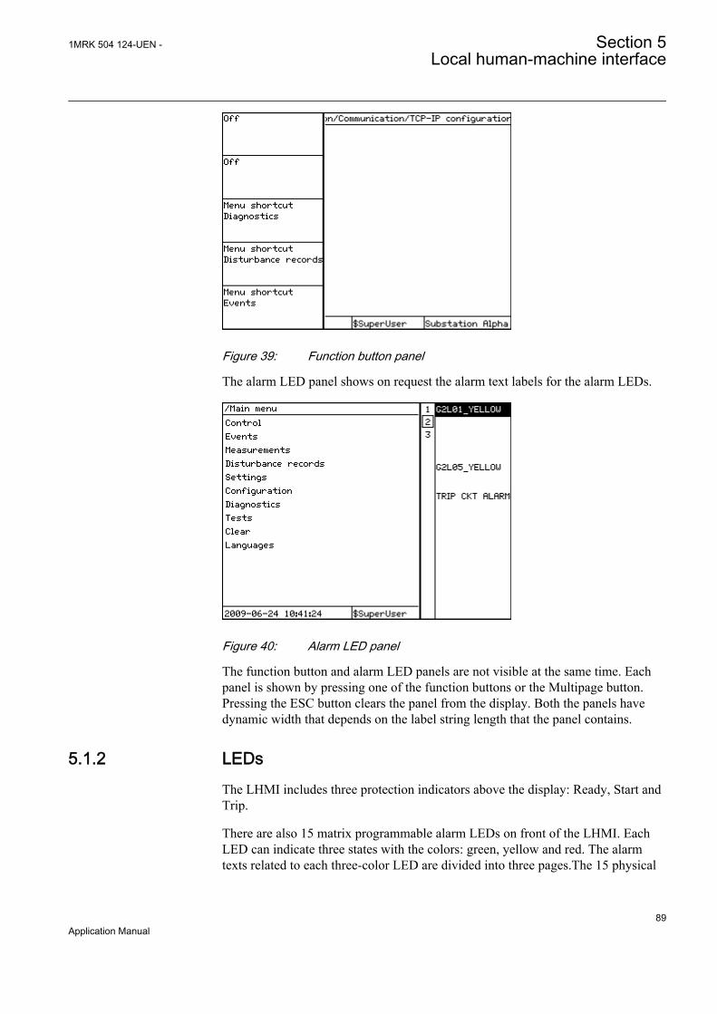
GUID-11D6D98C-A2C9-4B2C-B5E0-FF7E308EC847 V1 EN
Figure 39: Function button panel
The alarm LED panel shows on request the alarm text labels for the alarm LEDs.
GUID-D20BB1F1-FDF7-49AD-9980-F91A38B2107D V1 EN
Figure 40: Alarm LED panel
The function button and alarm LED panels are not visible at the same time. Eachpanel is shown by pressing one of the function buttons or the Multipage button.Pressing the ESC button clears the panel from the display. Both the panels havedynamic width that depends on the label string length that the panel contains.
5.1.2 LEDsThe LHMI includes three protection indicators above the display: Ready, Start andTrip.
There are also 15 matrix programmable alarm LEDs on front of the LHMI. EachLED can indicate three states with the colors: green, yellow and red. The alarmtexts related to each three-color LED are divided into three pages.The 15 physical
1MRK 504 124-UEN - Section 5Local human-machine interface
89Application Manual

three-color LEDs in one LED group can indicate 45 different signals. Altogether,135 signals can be indicated since there are three LED groups. The LEDs can beconfigured with PCM600 and the operation mode can be selected with the LHMIor PCM600.
5.1.3 KeypadThe LHMI keypad contains push-buttons which are used to navigate in differentviews or menus. The push-buttons are also used to acknowledge alarms, resetindications, provide help and switch between local and remote control mode.
The keypad also contains programmable push-buttons that can be configured eitheras menu shortcut or control buttons.
GUID-23A12958-F9A5-4BF1-A31B-F69F56A046C7 V2 EN
Figure 41: LHMI keypad
Section 5 1MRK 504 124-UEN -Local human-machine interface
90Application Manual

GUID-5BF45085-F0E8-4FCB-A941-A2E7FE197EC6 V2 EN
Figure 42: LHMI keypad with object control, navigation and command push-buttons and RJ-45 communication port
1...5 Function button
6 Close
7 Open
8 Escape
9 Left
10 Down
11 Up
12 Right
13 Key
14 Enter
15 Remote/Local
16 Uplink LED
17 Not in use
18 Multipage
19 Menu
20 Clear
21 Help
1MRK 504 124-UEN - Section 5Local human-machine interface
91Application Manual

22 Communication port
5.1.4 Local HMI functionality
5.1.4.1 Protection and alarm indication
Protection indicatorsThe protection indicator LEDs are Ready, Start and Trip.
Configure the disturbance recorder to enable the start and trip LEDs.
Table 8: Ready LED (green)
LED state DescriptionOff Auxiliary supply voltage is disconnected.
On Normal operation.
Flashing Internal fault has occurred.
Table 9: Start LED (yellow)
LED state DescriptionOff Normal operation.
On A protection function has started and an indication message is displayed.
• The start indication is latching and must be reset via communicationor by pressing .
Flashing A flashing yellow LED has a higher priority than a steady yellow LED.The IED is in test mode and protection functions are blocked.
• The indication disappears when the IED is no longer in test modeand blocking is removed.
Table 10: Trip LED (red)
LED state DescriptionOff Normal operation.
On A protection function has tripped and an indication message is displayed.
• The trip indication is latching and must be reset via communicationor by pressing .
Section 5 1MRK 504 124-UEN -Local human-machine interface
92Application Manual
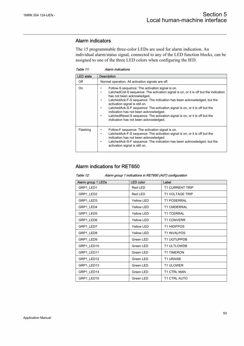
Alarm indicatorsThe 15 programmable three-color LEDs are used for alarm indication. Anindividual alarm/status signal, connected to any of the LED function blocks, can beassigned to one of the three LED colors when configuring the IED.
Table 11: Alarm indications
LED state DescriptionOff Normal operation. All activation signals are off.
On • Follow-S sequence: The activation signal is on.• LatchedColl-S sequence: The activation signal is on, or it is off but the indication
has not been acknowledged.• LatchedAck-F-S sequence: The indication has been acknowledged, but the
activation signal is still on.• LatchedAck-S-F sequence: The activation signal is on, or it is off but the
indication has not been acknowledged.• LatchedReset-S sequence: The activation signal is on, or it is off but the
indication has not been acknowledged.
Flashing • Follow-F sequence: The activation signal is on.• LatchedAck-F-S sequence: The activation signal is on, or it is off but the
indication has not been acknowledged.• LatchedAck-S-F sequence: The indication has been acknowledged, but the
activation signal is still on.
Alarm indications for RET650Table 12: Alarm group 1 indications in RET650 (A07) configuration
Alarm group 1 LEDs LED color LabelGRP1_LED1 Red LED T1 CURRENT TRIP
GRP1_LED2 Red LED T1 VOLTAGE TRIP
GRP1_LED3 Yellow LED T1 POSERRAL
GRP1_LED4 Yellow LED T1 CMDERRAL
GRP1_LED5 Yellow LED T1 TCERRAL
GRP1_LED6 Yellow LED T1 CONVERR
GRP1_LED7 Yellow LED T1 HIDIFPOS
GRP1_LED8 Yellow LED T1 INVALPOS
GRP1_LED9 Green LED T1 UGTUPPDB
GRP1_LED10 Green LED T1 ULTLOWDB
GRP1_LED11 Green LED T1 TIMERON
GRP1_LED12 Green LED T1 URAISE
GRP1_LED13 Green LED T1 ULOWER
GRP1_LED14 Green LED T1 CTRL MAN
GRP1_LED15 Green LED T1 CTRL AUTO
1MRK 504 124-UEN - Section 5Local human-machine interface
93Application Manual

Table 13: Alarm group 2 indications in RET650 (A07) configuration
Alarm group 2 LEDs LED color LabelGRP2_LED1 Red LED T2 CURRENT TRIP
GRP2_LED2 Red LED T2 VOLTAGE TRIP
GRP2_LED3 Yellow LED T2 POSERRAL
GRP2_LED4 Yellow LED T2 CMDERRAL
GRP2_LED5 Yellow LED T2 TCERRAL
GRP2_LED6 Yellow LED T2 CONVERR
GRP2_LED7 Yellow LED T2 HIDIFPOS
GRP2_LED8 Yellow LED T2 INVALPOS
GRP2_LED9 Green LED T2 UGTUPPDB
GRP2_LED10 Green LED T2 ULTLOWDB
GRP2_LED11 Green LED T2 TIMERON
GRP2_LED12 Green LED T2 URAISE
GRP2_LED13 Green LED T2 ULOWER
GRP2_LED14 Green LED T2 CTRL MAN
GRP2_LED15 Green LED T2 CTRL AUTO
Table 14: Alarm group 3 indications in RET650 (A07) configuration
Alarm group 3 LEDs LED color LabelGRP3_LED1 - GRP3_LED12 - -
GRP3_LED13 Yellow LED TRIP CKT1 ALARM
GRP3_LED14 Yellow LED TRIP CKT2 ALARM
GRP3_LED15 Red LED ST BAT ALARM
Yellow LED ST BAT START
5.1.4.2 Parameter management
The LHMI is used to access the IED parameters. Three types of parameters can beread and written.
• Numerical values• String values• Enumerated values
Numerical values are presented either in integer or in decimal format withminimum and maximum values. Character strings can be edited character bycharacter. Enumerated values have a predefined set of selectable values.
5.1.4.3 Front communication
The RJ-45 port in the LHMI enables front communication.
Section 5 1MRK 504 124-UEN -Local human-machine interface
94Application Manual

• The green uplink LED on the left is lit when the cable is successfullyconnected to the port.
GUID-D71BA06D-3769-4ACB-8A32-5D02EA473326 V1 EN
Figure 43: RJ-45 communication port and green indicator LED
1 RJ-45 connector
2 Green indicator LED
When a computer is connected to the IED front port with a crossed-over cable, theIED's DHCP server for the front interface assigns an IP address to the computer ifDHCPServer = On. The default IP address for the front port is 10.1.150.3.
Do not connect the IED front port to LAN. Connect only a singlelocal PC with PCM600 to front port.
5.1.4.4 Single-line diagram
1MRK 504 124-UEN - Section 5Local human-machine interface
95Application Manual

Single-line diagram for RET650
IEC10000182 V1 EN
Figure 44: Single-line diagram for RET650 (A01)
Section 5 1MRK 504 124-UEN -Local human-machine interface
96Application Manual
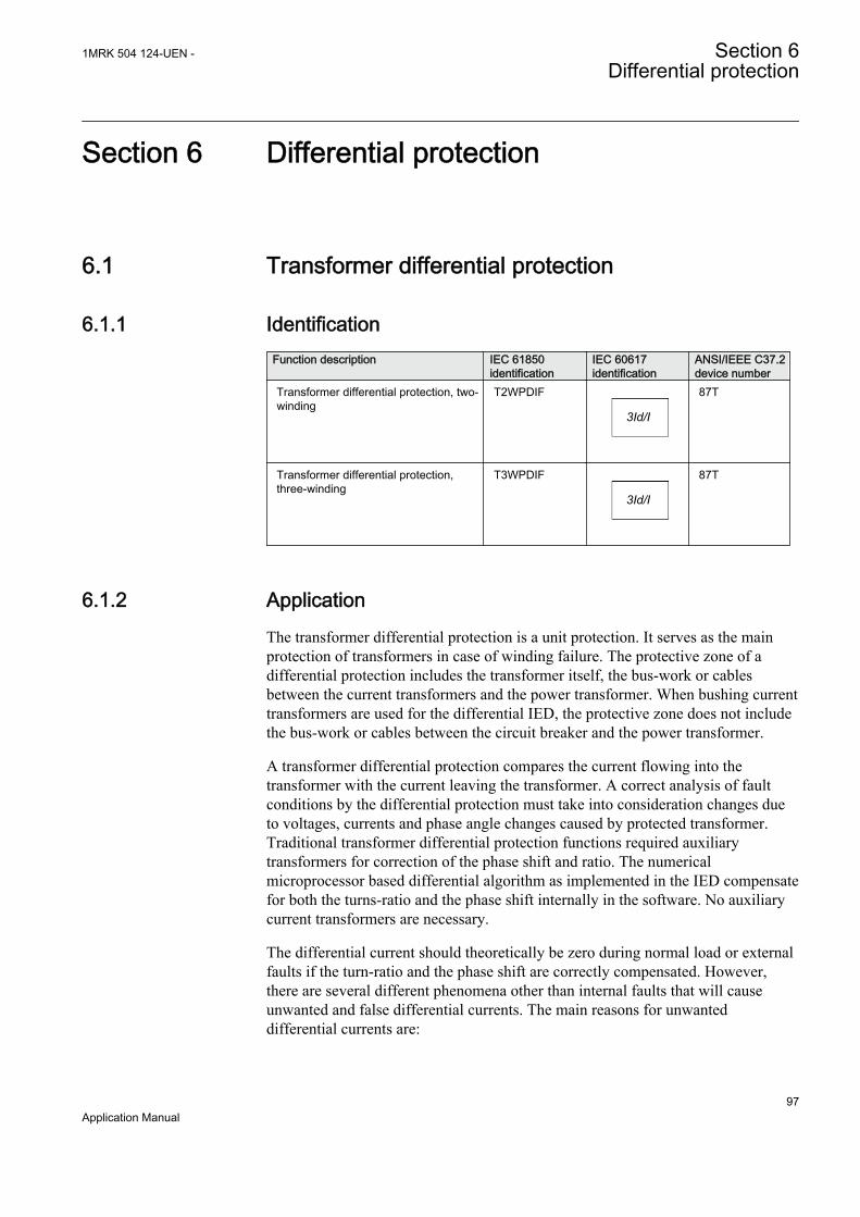
Section 6 Differential protection
6.1 Transformer differential protection
6.1.1 IdentificationFunction description IEC 61850
identificationIEC 60617identification
ANSI/IEEE C37.2device number
Transformer differential protection, two-winding
T2WPDIF
3Id/I
SYMBOL-BB V1 EN
87T
Transformer differential protection,three-winding
T3WPDIF
3Id/I
SYMBOL-BB V1 EN
87T
6.1.2 ApplicationThe transformer differential protection is a unit protection. It serves as the mainprotection of transformers in case of winding failure. The protective zone of adifferential protection includes the transformer itself, the bus-work or cablesbetween the current transformers and the power transformer. When bushing currenttransformers are used for the differential IED, the protective zone does not includethe bus-work or cables between the circuit breaker and the power transformer.
A transformer differential protection compares the current flowing into thetransformer with the current leaving the transformer. A correct analysis of faultconditions by the differential protection must take into consideration changes dueto voltages, currents and phase angle changes caused by protected transformer.Traditional transformer differential protection functions required auxiliarytransformers for correction of the phase shift and ratio. The numericalmicroprocessor based differential algorithm as implemented in the IED compensatefor both the turns-ratio and the phase shift internally in the software. No auxiliarycurrent transformers are necessary.
The differential current should theoretically be zero during normal load or externalfaults if the turn-ratio and the phase shift are correctly compensated. However,there are several different phenomena other than internal faults that will causeunwanted and false differential currents. The main reasons for unwanteddifferential currents are:
1MRK 504 124-UEN - Section 6Differential protection
97Application Manual
• mismatch due to varying tap changer positions• different characteristics, loads and operating conditions of the current
transformers• zero sequence currents that only flow on one side of the power transformer• normal magnetizing currents• magnetizing inrush currents• overexcitation magnetizing currents
6.1.3 Setting guidelinesThe parameters for the Transformer differential protection function are set via thelocal HMI or Protection and Control IED Manager ( PCM600).
Base IED values for primary current (setting IBase), primary voltage (settingUBase) and primary power (setting SBase) for a particular winding are set in aGlobal base values for settings function GBASVAL. Settings GlobalBaseSelW1,GlobalBaseSelW2 and GlobalBaseSelW3 are used to select the correspondingGBASVAL function for reference of base values.
6.1.3.1 Inrush restraint methods
With a combination of the second harmonic restraint and the waveform restraintmethods it is possibly to get a protection with high security and stability againstinrush effects and at the same time maintain high performance in case of heavyinternal faults even if the current transformers are saturated. Both these restraintmethods are used by the IED. The second harmonic restraint function has a settablelevel. If the ratio of the second harmonic to fundamental harmonic in thedifferential current is above the settable limit, the operation of the differentialprotection is restrained. It is recommended to set parameter I2/I1Ratio = 15% asdefault value in case no special reasons exist to choose other value.
6.1.3.2 Overexcitation restraint method
Overexcitation current contains odd harmonics, because the waveform issymmetrical about the time axis. As the third harmonic currents cannot flow into adelta winding, the fifth harmonic is the lowest harmonic which can serve as acriterion for overexcitation. Differential protection function is provided with a fifthharmonic restraint to prevent the protection from operation during anoverexcitation condition of a power transformer. If the ratio of the fifth harmonic tofundamental harmonic in the differential current is above a settable limit theoperation is restrained. It is recommended to use I5/I1Ratio = 25% as default valuein case no special reasons exist to choose another setting. Transformers likely to beexposed to overvoltage or underfrequency conditions (that is, generator step-uptransformers in power stations) should be provided with an overexcitationprotection based on V/Hz to achieve trip before the core thermal limit is reached.
Section 6 1MRK 504 124-UEN -Differential protection
98Application Manual
6.1.3.3 Cross-blocking between phases
Basic definition of the cross-blocking is that one of the three phases can blockoperation (that is, tripping) of the other two phases due to the harmonic pollution ofthe differential current in that phase (waveform, 2nd or 5th harmonic content). Inthe algorithm the user can control the cross-blocking between the phases via thesetting parameter CrossBlockEn. When parameter CrossBlockEn is set to On, crossblocking between phases will be introduced. There are no time related settingsinvolved, but the phase with the operating point above the set bias characteristicwill be able to cross-block other two phases if it is self-blocked by any of thepreviously explained restrained criteria. As soon as the operating point for thisphase is below the set bias characteristic cross blocking from that phase will beinhibited. In this way cross-blocking of the temporary nature is achieved. In shouldbe noted that this is the default (recommended) setting value for this parameter.When parameter CrossBlockEn is set to Off, any cross blocking between phaseswill be disabled.
6.1.3.4 Restrained and unrestrained differential protection
The usual practice for transformer protection is to set the bias characteristic to avalue of at least twice the value of the expected spill current under through faultsconditions. These criteria can vary considerably from application to application andare often a matter of judgment. The second slope is increased to ensure stabilityunder heavy through fault conditions which could lead to increased differentialcurrent due to saturation of current transformers. Default settings for the operatingcharacteristic with IdMin = 0.3pu of the power transformer rated current can berecommended as a default setting in normal applications. If the conditions areknown more in detail, higher or lower sensitivity can be chosen. The selection ofsuitable characteristic should in such cases be based on the knowledge of the classof the current transformers, availability of information on the load tap changerposition, short circuit power of the systems, and so on.
Unrestrained operation level has default value of IdUnre = 10pu, which is typicallyacceptable for most of the standard power transformer applications. However in thefollowing cases these setting need to be changed accordingly:
• For differential applications on HV shunt reactors, due to a fact that there is noheavy through-fault conditions, the unrestrained differential operation levelcan be set to IdUnre = 1.75pu
Overall operating characteristic of transformer differential protection is shown infigure 45.
1MRK 504 124-UEN - Section 6Differential protection
99Application Manual

Section 1
Operate conditionally
UnrestrainedLimit
Section 2 Section 3
Restrain
Operate unconditionally
5
4
3
2
1
00 1 2 3 4 5
IdMin
EndSection1
EndSection2restrain current[ times IBase ]
operate current[ times IBase ]
SlopeSection2
SlopeSection3
en05000187-2.vsdIEC05000187 V2 EN
Figure 45: Representation of the restrained-, and the unrestrained operatecharacteristics
100%Ioperateslope IrestrainD= D ×
EQUATION1246 V1 EN (Equation 38)
and where the restrained characteristic is defined by the settings:
1. IdMin
2. EndSection1
3. EndSection2
4. SlopeSection2
5. SlopeSection3
6.1.3.5 Elimination of zero sequence currents
A differential protection may operate unwanted due to external earth-faults in caseswhere the zero sequence current can flow only on one side of the powertransformer but not on the other side. This is the situation when the zero sequencecurrent cannot be properly transformed to the other side of the power transformer.
Section 6 1MRK 504 124-UEN -Differential protection
100Application Manual
Power transformer connection groups of Yd or Dy type cannot transform the zerosequence current. If a delta winding of a power transformer is earthed via anearthing transformer inside the zone protected by the differential protection therewill be an unwanted differential current in case of an external earth-fault. To makethe overall differential protection insensitive to external earth-faults in thesesituations the zero sequence currents must be eliminated from the powertransformer IED currents, so that they do not appear as the differential currents.This had once been achieved by means of interposing auxiliary currenttransformers. The elimination of zero sequence current is done numerically and noauxiliary transformers or zero sequence traps are necessary. Instead it is necessaryto eliminate the zero sequence current from every individual winding by propersetting of setting parameters ZSCurrSubtrWx=Off or On.
6.1.3.6 External/Internal fault discriminator
The internal/external fault discriminator operation is based on the relative positionof the two phasors (in case of two-winding transformer) representing W1 and W2negative sequence current contributions. It practically performs directionalcomparison between these two phasors.
In order to perform directional comparison of the two phasors their magnitudesmust be high enough so that one can be sure that they are due to a fault. On theother hand, in order to guarantee a good sensitivity of the internal/external faultdiscriminator, the value of this minimum limit must not be too high. Therefore thislimit value, called IMinNegSeq, is settable in the range from 1% to 20% of thedifferential protections IBase current, which is in our case the power transformerHV side rated current. The default value is 4%. Only if magnitudes of bothnegative sequence current contributions are above the set limit, the relative positionbetween these two phasors is checked. If either of the negative sequence currentcontributions, which should be compared, is too small (less than the set value forIMinNegSeq), no directional comparison is made in order to avoid the possibility toproduce a wrong decision. This magnitude check, as well guarantee stability of thealgorithm, when power transformer is energized.
The setting NegSeqROA represents the so-called Relay Operate Angle, whichdetermines the boundary between the internal and external fault regions. It can beselected in the range from 30 degrees to 90 degrees, with a step of 1 degree. Thedefault value is 60 degrees. The default setting 60 degrees somewhat favorssecurity in comparison to dependability. If the user has no well-justified reason foranother value, 60 degrees shall be applied.
If the above condition concerning magnitudes is fulfilled, the internal/external faultdiscriminator compares the relative phase angle between the negative sequencecurrent contributions from the HV side and LV side of the power transformer usingthe following two rules:
1MRK 504 124-UEN - Section 6Differential protection
101Application Manual

• If the negative sequence currents contributions from HV and LV sides are inphase or at least in the internal fault region, the fault is internal.
• If the negative sequence currents contributions from HV and LV sides are 180degrees out of phase or at least in the external fault region, the fault is external.
Under external fault condition and with no current transformer saturation, therelative angle is theoretically equal to 180 degrees. During internal fault and withno current transformer saturation, the angle shall ideally be 0 degrees, but due topossible different negative sequence source impedance angles on HV and LV sideof power transformer, it may differ somewhat from the ideal zero value.
As the internal/external fault discriminator has proved to be very reliable, it hasbeen given a great power. If, for example, a fault has been detected, that is,PICKUP signals set by ordinary differential protection, and at the same time theinternal/external fault discriminator characterized this fault as internal, then anyeventual block signals produced by either the harmonic or the waveform restraints,are ignored. If the bias current is more than 110% of IBase, the negative sequencethreshold (IMinNegSeq) is increased internally. This assures the response times ofthe new and advanced differential protection below one power system cycle (below20 ms for 50 Hz system) for all more sever internal faults. Even for heavy internalfaults with severely saturated current transformers this new differential protectionoperates well below one cycle because the harmonic distortions in the differentialcurrents do not slow down the differential protection operation. The sensitivenegative sequence current based differential protection, which is supposed to detectminor internal faults, and where the speed is not so essential, but instead stabilityagainst unwanted trips, is restrained when bias current is more than 150% of IBase.For the sensitive negative sequence protection to be reactivated, the bias currentmust drop back below 110% of IBase. The sensitive negative sequence protectionis always restrained by the harmonic restraint.
External faults happen ten to hundred times more often than internal ones as far asthe power transformers are concerned. If a disturbance has been detected and theinternal/external fault discriminator characterized this fault as external fault, theadditional criteria are posed on the differential algorithm before its trip is allowed.This assures high algorithm stability during external faults. However, in the sametime the differential function is still capable to trip for evolving faults.
The principle of the internal/external fault discriminator can be extended to powertransformers and autotransformers with three windings. If all three windings areconnected to their respective networks, then three directional comparisons can bedone, but only two comparisons are necessary in order to positively determine theposition of the fault with respect to the protected zone. The directionalcomparisons, which are possible, are: W1 - (W2 + W3); W2 - (W1 + W3); W3 -(W1 + W2). The rule applied by the internal/external fault discriminator in case ofthree-winding power transformers is:
• If all comparisons indicate an internal fault, then it is an internal fault.• If any comparison indicates an external fault, then it is an external fault
Section 6 1MRK 504 124-UEN -Differential protection
102Application Manual
If one of the windings is not connected, the algorithm automatically reduces to thetwo-winding version. Nevertheless, the whole power transformer is protected,inclusive the non-connected winding.
6.1.3.7 Differential current alarm
Differential protection continuously monitors the level of the fundamentalfrequency differential currents and gives an alarm if the pre-set value issimultaneously exceeded in all three phases. Set the time delayed defined byparameter tAlarmDelay two times longer than the load tap changer mechanicaloperating time (For example, typical setting value 10s).
6.1.3.8 Switch onto fault feature
Transformer differential (TW2PDIF for two winding and TW3PDIF for threewinding) function in the IED has a built-in, advanced switch onto fault feature.This feature can be enabled or disabled by a setting parameter SOTFMode. WhenSOTFMode = On this feature is enabled. However it shall be noted that when thisfeature is enabled it is not possible to test 2nd harmonic blocking feature by simplyinjecting one current with superimposed second harmonic. In that case the switchon to fault feature will operate and differential protection will trip. However forreal inrush case the differential protection function will properly restrain fromoperation.
For more information about operating principles of the switch onto fault featureplease read the “Technical Manual”..
6.1.4 Setting example
6.1.4.1 Summary and conclusions
The IED can be used for differential protection of three-phase power transformerswith main CTs either star or delta connected. However the IED has been designedwith assumption that all main CTS are star connected. The IED can be used inapplications where main CTs are delta connected. For such applications thefollowing shall be kept in mind:
1. Ratio for delta connected CTs shall be set √(3)=1.732 times smaller thenactual individual phase CT ratio.
2. Power transformer vector group shall be typically set as Yy0 because thecompensation for power transformer actual phase shift is provided by externaldelta CT connection.
3. Zero sequence current is eliminated by main CT delta connection. Thus onsides where CTs are connected in delta the zero sequence current eliminationshall be set to Off in the IED.
1MRK 504 124-UEN - Section 6Differential protection
103Application Manual

The following table summarizes the most commonly used star-delta vector grouparound the world and provides information about required type of main CT deltaconnection on the star sides of the protected transformer.
IEC vector group Positive sequence no-loadvoltage phasor diagram
Required delta CT connection type on star sideof the protected power transformer and internalvector group setting in the IED
YNd1 Y
IEC06000559 V1 EN
Yy0
Dyn1Y
IEC06000560 V1 EN
Yy0
YNd11 Y
IEC06000561 V1 EN
Yy0
Dyn11
Y
IEC06000562 V1 EN
Yy0
YNd5 Y
IEC06000563 V1 EN
Yy6
Dyn5
YIEC06000564 V1 EN
Yy6
Section 6 1MRK 504 124-UEN -Differential protection
104Application Manual

6.2 Restricted earth-fault protection, low impedanceREFPDIF
6.2.1 IdentificationFunction description IEC 61850
identificationIEC 60617identification
ANSI/IEEE C37.2device number
Restricted earth fault protection, lowimpedance
REFPDIF
IdN/I
SYMBOL-AA V1 EN
87N
6.2.2 ApplicationBreakdown of the insulation between a phase conductor and earth in an effectivelyor low impedance earthed power system results in a large fault current. Abreakdown of the insulation between a transformer winding and the core or thetank may result in a large fault current which causes severe damage to the windingsand the transformer core. A high gas pressure may develop, damaging thetransformer tank.
Fast and sensitive detection of earth faults in a power transformer winding can beobtained in solidly earthed or low impedance earthed networks by the restrictedearth fault protection. The only requirement is that the power transformer windingis connected to earth in the star point (in case of star-connected windings) or viaseparate earthing transformer (in case of delta-connected windings).
Restricted earth fault protection, low impedance function REFPDIF is used as aunit protection function. It protects the power transformer winding against thefaults involving earth. Please note that single phase-to-earth faults are the mostcommon fault-types in transformers. A sensitive earth-fault protection is thereforedesirable.
Restricted earth fault protection is the fastest and the most sensitive protection apower transformer winding can have and will detect faults such as:
• earth faults in the transformer winding when the network is earthed through animpedance
• earth faults in the transformer winding in solidly earthed network when thepoint of the fault is close to the winding star point.
The restricted earth fault protection is not affected, as differential protection, withthe following power transformer related phenomena:
1MRK 504 124-UEN - Section 6Differential protection
105Application Manual

• magnetizing inrush currents• overexcitation magnetizing currents• load tap changer• external and internal phase faults which do not involve earth• symmetrical overload conditions
Due to its properties, REFPDIF is often used as a main protection of thetransformer winding for all faults involving earth.
6.2.2.1 Application examples
Transformer winding, solidly earthedThe most common application is on a solidly earthed transformer winding. Theconnection is shown in figure 46.
IEC09000109-1-en.vsd
IdN/I
REFPDIF
I3P
I3PW1CT1
IEC09000109 V1 EN
Figure 46: Connection of Restricted earth fault, low impedance functionREFPDIF for a fully insulated, directly (solidly) earthed transformer
Transformer winding, earthed through Z-0 earthing transformerA common application is for low reactance earthed transformer where the earthingis through separate Z-0 earthing transformers. The fault current is then limited totypical 800 to 2000A for each transformer. The connection of Restricted earth faultprotection, low impedance REFPDIF for this application is shown in figure 47.
Section 6 1MRK 504 124-UEN -Differential protection
106Application Manual
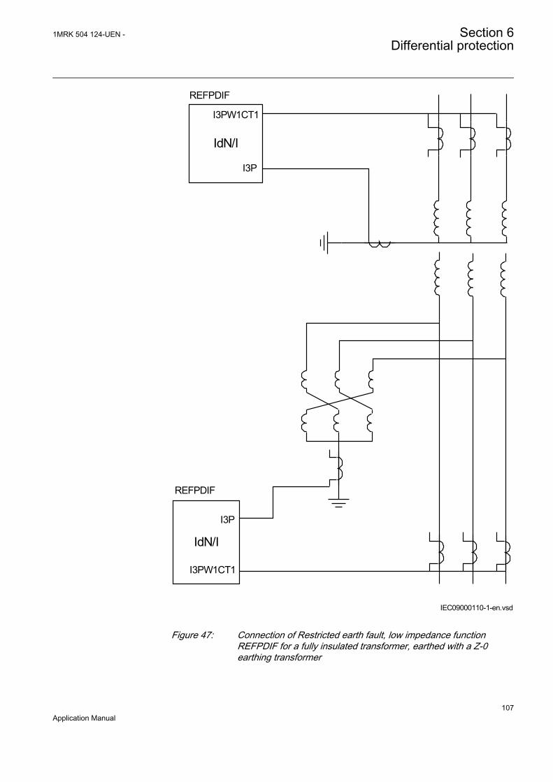
IdN/I
REFPDIF
IdN/I
REFPDIF
I3P
I3PW1CT1
I3P
I3PW1CT1
IEC09000110-1-en.vsdIEC09000110 V1 EN
Figure 47: Connection of Restricted earth fault, low impedance functionREFPDIF for a fully insulated transformer, earthed with a Z-0earthing transformer
1MRK 504 124-UEN - Section 6Differential protection
107Application Manual
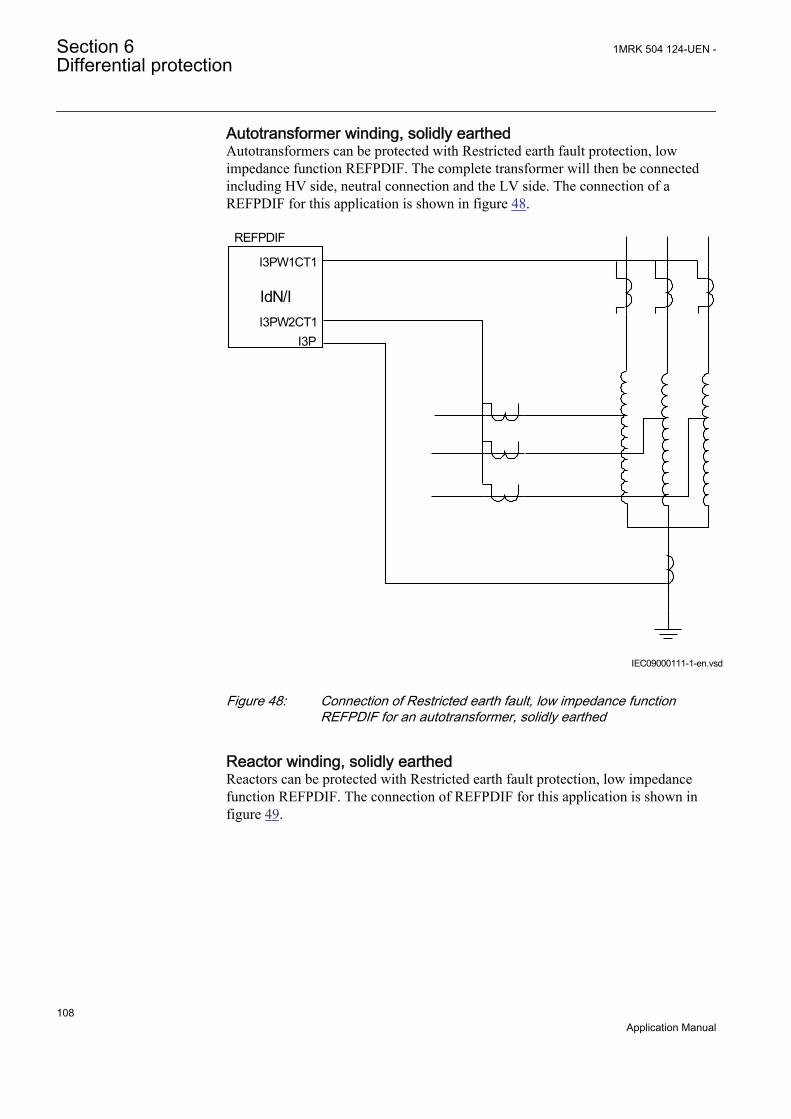
Autotransformer winding, solidly earthedAutotransformers can be protected with Restricted earth fault protection, lowimpedance function REFPDIF. The complete transformer will then be connectedincluding HV side, neutral connection and the LV side. The connection of aREFPDIF for this application is shown in figure 48.
IEC09000111-1-en.vsd
IdN/I
REFPDIF
I3P
I3PW1CT1
I3PW2CT1
IEC09000111 V1 EN
Figure 48: Connection of Restricted earth fault, low impedance functionREFPDIF for an autotransformer, solidly earthed
Reactor winding, solidly earthedReactors can be protected with Restricted earth fault protection, low impedancefunction REFPDIF. The connection of REFPDIF for this application is shown infigure 49.
Section 6 1MRK 504 124-UEN -Differential protection
108Application Manual
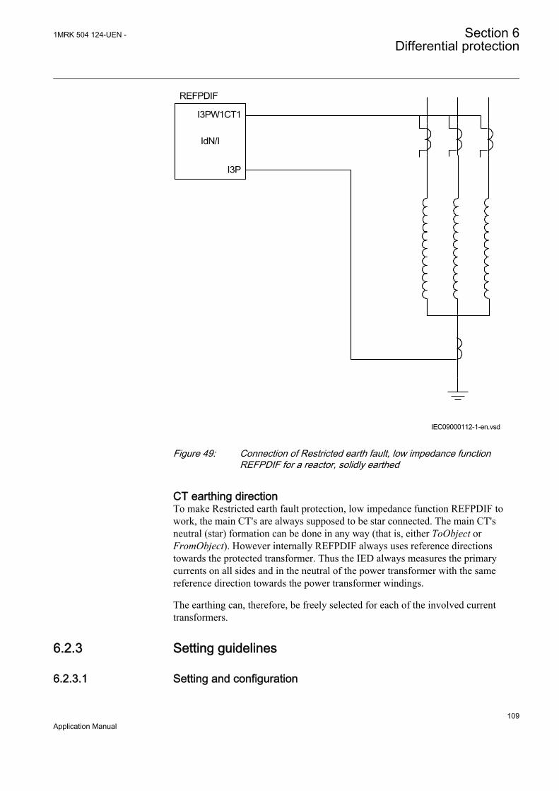
IEC09000112-1-en.vsd
IdN/I
REFPDIF
I3P
I3PW1CT1
IEC09000112 V1 EN
Figure 49: Connection of Restricted earth fault, low impedance functionREFPDIF for a reactor, solidly earthed
CT earthing directionTo make Restricted earth fault protection, low impedance function REFPDIF towork, the main CT's are always supposed to be star connected. The main CT'sneutral (star) formation can be done in any way (that is, either ToObject orFromObject). However internally REFPDIF always uses reference directionstowards the protected transformer. Thus the IED always measures the primarycurrents on all sides and in the neutral of the power transformer with the samereference direction towards the power transformer windings.
The earthing can, therefore, be freely selected for each of the involved currenttransformers.
6.2.3 Setting guidelines
6.2.3.1 Setting and configuration
1MRK 504 124-UEN - Section 6Differential protection
109Application Manual

Recommendation for analog inputs
• I3P• Connect the neutral current here
I3PW1CT1: Phase currents for winding 1 first current transformer set.
I3PW2CT1: Phase currents for winding 2 first current transformer set. Used atAutotransformers.
Recommendation for input signalsRefer to the default factory configuration for examples of configuration.
BLOCK: The input will block the operation of the function. Can be used forexample, to for a limited time block the operation during special service conditions.
Recommendation for output signalsRefer to the default factory configuration for examples of configuration.
START: The start output indicates that Idiff is in the operate region of the Idiff/Ibias characteristic. It can be used to initiate disturbance recorder.
TRIP: The trip output is activated when all operating criteria are fulfilled.
DIROK: The output is activated when the directional criteria has been fulfilled.Output can be used for information purpose normally during testing. It can, forexample, be checked from the debug tool or connected as an event to the event log.
BLK2H: The output is activated when the function is blocked due to too high levelof second harmonic. Output can be used for information purpose normally duringtesting. It can, for example, be checked from the debug tool or connected as anevent to the event log.
6.2.3.2 Settings
The parameters for Restricted earth fault protection, low impedance functionREFPDIF are set via the local HMI or PCM600.
Common base IED values for primary current (IBase), primary voltage (UBase)and primary power (SBase) are set in a Global base values for settings functionGBASVAL. Setting GlobalBaseSel is used to select a GBASVAL function forreference of base values.
Operation: The operation of REFPDIF can be switched On/Off.
IdMin: The setting gives the minimum operation value. The setting is in percent ofthe IBase value. The neutral current must always be bigger than or equal to half ofthis value. A normal setting is 30% of power transformer rated current for thewinding for the solidly earthed winding.
Section 6 1MRK 504 124-UEN -Differential protection
110Application Manual

6.3 1Ph High impedance differential protection HZPDIF
6.3.1 Identification
Function description IEC 61850identification
IEC 60617identification
ANSI/IEEE C37.2device number
1Ph High impedance differentialprotection HZPDIF Id
SYMBOL-CC V2 EN
87
6.3.2 ApplicationThe 1Ph High impedance differential protection function HZPDIF can be used as arestricted earth fault protection.
Id
IEC05000177-2-en.vsdIEC05000177 V2 EN
Figure 50: Application of a 1Ph High impedance differential protectionHZPDIF function
6.3.2.1 The basics of the high impedance principle
The high impedance differential protection principle has been used for many yearsand is well documented. The operating characteristic provides very good sensitivityand high speed operation. One main benefit offered by the principle is an absolutestability (that is, non-operation) for external faults even in the presence of heavyCT saturation. The principle is based on the CT secondary current circulatingbetween involved current transformers and not through the IED due to its high
1MRK 504 124-UEN - Section 6Differential protection
111Application Manual
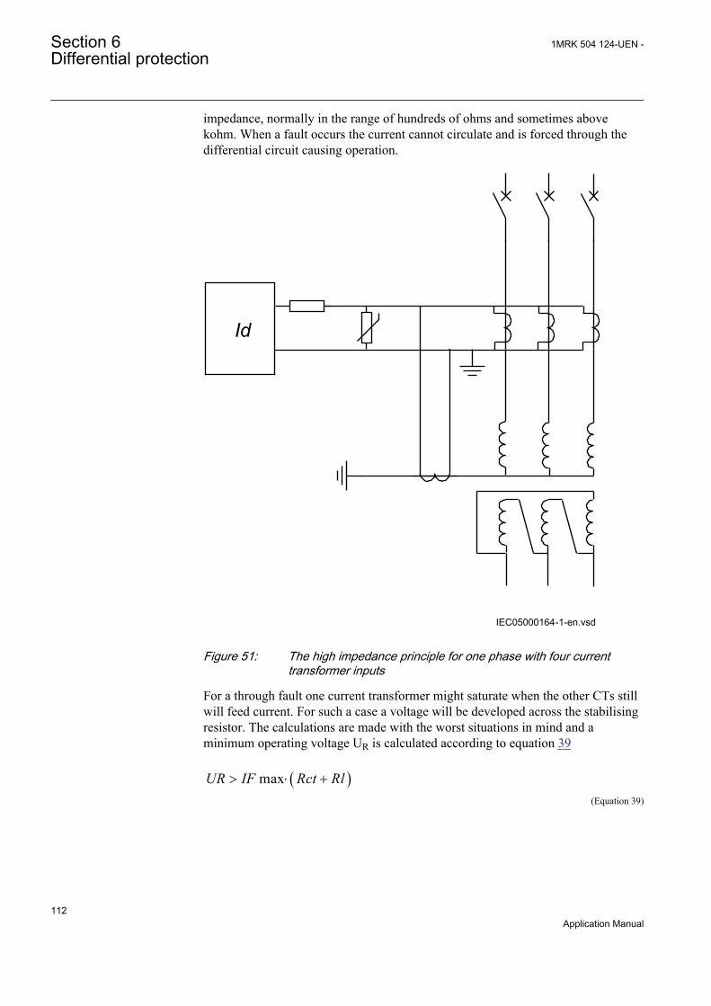
impedance, normally in the range of hundreds of ohms and sometimes abovekohm. When a fault occurs the current cannot circulate and is forced through thedifferential circuit causing operation.
Id
IEC05000164-1-en.vsdIEC05000164 V2 EN
Figure 51: The high impedance principle for one phase with four currenttransformer inputs
For a through fault one current transformer might saturate when the other CTs stillwill feed current. For such a case a voltage will be developed across the stabilisingresistor. The calculations are made with the worst situations in mind and aminimum operating voltage UR is calculated according to equation 39
( )maxUR IF Rct Rl> × +EQUATION1531 V1 EN (Equation 39)
Section 6 1MRK 504 124-UEN -Differential protection
112Application Manual
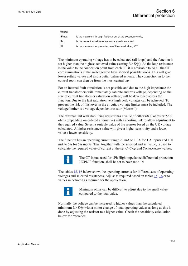
where:
IFmax is the maximum through fault current at the secondary side,
Rct is the current transformer secondary resistance and
RI is the maximum loop resistance of the circuit at any CT.
The minimum operating voltage has to be calculated (all loops) and the function isset higher than the highest achieved value (setting U>Trip). As the loop resistanceis the value to the connection point from each CT it is advisable to do all the CTcore summations in the switchgear to have shortest possible loops. This will givelower setting values and also a better balanced scheme. The connection in to thecontrol room can then be from the most central bay.
For an internal fault circulation is not possible and due to the high impedance thecurrent transformers will immediately saturate and rms voltage, depending on thesize of current transformer saturation voltage, will be developed across thefunction. Due to the fast saturation very high peak voltages can be achieved. Toprevent the risk of flashover in the circuit, a voltage limiter must be included. Thevoltage limiter is a voltage dependent resistor (Metrosil).
The external unit with stabilizing resistor has a value of either 6800 ohms or 2200ohms (depending on ordered alternative) with a shorting link to allow adjustment tothe required value. Select a suitable value of the resistor based on the UR voltagecalculated. A higher resistance value will give a higher sensitivity and a lowervalue a lower sensitivity.
The function has an operating current range 20 mA to 1.0A for 1 A inputs and 100mA to 5A for 5A inputs. This, together with the selected and set value, is used tocalculate the required value of current at the set U>Trip and SeriesResitor values.
The CT inputs used for 1Ph High impedance differential protectionHZPDIF function, shall be set to have ratio 1:1
The tables 15, 16 below show, the operating currents for different sets of operatingvoltages and selected resistances. Adjust as required based on tables 15, 16 or tovalues in between as required for the application.
Minimum ohms can be difficult to adjust due to the small valuecompared to the total value.
Normally the voltage can be increased to higher values than the calculatedminimum U>Trip with a minor change of total operating values as long as this isdone by adjusting the resistor to a higher value. Check the sensitivity calculationbelow for reference.
1MRK 504 124-UEN - Section 6Differential protection
113Application Manual
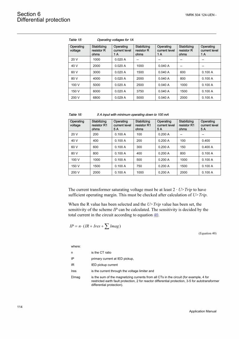
Table 15: Operating voltages for 1A
Operatingvoltage
Stabilizingresistor Rohms
Operatingcurrent level1 A
Stabilizingresistor Rohms
Operatingcurrent level1 A
Stabilizingresistor Rohms
Operatingcurrent level1 A
20 V 1000 0.020 A -- -- -- --
40 V 2000 0.020 A 1000 0.040 A -- --
60 V 3000 0.020 A 1500 0.040 A 600 0.100 A
80 V 4000 0.020 A 2000 0.040 A 800 0.100 A
100 V 5000 0.020 A 2500 0.040 A 1000 0.100 A
150 V 6000 0.020 A 3750 0.040 A 1500 0.100 A
200 V 6800 0.029 A 5000 0.040 A 2000 0.100 A
Table 16: 5 A input with minimum operating down to 100 mA
Operatingvoltage
Stabilizingresistor R1ohms
Operatingcurrent level5 A
Stabilizingresistor R1ohms
Operatingcurrent level5 A
Stabilizingresistor R1ohms
Operatingcurrent level5 A
20 V 200 0.100 A 100 0.200 A -- --
40 V 400 0.100 A 200 0.200 A 100 0.400
60 V 600 0.100 A 300 0.200 A 150 0.400 A
80 V 800 0.100 A 400 0.200 A 800 0.100 A
100 V 1000 0.100 A 500 0.200 A 1000 0.100 A
150 V 1500 0.100 A 750 0.200 A 1500 0.100 A
200 V 2000 0.100 A 1000 0.200 A 2000 0.100 A
The current transformer saturating voltage must be at least 2 · U>Trip to havesufficient operating margin. This must be checked after calculation of U>Trip.
When the R value has been selected and the U>Trip value has been set, thesensitivity of the scheme IP can be calculated. The sensitivity is decided by thetotal current in the circuit according to equation 40.
( )IP n IR Ires lmag= × + +åEQUATION1747 V1 EN (Equation 40)
where:
n is the CT ratio
IP primary current at IED pickup,
IR IED pickup current
Ires is the current through the voltage limiter and
ΣImag is the sum of the magnetizing currents from all CTs in the circuit (for example, 4 forrestricted earth fault protection, 2 for reactor differential protection, 3-5 for autotransformerdifferential protection).
Section 6 1MRK 504 124-UEN -Differential protection
114Application Manual

It should be remembered that the vectorial sum of the currents must be used (IEDs,Metrosil and resistor currents are resistive). The current measurement shall beinsensitive to DC component in fault current to allow a use of only the ACcomponents of the fault current in the above calculations.
The voltage dependent resistor (Metrosil) characteristic is shown in figure 55.
Series resistor thermal capacityThe series resistor is dimensioned for 200 W. Preferable the U>Trip2/SeriesResistor should always be lower than 200 W to allow continuous activationon during testing. If this value is exceeded, testing should be done with transient faults.
1MRK 504 124-UEN - Section 6Differential protection
115Application Manual

I>
R
Rres
Rl
Rct Rct
Rl
UR
a) Through load situation
b) Through fault situation
UR
UR
c) Internal faults
UR
Protected Object
IEC05000427-2-en.vsd
IEC05000427 V2 EN
Figure 52: The high impedance principle for one phase with two currenttransformer inputs
Section 6 1MRK 504 124-UEN -Differential protection
116Application Manual
6.3.3 Connection examples
WARNING! USE EXTREME CAUTION! Dangerously highvoltages might be present on this equipment, especially on the platewith resistors. Do any maintenance ONLY if the primary objectprotected with this equipment is de-energized. If required bynational law or standard, enclose the plate with resistors with aprotective cover or in a separate box.
6.3.3.1 Connections for 1Ph restricted earth fault and high impedancedifferential protection
Restricted earth fault protection REFis a typical application for 1Ph Highimpedance differential protection HZPDIF. Typical CT connections for highimpedance based REF protection scheme are shown in figure 53.
L1(A)
L2(B)
L3(C)
Protected Object
CT 1500/5Star/Wye
Connected
7
8
9
10
11
12
1
2
3
4
5
6
AI01 (I)
AI02 (I)
AI03 (I)
AI04 (I)
AI05 (I)
AI06 (I)
6
7
8
IED
X1
R1
12
4 5
U R2
13
4
2
1 2 3
N
1-Ph Plate with Metrosil and Resistor
23
5
4
9
N
L1(A)
L2(B)
L3(C)
CT
1500
/5
1
IEC07000194_2_en.vsd
AI3P
AI1
AI2
AI3
AI4
AIN
SMAI2
BLOCK
^GRP2L1
^GRP2L2
^GRP2L3
^GRP2N
TYPE
IEC07000194 V2 EN
Figure 53: CT connections for restricted earth fault protection
Pos Description
1 Scheme earthing point
Note that it is of outmost importance to insure that only one earthing pointexist in such scheme.
2 One-phase plate with setting resistor and metrosil.
1MRK 504 124-UEN - Section 6Differential protection
117Application Manual

3 Necessary connection for the metrosil. Shown connections are applicable for both types of one-phase plate.
4 Position of optional test switch for secondary injection into the high impedance differential IED.
5 Necessary connection for setting resistor. Shown connections are applicable for both types ofone-phase plate.
6 How to connect REFPDIF high impedance scheme to one CT input in IED.
7 Transformer input module where this current input is located.
Note that the CT ratio for high impedance differential protection applicationmust be set as one.
• For main CTs with 1A secondary rating the following setting values shall be entered:CTprim = 1A and CTsec = 1A
• For main CTs with 5A secondary rating the following setting values shall be entered:CTprim = 5A and CTsec = 5A
• The parameter CTStarPoint shall always be left to the default value ToObject
8 Connection made in the Signal Matrix, which connects this current input to first input channelof the preprocessing function block (10). For high impedance differential protectionpreprocessing function block in 3ms task shall be used.
9 Preprocessing block, which has a task to digitally filter the connected analogue inputs.Preprocessing block output AI1 shall be connected to one instances of 1Ph high impedancedifferential protection function HZPDIF (for example, instance 1 of HZPDIF in the configurationtool).
6.3.4 Setting guidelinesThe setting calculations are individual for each application. Refer to the differentapplication descriptions below.
6.3.4.1 Configuration
The configuration is done in the Application Configuration tool. Signals from forexample, check if criteria are connected to the inputs as required for the application.
BLOCK input is used to block the function for example, from external check criteria.
BLKTR input is used to block the function tripping for example, from externalcheck criteria. The alarm level will be operative.
6.3.4.2 Settings of protection function
Operation: The operation of the high impedance differential function can beswitched On or Off.
U>Alarm: Set the alarm level. The sensitivity can roughly be calculated as adivider from the calculated sensitivity of the differential level. A typical setting is10% of U>Trip
Section 6 1MRK 504 124-UEN -Differential protection
118Application Manual
tAlarm: Set the time for the alarm. Mostly this output is also used to short-circuitthe differential circuit at the alarm. A typical setting is 2-3 seconds.
U>Trip: Set the trip level according to the calculations in the examples for eachapplication example. The level is selected with margin to the calculated requiredvoltage to achieve stability. Values can be 20-200 V dependent on the application.
SeriesResistor: Set the value of the stabilizing series resistor. Calculate the valueaccording to the examples for each application. Adjust the resistor as close aspossible to the calculated example. Measure the value achieved and set this valuehere.
Note! The value shall always be high impedance. This means forexample, for 1A circuits say bigger than 400 ohms (400 VA) andfor 5 A circuits say bigger than 100 ohms (2500 VA). This ensuresthat the current will circulate and not go through the differentialcircuit at through faults.
6.3.4.3 Restricted earth fault protection REF
For solidly earthed systems a Restricted earth fault protection REF is oftenprovided as a complement to the normal transformer differential IED. Theadvantage with the restricted earth fault IEDs is their high sensitivity. Sensitivitiesof 2-8% can be achieved whereas the normal differential IED will have sensitivitiesof 20-40%. The level for high impedance restricted earth fault function isdependent of the current transformers magnetizing currents.
Restricted earth fault IEDs are also very quick due to the simple measuringprinciple and the measurement of one winding only.
The connection of a restricted earth fault IED is shown in figure 54. It is connectedacross each directly or low ohmic earthed transformer winding in figure 54.
It is quite common to connect the restricted earth fault IED in the same currentcircuit as the transformer differential IED. This will due to the differences inmeasuring principle limit the possibility for the differential IEDs to detect earthfaults. Such faults are then only detected by REFfunction. The mixed connectionusing the 1Ph High impedance differential protection HZPDIF function should beavoided and the low impedance scheme should be used instead.
1MRK 504 124-UEN - Section 6Differential protection
119Application Manual

Id
IEC05000177-2-en.vsdIEC05000177 V2 EN
Figure 54: Application of HZPDIF function as a restricted earth fault IED for anYNd transformer
Setting example
It is strongly recommended to use the highest tap of the CTwhenever high impedance protection is used. This helps in utilizingmaximum CT capability, minimize the current, thereby reducingthe stability voltage limit. Another factor is that during internalfaults, the voltage developed across the selected tap is limited bythe non-linear resistor but in the unused taps, owing to auto-transformer action, voltages much higher than design limits mightbe induced.
Basic data: Transformer rated current on HV winding: 250 A
Current transformer ratio: 300/1 A (Note: Must be the same at all locations)
CT Class: 10 VA 5P20
Cable loop resistance: <50 m 2.5mm2 (one way) gives 2 · 0.4 ohm at 75° C
Max fault current: The maximum through fault current is limited by thetransformer reactance, use 15 · rated current of thetransformer
Section 6 1MRK 504 124-UEN -Differential protection
120Application Manual

Calculation:
( )25015 0.66 0.8 18.25
300UR V> × × + =
EQUATION1219 V1 EN (Equation 41)
Select a setting of U>Trip=20 V.
The current transformer saturation voltage at 5% error can roughly be calculated from the rated values.
( )5 10 0.66 20 213.2E P V> + × =
EQUATION1220 V1 EN (Equation 42)
that is, greater than 2 · U>Trip
Check from the table of selected resistances the required series stabilizing resistorvalue to use. As this application it is required to be so sensitive so selectSeriesResistor= 1000 ohm which gives a current of 20 mA.
To calculate the sensitivity at operating voltage, refer to equation 43 which isacceptable as it gives around 10% minimum operating current.
( )30020 0 5 0 4 20 60 .25.5
1IP approx A= × ° + ° + × - ° £
EQUATION1221 V1 EN (Equation 43)
The magnetizing current is taken from the magnetizing curve for the currenttransformer cores which should be available. The value at U>Trip is taken. For thevoltage dependent resistor current the top value of voltage 20 · √2 is used and thetop current used. Then the RMS current is calculated by dividing with√2. Use themaximum value from the curve.
6.3.4.4 Alarm level operation
The 1Ph High impedance differential protection HZPDIF function has a separatealarm level, which can be used to give alarm for problems with an involved currenttransformer circuit. The setting level is normally selected to be around 10% of theoperating voltage U>Trip.
As seen in the setting examples above the sensitivity of HZPDIF function isnormally high, which means that the function will in many cases operate also forshort circuits or open current transformer secondary circuits. However thestabilizing resistor can be selected to achieve sensitivity higher than normal loadcurrent and/or separate criteria can be added to the operation, a check zone. Thiscan be another IED with the same HZPDIF function, it could be a check that thefault is there with an earth overcurrent function or neutral point voltage function.
1MRK 504 124-UEN - Section 6Differential protection
121Application Manual
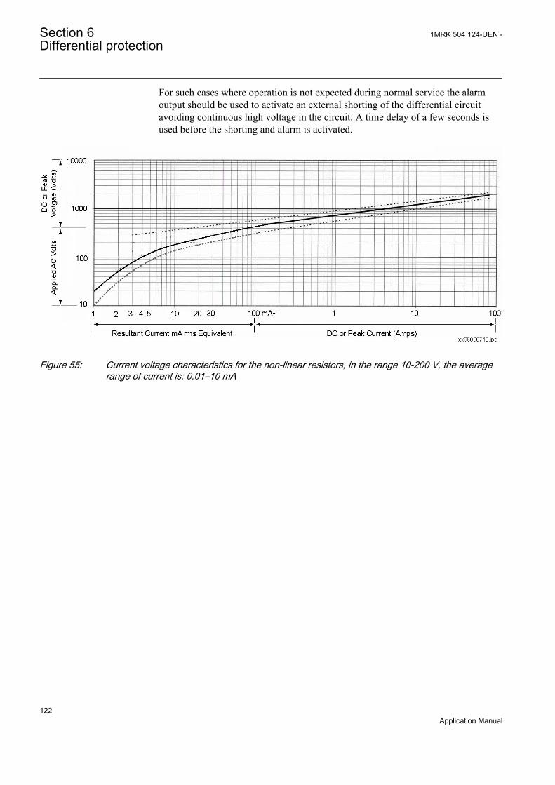
For such cases where operation is not expected during normal service the alarmoutput should be used to activate an external shorting of the differential circuitavoiding continuous high voltage in the circuit. A time delay of a few seconds isused before the shorting and alarm is activated.
IEC05000749 V1 EN
Figure 55: Current voltage characteristics for the non-linear resistors, in the range 10-200 V, the averagerange of current is: 0.01–10 mA
Section 6 1MRK 504 124-UEN -Differential protection
122Application Manual

Section 7 Current protection
7.1 Instantaneous phase overcurrent protection PHPIOC
7.1.1 IdentificationFunction description IEC 61850
identificationIEC 60617identification
ANSI/IEEE C37.2device number
Instantaneous phase overcurrentprotection
PHPIOC
3I>>
SYMBOL-Z V1 EN
50
7.1.2 ApplicationLong transmission lines often transfer great quantities of electric power fromproduction to consumption areas. The unbalance of the produced and consumedelectric power at each end of the transmission line is very large. This means that afault on the line can easily endanger the stability of a complete system.
The transient stability of a power system depends mostly on three parameters (atconstant amount of transmitted electric power):
• The type of the fault. Three-phase faults are the most dangerous, because nopower can be transmitted through the fault point during fault conditions.
• The magnitude of the fault current. A high fault current indicates that thedecrease of transmitted power is high.
• The total fault clearing time. The phase angles between the EMFs of thegenerators on both sides of the transmission line increase over the permittedstability limits if the total fault clearing time, which consists of the protectionoperating time and the breaker opening time, is too long.
The fault current on long transmission lines depends mostly on the fault positionand decreases with the distance from the generation point. For this reason theprotection must operate very quickly for faults very close to the generation (andrelay) point, for which very high fault currents are characteristic.
The instantaneous phase overcurrent protection PHPIOC can operate in 10 ms forfaults characterized by very high currents.
1MRK 504 124-UEN - Section 7Current protection
123Application Manual

7.1.3 Setting guidelinesThe parameters for instantaneous phase overcurrent protection PHPIOC are set viathe local HMI or PCM600.
This protection function must operate only in a selective way. So check all systemand transient conditions that could cause its unwanted operation.
Only detailed network studies can determine the operating conditions under whichthe highest possible fault current is expected on the line. In most cases, this currentappears during three-phase fault conditions. But also examine single-phase-to-earthand two-phase-to-earth conditions.
Also study transients that could cause a high increase of the line current for shorttimes. A typical example is a transmission line with a power transformer at theremote end, which can cause high inrush current when connected to the networkand can thus also cause the operation of the built-in, instantaneous, overcurrentprotection.
Common base IED values for primary current (IBase), primary voltage (UBase)and primary power (SBase) are set in a Global base values for settings functionGBASVAL. Setting GlobalBaseSel is used to select a GBASVAL function forreference of base values.
IP>>: Set operate current in % of IBase.
7.1.3.1 Meshed network without parallel line
The following fault calculations have to be done for three-phase, single-phase-to-earth and two-phase-to-earth faults. With reference to figure 56, apply a fault in Band then calculate the current through-fault phase current IfB. The calculationshould be done using the minimum source impedance values for ZA and themaximum source impedance values for ZB in order to get the maximum throughfault current from A to B.
Section 7 1MRK 504 124-UEN -Current protection
124Application Manual

~ ~ZA ZBZ L
A B
IED
I fB
Fault
IEC09000022-1-en.vsdIEC09000022 V1 EN
Figure 56: Through fault current from A to B: IfB
Then a fault in A has to be applied and the through fault current IfA has to becalculated, figure 57. In order to get the maximum through fault current, theminimum value for ZB and the maximum value for ZA have to be considered.
IEC09000023-1-en.vsd
~ ~ZA ZBZ L
A B
IED
I fA
Fault
IEC09000023 V1 EN
Figure 57: Through fault current from B to A: IfA
The IED must not trip for any of the two through-fault currents. Hence theminimum theoretical current setting (Imin) will be:
Imin MAX I fA IfB,( )³
EQUATION78 V1 EN (Equation 44)
A safety margin of 5% for the maximum protection static inaccuracy and a safetymargin of 5% for the maximum possible transient overreach have to be introduced.An additional 20% is suggested due to the inaccuracy of the instrumenttransformers under transient conditions and inaccuracy in the system data.
The minimum primary setting (Is) for the instantaneous phase overcurrentprotection is then:
1MRK 504 124-UEN - Section 7Current protection
125Application Manual

Is 1 3, Imin׳
EQUATION79 V1 EN (Equation 45)
The protection function can be used for the specific application only if this settingvalue is equal to or less than the maximum fault current that the IED has to clear, IFin figure 58.
IEC09000024-1-en.vsd
~ ~ZA ZBZ L
A B
IED
I F
Fault
IEC09000024 V1 EN
Figure 58: Fault current: IF
100Is
IPIBase
>>= ×
EQUATION1147 V3 EN (Equation 46)
7.1.3.2 Meshed network with parallel line
In case of parallel lines, the influence of the induced current from the parallel lineto the protected line has to be considered. One example is given in figure 59 wherethe two lines are connected to the same busbars. In this case the influence of theinduced fault current from the faulty line (line 1) to the healthy line (line 2) isconsidered together with the two through fault currents IfA and IfB mentionedpreviously. The maximal influence from the parallel line for the IED in figure 59will be with a fault at the C point with the C breaker open.
A fault in C has to be applied, and then the maximum current seen from the IED(IM ) on the healthy line (this applies for single-phase-to-earth and two-phase-to-earth faults) is calculated.
Section 7 1MRK 504 124-UEN -Current protection
126Application Manual
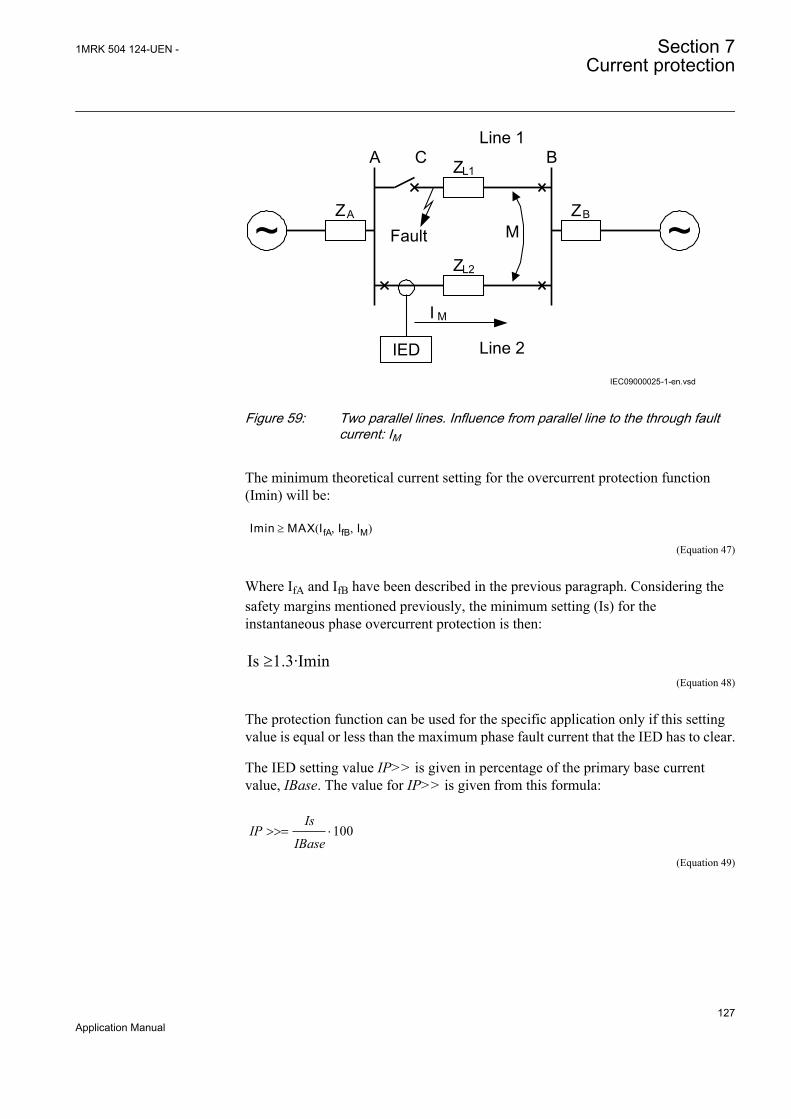
IEC09000025-1-en.vsd
~ ~ZA ZB
ZL1A B
I M
Fault
IED
ZL2
M
CLine 1
Line 2
IEC09000025 V1 EN
Figure 59: Two parallel lines. Influence from parallel line to the through faultcurrent: IM
The minimum theoretical current setting for the overcurrent protection function(Imin) will be:
Imin MAX I fA IfB IM, ,( )³
EQUATION82 V1 EN (Equation 47)
Where IfA and IfB have been described in the previous paragraph. Considering thesafety margins mentioned previously, the minimum setting (Is) for theinstantaneous phase overcurrent protection is then:
Is ³1.3·IminEQUATION83 V2 EN (Equation 48)
The protection function can be used for the specific application only if this settingvalue is equal or less than the maximum phase fault current that the IED has to clear.
The IED setting value IP>> is given in percentage of the primary base currentvalue, IBase. The value for IP>> is given from this formula:
100Is
IPIBase
>>= ×
EQUATION1147 V3 EN (Equation 49)
1MRK 504 124-UEN - Section 7Current protection
127Application Manual
7.2 Four step phase overcurrent protection OC4PTOC
7.2.1 IdentificationFunction description IEC 61850
identificationIEC 60617identification
ANSI/IEEE C37.2device number
Four step phase overcurrent protection OC4PTOC
44 alt
3I>
TOC-REVA V1 EN
51/67
7.2.2 ApplicationThe Four step phase overcurrent protection OC4PTOC is used in severalapplications in the power system. Some applications are:
• Short circuit protection of feeders in distribution and subtransmission systems.Normally these feeders have radial structure.
• Back-up short circuit protection of transmission lines.• Back-up short circuit protection of power transformers.• Short circuit protection of different kinds of equipment connected to the power
system such as; shunt capacitor banks, shunt reactors, motors and others.• Back-up short circuit protection of power generators.
If VT inputs are not available or not connected, setting parameterDirModex (x = step 1, 2, 3 or 4) shall be left to default value Non-directionalor set to Off.
In many applications several steps with different current pick up levels and timedelays are needed. OC4PTOC can have up to four different, individual settable,steps. The flexibility of each step of OC4PTOC is great. The following options arepossible:
Non-directional / Directional function: In most applications the non-directionalfunctionality is used. This is mostly the case when no fault current can be fed fromthe protected object itself. In order to achieve both selectivity and fast faultclearance, the directional function can be necessary.
Choice of delay time characteristics: There are several types of delay timecharacteristics available such as definite time delay and different types of inversetime delay characteristics. The selectivity between different overcurrent protectionsis normally enabled by co-ordination between the function time delays of thedifferent protections. To enable optimal co-ordination between all overcurrentprotections, they should have the same time delay characteristic. Therefore a widerange of standardized inverse time characteristics are available: IEC and ANSI.
Section 7 1MRK 504 124-UEN -Current protection
128Application Manual

The time characteristic for step 1 and 4 can be chosen as definite time delay orinverse time characteristic. Step 2 and 3 are always definite time delayed and areused in system where IDMT is not needed.
7.2.3 Setting guidelinesThe parameters for Four step phase overcurrent protection OC4PTOC are set viathe local HMI or PCM600.
The following settings can be done for OC4PTOC.
Common base IED values for primary current (IBase), primary voltage (UBase)and primary power (SBase) are set in a Global base values for settings functionGBASVAL. Setting GlobalBaseSel is used to select a GBASVAL function forreference of base values.
MeasType: Selection of discrete Fourier filtered (DFT) or true RMS filtered (RMS)signals. RMS is used when the harmonic contents are to be considered, for examplein applications with shunt capacitors.
Operation: The protection can be set to Off or On
1MRK 504 124-UEN - Section 7Current protection
129Application Manual
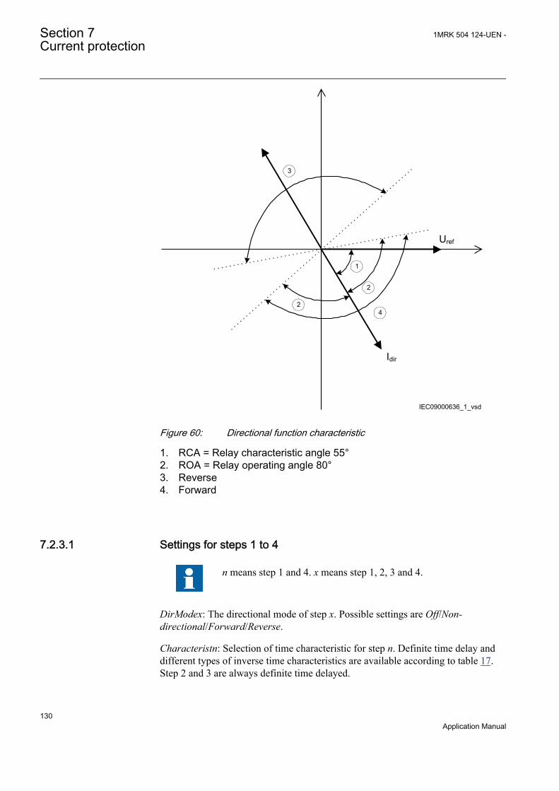
Uref
Idir
IEC09000636_1_vsd
1
2
2
3
4
IEC09000636 V1 EN
Figure 60: Directional function characteristic
1. RCA = Relay characteristic angle 55°2. ROA = Relay operating angle 80°3. Reverse4. Forward
7.2.3.1 Settings for steps 1 to 4
n means step 1 and 4. x means step 1, 2, 3 and 4.
DirModex: The directional mode of step x. Possible settings are Off/Non-directional/Forward/Reverse.
Characteristn: Selection of time characteristic for step n. Definite time delay anddifferent types of inverse time characteristics are available according to table 17.Step 2 and 3 are always definite time delayed.
Section 7 1MRK 504 124-UEN -Current protection
130Application Manual
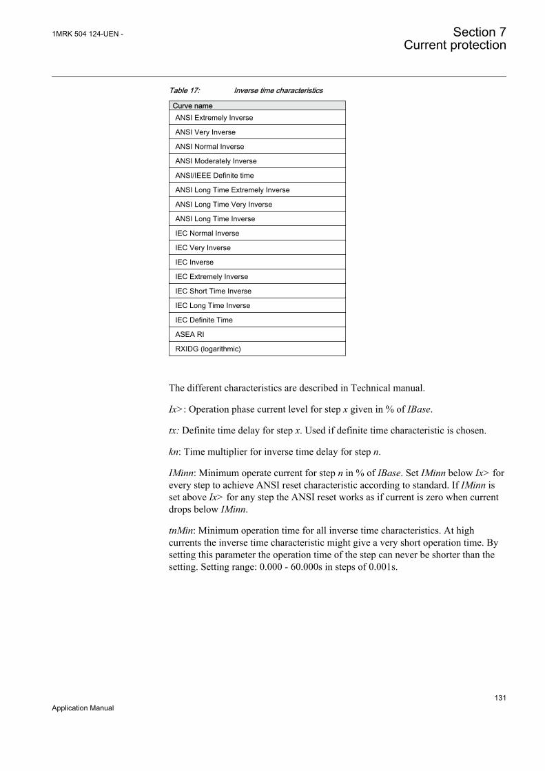
Table 17: Inverse time characteristics
Curve nameANSI Extremely Inverse
ANSI Very Inverse
ANSI Normal Inverse
ANSI Moderately Inverse
ANSI/IEEE Definite time
ANSI Long Time Extremely Inverse
ANSI Long Time Very Inverse
ANSI Long Time Inverse
IEC Normal Inverse
IEC Very Inverse
IEC Inverse
IEC Extremely Inverse
IEC Short Time Inverse
IEC Long Time Inverse
IEC Definite Time
ASEA RI
RXIDG (logarithmic)
The different characteristics are described in Technical manual.
Ix>: Operation phase current level for step x given in % of IBase.
tx: Definite time delay for step x. Used if definite time characteristic is chosen.
kn: Time multiplier for inverse time delay for step n.
IMinn: Minimum operate current for step n in % of IBase. Set IMinn below Ix> forevery step to achieve ANSI reset characteristic according to standard. If IMinn isset above Ix> for any step the ANSI reset works as if current is zero when currentdrops below IMinn.
tnMin: Minimum operation time for all inverse time characteristics. At highcurrents the inverse time characteristic might give a very short operation time. Bysetting this parameter the operation time of the step can never be shorter than thesetting. Setting range: 0.000 - 60.000s in steps of 0.001s.
1MRK 504 124-UEN - Section 7Current protection
131Application Manual
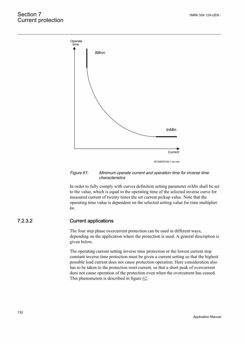
Current
Operatetime
IMinn
tnMin
IEC09000164-1-en.vsdIEC09000164 V1 EN
Figure 61: Minimum operate current and operation time for inverse timecharacteristics
In order to fully comply with curves definition setting parameter tnMin shall be setto the value, which is equal to the operating time of the selected inverse curve formeasured current of twenty times the set current pickup value. Note that theoperating time value is dependent on the selected setting value for time multiplierkn.
7.2.3.2 Current applications
The four step phase overcurrent protection can be used in different ways,depending on the application where the protection is used. A general description isgiven below.
The operating current setting inverse time protection or the lowest current stepconstant inverse time protection must be given a current setting so that the highestpossible load current does not cause protection operation. Here consideration alsohas to be taken to the protection reset current, so that a short peak of overcurrentdoes not cause operation of the protection even when the overcurrent has ceased.This phenomenon is described in figure 62.
Section 7 1MRK 504 124-UEN -Current protection
132Application Manual

Operating current
Current I
The IED does not reset
Line phase current
Time t
Reset current
IEC05000203-en-2.vsdIEC05000203 V2 EN
Figure 62: Operating and reset current for an overcurrent protection
The lowest setting value can be written according to equation 50.
ImaxIpu 1.2k
³ ×
EQUATION1262 V2 EN (Equation 50)
where:
1.2 is a safety factor,
k is the resetting ratio of the protection, and
Imax is the maximum load current.
The maximum load current on the line has to be estimated. There is also a demandthat all faults, within the zone that the protection shall cover, must be detected bythe phase overcurrent protection. The minimum fault current Iscmin, to be detectedby the protection, must be calculated. Taking this value as a base, the highest pickup current setting can be written according to equation 51.
1MRK 504 124-UEN - Section 7Current protection
133Application Manual
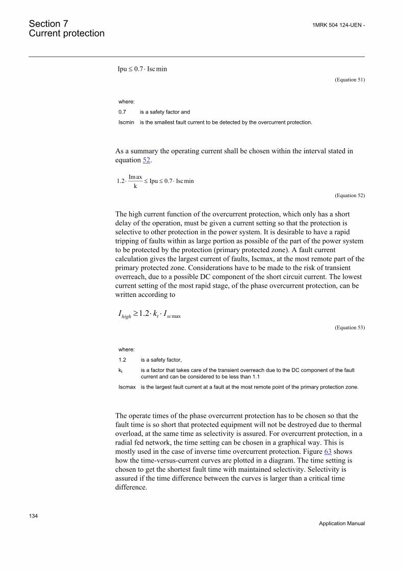
Ipu 0.7 Iscmin£ ×EQUATION1263 V2 EN (Equation 51)
where:
0.7 is a safety factor and
Iscmin is the smallest fault current to be detected by the overcurrent protection.
As a summary the operating current shall be chosen within the interval stated inequation 52.
Imax1.2 Ipu 0.7 Iscmink
× £ £ ×
EQUATION1264 V2 EN (Equation 52)
The high current function of the overcurrent protection, which only has a shortdelay of the operation, must be given a current setting so that the protection isselective to other protection in the power system. It is desirable to have a rapidtripping of faults within as large portion as possible of the part of the power systemto be protected by the protection (primary protected zone). A fault currentcalculation gives the largest current of faults, Iscmax, at the most remote part of theprimary protected zone. Considerations have to be made to the risk of transientoverreach, due to a possible DC component of the short circuit current. The lowestcurrent setting of the most rapid stage, of the phase overcurrent protection, can bewritten according to
max1.2 t schighI k I³ × ×
EQUATION1265 V1 EN (Equation 53)
where:
1.2 is a safety factor,
kt is a factor that takes care of the transient overreach due to the DC component of the faultcurrent and can be considered to be less than 1.1
Iscmax is the largest fault current at a fault at the most remote point of the primary protection zone.
The operate times of the phase overcurrent protection has to be chosen so that thefault time is so short that protected equipment will not be destroyed due to thermaloverload, at the same time as selectivity is assured. For overcurrent protection, in aradial fed network, the time setting can be chosen in a graphical way. This ismostly used in the case of inverse time overcurrent protection. Figure 63 showshow the time-versus-current curves are plotted in a diagram. The time setting ischosen to get the shortest fault time with maintained selectivity. Selectivity isassured if the time difference between the curves is larger than a critical timedifference.
Section 7 1MRK 504 124-UEN -Current protection
134Application Manual

en05000204.wmfIEC05000204 V1 EN
Figure 63: Fault time with maintained selectivity
To assure selectivity between different protections, in the radial network, therehave to be a minimum time difference Dt between the time delays of twoprotections. The minimum time difference can be determined for different cases.To determine the shortest possible time difference, the operation time ofprotections, breaker opening time and protection resetting time must be known.These time delays can vary significantly between different protective equipment.The following time delays can be estimated:
Protection operationtime:
15-60 ms
Protection resetting time: 15-60 ms
Breaker opening time: 20-120 ms
ExampleAssume two substations A and B directly connected to each other via one line, asshown in the figure 64. Consider a fault located at another line from the station B.The fault current to the overcurrent protection of IED B1 has a magnitude so thatthe protection will have instantaneous function. The overcurrent protection of IEDA1 must have a delayed function. The sequence of events during the fault can bedescribed using a time axis, see figure 64.
1MRK 504 124-UEN - Section 7Current protection
135Application Manual

I> I>
A1 B1 Feeder
Time axis
t=0 t=t1 t=t2 t=t3The faultoccurs
ProtectionB1 trips
Breaker atB1 opens
ProtectionA1 resets
en05000205.vsd
IEC05000205 V1 EN
Figure 64: Sequence of events during fault
where:
t=0 is when the fault occurs,
t=t1 is when the trip signal from the overcurrent protection at IED B1 is sent to the circuit breaker.The operation time of this protection is t1,
t=t2 is when the circuit breaker at IED B1 opens. The circuit breaker opening time is t2 - t1 and
t=t3 is when the overcurrent protection at IED A1 resets. The protection resetting time is t3 - t2.
To ensure that the overcurrent protection at IED A1, is selective to the overcurrentprotection at IED B1, the minimum time difference must be larger than the time t3.There are uncertainties in the values of protection operation time, breaker openingtime and protection resetting time. Therefore a safety margin has to be included.With normal values the needed time difference can be calculated according toequation 54.
40 100 40 40 220t ms ms ms ms msD ³ + + + =EQUATION1266 V1 EN (Equation 54)
where it is considered that:
the operation time of overcurrent protection B1 is 40 ms
the breaker open time is 100 ms
the resetting time of protection A1 is 40 ms and
the additional margin is 40 ms
Section 7 1MRK 504 124-UEN -Current protection
136Application Manual

7.3 Instantaneous residual overcurrent protectionEFPIOC
7.3.1 IdentificationFunction description IEC 61850
identificationIEC 60617identification
ANSI/IEEE C37.2device number
Instantaneous residual overcurrentprotection
EFPIOC
IN>>
IEF V1 EN
50N
7.3.2 ApplicationIn many applications, when fault current is limited to a defined value by the objectimpedance, an instantaneous earth-fault protection can provide fast and selectivetripping.
The Instantaneous residual overcurrent EFPIOC, which can operate in 15 ms (50Hz nominal system frequency) for faults characterized by very high currents, isincluded in the IED.
7.3.3 Setting guidelinesThe parameters for the Instantaneous residual overcurrent protection EFPIOC areset via the local HMI or PCM600.
Some guidelines for the choice of setting parameter for EFPIOC is given.
Common base IED values for primary current (IBase), primary voltage (UBase)and primary power (SBase) are set in a Global base values for settings functionGBASVAL. Setting GlobalBaseSel is used to select a GBASVAL function forreference of base values.
The setting of the function is limited to the operation residual current to theprotection (IN>>).
The basic requirement is to assure selectivity, that is EFPIOC shall not be allowedto operate for faults at other objects than the protected object (line).
For a normal line in a meshed system single phase-to-earth faults and phase-to-phase-to-earth faults shall be calculated as shown in figure 65 and figure 66. The residualcurrents (3I0) to the protection are calculated. For a fault at the remote line end thisfault current is IfB. In this calculation the operational state with high sourceimpedance ZA and low source impedance ZB should be used. For the fault at the
1MRK 504 124-UEN - Section 7Current protection
137Application Manual

home busbar this fault current is IfA. In this calculation the operational state withlow source impedance ZA and high source impedance ZB should be used.
~ ~ZA ZBZ L
A B
IED
I fB
Fault
IEC09000022-1-en.vsd
IEC09000022 V1 EN
Figure 65: Through fault current from A to B: IfB
IEC09000023-1-en.vsd
~ ~ZA ZBZ L
A B
IED
I fA
Fault
IEC09000023 V1 EN
Figure 66: Through fault current from B to A: IfA
The function shall not operate for any of the calculated currents to the protection.The minimum theoretical current setting (Imin) will be:
Imin MAX IfA IfA,( )³
EQUATION284 V1 EN (Equation 55)
A safety margin of 5% for the maximum static inaccuracy and a safety margin of5% for maximum possible transient overreach have to be introduced. An additional20% is suggested due to inaccuracy of instrument transformers under transientconditions and inaccuracy in the system data.
The minimum primary current setting (Is) is:
Is 1 3, Imin׳EQUATION285 V1 EN (Equation 56)
Section 7 1MRK 504 124-UEN -Current protection
138Application Manual

In case of parallel lines with zero sequence mutual coupling a fault on the parallelline, as shown in figure 67, should be calculated.
IEC09000025-1-en.vsd
~ ~ZA ZB
ZL1A B
I M
Fault
IED
ZL2
M
CLine 1
Line 2
IEC09000025 V1 EN
Figure 67: Two parallel lines. Influence from parallel line to the through faultcurrent: IM
The minimum theoretical current setting (Imin) will in this case be:
I m in M AX IfA I fB IM, ,( )³
EQUATION287 V1 EN (Equation 57)
Where:
IfA and IfB have been described for the single line case.
Considering the safety margins mentioned previously, the minimum setting (Is) is:
Is 1 3, Imin׳
EQUATION288 V1 EN (Equation 58)
Transformer inrush current shall be considered.
The setting of the protection is set as a percentage of the base current (IBase).
Operation: set the protection to On or Off.
IN>>: Set operate current in % of IBase. IBase is a global parameter valid for allfunctions in the IED.
1MRK 504 124-UEN - Section 7Current protection
139Application Manual
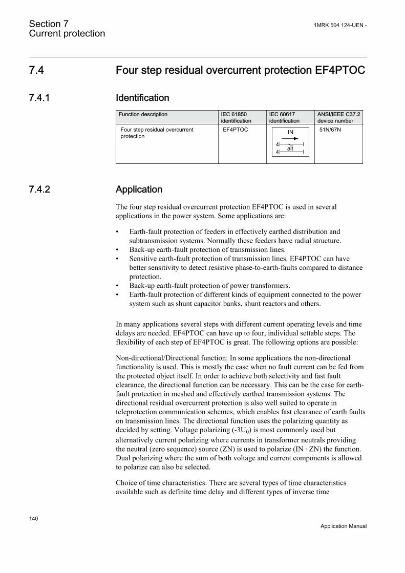
7.4 Four step residual overcurrent protection EF4PTOC
7.4.1 IdentificationFunction description IEC 61850
identificationIEC 60617identification
ANSI/IEEE C37.2device number
Four step residual overcurrentprotection
EF4PTOC
44 alt
IN
TEF-REVA V1 EN
51N/67N
7.4.2 ApplicationThe four step residual overcurrent protection EF4PTOC is used in severalapplications in the power system. Some applications are:
• Earth-fault protection of feeders in effectively earthed distribution andsubtransmission systems. Normally these feeders have radial structure.
• Back-up earth-fault protection of transmission lines.• Sensitive earth-fault protection of transmission lines. EF4PTOC can have
better sensitivity to detect resistive phase-to-earth-faults compared to distanceprotection.
• Back-up earth-fault protection of power transformers.• Earth-fault protection of different kinds of equipment connected to the power
system such as shunt capacitor banks, shunt reactors and others.
In many applications several steps with different current operating levels and timedelays are needed. EF4PTOC can have up to four, individual settable steps. Theflexibility of each step of EF4PTOC is great. The following options are possible:
Non-directional/Directional function: In some applications the non-directionalfunctionality is used. This is mostly the case when no fault current can be fed fromthe protected object itself. In order to achieve both selectivity and fast faultclearance, the directional function can be necessary. This can be the case for earth-fault protection in meshed and effectively earthed transmission systems. Thedirectional residual overcurrent protection is also well suited to operate inteleprotection communication schemes, which enables fast clearance of earth faultson transmission lines. The directional function uses the polarizing quantity asdecided by setting. Voltage polarizing (-3U0) is most commonly used butalternatively current polarizing where currents in transformer neutrals providingthe neutral (zero sequence) source (ZN) is used to polarize (IN · ZN) the function.Dual polarizing where the sum of both voltage and current components is allowedto polarize can also be selected.
Choice of time characteristics: There are several types of time characteristicsavailable such as definite time delay and different types of inverse time
Section 7 1MRK 504 124-UEN -Current protection
140Application Manual

characteristics. The selectivity between different overcurrent protections isnormally enabled by co-ordination between the operating time of the differentprotections. To enable optimal co-ordination all overcurrent protections, to be co-ordinated against each other, should have the same time characteristic. Therefore awide range of standardized inverse time characteristics are available: IEC andANSI. The time characteristic for step 1 and 4 can be chosen as definite time delayor inverse time characteristic. Step 2 and 3 are always definite time delayed and areused in system where IDMT is not needed.
Table 18: Time characteristics
Curve nameANSI Extremely Inverse
ANSI Very Inverse
ANSI Normal Inverse
ANSI Moderately Inverse
ANSI/IEEE Definite time
ANSI Long Time Extremely Inverse
ANSI Long Time Very Inverse
ANSI Long Time Inverse
IEC Normal Inverse
IEC Very Inverse
IEC Inverse
IEC Extremely Inverse
IEC Short Time Inverse
IEC Long Time Inverse
IEC Definite Time
ASEA RI
RXIDG (logarithmic)
Power transformers can have a large inrush current, when being energized. Thisinrush current can have residual current components. The phenomenon is due tosaturation of the transformer magnetic core during parts of the cycle. There is a riskthat inrush current will give a residual current that reaches level above theoperating current of the residual overcurrent protection. The inrush current has alarge second harmonic content. This can be used to avoid unwanted operation ofthe protection. Therefore, EF4PTOC has a possibility of second harmonic restrain2ndHarmStab if the level of this harmonic current reaches a value above a setpercentage of the fundamental current.
7.4.3 Setting guidelinesThe parameters for the four step residual overcurrent protection EF4PTOC are setvia the local HMI or PCM600.
1MRK 504 124-UEN - Section 7Current protection
141Application Manual
The following settings can be done for the four step residual overcurrent protection.
Common base IED values for primary current (IBase), primary voltage (UBase)and primary power (SBase) are set in a Global base values for settings functionGBASVAL. Setting GlobalBaseSel is used to select a GBASVAL function forreference of base values.
Operation: Sets the protection to On or Off.
7.4.3.1 Settings for steps 1 and 4
n means step 1 and 4.
DirModex: The directional mode of step x. Possible settings are Off/Non-directional/Forward/Reverse.
Characteristx: Selection of time characteristic for step x. Definite time delay anddifferent types of inverse time characteristics are available.
Inverse time characteristic enables fast fault clearance of high current faults at thesame time as selectivity to other inverse time phase overcurrent protections can beassured. This is mainly used in radial fed networks but can also be used in meshednetworks. In meshed networks the settings must be based on network faultcalculations.
To assure selectivity between different protections, in the radial network, therehave to be a minimum time difference Dt between the time delays of twoprotections. The minimum time difference can be determined for different cases.To determine the shortest possible time difference, the operation time ofprotections, breaker opening time and protection resetting time must be known.These time delays can vary significantly between different protective equipment.The following time delays can be estimated:
Protection operation time: 15-60 ms
Protection resetting time: 15-60 ms
Breaker opening time: 20-120 ms
The different characteristics are described in the Technical Manual (TM).
INx>: Operation residual current level for step x given in % of IBase.
kx: Time multiplier for the dependent (inverse) characteristic for step x.
IMinn: Minimum operate current for step n in % of IBase. Set IMinn below Ix> forevery step to achieve ANSI reset characteristic according to standard. If IMinn isset above Ix> for any step the ANSI reset works as if current is zero when currentdrops below IMinn.
Section 7 1MRK 504 124-UEN -Current protection
142Application Manual
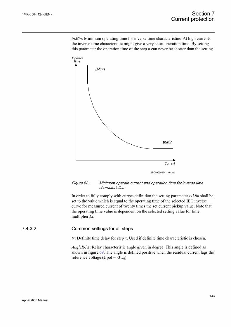
tnMin: Minimum operating time for inverse time characteristics. At high currentsthe inverse time characteristic might give a very short operation time. By settingthis parameter the operation time of the step n can never be shorter than the setting.
Current
Operatetime
IMinn
tnMin
IEC09000164-1-en.vsdIEC09000164 V1 EN
Figure 68: Minimum operate current and operation time for inverse timecharacteristics
In order to fully comply with curves definition the setting parameter txMin shall beset to the value which is equal to the operating time of the selected IEC inversecurve for measured current of twenty times the set current pickup value. Note thatthe operating time value is dependent on the selected setting value for timemultiplier kx.
7.4.3.2 Common settings for all steps
tx: Definite time delay for step x. Used if definite time characteristic is chosen.
AngleRCA: Relay characteristic angle given in degree. This angle is defined asshown in figure 69. The angle is defined positive when the residual current lags thereference voltage (Upol = -3U0)
1MRK 504 124-UEN - Section 7Current protection
143Application Manual
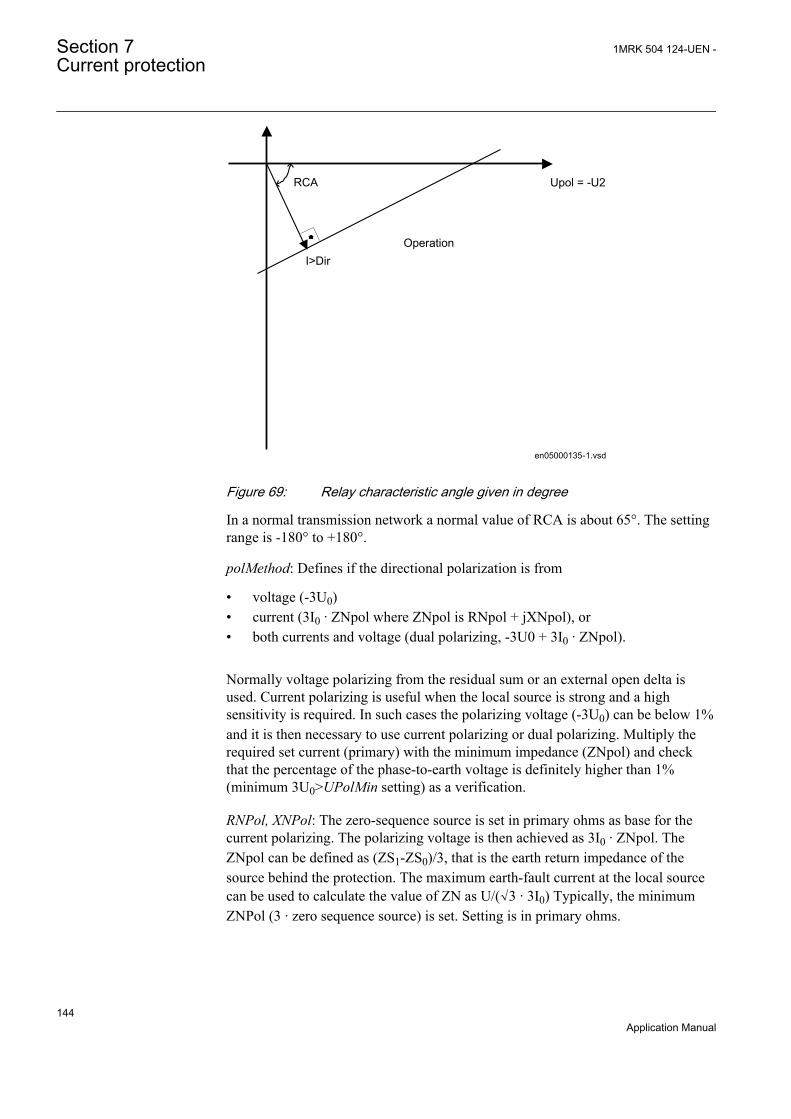
en05000135-1.vsd
Upol = -U2
I>Dir
RCA
Operation
IEC05000135 V2 EN
Figure 69: Relay characteristic angle given in degree
In a normal transmission network a normal value of RCA is about 65°. The settingrange is -180° to +180°.
polMethod: Defines if the directional polarization is from
• voltage (-3U0)• current (3I0 · ZNpol where ZNpol is RNpol + jXNpol), or• both currents and voltage (dual polarizing, -3U0 + 3I0 · ZNpol).
Normally voltage polarizing from the residual sum or an external open delta isused. Current polarizing is useful when the local source is strong and a highsensitivity is required. In such cases the polarizing voltage (-3U0) can be below 1%and it is then necessary to use current polarizing or dual polarizing. Multiply therequired set current (primary) with the minimum impedance (ZNpol) and checkthat the percentage of the phase-to-earth voltage is definitely higher than 1%(minimum 3U0>UPolMin setting) as a verification.
RNPol, XNPol: The zero-sequence source is set in primary ohms as base for thecurrent polarizing. The polarizing voltage is then achieved as 3I0 · ZNpol. TheZNpol can be defined as (ZS1-ZS0)/3, that is the earth return impedance of thesource behind the protection. The maximum earth-fault current at the local sourcecan be used to calculate the value of ZN as U/(√3 · 3I0) Typically, the minimumZNPol (3 · zero sequence source) is set. Setting is in primary ohms.
Section 7 1MRK 504 124-UEN -Current protection
144Application Manual
When the dual polarizing method is used it is important that the setting INx> or theproduct 3I0 · ZNpol is not greater than 3U0. If so, there is a risk for incorrectoperation for faults in the reverse direction.
IPolMin: is the minimum earth-fault current accepted for directional evaluation.For smaller currents than this value the operation will be blocked. Typical setting is5-10% of IBase.
UPolMin: Minimum polarization (reference) residual voltage for the directionalfunction, given in % of UBase/√3.
IN>Dir: Operating residual current release level in % of IBase for directionalcomparison scheme. The setting is given in % of IBase. The output signals, STFWand STRV can be used in a teleprotection scheme. The appropriate signal should beconfigured to the communication scheme block.
7.4.3.3 2nd harmonic restrain
If a power transformer is energized there is a risk that the current transformer corewill saturate during part of the period, resulting in an inrush transformer current.This will give a declining residual current in the network, as the inrush current isdeviating between the phases. There is a risk that the residual overcurrent functionwill give an unwanted trip. The inrush current has a relatively large ratio of 2ndharmonic component. This component can be used to create a restrain signal toprevent this unwanted function.
At current transformer saturation a false residual current can be measured by theprotection. Also here the 2nd harmonic restrain can prevent unwanted operation.
2ndHarmStab: The rate of 2nd harmonic current content for activation of the 2ndharmonic restrain signal. The setting is given in % of the fundamental frequencyresidual current.
HarmRestrainx: Enable block of step x from the harmonic restrain function.
7.4.3.4 Transformer application example
Two main cases are of interest when residual overcurrent protection is used for apower transformer, namely if residual current can be fed from the protectedtransformer winding or not.
The protected winding will feed earth-fault (residual) current to earth faults in theconnected power system. The residual current fed from the transformer at externalphase-to-earth faults, is highly dependent of the total positive and zero-sequencesource impedances as well as the residual current distribution between the networkzero-sequence impedance and the transformer zero-sequence impedance. Anexample of this application is shown in figure 70.
1MRK 504 124-UEN - Section 7Current protection
145Application Manual
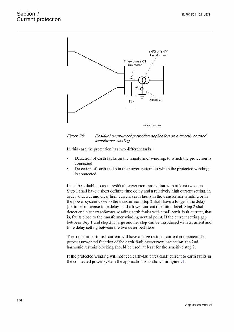
IN>
alt
Three phase CTsummated
Single CT
YN/D or YN/Ytransformer
en05000490.vsdIEC05000490 V1 EN
Figure 70: Residual overcurrent protection application on a directly earthedtransformer winding
In this case the protection has two different tasks:
• Detection of earth faults on the transformer winding, to which the protection isconnected.
• Detection of earth faults in the power system, to which the protected windingis connected.
It can be suitable to use a residual overcurrent protection with at least two steps.Step 1 shall have a short definite time delay and a relatively high current setting, inorder to detect and clear high current earth faults in the transformer winding or inthe power system close to the transformer. Step 2 shall have a longer time delay(definite or inverse time delay) and a lower current operation level. Step 2 shalldetect and clear transformer winding earth faults with small earth-fault current, thatis, faults close to the transformer winding neutral point. If the current setting gapbetween step 1 and step 2 is large another step can be introduced with a current andtime delay setting between the two described steps.
The transformer inrush current will have a large residual current component. Toprevent unwanted function of the earth-fault overcurrent protection, the 2ndharmonic restrain blocking should be used, at least for the sensitive step 2.
If the protected winding will not feed earth-fault (residual) current to earth faults inthe connected power system the application is as shown in figure 71.
Section 7 1MRK 504 124-UEN -Current protection
146Application Manual

IN>
Three phase CTsummated
Y/Y, Y/D or D/Ytransformer
en05000491.vsdIEC05000491 V1 EN
Figure 71: Residual overcurrent protection application on an isolatedtransformer winding
In the calculation of the fault current fed to the protection, at different earth faults,are highly dependent on the positive and zero sequence source impedances, as wellas the division of residual current in the network. Earth-fault current calculationsare necessary for the setting.
Setting of step 1One requirement is that earth faults at the busbar, where the transformer winding isconnected, shall be detected. Therefore a fault calculation as shown in figure 72 ismade.
1MRK 504 124-UEN - Section 7Current protection
147Application Manual

IN>
alt
Three phase CTsummated
Single CT
YN/D or YN/Ytransformer
Single phase-to-earth fault
3I0
IEC05000492-en-2.vsdIEC05000492 V2 EN
Figure 72: Step 1 fault calculation 1
This calculation gives the current fed to the protection: 3I0fault1.
To assure that step 1, selectivity to other earth-fault protections in the network ashort delay is selected. Normally, a delay in the range 0.3 – 0.4 s is appropriate. Toassure selectivity to line faults, tripped after a delay (typically distance protectionzone 2) of about 0.5 s the current setting must be set so high so that such faultsdoes not cause unwanted step 1 trip. Therefore, a fault calculation as shown infigure 73 is made.
IN>
alt
Three phase CTsummated
Single CT
YN/D or YN/Ytransformer
Single phase-to-earth fault
3I0
IEC05000493-en-2.vsd
IEC05000493 V2 EN
Figure 73: Step 1 fault calculation 1
Section 7 1MRK 504 124-UEN -Current protection
148Application Manual
The fault is located at the borderline between instantaneous and delayed operationof the line protection, such as Distance protection or line residual overcurrentprotection. This calculation gives the current fed to the protection: 3I0fault2
The setting of step 1 can be chosen within the interval shown in equation 59.
0fault 2 step1 0fault13I lowmar I 3I highmar× < < ×
EQUATION1455 V2 EN (Equation 59)
Where:
lowmar is a margin to assure selectivity (typical 1.2) and
highmar is a margin to assure fast fault clearance of busbar fault (typical 1.2).
Setting of step 2The setting of the sensitive step 2 is dependent of the chosen time delay. Often arelatively long definite time delay or inverse time delay is chosen. The currentsetting can be chosen very low. As it is required to detect earth faults in thetransformer winding, close to the neutral point, values down to the minimumsetting possibilities can be chosen. However, one must consider zero-sequencecurrents that can occur during normal operation of the power system. Such currentscan be due to un-transposed lines.
In case to protection of transformer windings not feeding residual current atexternal earth faults a fast lowcurrent step can be acceptable.
7.5 Thermal overload protection, two time constantsTRPTTR
7.5.1 IdentificationFunction description IEC 61850
identificationIEC 60617identification
ANSI/IEEE C37.2device number
Thermal overload protection, two timeconstants
TRPTTR
SYMBOL-A V1 EN
49
7.5.2 ApplicationTransformers in the power system are designed for a certain maximum load current(power) level. If the current exceeds this level the losses will be higher thanexpected. As a consequence the temperature of the transformer will increase. If the
1MRK 504 124-UEN - Section 7Current protection
149Application Manual

temperature of the transformer reaches too high values the equipment might bedamaged:
• The insulation within the transformer will have forced ageing. As aconsequence of this, the risk of internal phase-to-phase or phase-to-earth faultswill increase.
• There might be hot spots within the transformer, which will degrade the paperinsulation. It might also cause bubbling in the transformer oil.
In stressed situations in the power system it can be required to overloadtransformers for a limited time. This should be done without the above mentionedrisks. The thermal overload protection provides information and makes temporaryoverloading of transformers possible.
The permissible load level of a power transformer is highly dependent on thecooling system of the transformer. There are two main principles:
• ONAN: The air is naturally circulated to the coolers without fans and the oil isnaturally circulated without pumps.
• OFAF: The coolers have fans to force air for cooling and pumps to force thecirculation of the transformer oil.
The protection can have two sets of parameters, one for non-forced cooling and onefor forced cooling. Both the permissive steady state loading level as well as thethermal time constant is influenced by the cooling system of the transformer. Thetwo parameters sets can be activated by the binary input signal COOLING. Thiscan be used for transformers where forced cooling can be taken out of operation,for example at fan or pump faults.
The thermal overload protection estimates the internal heat content of thetransformer (temperature) continuously. This estimation is made by using a thermalmodel of the transformer, which is based on current measurement.
If the heat content of the protected transformer reaches a set alarm level a signalcan be given to the operator. Two alarm levels are available. This enablespreventive actions in the power system to be taken before dangerous temperaturesare reached. If the temperature continues to increase to the trip value, the protectioninitiates a trip of the protected transformer.
After tripping from the thermal overload protection, the transformer will cooldown. There will be a time gap before the heat content (temperature) reaches sucha level so that the transformer can be taken into service again. Therefore, thefunction will continue to estimate the heat content using a set cooling timeconstant. Energizing of the transformer can be blocked until the heat content hasreached to a set level.
Section 7 1MRK 504 124-UEN -Current protection
150Application Manual
7.5.3 Setting guidelineThe parameters for the thermal overload protection, two time constants (TRPTTR)are set via the local HMI or Protection and Control IED Manager (PCM600).
The following settings can be done for the thermal overload protection.
Common base IED values for primary current (IBase), primary voltage (UBase)and primary power (SBase) are set in a Global base values for settings functionGBASVAL. Setting GlobalBaseSel is used to select a GBASVAL function forreference of base values.
Operation: Off/On
IRef: Reference level of the current given in % of IBase. When the current is equalto IRef the final (steady state) heat content is equal to 1. It is suggested to give asetting corresponding to the rated current of the transformer winding.
IBase1: Base current for setting given as percentage of IBase. This setting shall berelated to the status no COOLING input. It is suggested to give a settingcorresponding to the rated current of the transformer with natural cooling (ONAN).
IBase2: Base current for setting given as percentage of IBase. This setting shall berelated to the status with activated COOLING input. It is suggested to give asetting corresponding to the rated current of the transformer with forced cooling(OFAF). If the transformer has no forced cooling IBase2 can be set equal to IBase1.
Tau1: The thermal time constant of the protected transformer, related to IBase1 (nocooling) given in minutes.
Tau2: The thermal time constant of the protected transformer, related to IBase2(with cooling) given in minutes.
The thermal time constant should be obtained from the transformer manufacturersmanuals. The thermal time constant is dependent on the cooling and the amount ofoil. Normal time constants for medium and large transformers (according to IEC60076-7) are about 2.5 hours for naturally cooled transformers and 1.5 hours forforced cooled transformers.
The time constant can be estimated from measurements of the oil temperatureduring a cooling sequence (described in IEC 60076-7). It is assumed that thetransformer is operated at a certain load level with a constant oil temperature(steady state operation). The oil temperature above the ambient temperature isDQo0. Then the transformer is disconnected from the grid (no load). After a time tof at least 30 minutes the temperature of the oil is measured again. Now the oiltemperature above the ambient temperature is DQot. The thermal time constant cannow be estimated as:
1MRK 504 124-UEN - Section 7Current protection
151Application Manual
0ln lno ot
tt =DQ - DQ
EQUATION1180 V1 EN (Equation 60)
If the transformer has forced cooling (OFAF) the measurement should be madeboth with and without the forced cooling in operation, giving Tau2 and Tau1.
The time constants can be changed if the current is higher than a set value or lowerthan a set value. If the current is high it is assumed that the forced cooling isactivated while it is deactivated at low current. The setting of the parameters belowenables automatic adjustment of the time constant.
Tau1High: Multiplication factor to adjust the time constant Tau1 if the current ishigher than the set value IHighTau1. IHighTau1 is set in % of IBase1.
Tau1Low: Multiplication factor to adjust the time constant Tau1 if the current islower than the set value ILowTau1. ILowTau1 is set in % of IBase1.
Tau2High: Multiplication factor to adjust the time constant Tau2 if the current ishigher than the set value IHighTau2. IHighTau2 is set in % of IBase2.
Tau2Low: Multiplication factor to adjust the time constant Tau2 if the current islower than the set value ILowTau2. ILowTau2 is set in % of IBase2.
The possibility to change time constant with the current value as the base can beuseful in different applications. Below some examples are given:
• In case a total interruption (low current) of the protected transformer allcooling possibilities will be inactive. This can result in a changed value of thetime constant.
• If other components (motors) are included in the thermal protection, there is arisk of overheating of that equipment in case of very high current. The thermaltime constant is often smaller for a motor than for the transformer.
ITrip: The steady state current that the transformer can withstand. The setting isgiven in % of IBase1 or IBase2.
Alarm1: Heat content level for activation of the signal ALARM1. ALARM1 is setin % of the trip heat content level.
Alarm2: Heat content level for activation of the output signal ALARM2. ALARM2is set in % of the trip heat content level.
ResLo: Lockout release level of heat content to release the lockout signal. Whenthe thermal overload protection trips a lock-out signal is activated. This signal isintended to block switch in of the protected circuit transformer as long as thetransformer temperature is high. The signal is released when the estimated heatcontent is below the set value. This temperature value should be chosen below thealarm temperature. ResLo is set in % of the trip heat content level.
Section 7 1MRK 504 124-UEN -Current protection
152Application Manual
Warning: If the calculated time to trip factor is below the setting Warning awarning signal is activated. The setting is given in minutes.
7.6 Breaker failure protection CCRBRF
7.6.1 IdentificationFunction description IEC 61850
identificationIEC 60617identification
ANSI/IEEE C37.2device number
Breaker failure protection CCRBRF
3I>BF
SYMBOL-U V1 EN
50BF
7.6.2 ApplicationIn the design of the fault clearance system the N-1 criterion is often used. Thismeans that a fault needs to be cleared even if any component in the fault clearancesystem is faulty. One necessary component in the fault clearance system is thecircuit breaker. It is from practical and economical reason not feasible to duplicatethe circuit breaker for the protected component. Instead a breaker failure protectionis used.
Breaker failure protection (CCRBRF) will issue a back-up trip command toadjacent circuit breakers in case of failure to trip of the “normal” circuit breaker forthe protected component. The detection of failure to break the current through thebreaker is made by means of current measurement or as detection of remaining tripsignal (unconditional).
CCRBRF can also give a re-trip. This means that a second trip signal is sent to theprotected circuit breaker. The re-trip function can be used to increase theprobability of operation of the breaker, or it can be used to avoid back-up trip ofmany breakers in case of mistakes during relay maintenance and test.
7.6.3 Setting guidelinesThe parameters for Breaker failure protection CCRBRF are set via the local HMIor PCM600.
The following settings can be done for the breaker failure protection.
Common base IED values for primary current (IBase), primary voltage (UBase)and primary power (SBase) are set in a Global base values for settings functionGBASVAL. Setting GlobalBaseSel is used to select a GBASVAL function forreference of base values.
1MRK 504 124-UEN - Section 7Current protection
153Application Manual
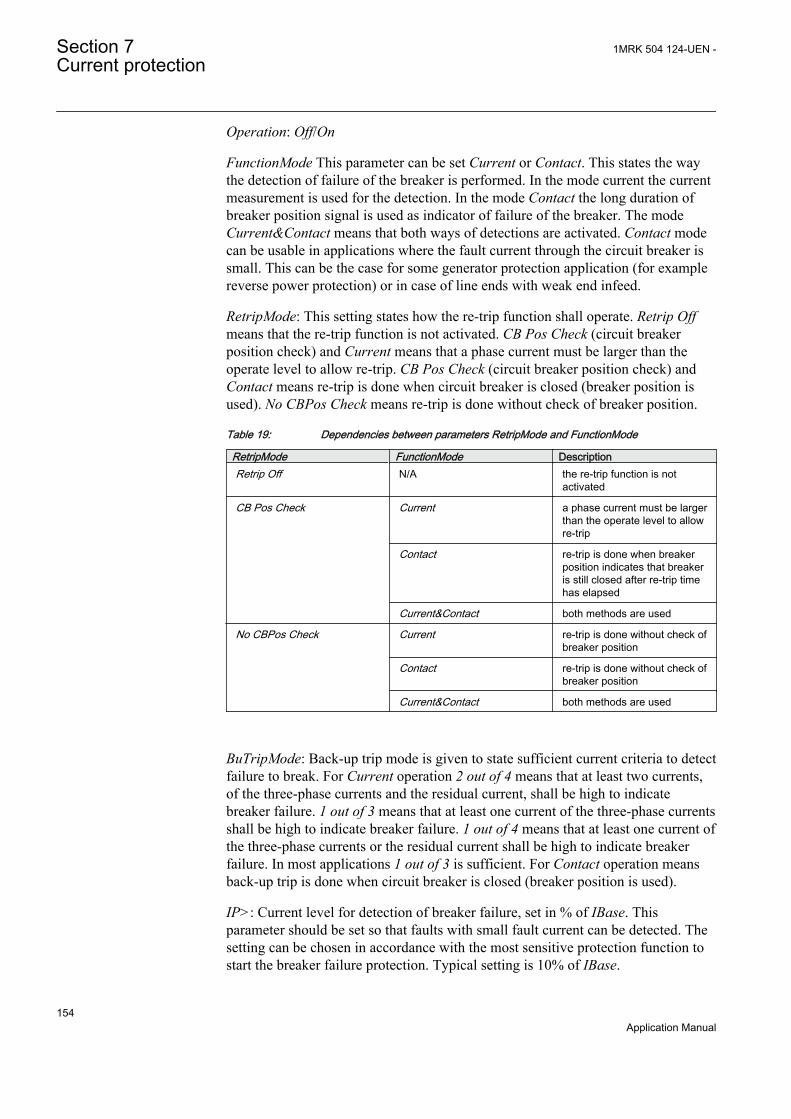
Operation: Off/On
FunctionMode This parameter can be set Current or Contact. This states the waythe detection of failure of the breaker is performed. In the mode current the currentmeasurement is used for the detection. In the mode Contact the long duration ofbreaker position signal is used as indicator of failure of the breaker. The modeCurrent&Contact means that both ways of detections are activated. Contact modecan be usable in applications where the fault current through the circuit breaker issmall. This can be the case for some generator protection application (for examplereverse power protection) or in case of line ends with weak end infeed.
RetripMode: This setting states how the re-trip function shall operate. Retrip Offmeans that the re-trip function is not activated. CB Pos Check (circuit breakerposition check) and Current means that a phase current must be larger than theoperate level to allow re-trip. CB Pos Check (circuit breaker position check) andContact means re-trip is done when circuit breaker is closed (breaker position isused). No CBPos Check means re-trip is done without check of breaker position.
Table 19: Dependencies between parameters RetripMode and FunctionMode
RetripMode FunctionMode DescriptionRetrip Off N/A the re-trip function is not
activated
CB Pos Check Current a phase current must be largerthan the operate level to allowre-trip
Contact re-trip is done when breakerposition indicates that breakeris still closed after re-trip timehas elapsed
Current&Contact both methods are used
No CBPos Check Current re-trip is done without check ofbreaker position
Contact re-trip is done without check ofbreaker position
Current&Contact both methods are used
BuTripMode: Back-up trip mode is given to state sufficient current criteria to detectfailure to break. For Current operation 2 out of 4 means that at least two currents,of the three-phase currents and the residual current, shall be high to indicatebreaker failure. 1 out of 3 means that at least one current of the three-phase currentsshall be high to indicate breaker failure. 1 out of 4 means that at least one current ofthe three-phase currents or the residual current shall be high to indicate breakerfailure. In most applications 1 out of 3 is sufficient. For Contact operation meansback-up trip is done when circuit breaker is closed (breaker position is used).
IP>: Current level for detection of breaker failure, set in % of IBase. Thisparameter should be set so that faults with small fault current can be detected. Thesetting can be chosen in accordance with the most sensitive protection function tostart the breaker failure protection. Typical setting is 10% of IBase.
Section 7 1MRK 504 124-UEN -Current protection
154Application Manual
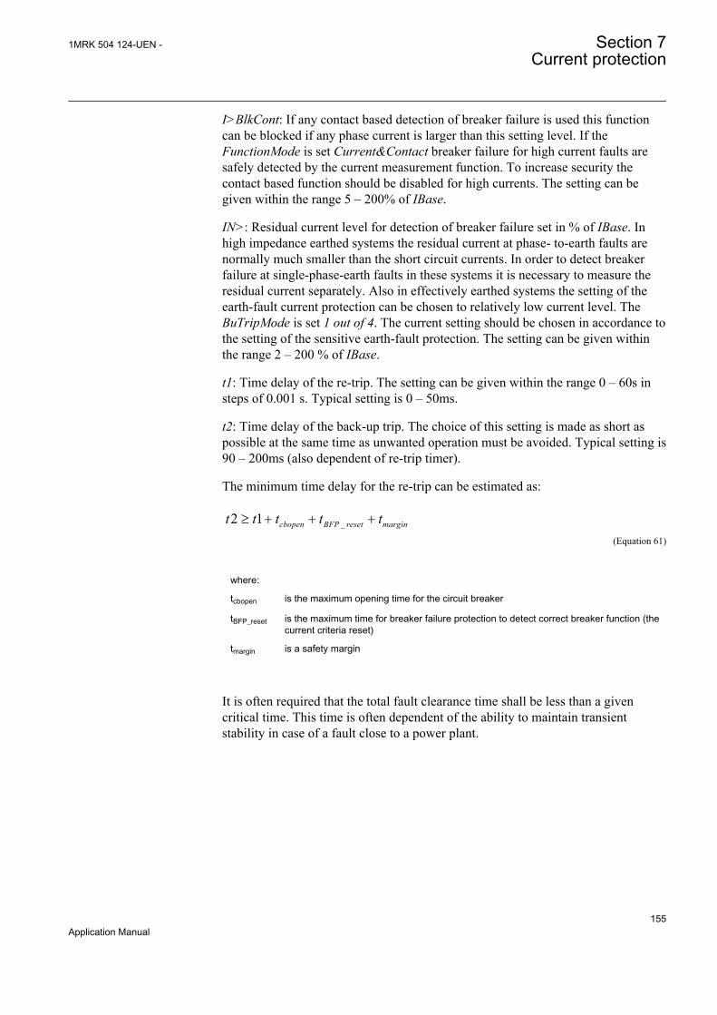
I>BlkCont: If any contact based detection of breaker failure is used this functioncan be blocked if any phase current is larger than this setting level. If theFunctionMode is set Current&Contact breaker failure for high current faults aresafely detected by the current measurement function. To increase security thecontact based function should be disabled for high currents. The setting can begiven within the range 5 – 200% of IBase.
IN>: Residual current level for detection of breaker failure set in % of IBase. Inhigh impedance earthed systems the residual current at phase- to-earth faults arenormally much smaller than the short circuit currents. In order to detect breakerfailure at single-phase-earth faults in these systems it is necessary to measure theresidual current separately. Also in effectively earthed systems the setting of theearth-fault current protection can be chosen to relatively low current level. TheBuTripMode is set 1 out of 4. The current setting should be chosen in accordance tothe setting of the sensitive earth-fault protection. The setting can be given withinthe range 2 – 200 % of IBase.
t1: Time delay of the re-trip. The setting can be given within the range 0 – 60s insteps of 0.001 s. Typical setting is 0 – 50ms.
t2: Time delay of the back-up trip. The choice of this setting is made as short aspossible at the same time as unwanted operation must be avoided. Typical setting is90 – 200ms (also dependent of re-trip timer).
The minimum time delay for the re-trip can be estimated as:
_2 1³ + + +cbopen BFP reset margint t t t tEQUATION1430 V1 EN (Equation 61)
where:
tcbopen is the maximum opening time for the circuit breaker
tBFP_reset is the maximum time for breaker failure protection to detect correct breaker function (thecurrent criteria reset)
tmargin is a safety margin
It is often required that the total fault clearance time shall be less than a givencritical time. This time is often dependent of the ability to maintain transientstability in case of a fault close to a power plant.
1MRK 504 124-UEN - Section 7Current protection
155Application Manual
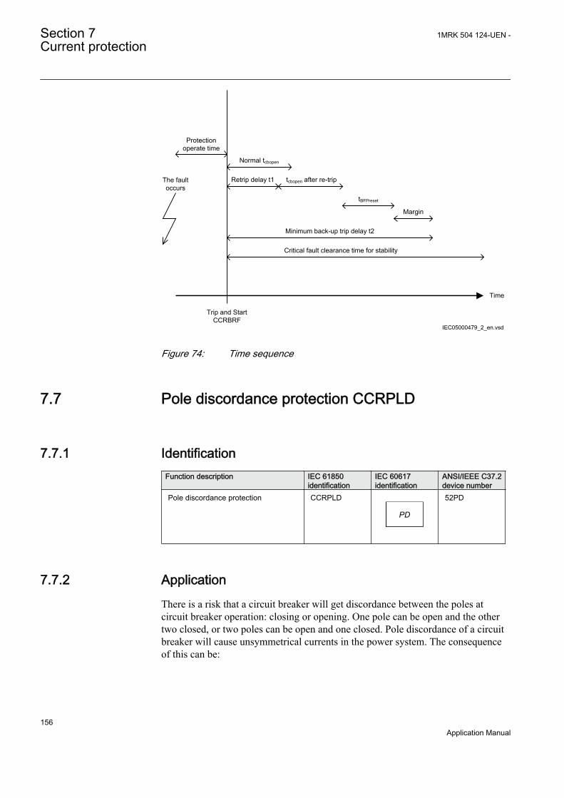
Time
The fault occurs
Protection operate time
Trip and Start CCRBRF
Normal tcbopen
Margin
Retrip delay t1 tcbopen after re-trip
tBFPreset
Minimum back-up trip delay t2
Critical fault clearance time for stability
IEC05000479_2_en.vsdIEC05000479 V2 EN
Figure 74: Time sequence
7.7 Pole discordance protection CCRPLD
7.7.1 IdentificationFunction description IEC 61850
identificationIEC 60617identification
ANSI/IEEE C37.2device number
Pole discordance protection CCRPLD
PD
SYMBOL-S V1 EN
52PD
7.7.2 ApplicationThere is a risk that a circuit breaker will get discordance between the poles atcircuit breaker operation: closing or opening. One pole can be open and the othertwo closed, or two poles can be open and one closed. Pole discordance of a circuitbreaker will cause unsymmetrical currents in the power system. The consequenceof this can be:
Section 7 1MRK 504 124-UEN -Current protection
156Application Manual
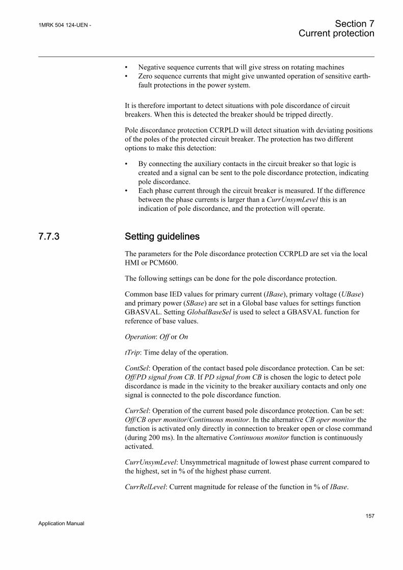
• Negative sequence currents that will give stress on rotating machines• Zero sequence currents that might give unwanted operation of sensitive earth-
fault protections in the power system.
It is therefore important to detect situations with pole discordance of circuitbreakers. When this is detected the breaker should be tripped directly.
Pole discordance protection CCRPLD will detect situation with deviating positionsof the poles of the protected circuit breaker. The protection has two differentoptions to make this detection:
• By connecting the auxiliary contacts in the circuit breaker so that logic iscreated and a signal can be sent to the pole discordance protection, indicatingpole discordance.
• Each phase current through the circuit breaker is measured. If the differencebetween the phase currents is larger than a CurrUnsymLevel this is anindication of pole discordance, and the protection will operate.
7.7.3 Setting guidelinesThe parameters for the Pole discordance protection CCRPLD are set via the localHMI or PCM600.
The following settings can be done for the pole discordance protection.
Common base IED values for primary current (IBase), primary voltage (UBase)and primary power (SBase) are set in a Global base values for settings functionGBASVAL. Setting GlobalBaseSel is used to select a GBASVAL function forreference of base values.
Operation: Off or On
tTrip: Time delay of the operation.
ContSel: Operation of the contact based pole discordance protection. Can be set:Off/PD signal from CB. If PD signal from CB is chosen the logic to detect polediscordance is made in the vicinity to the breaker auxiliary contacts and only onesignal is connected to the pole discordance function.
CurrSel: Operation of the current based pole discordance protection. Can be set:Off/CB oper monitor/Continuous monitor. In the alternative CB oper monitor thefunction is activated only directly in connection to breaker open or close command(during 200 ms). In the alternative Continuous monitor function is continuouslyactivated.
CurrUnsymLevel: Unsymmetrical magnitude of lowest phase current compared tothe highest, set in % of the highest phase current.
CurrRelLevel: Current magnitude for release of the function in % of IBase.
1MRK 504 124-UEN - Section 7Current protection
157Application Manual

7.8 Directional over-/under-power protectionGOPPDOP/GUPPDUP
7.8.1 ApplicationThe task of a generator in a power plant is to convert mechanical energy availableas a torque on a rotating shaft to electric energy.
Sometimes, the mechanical power from a prime mover may decrease so much thatit does not cover bearing losses and ventilation losses. Then, the synchronousgenerator becomes a synchronous motor and starts to take electric power from therest of the power system. This operating state, where individual synchronousmachines operate as motors, implies no risk for the machine itself. If the generatorunder consideration is very large and if it consumes lots of electric power, it maybe desirable to disconnect it to ease the task for the rest of the power system.
Often, the motoring condition may imply that the turbine is in a very dangerousstate. The task of the reverse power protection is to protect the turbine and not toprotect the generator itself.
Steam turbines easily become overheated if the steam flow becomes too low or ifthe steam ceases to flow through the turbine. Therefore, turbo-generators shouldhave reverse power protection. There are several contingencies that may causereverse power: break of a main steam pipe, damage to one or more blades in thesteam turbine or inadvertent closing of the main stop valves. In the last case, it ishighly desirable to have a reliable reverse power protection. It may prevent damageto an otherwise undamaged plant.
During the routine shutdown of many thermal power units, the reverse powerprotection gives the tripping impulse to the generator breaker (the unit breaker). Bydoing so, one prevents the disconnection of the unit before the mechanical powerhas become zero. Earlier disconnection would cause an acceleration of the turbinegenerator at all routine shutdowns. This should have caused overspeed and highcentrifugal stresses.
When the steam ceases to flow through a turbine, the cooling of the turbine bladeswill disappear. Now, it is not possible to remove all heat generated by the windagelosses. Instead, the heat will increase the temperature in the steam turbine andespecially of the blades. When a steam turbine rotates without steam supply, theelectric power consumption will be about 2% of rated power. Even if the turbinerotates in vacuum, it will soon become overheated and damaged. The turbineoverheats within minutes if the turbine loses the vacuum.
The critical time to overheating of a steam turbine varies from about 0.5 to 30minutes depending on the type of turbine. A high-pressure turbine with small andthin blades will become overheated more easily than a low-pressure turbine withlong and heavy blades. The conditions vary from turbine to turbine and it isnecessary to ask the turbine manufacturer in each case.
Section 7 1MRK 504 124-UEN -Current protection
158Application Manual

Power to the power plant auxiliaries may come from a station service transformerconnected to the primary side of the step-up transformer. Power may also comefrom a start-up service transformer connected to the external network. One has todesign the reverse power protection so that it can detect reverse power independentof the flow of power to the power plant auxiliaries.
Hydro turbines tolerate reverse power much better than steam turbines do. OnlyKaplan turbine and bulb turbines may suffer from reverse power. There is a riskthat the turbine runner moves axially and touches stationary parts. They are notalways strong enough to withstand the associated stresses.
Ice and snow may block the intake when the outdoor temperature falls far belowzero. Branches and leaves may also block the trash gates. A complete blockage ofthe intake may cause cavitations. The risk for damages to hydro turbines can justifyreverse power protection in unattended plants.
A hydro turbine that rotates in water with closed wicket gates will draw electricpower from the rest of the power system. This power will be about 10% of therated power. If there is only air in the hydro turbine, the power demand will fall toabout 3%.
Diesel engines should have reverse power protection. The generator will take about15% of its rated power or more from the system. A stiff engine may requireperhaps 25% of the rated power to motor it. An engine that is well run in mightneed no more than 5%. It is necessary to obtain information from the enginemanufacturer and to measure the reverse power during commissioning.
Gas turbines usually do not require reverse power protection.
Figure 75 illustrates the reverse power protection with underpower protection andwith overpower protection. The underpower protection gives a higher margin andshould provide better dependability. On the other hand, the risk for unwantedoperation immediately after synchronization may be higher. One should set theunderpower protection to trip if the active power from the generator is less thanabout 2%. One should set the overpower protection to trip if the power flow fromthe network to the generator is higher than 1%.
1MRK 504 124-UEN - Section 7Current protection
159Application Manual

Underpower protection Overpower protection
Q Q
P P
Operating point without turbine torque
Margin Margin
OperateLine
OperateLine
Operating point without turbine torque
IEC09000019-2-en.vsdIEC09000019 V2 EN
Figure 75: Reverse power protection with underpower or overpower protection
7.8.2 Directional over-power protection GOPPDOP
7.8.2.1 Identification
Function description IEC 61850identification
IEC 60617identification
ANSI/IEEE C37.2device number
Directional overpower protection GOPPDOPP >
DOCUMENT172362-IMG158942V1 EN
32
7.8.2.2 Setting guidelines
Common base IED values for primary current (IBase), primary voltage (UBase)and primary power (SBase) are set in a Global base values for settings functionGBASVAL. Setting GlobalBaseSel is used to select a GBASVAL function forreference of base values.
Operation: With the parameter Operation the function can be set On/Off.
Mode: The voltage and current used for the power measurement. The settingpossibilities are shown in table 20.
For reverse power applications PosSeq or Arone modes are strongly recommended.
Section 7 1MRK 504 124-UEN -Current protection
160Application Manual

Table 20: Complex power calculation
Set value Mode Formula used for complex power calculationL1, L2, L3 * * *
1 1 2 2 3 3L L L L L LS U I U I U I= × + × + ×
EQUATION1697 V1 EN (Equation 62)
Arone * *1 2 1 2 3 3L L L L L LS U I U I= × - ×
EQUATION1698 V1 EN (Equation 63)
PosSeq *3 PosSeq PosSeqS U I= × ×
EQUATION1699 V1 EN (Equation 64)
L1L2 * *1 2 1 2( )L L L LS U I I= × -
EQUATION1700 V1 EN (Equation 65)
L2L3 * *2 3 2 3( )L L L LS U I I= × -
EQUATION1701 V1 EN (Equation 66)
L3L1 * *3 1 3 1( )L L L LS U I I= × -
EQUATION1702 V1 EN (Equation 67)
L1 *1 13 L LS U I= × ×
EQUATION1703 V1 EN (Equation 68)
L2 *2 23 L LS U I= × ×
EQUATION1704 V1 EN (Equation 69)
L3 *3 33 L LS U I= × ×
EQUATION1705 V1 EN (Equation 70)
The function has two stages with the same setting parameters.
OpMode1(2) is set to define the function of the stage. Possible settings are:
On: the stage is activated Off: the stage is disabled
The function gives trip if the power component in the direction defined by thesetting Angle1(2) is larger than the set pick up power value Power1(2)
1MRK 504 124-UEN - Section 7Current protection
161Application Manual
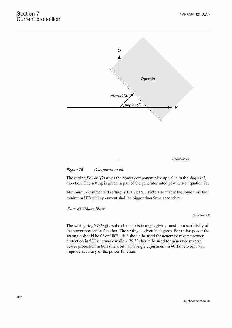
Operate
Angle1(2)
Power1(2)
P
Q
en06000440.vsdIEC06000440 V1 EN
Figure 76: Overpower mode
The setting Power1(2) gives the power component pick up value in the Angle1(2)direction. The setting is given in p.u. of the generator rated power, see equation 71.
Minimum recommended setting is 1.0% of SN. Note also that at the same time theminimum IED pickup current shall be bigger than 9mA secondary.
3NS UBase IBase= × ×
EQUATION1708 V1 EN (Equation 71)
The setting Angle1(2) gives the characteristic angle giving maximum sensitivity ofthe power protection function. The setting is given in degrees. For active power theset angle should be 0° or 180°. 180° should be used for generator reverse powerprotection in 50Hz network while -179.5° should be used for generator reversepower protection in 60Hz network. This angle adjustment in 60Hz networks willimprove accuracy of the power function.
Section 7 1MRK 504 124-UEN -Current protection
162Application Manual
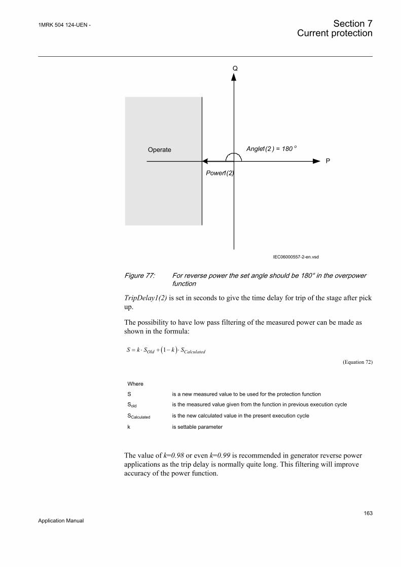
Operate Angle1(2 ) = 180 o
Power1(2)
P
Q
IEC06000557-2-en.vsdIEC06000557 V2 EN
Figure 77: For reverse power the set angle should be 180° in the overpowerfunction
TripDelay1(2) is set in seconds to give the time delay for trip of the stage after pickup.
The possibility to have low pass filtering of the measured power can be made asshown in the formula:
( )1Old CalculatedS k S k S= × + - ×
EQUATION1893 V1 EN (Equation 72)
Where
S is a new measured value to be used for the protection function
Sold is the measured value given from the function in previous execution cycle
SCalculated is the new calculated value in the present execution cycle
k is settable parameter
The value of k=0.98 or even k=0.99 is recommended in generator reverse powerapplications as the trip delay is normally quite long. This filtering will improveaccuracy of the power function.
1MRK 504 124-UEN - Section 7Current protection
163Application Manual
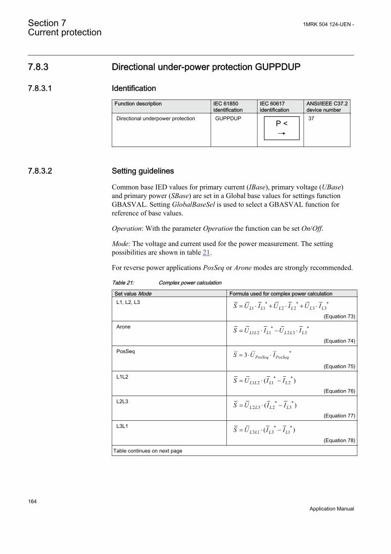
7.8.3 Directional under-power protection GUPPDUP
7.8.3.1 Identification
Function description IEC 61850identification
IEC 60617identification
ANSI/IEEE C37.2device number
Directional underpower protection GUPPDUPP <
SYMBOL-LL V1 EN
37
7.8.3.2 Setting guidelines
Common base IED values for primary current (IBase), primary voltage (UBase)and primary power (SBase) are set in a Global base values for settings functionGBASVAL. Setting GlobalBaseSel is used to select a GBASVAL function forreference of base values.
Operation: With the parameter Operation the function can be set On/Off.
Mode: The voltage and current used for the power measurement. The settingpossibilities are shown in table 21.
For reverse power applications PosSeq or Arone modes are strongly recommended.
Table 21: Complex power calculation
Set value Mode Formula used for complex power calculationL1, L2, L3 * * *
1 1 2 2 3 3L L L L L LS U I U I U I= × + × + ×
EQUATION1697 V1 EN (Equation 73)
Arone * *1 2 1 2 3 3L L L L L LS U I U I= × - ×
EQUATION1698 V1 EN (Equation 74)
PosSeq *3 PosSeq PosSeqS U I= × ×
EQUATION1699 V1 EN (Equation 75)
L1L2 * *1 2 1 2( )L L L LS U I I= × -
EQUATION1700 V1 EN (Equation 76)
L2L3 * *2 3 2 3( )L L L LS U I I= × -
EQUATION1701 V1 EN (Equation 77)
L3L1 * *3 1 3 1( )L L L LS U I I= × -
EQUATION1702 V1 EN (Equation 78)
Table continues on next page
Section 7 1MRK 504 124-UEN -Current protection
164Application Manual
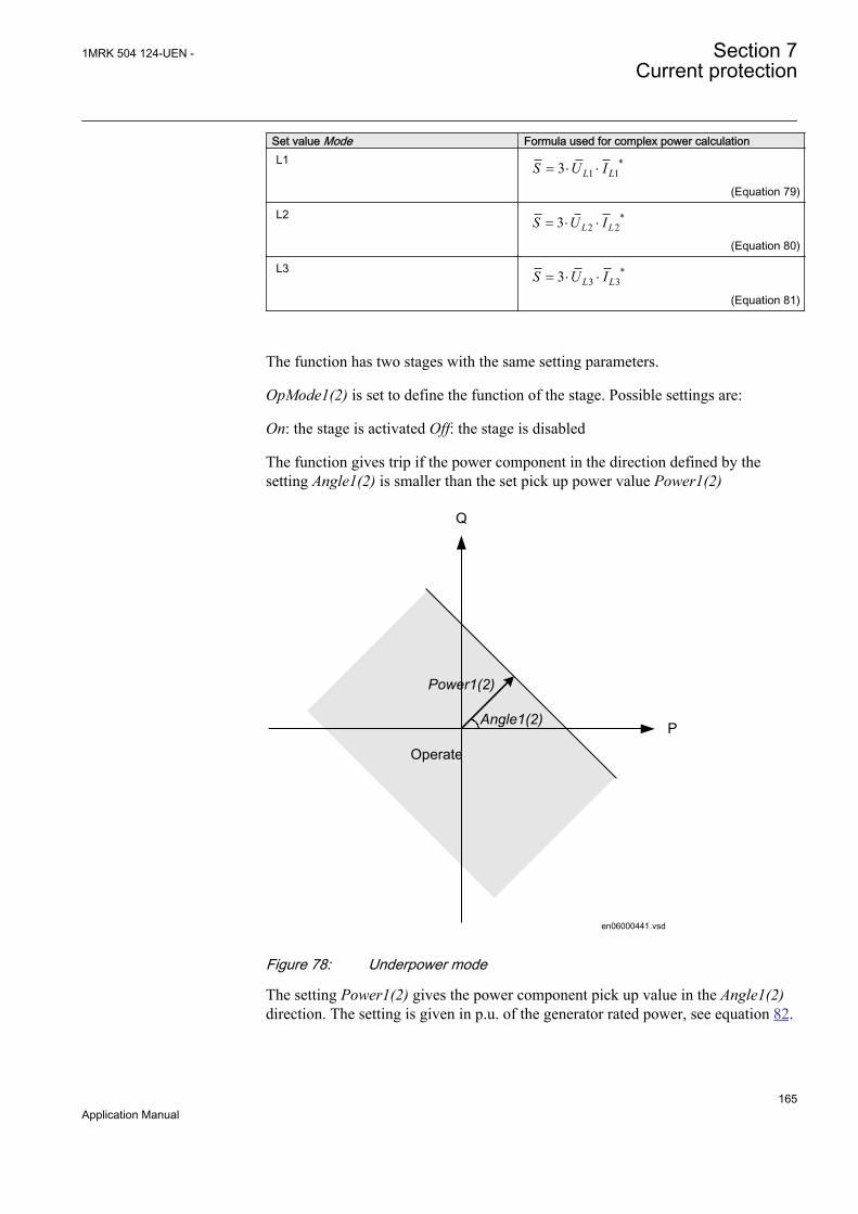
Set value Mode Formula used for complex power calculationL1 *
1 13 L LS U I= × ×
EQUATION1703 V1 EN (Equation 79)
L2 *2 23 L LS U I= × ×
EQUATION1704 V1 EN (Equation 80)
L3 *3 33 L LS U I= × ×
EQUATION1705 V1 EN (Equation 81)
The function has two stages with the same setting parameters.
OpMode1(2) is set to define the function of the stage. Possible settings are:
On: the stage is activated Off: the stage is disabled
The function gives trip if the power component in the direction defined by thesetting Angle1(2) is smaller than the set pick up power value Power1(2)
Operate
Angle1(2)
Power1(2)
P
Q
en06000441.vsdIEC06000441 V1 EN
Figure 78: Underpower mode
The setting Power1(2) gives the power component pick up value in the Angle1(2)direction. The setting is given in p.u. of the generator rated power, see equation 82.
1MRK 504 124-UEN - Section 7Current protection
165Application Manual

Minimum recommended setting is 1.0% of SN. Note also that at the same time theminimum IED pickup current shall be bigger than 9mA secondary.
3NS UBase IBase= × ×
EQUATION1708 V1 EN (Equation 82)
The setting Angle1(2) gives the characteristic angle giving maximum sensitivity ofthe power protection function. The setting is given in degrees. For active power theset angle should be 0° or 180°. 0° should be used for generator low forward activepower protection.
OperateAngle1(2) = 0°
Power1(2)
P
Q
en06000556.vsdIEC06000556 V1 EN
Figure 79: For low forward power the set angle should be 0° in theunderpower function
TripDelay1(2) is set in seconds to give the time delay for trip of the stage after pickup.
The possibility to have low pass filtering of the measured power can be made asshown in the formula:
Section 7 1MRK 504 124-UEN -Current protection
166Application Manual

( )1Old CalculatedS k S k S= × + - ×
EQUATION1893 V1 EN (Equation 83)
Where
S is a new measured value to be used for the protection function
Sold is the measured value given from the function in previous execution cycle
SCalculated is the new calculated value in the present execution cycle
k is settable parameter
The value of k=0.98 or even k=0.99 is recommended in generator low forwardpower applications as the trip delay is normally quite long. This filtering willimprove accuracy of the power function.
7.9 Negative sequence based overcurrent functionDNSPTOC
7.9.1 IdentificationFunction description IEC 61850
identificationIEC 60617identification
ANSI/IEEE C37.2device number
Negative sequence based overcurrentfunction
DNSPTOC
3I2>
IEC09000132 V2 EN
46
7.9.2 ApplicationNegative sequence based overcurrent function (DNSPTOC) is typically used assensitive earth-fault protection of power lines, where incorrect zero sequencepolarization may result from mutual induction between two or more parallel lines.
Additionally, it is applied in applications on underground cables, where zerosequence impedance depends on the fault current return paths, but the cablenegative sequence impedance is practically constant.
The directional function is current and voltage polarized. The function can be set toforward, reverse or non-directional independently for each step.
DNSPTOC protects against all unbalanced faults including phase-to-phase faults.The minimum start current of the function must be set to above the normal systemunbalance level in order to avoid unintentional functioning.
1MRK 504 124-UEN - Section 7Current protection
167Application Manual
7.9.3 Setting guidelinesBelow is an example of Negative sequence based overcurrent function(DNSPTOC) used as a sensitive earth-fault protection for power lines. Thefollowing settings must be done in order to ensure proper operation of the protection:
Common base IED values for primary current (IBase), primary voltage (UBase)and primary power (SBase) are set in a Global base values for settings functionGBASVAL. Setting GlobalBaseSel is used to select a GBASVAL function forreference of base values.
• setting RCA_DIR to value +65 degrees, that is, the negative sequence currenttypically lags the inverted negative sequence voltage for this angle during thefault
• setting ROA_DIR to value 90 degrees• setting LowVolt_VM to value 2%, that is, the negative sequence voltage level
above which the directional element will be enabled• setting Operation_OC1 to On• setting StartCurr_OC1 to value between 3-10%, (typical values)• setting tDef_OC1 to insure proper time coordination with other earth-fault
protections installed in the vicinity of this power line• setting DirMode_OC1 to Forward• setting DirPrinc_OC1 to IcosPhi&U• setting ActLowVolt1_VM to Block
DNSPTOC is used in directional comparison protection scheme for the power lineprotection, when communication channels to the remote end of this power line areavailable. In that case, two negative sequence overcurrent steps are required - onein forward and another in reverse direction. The OC1 stage is used to detect faultsin forward direction and the OC2 stage is used to detect faults in reverse direction.
However, the following must be noted for such application:
• setting RCA_Dir and ROA_Dir are applicable for both steps OC1 and OC2• setting DirMode_OC1 must be set to Forward• setting DirMode_OC2 must be set to Reverse• setting StartCurr_OC2 must be made more sensitive than pickup value of the
forward OC1 element, that is, typically 60% of StartCurr_OC1 set pickuplevel in order to insure proper operation of the directional comparison schemeduring current reversal situations
• the start signals STOC1 and STOC2 from OC1 and OC2 elements is used tosend forward and reverse signals to the remote end of the power line
• the available scheme communications function block within IED is usedbetween the protection function and the teleprotection communicationequipment, in order to insure proper conditioning of the above two start signals.
Section 7 1MRK 504 124-UEN -Current protection
168Application Manual

Section 8 Voltage protection
8.1 Two step undervoltage protection UV2PTUV
8.1.1 IdentificationFunction description IEC 61850
identificationIEC 60617identification
ANSI/IEEE C37.2device number
Two step undervoltage protection UV2PTUV
2U<
SYMBOL-R-2U-GREATER THANV1 EN
27
8.1.2 ApplicationTwo-step undervoltage protection function (UV2PTUV) is applicable in allsituations, where reliable detection of low phase voltages is necessary. It is usedalso as a supervision and fault detection function for other protection functions, toincrease the security of a complete protection system.
UV2PTUV is applied to power system elements, such as generators, transformers,motors and power lines in order to detect low voltage conditions. Low voltageconditions are caused by abnormal operation or fault in the power system.UV2PTUV is used in combination with overcurrent protections, either as restraintor in logic "and gates" of the trip signals issued by the two functions. Otherapplications are the detection of "no voltage" condition, for example, before theenergization of a HV line or for automatic breaker trip in case of a blackout.UV2PTUV is also used to initiate voltage correction measures, like insertion ofshunt capacitor banks to compensate for reactive load and thereby increasing thevoltage. The function has a high measuring accuracy to allow applications tocontrol reactive load.
UV2PTUV is used to disconnect from the network apparatuses, like electricmotors, which will be damaged when subject to service under low voltageconditions. UV2PTUV deals with low voltage conditions at power systemfrequency, which can be caused by the following reasons:
1. Malfunctioning of a voltage regulator or wrong settings under manual control(symmetrical voltage decrease).
2. Overload (symmetrical voltage decrease).3. Short circuits, often as phase-to-earth faults (unsymmetrical voltage decrease).
1MRK 504 124-UEN - Section 8Voltage protection
169Application Manual

UV2PTUV prevents sensitive equipment from running under conditions that couldcause their overheating and thus shorten their life time expectancy. In many cases,it is a useful function in circuits for local or remote automation processes in thepower system.
8.1.3 Setting guidelinesThe parameters for Two step undervoltage protection UV2PTUV are set via thelocal HMI or PCM600.
All the voltage conditions in the system where UV2PTUV performs its functionsshould be considered. The same also applies to the associated equipment, itsvoltage and time characteristic.
There is a very wide application area where general undervoltage functions areused. All voltage related settings are made as a percentage of the global settingsbase voltage UBase, which normally is set to the primary nominal voltage level(phase-to-phase) of the power system or the high voltage equipment underconsideration.
The setting for UV2PTUV is normally not critical, since there must be enough timeavailable for the main protection to clear short circuits and earth faults.
Some applications and related setting guidelines for the voltage level are describedin the following sections.
8.1.3.1 Equipment protection, such as for motors and generators
The setting must be below the lowest occurring "normal" voltage and above thelowest acceptable voltage for the equipment.
8.1.3.2 Disconnected equipment detection
The setting must be below the lowest occurring "normal" voltage and above thehighest occurring voltage, caused by inductive or capacitive coupling, when theequipment is disconnected.
8.1.3.3 Power supply quality
The setting must be below the lowest occurring "normal" voltage and above thelowest acceptable voltage, due to regulation, good practice or other agreements.
8.1.3.4 Voltage instability mitigation
This setting is very much dependent on the power system characteristics, andthorough studies have to be made to find the suitable levels.
Section 8 1MRK 504 124-UEN -Voltage protection
170Application Manual

8.1.3.5 Backup protection for power system faults
The setting must be below the lowest occurring "normal" voltage and above thehighest occurring voltage during the fault conditions under consideration.
8.1.3.6 Settings for Two step undervoltage protection
The following settings can be done for two step undervoltage protection (UV2PTUV).
Common base IED values for primary current (IBase), primary voltage (UBase)and primary power (SBase) are set in a Global base values for settings functionGBASVAL. Setting GlobalBaseSel is used to select a GBASVAL function forreference of base values.
ConnType: Sets whether the measurement shall be phase-to-earth fundamentalvalue, phase-to-phase fundamental value, phase-to-earth RMS value or phase-to-phase RMS value.
Operation: Off/On.
UV2PTUV measures selectively phase-to-earth voltages, or phase-to-phase voltagechosen by the setting ConnType.
This means operation for phase-to-earth voltage if:
(%) ( )3
U UBase kV< ×
EQUATION1447 V1 EN (Equation 84)
and operation for phase-to-phase voltage if:
U (%) UBase(kV)< ×EQUATION1990 V1 EN (Equation 85)
Characteristic1: This parameter gives the type of time delay to be used for step 1.The setting can be. Definite time/Inverse Curve A/Inverse Curve B. The choice ishighly dependent of the protection application.
OpModen: This parameter describes how many of the three measured voltages thatshould be below the set level to give operation for step n (n=step 1 and 2). Thesetting can be 1 out of 3, 2 out of 3 or 3 out of 3. In most applications it is sufficientthat one phase voltage is low to give operation. If the function shall be insensitivefor single phase-to-earth faults 2 out of 3 can be chosen.
Un<: Set operate undervoltage operation value for step n (n=step 1 and 2), given as% of the global parameter UBase. The setting is highly dependent of the protectionapplication. Here it is essential to consider the minimum voltage at non-faultedsituations. Normally this voltage is larger than 90% of nominal voltage.
1MRK 504 124-UEN - Section 8Voltage protection
171Application Manual
tn: time delay for step n (n=step 1 and 2), given in s. The setting is highlydependent of the protection application. In many applications the protectionfunction shall not directly trip in case of short circuits or earth faults in the system.The time delay must be coordinated to the short circuit protections.
t1Min: Minimum operation time for inverse time characteristic for step 1, given ins. For very low voltages the undervoltage function, using inverse timecharacteristic, can give very short operation time. This might lead to unselectivetrip. By setting t1Min longer than the operation time for other protections suchunselective tripping can be avoided.
k1: Time multiplier for inverse time characteristic. This parameter is used forcoordination between different inverse time delayed undervoltage protections.
The function must be externally blocked when the protected objectis disconnected.
8.2 Two step overvoltage protection OV2PTOV
8.2.1 IdentificationFunction description IEC 61850
identificationIEC 60617identification
ANSI/IEEE C37.2device number
Two step overvoltage protection OV2PTOV
2U>
SYMBOL-C-2U SMALLER THANV1 EN
59
8.2.2 ApplicationTwo step overvoltage protection OV2PTOV is applicable in all situations, wherereliable detection of high voltage is necessary. OV2PTOV is used for supervisionand detection of abnormal conditions, which, in combination with other protectionfunctions, increase the security of a complete protection system.
High voltage conditions are caused by abnormal situations in the power system.OV2PTOV is applied to power system elements, such as generators, transformers,motors and power lines in order to detect high voltage conditions. OV2PTOV isused in combination with low current signals, to identify a transmission line, openin the remote end. In addition to that, OV2PTOV is also used to initiate voltagecorrection measures, like insertion of shunt reactors, to compensate for low load,and thereby decreasing the voltage. The function has a high measuring accuracyand setting hysteresis to allow applications to control reactive load.
Section 8 1MRK 504 124-UEN -Voltage protection
172Application Manual
OV2PTOV is used to disconnect, from the network, apparatuses, like electricmotors, which will be damaged when subject to service under high voltageconditions. It deals with high voltage conditions at power system frequency, whichcan be caused by:
1. Different kinds of faults, where a too high voltage appears in a certain powersystem, like metallic connection to a higher voltage level (broken conductorfalling down to a crossing overhead line, transformer flash over fault from thehigh voltage winding to the low voltage winding and so on).
2. Malfunctioning of a voltage regulator or wrong settings under manual control(symmetrical voltage decrease).
3. Low load compared to the reactive power generation (symmetrical voltagedecrease).
4. Earth-faults in high impedance earthed systems causes, beside the high voltagein the neutral, high voltages in the two non-faulted phases, (unsymmetricalvoltage increase).
OV2PTOV prevents sensitive equipment from running under conditions that couldcause their overheating or stress of insulation material, and, thus, shorten their lifetime expectancy. In many cases, it is a useful function in circuits for local orremote automation processes in the power system.
8.2.3 Setting guidelinesThe parameters for Two step overvoltage protection (OV2PTOV) are set via thelocal HMI or PCM600.
All the voltage conditions in the system where OV2PTOV performs its functionsshould be considered. The same also applies to the associated equipment, itsvoltage and time characteristic.
There is a very wide application area where general overvoltage functions are used.All voltage related settings are made as a percentage of a settable base primaryvoltage, which normally is set to the nominal voltage level (phase-to-phase) of thepower system or the high voltage equipment under consideration.
The time delay for the OV2PTOV can sometimes be critical and related to the sizeof the overvoltage - a power system or a high voltage component can withstandsmaller overvoltages for some time, but in case of large overvoltages the relatedequipment should be disconnected more rapidly.
Some applications and related setting guidelines for the voltage level are given below:
Equipment protection, such as for motors, generators, reactors andtransformersHigh voltage can cause overexcitation of the core and deteriorate the windinginsulation. The setting must be above the highest occurring "normal" voltage andbelow the highest acceptable voltage for the equipment.
1MRK 504 124-UEN - Section 8Voltage protection
173Application Manual
Equipment protection, capacitorsHigh voltage can deteriorate the dielectricum and the insulation. The setting mustbe above the highest occurring "normal" voltage and below the highest acceptablevoltage for the capacitor.
High impedance earthed systemsIn high impedance earthed systems, earth-faults cause a voltage increase in the non-faulty phases. OV2PTOV can be used to detect such faults. The setting must beabove the highest occurring "normal" voltage and below the lowest occurringvoltage during faults. A metallic single-phase earth-fault causes the non-faultedphase voltages to increase a factor of √3.
The following settings can be done for Two step overvoltage protectionCommon base IED values for primary current (IBase), primary voltage (UBase)and primary power (SBase) are set in a Global base values for settings functionGBASVAL. Setting GlobalBaseSel is used to select a GBASVAL function forreference of base values.
ConnType: Sets whether the measurement shall be phase-to-earth fundamentalvalue, phase-to-phase fundamental value, phase-to-earth RMS value or phase-to-phase RMS value.
Operation: Off/On .
OV2PTOV measures the phase-to-earth voltages, or phase-to-phase voltages asselected. The function will operate if the voltage gets higher than the set percentageof the global set base voltage UBase. This means operation for phase-to-earthvoltage over:
( )(%)3
UBase kVU > ×
IEC09000054 V1 EN (Equation 86)
and operation for phase-to-phase voltage over:
U (%) UBase(kV)> ×EQUATION1993 V1 EN (Equation 87)
Characteristic1: This parameter gives the type of time delay to be used. The settingcan be. Definite time/Inverse Curve A/Inverse Curve B/Inverse Curve C. Thechoice is highly dependent of the protection application.
OpModen: This parameter describes how many of the three measured voltages thatshould be above the set level to give operation for step n (n=step 1 and 2). Thesetting can be 1 out of 3, 2 out of 3 or 3 out of 3. In most applications it is sufficientthat one phase voltage is high to give operation. If the function shall be insensitivefor single phase-to-earth faults 3 out of 3 can be chosen, because the voltage willnormally rise in the non-faulted phases at single phase-to-earth faults.
Section 8 1MRK 504 124-UEN -Voltage protection
174Application Manual

Un>: Set operate overvoltage operation value for step n (n=step 1 and 2), given as% of the global parameter UBase. The setting is highly dependent of the protectionapplication. Here it is essential to consider the Maximum voltage at non-faultedsituations. Normally this voltage is less than 110% of nominal voltage.
tn: time delay for step n (n=step 1 and 2), given in s. The setting is highlydependent of the protection application. In many applications the protectionfunction has the task to prevent damages to the protected object. The speed mightbe important for example in case of protection of transformer that might beoverexcited. The time delay must be co-ordinated with other automated actions inthe system.
t1Min: Minimum operation time for inverse time characteristic for step 1, given ins. For very high voltages the overvoltage function, using inverse timecharacteristic, can give very short operation time. This might lead to unselectivetrip. By setting t1Min longer than the operation time for other protections suchunselective tripping can be avoided.
k1: Time multiplier for inverse time characteristic. This parameter is used for co-ordination between different inverse time delayed undervoltage protections.
8.3 Two step residual overvoltage protectionROV2PTOV
8.3.1 IdentificationFunction description IEC 61850
identificationIEC 60617identification
ANSI/IEEE C37.2device number
Two step residual overvoltageprotection
ROV2PTOV
3U0>
IEC10000168 V1 EN
59N
8.3.2 ApplicationTwo step residual overvoltage protection ROV2PTOV is primarily used in highimpedance earthed distribution networks, mainly as a backup for the primary earth-fault protection of the feeders and the transformer. To increase the security fordifferent earth-fault related functions, the residual overvoltage signal can be usedas a release signal. The residual voltage can be measured either at the transformerneutral or from a voltage transformer open delta connection. The residual voltagecan also be calculated internally, based on measurement of the three-phase voltages.
In high impedance earthed systems the system neutral voltage, that is, the residualvoltage, will increase in case of any fault connected to earth. Depending on thetype of fault and fault resistance the residual voltage will reach different values.
1MRK 504 124-UEN - Section 8Voltage protection
175Application Manual

The highest residual voltage, equal to three times the phase-to-earth voltage, isachieved for a single phase-to-earth fault. The residual voltage increasesapproximately the same amount in the whole system and does not provide anyguidance in finding the faulted component. Therefore, ROV2PTOV is often usedas a backup protection or as a release signal for the feeder earth-fault protection.
8.3.3 Setting guidelinesThe parameters for Two step residual overvoltage protection ROV2PTOV are setvia the local HMI or PCM600.
All the voltage conditions in the system where ROV2PTOV performs its functionsshould be considered. The same also applies to the associated equipment, itsvoltage and time characteristic.
There is a very wide application area where general single input or residualovervoltage functions are used. All voltage related settings are made as apercentage of a settable base voltage, which can be set to the primary nominalvoltage (phase-phase) level of the power system or the high voltage equipmentunder consideration.
The time delay for ROV2PTOV are seldom critical, since residual voltage isrelated to earth-faults in a high impedance earthed system, and enough time mustnormally be given for the primary protection to clear the fault. In some morespecific situations, where the single overvoltage protection is used to protect somespecific equipment, the time delay is shorter.
Some applications and related setting guidelines for the residual voltage level aregiven below.
8.3.3.1 Equipment protection, such as for motors, generators, reactors andtransformers
High residual voltage indicates earth-fault in the system, perhaps in the componentto which Two step residual overvoltage protection (ROV2PTOV) is connected.After a period of time delay, to give the primary protection for the faulted device achance to trip, ROV2PTOV must trip the component. The setting must be abovethe highest occurring "normal" residual voltage and below the highest acceptableresidual voltage for the equipment
8.3.3.2 Power supply quality
The setting must be above the highest occurring "normal" residual voltage andbelow the highest acceptable residual voltage, due to regulation, good practice orother agreements.
Section 8 1MRK 504 124-UEN -Voltage protection
176Application Manual
8.3.3.3 High impedance earthed systems
In high impedance earthed systems, earth faults cause a neutral voltage in thefeeding transformer neutral. Two step residual overvoltage protection ROV2PTOVis used to trip the transformer, as a backup protection for the feeder earth-faultprotection, and as a backup for the transformer primary earth-fault protection. Thesetting must be above the highest occurring "normal" residual voltage, and belowthe lowest occurring residual voltage during the faults under consideration. Ametallic single-phase earth fault causes a transformer neutral to reach a voltageequal to the normal phase-to-earth voltage.
The voltage transformers measuring the phase-to-earth voltages measure zerovoltage in the faulty phase. The two healthy phases will measure full phase-to-phase voltage, as the earth is available on the faulty phase and the neutral has a fullphase-to-earth voltage. The residual overvoltage will be three times the phase-to-earth voltage. See Figure 80.
1MRK 504 124-UEN - Section 8Voltage protection
177Application Manual

IEC07000190 V1 EN
Figure 80: Non-effectivelyearthedsystems
8.3.3.4 Direct earthed system
In direct earthed systems, an earth-fault on one phase indicates a voltage collapsein that phase. The two healthy phases will have normal phase-to-earth voltages.The residual sum will have the same value as phase-to-earth voltage. See Figure 81.
Section 8 1MRK 504 124-UEN -Voltage protection
178Application Manual
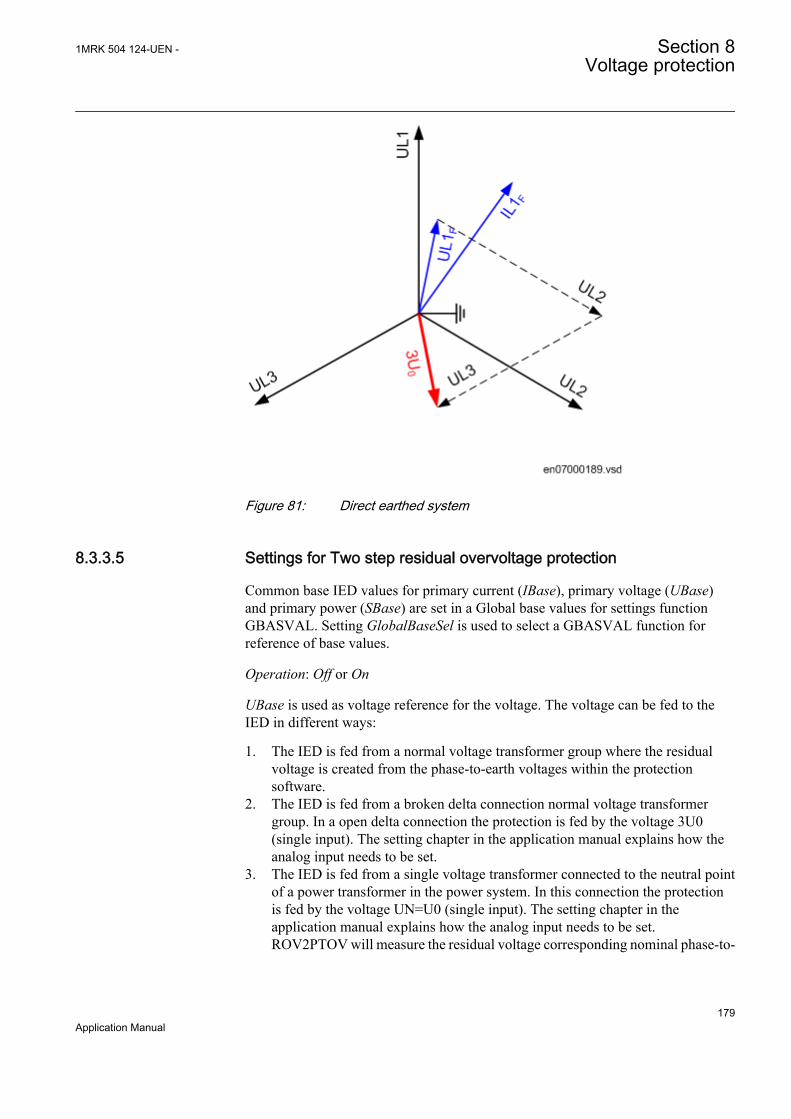
IEC07000189 V1 EN
Figure 81: Direct earthed system
8.3.3.5 Settings for Two step residual overvoltage protection
Common base IED values for primary current (IBase), primary voltage (UBase)and primary power (SBase) are set in a Global base values for settings functionGBASVAL. Setting GlobalBaseSel is used to select a GBASVAL function forreference of base values.
Operation: Off or On
UBase is used as voltage reference for the voltage. The voltage can be fed to theIED in different ways:
1. The IED is fed from a normal voltage transformer group where the residualvoltage is created from the phase-to-earth voltages within the protectionsoftware.
2. The IED is fed from a broken delta connection normal voltage transformergroup. In a open delta connection the protection is fed by the voltage 3U0(single input). The setting chapter in the application manual explains how theanalog input needs to be set.
3. The IED is fed from a single voltage transformer connected to the neutral pointof a power transformer in the power system. In this connection the protectionis fed by the voltage UN=U0 (single input). The setting chapter in theapplication manual explains how the analog input needs to be set.ROV2PTOV will measure the residual voltage corresponding nominal phase-to-
1MRK 504 124-UEN - Section 8Voltage protection
179Application Manual
earth voltage for high impedance earthed system. The measurement will bebased on the neutral voltage displacement .
Characteristic1: This parameter gives the type of time delay to be used. The settingcan be, Definite time or Inverse curve A or Inverse curve B or Inverse curve C. Thechoice is highly dependent of the protection application.
Un>: Set operate overvoltage operation value for step n (n=step 1 and 2), given as% of residual voltage corresponding to global set parameter UBase:
( ) ( )% 3U UBase kV> ×IECEQUATION2290 V1 EN
The setting is dependent of the required sensitivity of the protection and the systemearthing. In non-effectively earthed systems the residual voltage can be maximumthe rated phase-to-earth voltage, which should correspond to 100%.
In effectively earthed systems this value is dependent of the ratio Z0/Z1. Therequired setting to detect high resistive earth-faults must be based on networkcalculations.
tn: time delay of step n (n=step 1 and 2), given in s. The setting is highlydependent of the protection application. In many applications, the protectionfunction has the task to prevent damages to the protected object. The speed mightbe important for example in case of protection of transformer that might beoverexcited. The time delay must be co-ordinated with other automated actions inthe system.
t1Min: Minimum operation time for inverse time characteristic for step 1, given ins. For very high voltages the overvoltage function, using inverse timecharacteristic, can give very short operation time. This might lead to unselectivetrip. By setting t1Min longer than the operation time for other protections suchunselective tripping can be avoided.
k1: Time multiplier for inverse time characteristic. This parameter is used for co-ordination between different inverse time delayed undervoltage protections.
8.4 Overexcitation protection OEXPVPH
8.4.1 IdentificationFunction description IEC 61850
identificationIEC 60617identification
ANSI/IEEE C37.2device number
Overexcitation protection OEXPVPH
U/f >
SYMBOL-Q V1 EN
24
Section 8 1MRK 504 124-UEN -Voltage protection
180Application Manual
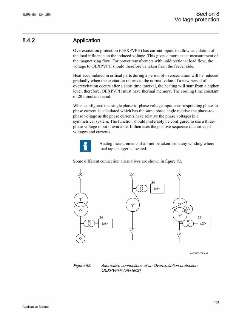
8.4.2 ApplicationOverexcitation protection (OEXPVPH) has current inputs to allow calculation ofthe load influence on the induced voltage. This gives a more exact measurement ofthe magnetizing flow. For power transformers with unidirectional load flow, thevoltage to OEXPVPH should therefore be taken from the feeder side.
Heat accumulated in critical parts during a period of overexcitation will be reducedgradually when the excitation returns to the normal value. If a new period ofoverexcitation occurs after a short time interval, the heating will start from a higherlevel, therefore, OEXPVPH must have thermal memory. The cooling time constantof 20 minutes is used.
When configured to a single phase-to-phase voltage input, a corresponding phase-to-phase current is calculated which has the same phase angle relative the phase-to-phase voltage as the phase currents have relative the phase voltages in asymmetrical system. The function should preferably be configured to use a three-phase voltage input if available. It then uses the positive sequence quantities ofvoltages and currents.
Analog measurements shall not be taken from any winding whereload tap changer is located.
Some different connection alternatives are shown in figure 82.
G
U/f>
24
U/f>
24
U/f>
24
en05000208.vsd
IEC05000208 V1 EN
Figure 82: Alternative connections of an Overexcitation protectionOEXPVPH(Volt/Hertz)
1MRK 504 124-UEN - Section 8Voltage protection
181Application Manual
8.4.3 Setting guidelines
8.4.3.1 Recommendations for input and output signals
Please refer to the Technical manual for a list of setting parameters.
Recommendations for Input signalsPlease see the default factory configuration.
BLOCK: The input will block the operation of the Overexcitation protectionOEXPVPH, for example, the block input can be used to block the operation for alimited time during special service conditions.
RESET: OEXPVPH has a thermal memory, which can take very long time toreset. Activation of the RESET input will reset the function.
Recommendations for Output signalsPlease see the default factory configuration for examples of configuration.
ERROR: The output indicates a measuring error. The reason, for example, can beconfiguration problems where analogue signals are missing.
START: The START output indicates that the level V/Hz>> has been reached. Itcan be used to initiate time measurement.
TRIP: The TRIP output is activated after the operate time for the U/f level hasexpired. TRIP signal is used to trip the circuit breaker(s).
ALARM: The output is activated when alarm level has been reached and the alarmtimer has elapsed. When the system voltage is high this output sends an alarm tothe operator.
8.4.3.2 Settings
The parameters for Overexcitation protection OEXPVPH are set via the local HMIor PCM600.
Common base IED values for primary current (IBase), primary voltage (UBase)and primary power (SBase) are set in a Global base values for settings functionGBASVAL. Setting GlobalBaseSel is used to select a GBASVAL function forreference of base values.
Operation: The operation of the Overexcitation protection OEXPVPH can be set toOn/Off.
V/Hz>: Operating level for the inverse characteristic. The operation is based on therelation between rated voltage and rated frequency and set as a percentage factor.Normal setting is around 108-110% depending of the capability curve for thetransformer/generator.
Section 8 1MRK 504 124-UEN -Voltage protection
182Application Manual
V/Hz>>: Operating level for the tMin definite time delay used at highovervoltages. The operation is based on the relation between rated voltage andrated frequency and set as a percentage factor. Normal setting is around 110-180%depending of the capability curve for the transformer/generator. Setting should beabove the knee-point when the characteristic starts to be straight on the high side.
kForIEEE: The time constant for the inverse characteristic. Select the one givingthe best match to the transformer capability.
tMin: The operating times at voltages higher than the set V/Hz>>. The setting shallmatch capabilities on these high voltages. Typical setting can be 1-10 second.
AlarmLevel: Setting of the alarm level in percentage of the set trip level. The alarmlevel is normally set at around 98% of the trip level.
tAlarm: Setting of the time to alarm is given from when the alarm level has beenreached. Typical setting is 5 seconds.
8.4.3.3 Service value report
A number of internal parameters are available as service values for use atcommissioning and during service. Remaining time to trip (in seconds)TMTOTRIP, flux density VPERHZ, internal thermal content in percentage of tripvalue THERMSTA. The values are available at local HMI, Substation SAsystemand PCM600.
1MRK 504 124-UEN - Section 8Voltage protection
183Application Manual

184
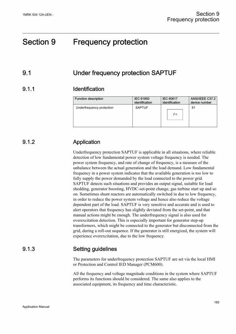
Section 9 Frequency protection
9.1 Under frequency protection SAPTUF
9.1.1 IdentificationFunction description IEC 61850
identificationIEC 60617identification
ANSI/IEEE C37.2device number
Underfrequency protection SAPTUF
f <
SYMBOL-P V1 EN
81
9.1.2 ApplicationUnderfrequency protection SAPTUF is applicable in all situations, where reliabledetection of low fundamental power system voltage frequency is needed. Thepower system frequency, and rate of change of frequency, is a measure of theunbalance between the actual generation and the load demand. Low fundamentalfrequency in a power system indicates that the available generation is too low tofully supply the power demanded by the load connected to the power grid.SAPTUF detects such situations and provides an output signal, suitable for loadshedding, generator boosting, HVDC-set-point change, gas turbine start up and soon. Sometimes shunt reactors are automatically switched in due to low frequency,in order to reduce the power system voltage and hence also reduce the voltagedependent part of the load. SAPTUF is very sensitive and accurate and is used toalert operators that frequency has slightly deviated from the set-point, and thatmanual actions might be enough. The underfrequency signal is also used foroverexcitation detection. This is especially important for generator step-uptransformers, which might be connected to the generator but disconnected from thegrid, during a roll-out sequence. If the generator is still energized, the system willexperience overexcitation, due to the low frequency.
9.1.3 Setting guidelinesThe parameters for underfrequency protection SAPTUF are set via the local HMIor Protection and Control IED Manager (PCM600).
All the frequency and voltage magnitude conditions in the system where SAPTUFperforms its functions should be considered. The same also applies to theassociated equipment, its frequency and time characteristic.
1MRK 504 124-UEN - Section 9Frequency protection
185Application Manual

There are especially two application areas for SAPTUF:
1. to protect equipment against damage due to low frequency, such as generators,transformers, and motors. Overexcitation is also related to low frequency
2. to protect a power system, or a part of a power system, against breakdown, byshedding load, in generation deficit situations.
The under frequency START value is set in Hz. All voltage magnitude relatedsettings are made as a percentage of a global base voltage parameter.
SAPTUF is not instantaneous, since the frequency is related to movements of thesystem inertia, but the time and frequency steps between different actions might becritical, and sometimes a rather short operation time is required, for example, downto 70 ms.
Some applications and related setting guidelines for the frequency level are givenbelow:
Equipment protection, such as for motors and generatorsThe setting has to be well below the lowest occurring "normal" frequency and wellabove the lowest acceptable frequency for the equipment.
Power system protection, by load sheddingThe setting has to be below the lowest occurring "normal" frequency and wellabove the lowest acceptable frequency for power stations, or sensitive loads. Thesetting level, the number of levels and the distance between two levels (in time and/or in frequency) depends very much on the characteristics of the power systemunder consideration. The size of the "largest loss of production" compared to "thesize of the power system" is a critical parameter. In large systems, the loadshedding can be set at a fairly high frequency level, and the time delay is normallynot critical. In smaller systems the frequency START level has to be set at a lowervalue, and the time delay must be rather short.
9.2 Over frequency protection SAPTOF
9.2.1 IdentificationFunction description IEC 61850
identificationIEC 60617identification
ANSI/IEEE C37.2device number
Overfrequency protection SAPTOF
f >
SYMBOL-O V1 EN
81
Section 9 1MRK 504 124-UEN -Frequency protection
186Application Manual
9.2.2 ApplicationOverfrequency protection function SAPTOF is applicable in all situations, wherereliable detection of high fundamental power system voltage frequency is needed.The power system frequency, and rate of change of frequency, is a measure of theunbalance between the actual generation and the load demand. High fundamentalfrequency in a power system indicates that the available generation is too largecompared to the power demanded by the load connected to the power grid.SAPTOF detects such situations and provides an output signal, suitable forgenerator shedding, HVDC-set-point change and so on. SAPTOF is very sensitiveand accurate and can also be used to alert operators that frequency has slightlydeviated from the set-point, and that manual actions might be enough.
9.2.3 Setting guidelinesThe parameters for Overfrequency protection (SAPTOF) are set via local HMI orPCM600.
All the frequency and voltage magnitude conditions in the system where SAPTOFperforms its functions must be considered. The same also applies to the associatedequipment, its frequency and time characteristic.
There are especially two application areas for SAPTOF:
1. to protect equipment against damage due to high frequency, such asgenerators, and motors
2. to protect a power system, or a part of a power system, against breakdown, byshedding generation, in generation surplus situations.
The overfrequency start value is set in Hz. All voltage magnitude related settingsare made as a percentage of a settable global base voltage parameter UBase.
SAPTOF is not instantaneous, since the frequency is related to movements of thesystem inertia, but the time and frequency steps between different actions might becritical, and sometimes a rather short operation time is required, for example, downto 70 ms.
Some applications and related setting guidelines for the frequency level are givenbelow:
Equipment protection, such as for motors and generatorsThe setting has to be well above the highest occurring "normal" frequency and wellbelow the highest acceptable frequency for the equipment.
Power system protection, by generator sheddingThe setting must be above the highest occurring "normal" frequency and below thehighest acceptable frequency for power stations, or sensitive loads. The settinglevel, the number of levels and the distance between two levels (in time and/or in
1MRK 504 124-UEN - Section 9Frequency protection
187Application Manual

frequency) depend very much on the characteristics of the power system underconsideration. The size of the "largest loss of load" compared to "the size of thepower system" is a critical parameter. In large systems, the generator shedding canbe set at a fairly low frequency level, and the time delay is normally not critical. Insmaller systems the frequency START level has to be set at a higher value, and thetime delay must be rather short.
9.3 Rate-of-change frequency protection SAPFRC
9.3.1 IdentificationFunction description IEC 61850
identificationIEC 60617identification
ANSI/IEEE C37.2device number
Rate-of-change frequency protection SAPFRC
df/dt ><
SYMBOL-N V1 EN
81
9.3.2 ApplicationRate-of-change frequency protection (SAPFRC), is applicable in all situations,where reliable detection of change of the fundamental power system voltagefrequency is needed. SAPFRC can be used both for increasing frequency and fordecreasing frequency. SAPFRC provides an output signal, suitable for loadshedding or generator shedding, generator boosting, HVDC-set-point change, gasturbine start up. Very often SAPFRC is used in combination with a low frequencysignal, especially in smaller power systems, where loss of a fairly large generatorwill require quick remedial actions to secure the power system integrity. In suchsituations load shedding actions are required at a rather high frequency level, but incombination with a large negative rate-of-change of frequency the underfrequencyprotection can be used at a rather high setting.
9.3.3 Setting guidelinesThe parameters for Rate-of-change frequency protection SAPFRC are set via thelocal HMI or PCM600.
All the frequency and voltage magnitude conditions in the system where SAPFRCperforms its functions should be considered. The same also applies to theassociated equipment, its frequency and time characteristic.
There are especially two application areas for SAPFRC:
Section 9 1MRK 504 124-UEN -Frequency protection
188Application Manual

1. to protect equipment against damage due to high or to low frequency, such asgenerators, transformers, and motors
2. to protect a power system, or a part of a power system, against breakdown, byshedding load or generation, in situations where load and generation are not inbalance.
SAPFRC is normally used together with an overfrequency or underfrequencyfunction, in small power systems, where a single event can cause a large imbalancebetween load and generation. In such situations load or generation shedding has totake place very quickly, and there might not be enough time to wait until thefrequency signal has reached an abnormal value. Actions are therefore taken at afrequency level closer to the primary nominal level, if the rate-of-change frequencyis large (with respect to sign).
SAPFRCSTART value is set in Hz/s. All voltage magnitude related settings aremade as a percentage of a settable base voltage, which normally is set to theprimary nominal voltage level (phase-phase) of the power system or the highvoltage equipment under consideration.
SAPFRC is not instantaneous, since the function needs some time to supply astable value. It is recommended to have a time delay long enough to take care ofsignal noise. However, the time, rate-of-change frequency and frequency stepsbetween different actions might be critical, and sometimes a rather short operationtime is required, for example, down to 70 ms.
Smaller industrial systems might experience rate-of-change frequency as large as 5Hz/s, due to a single event. Even large power systems may form small islands witha large imbalance between load and generation, when severe faults (orcombinations of faults) are cleared - up to 3 Hz/s has been experienced when asmall island was isolated from a large system. For more "normal" severedisturbances in large power systems, rate-of-change of frequency is much less,most often just a fraction of 1.0 Hz/s.
1MRK 504 124-UEN - Section 9Frequency protection
189Application Manual

190

Section 10 Secondary system supervision
10.1 Breaker close/trip circuit monitoring TCSSCBR
10.1.1 Identification
Function description IEC 61850identification
IEC 60617identification
ANSI/IEEE C37.2device number
Breaker close/trip circuit monitoring TCSSCBR - -
10.1.2 ApplicationTCSSCBR detects faults in the electrical control circuit of the circuit breaker. Thefunction can supervise both open and closed coil circuits. This kind of supervisionis necessary to find out the vitality of the control circuits continuously.
Trip circuit supervision generates a current of approximately 1.0mA through the supervised circuit. It must be ensured that thiscurrent will not cause a latch up of the controlled object.
To protect the trip circuit supervision circuits in the IED, the outputcontacts are provided with parallel transient voltage suppressors.The breakdown voltage of these suppressors is 400 +/– 20 V DC.
1MRK 504 124-UEN - Section 10Secondary system supervision
191Application Manual

GUID-B056E9DB-E3E5-4300-9150-45916F485CA7 V1 EN
Figure 83: Operating principle of the trip-circuit supervision with an externalresistor. The TCSSCBR blocking switch is not required since theexternal resistor is used.
If TCS is required only in a closed position, the external shunt resistance can beomitted. When the circuit breaker is in the open position, TCS sees the situation asa faulty circuit. One way to avoid TCS operation in this situation would be to blockthe supervision function whenever the circuit breaker is open.
Section 10 1MRK 504 124-UEN -Secondary system supervision
192Application Manual
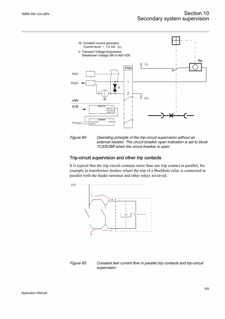
1
PSM
2
Rs
(+)
(-)
HW
SW PCM_TCSTCSOUT1TCSOUT2TCSOUT3
PO1
TCS1
IS
V
IS: Constant current generator. Current level ~ 1,0 mA (Ic)V: Transient Voltage Suppressor Breakdown Voltage 380 to 400 VDC
Ic
CBPOS_open
TCSSCBRTCS_STATEBLOCK
ALARM
GUID-6B09F9C7-86D0-4A7A-8E08-8E37CAE53249 V2 EN
Figure 84: Operating principle of the trip-circuit supervision without anexternal resistor. The circuit breaker open indication is set to blockTCSSCBR when the circuit breaker is open.
Trip-circuit supervision and other trip contactsIt is typical that the trip circuit contains more than one trip contact in parallel, forexample in transformer feeders where the trip of a Buchholz relay is connected inparallel with the feeder terminal and other relays involved.
GUID-7264738C-F9D7-48F0-B6FC-F85FD10D5B84 V1 EN
Figure 85: Constant test current flow in parallel trip contacts and trip-circuitsupervision
1MRK 504 124-UEN - Section 10Secondary system supervision
193Application Manual

Several trip-circuit supervision functions parallel in circuitNot only the trip circuit often have parallel trip contacts, it is also possible that thecircuit has multiple TCS circuits in parallel. Each TCS circuit causes its ownsupervising current to flow through the monitored coil and the actual coil current isa sum of all TCS currents. This must be taken into consideration when determiningthe resistance of Rext.
Trip-circuit supervision with auxiliary relaysMany retrofit projects are carried out partially, that is, the old electromechanicalrelays are replaced with new ones but the circuit breaker is not replaced. Thiscreates a problem that the coil current of an old type circuit breaker can be too highfor the protection IED trip contact to break.
The circuit breaker coil current is normally cut by an internal contact of the circuitbreaker. In case of a circuit breaker failure, there is a risk that the protection IEDtrip contact is destroyed since the contact is obliged to disconnect high level ofelectromagnetic energy accumulated in the trip coil.
An auxiliary relay can be used between the protection IED trip contact and thecircuit breaker coil. This way the breaking capacity question is solved, but the TCScircuit in the protection IED monitors the healthy auxiliary relay coil, not thecircuit breaker coil. The separate trip circuit supervision relay is applicable for thisto supervise the trip coil of the circuit breaker.
Dimensioning of the external resistorMathematically, the operation condition can be expressed as:
If the external shunt resistance is used, it has to be calculated not to interfere withthe functionality of the supervision or the trip coil. Too high a resistance causes toohigh a voltage drop, jeopardizing the requirement of at least 20 V over the internalcircuit, while a resistance too low can enable false operations of the trip coil.
At lower (<48V DC) auxiliary circuit operating voltages, it is recommended to usethe circuit breaker position to block unintentional operation of TCS. The use of theposition indication is described earlier in this chapter.
Section 10 1MRK 504 124-UEN -Secondary system supervision
194Application Manual

Section 11 Control
11.1 Apparatus control
11.1.1 IdentificationFunction description IEC 61850
identificationIEC 60617identification
ANSI/IEEE C37.2device number
Bay control QCBAY - -
Local remote LOCREM - -
Local remote control LOCREMCTRL - -
11.1.2 ApplicationThe apparatus control is a function for control and supervising of circuit breakers,disconnectors, and earthing switches within a bay. Permission to operate is givenafter evaluation of conditions from other functions such as interlocking,synchrocheck, operator place selection and external or internal blockings.
The complete apparatus control function is not included in thisproduct, and the information below is included for understanding ofthe principle for the use of QCBAY, LOCREM, andLOCREMCTRL for the selection of the operator place.
Figure 86 gives an overview from what places the apparatus control functionreceive commands. Commands to an apparatus can be initiated from the ControlCentre (CC), the station HMI or the local HMI on the IED front.
1MRK 504 124-UEN - Section 11Control
195Application Manual
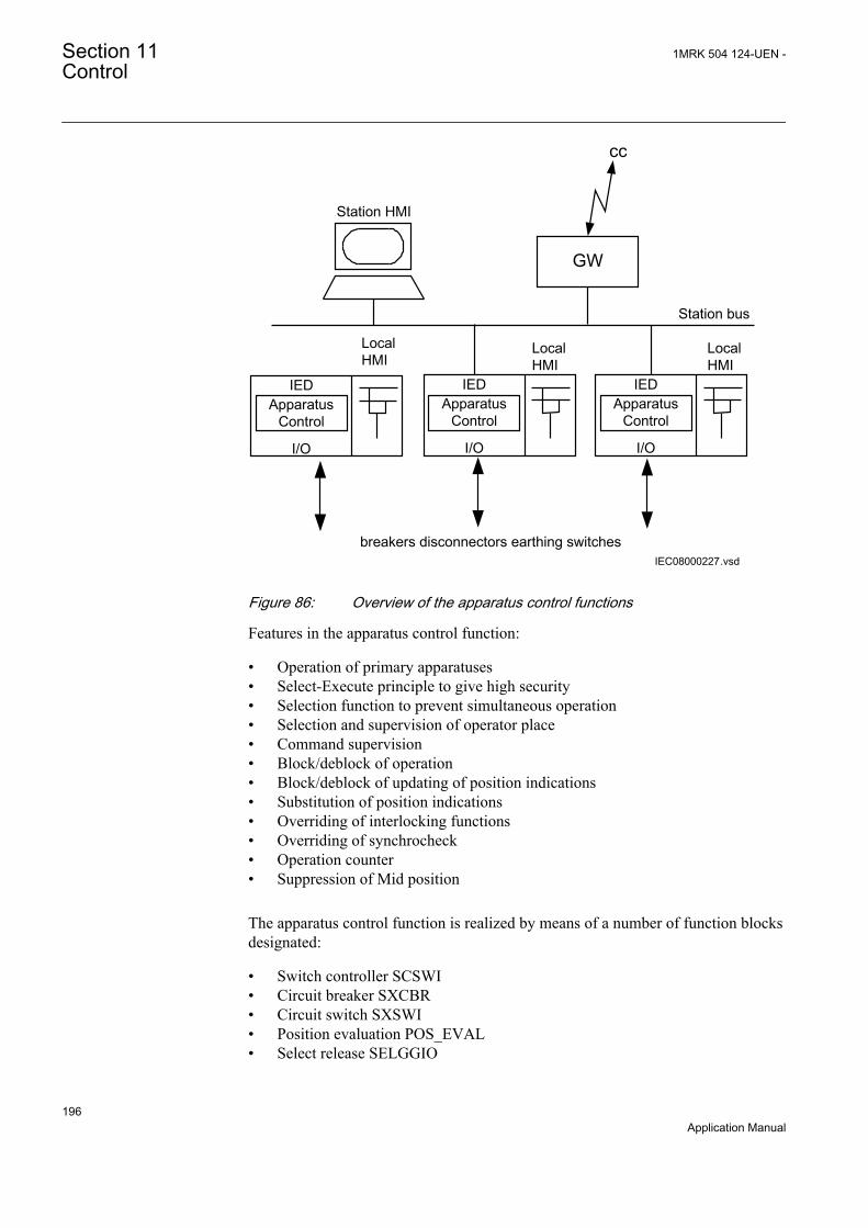
Station HMI
GW
cc
Station bus
breakers disconnectors earthing switchesIEC08000227.vsd
ApparatusControl
IED
I/O
Local HMI
ApparatusControl
IED
I/O
ApparatusControl
IED
I/O
Local HMI
Local HMI
IEC08000227 V1 EN
Figure 86: Overview of the apparatus control functions
Features in the apparatus control function:
• Operation of primary apparatuses• Select-Execute principle to give high security• Selection function to prevent simultaneous operation• Selection and supervision of operator place• Command supervision• Block/deblock of operation• Block/deblock of updating of position indications• Substitution of position indications• Overriding of interlocking functions• Overriding of synchrocheck• Operation counter• Suppression of Mid position
The apparatus control function is realized by means of a number of function blocksdesignated:
• Switch controller SCSWI• Circuit breaker SXCBR• Circuit switch SXSWI• Position evaluation POS_EVAL• Select release SELGGIO
Section 11 1MRK 504 124-UEN -Control
196Application Manual

• Bay control QCBAY• Local remote LOCREM• Local remote control LOCREMCTRL
SCSWI, SXCBR, QCBAY, SXSWI and SELGGIO are logical nodes according toIEC 61850. The signal flow between these function blocks appears in figure 87.The function Logical node Interlocking (SCILO) in the figure 87 is the logicalnode for interlocking.
Control operation can be performed from the local HMI. If the administrator hasdefined users with the UM tool, then the local/remote switch is under authoritycontrol. If not, the default (factory) user is the SuperUser that can perform controloperations from the local HMI without LogOn. The default position of the local/remote switch is on remote.
IEC09000338-1-en.vsd
SXCBRSCSWI
SCILO
SCSWI
SCILO
SXSWI
-QA1
-QB1
-QB9
IEC 61850
QCBAY
IEC09000338 V1 EN
Figure 87: Signal flow between apparatus control function blocks
Bay control (QCBAY)The Bay control (QCBAY) is used to handle the selection of the operator place forthe bay. The function gives permission to operate from two types of locationseither from Remote (for example, control centre or station HMI) or from Local
1MRK 504 124-UEN - Section 11Control
197Application Manual

(local HMI on the IED) or from all (Local and Remote). The Local/Remote switchposition can also be set to Off, which means no operator place selected that is,operation is not possible neither from local nor from remote.
QCBAY also provides blocking functions that can be distributed to differentapparatuses within the bay. There are two different blocking alternatives:
• Blocking of update of positions• Blocking of commands
The function does not have a corresponding functionality defined in the IEC 61850standard, which means that this function is included as a vendor specific logical node.
11.1.3 Interaction between modulesA typical bay with apparatus control function consists of a combination of logicalnodes or functions that are described here:
• The Switch controller (SCSWI) initializes all operations for one apparatus andperforms the actual switching and is more or less the interface to the drive ofone apparatus. It includes the position handling as well as the control of theposition.
• The Circuit breaker (SXCBR) is the process interface to the circuit breaker forthe apparatus control function.
• The Circuit switch (SXSWI) is the process interface to the disconnector or theearthing switch for the apparatus control function.
• The Bay control (QCBAY) fulfils the bay-level functions for the apparatuses,such as operator place selection and blockings for the complete bay.
• The function (SELGGIO), deals with reservation of the bay.• The Four step overcurrent protection (OC4PTOC) trips the breaker.• The Protection trip logic (SMPPTRC) connects the "trip" outputs of one or
more protection functions to a common "trip" to be transmitted to SXCBR.• The Autorecloser (SMBRREC) consists of the facilities to automatically close
a tripped breaker with respect to a number of configurable conditions.• The logical node Interlocking (SCILO) provides the information to SCSWI
whether it is permitted to operate due to the switchyard topology. Theinterlocking conditions are evaluated with separate logic and connected toSCILO.
• The Synchrocheck, energizing check, and synchronizing (SESRSYN)calculates and compares the voltage phasor difference from both sides of anopen breaker with predefined switching conditions (synchrocheck). Also thecase that one side is dead (energizing-check) is included.
• The logical node Generic Automatic Process Control, GAPC, is an automaticfunction that reduces the interaction between the operator and the system.With one command, the operator can start a sequence that will end with aconnection of a process object (for example a line) to one of the possible busbars.
The overview of the interaction between these functions is shown in figure 88 below.
Section 11 1MRK 504 124-UEN -Control
198Application Manual
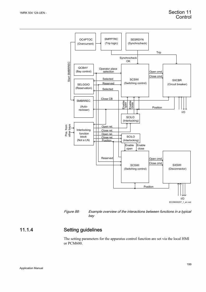
IEC09000207_1_en.vsd
OC4PTOC (Overcurrent)
SXCBR(Circuit breaker)
Interlockingfunctionblock
(Not a LN)
SCSWI(Switching control)
QCBAY(Bay control)
SMBRREC
(Auto-recloser)
I/O
Trip
Close rel.
Selected
Star
t SM
BRR
EC
Close CB
Position
Reserved
Operator placeselection
SCSWI(Switching control)
SXSWI(Disconnector)
Open cmd
Close cmd
Position
SESRSYN(Synchrocheck)
SCILO
SCILO
Synchrocheck OK
SELGGIO(Reservation) Selected
Reserved
Enable close
Enable open
Open rel.
Close rel.Open rel.
SMPPTRC(Trip logic)
Position
Enab
leop
en
Enab
lecl
ose
Pos.
from
ot
her b
ays
I/O
Open cmdClose cmd
(Interlocking)
(Interlocking)
IEC09000207 V1 EN
Figure 88: Example overview of the interactions between functions in a typicalbay
11.1.4 Setting guidelinesThe setting parameters for the apparatus control function are set via the local HMIor PCM600.
1MRK 504 124-UEN - Section 11Control
199Application Manual

11.1.4.1 Bay control (QCBAY)
If the parameter AllPSTOValid is set to No priority, all originators from local andremote are accepted without any priority.
11.2 Voltage control
11.2.1 IdentificationFunction description IEC 61850
identificationIEC 60617identification
ANSI/IEEE C37.2device number
Automatic voltage control for tapchanger
TR8ATCC
U
IEC10000166 V1 EN
90
Tap changer control and supervision, 6binary inputs
TCMYLTC
IEC10000167 V1 EN
84
11.2.2 ApplicationWhen the load in a power network is increased the voltage will decrease and viceversa. To maintain the network voltage at a constant level, power transformers areusually equipped with an load tap changer. This alters the power transformer ratioin a number of predefined steps and in that way changes the voltage. Each stepusually represents a change in voltage of approximately 0.5-1.7%.
The voltage control function is intended for control of power transformers with amotor driven load tap changer. The function is designed to regulate the voltage atthe secondary side of the power transformer. The control method is based on a step-by-step principle which means that a control pulse, one at a time, will be issued tothe tap changer mechanism to move it one position up or down. The length of thecontrol pulse can be set within a wide range to accommodate different types of tapchanger mechanisms. The pulse is generated whenever the measured voltage, for agiven time, deviates from the set reference value by more than the preset deadband(degree of insensitivity).
The voltage can be controlled at the point of voltage measurement, as well as aload point located out in the network. In the latter case, the load point voltage iscalculated based on the measured load current and the known impedance from thevoltage measuring point to the load point.
The automatic voltage control can be either for a single transformer, or for paralleltransformers. Parallel control of power transformers with an IED can be made inthree alternative ways:
Section 11 1MRK 504 124-UEN -Control
200Application Manual

• With the master-follower method• With the reverse reactance method• With the circulating current method
Of these alternatives, the first and the last require communication between thefunction control blocks of the different transformers, whereas the middlealternative does not require any communication.
The voltage control includes many extra features such as possibility to avoidsimultaneous tapping of parallel transformers, extensive tap changer monitoringincluding contact wear and hunting detection, monitoring of the power flow in thetransformer so that for example, the voltage control can be blocked if the powerreverses and so on.
The voltage control function is built up by two function blocks which both arelogical nodes in IEC 61850-8-1:
• Automatic voltage control for tap changer, TR8ATCC for parallel control.• Tap changer control and supervision, 6 binary inputs, TCMYLTC
Automatic voltage control for tap changer, TR8ATCC is a function designed toautomatically maintain the voltage at the LV-side side of a power transformerwithin given limits around a set target voltage. A raise or lower command isgenerated whenever the measured voltage, for a given period of time, deviates fromthe set target value by more than the preset deadband value (degree ofinsensitivity). A time delay (inverse or definite time) is set to avoid unnecessaryoperation during shorter voltage deviations from the target value, and in order tocoordinate with other automatic voltage controllers in the system.
TCMYLTCis an interface between the Automatic voltage control for tap changer,TR8ATCC and the transformer load tap changer itself. More specifically thismeans that it gives command-pulses to a power transformer motor driven load tapchanger and that it receives information from the load tap changer regarding tapposition, progress of given commands, and so on.
TCMYLTC also serves the purpose of giving information about tap position to thetransformer differential protection.
Control location local/remoteThe tap changer can be operated from the front of the IED or from a remote placealternatively. On the IED front there is a local remote switch that can be used toselect the operator place. For this functionality the Apparatus control functionblocks Bay control (QCBAY), Local remote (LOCREM) and Local remote control(LOCREMCTRL) are used.
Information about the control location is given to TR8ATCC function throughconnection of the Permitted Source to Operate (PSTO) output of the QCBAYfunction block to the input PSTO of the TR8ATCC function block.
1MRK 504 124-UEN - Section 11Control
201Application Manual
Control ModeThe control mode of the automatic voltage control for tap changer function,TR8ATCC for parallel control can be:
• Manual• Automatic
The control mode can be changed from the local location via the command menuon the local HMI under Main menu/ Control/Commands/TR8ATCC (90)/1:TR8ATCC, or changed from a remote location via binary signals connected tothe MANCTRL, AUTOCTRL inputs on TR8ATCC function block.
Measured QuantitiesIn normal applications, the LV side of the transformer is used as the voltagemeasuring point. If necessary, the LV side current is used as load current tocalculate the line-voltage drop to the regulation point.
Automatic voltage control for tap changer, TR8ATCC function block has threeinputs I3P1, I3P2 and U3P2 corresponding to HV-current, LV-current and LV-voltage respectively. These analog quantities are fed to the IED via the transformerinput module, the Analog to Digital Converter and thereafter a Pre-ProcessingBlock. In the Pre-Processing Block, a great number of quantities for example, phase-to-phase analog values, sequence values, max value in a three phase group etc., arederived. The different function blocks in the IED are then “subscribing” onselected quantities from the pre-processing blocks. In case of TR8ATCC, there arethe following possibilities:
• I3P1 represents a three-phase group of phase current with the highest currentin any of the three phases considered. As only the highest of the phase currentis considered, it is also possible to use one single-phase current as well as two-phase currents. In these cases, the currents that are not used will be zero.
• For I3P2 and U3P2 the setting alternatives are: any individual phase current/voltage, as well as any combination of phase-phase current/voltage or thepositive sequence current/voltage. Thus, single-phase as well as, phase-phaseor three-phase feeding on the LV-side is possible but it is commonly selectedfor current and voltage.
Section 11 1MRK 504 124-UEN -Control
202Application Manual

OLT
C
raise,lowersignals/alarms
positionBIO
AIM
IED
IL1,IL2,IL3
TRMIL1,IL2,IL3 or ILi,ILj or ILi
UL1,UL2,UL3 or ULi,ULj or ULi
High Voltage Side
(Load Current) IL
Low Voltage Side
Line Impedance R+jX
UB (Busbar Voltage)
Load Center UL (Load Point Voltage)
IEC11000064-1-en.vsdIEC11000064 V1 EN
Figure 89: Signal flow for a single transformer with voltage control
On the HV side, the three-phase current is normally required in order to feed the three-phase over current protection that blocks the load tap changer in case of over-current above harmful levels.
The voltage measurement on the LV-side can be made single phase-earth.However, it shall be remembered that this can only be used in solidly earthedsystems, as the measured phase-earth voltage can increase with as much as a factor√3 in case of earth faults in a non-solidly earthed system.
The analog input signals are normally common with other functions in the IED forexample, protection functions.
The LV-busbar voltage is designated UB, the load current IL andload point voltage UL.
Automatic voltage control for a single transformerAutomatic voltage control for tap changer, parallel control TR8ATCC measuresthe magnitude of the busbar voltage UB. If no other additional features are enabled(line voltage drop compensation), this voltage is further used for voltage regulation.
1MRK 504 124-UEN - Section 11Control
203Application Manual
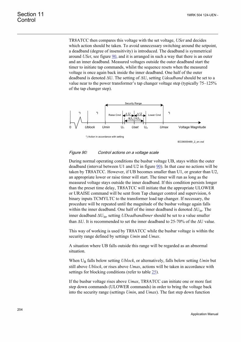
TR8ATCC then compares this voltage with the set voltage, USet and decideswhich action should be taken. To avoid unnecessary switching around the setpoint,a deadband (degree of insensitivity) is introduced. The deadband is symmetricalaround USet, see figure 90, and it is arranged in such a way that there is an outerand an inner deadband. Measured voltages outside the outer deadband start thetimer to initiate tap commands, whilst the sequence resets when the measuredvoltage is once again back inside the inner deadband. One half of the outerdeadband is denoted ΔU. The setting of ΔU, setting Udeadband should be set to avalue near to the power transformer’s tap changer voltage step (typically 75–125%of the tap changer step).
Voltage MagnitudeUmaxU2UsetU1UminUblock0
Raise Cmd
*) Action in accordance with setting
Security Range
Lower Cmd
IEC06000489_2_en.vsd
DD U UDUin DUin
*) *) *)
IEC06000489 V2 EN
Figure 90: Control actions on a voltage scale
During normal operating conditions the busbar voltage UB, stays within the outerdeadband (interval between U1 and U2 in figure 90). In that case no actions will betaken by TR8ATCC. However, if UB becomes smaller than U1, or greater than U2,an appropriate lower or raise timer will start. The timer will run as long as themeasured voltage stays outside the inner deadband. If this condition persists longerthan the preset time delay, TR8ATCC will initiate that the appropriate ULOWERor URAISE command will be sent from Tap changer control and supervision, 6binary inputs TCMYLTC to the transformer load tap changer. If necessary, theprocedure will be repeated until the magnitude of the busbar voltage again fallswithin the inner deadband. One half of the inner deadband is denoted ΔUin. Theinner deadband ΔUin, setting UDeadbandInner should be set to a value smallerthan ΔU. It is recommended to set the inner deadband to 25-70% of the ΔU value.
This way of working is used by TR8ATCC while the busbar voltage is within thesecurity range defined by settings Umin and Umax.
A situation where UB falls outside this range will be regarded as an abnormalsituation.
When UB falls below setting Ublock, or alternatively, falls below setting Umin butstill above Ublock, or rises above Umax, actions will be taken in accordance withsettings for blocking conditions (refer to table 25).
If the busbar voltage rises above Umax, TR8ATCC can initiate one or more faststep down commands (ULOWER commands) in order to bring the voltage backinto the security range (settings Umin, and Umax). The fast step down function
Section 11 1MRK 504 124-UEN -Control
204Application Manual
operation can be set in one of the following three ways: off /auto/auto and manual,according to the setting FSDMode. The ULOWER command, in fast step downmode, is issued with the settable time delay tFSD.
The measured RMS magnitude of the busbar voltage UB is shown on the local HMIas value BUSVOLT under Main menu/Tests/Function status/Control/TR8ATCC (90)/1:TR8ATCC/Outputs.
Time characteristicThe time characteristic defines the time that elapses between the moment whenmeasured voltage exceeds the deadband interval until the appropriate URAISE orULOWER command is initiated.
The purpose of the time delay is to prevent unnecessary load tap changeroperations caused by temporary voltage fluctuations and to coordinate load tapchanger operations in radial networks in order to limit the number of load tapchanger operations. This can be done by setting a longer time delay closer to theconsumer and shorter time delays higher up in the system.
The first time delay, t1, is used as a time delay (usually long delay) for the firstcommand in one direction. It can have a definite or inverse time characteristic,according to the setting t1Use (Constant/Inverse). For inverse time characteristicslarger voltage deviations from the USet value will result in shorter time delays,limited by the shortest time delay equal to the tMin setting. This setting should becoordinated with the tap changer mechanism operation time.
Constant (definite) time delay is independent of the voltage deviation.
The inverse time characteristic for the first time delay follows the formulas:
DA UB USet= -
IECEQUATION2294 V1 EN (Equation 88)
DADU
=D
EQUATION1986 V1 EN (Equation 89)
t1tMin D=
EQUATION1848 V2 EN (Equation 90)
Where:
DA absolute voltage deviation from the set point
D relative voltage deviation in respect to set deadband value
1MRK 504 124-UEN - Section 11Control
205Application Manual

For the last equation, the condition t1 > tMin shall also be fulfilled. This practicallymeans that tMin will be equal to the set t1 value when absolute voltage deviationDA is equal to ΔU ( relative voltage deviation D is equal to 1). For other values seefigure 91. It should be noted that operating times, shown in the figure 91 are for 30,60, 90, 120, 150 & 180 seconds settings for t1 and 10 seconds for tMin.
t1=180
t1=150
t1=120
t1=90
t1=60
t1=30
IEC06000488_2_en.vsd
IEC06000488 V2 EN
Figure 91: Inverse time characteristic for TR8ATCC
The second time delay, t2, will be used for consecutive commands (commands inthe same direction as the first command). It can have a definite or inverse timecharacteristic according to the setting t2Use (Constant/Inverse). Inverse timecharacteristic for the second time delay follows the similar formulas as for the firsttime delay, but the t2 setting is used instead of t1.
Line voltage dropThe purpose with the line voltage drop compensation is to control the voltage, notat the power transformer low voltage side, but at a point closer to the load point.
Figure 92 shows the vector diagram for a line modelled as a series impedance withthe voltage UB at the LV busbar and voltage UL at the load center. The load currenton the line is IL, the line resistance and reactance from the station busbar to theload point are RL and XL. The angle between the busbar voltage and the current, isj. If all these parameters are known UL can be obtained by simple vector calculation.
Values for RL and XL are given as settings in primary system ohms. If more thanone line is connected to the LV busbar, an equivalent impedance should becalculated and given as a parameter setting.
The line voltage drop compensation function can be turned On/Off by the settingparameter OperationLDC. When it is enabled, the voltage UL will be used by the
Section 11 1MRK 504 124-UEN -Control
206Application Manual

Automatic voltage control for tap changer function, TR8ATCC for parallel controlfor voltage regulation instead of UB. However, TR8ATCC will still perform thefollowing two checks:
1. The magnitude of the measured busbar voltage UB, shall be within the securityrange, (setting Umin and Umax). If the busbar voltage falls-out of this rangethe line voltage drop compensation calculations will be temporarily stoppeduntil the voltage UB comes back within the range.
2. The magnitude of the calculated voltage UL at the load point, can be limitedsuch that it is only allowed to be equal to or smaller than the magnitude of UB,otherwise UB will be used. However, a situation where UL>UB can be causedby a capacitive load condition, and if the wish is to allow for a situation likethat, the limitation can be removed by setting the parameter OperCapaLDC toOn.
~ Load
RL XL
UB
UL
UB
RLIL
jXLIL Re
en06000487.vsdIEC06000487 V1 EN
Figure 92: Vector diagram for line voltage drop compensation
The calculated load voltage UL is shown on the local HMI as value ULOAD underMain menu/Control/Commands/TR8ATCC (90)/X:TR8ATCC.
Load voltage adjustmentDue to the fact that most loads are proportional to the square of the voltage, it ispossible to provide a way to shed part of the load by decreasing the supply voltagea couple of percent.
It is possible to do this voltage adjustment in two different ways in Automaticvoltage control for tap changer, parallel control TR8ATCC:
1. Automatic load voltage adjustment, proportional to the load current.2. Constant load voltage adjustment with four different preset values.
In the first case the voltage adjustment is dependent on the load and maximumvoltage adjustment should be obtained at rated load of the transformer.
In the second case, a voltage adjustment of the set point voltage can be made infour discrete steps (positive or negative) activated with binary signals connected toTR8ATCC function block inputs LVA1, LVA2, LVA3 and LVA4. Thecorresponding voltage adjustment factors are given as setting parameters
1MRK 504 124-UEN - Section 11Control
207Application Manual
LVAConst1, LVAConst2, LVAConst3 and LVAConst4. The inputs are activated witha pulse, and the latest activation of anyone of the four inputs is valid. Activation ofthe input LVARESET in TR8ATCC block, brings the voltage setpoint back toUSet.
With these factors, TR8ATCC adjusts the value of the set voltage USet accordingto the following formula:
Usetadjust = Uset + Sa × IL + Sci
IBaseEQUATION1865 V2 EN (Equation 91)
Uset, adjust Adjusted set voltage in per unit
USet Original set voltage: Base quality is Un2
Sa Automatic load voltage adjustment factor, setting VRAuto
IL Load current
IBase Rated current, LV winding (for winding 2, which is defined in a global basefunction, selected with setting GlobalBaseSel2 for TR8ATCC)
Sci Constant load voltage adjust. factor for active input i (corresponding toLVAConst1, LVAConst2, LVAConst3 and LVAConst4)
It shall be noted that the adjustment factor is negative in order to decrease the loadvoltage and positive in order to increase the load voltage. After this calculationUset, adjust will be used by TR8ATCC for voltage regulation instead of the originalvalue USet. The calculated set point voltage USet, adjust is shown on the local HMIas a service value USETOUT under and Main menu/Control/Commands/TR8ATCC (90)/X:TR8ATCC.
Automatic control of parallel transformersParallel control of power transformers means control of two or more powertransformers connected to the same busbar on the LV side and in most cases alsoon the HV side. Special measures must be taken in order to avoid a runawaysituation where the tap changers on the parallel transformers gradually diverge andend up in opposite end positions.
Three alternative methods can be used in an IED for parallel control with theAutomatic voltage control for tap changer, TR8ATCC:
• master-follower method• reverse reactance method• circulating current method
In order to realize the need for special measures to be taken when controllingtransformers in parallel, consider first two parallel transformers which aresupposed to be equal with similar tap changers. If they would each be in automaticvoltage control for single transformer that is, each of them regulating the voltage
Section 11 1MRK 504 124-UEN -Control
208Application Manual

on the LV busbar individually without any further measures taken, then thefollowing could happen. Assuming for instance that they start out on the same tapposition and that the LV busbar voltage UB is within USet ± DU, then a gradualincrease or decrease in the load would at some stage make UB fall outside USet ±DU and a lower or raise command would be initiated. However, the rate of changeof voltage would normally be slow, which would make one tap changer act beforethe other. This is unavoidable and is due to small inequalities in measurement andso on. The one tap changer that responds first on a low voltage condition with araise command will be prone to always do so, and vice versa. The situation couldthus develop such that, for example T1 responds first to a low busbar voltage witha raise command and thereby restores the voltage. When the busbar voltagethereafter at a later stage gets high, T2 could respond with a lower command andthereby again restore the busbar voltage to be within the inner deadband. However,this has now caused the load tap changer for the two transformers to be 2 tappositions apart, which in turn causes an increasing circulating current. This courseof events will then repeat with T1 initiating raise commands and T2 initiatinglower commands in order to keep the busbar voltage within USet ± DU, but at thesame time it will drive the two tap changers to its opposite end positions. Highcirculating currents and loss of control would be the result of this runaway tapsituation.
Parallel control with the master-follower methodIn the master-follower method, one of the transformers is selected to be master, andwill regulate the voltage in accordance with the principles for Automatic voltagecontrol. Selection of the master is made by activating the binary inputFORCMAST in TR8ATCC function block for one of the transformers in the group.
The followers can act in two alternative ways depending on the setting of theparameter MFMode. When this setting is Follow Cmd, raise and lower commands(URAISE and ULOWER) generated by the master, will initiate the correspondingcommand in all follower TR8ATCCs simultaneously, and consequently they willblindly follow the master irrespective of their individual tap positions. Effectivelythis means that if the tap positions of the followers were harmonized with themaster from the beginning, they would stay like that as long as all transformers inthe parallel group continue to participate in the parallel control. On the other handfor example, one transformer is disconnected from the group and misses a one tapstep operation, and thereafter is reconnected to the group again, it will thereafterparticipate in the regulation but with a one tap position offset.
If the parameter MFMode is set to Follow Tap, then the followers will read the tapposition of the master and adopt to the same tap position or to a tap position withan offset relative to the master, and given by setting parameter TapPosOffs(positive or negative integer value). The setting parameter tAutoMSF introduces atime delay on URAISE/ULOWER commands individually for each follower whensetting MFMode has the value Follow Tap.
Selecting a master is made by activating the input FORCMAST in TR8ATCCfunction block. Deselecting a master is made by activating the input RSTMAST.These two inputs are pulse activated, and the most recent activation is valid that is,
1MRK 504 124-UEN - Section 11Control
209Application Manual

an activation of any of these two inputs overrides previous activations. If none ofthese inputs has been activated, the default is that the transformer acts as a follower(given of course that the settings are parallel control with the master follower method).
When the selection of master or follower in parallel control, or automatic control insingle mode, is made with a three position switch in the substation, an arrangementas in figure 93 below is arranged with ACT tool.
M
F
I SNGLMODE
FORCMAST
RSTMAST
TR8ATCC
IEC09000333-1-en.vsd
BIO
IEC09000333 V1 EN
Figure 93: Principle for a three-position switch Master/Follower/Single
Parallel control with the reverse reactance methodConsider figure 94 with two parallel transformers with equal rated data and similartap changers. The tap positions will diverge and finally end up in a runaway tapsituation if no measures to avoid this are taken.
Section 11 1MRK 504 124-UEN -Control
210Application Manual

Load
T1
I L
T2
UB
UL
IT1 IT2
en06000486.vsdIEC06000486 V1 EN
Figure 94: Parallel transformers with equal rated data.
In the reverse reactance method, the line voltage drop compensation is used. Thepurpose is to control the voltage at a load point further out in the network. The verysame function can also be used here but with a completely different objective.
Figure 95, shows a vector diagram where the principle of reverse reactance hasbeen introduced for the transformers in figure 94. The transformers are heresupposed to be on the same tap position, and the busbar voltage is supposed to givea calculated compensated value UL that coincides with the target voltage USet.
IEC06000485_2_en.vsd
UB
RLIT1=RLIT2
jXLIT1=jXLIT2
IT1=IT2=(IT1+IT2)/2
UL1=UL2=USet
IEC06000485 V2 EN
Figure 95: Vector diagram for two transformers regulated exactly on targetvoltage.
A comparison with figure 92 gives that the line voltage drop compensation for thepurpose of reverse reactance control is made with a value with opposite sign on XL,hence the designation “reverse reactance” or “negative reactance”. Effectively this
1MRK 504 124-UEN - Section 11Control
211Application Manual
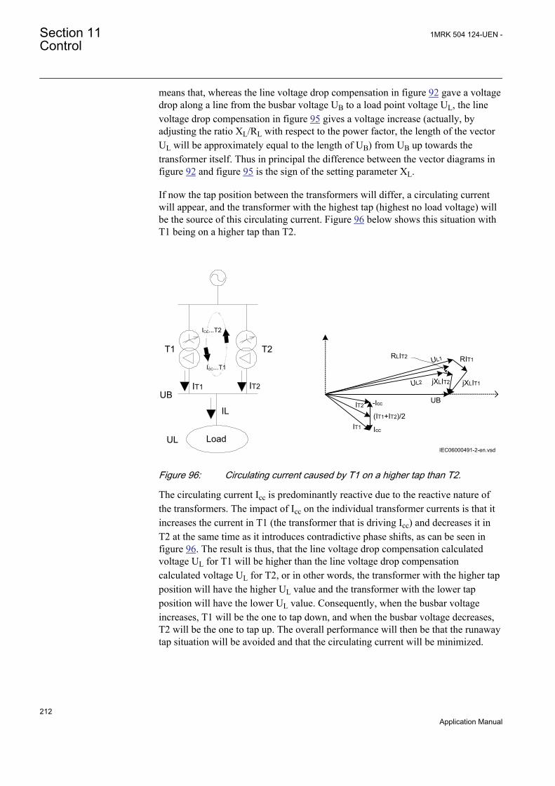
means that, whereas the line voltage drop compensation in figure 92 gave a voltagedrop along a line from the busbar voltage UB to a load point voltage UL, the linevoltage drop compensation in figure 95 gives a voltage increase (actually, byadjusting the ratio XL/RL with respect to the power factor, the length of the vectorUL will be approximately equal to the length of UB) from UB up towards thetransformer itself. Thus in principal the difference between the vector diagrams infigure 92 and figure 95 is the sign of the setting parameter XL.
If now the tap position between the transformers will differ, a circulating currentwill appear, and the transformer with the highest tap (highest no load voltage) willbe the source of this circulating current. Figure 96 below shows this situation withT1 being on a higher tap than T2.
Load
T1 T2
UB
UL
IT1 IT2
UB
UL1 RIT1
jXLIT1
Icc
-Icc
(IT1+IT2)/2IT1
IT2
UL2
RLIT2
jXLIT2
IEC06000491-2-en.vsd
ICC...T2
ICC...T1
IL
IEC06000491 V2 EN
Figure 96: Circulating current caused by T1 on a higher tap than T2.
The circulating current Icc is predominantly reactive due to the reactive nature ofthe transformers. The impact of Icc on the individual transformer currents is that itincreases the current in T1 (the transformer that is driving Icc) and decreases it inT2 at the same time as it introduces contradictive phase shifts, as can be seen infigure 96. The result is thus, that the line voltage drop compensation calculatedvoltage UL for T1 will be higher than the line voltage drop compensationcalculated voltage UL for T2, or in other words, the transformer with the higher tapposition will have the higher UL value and the transformer with the lower tapposition will have the lower UL value. Consequently, when the busbar voltageincreases, T1 will be the one to tap down, and when the busbar voltage decreases,T2 will be the one to tap up. The overall performance will then be that the runawaytap situation will be avoided and that the circulating current will be minimized.
Section 11 1MRK 504 124-UEN -Control
212Application Manual
Parallel control with the circulating current methodTwo transformers with different turns ratio, connected to the same busbar on the HV-side, will apparently show different LV-side voltage. If they are now connected tothe same LV busbar but remain unloaded, this difference in no-load voltage willcause a circulating current to flow through the transformers. When load is put onthe transformers, the circulating current will remain the same, but now it will besuperimposed on the load current in each transformer. Voltage control of paralleltransformers with the circulating current method means minimizing of thecirculating current at a given voltage target value, thereby achieving:
1. that the busbar or load voltage is regulated to a preset target value2. that the load is shared between parallel transformers in proportion to their
ohmic short circuit reactance
If the transformers have equal percentage impedance given in the respectivetransformer MVA base, the load will be divided in direct proportion to the ratedpower of the transformers when the circulating current is minimized.
This method requires extensive exchange of data between the TR8ATCC functionblocks (one TR8ATCC function for each transformer in the parallel group).TR8ATCC function block can either be located in the same IED, where they areconfigured in PCM600 to co-operate, or in different IEDs. If the functions arelocated in different IEDs they must communicate via GOOSE interbaycommunication on the IEC 61850 communication protocol. .
The busbar voltage UB is measured individually for each transformer in the parallelgroup by its associated TR8ATCC function. These measured values will then beexchanged between the transformers, and in each TR8ATCC block, the mean valueof all UB values will be calculated. The resulting value UBmean will then be used ineach IED instead of UB for the voltage regulation, thus assuring that the same valueis used by all TR8ATCC functions, and thereby avoiding that one erroneousmeasurement in one transformer could upset the voltage regulation. At the sametime, supervision of the VT mismatch is also performed. This works such that, if ameasured voltage UB, differs from UBmean with more than a preset value (settingparameter VTmismatch) and for more than a pre set time (setting parametertVTmismatch) an alarm signal VTALARM will be generated.
The calculated mean busbar voltage UBmean is shown on the local HMI as a servicevalue BusVolt under Main menu/Tests/Function status/Control/TR8ATCC (90)/1:TR8ATCC/Outputs.
Measured current values for the individual transformers must be communicatedbetween the participating TR8ATCC functions, in order to calculate the circulatingcurrent.
The calculated circulating current Icc_i for transformer “i” is shown on the HMI asa service value ICIRCUL under Main menu/Control/Commands/TR8ATCC(90)/X:TR8ATCC.
1MRK 504 124-UEN - Section 11Control
213Application Manual
When the circulating current is known, it is possible to calculate a no-load voltagefor each transformer in the parallel group. To do that the magnitude of thecirculating current in each bay, is first converted to a voltage deviation, Udi, withequation 92:
_di i cc i iU C I X= ´ ´
EQUATION1869 V1 EN (Equation 92)
where Xi is the short-circuit reactance for transformer i and Ci, is a settingparameter named Comp which serves the purpose of alternatively increasing ordecreasing the impact of the circulating current in TR8ATCC control calculations.It should be noted that Udi will have positive values for transformers that producecirculating currents and negative values for transformers that receive circulatingcurrents.
Now the magnitude of the no-load voltage for each transformer can beapproximated with:
i Bmean diU U U= +EQUATION1870 V1 EN (Equation 93)
This value for the no-load voltage is then simply put into the voltage controlfunction for single transformer. There it is treated as the measured busbar voltage,and further control actions are taken as described previously in section "Automaticvoltage control for a single transformer". By doing this, the overall control strategycan be summarized as follows.
For the transformer producing/receiving the circulating current, the calculated no-load voltage will be greater/smaller than the measured voltage UBmean. Thecalculated no-load voltage will then be compared with the set voltage USet. Asteady deviation which is outside the outer deadband will result in ULOWER orURAISE being initiated alternatively. In this way the overall control action willalways be correct since the position of a tap changer is directly proportional to thetransformer no-load voltage. The sequence resets when UBmean is inside the innerdeadband at the same time as the calculated no-load voltages for all transformers inthe parallel group are inside the outer deadband.
In parallel operation with the circulating current method, different USet values forindividual transformers can cause the voltage regulation to be unstable. For thisreason, the mean value of USet for parallel operating transformers can beautomatically calculated and used for the voltage regulation. This is set On/Off bysetting parameter OperUsetPar. The calculated mean USet value is shown on thelocal HMI as a service value USETPAR under Main menu/Control/Commands/TR8ATCC (90)/X:TR8ATCC.
The use of mean USet is recommended for parallel operation with the circulatingcurrent method, especially in cases when Load Voltage Adjustment is also used.
Section 11 1MRK 504 124-UEN -Control
214Application Manual
Line voltage drop compensation for parallel controlThe line voltage drop compensation for a single transformer is described in section"Line voltage drop". The same principle is used for parallel control with thecirculating current method and with the master – follower method, except that thetotal load current, IL, is used in the calculation instead of the individual transformercurrent. (See figure 92 for details). The same values for the parameters Rline andXline shall be set in all IEDs in the same parallel group. There is no automaticchange of these parameters due to changes in the substation topology, thus theyshould be changed manually if needed.
Adapt mode, manual control of a parallel group
Adapt mode (operation with the circulating current method)When the circulating current method is used, it is also possible to manually controlthe transformers as a group. To achieve this, the setting OperationAdapt must beset On, then the control mode for one TR8ATCC shall be set to “Manual” via thebinary input MANCTRL or the local HMI under Main menu/Control/Commands/TR8ATCC (90)/1:TR8ATCC whereas the other TR8ATCCs are left in“Automatic”. TR8ATCCs in automatic mode will then observe that onetransformer in the parallel group is in manual mode and will then automatically beset in adapt mode. As the name indicates they will adapt to the manual tapping ofthe transformer that has been put in manual mode.
TR8ATCC in adapt mode will continue the calculation of Udi, but instead ofadding Udi to the measured busbar voltage, it will compare it with the deadbandDU. The following control rules are used:
1. If Udi is positive and its modulus is greater thanDU, then initiate an ULOWERcommand. Tapping will then take place after appropriate t1/t2 timing.
2. If Udi is negative and its modulus is greater than DU, then initiate an URAISEcommand. Tapping will then take place after appropriate t1/t2 timing.
3. If Udi modulus is smaller thanDU, then do nothing.
The binary output signal ADAPT on the TR8ATCC function block will beactivated to indicate that this TR8ATCC is adapting to another TR8ATCC in theparallel group.
It shall be noted that control with adapt mode works as described under thecondition that only one transformer in the parallel group is set to manual mode viathe binary input MANCTRL or, the local HMI Main menu/Control/Commands/TR8ATCC (90)/1:TR8ATCC.
In order to operate each tap changer individually when the circulating currentmethod is used, the operator must set each TR8ATCC in the parallel group, in manual.
Adapt mode (operation with the master follower method)When in master follower mode, the adapt situation occurs when the settingOperationAdapt is On, and the master is put in manual control with the followers
1MRK 504 124-UEN - Section 11Control
215Application Manual

still in parallel master-follower control. In this situation the followers will continueto follow the master the same way as when it is automatic control.
If one follower in a master follower parallel group is put in manual mode, still withthe setting OperationAdaptOn, the rest of the group will continue in automaticmaster follower control. The follower in manual mode will of course disregard anypossible tapping of the master. However, as one transformer in the parallel group isnow exempted from the parallel control, the binary output signal ADAPT onTR8ATCCfunction block will be activated for the rest of the parallel group.
Power monitoringThe level (with sign) of active and reactive power flow through the transformer,can be monitored. This function can be utilized for different purposes for example,to block the voltage control function when active power is flowing from the LVside to the HV side or to initiate switching of reactive power compensation plant,and so on.
There are four setting parameters P>, P<, Q> and Q< with associated outputs inTR8ATCC function blocks PGTFWD, PLTREV, QGTFWD and QLTREV. Whenpassing the pre-set value, the associated output will be activated after the commontime delay setting tPower.
The definition of direction of the power is such that the active power P is forwardwhen power flows from the HV-side to the LV-side as shown in figure 97. Thereactive power Q is forward when the total load on the LV side is inductive( reactance) as shown in figure 97.
ATCC
IED
HV-side
Pforward
LV-sideIEC06000536_1_en.vsd
Qforward (inductive)
IEC06000536 V2 EN
Figure 97: Power direction references
With the four outputs in the function block available, it is possible to do more thanjust supervise a level of power flow in one direction. By combining the outputswith logical elements in ACT tool, it is also possible to cover for example, intervalsas well as areas in the P-Q plane.
Section 11 1MRK 504 124-UEN -Control
216Application Manual
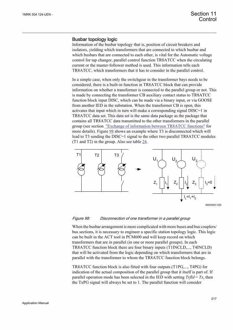
Busbar topology logicInformation of the busbar topology that is, position of circuit breakers andisolators, yielding which transformers that are connected to which busbar andwhich busbars that are connected to each other, is vital for the Automatic voltagecontrol for tap changer, parallel control function TR8ATCC when the circulatingcurrent or the master-follower method is used. This information tells eachTR8ATCC, which transformers that it has to consider in the parallel control.
In a simple case, when only the switchgear in the transformer bays needs to beconsidered, there is a built-in function in TR8ATCC block that can provideinformation on whether a transformer is connected to the parallel group or not. Thisis made by connecting the transformer CB auxiliary contact status to TR8ATCCfunction block input DISC, which can be made via a binary input, or via GOOSEfrom another IED in the substation. When the transformer CB is open, thisactivates that input which in turn will make a corresponding signal DISC=1 inTR8ATCC data set. This data set is the same data package as the package thatcontains all TR8ATCC data transmitted to the other transformers in the parallelgroup (see section "Exchange of information between TR8ATCC functions" formore details). Figure 98 shows an example where T3 is disconnected which willlead to T3 sending the DISC=1 signal to the other two parallel TR8ATCC modules(T1 and T2) in the group. Also see table 24.
T1 T2 T3
99000952.VSD
U1 U2 U3
Z1 Z2 Z3I1 I2 I3=0
IL=I1+I2
IEC99000952 V1 EN
Figure 98: Disconnection of one transformer in a parallel group
When the busbar arrangement is more complicated with more buses and bus couplers/bus sections, it is necessary to engineer a specific station topology logic. This logiccan be built in the ACT tool in PCM600 and will keep record on whichtransformers that are in parallel (in one or more parallel groups). In eachTR8ATCC function block there are four binary inputs (T1INCLD,..., T4INCLD)that will be activated from the logic depending on which transformers that are inparallel with the transformer to whom the TR8ATCC function block belongs.
TR8ATCC function block is also fitted with four outputs (T1PG,..., T4PG) forindication of the actual composition of the parallel group that it itself is part of. Ifparallel operation mode has been selected in the IED with setting TrfId = Tx, thenthe TxPG signal will always be set to 1. The parallel function will consider
1MRK 504 124-UEN - Section 11Control
217Application Manual
communication messages only from the voltage control functions working inparallel (according to the current station configuration). When the parallel voltagecontrol function detects that no other transformers work in parallel it will behave asa single voltage control function in automatic mode.
Exchange of information between TR8ATCC functionsEach transformer in a parallel group needs an Automatic voltage control for tapchanger, parallel control TR8ATCC function block of its own for the parallelvoltage control. Communication between these TR8ATCCs is made either on theGOOSE interbay communication on the IEC 61850 protocol if TR8ATCCfunctions reside in different IEDs, or alternatively configured internally in one IEDif multiple instances of TR8ATCC reside in the same IED. Complete exchange ofTR8ATCC data, analog as well as binary, on GOOSE is made cyclically every 300ms.
TR8ATCC function block has an output ATCCOUT. This output contains two setsof signals. One is the data set that needs to be transmitted to other TR8ATCCblocks in the same parallel group, and the other is the data set that is transferred tothe TCMYLTC function block for the same transformer as TR8ATCC blockbelongs to.
There are 10 binary signals and 6 analog signals in the data set that is transmittedfrom one TR8ATCC block to the other TR8ATCC blocks in the same parallel group:
Table 22: Binary signals
Signal ExplanationTimerOn This signal is activated by the transformer that has started its timer and is
going to tap when the set time has expired.
automaticCTRL Activated when the transformer is set in automatic control
mutualBlock Activated when the automatic control is blocked
disc Activated when the transformer is disconnected from the busbar
receiveStat Signal used for the horizontal communication
TermIsForcedMaster Activated when the transformer is selected Master in the master-followerparallel control mode
TermIsMaster Activated for the transformer that is master in the master-follower parallelcontrol mode
termReadyForMSF Activated when the transformer is ready for master-follower parallel controlmode
raiseVoltageOut Order from the master to the followers to tap up
lowerVoltageOut Order from the master to the followers to tap down
Table 23: Analog signals
Signal ExplanationvoltageBusbar Measured busbar voltage for this transformer
ownLoadCurrim Measured load current imaginary part for this transformer
ownLoadCurrre Measured load current real part for this transformer
Table continues on next page
Section 11 1MRK 504 124-UEN -Control
218Application Manual

Signal ExplanationreacSec Transformer reactance in primary ohms referred to the LV side
relativePosition The transformer's actual tap position
voltage Setpoint The transformer's set voltage (USet) for automatic control
Manual configuration of VCTR GOOSE data set is required. Notethat both data value attributes and quality attributes have to bemapped. The following data objects must be configured:
• BusV• LodAIm• LodARe• PosRel• SetV• VCTRStatus• X2
The transformers controlled in parallel with the circulating current method or themaster-follower method must be assigned unique identities. These identities areentered as a setting in each TR8ATCC, and they are predefined as T1, T2, T3,T4( transformers 1 to 4). In figure 98 there are three transformers with the parameterTrfId set to T1, T2 and T3, respectively.
For parallel control with the circulating current method or the master-followermethod alternatively, the same type of data set as described above, must beexchanged between two TR8ATCC. To achieve this, each TR8ATCC istransmitting its own data set on the output ATCCOUT as previously mentioned. Toreceive data from the other transformers in the parallel group, the outputATCCOUT from each transformer must be connected (via GOOSE or internally inthe application configuration) to the inputs HORIZx (x = identifier for the othertransformers in the parallel group) on TR8ATCC function block. Apart from this,there is also a setting in each TR8ATCC T1RXOP=Off/On,..., T4RXOP=Off/ On.This setting determines from which of the other transformer individuals that datashall be received. Settings in the three TR8ATCC blocks for the transformers infigure 98, would then be according to the table 24:
Table 24: Setting of TxRXOP
TrfId=T1 T1RXOP=Off T2RXOP=On T3RXOP=On T4RXOP=Off
TrfId=T2 T1RXOP=On T2RXOP=Off T3RXOP=On T4RXOP=Off
TrfId=T3 T1RXOP=On T2RXOP=On T3RXOP=Off T4RXOP=Off
Observe that this parameter must be set to Off for the “own” transformer. (fortransformer with identity T1 parameter T1RXOP must be set to Off, and so on.
Blocking
1MRK 504 124-UEN - Section 11Control
219Application Manual
Blocking conditionsThe purpose of blocking is to prevent the tap changer from operating underconditions that can damage it, or otherwise when the conditions are such thatpower system related limits would be exceeded or when, for example theconditions for automatic control are not met.
For the Automatic voltage control for tap changer function, TR8ATCC for parallelcontrol, three types of blocking are used:
Partial Block: Prevents operation of the tap changer only in one direction (onlyURAISE or ULOWER command is blocked) in manual and automatic control mode.
Auto Block: Prevents automatic voltage regulation, but the tap changer can still becontrolled manually.
Total Block: Prevents any tap changer operation independently of the controlmode (automatic as well as manual).
Setting parameters for blocking that can be set in TR8ATCC under general settingsin local HMI are listed in table 25.
Table 25: Blocking settings
Setting Values (Range) DescriptionOCBk(automaticallyreset)
AlarmAuto BlockAuto&Man Block
When any one of the three HV currents exceeds thepreset value IBlock, TR8ATCC will be temporarily totallyblocked. The outputs IBLK and TOTBLK or AUTOBLK willbe activated depending on the actual parameter setting.
OVPartBk(automaticallyreset)
AlarmAuto&Man Block
If the busbar voltage UB (not the compensated load pointvoltage UL) exceeds Umax (see figure 90, further URAISEcommands will be blocked if the value Auto&Man Block isselected. If permitted by setting, a fast step down actionwill be initiated in order to re-enter into the range Umin <UB < Umax. The Fast Step down function can be setactive for automatic control or automatic as well asmanual control and it is blocked when the lowest voltagetap position is reached. The time delay for the fast stepdown function is separately set. The output UHIGH will beactivated as long as the voltage is above Umax.
UVPartBk(automaticallyreset)
AlarmAuto&Man Block
If the busbar voltage UB (not the calculated load pointvoltage UL) is between Ublock and Umin (see figure 90),further ULOWER commands will be blockedindependently of the control mode when the valueAuto&Man Block is selected. The output ULOW will be set.
UVBk(automaticallyreset)
AlarmAuto BlockAuto&Man Block
If the busbar voltage UB falls below Ublock this blockingcondition is active. It is recommended to block automaticcontrol in this situation and allow manual control. This isbecause the situation normally would correspond to adisconnected transformer and then it should be allowed tooperate the tap changer before reconnecting thetransformer. The outputs UBLK and TOTBLK orAUTOBLK will be activated depending on the actualparameter setting.
Table continues on next page
Section 11 1MRK 504 124-UEN -Control
220Application Manual
Setting Values (Range) DescriptionCmdErrBk(manually reset)
AlarmAuto BlockAuto&Man Block
Typical operating time for a tap changer mechanism isaround 3-8 seconds. Therefore, the function should waitfor a position change before a new command is issued.The command error signal, CMDERRAL on theTCMYLTC function block, will be set if the tap changerposition does not change one step in the correct directionwithin the time given by the setting tTCTimeout inTCMYLTC function block. The tap changer moduleTCMYLTC will then indicate the error until a successfulcommand has been carried out or it has been reset bychanging control mode of TR8ATCC function to Manualand then back to Automatic. The outputs CMDERRAL onTCMYLTC and TOTBLK or AUTOBLK on TR8ATCC willbe activated depending on the actual parameter setting.This error condition can be reset by the input RESETERRon TCMYLTC function block, or alternatively by changingcontrol mode of TR8ATCC function to Manual and thenback to Automatic.
TapChgBk(manually reset
AlarmAuto BlockAuto&Man Block
If the input TCINPROG of TCMYLTC function block isconnected to the tap changer mechanism, then thisblocking condition will be active if the TCINPROG inputhas not reset when the tTCTimeout timer has timed out.The output TCERRAL will be activated depending on theactual parameter setting. In correct operation theTCINPROG shall appear during the URAISE/ULOWERoutput pulse and disappear before the tTCTimeout timehas elapsed.This error condition can be reset by the input RESETERRon TCMYLTC function block, or alternatively by changingcontrol mode of TR8ATCC function to Manual and thenback to Automatic.
Table continues on next page
1MRK 504 124-UEN - Section 11Control
221Application Manual
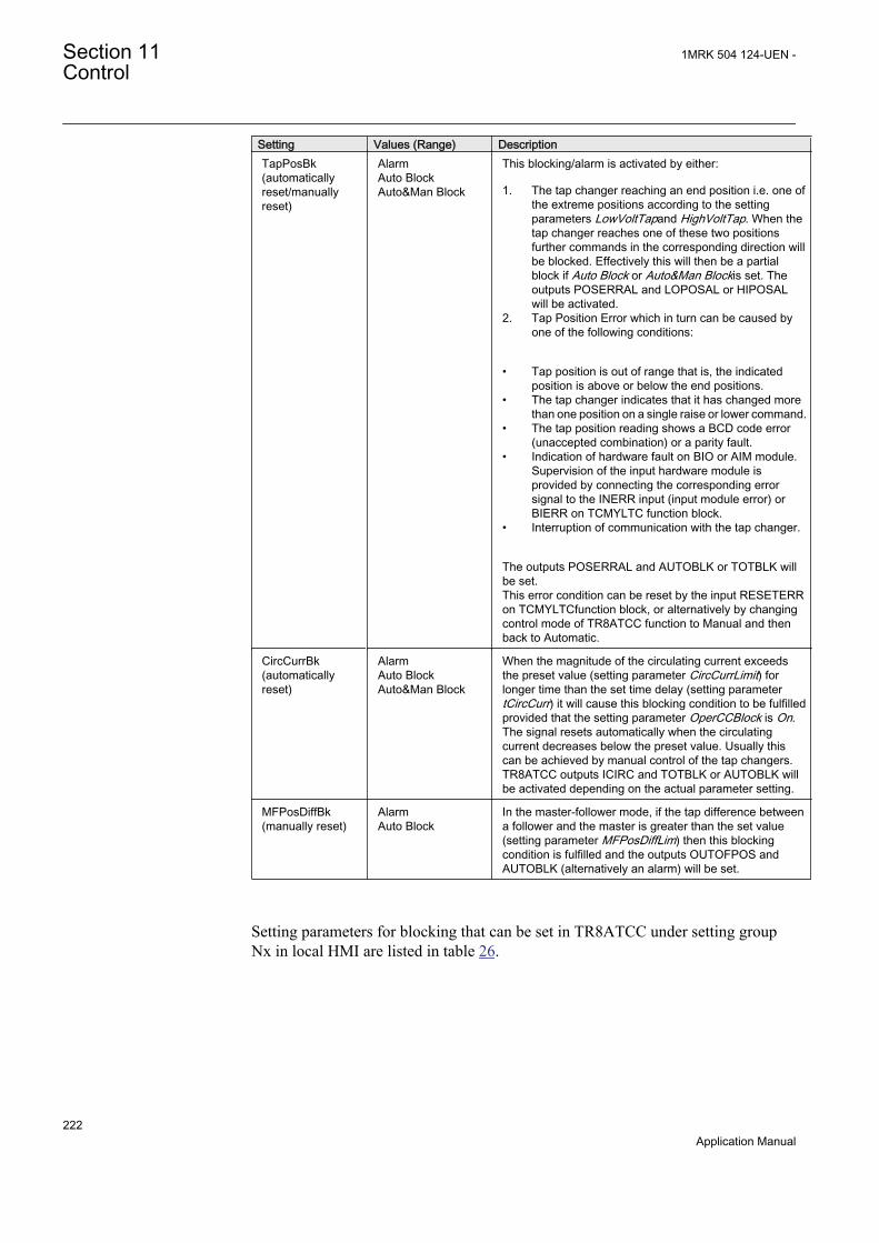
Setting Values (Range) DescriptionTapPosBk(automaticallyreset/manuallyreset)
AlarmAuto BlockAuto&Man Block
This blocking/alarm is activated by either:
1. The tap changer reaching an end position i.e. one ofthe extreme positions according to the settingparameters LowVoltTapand HighVoltTap. When thetap changer reaches one of these two positionsfurther commands in the corresponding direction willbe blocked. Effectively this will then be a partialblock if Auto Block or Auto&Man Blockis set. Theoutputs POSERRAL and LOPOSAL or HIPOSALwill be activated.
2. Tap Position Error which in turn can be caused byone of the following conditions:
• Tap position is out of range that is, the indicatedposition is above or below the end positions.
• The tap changer indicates that it has changed morethan one position on a single raise or lower command.
• The tap position reading shows a BCD code error(unaccepted combination) or a parity fault.
• Indication of hardware fault on BIO or AIM module.Supervision of the input hardware module isprovided by connecting the corresponding errorsignal to the INERR input (input module error) orBIERR on TCMYLTC function block.
• Interruption of communication with the tap changer.
The outputs POSERRAL and AUTOBLK or TOTBLK willbe set.This error condition can be reset by the input RESETERRon TCMYLTCfunction block, or alternatively by changingcontrol mode of TR8ATCC function to Manual and thenback to Automatic.
CircCurrBk(automaticallyreset)
AlarmAuto BlockAuto&Man Block
When the magnitude of the circulating current exceedsthe preset value (setting parameter CircCurrLimit) forlonger time than the set time delay (setting parametertCircCurr) it will cause this blocking condition to be fulfilledprovided that the setting parameter OperCCBlock is On.The signal resets automatically when the circulatingcurrent decreases below the preset value. Usually thiscan be achieved by manual control of the tap changers.TR8ATCC outputs ICIRC and TOTBLK or AUTOBLK willbe activated depending on the actual parameter setting.
MFPosDiffBk(manually reset)
AlarmAuto Block
In the master-follower mode, if the tap difference betweena follower and the master is greater than the set value(setting parameter MFPosDiffLim) then this blockingcondition is fulfilled and the outputs OUTOFPOS andAUTOBLK (alternatively an alarm) will be set.
Setting parameters for blocking that can be set in TR8ATCC under setting groupNx in local HMI are listed in table 26.
Section 11 1MRK 504 124-UEN -Control
222Application Manual

Table 26: Blocking settings
Setting Value (Range) DescriptionTotalBlock (manually reset) On/Off TR8ATCC function can be totally
blocked via the settingparameter TotalBlock, which canbe set On/Off from the localHMI . The output TOTBLK willbe activated.
AutoBlock (manually reset) On/Off TR8ATCC function can beblocked for automatic control viathe setting parameter AutoBlock,which can be set On/Off fromthe local HMI . The outputAUTOBLK will be set.
TR8ATCC blockings that can be made via input signals in the function block arelisted in table 27.
Table 27: Blocking via binary inputs
Input name Activation DescriptionBLOCK (manually reset) On/Off(via binary input) The voltage control function can
be totally blocked via the binaryinput BLOCK on TR8ATCCfunction block. The outputTOTBLK will be activated.
EAUTOBLK (manually reset) On/Off (via binary input) The voltage control function canbe blocked for automatic controlvia the binary input EAUTOBLKon TR8ATCC function block.The output AUTOBLK will beactivated. Deblocking is madevia the input DEBLKAUT.
Blockings activated by the operating conditions and there are no setting or separateexternal activation possibilities are listed in table 28.
1MRK 504 124-UEN - Section 11Control
223Application Manual
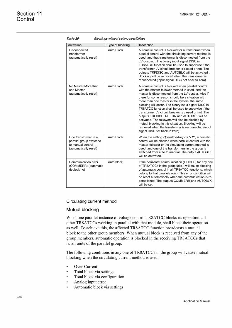
Table 28: Blockings without setting possibilities
Activation Type of blocking DescriptionDisconnectedtransformer(automatically reset)
Auto Block Automatic control is blocked for a transformer whenparallel control with the circulating current method isused, and that transformer is disconnected from theLV-busbar. . The binary input signal DISC inTR8ATCC function shall be used to supervise if thetransformer LV circuit breaker is closed or not. Theoutputs TRFDISC and AUTOBLK will be activated .Blocking will be removed when the transformer isreconnected (input signal DISC set back to zero).
No Master/More thanone Master(automatically reset)
Auto Block Automatic control is blocked when parallel controlwith the master-follower method is used, and themaster is disconnected from the LV-busbar. Also ifthere for some reason should be a situation withmore than one master in the system, the sameblocking will occur. The binary input signal DISC inTR8ATCC function shall be used to supervise if thetransformer LV circuit breaker is closed or not. Theoutputs TRFDISC, MFERR and AUTOBLK will beactivated. The followers will also be blocked bymutual blocking in this situation. Blocking will beremoved when the transformer is reconnected (inputsignal DISC set back to zero).
One transformer in aparallel group switchedto manual control(automatically reset)
Auto Block When the setting OperationAdapt is “Off”, automaticcontrol will be blocked when parallel control with themaster-follower or the circulating current method isused, and one of the transformers in the group isswitched from auto to manual. The output AUTOBLKwill be activated.
Communication error(COMMERR) (automaticdeblocking)
Auto block If the horizontal communication (GOOSE) for any oneof TR8ATCCs in the group fails it will cause blockingof automatic control in all TR8ATCC functions, whichbelong to that parallel group. This error condition willbe reset automatically when the communication is re-established. The outputs COMMERR and AUTOBLKwill be set.
Circulating current method
Mutual blockingWhen one parallel instance of voltage control TR8ATCC blocks its operation, allother TR8ATCCs working in parallel with that module, shall block their operationas well. To achieve this, the affected TR8ATCC function broadcasts a mutualblock to the other group members. When mutual block is received from any of thegroup members, automatic operation is blocked in the receiving TR8ATCCs thatis, all units of the parallel group.
The following conditions in any one of TR8ATCCs in the group will cause mutualblocking when the circulating current method is used:
• Over-Current• Total block via settings• Total block via configuration• Analog input error• Automatic block via settings
Section 11 1MRK 504 124-UEN -Control
224Application Manual
• Automatic block via configuration• Under-Voltage• Command error• Position indication error• Tap changer error• Circulating current• Communication error
Master-follower methodWhen the master is blocked, the followers will not tap by themselves and there isconsequently no need for further mutual blocking. On the other hand, when afollower is blocked there is a need to send a mutual blocking signal to the master.This will prevent a situation where the rest of the group otherwise would be able totap away from the blocked individual, and that way cause high circulating currents.
Thus, when a follower is blocked, it broadcasts a mutual block on the horizontalcommunication. The master picks up this message, and blocks its automaticoperation as well.
Besides the conditions listed above for mutual blocking with the circulating currentmethod, the following blocking conditions in any of the followers will also causemutual blocking:
• Master-follower out of position• Master-follower error (No master/More than one master)
GeneralIt should be noted that partial blocking will not cause mutual blocking.
TR8ATCC, which is the “source” of the mutual blocking will set its AUTOBLKoutput as well as the output which corresponds to the actual blocking condition forexample, IBLK for over-current blocking. The other TR8ATCCs that receive amutual block signal will only set its AUTOBLK output.
The mutual blocking remains until TR8ATCC that dispatched the mutual blocksignal is de-blocked. Another way to release the mutual blocking is to forceTR8ATCC, which caused mutual blocking to Single mode operation. This is doneby activating the binary input SNGLMODE on TR8ATCC function block or bysetting the parameter OperationPAR to Off from the built-in local HMI .
TR8ATCC function can be forced to single mode at any time. It will then behaveexactly the same way as described in section "Automatic voltage control for asingle transformer", except that horizontal communication messages are still sentand received, but the received messages are ignored. TR8ATCC is at the same timealso automatically excluded from the parallel group.
Disabling of blockings in special situations
1MRK 504 124-UEN - Section 11Control
225Application Manual
When the Automatic voltage control for tap changer TR8ATCC for parallelcontrol, function block is connected to read back information (tap position valueand tap changer in progress signal) it may sometimes be difficult to find timingdata to be set in TR8ATCC for proper operation. Especially at commissioning offor example, older transformers the sensors can be worn and the contacts maybebouncing etc. Before the right timing data is set it may then happen that TR8ATCCbecomes totally blocked or blocked in auto mode because of incorrect settings. Inthis situation, it is recommended to temporarily set these types of blockings toalarm instead until the commissioning of all main items are working as expected.
Hunting detectionHunting detection is provided in order to generate an alarm when the voltagecontrol gives an abnormal number of commands or abnormal sequence ofcommands within a pre-defined period of time.
There are three hunting functions:
1. The Automatic voltage control for tap changer function, TR8ATCC forparallel control will activate the output signal DAYHUNT when the number oftap changer operations exceed the number given by the setting DayHuntDetectduring the last 24 hours (sliding window). Active as well in manual as inautomatic mode.
2. TR8ATCC function will activate the output signal HOURHUNT when thenumber of tap changer operations exceed the number given by the settingHourHuntDetect during the last hour (sliding window). Active as well inmanual as in automatic mode.
3. TR8ATCC function will activate the output signal HUNTING when the totalnumber of contradictory tap changer operations (RAISE, LOWER, RAISE,LOWER, and so on) exceeds the pre-set value given by the settingNoOpWindow within the time sliding window specified via the settingparameter tWindowHunt. Only active in automatic mode.
Hunting can be the result of a narrow deadband setting or some other abnormalitiesin the control system.
Wearing of the tap changer contactsTwo counters, ContactLife and NoOfOperations are available within the Tapchanger control and supervision function, 6 binary inputs TCMYLTC. They can beused as a guide for maintenance of the tap changer mechanism. The ContactLifecounter represents the remaining number of operations (decremental counter) atrated load.
ContactLife ContactLifen+1 n Irated
Iloada
æ ö= - ç ÷ç ÷
è øEQUATION1873 V2 EN (Equation 94)
Section 11 1MRK 504 124-UEN -Control
226Application Manual

where n is the number of operations and α is an adjustable setting parameter,CLFactor, with default value is set to 2. With this default setting an operation atrated load (current measured on HV-side) decrements the ContactLife counter with1.
The NoOfOperations counter simply counts the total number of operations(incremental counter).
Both counters are stored in a non-volatile memory as well as, the times and dates oftheir last reset. These dates are stored automatically when the command to reset thecounter is issued. It is therefore necessary to check that the IED internal time iscorrect before these counters are reset. The counter value can be reset on the localHMI under Main menu/Clear/Clear counters/TCMLYTC (84)/n:TCMYLTC/ContLifeCounter
Both counters and their last reset dates are shown on the local HMI as servicevalues CLCNT_VAL and CNT_VAL under Main menu/Tests/Function status/Control/TCMYLTC (84)/n:TCMYLTC/Outputs/CLCNT_VAL and Mainmenu/Tests/Function status/Control/TCMYLTC (84)/n:TCMYLTC/Outputs/CNT_VAL
11.2.3 Setting guidelines
11.2.3.1 TR8ATCC general settings
Base IED values for primary current (setting IBase), primary voltage (settingUBase) and primary power (setting SBase) for a particular winding are set in aGlobal base values for settings function GBASVAL. Settings GlobalBaseSel1 andGlobalBaseSel2 are used to select the corresponding GBASVAL function forreference of base values.
TrfId: The transformer identity is used to identify transformer individuals in aparallel group. Thus, transformers that can be part of the same parallel group musthave unique identities. Moreover, all transformers that communicate over the samehorizontal communication (GOOSE) must have unique identities.
Xr2: The reactance of the transformer in primary ohms referred to the LV side.
tAutoMSF: Time delay set in a follower for execution of a raise or lower commandgiven from a master. This feature can be used when a parallel group is controlled inthe master-follower mode, follow tap, and it is individually set for each follower,which means that different time delays can be used in the different followers inorder to avoid simultaneous tapping if this is wanted. It shall be observed that it isnot applicable in the follow command mode.
OperationAdapt: This setting enables or disables adapt mode for parallel controlwith the circulating current method or the master-follower method.
MFMode: Selection of Follow Command or Follow Tap in the master-follower mode.
1MRK 504 124-UEN - Section 11Control
227Application Manual
CircCurrBk: Selection of action to be taken in case the circulating current exceedsCircCurrLimit.
CmdErrBk: Selection of action to be taken in case the feedback from the tapchanger has resulted in command error.
OCBk: Selection of action to be taken in case any of the three phase currents on theHV-side has exceeded Iblock.
MFPosDiffBk: Selection of action to be taken in case the tap difference between afollower and the master is greater than MFPosDiffLim.
OVPartBk: Selection of action to be taken in case the busbar voltage UB exceedsUmax.
TapChgBk: Selection of action to be taken in case a Tap Changer Error has beenidentified.
TapPosBk: Selection of action to be taken in case of Tap Position Error, or if thetap changer has reached an end position.
UVBk: Selection of action to be taken in case the busbar voltage UB falls belowUblock.
UVPartBk: Selection of action to be taken in case the busbar voltage UB is betweenUblock and Umin.
11.2.3.2 TR8ATCC Setting group
GeneralOperation: Switching automatic voltage control for tap changer, TR8ATCCfunction On/Off.
MeasMode: Selection of single phase, or phase-phase, or positive sequencequantity to be used for voltage and current measurement on the LV-side. Theinvolved phases are also selected. Thus, single phase as well as phase-phase or three-phase feeding on the LV-side is possible but it is commonly selected for currentand voltage.
TotalBlock: When this setting is On, TR8ATCC function that is, the voltage controlis totally blocked for manual as well as automatic control.
AutoBlock: When this setting is On, TR8ATCC function that is, the voltage controlis blocked for automatic control.
OperationFSDMode: This setting enables/disables the fast step down function. Enabling canbe for automatic and manual control, or for only automatic control alternatively.
tFSD: Time delay to be used for the fast step down tapping.
Section 11 1MRK 504 124-UEN -Control
228Application Manual
VoltageUSet: Setting value for the target voltage, to be set in per cent of UBase.
UDeadband: Setting value for one half of the outer deadband, to be set in per centof UBase. The deadband is symmetrical around USet, see section "Automaticvoltage control for a single transformer", figure 90. In that figure UDeadband isequal to DU. The setting is normally selected to a value near the powertransformer’s tap changer voltage step (typically 75 - 125% of the tap changer step).
UDeadbandInner: Setting value for one half of the inner deadband, to be set in percent of UBase. The inner deadband is symmetrical around USet, see section"Automatic voltage control for a single transformer",figure 90. In that figureUDeadbandInner is equal to DUin. The setting shall be smaller than UDeadband.Typically the inner deadband can be set to 25-70% of the UDeadband value.
Umax: This setting gives the upper limit of permitted busbar voltage (see section"Automatic voltage control for a single transformer", figure 90). It is set in per centof UBase. If OVPartBk is set to Auto&ManBlock, then busbar voltages aboveUmax will result in a partial blocking such that only lower commands are permitted.
Umin This setting gives the lower limit of permitted busbar voltage (see section"Automatic voltage control for a single transformer", figure 90). It is set in per centof UBase. If UVPartBk is set to Auto&ManBlock, then busbar voltages belowUmin will result in a partial blocking such that only raise commands are permitted.
Ublock: Voltages below Ublock normally correspond to a disconnected transformerand therefore it is recommended to block automatic control for this condition(setting UVBk). Ublock is set in per cent of UBase.
Timet1Use: Selection of time characteristic (definite or inverse) for t1.
t1: Time delay for the initial (first) raise/lower command.
t2Use: Selection of time characteristic (definite or inverse) for t2.
t2: Time delay for consecutive raise/lower commands. In the circulating currentmethod, the second, third, etc. commands are all executed with time delay t2independently of which transformer in the parallel group that is tapping. In the master-follower method with the follow tap option, the master is executing the second,third, etc. commands with time delay t2. The followers on the other hand read themaster’s tap position, and adapt to that with the additional time delay given by thesetting tAutoMSF and set individually for each follower.
tMin: The minimum operate time when inverse time characteristic is used (seesection "Time characteristic", figure 91).
Line voltage drop compensation (LDC)OpertionLDC: Sets the line voltage drop compensation function On/Off.
1MRK 504 124-UEN - Section 11Control
229Application Manual
OperCapaLDC: This setting, if set On, will permit the load point voltage to begreater than the busbar voltage when line voltage drop compensation is used. Thatsituation can be caused by a capacitive load. When the line voltage dropcompensation function is used for parallel control with the reverse reactancemethod, then OperCapaLDC must always be set On.
Rline and Xline: For line voltage drop compensation, these settings give the lineresistance and reactance from the station busbar to the load point. The settings forRline and Xline are given in primary system ohms. If more than one line isconnected to the LV busbar, equivalent Rline and Xline values should becalculated and given as settings.
When the line voltage drop compensation function is used for parallel control withthe reverse reactance method, then the compensated voltage which is designated“load point voltage” UL is effectively an increase in voltage up into thetransformer. To achieve this voltage increase, Xline must be negative. Thesensitivity of the parallel voltage regulation is given by the magnitude of Rline andXline settings, with Rline being important in order to get a correct control of thebusbar voltage. This can be realized in the following way. Figure 92 shows thevector diagram for a transformer controlled in a parallel group with the reversereactance method and with no circulation (for example, assume two equaltransformers on the same tap position). The load current lags the busbar voltage UBwith the power factor j and the argument of the impedance Rline and Xline isdesignated j1.
Load voltage adjustment (LVA)LVAConst1: Setting of the first load voltage adjustment value. This adjustment ofthe target value USet is given in percent of UBase.
LVAConst2: Setting of the second load voltage adjustment value. This adjustmentof the target value USet is given in percent ofUBase.
LVAConst3: Setting of the third load voltage adjustment value. This adjustment ofthe target value USet is given in percent of UBase.
LVAConst4: Setting of the fourth load voltage adjustment value. This adjustment ofthe target value USet is given in percent of UBase.
VRAuto: Setting of the automatic load voltage adjustment. This adjustment of thetarget valueUSet is given in percent of UBase, and it is proportional to the loadcurrent with the set value reached at the nominal current IBase (for winding 2which is defined in a global base function, selected with setting GlobalBaseSel2forTR8ATCC).
Tap changer control (TCCtrl)Iblock: Current setting of the over current blocking function. In case, thetransformer is carrying a current exceeding the rated current of the tap changer forexample, because of an external fault. The tap changer operations shall be
Section 11 1MRK 504 124-UEN -Control
230Application Manual
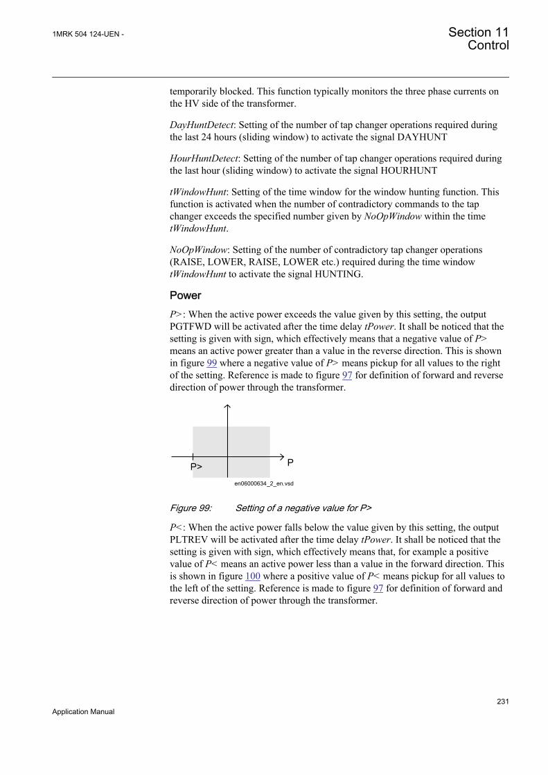
temporarily blocked. This function typically monitors the three phase currents onthe HV side of the transformer.
DayHuntDetect: Setting of the number of tap changer operations required duringthe last 24 hours (sliding window) to activate the signal DAYHUNT
HourHuntDetect: Setting of the number of tap changer operations required duringthe last hour (sliding window) to activate the signal HOURHUNT
tWindowHunt: Setting of the time window for the window hunting function. Thisfunction is activated when the number of contradictory commands to the tapchanger exceeds the specified number given by NoOpWindow within the timetWindowHunt.
NoOpWindow: Setting of the number of contradictory tap changer operations(RAISE, LOWER, RAISE, LOWER etc.) required during the time windowtWindowHunt to activate the signal HUNTING.
PowerP>: When the active power exceeds the value given by this setting, the outputPGTFWD will be activated after the time delay tPower. It shall be noticed that thesetting is given with sign, which effectively means that a negative value of P>means an active power greater than a value in the reverse direction. This is shownin figure 99 where a negative value of P> means pickup for all values to the rightof the setting. Reference is made to figure 97 for definition of forward and reversedirection of power through the transformer.
en06000634_2_en.vsd
PP>
IEC06000634 V2 EN
Figure 99: Setting of a negative value for P>
P<: When the active power falls below the value given by this setting, the outputPLTREV will be activated after the time delay tPower. It shall be noticed that thesetting is given with sign, which effectively means that, for example a positivevalue of P< means an active power less than a value in the forward direction. Thisis shown in figure 100 where a positive value of P< means pickup for all values tothe left of the setting. Reference is made to figure 97 for definition of forward andreverse direction of power through the transformer.
1MRK 504 124-UEN - Section 11Control
231Application Manual

en06000635_2_en.vsd
PP<
IEC06000635 V2 EN
Figure 100: Setting of a positive value for P<
Q>: When the reactive power exceeds the value given by this setting, the outputQGTFWD will be activated after the time delay tPower. It shall be noticed that thesetting is given with sign, which effectively means that the function picks up for allvalues of reactive power greater than the set value, similar to the functionality forP>.
Q<: When the reactive power in reverse direction falls below the value given bythis setting, the output QLTREV will be activated after the time delay tPower. Itshall be noticed that the setting is given with sign, which effectively means that thefunction picks up for all values of reactive power less than the set value, similar tothe functionality for P<.
tPower: Time delay for activation of the power monitoring output signals(PGTFWD, PLTREV, QGTFWD and QLTREV).
Parallel control (ParCtrl)OperationPAR: Setting of the method for parallel operation.
OperCCBlock: This setting enables/disables blocking if the circulating currentexceeds CircCurrLimit.
CircCurrLimit: Pick up value for the circulating current blocking function. Thesetting is made in percent of IBase (for winding 2 which is defined in a global basefunction, selected with setting GlobalBaseSel2 for TR8ATCC).
tCircCurr: Time delay for the circulating current blocking function.
Comp: When parallel operation with the circulating current method is used, thissetting increases or decreases the influence of the circulating current on the regulation.
If the transformers are connected to the same bus on the HV- as well as the LV-side, Comp can be calculated with the following formula which is valid for anynumber of two-winding transformers in parallel, irrespective if the transformers areof different size and short circuit impedance.
2 UComp a 100%n p´D
= ´ ´´
EQUATION1941 V1 EN (Equation 95)
Section 11 1MRK 504 124-UEN -Control
232Application Manual

where:
• DU is the deadband setting in percent.
• n denotes the desired number of difference in tap position between thetransformers, that shall give a voltage deviation Udi which corresponds to thedead-band setting.
• p is the tap step (in % of transformer nominal voltage).
• a is a safety margin that shall cover component tolerances and other non-linearmeasurements at different tap positions (for example, transformer reactanceschanges from rated value at the ends of the regulation range). In most cases avalue of a = 1.25 serves well.
This calculation gives a setting of Comp that will always initiate an action (starttimer) when the transformers have n tap positions difference.
OperSimTap: Enabling/disabling the functionality to allow only one transformer ata time to execute a Lower/Raise command. This setting is applicable only to thecirculating current method, and when enabled, consecutive tappings of the nexttransformer (if required) will be separated with the time delay t2.
OperUsetPar: Enables/disables the use of a common setting for the target voltageUSet. This setting is applicable only to the circulating current method, and whenenabled, a mean value of the USet values for the transformers in the same parallelgroup will be calculated and used.
VTmismatch: Setting of the level for activation of the output VTALARM in casethe voltage measurement in one transformer bay deviates to the mean value of allvoltage measurements in the parallel group.
tVTmismatch: Time delay for activation of the output VTALARM.
T1RXOP.......T4RXOP: This setting is set Onfor every transformer that canparticipate in a parallel group with the transformer in case. For this transformer(own transformer), the setting must always be Off.
TapPosOffs: This setting gives the tap position offset in relation to the master sothat the follower can follow the master’s tap position including this offset.Applicable when regulating in the follow tap command mode.
MFPosDiffLim: When the difference (including a possible offset according toTapPosOffs) between a follower and the master reaches the value in this setting,then the output OUTOFPOS in the Automatic voltage control for tap changer,parallel control TR8ATCC function block of the follower will be activated after thetime delay tMFPosDiff.
tMFPosDiff: Time delay for activation of the output OUTOFPOS.
1MRK 504 124-UEN - Section 11Control
233Application Manual
Transformer nameINSTNAME: This setting can be used for indicating in tools and the local HMI towhich transformer a certain instance of the function belongs.
11.2.3.3 TCMYLTC general settings
Base IED values for primary current (setting IBase), primary voltage (settingUBase) and primary power (setting SBase) for a particular winding are set in aGlobal base values for settings function GBASVAL. Settings GlobalBaseSel1 andGlobalBaseSel2 are used to select the corresponding GBASVAL function forreference of base values.
LowVoltTap: This gives the tap position for the lowest LV-voltage.
HighVoltTap: This gives the tap position for the highest LV-voltage.
CodeType: This setting gives the method of tap position reading.
UseParity: Sets the parity check On/Off for tap position reading when this is madeby Binary, BCD, or Gray code.
tStable: This is the time that needs to elapse after a new tap position has beenreported to TCMYLTC until it is accepted.
CLFactor: This is the factor designated “a” in equation 95. When a tap changeroperates at nominal load current(current measured on the HV-side), theContactLife counter decrements with 1, irrespective of the setting of CLFactor.The setting of this factor gives the weighting of the deviation with respect to theload current.
InitCLCounter: The ContactLife counter monitors the remaining number ofoperations (decremental counter). The setting InitCLCounter then gives the startvalue for the counter that is, the total number of operations at rated load that the tapchanger is designed for.
EnabTapCmd: This setting enables/disables the lower and raise commands to thetap changer. It shall be On for voltage control, and Off for tap position feedback tothe transformer differential protection T2WPDIF or T3WPDIF.
TCMYLTC Setting group
GeneralOperation: Switching the TCMYLTC function On/Off.
tTCTimeout: This setting gives the maximum time interval for a raise or lowercommand to be completed.
tPulseDur: Length of the command pulse (URAISE/ULOWER) to the tap changer.It shall be noticed that this pulse has a fixed extension of 4 seconds that adds to thesetting value of tPulseDur.
Section 11 1MRK 504 124-UEN -Control
234Application Manual
11.3 Logic rotating switch for function selection andLHMI presentation SLGGIO
11.3.1 IdentificationFunction description IEC 61850
identificationIEC 60617identification
ANSI/IEEE C37.2device number
Logic rotating switch for functionselection and LHMI presentation
SLGGIO - -
11.3.2 ApplicationThe logic rotating switch for function selection and LHMI presentation function(SLGGIO) (or the selector switch function block, as it is also known) is used to geta selector switch functionality similar with the one provided by a hardware selectorswitch. Hardware selector switches are used extensively by utilities, in order tohave different functions operating on pre-set values. Hardware switches arehowever sources for maintenance issues, lower system reliability and extendedpurchase portfolio. The virtual selector switches eliminate all these problems.
SLGGIO function block has two operating inputs (UP and DOWN), one blockinginput (BLOCK) and one operator position input (PSTO).
SLGGIO can be activated both from the local HMI and from external sources(switches), via the IED binary inputs. It also allows the operation from remote (likethe station computer). SWPOSN is an integer value output, giving the actual outputnumber. Since the number of positions of the switch can be established by settings(see below), one must be careful in coordinating the settings with the configuration(if one sets the number of positions to x in settings – for example, there will beonly the first x outputs available from the block in the configuration). Also thefrequency of the (UP or DOWN) pulses should be lower than the setting tPulse.
From the local HMI, there are two modes of operating the switch: from the menuand from the Single-line diagram (SLD).
11.3.3 Setting guidelinesThe following settings are available for the Logic rotating switch for functionselection and LHMI presentation (SLGGIO) function:
Operation: Sets the operation of the function On or Off.
NrPos: Sets the number of positions in the switch (max. 32). This setting influencethe behavior of the switch when changes from the last to the first position.
OutType: Steady or Pulsed.
1MRK 504 124-UEN - Section 11Control
235Application Manual
tPulse: In case of a pulsed output, it gives the length of the pulse (in seconds).
tDelay: The delay between the UP or DOWN activation signal positive front andthe output activation.
StopAtExtremes: Sets the behavior of the switch at the end positions – if set toDisabled, when pressing UP while on first position, the switch will jump to the lastposition; when pressing DOWN at the last position, the switch will jump to the firstposition; when set to Enabled, no jump will be allowed.
11.4 Selector mini switch VSGGIO
11.4.1 IdentificationFunction description IEC 61850
identificationIEC 60617identification
ANSI/IEEE C37.2device number
Selector mini switch VSGGIO - -
11.4.2 ApplicationSelector mini switch (VSGGIO) function is a multipurpose function used in theconfiguration tool in PCM600 for a variety of applications, as a general purposeswitch. VSGGIO can be used for both acquiring an external switch position(through the IPOS1 and the IPOS2 inputs) and represent it through the single linediagram symbols (or use it in the configuration through the outputs POS1 andPOS2) as well as, a command function (controlled by the PSTO input), givingswitching commands through the CMDPOS12 and CMDPOS21 outputs.
The output POSITION is an integer output, showing the actual position as aninteger number 0 – 3.
An example where VSGGIO is configured to switch Autorecloser on–off from abutton symbol on the local HMI is shown in Figure 101. The I and O buttons on thelocal HMI are normally used for on–off operations of the circuit breaker.
Section 11 1MRK 504 124-UEN -Control
236Application Manual

IEC07000112-2-en.vsd
PSTO
CMDPOS12
IPOS1
NAM_POS1NAM_POS2
IPOS2
CMDPOS21OFFON
VSGGIO
SMBRRECONOFF
SETON
INTONE
INVERTERINPUT OUT
IEC07000112 V2 EN
Figure 101: Control of Autorecloser from local HMI through Selector mini switch
11.4.3 Setting guidelinesSelector mini switch (VSGGIO) function can generate pulsed or steady commands(by setting the Mode parameter). When pulsed commands are generated, the lengthof the pulse can be set using the tPulse parameter. Also, being accessible on thesingle line diagram (SLD), this function block has two control modes (settablethrough CtlModel): Dir Norm and SBO Enh.
11.5 IEC61850 generic communication I/O functionsDPGGIO
11.5.1 IdentificationFunction description IEC 61850
identificationIEC 60617identification
ANSI/IEEE C37.2device number
IEC 61850 generic communication I/Ofunctions
DPGGIO - -
11.5.2 ApplicationThe IEC61850 generic communication I/O functions (DPGGIO) function block isused to send three logical outputs to other systems or equipment in the substation.The three inputs are named OPEN, CLOSE and VALID, since this function blockis intended to be used as a position indicator block in interlocking and reservationstation-wide logics.
11.5.3 Setting guidelinesThe function does not have any parameters available in the local HMI or PCM600.
1MRK 504 124-UEN - Section 11Control
237Application Manual

11.6 Single point generic control 8 signals SPC8GGIO
11.6.1 IdentificationFunction description IEC 61850
identificationIEC 60617identification
ANSI/IEEE C37.2device number
Single point generic control 8 signals SPC8GGIO - -
11.6.2 ApplicationThe Single point generic control 8 signals (SPC8GGIO) function block is acollection of 8 single point commands, designed to bring in commands fromREMOTE (SCADA) to those parts of the logic configuration that do not needcomplicated function blocks that have the capability to receive commands (forexample SCSWI). In this way, simple commands can be sent directly to the IEDoutputs, without confirmation. Confirmation (status) of the result of the commandsis supposed to be achieved by other means, such as binary inputs and SPGGIOfunction blocks.
PSTO is the universal operator place selector for all controlfunctions. Even if PSTO can be configured to allow LOCAL orALL operator positions, the only functional position usable with theSPC8GGIO function block is REMOTE.
11.6.3 Setting guidelinesThe parameters for the single point generic control 8 signals (SPC8GGIO) functionare set via the local HMI or PCM600.
Operation: turning the function operation On/Off.
There are two settings for every command output (totally 8):
Latchedx: decides if the command signal for output x is Latched (steady) or Pulsed.
tPulsex: if Latchedx is set to Pulsed, then tPulsex will set the length of the pulse (inseconds).
Section 11 1MRK 504 124-UEN -Control
238Application Manual

11.7 Automation bits AUTOBITS
11.7.1 IdentificationFunction description IEC 61850
identificationIEC 60617identification
ANSI/IEEE C37.2device number
AutomationBits, command function forDNP3 AUTOBITS - -
11.7.2 ApplicationThe AUTOBITS function block (or the automation bits function block) is usedwithin PCM600 in order to get into the configuration the commands comingthrough the DNP3 protocol.AUTOBITS function block have 32 individual outputswhich each can be mapped as a Binary Output point in DNP3. The output isoperated by a "Object 12" in DNP3. This object contains parameters for control-code, count, on-time and off-time. To operate an AUTOBITS output point, send acontrol-code of latch-On, latch-Off, pulse-On, pulse-Off, Trip or Close. Theremaining parameters are regarded as appropriate. For example, pulse-On, on-time=100, off-time=300, count=5 would give 5 positive 100 ms pulses, 300 ms apart.
See the communication protocol manual for a detailed description of the DNP3protocol
11.7.3 Setting guidelinesAUTOBITS function block has one setting, (Operation: On/Off) enabling ordisabling the function. These names will be seen in the DNP communicationconfiguration tool in PCM600.
1MRK 504 124-UEN - Section 11Control
239Application Manual

240

Section 12 Logic
12.1 Tripping logic SMPPTRC
12.1.1 IdentificationFunction description IEC 61850
identificationIEC 60617identification
ANSI/IEEE C37.2device number
Tripping logic SMPPTRC
I->O
SYMBOL-K V1 EN
94
12.1.2 ApplicationAll trip signals from the different protection functions shall be routed through thetrip logic. In its simplest alternative the logic will only link the TRIP signal andmake sure that it is long enough.
Tripping logic (SMPPTRC) in the IED for protection, control and monitoringoffers three-phase tripping.
The three-phase trip for all faults offers a simple solution and is often sufficient inwell meshed transmission systems and in High Voltage (HV) systems.
One SMPPTRC function block should be used for each breaker, if the line isconnected to the substation via more than one breaker.
To prevent closing of a circuit breaker after a trip the function can block the closing.
12.1.2.1 Three-phase tripping
A simple application with three-phase tripping from the logic block utilizes a partof the function block. Connect the inputs from the protection function blocks to theinput TRIN. If necessary (normally the case) use a logic OR block to combine thedifferent function outputs to this input. Connect the output TRIP to the digital Output/s on the IO board.
For special applications such as Lock-out refer to the separate section below. Thetypical connection is shown below in figure 102. Signals that are not used are dimmed.
1MRK 504 124-UEN - Section 12Logic
241Application Manual
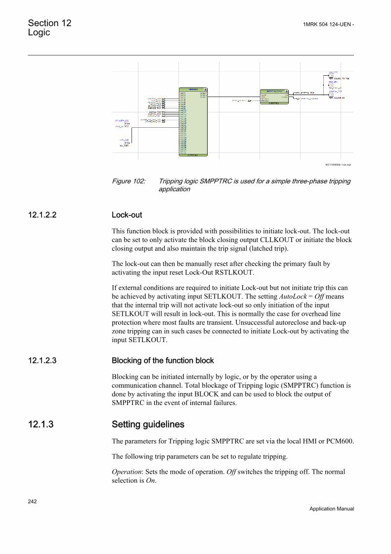
IEC11000054-1-en.vsd
IEC11000054 V1 EN
Figure 102: Tripping logic SMPPTRC is used for a simple three-phase trippingapplication
12.1.2.2 Lock-out
This function block is provided with possibilities to initiate lock-out. The lock-outcan be set to only activate the block closing output CLLKOUT or initiate the blockclosing output and also maintain the trip signal (latched trip).
The lock-out can then be manually reset after checking the primary fault byactivating the input reset Lock-Out RSTLKOUT.
If external conditions are required to initiate Lock-out but not initiate trip this canbe achieved by activating input SETLKOUT. The setting AutoLock = Off meansthat the internal trip will not activate lock-out so only initiation of the inputSETLKOUT will result in lock-out. This is normally the case for overhead lineprotection where most faults are transient. Unsuccessful autoreclose and back-upzone tripping can in such cases be connected to initiate Lock-out by activating theinput SETLKOUT.
12.1.2.3 Blocking of the function block
Blocking can be initiated internally by logic, or by the operator using acommunication channel. Total blockage of Tripping logic (SMPPTRC) function isdone by activating the input BLOCK and can be used to block the output ofSMPPTRC in the event of internal failures.
12.1.3 Setting guidelinesThe parameters for Tripping logic SMPPTRC are set via the local HMI or PCM600.
The following trip parameters can be set to regulate tripping.
Operation: Sets the mode of operation. Off switches the tripping off. The normalselection is On.
Section 12 1MRK 504 124-UEN -Logic
242Application Manual

TripLockout: Sets the scheme for lock-out. Off only activates lock-out output. Onactivates the lock-out output and latching output contacts. The normal selection isOff.
AutoLock: Sets the scheme for lock-out. Off only activates lock-out through theinput SETLKOUT. On also allows activation from trip function itself and activatesthe lockout output. The normal selection is Off.
tTripMin: Sets the required minimum duration of the trip pulse. It should be set toensure that the breaker is tripped and if a signal is used to start Breaker failureprotection CCRBRF longer than the back-up trip timer in CCRBRF. Normalsetting is 0.150s.
12.2 Trip matrix logic TMAGGIO
12.2.1 IdentificationFunction description IEC 61850
identificationIEC 60617identification
ANSI/IEEE C37.2device number
Trip matrix logic TMAGGIO - -
12.2.2 ApplicationTrip matrix logic TMAGGIO function is used to route trip signals and other logicaloutput signals to different output contacts on the IED.
TMAGGIO output signals and the physical outputs allows the user to adapt thesignals to the physical tripping outputs according to the specific application needs.
12.2.3 Setting guidelinesOperation: Operation of function On/Off.
PulseTime: Defines the pulse time delay. When used for direct tripping of circuitbreaker(s) the pulse time delay shall be set to approximately 0.150 seconds in orderto obtain satisfactory minimum duration of the trip pulse to the circuit breaker tripcoils.
OnDelay: Used to prevent output signals to be given for spurious inputs. Normallyset to 0 or a low value.
OffDelay: Defines a minimum on time for the outputs. When used for directtripping of circuit breaker(s) the off delay time shall be set to approximately 0.150seconds in order to obtain satisfactory minimum duration of the trip pulse to thecircuit breaker trip coils.
1MRK 504 124-UEN - Section 12Logic
243Application Manual

ModeOutputx: Defines if output signal OUTPUTx (where x=1-3) is Steady orPulsed.
12.3 Configurable logic blocks
12.3.1 IdentificationFunction description IEC 61850
identificationIEC 60617identification
ANSI/IEEE C37.2device number
OR Function block OR - -
Function description IEC 61850identification
IEC 60617identification
ANSI/IEEE C37.2device number
Inverter function block INVERTER - -
Function description IEC 61850identification
IEC 60617identification
ANSI/IEEE C37.2device number
PULSETIMER function block PULSETIMER - -
Function description IEC 61850identification
IEC 60617identification
ANSI/IEEE C37.2device number
Controllable gate function block GATE - -
Function description IEC 61850identification
IEC 60617identification
ANSI/IEEE C37.2device number
Exclusive OR function block XOR - -
Function description IEC 61850identification
IEC 60617identification
ANSI/IEEE C37.2device number
Logic loop delay function block LOOPDELAY - -
Function description IEC 61850identification
IEC 60617identification
ANSI/IEEE C37.2device number
Timer function block TIMERSET - -
Function description IEC 61850identification
IEC 60617identification
ANSI/IEEE C37.2device number
AND function block AND - -
Section 12 1MRK 504 124-UEN -Logic
244Application Manual

Function description IEC 61850identification
IEC 60617identification
ANSI/IEEE C37.2device number
Set-reset memory function block SRMEMORY - -
Function description IEC 61850identification
IEC 60617identification
ANSI/IEEE C37.2device number
Reset-set with memory function block RSMEMORY - -
12.3.2 ApplicationA set of standard logic blocks, like AND, OR etc, and timers are available foradapting the IED configuration to the specific application needs.
There are no settings for AND gates, OR gates, inverters or XOR gates.
For normal On/Off delay and pulse timers the time delays and pulse lengths are setfrom the local HMI or via the PST tool.
Both timers in the same logic block (the one delayed on pick-up and the onedelayed on drop-out) always have a common setting value.
For controllable gates, settable timers and SR flip-flops with memory, the settingparameters are accessible via the local HMI or via the PST tool.
12.3.3.1 Configuration
Logic is configured using the ACT configuration tool.
Execution of functions as defined by the configurable logic blocks runs accordingto a fixed sequence with different cycle times.
For each cycle time, the function block is given an serial execution number. This isshown when using the ACT configuration tool with the designation of the functionblock and the cycle time, see example below.
IEC09000695_2_en.vsdIEC09000695 V2 EN
Figure 103: Example designation, serial execution number and cycle time forlogic function
1MRK 504 124-UEN - Section 12Logic
245Application Manual

The execution of different function blocks within the same cycle is determined bythe order of their serial execution numbers. Always remember this whenconnecting two or more logical function blocks in series.
Always be careful when connecting function blocks with a fastcycle time to function blocks with a slow cycle time.Remember to design the logic circuits carefully and always checkthe execution sequence for different functions. In other cases,additional time delays must be introduced into the logic schemes toprevent errors, for example, race between functions.Default value on all four inputs of the AND gate are logical 1which makes it possible for the user to just use the required numberof inputs and leave the rest un-connected. The output OUT has adefault value 0 initially, which will suppress one cycle pulse if thefunction has been put in the wrong execution order.
12.4 Fixed signals FXDSIGN
12.4.1 IdentificationFunction description IEC 61850
identificationIEC 60617identification
ANSI/IEEE C37.2device number
Fixed signals FXDSIGN - -
12.4.2 ApplicationThe Fixed signals function (FXDSIGN) generates a number of pre-set (fixed)signals that can be used in the configuration of an IED, either for forcing theunused inputs in other function blocks to a certain level/value, or for creatingcertain logic.
Example for use of GRP_OFF signal in FXDSIGNThe Restricted earth fault function REFPDIF can be used both for auto-transformers and normal transformers.
When used for auto-transformers, information from both windings parts, togetherwith the neutral point current, needs to be available to the function. This means thatthree inputs are needed.
Section 12 1MRK 504 124-UEN -Logic
246Application Manual
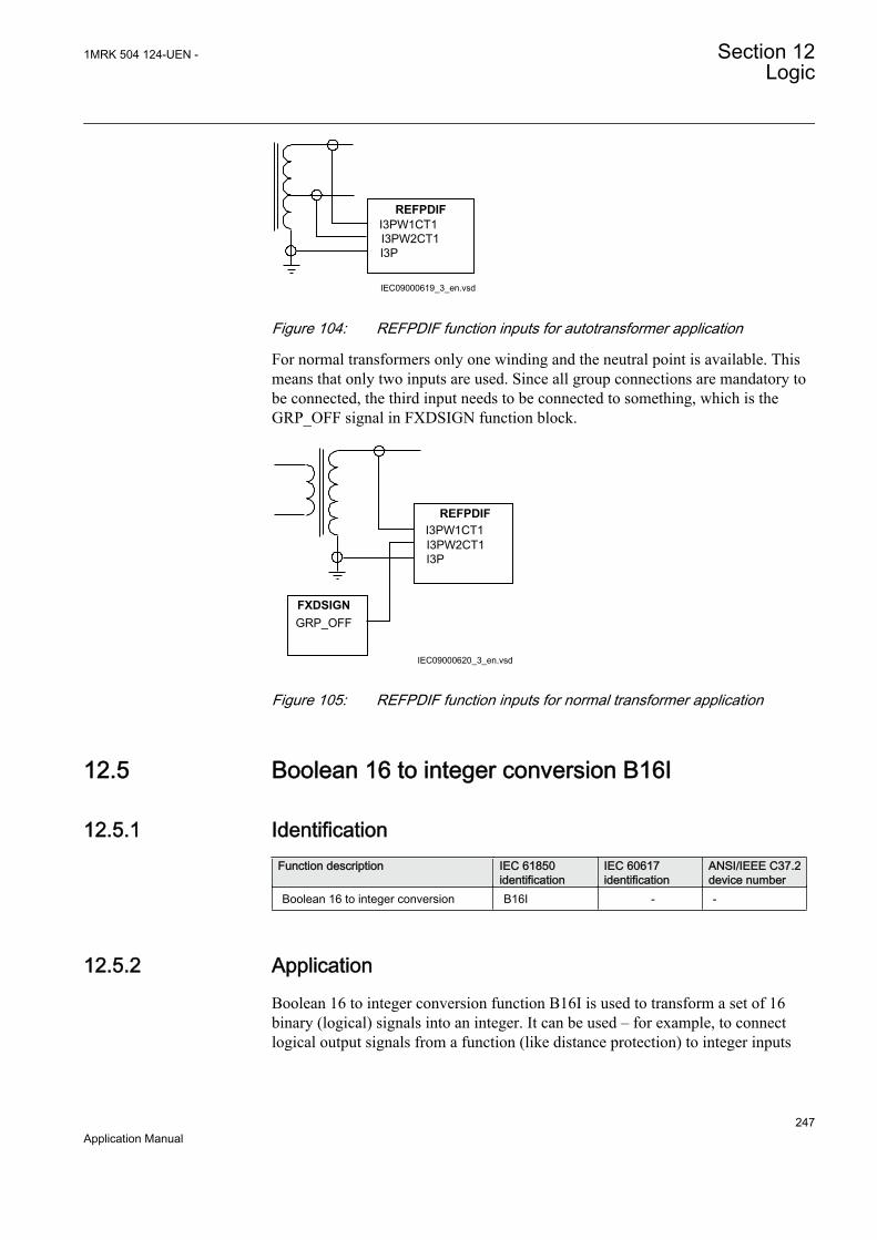
I3PW1CT1I3PW2CT1 I3P
REFPDIF
IEC09000619_3_en.vsdIEC09000619 V3 EN
Figure 104: REFPDIF function inputs for autotransformer application
For normal transformers only one winding and the neutral point is available. Thismeans that only two inputs are used. Since all group connections are mandatory tobe connected, the third input needs to be connected to something, which is theGRP_OFF signal in FXDSIGN function block.
I3PW1CT1I3PW2CT1 I3P
REFPDIF
GRP_OFFFXDSIGN
IEC09000620_3_en.vsdIEC09000620 V3 EN
Figure 105: REFPDIF function inputs for normal transformer application
12.5 Boolean 16 to integer conversion B16I
12.5.1 IdentificationFunction description IEC 61850
identificationIEC 60617identification
ANSI/IEEE C37.2device number
Boolean 16 to integer conversion B16I - -
12.5.2 ApplicationBoolean 16 to integer conversion function B16I is used to transform a set of 16binary (logical) signals into an integer. It can be used – for example, to connectlogical output signals from a function (like distance protection) to integer inputs
1MRK 504 124-UEN - Section 12Logic
247Application Manual

from another function (like line differential protection). B16I does not have alogical node mapping.
12.5.3 Setting guidelinesThe function does not have any parameters available in Local HMI or Protectionand Control IED Manager (PCM600).
12.6 Boolean 16 to integer conversion with logic noderepresentation B16IFCVI
12.6.1 IdentificationFunction description IEC 61850
identificationIEC 60617identification
ANSI/IEEE C37.2device number
Boolean 16 to integer conversion withlogic node representation
B16IFCVI - -
12.6.2 ApplicationBoolean 16 to integer conversion with logic node representation functionB16IFCVI is used to transform a set of 16 binary (logical) signals into an integer.B16IFCVI can receive an integer from a station computer – for example, over IEC61850. These functions are very useful when you want to generate logicalcommands (for selector switches or voltage controllers) by inputting an integernumber. B16IFCVI has a logical node mapping in IEC 61850.
12.6.3 Setting guidelinesThe function does not have any parameters available in the local HMI or Protectionand Control IED Manager (PCM600).
12.7 Integer to boolean 16 conversion IB16A
12.7.1 IdentificationFunction description IEC 61850
identificationIEC 60617identification
ANSI/IEEE C37.2device number
Integer to boolean 16 conversion IB16A - -
Section 12 1MRK 504 124-UEN -Logic
248Application Manual
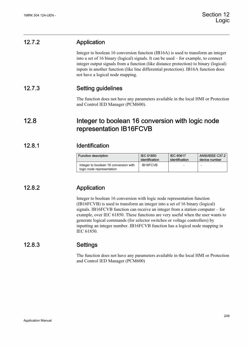
12.7.2 ApplicationInteger to boolean 16 conversion function (IB16A) is used to transform an integerinto a set of 16 binary (logical) signals. It can be used – for example, to connectinteger output signals from a function (like distance protection) to binary (logical)inputs in another function (like line differential protection). IB16A function doesnot have a logical node mapping.
12.7.3 Setting guidelinesThe function does not have any parameters available in the local HMI or Protectionand Control IED Manager (PCM600).
12.8 Integer to boolean 16 conversion with logic noderepresentation IB16FCVB
12.8.1 IdentificationFunction description IEC 61850
identificationIEC 60617identification
ANSI/IEEE C37.2device number
Integer to boolean 16 conversion withlogic node representation
IB16FCVB - -
12.8.2 ApplicationInteger to boolean 16 conversion with logic node representation function(IB16FCVB) is used to transform an integer into a set of 16 binary (logical)signals. IB16FCVB function can receive an integer from a station computer – forexample, over IEC 61850. These functions are very useful when the user wants togenerate logical commands (for selector switches or voltage controllers) byinputting an integer number. IB16FCVB function has a logical node mapping inIEC 61850.
12.8.3 SettingsThe function does not have any parameters available in the local HMI or Protectionand Control IED Manager (PCM600)
1MRK 504 124-UEN - Section 12Logic
249Application Manual

250

Section 13 Monitoring
13.1 IEC61850 generic communication I/O functionsSPGGIO
13.1.1 IdentificationFunction description IEC 61850
identificationIEC 60617identification
ANSI/IEEE C37.2device number
IEC 61850 generic communication I/Ofunctions
SPGGIO - -
13.1.2 ApplicationIEC 61850 generic communication I/O functions (SPGGIO) function is used tosend one single logical output to other systems or equipment in the substation. Ithas one visible input, that should be connected in ACT tool.
13.1.3 Setting guidelinesThe function does not have any parameters available in Local HMI or Protectionand Control IED Manager (PCM600).
13.2 IEC61850 generic communication I/O functions 16inputs SP16GGIO
13.2.1 IdentificationFunction description IEC 61850
identificationIEC 60617identification
ANSI/IEEE C37.2device number
IEC 61850 generic communication I/Ofunctions 16 inputs
SP16GGIO - -
13.2.2 ApplicationSP16GGIO function block is used to send up to 16 logical signals to other systemsor equipment in the substation. Inputs should be connected in ACT tool.
1MRK 504 124-UEN - Section 13Monitoring
251Application Manual

13.2.3 Setting guidelinesThe function does not have any parameters available in Local HMI or Protectionand Control IED Manager (PCM600).
13.3 IEC61850 generic communication I/O functionsMVGGIO
13.3.1 IdentificationFunction description IEC 61850
identificationIEC 60617identification
ANSI/IEEE C37.2device number
IEC61850 generic communication I/Ofunctions
MVGGIO - -
13.3.2 ApplicationIEC61850 generic communication I/O functions (MVGGIO) function is used tosend the instantaneous value of an analog output to other systems or equipment inthe substation. It can also be used inside the same IED, to attach a RANGE aspectto an analog value and to permit measurement supervision on that value.
13.3.3 Setting guidelinesThe settings available for IEC61850 generic communication I/O functions(MVGGIO) function allows the user to choose a deadband and a zero deadband forthe monitored signal. Values within the zero deadband are considered as zero.
The high and low limit settings provides limits for the high-high-, high, normal,low and low-low ranges of the measured value. The actual range of the measuredvalue is shown on the range output of MVGGIO function block. When a Measuredvalue expander block (MVEXP) is connected to the range output, the logicaloutputs of the MVEXP are changed accordingly.
Section 13 1MRK 504 124-UEN -Monitoring
252Application Manual
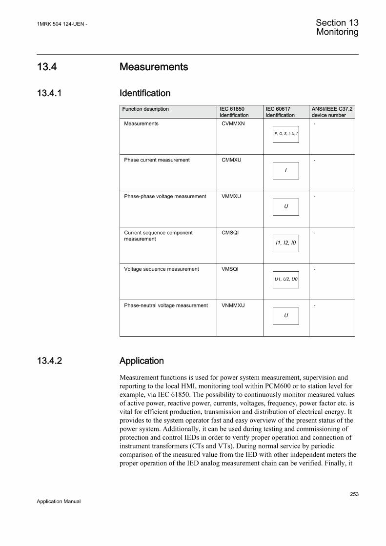
13.4 Measurements
13.4.1 IdentificationFunction description IEC 61850
identificationIEC 60617identification
ANSI/IEEE C37.2device number
Measurements CVMMXN
P, Q, S, I, U, f
SYMBOL-RR V1 EN
-
Phase current measurement CMMXU
I
SYMBOL-SS V1 EN
-
Phase-phase voltage measurement VMMXU
U
SYMBOL-UU V1 EN
-
Current sequence componentmeasurement
CMSQI
I1, I2, I0
SYMBOL-VV V1 EN
-
Voltage sequence measurement VMSQI
U1, U2, U0
SYMBOL-TT V1 EN
-
Phase-neutral voltage measurement VNMMXU
U
SYMBOL-UU V1 EN
-
13.4.2 ApplicationMeasurement functions is used for power system measurement, supervision andreporting to the local HMI, monitoring tool within PCM600 or to station level forexample, via IEC 61850. The possibility to continuously monitor measured valuesof active power, reactive power, currents, voltages, frequency, power factor etc. isvital for efficient production, transmission and distribution of electrical energy. Itprovides to the system operator fast and easy overview of the present status of thepower system. Additionally, it can be used during testing and commissioning ofprotection and control IEDs in order to verify proper operation and connection ofinstrument transformers (CTs and VTs). During normal service by periodiccomparison of the measured value from the IED with other independent meters theproper operation of the IED analog measurement chain can be verified. Finally, it
1MRK 504 124-UEN - Section 13Monitoring
253Application Manual
can be used to verify proper direction orientation for distance or directionalovercurrent protection function.
The available measured values of an IED are depending on theactual hardware (TRM) and the logic configuration made in PCM600.
All measured values can be supervised with four settable limits that is, low-lowlimit, low limit, high limit and high-high limit. A zero clamping reduction is alsosupported, that is, the measured value below a settable limit is forced to zero whichreduces the impact of noise in the inputs. There are no interconnections regardingany settings or parameters, neither between functions nor between signals withineach function.
Zero clampings are handled by ZeroDb for each signal separately for each of thefunctions. For example, the zero clamping of U12 is handled by ULZeroDb inVMMXU, zero clamping of I1 is handled by ILZeroDb in CMMXU.
Dead-band supervision can be used to report measured signal value to station levelwhen change in measured value is above set threshold limit or time integral of allchanges since the last time value updating exceeds the threshold limit. Measurevalue can also be based on periodic reporting.
The measurement function, CVMMXN, provides the following power systemquantities:
• P, Q and S: three phase active, reactive and apparent power• PF: power factor• U: phase-to-phase voltage amplitude• I: phase current amplitude• F: power system frequency
The output values are displayed in the local HMI under Main menu/Tests/Function status/Monitoring/CVMMXN/Outputs
The measuring functions CMMXU, VNMMXU and VMMXU provide physicalquantities:
• I: phase currents (amplitude and angle) (CMMXU)• U: voltages (phase-to-earth and phase-to-phase voltage, amplitude and angle)
(VMMXU, VNMMXU)
It is possible to calibrate the measuring function above to get better then class 0.5presentation. This is accomplished by angle and amplitude compensation at 5, 30and 100% of rated current and at 100% of rated voltage.
The power system quantities provided, depends on the actualhardware, (TRM) and the logic configuration made in PCM600.
Section 13 1MRK 504 124-UEN -Monitoring
254Application Manual

The measuring functions CMSQI and VMSQI provide sequential quantities:
• I: sequence currents (positive, zero, negative sequence, amplitude and angle)• U: sequence voltages (positive, zero and negative sequence, amplitude and
angle).
The CVMMXN function calculates three-phase power quantities by usingfundamental frequency phasors (DFT values) of the measured current respectivelyvoltage signals. The measured power quantities are available either, asinstantaneously calculated quantities or, averaged values over a period of time (lowpass filtered) depending on the selected settings.
13.4.3 Setting guidelinesThe available setting parameters of the measurement function CVMMXN,CMMXU, VMMXU, CMSQI, VMSQI, VNMMXU are depending on the actualhardware (TRM) and the logic configuration made in PCM600.
The parameters for the Measurement functions CVMMXN, CMMXU, VMMXU,CMSQI, VMSQI, VNMMXU are set via the local HMI or PCM600.
Common base IED values for primary current (IBase), primary voltage (UBase)and primary power (SBase) are set in a Global base values for settings functionGBASVAL. Setting GlobalBaseSel is used to select a GBASVAL function forreference of base values.
Operation: Off/On. Every function instance (CVMMXN, CMMXU, VMMXU,CMSQI, VMSQI, VNMMXU) can be taken in operation (On) or out of operation(Off).
The following general settings can be set for the Measurement function(CVMMXN).
PowAmpFact: Amplitude factor to scale power calculations.
PowAngComp: Angle compensation for phase shift between measured I & U.
Mode: Selection of measured current and voltage. There are 9 different ways ofcalculating monitored three-phase values depending on the available VT inputsconnected to the IED. See parameter group setting table.
k: Low pass filter coefficient for power measurement, U and I.
UAmpCompY: Amplitude compensation to calibrate voltage measurements at Y%of Ur, where Y is equal to 5, 30 or 100.
IAmpCompY: Amplitude compensation to calibrate current measurements at Y% ofIr, where Y is equal to 5, 30 or 100.
IAngCompY: Angle compensation to calibrate angle measurements at Y% of Ir,where Y is equal to 5, 30 or 100.
1MRK 504 124-UEN - Section 13Monitoring
255Application Manual
The following general settings can be set for the Phase-phase currentmeasurement (CMMXU).
IAmpCompY: Amplitude compensation to calibrate current measurements at Y% ofIr, where Y is equal to 5, 30 or 100.
IAngCompY: Angle compensation to calibrate angle measurements at Y% of Ir,where Y is equal to 5, 30 or 100.
The following general settings can be set for the Phase-phase voltagemeasurement (VMMXU).
UAmpCompY: Amplitude compensation to calibrate voltage measurements at Y%of Ur, where Y is equal to 5, 30 or 100.
UAngCompY: Angle compensation to calibrate angle measurements at Y% of Ur,where Y is equal to 5, 30 or 100.
The following general settings can be set for all monitored quantities included inthe functions (CVMMXN, CMMXU, VMMXU, CMSQI, VMSQI, VNMMXU) Xin setting names below equals S, P, Q, PF, U, I, F, IL1-3, UL1-3UL12-31, I1, I2,3I0, U1, U2 or 3U0.
Xmin: Minimum value for analog signal X.
Xmax: Maximum value for analog signal X.
Xmin and Xmax values are directly set in applicable measuring unit,V, A, and so on, for all measurement functions, except CVMMXNwhere Xmin and Xmax values are set in % of SBase.
XZeroDb: Zero point clamping. A signal value less than XZeroDb is forced to zero.
XRepTyp: Reporting type. Cyclic (Cyclic), amplitude deadband (Dead band) orintegral deadband (Int deadband). The reporting interval is controlled by theparameter XDbRepInt.
XDbRepInt: Reporting deadband setting. Cyclic reporting is the setting value and isreporting interval in seconds. Amplitude deadband is the setting value in % ofmeasuring range. Integral deadband setting is the integral area, that is, measuredvalue in % of measuring range multiplied by the time between two measured values.
Limits are directly set in applicable measuring unit, V, A , and soon, for all measurement functions, except CVMMXN where limitsare set in % of SBase.
XHiHiLim: High-high limit.
XHiLim: High limit.
Section 13 1MRK 504 124-UEN -Monitoring
256Application Manual
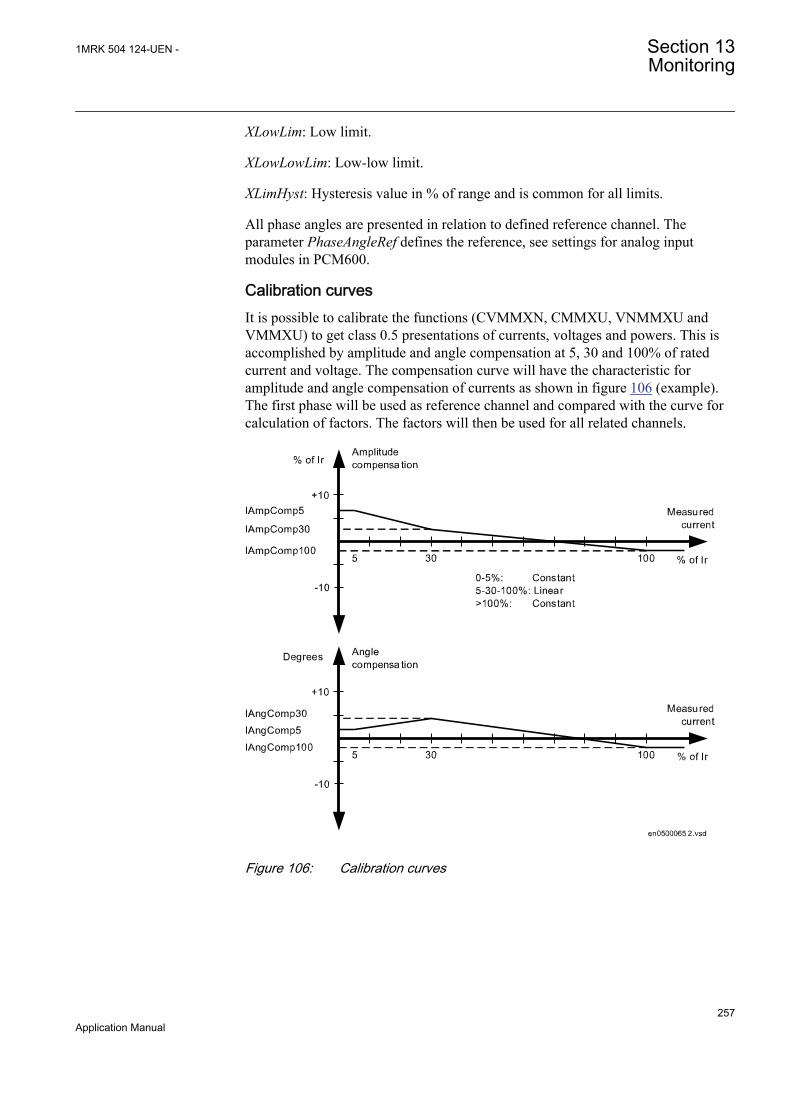
XLowLim: Low limit.
XLowLowLim: Low-low limit.
XLimHyst: Hysteresis value in % of range and is common for all limits.
All phase angles are presented in relation to defined reference channel. Theparameter PhaseAngleRef defines the reference, see settings for analog inputmodules in PCM600.
Calibration curvesIt is possible to calibrate the functions (CVMMXN, CMMXU, VNMMXU andVMMXU) to get class 0.5 presentations of currents, voltages and powers. This isaccomplished by amplitude and angle compensation at 5, 30 and 100% of ratedcurrent and voltage. The compensation curve will have the characteristic foramplitude and angle compensation of currents as shown in figure 106 (example).The first phase will be used as reference channel and compared with the curve forcalculation of factors. The factors will then be used for all related channels.
IEC05000652 V2 EN
Figure 106: Calibration curves
1MRK 504 124-UEN - Section 13Monitoring
257Application Manual

13.4.4 Setting examplesThree setting examples, in connection to Measurement function (CVMMXN), areprovided:
• Measurement function (CVMMXN) application for a 400 kV OHL• Measurement function (CVMMXN) application on the secondary side of a
transformer• Measurement function (CVMMXN) application for a generator
For each of them detail explanation and final list of selected setting parametersvalues will be provided.
The available measured values of an IED are depending on theactual hardware (TRM) and the logic configuration made in PCM600.
13.4.4.1 Measurement function application for a 400 kV OHL
Single line diagram for this application is given in figure 107:
400kV Busbar
400kV OHL
P Q
800/1 A400 0,1/
3 3kV
IEC09000039-1-en.vsd
IED
IEC09000039-1-EN V1 EN
Figure 107: Single line diagram for 400 kV OHL application
In order to monitor, supervise and calibrate the active and reactive power asindicated in figure 107 it is necessary to do the following:
Section 13 1MRK 504 124-UEN -Monitoring
258Application Manual
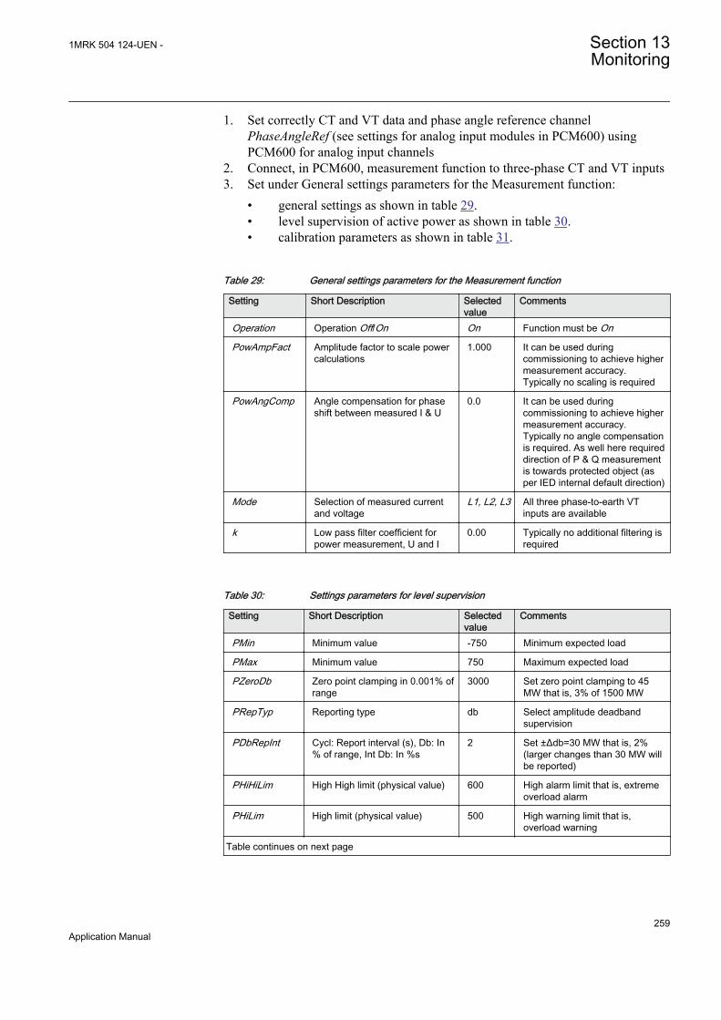
1. Set correctly CT and VT data and phase angle reference channelPhaseAngleRef (see settings for analog input modules in PCM600) usingPCM600 for analog input channels
2. Connect, in PCM600, measurement function to three-phase CT and VT inputs3. Set under General settings parameters for the Measurement function:
• general settings as shown in table 29.• level supervision of active power as shown in table 30.• calibration parameters as shown in table 31.
Table 29: General settings parameters for the Measurement function
Setting Short Description Selectedvalue
Comments
Operation Operation Off/On On Function must be On
PowAmpFact Amplitude factor to scale powercalculations
1.000 It can be used duringcommissioning to achieve highermeasurement accuracy.Typically no scaling is required
PowAngComp Angle compensation for phaseshift between measured I & U
0.0 It can be used duringcommissioning to achieve highermeasurement accuracy.Typically no angle compensationis required. As well here requireddirection of P & Q measurementis towards protected object (asper IED internal default direction)
Mode Selection of measured currentand voltage
L1, L2, L3 All three phase-to-earth VTinputs are available
k Low pass filter coefficient forpower measurement, U and I
0.00 Typically no additional filtering isrequired
Table 30: Settings parameters for level supervision
Setting Short Description Selectedvalue
Comments
PMin Minimum value -750 Minimum expected load
PMax Minimum value 750 Maximum expected load
PZeroDb Zero point clamping in 0.001% ofrange
3000 Set zero point clamping to 45MW that is, 3% of 1500 MW
PRepTyp Reporting type db Select amplitude deadbandsupervision
PDbRepInt Cycl: Report interval (s), Db: In% of range, Int Db: In %s
2 Set ±Δdb=30 MW that is, 2%(larger changes than 30 MW willbe reported)
PHiHiLim High High limit (physical value) 600 High alarm limit that is, extremeoverload alarm
PHiLim High limit (physical value) 500 High warning limit that is,overload warning
Table continues on next page
1MRK 504 124-UEN - Section 13Monitoring
259Application Manual

Setting Short Description Selectedvalue
Comments
PLowLim Low limit (physical value) -800 Low warning limit. Not active
PLowLowlLim Low Low limit (physical value) -800 Low alarm limit. Not active
PLimHyst Hysteresis value in % of range(common for all limits)
2 Set ±Δ Hysteresis MW that is, 2%
Table 31: Settings for calibration parameters
Setting Short Description Selectedvalue
Comments
IAmpComp5 Amplitude factor to calibratecurrent at 5% of Ir
0.00
IAmpComp30 Amplitude factor to calibratecurrent at 30% of Ir
0.00
IAmpComp100 Amplitude factor to calibratecurrent at 100% of Ir
0.00
UAmpComp5 Amplitude factor to calibratevoltage at 5% of Ur
0.00
UAmpComp30 Amplitude factor to calibratevoltage at 30% of Ur
0.00
UAmpComp100 Amplitude factor to calibratevoltage at 100% of Ur
0.00
IAngComp5 Angle calibration for current at5% of Ir
0.00
IAngComp30 Angle pre-calibration for currentat 30% of Ir
0.00
IAngComp100 Angle pre-calibration for currentat 100% of Ir
0.00
13.4.4.2 Measurement function application for a power transformer
Single line diagram for this application is given in figure 108.
Section 13 1MRK 504 124-UEN -Monitoring
260Application Manual
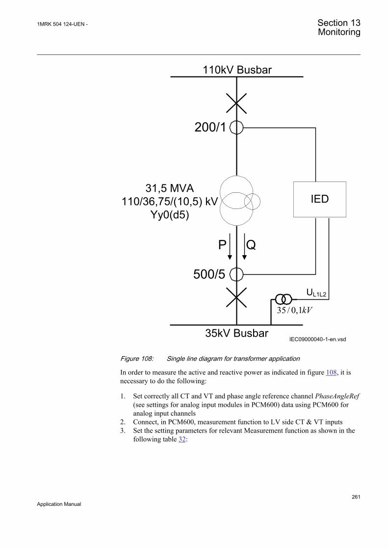
110kV Busbar
200/1
35 / 0,1kV
35kV Busbar
500/5
P Q
31,5 MVA110/36,75/(10,5) kV
Yy0(d5)
UL1L2
IEC09000040-1-en.vsd
IED
IEC09000040-1-EN V1 EN
Figure 108: Single line diagram for transformer application
In order to measure the active and reactive power as indicated in figure 108, it isnecessary to do the following:
1. Set correctly all CT and VT and phase angle reference channel PhaseAngleRef(see settings for analog input modules in PCM600) data using PCM600 foranalog input channels
2. Connect, in PCM600, measurement function to LV side CT & VT inputs3. Set the setting parameters for relevant Measurement function as shown in the
following table 32:
1MRK 504 124-UEN - Section 13Monitoring
261Application Manual

Table 32: General settings parameters for the Measurement function
Setting Short description Selectedvalue
Comment
Operation Operation Off/On On Function must be On
PowAmpFact Amplitude factor to scale powercalculations
1.000 Typically no scaling is required
PowAngComp Angle compensation for phaseshift between measured I & U
180.0 Typically no angle compensationis required. However here therequired direction of P & Qmeasurement is towards busbar(Not per IED internal defaultdirection). Therefore anglecompensation have to be used inorder to get measurements inaliment with the requireddirection.
Mode Selection of measured currentand voltage
L1L2 Only UL1L2 phase-to-phasevoltage is available
k Low pass filter coefficient forpower measurement, U and I
0.00 Typically no additional filtering isrequired
13.5 Event counter CNTGGIO
13.5.1 IdentificationFunction description IEC 61850
identificationIEC 60617identification
ANSI/IEEE C37.2device number
Event counter CNTGGIOS00946 V1 EN
-
13.5.2 ApplicationEvent counter (CNTGGIO) has six counters which are used for storing the numberof times each counter has been activated. CNTGGIO can be used to count howmany times a specific function, for example the tripping logic, has issued a tripsignal. All six counters have a common blocking and resetting feature.
13.5.3 Setting guidelinesOperation: Sets the operation of Event counter (CNTGGIO) On or Off.
Section 13 1MRK 504 124-UEN -Monitoring
262Application Manual

13.6 Disturbance report
13.6.1 IdentificationFunction description IEC 61850
identificationIEC 60617identification
ANSI/IEEE C37.2device number
Disturbance report DRPRDRE - -
Analog input signals A1RADR - -
Analog input signals A2RADR - -
Analog input signals A3RADR - -
Analog input signals A4RADR - -
Binary input signals B1RBDR - -
Binary input signals B2RBDR - -
Binary input signals B3RBDR - -
Binary input signals B4RBDR - -
Binary input signals B5RBDR - -
Binary input signals B6RBDR - -
13.6.2 ApplicationTo get fast, complete and reliable information about disturbances in the primary and/or in the secondary system it is very important to gather information on faultcurrents, voltages and events. It is also important having a continuous event-logging to be able to monitor in an overview perspective. These tasks areaccomplished by the disturbance report function DRPRDRE and facilitate a betterunderstanding of the power system behavior and related primary and secondaryequipment during and after a disturbance. An analysis of the recorded dataprovides valuable information that can be used to explain a disturbance, basis forchange of IED setting plan, improve existing equipment, and so on. Thisinformation can also be used in a longer perspective when planning for anddesigning new installations, that is, a disturbance recording could be a part ofFunctional Analysis (FA).
Disturbance report DRPRDRE, always included in the IED, acquires sampled dataof all selected analog and binary signals connected to the function blocks that is,
• maximum 30 external analog signals,• 10 internal derived analog signals, and• 96 binary signals.
Disturbance report function is a common name for several functions that is,Indications, Event recorder, Event list, Trip value recorder, Disturbance recorder.
Disturbance report function is characterized by great flexibility as far asconfiguration, starting conditions, recording times, and large storage capacity are
1MRK 504 124-UEN - Section 13Monitoring
263Application Manual

concerned. Thus, disturbance report is not dependent on the operation of protectivefunctions, and it can record disturbances that were not discovered by protectivefunctions for one reason or another. Disturbance report can be used as an advancedstand-alone disturbance recorder.
Every disturbance report recording is saved in the IED. The same applies to allevents, which are continuously saved in a ring-buffer. Local HMI can be used toget information about the recordings, and the disturbance report files may beuploaded in the PCM600 using the Disturbance handling tool, for report reading orfurther analysis (using WaveWin, that can be found on the PCM600 installationCD). The user can also upload disturbance report files using FTP or MMS (over61850) clients.
If the IED is connected to a station bus (IEC 61850-8-1), the disturbance recorder(record made and fault number) and the fault locator information are available asGOOSE or Report Control data.
13.6.3 Setting guidelinesThe setting parameters for the Disturbance report function DRPRDRE are set viathe local HMI or PCM600.
It is possible to handle up to 40 analog and 96 binary signals, either internal signalsor signals coming from external inputs. The binary signals are identical in allfunctions that is, Disturbance recorder, Event recorder, Indication, Trip valuerecorder and Event list function.
User-defined names of binary and analog input signals is set using PCM600. Theanalog and binary signals appear with their user-defined names. The name is usedin all related functions (Disturbance recorder, Event recorder, Indication, Tripvalue recorder and Event list).
Figure 109 shows the relations between Disturbance report, included functions andfunction blocks. Event list, Event recorder and Indication uses information fromthe binary input function blocks (BxRBDR). Trip value recorder uses analoginformation from the analog input function blocks (AxRADR),. Disturbance reportfunction acquires information from both AxRADR and BxRBDR.
Section 13 1MRK 504 124-UEN -Monitoring
264Application Manual
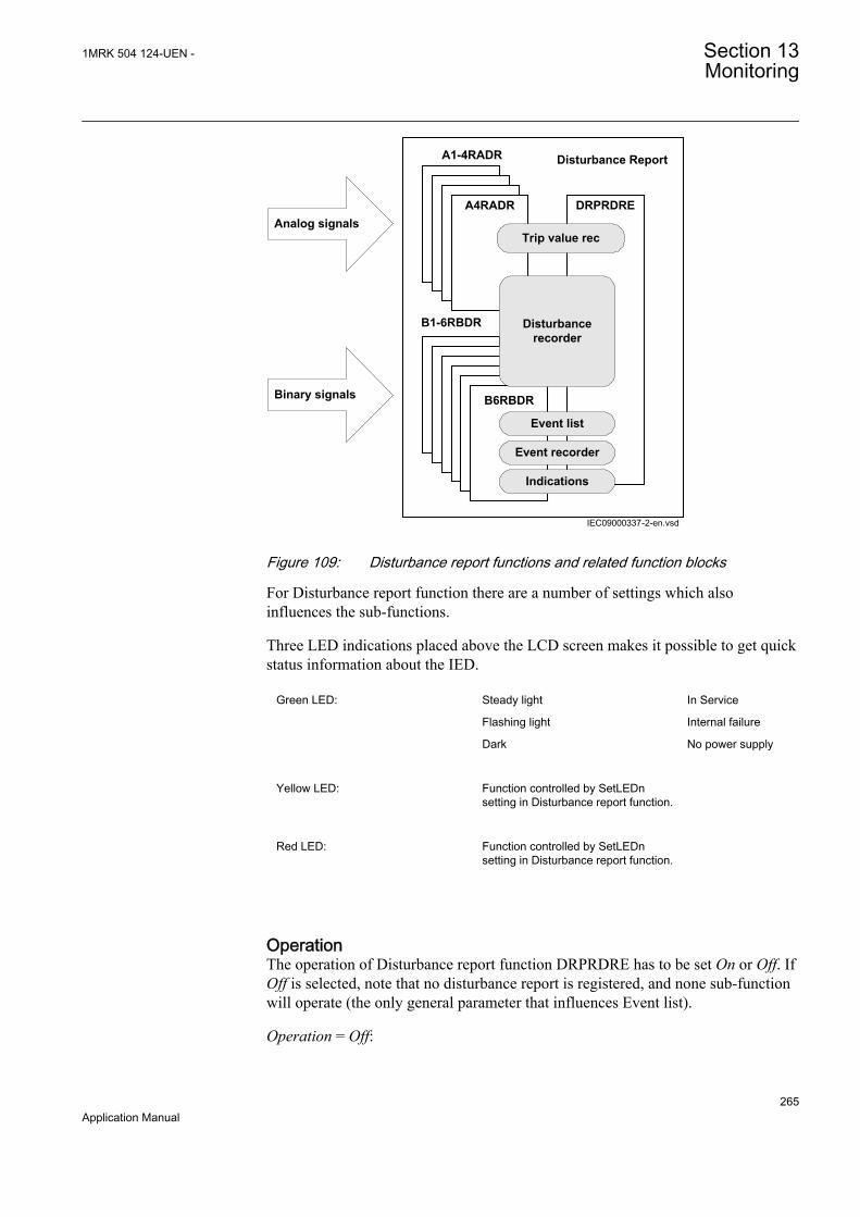
Trip value rec
Event list
Event recorder
Indications
Disturbancerecorder
A1-4RADR
B1-6RBDR
Disturbance Report
Binary signals
Analog signalsA4RADR
B6RBDR
DRPRDRE
IEC09000337-2-en.vsdIEC09000337 V2 EN
Figure 109: Disturbance report functions and related function blocks
For Disturbance report function there are a number of settings which alsoinfluences the sub-functions.
Three LED indications placed above the LCD screen makes it possible to get quickstatus information about the IED.
Green LED: Steady light In Service
Flashing light Internal failure
Dark No power supply
Yellow LED: Function controlled by SetLEDnsetting in Disturbance report function.
Red LED: Function controlled by SetLEDnsetting in Disturbance report function.
OperationThe operation of Disturbance report function DRPRDRE has to be set On or Off. IfOff is selected, note that no disturbance report is registered, and none sub-functionwill operate (the only general parameter that influences Event list).
Operation = Off:
1MRK 504 124-UEN - Section 13Monitoring
265Application Manual
• Disturbance reports are not stored.• LED information (yellow - start, red - trip) is not stored or changed.
Operation = On:
• Disturbance reports are stored, disturbance data can be read from the localHMI and from a PC using PCM600.
• LED information (yellow - start, red - trip) is stored.
Every recording will get a number (0 to 999) which is used as identifier (localHMI, disturbance handling tool and IEC 61850). An alternative recordingidentification is date, time and sequence number. The sequence number isautomatically increased by one for each new recording and is reset to zero atmidnight. The maximum number of recordings stored in the IED is 100. The oldestrecording will be overwritten when a new recording arrives (FIFO).
To be able to delete disturbance records, Operation parameter hasto be On.
The maximum number of recordings depend on each recordingstotal recording time. Long recording time will reduce the number ofrecordings to less than 100.
The IED flash disk should NOT be used to store any user files. Thismight cause disturbance recordings to be deleted due to lack of diskspace.
Recording timesThe different recording times for Disturbance report are set (the pre-fault time, post-fault time, and limit time). These recording times affect all sub-functions more orless but not the Event list function.
Prefault recording time (PreFaultRecT) is the recording time before the startingpoint of the disturbance. The setting should be at least 0.1 s to ensure enoughsamples for the estimation of pre-fault values in the Trip value recorder function.
Postfault recording time (PostFaultRecT) is the maximum recording time after thedisappearance of the trig-signal (does not influence the Trip value recorder function).
Recording time limit (TimeLimit) is the maximum recording time after trig. Theparameter limits the recording time if some trigging condition (fault-time) is verylong or permanently set (does not influence the Trip value recorder function).
Section 13 1MRK 504 124-UEN -Monitoring
266Application Manual

Post retrigger (PostRetrig) can be set to On or Off. Makes it possible to chooseperformance of Disturbance report function if a new trig signal appears in the post-fault window.
PostRetrig = Off
The function is insensitive for new trig signals during post fault time.
PostRetrig = On
The function completes current report and starts a new complete report that is, thelatter will include:
• new pre-fault- and fault-time (which will overlap previous report)• events and indications might be saved in the previous report too, due to overlap• new trip value calculations if installed, in operation and started
Operation in test modeIf the IED is in test mode and OpModeTest = Off. Disturbance report function doesnot save any recordings and no LED information is displayed.
If the IED is in test mode and OpModeTest = On. Disturbance report functionworks in normal mode and the status is indicated in the saved recording.
13.6.3.1 Binary input signals
Up to 96 binary signals can be selected among internal logical and binary inputsignals. The configuration tool is used to configure the signals.
For each of the 96 signals, it is also possible to select if the signal is to be used as atrigger for the start of Disturbance report and if the trigger should be activated onpositive (1) or negative (0) slope.
OperationN: Disturbance report may trig for binary input N (On) or not (Off).
TrigLevelN: Trig on positive (Trig on 1) or negative (Trig on 0) slope for binaryinput N.
13.6.3.2 Analog input signals
Up to 40 analog signals can be selected among internal analog and analog inputsignals. PCM600 is used to configure the signals.
The analog trigger of Disturbance report is not affected if analog input M is to beincluded in the disturbance recording or not (OperationM = On/Off).
If OperationM = Off, no waveform (samples) will be recorded and reported ingraph. However, Trip value, pre-fault and fault value will be recorded and reported.The input channel can still be used to trig the disturbance recorder.
1MRK 504 124-UEN - Section 13Monitoring
267Application Manual
If OperationM = On, waveform (samples) will also be recorded and reported in graph.
NomValueM: Nominal value for input M.
OverTrigOpM, UnderTrigOpM: Over or Under trig operation, Disturbance reportmay trig for high/low level of analog input M (On) or not (Off).
OverTrigLeM, UnderTrigLeM: Over or under trig level, Trig high/low levelrelative nominal value for analog input M in percent of nominal value.
13.6.3.3 Sub-function parameters
All functions are in operation as long as Disturbance report is in operation.
IndicationsIndicationMaN: Indication mask for binary input N. If set (Show), a status changeof that particular input, will be fetched and shown in the disturbance summary onlocal HMI. If not set (Hide), status change will not be indicated.
SetLEDN: Set yellow Startand red Trip LED on local HMI in front of the IED ifbinary input N changes status.
Disturbance recorderOperationM: Analog channel M is to be recorded by the disturbance recorder (On)or not (Off).
If OperationM = Off, no waveform (samples) will be recorded and reported ingraph. However, Trip value, pre-fault and fault value will be recorded and reported.The input channel can still be used to trig the disturbance recorder.
If OperationM = On, waveform (samples) will also be recorded and reported in graph.
Event recorderEvent recorder function has no dedicated parameters.
Trip value recorderZeroAngleRef: The parameter defines which analog signal that will be used asphase angle reference for all other analog input signals. This signal will also beused for frequency measurement and the measured frequency is used whencalculating trip values. It is suggested to point out a sampled voltage input signal,for example, a line or busbar phase voltage (channel 1-30).
Event listEvent list function has no dedicated parameters.
13.6.3.4 Consideration
The density of recording equipment in power systems is increasing, since thenumber of modern IEDs, where recorders are included, is increasing. This leads toa vast number of recordings at every single disturbance and a lot of information has
Section 13 1MRK 504 124-UEN -Monitoring
268Application Manual

to be handled if the recording functions do not have proper settings. The goal is tooptimize the settings in each IED to be able to capture just valuable disturbancesand to maximize the number that is possible to save in the IED.
The recording time should not be longer than necessary (PostFaultrecT andTimeLimit).
• Should the function record faults only for the protected object or cover more?• How long is the longest expected fault clearing time?• Is it necessary to include reclosure in the recording or should a persistent fault
generate a second recording (PostRetrig)?
Minimize the number of recordings:
• Binary signals: Use only relevant signals to start the recording that is,protection trip, carrier receive and/or start signals.
• Analog signals: The level triggering should be used with great care, sinceunfortunate settings will cause enormously number of recordings. Ifnevertheless analog input triggering is used, chose settings by a sufficientmargin from normal operation values. Phase voltages are not recommended fortrigging.
Remember that values of parameters set elsewhere are linked to the information ona report. Such parameters are, for example, station and object identifiers, CT andVT ratios.
13.7 Measured value expander block MVEXP
13.7.1 IdentificationFunction description IEC 61850
identificationIEC 60617identification
ANSI/IEEE C37.2device number
Measured value expander block MVEXP - -
13.7.2 ApplicationThe current and voltage measurements functions (CVMMXN, CMMXU, VMMXUand VNMMXU), current and voltage sequence measurement functions (CMSQIand VMSQI) and IEC 61850 generic communication I/O functions (MVGGIO) areprovided with measurement supervision functionality. All measured values can besupervised with four settable limits, that is low-low limit, low limit, high limit andhigh-high limit. The measure value expander block (MVEXP) has been introducedto be able to translate the integer output signal from the measuring functions to 5binary signals, that is below low-low limit, below low limit, normal, above high-high limit or above high limit. The output signals can be used as conditions in theconfigurable logic.
1MRK 504 124-UEN - Section 13Monitoring
269Application Manual

13.7.3 Setting guidelinesThe function does not have any parameters available in Local HMI or Protectionand Control IED Manager (PCM600).
Common base IED values for primary current (IBase), primary voltage (UBase)and primary power (SBase) are set in a Global base values for settings functionGBASVAL. Setting GlobalBaseSel is used to select a GBASVAL function forreference of base values.
13.8 Station battery supervision SPVNZBAT
13.8.1 IdentificationFunction description IEC 61850
identificationIEC 60617identification
ANSI/IEEE C37.2device number
Station battery supervision function SPVNZBAT U<> -
13.8.2 ApplicationUsually, the load on the DC system is a constant resistance load, for example,lamps, LEDs, electronic instruments and electromagnetic contactors in a steadystate condition. A transient RL load exists when breakers are tripped or closed.
The battery voltage has to be continuously monitored as the batteries can withstandmoderate overvoltage and undervoltage only for a short period of time.
• If the battery is subjected to a prolonged or frequent overvoltage, it leads to theageing of the battery, which may lead to the earlier failure of the battery. Theother occurrences may be the thermal runaway, generation of heat or increasedamount of hydrogen gas and the depletion of fluid in case of valve regulatedbatteries.
• If the value of the charging voltage drops below the minimum recommendedfloat voltage of the battery, the battery does not receive sufficient chargingcurrent to offset internal losses, resulting in a gradual loss of capacity.• If a lead acid battery is subjected to a continuous undervoltage, heavy
sulfation occurs on the plates, which leads to the loss of the battery capacity.
Section 13 1MRK 504 124-UEN -Monitoring
270Application Manual

13.9 Insulation gas monitoring function SSIMG
13.9.1 IdentificationFunction description IEC 61850
identificationIEC 60617identification
ANSI/IEEE C37.2device number
Insulation gas monitoring function SSIMG - 63
13.9.2 ApplicationInsulation gas monitoring function (SSIMG) is used for monitoring the circuitbreaker condition. Proper arc extinction by the compressed gas in the circuitbreaker is very important. When the pressure becomes too low compared to therequired value, the circuit breaker operation gets blocked to avoid disaster. Binaryinformation based on the gas pressure in the circuit breaker is used as input signalsto the function. In addition to that, the function generates alarms based on receivedinformation.
13.10 Insulation liquid monitoring function SSIML
13.10.1 IdentificationFunction description IEC 61850
identificationIEC 60617identification
ANSI/IEEE C37.2device number
Insulation liquid monitoring function SSIML - 71
13.10.2 ApplicationInsulation liquid monitoring function (SSIML) is used for monitoring the circuitbreaker condition. Proper arc extinction by the compressed oil in the circuit breakeris very important. When the level becomes too low, compared to the requiredvalue, the circuit breaker operation is blocked to avoid disaster. Binary informationbased on the oil level in the circuit breaker is used as input signals to the function.In addition to that, the function generates alarms based on received information.
13.11 Circuit breaker condition monitoring SSCBR
13.11.1 Identification
1MRK 504 124-UEN - Section 13Monitoring
271Application Manual
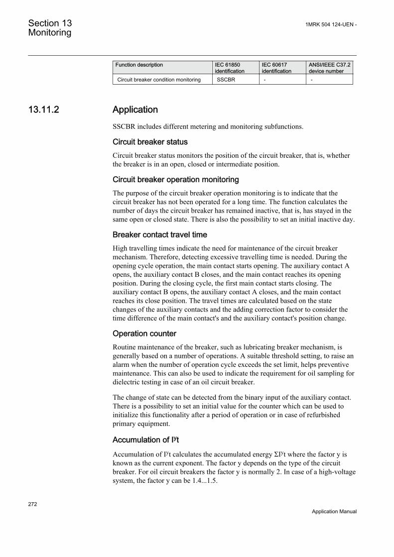
Function description IEC 61850identification
IEC 60617identification
ANSI/IEEE C37.2device number
Circuit breaker condition monitoring SSCBR - -
13.11.2 ApplicationSSCBR includes different metering and monitoring subfunctions.
Circuit breaker statusCircuit breaker status monitors the position of the circuit breaker, that is, whetherthe breaker is in an open, closed or intermediate position.
Circuit breaker operation monitoringThe purpose of the circuit breaker operation monitoring is to indicate that thecircuit breaker has not been operated for a long time. The function calculates thenumber of days the circuit breaker has remained inactive, that is, has stayed in thesame open or closed state. There is also the possibility to set an initial inactive day.
Breaker contact travel timeHigh travelling times indicate the need for maintenance of the circuit breakermechanism. Therefore, detecting excessive travelling time is needed. During theopening cycle operation, the main contact starts opening. The auxiliary contact Aopens, the auxiliary contact B closes, and the main contact reaches its openingposition. During the closing cycle, the first main contact starts closing. Theauxiliary contact B opens, the auxiliary contact A closes, and the main contactreaches its close position. The travel times are calculated based on the statechanges of the auxiliary contacts and the adding correction factor to consider thetime difference of the main contact's and the auxiliary contact's position change.
Operation counterRoutine maintenance of the breaker, such as lubricating breaker mechanism, isgenerally based on a number of operations. A suitable threshold setting, to raise analarm when the number of operation cycle exceeds the set limit, helps preventivemaintenance. This can also be used to indicate the requirement for oil sampling fordielectric testing in case of an oil circuit breaker.
The change of state can be detected from the binary input of the auxiliary contact.There is a possibility to set an initial value for the counter which can be used toinitialize this functionality after a period of operation or in case of refurbishedprimary equipment.
Accumulation of Iyt
Accumulation of Iyt calculates the accumulated energy ΣIyt where the factor y isknown as the current exponent. The factor y depends on the type of the circuitbreaker. For oil circuit breakers the factor y is normally 2. In case of a high-voltagesystem, the factor y can be 1.4...1.5.
Section 13 1MRK 504 124-UEN -Monitoring
272Application Manual
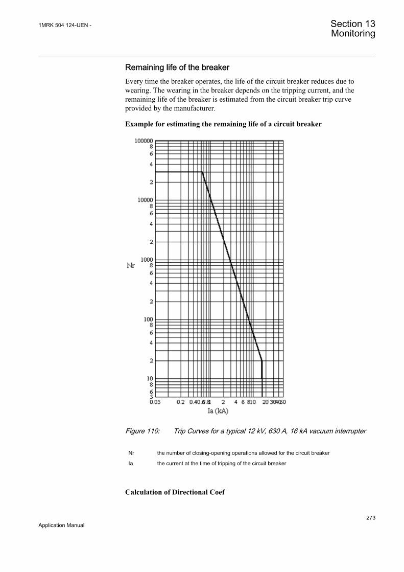
Remaining life of the breakerEvery time the breaker operates, the life of the circuit breaker reduces due towearing. The wearing in the breaker depends on the tripping current, and theremaining life of the breaker is estimated from the circuit breaker trip curveprovided by the manufacturer.
Example for estimating the remaining life of a circuit breaker
A071114 V3 EN
Figure 110: Trip Curves for a typical 12 kV, 630 A, 16 kA vacuum interrupter
Nr the number of closing-opening operations allowed for the circuit breaker
Ia the current at the time of tripping of the circuit breaker
Calculation of Directional Coef
1MRK 504 124-UEN - Section 13Monitoring
273Application Manual

The directional coefficient is calculated according to the formula:
Directional Coef
B
A
I
I
f
r
=
= −log
log
.2 2609
A070794 V2 EN (Equation 96)
Ir Rated operating current = 630 A
If Rated fault current = 16 kA
A Op number rated = 30000
B Op number fault = 20
Calculation for estimating the remaining life
The equation shows that there are 30,000 possible operations at the rated operatingcurrent of 630 A and 20 operations at the rated fault current 16 kA. Therefore, ifthe tripping current is 10 kA, one operation at 10 kA is equivalent to30,000/500=60 operations at the rated current. It is also assumed that prior to thistripping, the remaining life of the circuit breaker is 15,000 operations. Therefore,after one operation of 10 kA, the remaining life of the circuit breaker is15,000-60=14,940 at the rated operating current.
Spring charged indicationFor normal operation of the circuit breaker, the circuit breaker spring should becharged within a specified time. Therefore, detecting long spring charging timeindicates that it is time for the circuit breaker maintenance. The last value of thespring charging time can be used as a service value.
Gas pressure supervisionThe gas pressure supervision monitors the gas pressure inside the arc chamber.When the pressure becomes too low compared to the required value, the circuitbreaker operations are locked. A binary input is available based on the pressurelevels in the function, and alarms are generated based on these inputs.
Section 13 1MRK 504 124-UEN -Monitoring
274Application Manual
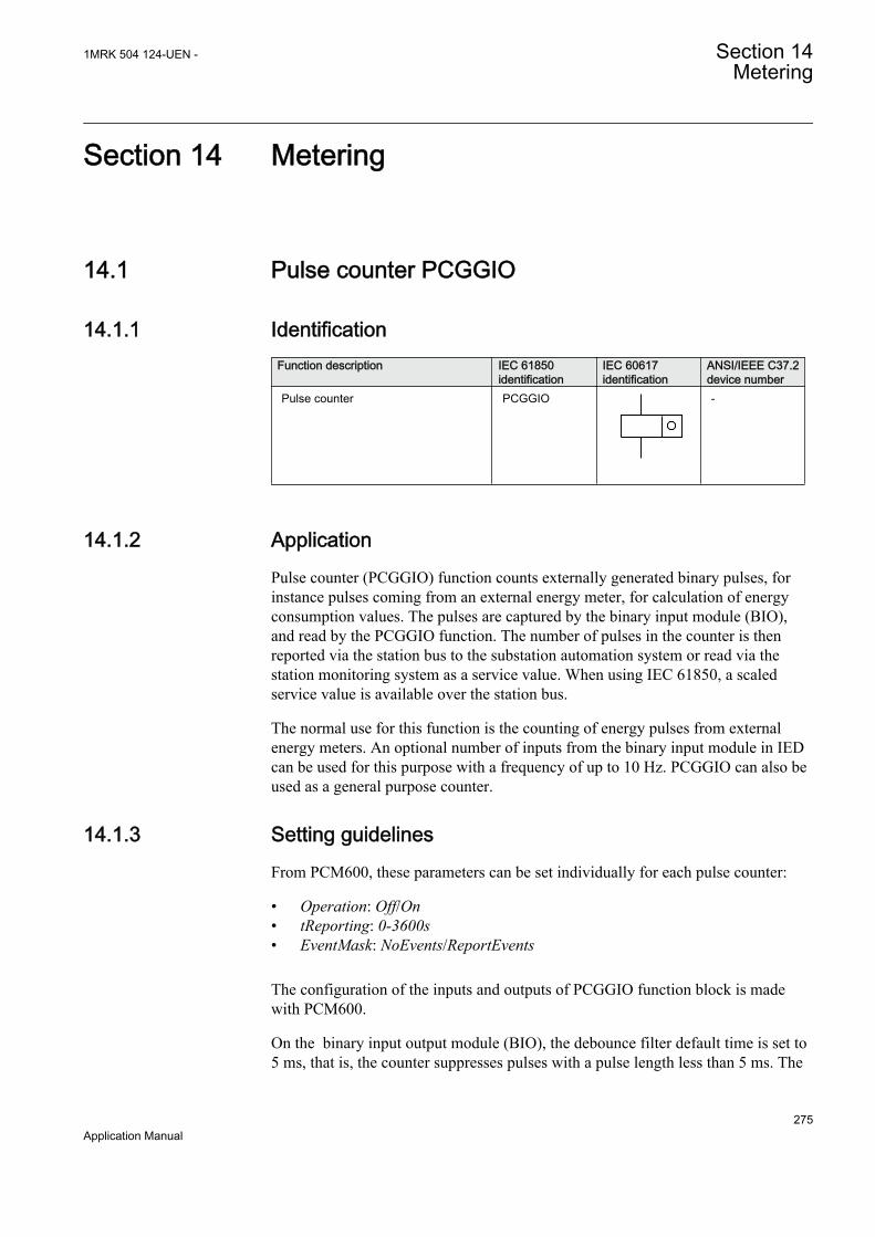
Section 14 Metering
14.1 Pulse counter PCGGIO
14.1.1 IdentificationFunction description IEC 61850
identificationIEC 60617identification
ANSI/IEEE C37.2device number
Pulse counter PCGGIO
S00947 V1 EN
-
14.1.2 ApplicationPulse counter (PCGGIO) function counts externally generated binary pulses, forinstance pulses coming from an external energy meter, for calculation of energyconsumption values. The pulses are captured by the binary input module (BIO),and read by the PCGGIO function. The number of pulses in the counter is thenreported via the station bus to the substation automation system or read via thestation monitoring system as a service value. When using IEC 61850, a scaledservice value is available over the station bus.
The normal use for this function is the counting of energy pulses from externalenergy meters. An optional number of inputs from the binary input module in IEDcan be used for this purpose with a frequency of up to 10 Hz. PCGGIO can also beused as a general purpose counter.
14.1.3 Setting guidelinesFrom PCM600, these parameters can be set individually for each pulse counter:
• Operation: Off/On• tReporting: 0-3600s• EventMask: NoEvents/ReportEvents
The configuration of the inputs and outputs of PCGGIO function block is madewith PCM600.
On the binary input output module (BIO), the debounce filter default time is set to5 ms, that is, the counter suppresses pulses with a pulse length less than 5 ms. The
1MRK 504 124-UEN - Section 14Metering
275Application Manual
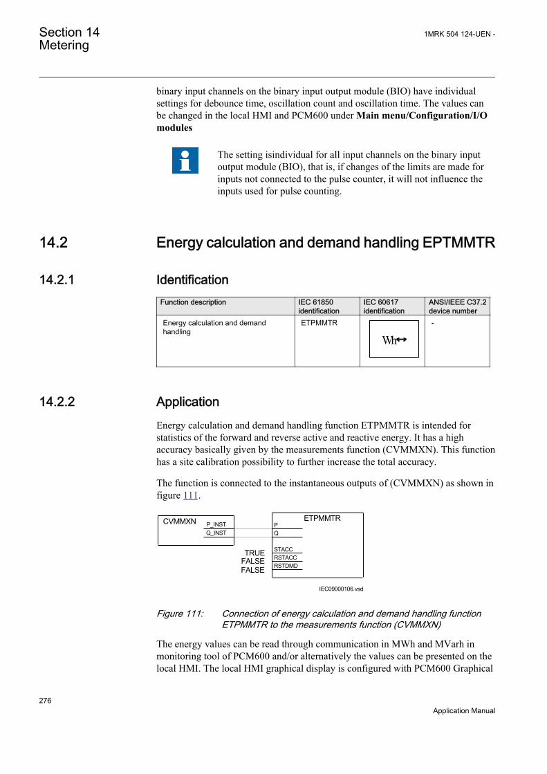
binary input channels on the binary input output module (BIO) have individualsettings for debounce time, oscillation count and oscillation time. The values canbe changed in the local HMI and PCM600 under Main menu/Configuration/I/Omodules
The setting isindividual for all input channels on the binary inputoutput module (BIO), that is, if changes of the limits are made forinputs not connected to the pulse counter, it will not influence theinputs used for pulse counting.
14.2 Energy calculation and demand handling EPTMMTR
14.2.1 IdentificationFunction description IEC 61850
identificationIEC 60617identification
ANSI/IEEE C37.2device number
Energy calculation and demandhandling
ETPMMTR
WhIEC10000169 V1 EN
-
14.2.2 ApplicationEnergy calculation and demand handling function ETPMMTR is intended forstatistics of the forward and reverse active and reactive energy. It has a highaccuracy basically given by the measurements function (CVMMXN). This functionhas a site calibration possibility to further increase the total accuracy.
The function is connected to the instantaneous outputs of (CVMMXN) as shown infigure 111.
PQ
STACCRSTACCRSTDMD
TRUEFALSEFALSE
CVMMXN
IEC09000106.vsd
ETPMMTRP_INSTQ_INST
IEC09000106 V1 EN
Figure 111: Connection of energy calculation and demand handling functionETPMMTR to the measurements function (CVMMXN)
The energy values can be read through communication in MWh and MVarh inmonitoring tool of PCM600 and/or alternatively the values can be presented on thelocal HMI. The local HMI graphical display is configured with PCM600 Graphical
Section 14 1MRK 504 124-UEN -Metering
276Application Manual

display editor tool (GDE) with a measuring value which is selected to the activeand reactive component as preferred. All four values can also be presented.
Maximum demand values are presented in MWh or MVarh in the same way.
Alternatively, the values can be presented with use of the pulse counters function(PCGGIO). The output values are scaled with the pulse output setting valuesEAFAccPlsQty, EARAccPlsQty, ERFAccPlsQty and ERRAccPlsQty of the energymetering function and then the pulse counter can be set-up to present the correctvalues by scaling in this function. Pulse counter values can then be presented onthe local HMI in the same way and/or sent to the SA system throughcommunication where the total energy then is calculated by summation of theenergy pulses. This principle is good for very high values of energy as thesaturation of numbers else will limit energy integration to about one year with 50kV and 3000 A. After that the accumulation will start on zero again.
14.2.3 Setting guidelinesThe parameters are set via the local HMI or PCM600.
The following settings can be done for the energy calculation and demand handlingfunction ETPMMTR:
Common base IED values for primary current (IBase), primary voltage (UBase)and primary power (SBase) are set in a Global base values for settings functionGBASVAL. Setting GlobalBaseSel is used to select a GBASVAL function forreference of base values.
Operation: Off/On
tEnergy: Time interval when energy is measured.
StartAcc: Off/On is used to switch the accumulation of energy on and off.
The input signal STACC is used to start accumulation. Input signalSTACC cannot be used to halt accumulation. The energy content isreset every time STACC is activated. STACC can for example, beused when an external clock is used to switch two active energymeasuring function blocks on and off to have indication of two tariffs.
tEnergyOnPls: gives the pulse length ON time of the pulse. It should be at least100 ms when connected to the Pulse counter function block. Typical value can be100 ms.
tEnergyOffPls: gives the OFF time between pulses. Typical value can be 100 ms.
EAFAccPlsQty and EARAccPlsQty: gives the MWh value in each pulse. It shouldbe selected together with the setting of the Pulse counter (PCGGIO) settings togive the correct total pulse value.
1MRK 504 124-UEN - Section 14Metering
277Application Manual

ERFAccPlsQty and ERRAccPlsQty: gives the MVarh value in each pulse. It shouldbe selected together with the setting of the Pulse counter (PCGGIO) settings togive the correct total pulse value.
For the advanced user there are a number of settings for direction, zero clamping,max limit, and so on. Normally, the default values are suitable for these parameters.
Section 14 1MRK 504 124-UEN -Metering
278Application Manual

Section 15 Station communication
15.1 IEC61850-8-1 communication protocol
15.1.1 IdentificationFunction description IEC 61850
identificationIEC 60617identification
ANSI/IEEE C37.2device number
IEC 61850-8-1 communication protocol IEC 61850-8-1 - -
15.1.2 ApplicationIEC 61850-8-1 communication protocol allows vertical communication to HSIclients and allows horizontal communication between two or more intelligentelectronic devices (IEDs) from one or several vendors to exchange information andto use it in the performance of their functions and for correct co-operation.
GOOSE (Generic Object Oriented Substation Event), which is a part of IEC 61850–8–1 standard, allows the IEDs to communicate state and control informationamongst themselves, using a publish-subscribe mechanism. That is, upon detectingan event, the IED(s) use a multi-cast transmission to notify those devices that haveregistered to receive the data. An IED can, by publishing a GOOSE message,report its status. It can also request a control action to be directed at any device inthe network.
Figure 112 shows the topology of an IEC 61850–8–1 configuration. IEC 61850–8–1 specifies only the interface to the substation LAN. The LAN itself is left to thesystem integrator.
1MRK 504 124-UEN - Section 15Station communication
279Application Manual

KIOSK 2 KIOSK 3
Station HSIBase System
EngineeringWorkstation
SMSGateway
Printer
CC
IEC09000135_en.vsd
KIOSK 1
IED 1
IED 2
IED 3
IED 1
IED 2
IED 3
IED 1
IED 2
IED 3
IEC09000135 V1 EN
Figure 112: Example of a communication system with IEC 61850
Figure 113 shows the GOOSE peer-to-peer communication.
Control Protection Control ProtectionControl and protection
GOOSE
en05000734.vsd
Station HSIMicroSCADA
Gateway
IEDA
IEDA
IEDA
IEDA
IEDA
IEC05000734 V1 EN
Figure 113: Example of a broadcasted GOOSE message
Section 15 1MRK 504 124-UEN -Station communication
280Application Manual

15.1.2.1 Horizontal communication via GOOSE
GOOSE messages are sent in horizontal communication between the IEDs. Theinformation, which is exchanged, is used for station wide interlocking, breakerfailure protection, busbar voltage selection and so on.
The simplified principle is shown in Figure 114 and can be described as follows.When IED1 has decided to transmit the data set it forces a transmission via thestation bus. All other IEDs will receive the data set, but only those who have thisdata set in their address list will take it and keeps it in a input container. It isdefined, that the receiving IED will take the content of the received data set andmakes it available for the application configuration.
IEC08000145.vsd
IED1 IED3IED2
DO1/DA1DO1/DA2DO2/DA1DO2/DA2DO3/DA1DO3/DA2
IED1IED1IED1IED1IED1IED1
SMT
Receive-FB
DA1DA2DO1
DA1DA2DA1DA2DO3
DA1DA2DO2
Stationbus
DO1/DA1DO1/DA2DO2/DA1DO2/DA2DO3/DA1DO3/DA2
IED1IED1IED1IED1IED1IED1
PLC Program
FBa FBb FBc
IEC08000145 V1 EN
Figure 114: SMT: GOOSE principle and signal routing with SMT
Special function blocks take the data set and present it via the function block asoutput signals for application functions in the application configuration. DifferentGOOSE receive function blocks are available for the specific tasks.
SMT links the different data object attributes (for example stVal or magnitude) tothe output signal to make it available for functions in the application configuration.When a matrix cell array is marked red the IEC 61850 data attribute type does notfit together, even if the GOOSE receive function block is the partner. SMT checksthis on the content of the received data set. See Figure 115
1MRK 504 124-UEN - Section 15Station communication
281Application Manual
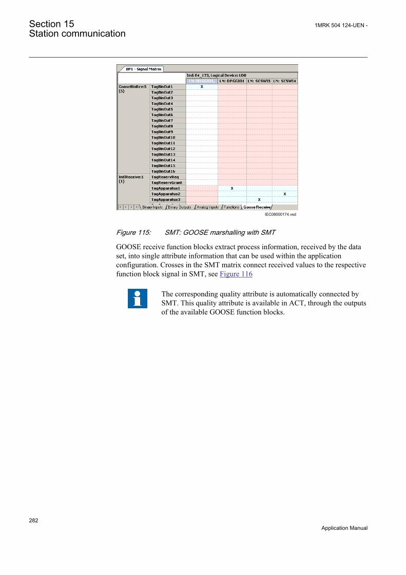
IEC08000174.vsdIEC08000174 V1 EN
Figure 115: SMT: GOOSE marshalling with SMT
GOOSE receive function blocks extract process information, received by the dataset, into single attribute information that can be used within the applicationconfiguration. Crosses in the SMT matrix connect received values to the respectivefunction block signal in SMT, see Figure 116
The corresponding quality attribute is automatically connected bySMT. This quality attribute is available in ACT, through the outputsof the available GOOSE function blocks.
Section 15 1MRK 504 124-UEN -Station communication
282Application Manual
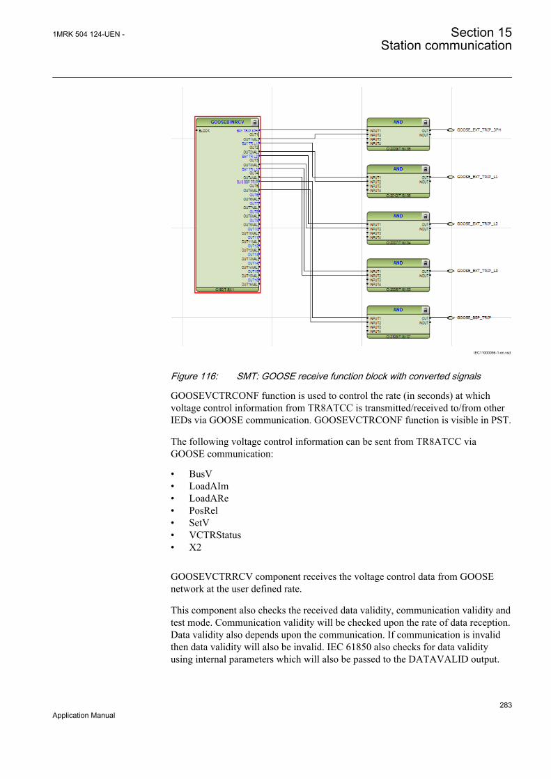
IEC11000056-1-en.vsd
IEC11000056 V1 EN
Figure 116: SMT: GOOSE receive function block with converted signals
GOOSEVCTRCONF function is used to control the rate (in seconds) at whichvoltage control information from TR8ATCC is transmitted/received to/from otherIEDs via GOOSE communication. GOOSEVCTRCONF function is visible in PST.
The following voltage control information can be sent from TR8ATCC viaGOOSE communication:
• BusV• LoadAIm• LoadARe• PosRel• SetV• VCTRStatus• X2
GOOSEVCTRRCV component receives the voltage control data from GOOSEnetwork at the user defined rate.
This component also checks the received data validity, communication validity andtest mode. Communication validity will be checked upon the rate of data reception.Data validity also depends upon the communication. If communication is invalidthen data validity will also be invalid. IEC 61850 also checks for data validityusing internal parameters which will also be passed to the DATAVALID output.
1MRK 504 124-UEN - Section 15Station communication
283Application Manual
15.1.3 Setting guidelinesThere are two settings related to the IEC 61850–8–1 protocol:
Operation User can set IEC 61850 communication to On or Off.
GOOSE has to be set to the Ethernet link where GOOSE traffic shall be send andreceived.
IEC 61850–8–1 specific data (logical nodes etc.) per includedfunction in an IED can be found in the communication protocolmanual for IEC 61850.
The setting parameters for GOOSEVCTRCONF are described below:
SendOperation: This setting sets the send functionality ON or OFF.
ReceiveOperation: This setting sets the receive functionality ON or OFF.
SendInterval: This parameter sets the rate at which VCTR Send component need totransmit the GOOSE message over network. Default value of the send interval is0.3s. Minimum value of the send interval can be set to 0.1s and maximum as 5.0s.
ReceiveInterval: This parameter sets the rate at which VCTR receive componentneed to receive the GOOSE message from the network. Default value of thereceive interval is 0.8s. Minimum value of the send interval can be set to 0.1s andmaximum as 10.0s
Receive interval should be greater than the send interval. With thisconfiguration receiving component shall always have the updatedvalue. For example ReceiveInterval > 2•SendInterval.
15.2 DNP3 protocol
DNP3 (Distributed Network Protocol) is a set of communications protocols used tocommunicate data between components in process automation systems. For adetailed description of the DNP3 protocol, see the DNP3 Communication protocolmanual.
15.3 IEC 60870-5-103 communication protocol
IEC 60870-5-103 is an unbalanced (master-slave) protocol for coded-bit serialcommunication exchanging information with a control system, and with a datatransfer rate up to 38400 bit/s. In IEC terminology, a primary station is a master
Section 15 1MRK 504 124-UEN -Station communication
284Application Manual

and a secondary station is a slave. The communication is based on a point-to-pointprinciple. The master must have software that can interpret IEC 60870-5-103communication messages.
The Communication protocol manual for IEC 60870-5-103 includes the 650 seriesvendor specific IEC 60870-5-103 implementation.
1MRK 504 124-UEN - Section 15Station communication
285Application Manual

286

Section 16 Basic IED functions
16.1 Self supervision with internal event list
16.1.1 IdentificationFunction description IEC 61850
identificationIEC 60617identification
ANSI/IEEE C37.2device number
Internal error signal INTERRSIG - -
Internal event list SELFSUPEVLST - -
16.1.2 ApplicationThe protection and control IEDs have many included functions. Self supervisionwith internal event list (SELFSUPEVLST) and internal error signals(INTERRSIG) function provide supervision of the IED. The fault signals make iteasier to analyze and locate a fault.
Both hardware and software supervision is included and it is also possible toindicate possible faults through a hardware contact on the power supply module and/or through the software communication.
Internal events are generated by the built-in supervisory functions. The supervisoryfunctions supervise the status of the various modules in the IED and, in case offailure, a corresponding event is generated. Similarly, when the failure is corrected,a corresponding event is generated.
Apart from the built-in supervision of the various modules, events are alsogenerated when the status changes for the:
• built-in real time clock (in operation/out of order).• external time synchronization (in operation/out of order).• Change lock (on/off)
Events are also generated:
• whenever any setting in the IED is changed.
The internal events are time tagged with a resolution of 1 ms and stored in a list.The list can store up to 40 events. The list is based on the FIFO principle, that is,when it is full, the oldest event is overwritten. The list can be cleared via the localHMI .
1MRK 504 124-UEN - Section 16Basic IED functions
287Application Manual
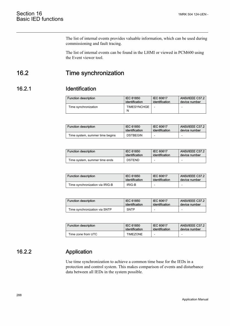
The list of internal events provides valuable information, which can be used duringcommissioning and fault tracing.
The list of internal events can be found in the LHMI or viewed in PCM600 usingthe Event viewer tool.
16.2 Time synchronization
16.2.1 IdentificationFunction description IEC 61850
identificationIEC 60617identification
ANSI/IEEE C37.2device number
Time synchronization TIMESYNCHGEN
- -
Function description IEC 61850identification
IEC 60617identification
ANSI/IEEE C37.2device number
Time system, summer time begins DSTBEGIN - -
Function description IEC 61850identification
IEC 60617identification
ANSI/IEEE C37.2device number
Time system, summer time ends DSTEND - -
Function description IEC 61850identification
IEC 60617identification
ANSI/IEEE C37.2device number
Time synchronization via IRIG-B IRIG-B - -
Function description IEC 61850identification
IEC 60617identification
ANSI/IEEE C37.2device number
Time synchronization via SNTP SNTP - -
Function description IEC 61850identification
IEC 60617identification
ANSI/IEEE C37.2device number
Time zone from UTC TIMEZONE - -
16.2.2 ApplicationUse time synchronization to achieve a common time base for the IEDs in aprotection and control system. This makes comparison of events and disturbancedata between all IEDs in the system possible.
Section 16 1MRK 504 124-UEN -Basic IED functions
288Application Manual

Time-tagging of internal events and disturbances are an excellent help whenevaluating faults. Without time synchronization, only the events within the IED canbe compared to one another. With time synchronization, events and disturbanceswithin the entire station, and even between line ends, can be compared at evaluation.
In the IED, the internal time can be synchronized from a number of sources:
• SNTP• IRIG-B• DNP• IEC60870-5-103
Micro SCADA OPC server should not be used as a timesynchronization source.
16.2.3 Setting guidelines
System timeThe time is set with years, month, day, hour, minute and second.
SynchronizationThe setting parameters for the real-time clock with external time synchronization(TIME) are set via local HMI or PCM600.
TimeSynchWhen the source of the time synchronization is selected on the local HMI, theparameter is called TimeSynch. The time synchronization source can also be setfrom PCM600. The setting alternatives are:
FineSyncSource which can have the following values:
• Off• SNTP• IRIG-B
CoarseSyncSrc which can have the following values:
• Off• SNTP• DNP• IEC60870-5-103
The system time can be set manually, either via the local HMI or via any of thecommunication ports. The time synchronization fine tunes the clock.
1MRK 504 124-UEN - Section 16Basic IED functions
289Application Manual
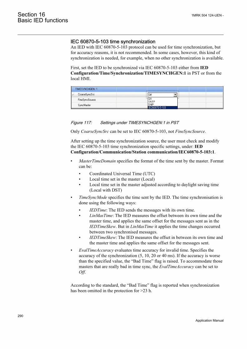
IEC 60870-5-103 time synchronizationAn IED with IEC 60870-5-103 protocol can be used for time synchronization, butfor accuracy reasons, it is not recommended. In some cases, however, this kind ofsynchronization is needed, for example, when no other synchronization is available.
First, set the IED to be synchronized via IEC 60870-5-103 either from IEDConfiguration/Time/Synchronization/TIMESYNCHGEN:1 in PST or from thelocal HMI.
GUID-68284E7B-A24D-4E78-B5BA-736B29F50E9A V1 EN
Figure 117: Settings under TIMESYNCHGEN:1 in PST
Only CoarseSyncSrc can be set to IEC 60870-5-103, not FineSyncSource.
After setting up the time synchronization source, the user must check and modifythe IEC 60870-5-103 time synchronization specific settings, under: IEDConfiguration/Communication/Station communication/IEC60870-5-103:1.
• MasterTimeDomain specifies the format of the time sent by the master. Formatcan be:• Coordinated Universal Time (UTC)• Local time set in the master (Local)• Local time set in the master adjusted according to daylight saving time
(Local with DST)• TimeSyncMode specifies the time sent by the IED. The time synchronisation is
done using the following ways:• IEDTime: The IED sends the messages with its own time.• LinMasTime: The IED measures the offset between its own time and the
master time, and applies the same offset for the messages sent as in theIEDTimeSkew. But in LinMasTime it applies the time changes occurredbetween two synchronised messages.
• IEDTimeSkew: The IED measures the offset in between its own time andthe master time and applies the same offset for the messages sent.
• EvalTimeAccuracy evaluates time accuracy for invalid time. Specifies theaccuracy of the synchronization (5, 10, 20 or 40 ms). If the accuracy is worsethan the specified value, the “Bad Time” flag is raised. To accommodate thosemasters that are really bad in time sync, the EvalTimeAccuracy can be set toOff.
According to the standard, the “Bad Time” flag is reported when synchronizationhas been omitted in the protection for >23 h.
Section 16 1MRK 504 124-UEN -Basic IED functions
290Application Manual
16.3 Parameter setting group handling
16.3.1 IdentificationFunction description IEC 61850
identificationIEC 60617identification
ANSI/IEEE C37.2device number
Setting group handling SETGRPS - -
Parameter setting groups ACTVGRP - -
16.3.2 ApplicationFour sets of settings are available to optimize IED operation for different systemconditions. By creating and switching between fine tuned setting sets, either fromthe local HMI or configurable binary inputs, results in a highly adaptable IED thatcan cope with a variety of system scenarios.
Different conditions in networks with different voltage levels require highlyadaptable protection and control units to best provide for dependability, securityand selectivity requirements. Protection units operate with a higher degree ofavailability, especially, if the setting values of their parameters are continuouslyoptimized according to the conditions in the power system.
Operational departments can plan for different operating conditions in the primaryequipment. The protection engineer can prepare the necessary optimized and pre-tested settings in advance for different protection functions. Four different groupsof setting parameters are available in the IED. Any of them can be activatedthrough the different programmable binary inputs by means of external or internalcontrol signals.
16.3.3 Setting guidelinesThe setting ActiveSetGrp, is used to select which parameter group to be active. Theactive group can also be selected with configured input to the function blockACTVGRP.
The parameter MaxNoSetGrp defines the maximum number of setting groups inuse to switch between. Only the selected number of setting groups will be availablein the Parameter Setting tool (PST) for activation with the ACTVGRP function block.
1MRK 504 124-UEN - Section 16Basic IED functions
291Application Manual
16.4 Test mode functionality TESTMODE
16.4.1 IdentificationFunction description IEC 61850
identificationIEC 60617identification
ANSI/IEEE C37.2device number
Test mode functionality TESTMODE - -
16.4.2 ApplicationThe protection and control IEDs have a complex configuration with many includedfunctions. To make the testing procedure easier, the IEDs include the feature thatallows individual blocking of a single-, several-, or all functions.
This means that it is possible to see when a function is activated or trips. It alsoenables the user to follow the operation of several related functions to checkcorrect functionality and to check parts of the configuration, and so on.
16.4.3 Setting guidelinesRemember always that there are two possible ways to place the IED in the “Testmode: On” state. If, the IED is set to normal operation (TestMode = Off), but thefunctions are still shown being in the test mode, the input signal INPUT on theTESTMODE function block might be activated in the configuration.
Forcing of binary output signals is only possible when the IED is in test mode.
16.5 Change lock CHNGLCK
16.5.1 IdentificationFunction description IEC 61850
identificationIEC 60617identification
ANSI/IEEE C37.2device number
Change lock function CHNGLCK - -
16.5.2 ApplicationChange lock function CHNGLCK is used to block further changes to the IEDconfiguration once the commissioning is complete. The purpose is to make itimpossible to perform inadvertent IED configuration changes beyond a certainpoint in time.
Section 16 1MRK 504 124-UEN -Basic IED functions
292Application Manual
However, when activated, CHNGLCK will still allow the following changes of theIED state that does not involve reconfiguring of the IED:
• Monitoring• Reading events• Resetting events• Reading disturbance data• Clear disturbances• Reset LEDs• Reset counters and other runtime component states• Control operations• Set system time• Enter and exit from test mode• Change of active setting group
The binary input controlling the function is defined in ACT or SMT. TheCHNGLCK function is configured using ACT.
LOCK Binary input signal that will activate/deactivate the function, defined in ACT orSMT.
ACTIVE Output status signal
OVERRIDE Set if function is overridden
When CHNGLCK has a logical one on its input, then all attempts to modify theIED configuration will be denied and the message "Error: Changes blocked" willbe displayed on the local HMI; in PCM600 the message will be "Operation deniedby active ChangeLock". The CHNGLCK function should be configured so that it iscontrolled by a signal from a binary input card. This guarantees that by setting thatsignal to a logical zero, CHNGLCK is deactivated. If any logic is included in thesignal path to the CHNGLCK input, that logic must be designed so that it cannotpermanently issue a logical one on the CHNGLCK input. If such a situation wouldoccur in spite of these precautions, then please contact the local ABBrepresentative for remedial action.
16.5.3 Setting guidelinesThe Change lock function CHNGLCK does not have any parameters available inthe local HMI or PCM600.
1MRK 504 124-UEN - Section 16Basic IED functions
293Application Manual

16.6 IED identifiers TERMINALID
16.6.1 IdentificationFunction description IEC 61850
identificationIEC 60617identification
ANSI/IEEE C37.2device number
IED identifiers TERMINALID - -
16.6.2 Application
16.6.2.1 Customer specific settings
The customer specific settings are used to give the IED a unique name and address.The settings are used by a central control system to communicate with the IED.The customer specific identifiers are found in the local HMI under Configuration/Power system/Identifiers/TERMINALID
The settings can also be made from PCM600. For more information about theavailable identifiers, see the technical manual.
Use only characters A - Z, a - z and 0 - 9 in station, unit and objectnames.
16.7 Product information PRODINF
16.7.1 IdentificationFunction description IEC 61850
identificationIEC 60617identification
ANSI/IEEE C37.2device number
Product information PRODINF - -
16.7.2 Application
16.7.2.1 Factory defined settings
The factory defined settings are very useful for identifying a specific version andvery helpful in the case of maintenance, repair, interchanging IEDs betweendifferent Substation Automation Systems and upgrading. The factory made settingscan not be changed by the customer. They can only be viewed. The settings arefound in the local HMI under Main menu/Diagnostics/IED status/Productidentifiers
Section 16 1MRK 504 124-UEN -Basic IED functions
294Application Manual

The following identifiers are available:
• IEDProdType• Describes the type of the IED (like REL, REC or RET. Example: REL650
• ProductDef• Describes the release number, from the production. Example: 1.1.0.A1
• ProductVer• Describes the product version. Example: 1.1.0
• SerialNo• OrderingNo• ProductionDate
16.8 Primary system values PRIMVAL
16.8.1 IdentificationFunction description IEC 61850
identificationIEC 60617identification
ANSI/IEEE C37.2device number
Primary system values PRIMVAL - -
16.8.2 ApplicationThe rated system frequency and phasor rotation are set under Main menu/Configuration/ Power system/ Primary values/PRIMVAL in the local HMI andPCM600 parameter setting tree.
16.9 Signal matrix for analog inputs SMAI
16.9.1 IdentificationFunction description IEC 61850
identificationIEC 60617identification
ANSI/IEEE C37.2device number
Signal matrix for analog inputs SMAI_20_1 - -
16.9.2 ApplicationSignal matrix for analog inputs function SMAI (or the pre-processing function) isused within PCM600 in direct relation with the Signal Matrix tool or theApplication Configuration tool. Signal Matrix tool represents the way analoginputs are brought in for one IED configuration.
1MRK 504 124-UEN - Section 16Basic IED functions
295Application Manual
16.9.3 Setting guidelinesThe parameters for the signal matrix for analog inputs (SMAI) functions are set viathe local HMI, PCM600.
Every SMAI function block can receive four analog signals (three phases and oneneutral value), either voltage or current. SMAI outputs give information aboutevery aspect of the 3ph analog signals acquired (phase angle, RMS value,frequency and frequency derivates, and so on – 244 values in total). Besides theblock “group name”, the analog inputs type (voltage or current) and the analoginput names that can be set directly in ACT.
Common base IED values for primary current (IBase), primary voltage (UBase)and primary power (SBase) are set in a Global base values for settings functionGBASVAL. Setting GlobalBaseSel is used to select a GBASVAL function forreference of base values.
DFTRefExtOut: Parameter valid for function block SMAI_20_1:1, SMAI_20_1:2and SMAI_80_1 only. Reference block for external output (SPFCOUT functionoutput).
DFTReference: Reference DFT for the block.
These DFT reference block settings decide DFT reference for DFT calculations(InternalDFTRef will use fixed DFT reference based on set system frequency.DFTRefGrpn will use DFT reference from the selected group block, when owngroup selected adaptive DFT reference will be used based on calculated signalfrequency from own group.ExternalDFTRef will use reference based on inputDFTSPFC.
ConnectionType: Connection type for that specific instance (n) of the SMAI (if it isPh-N or Ph-Ph). Depending on connection type setting the not connected Ph-N orPh-Ph outputs will be calculated.
Negation: If the user wants to negate the 3ph signal, it is possible to choose tonegate only the phase signals Negate3Ph, only the neutral signal NegateN or bothNegate3Ph+N; negation means rotation with 180° of the vectors.
MinValFreqMeas: The minimum value of the voltage for which the frequency iscalculated, expressed as percent of GlobeBasUaGrp(n) (for each instance n).
Settings DFTRefExtOut and DFTReference shall be set to defaultvalue InternalDFTRef if no VT inputs are available.
Example of adaptive frequency tracking
Section 16 1MRK 504 124-UEN -Basic IED functions
296Application Manual
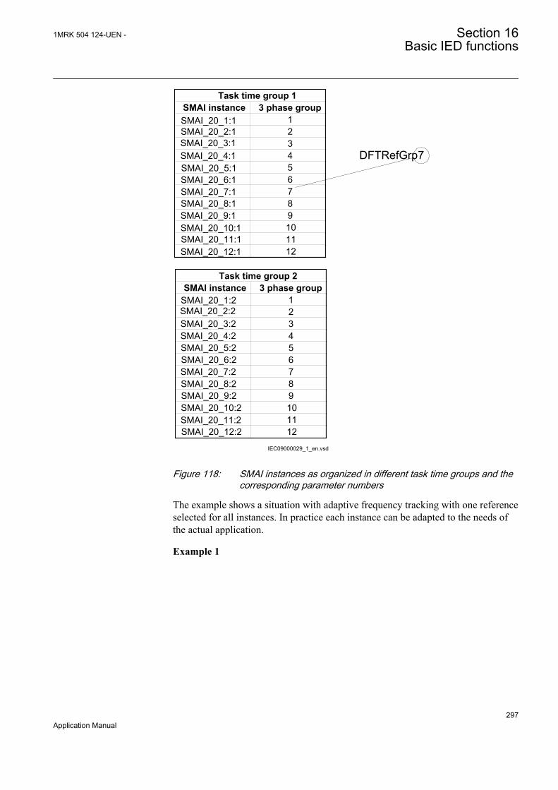
IEC09000029_1_en.vsd
SMAI instance 3 phase groupSMAI_20_1:1 1SMAI_20_2:1 2SMAI_20_3:1 3SMAI_20_4:1 4SMAI_20_5:1 5SMAI_20_6:1 6SMAI_20_7:1 7SMAI_20_8:1 8SMAI_20_9:1 9SMAI_20_10:1 10SMAI_20_11:1 11SMAI_20_12:1 12
Task time group 1
SMAI instance 3 phase groupSMAI_20_1:2 1SMAI_20_2:2 2SMAI_20_3:2 3SMAI_20_4:2 4SMAI_20_5:2 5SMAI_20_6:2 6SMAI_20_7:2 7SMAI_20_8:2 8SMAI_20_9:2 9SMAI_20_10:2 10SMAI_20_11:2 11SMAI_20_12:2 12
Task time group 2
DFTRefGrp7
IEC09000029 V1 EN
Figure 118: SMAI instances as organized in different task time groups and thecorresponding parameter numbers
The example shows a situation with adaptive frequency tracking with one referenceselected for all instances. In practice each instance can be adapted to the needs ofthe actual application.
Example 1
1MRK 504 124-UEN - Section 16Basic IED functions
297Application Manual

SMAI_20_7:1BLOCKDFTSPFCREVROTAI1NAMEAI2NAMEAI3NAMEAI4NAME
SPFCOUTAI3P
AI1AI2AI3AI4AIN
SMAI_20_1-12:2BLOCKDFTSPFCREVROTAI1NAMEAI2NAMEAI3NAMEAI4NAME
SPFCOUTAI3P
AI1AI2AI3AI4AIN
IEC09000028-1.vsd
Task time group 1 Task time group 2
IEC09000028 V1 EN
Figure 119: Configuration for using an instance in task time group 1 as DFTreference
Assume instance SMAI_20_7:1 in task time group 1 has been selected in theconfiguration to control the frequency tracking (For the SMAI_20_x task timegroups). Observe that the selected reference instance must be a voltage type.
For task time group 1 this gives the following settings (see Figure 118 for numbering):
SMAI_20_7:1: DFTRefExtOut = DFTRefGrp7 to route SMAI_20_7:1 reference tothe SPFCOUT output, DFTReference = DFTRefGrp7 for SMAI_20_7:1 to useSMAI_20_7:1 as reference (see Figure 119). .
SMAI_20_2:1 - SMAI_20_12:1 DFTReference = DFTRefGrp7 for SMAI_20_2:1 -SMAI_20_12:1 to use SMAI_20_7:1 as reference.
For task time group 2 this gives the following settings:
SMAI_20_1:2 - SMAI_20_12:2 DFTReference = ExternalDFTRef to useDFTSPFC input as reference (SMAI_20_7:1)
16.10 Summation block 3 phase 3PHSUM
16.10.1 IdentificationFunction description IEC 61850
identificationIEC 60617identification
ANSI/IEEE C37.2device number
Summation block 3 phase 3PHSUM - -
16.10.2 ApplicationSummation block 3 phase function 3PHSUM is used to get the sum of two sets ofthree-phase analog signals (of the same type) for those IED functions that mightneed it.
Section 16 1MRK 504 124-UEN -Basic IED functions
298Application Manual
16.10.3 Setting guidelinesThe summation block receives the three-phase signals from SMAI blocks. Thesummation block has several settings.
Common base IED values for primary current (IBase), primary voltage (UBase)and primary power (SBase) are set in a Global base values for settings functionGBASVAL. Setting GlobalBaseSel is used to select a GBASVAL function forreference of base values.
SummationType: Summation type (Group 1 + Group 2, Group 1 - Group 2, Group2 - Group 1 or –(Group 1 + Group 2)).
DFTReference: The reference DFT block (InternalDFT Ref,DFTRefGrp1 orExternal DFT ref) .
FreqMeasMinVal: The minimum value of the voltage for which the frequency iscalculated, expressed as percent of UBase (for each instance x).
16.11 Global base values GBASVAL
16.11.1 IdentificationFunction description IEC 61850
identificationIEC 60617identification
ANSI/IEEE C37.2device number
Global base values GBASVAL - -
16.11.2 ApplicationGlobal base values function (GBASVAL) is used to provide global values,common for all applicable functions within the IED. One set of global valuesconsists of values for current, voltage and apparent power and it is possible to havesix different sets.
This is an advantage since all applicable functions in the IED use a single source ofbase values. This facilitates consistency throughout the IED and also facilitates asingle point for updating values when necessary.
Each applicable function in the IED has a parameter, GlobalBaseSel, defining oneout of the six sets of GBASVAL functions.
16.11.3 Setting guidelinesUBase: Phase-to-phase voltage value to be used as a base value for applicablefunctions throughout the IED.
1MRK 504 124-UEN - Section 16Basic IED functions
299Application Manual

IBase: Phase current value to be used as a base value for applicable functionsthroughout the IED.
SBase: Standard apparent power value to be used as a base value for applicablefunctions throughout the IED, typically SBase=√3·UBase·IBase.
16.12 Authority check ATHCHCK
16.12.1 IdentificationFunction description IEC 61850
identificationIEC 60617identification
ANSI/IEEE C37.2device number
Authority check ATHCHCK - -
16.12.2 ApplicationTo safeguard the interests of our customers, both the IED and the tools that areaccessing the IED are protected, by means of authorization handling. Theauthorization handling of the IED and the PCM600 is implemented at both accesspoints to the IED:
• local, through the local HMI• remote, through the communication ports
16.12.2.1 Authorization handling in the IED
At delivery the default user is the SuperUser. No Log on is required to operate theIED until a user has been created with the User Management Tool.
Once a user is created and written to the IED, that user can perform a Log on, usingthe password assigned in the tool. Then the default user will be Guest.
If there is no user created, an attempt to log on will display a message box: “Nouser defined!”
If one user leaves the IED without logging off, then after the timeout (set in Mainmenu/Configuration/HMI/Screen/1:SCREEN) elapses, the IED returns to Gueststate, when only reading is possible. By factory default, the display timeout is set to60 minutes.
If one or more users are created with the User Management Tool and written to theIED, then, when a user attempts a Log on by pressing the key or when the userattempts to perform an operation that is password protected, the Log on windowopens.
Section 16 1MRK 504 124-UEN -Basic IED functions
300Application Manual

The cursor is focused on the User identity field, so upon pressing the key, onecan change the user name, by browsing the list of users, with the “up” and “down”arrows. After choosing the right user name, the user must press the key again.
When it comes to password, upon pressing the key, the following characterswill show up: “✳✳✳✳✳✳✳✳”. The user must scroll for every letter in thepassword. After all the letters are introduced (passwords are case sensitive) chooseOK and press the key again.
At successful Log on, the local HMI shows the new user name in the status bar atthe bottom of the LCD. If the Log on is OK, when required to change for examplea password protected setting, the local HMI returns to the actual setting folder. Ifthe Log on has failed, an "Error Access Denied" message opens. If a user enters anincorrect password three times, that user will be blocked for ten minutes before anew attempt to log in can be performed. The user will be blocked from logging in,both from the local HMI and PCM600. However, other users are to log in duringthis period.
16.13 Authority status ATHSTAT
16.13.1 IdentificationFunction description IEC 61850
identificationIEC 60617identification
ANSI/IEEE C37.2device number
Authority status ATHSTAT - -
16.13.2 ApplicationAuthority status (ATHSTAT) function is an indication function block, whichinforms about two events related to the IED and the user authorization:
• the fact that at least one user has tried to log on wrongly into the IED and itwas blocked (the output USRBLKED)
• the fact that at least one user is logged on (the output LOGGEDON)
The two outputs of ATHSTAT function can be used in the configuration fordifferent indication and alarming reasons, or can be sent to the station control forthe same purpose.
1MRK 504 124-UEN - Section 16Basic IED functions
301Application Manual

16.14 Denial of service
16.14.1 IdentificationFunction description IEC 61850
identificationIEC 60617identification
ANSI/IEEE C37.2device number
Denial of service, frame rate control forfront port
DOSFRNT - -
Function description IEC 61850identification
IEC 60617identification
ANSI/IEEE C37.2device number
Denial of service, frame rate control forLAN1 port
DOSLAN1 - -
16.14.2 ApplicationThe denial of service functions (DOSFRNT,DOSLAN1 and DOSSCKT) aredesigned to limit the CPU load that can be produced by Ethernet network traffic onthe IED. The communication facilities must not be allowed to compromise theprimary functionality of the device. All inbound network traffic will be quotacontrolled so that too heavy network loads can be controlled. Heavy network loadmight for instance be the result of malfunctioning equipment connected to thenetwork.
DOSFRNT, DOSLAN1 and DOSSCKT measures the IED load fromcommunication and, if necessary, limit it for not jeopardizing the IEDs control andprotection functionality due to high CPU load. The function has the following outputs:
• LINKUP indicates the Ethernet link status• WARNING indicates that communication (frame rate) is higher than normal• ALARM indicates that the IED limits communication
16.14.3 Setting guidelinesThe function does not have any parameters available in the local HMI or PCM600.
Section 16 1MRK 504 124-UEN -Basic IED functions
302Application Manual
Section 17 Requirements
17.1 Current transformer requirements
The performance of a protection function will depend on the quality of themeasured current signal. Saturation of the current transformer (CT) will causedistortion of the current signal and can result in a failure to operate or causeunwanted operations of some functions. Consequently CT saturation can have aninfluence on both the dependability and the security of the protection. Thisprotection IED has been designed to permit heavy CT saturation with maintainedcorrect operation.
17.1.1 Current transformer classificationTo guarantee correct operation, the current transformers (CTs) must be able tocorrectly reproduce the current for a minimum time before the CT will begin tosaturate. To fulfill the requirement on a specified time to saturation the CTs mustfulfill the requirements of a minimum secondary e.m.f. that is specified below.
There are several different ways to specify CTs. Conventional magnetic core CTsare usually specified and manufactured according to some international or nationalstandards, which specify different protection classes as well. There are manydifferent standards and a lot of classes but fundamentally there are three differenttypes of CTs:
• High remanence type CT• Low remanence type CT• Non remanence type CT
The high remanence type has no limit for the remanent flux. This CT has amagnetic core without any airgap and a remanent flux might remain almost infinitetime. In this type of transformers the remanence can be up to around 80% of thesaturation flux. Typical examples of high remanence type CT are class P, PX, TPS,TPX according to IEC, class P, X according to BS (old British Standard) and nongapped class C, K according to ANSI/IEEE.
The low remanence type has a specified limit for the remanent flux. This CT ismade with a small air gap to reduce the remanence to a level that does not exceed10% of the saturation flux. The small air gap has only very limited influences onthe other properties of the CT. Class PR, TPY according to IEC are low remanencetype CTs.
1MRK 504 124-UEN - Section 17Requirements
303Application Manual

The non remanence type CT has practically negligible level of remanent flux.This type of CT has relatively big air gaps in order to reduce the remanence topractically zero level. In the same time, these air gaps reduce the influence of the DC-component from the primary fault current. The air gaps will also decrease themeasuring accuracy in the non-saturated region of operation. Class TPZ accordingto IEC is a non remanence type CT.
Different standards and classes specify the saturation e.m.f. in different ways but itis possible to approximately compare values from different classes. The ratedequivalent limiting secondary e.m.f. Eal according to the IEC 60044 – 6 standard isused to specify the CT requirements for the IED. The requirements are alsospecified according to other standards.
17.1.2 ConditionsThe requirements are a result of investigations performed in our network simulator.The current transformer models are representative for current transformers of highremanence and low remanence type. The results may not always be valid for nonremanence type CTs (TPZ).
The performances of the protection functions have been checked in the range fromsymmetrical to fully asymmetrical fault currents. Primary time constants of at least120 ms have been considered at the tests. The current requirements below are thusapplicable both for symmetrical and asymmetrical fault currents.
Depending on the protection function phase-to-earth, phase-to-phase and three-phase faults have been tested for different relevant fault positions for example,close in forward and reverse faults, zone 1 reach faults, internal and external faults.The dependability and security of the protection was verified by checking forexample, time delays, unwanted operations, directionality, overreach and stability.
The remanence in the current transformer core can cause unwanted operations orminor additional time delays for some protection functions. As unwantedoperations are not acceptable at all maximum remanence has been considered forfault cases critical for the security, for example, faults in reverse direction andexternal faults. Because of the almost negligible risk of additional time delays andthe non-existent risk of failure to operate the remanence have not been consideredfor the dependability cases. The requirements below are therefore fully valid for allnormal applications.
It is difficult to give general recommendations for additional margins forremanence to avoid the minor risk of an additional time delay. They depend on theperformance and economy requirements. When current transformers of lowremanence type (for example, TPY, PR) are used, normally no additional margin isneeded. For current transformers of high remanence type (for example, P, PX, TPS,TPX) the small probability of fully asymmetrical faults, together with highremanence in the same direction as the flux generated by the fault, has to be kept inmind at the decision of an additional margin. Fully asymmetrical fault current willbe achieved when the fault occurs at approximately zero voltage (0°).
Section 17 1MRK 504 124-UEN -Requirements
304Application Manual
Investigations have shown that 95% of the faults in the network will occur whenthe voltage is between 40° and 90°. In addition fully asymmetrical fault currentwill not exist in all phases at the same time.
17.1.3 Fault currentThe current transformer requirements are based on the maximum fault current forfaults in different positions. Maximum fault current will occur for three-phasefaults or single phase-to-earth faults. The current for a single phase-to-earth faultwill exceed the current for a three-phase fault when the zero sequence impedancein the total fault loop is less than the positive sequence impedance.
When calculating the current transformer requirements, maximum fault current forthe relevant fault position should be used and therefore both fault types have to beconsidered.
17.1.4 Secondary wire resistance and additional loadThe voltage at the current transformer secondary terminals directly affects thecurrent transformer saturation. This voltage is developed in a loop containing thesecondary wires and the burden of all relays in the circuit. For earth faults the loopincludes the phase and neutral wire, normally twice the resistance of the singlesecondary wire. For three-phase faults the neutral current is zero and it is justnecessary to consider the resistance up to the point where the phase wires areconnected to the common neutral wire. The most common practice is to use fourwires secondary cables so it normally is sufficient to consider just a singlesecondary wire for the three-phase case.
The conclusion is that the loop resistance, twice the resistance of the singlesecondary wire, must be used in the calculation for phase-to-earth faults and thephase resistance, the resistance of a single secondary wire, may normally be usedin the calculation for three-phase faults.
As the burden can be considerable different for three-phase faults and phase-to-earth faults it is important to consider both cases. Even in a case where the phase-to-earth fault current is smaller than the three-phase fault current the phase-to-earthfault can be dimensioning for the CT depending on the higher burden.
In isolated or high impedance earthed systems the phase-to-earth fault is not thedimensioning case and therefore the resistance of the single secondary wire alwayscan be used in the calculation, for this case.
17.1.5 General current transformer requirementsThe current transformer ratio is mainly selected based on power system data forexample, maximum load. However, it should be verified that the current to theprotection is higher than the minimum operating value for all faults that are to be
1MRK 504 124-UEN - Section 17Requirements
305Application Manual

detected with the selected CT ratio. The minimum operating current is different fordifferent functions and normally settable so each function should be checked.
The current error of the current transformer can limit the possibility to use a verysensitive setting of a sensitive residual overcurrent protection. If a very sensitivesetting of this function will be used it is recommended that the current transformershould have an accuracy class which have an current error at rated primary currentthat is less than ±1% (for example, 5P). If current transformers with less accuracyare used it is advisable to check the actual unwanted residual current during thecommissioning.
17.1.6 Rated equivalent secondary e.m.f. requirementsWith regard to saturation of the current transformer all current transformers of highremanence and low remanence type that fulfill the requirements on the ratedequivalent secondary e.m.f. Eal below can be used. The characteristic of the nonremanence type CT (TPZ) is not well defined as far as the phase angle error isconcerned. If no explicit recommendation is given for a specific function wetherefore recommend contacting ABB to confirm that the non remanence type canbe used.
The CT requirements for the different functions below are specified as a ratedequivalent limiting secondary e.m.f. Eal according to the IEC 60044-6 standard.Requirements for CTs specified in different ways are given at the end of this section.
17.1.6.1 Transformer differential protection
The current transformers must have a rated equivalent secondary e.m.f. Eal that islarger than the maximum of the required secondary e.m.f. Ealreq below:
sn Ral alreq nt CT L 2
pn r
I SE E 30 I R RI I
æ ö³ = × × × + +ç ÷
è øEQUATION1412 V1 EN (Equation 97)
sn Ral alreq tf CT L 2
pn r
I SE E 2 I R RI I
æ ö³ = × × × + +ç ÷
è øEQUATION1413 V1 EN (Equation 98)
where:
Int The rated primary current of the power transformer (A)
Itf Maximum primary fundamental frequency current that passes two main CTs andthe power transformer (A)
Ipn The rated primary CT current (A)
Isn The rated secondary CT current (A)
Table continues on next page
Section 17 1MRK 504 124-UEN -Requirements
306Application Manual
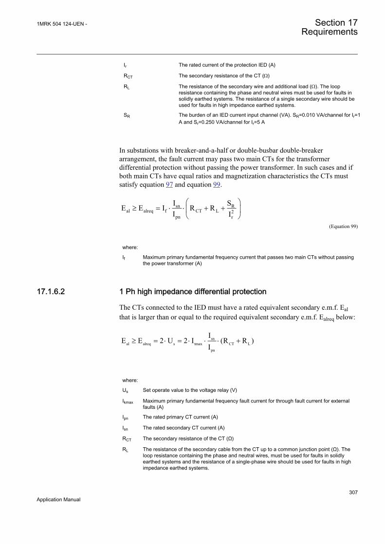
Ir The rated current of the protection IED (A)
RCT The secondary resistance of the CT (W)
RL The resistance of the secondary wire and additional load (W). The loopresistance containing the phase and neutral wires must be used for faults insolidly earthed systems. The resistance of a single secondary wire should beused for faults in high impedance earthed systems.
SR The burden of an IED current input channel (VA). SR=0.010 VA/channel for Ir=1A and Sr=0.250 VA/channel for Ir=5 A
In substations with breaker-and-a-half or double-busbar double-breakerarrangement, the fault current may pass two main CTs for the transformerdifferential protection without passing the power transformer. In such cases and ifboth main CTs have equal ratios and magnetization characteristics the CTs mustsatisfy equation 97 and equation 99.
sn Ral alreq f CT L 2
pn r
I SE E I R RI I
æ ö³ = × × + +ç ÷
è øEQUATION1414 V1 EN (Equation 99)
where:
If Maximum primary fundamental frequency current that passes two main CTs without passingthe power transformer (A)
17.1.6.2 1 Ph high impedance differential protection
The CTs connected to the IED must have a rated equivalent secondary e.m.f. Ealthat is larger than or equal to the required equivalent secondary e.m.f. Ealreq below:
snal alreq s tmax CT L
pn
IE E 2 U 2 I (R R )
I³ = × = × × × +
where:
Us Set operate value to the voltage relay (V)
Ikmax Maximum primary fundamental frequency fault current for through fault current for externalfaults (A)
Ipn The rated primary CT current (A)
Isn The rated secondary CT current (A)
RCT The secondary resistance of the CT (Ω)
RL The resistance of the secondary cable from the CT up to a common junction point (Ω). Theloop resistance containing the phase and neutral wires, must be used for faults in solidlyearthed systems and the resistance of a single-phase wire should be used for faults in highimpedance earthed systems.
1MRK 504 124-UEN - Section 17Requirements
307Application Manual
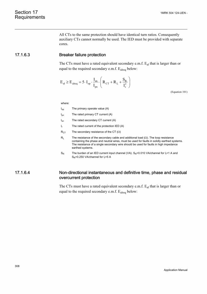
All CTs to the same protection should have identical turn ratios. Consequentlyauxiliary CTs cannot normally be used. The IED must be provided with separatecores.
17.1.6.3 Breaker failure protection
The CTs must have a rated equivalent secondary e.m.f. Eal that is larger than orequal to the required secondary e.m.f. Ealreq below:
sn Ral alreq op CT L 2
pn r
I SE E 5 I R RI I
æ ö³ = × × × + +ç ÷
è øEQUATION1380 V1 EN (Equation 101)
where:
Iop The primary operate value (A)
Ipn The rated primary CT current (A)
Isn The rated secondary CT current (A)
Ir The rated current of the protection IED (A)
RCT The secondary resistance of the CT (W)
RL The resistance of the secondary cable and additional load (W). The loop resistancecontaining the phase and neutral wires, must be used for faults in solidly earthed systems.The resistance of a single secondary wire should be used for faults in high impedanceearthed systems.
SR The burden of an IED current input channel (VA). SR=0.010 VA/channel for Ir=1 A andSR=0.250 VA/channel for Ir=5 A
17.1.6.4 Non-directional instantaneous and definitive time, phase and residualovercurrent protection
The CTs must have a rated equivalent secondary e.m.f. Eal that is larger than orequal to the required secondary e.m.f. Ealreq below:
Section 17 1MRK 504 124-UEN -Requirements
308Application Manual
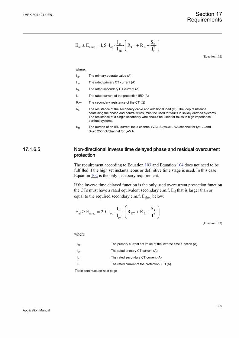
sn Ral alreq op CT L 2
pn r
I SE E 1,5 I R RI I
æ ö³ = × × × + +ç ÷
è øEQUATION1381 V1 EN (Equation 102)
where:
Iop The primary operate value (A)
Ipn The rated primary CT current (A)
Isn The rated secondary CT current (A)
Ir The rated current of the protection IED (A)
RCT The secondary resistance of the CT (W)
RL The resistance of the secondary cable and additional load (W). The loop resistancecontaining the phase and neutral wires, must be used for faults in solidly earthed systems.The resistance of a single secondary wire should be used for faults in high impedanceearthed systems.
SR The burden of an IED current input channel (VA). SR=0.010 VA/channel for Ir=1 A andSR=0.250 VA/channel for Ir=5 A
17.1.6.5 Non-directional inverse time delayed phase and residual overcurrentprotection
The requirement according to Equation 103 and Equation 104 does not need to befulfilled if the high set instantaneous or definitive time stage is used. In this caseEquation 102 is the only necessary requirement.
If the inverse time delayed function is the only used overcurrent protection functionthe CTs must have a rated equivalent secondary e.m.f. Eal that is larger than orequal to the required secondary e.m.f. Ealreq below:
sn Ral alreq op CT L 2
pn r
I SE E 20 I R RI I
æ ö³ = × × × + +ç ÷
è øEQUATION1076 V1 EN (Equation 103)
where
Iop The primary current set value of the inverse time function (A)
Ipn The rated primary CT current (A)
Isn The rated secondary CT current (A)
Ir The rated current of the protection IED (A)
Table continues on next page
1MRK 504 124-UEN - Section 17Requirements
309Application Manual
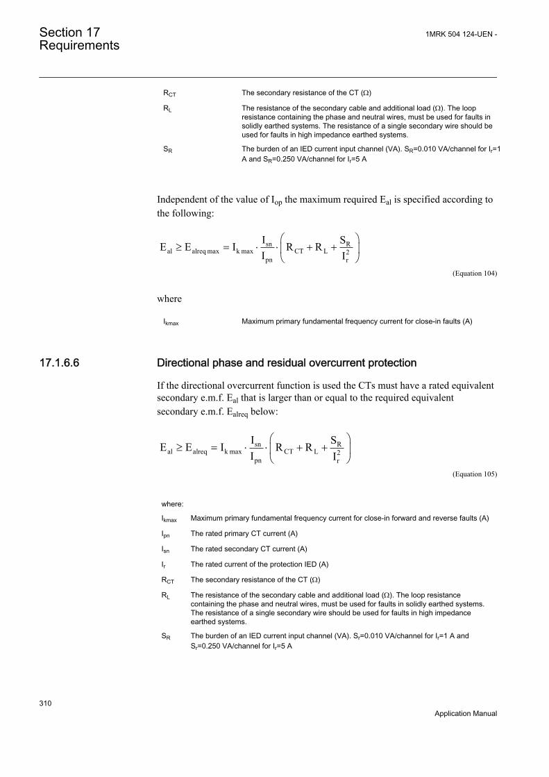
RCT The secondary resistance of the CT (W)
RL The resistance of the secondary cable and additional load (W). The loopresistance containing the phase and neutral wires, must be used for faults insolidly earthed systems. The resistance of a single secondary wire should beused for faults in high impedance earthed systems.
SR The burden of an IED current input channel (VA). SR=0.010 VA/channel for Ir=1A and SR=0.250 VA/channel for Ir=5 A
Independent of the value of Iop the maximum required Eal is specified according tothe following:
sn Ral alreq max k max CT L 2
pn r
I SE E I R RI I
æ ö³ = × × + +ç ÷
è øEQUATION1077 V1 EN (Equation 104)
where
Ikmax Maximum primary fundamental frequency current for close-in faults (A)
17.1.6.6 Directional phase and residual overcurrent protection
If the directional overcurrent function is used the CTs must have a rated equivalentsecondary e.m.f. Eal that is larger than or equal to the required equivalentsecondary e.m.f. Ealreq below:
sn Ral alreq k max CT L 2
pn r
I SE E I R RI I
æ ö³ = × × + +ç ÷
è øEQUATION1078 V1 EN (Equation 105)
where:
Ikmax Maximum primary fundamental frequency current for close-in forward and reverse faults (A)
Ipn The rated primary CT current (A)
Isn The rated secondary CT current (A)
Ir The rated current of the protection IED (A)
RCT The secondary resistance of the CT (W)
RL The resistance of the secondary cable and additional load (W). The loop resistancecontaining the phase and neutral wires, must be used for faults in solidly earthed systems.The resistance of a single secondary wire should be used for faults in high impedanceearthed systems.
SR The burden of an IED current input channel (VA). Sr=0.010 VA/channel for Ir=1 A andSr=0.250 VA/channel for Ir=5 A
Section 17 1MRK 504 124-UEN -Requirements
310Application Manual
17.1.7 Current transformer requirements for CTs according toother standardsAll kinds of conventional magnetic core CTs are possible to use with the IEDs ifthey fulfill the requirements corresponding to the above specified expressed as therated equivalent secondary e.m.f. Eal according to the IEC 60044-6 standard. Fromdifferent standards and available data for relaying applications it is possible toapproximately calculate a secondary e.m.f. of the CT comparable with Eal. Bycomparing this with the required secondary e.m.f. Ealreq it is possible to judge if theCT fulfills the requirements. The requirements according to some other standardsare specified below.
17.1.7.1 Current transformers according to IEC 60044-1, class P, PR
A CT according to IEC 60044-1 is specified by the secondary limiting e.m.f. E2max.The value of the E2max is approximately equal to the corresponding Eal accordingto IEC 60044-6. Therefore, the CTs according to class P and PR must have asecondary limiting e.m.f. E2max that fulfills the following:
2 max alreqE max imum of E>
EQUATION1383 V1 EN (Equation 106)
17.1.7.2 Current transformers according to IEC 60044-1, class PX, IEC60044-6, class TPS (and old British Standard, class X)
CTs according to these classes are specified approximately in the same way by arated knee-point e.m.f. Eknee (Ek for class PX, EkneeBS for class X and the limitingsecondary voltage Ual for TPS). The value of the Eknee is lower than thecorresponding Eal according to IEC 60044-6. It is not possible to give a generalrelation between the Eknee and the Eal but normally the Eknee is approximately 80 %of the Eal. Therefore, the CTs according to class PX, X and TPS must have a ratedknee-point e.m.f. Eknee that fulfills the following:
Eknee » Ek » EkneeBS » Ual > 0.8 · (maximum of Ealreq)EQUATION2100 V1 EN (Equation 107)
17.1.7.3 Current transformers according to ANSI/IEEE
Current transformers according to ANSI/IEEE are partly specified in differentways. A rated secondary terminal voltage UANSI is specified for a CT of class C.UANSI is the secondary terminal voltage the CT will deliver to a standard burden at20 times rated secondary current without exceeding 10 % ratio correction. Thereare a number of standardized UANSI values for example, UANSI is 400 V for a C400
1MRK 504 124-UEN - Section 17Requirements
311Application Manual

CT. A corresponding rated equivalent limiting secondary e.m.f. EalANSI can beestimated as follows:
Ea lANSI 20 Isn RCT UA NSI+× × 20 Isn RC T× × 20 Isn ZbANSI× ×+= =
EQUATION971 V1 EN (Equation 108)
where:
ZbANSI The impedance (that is, complex quantity) of the standard ANSI burden for the specific Cclass (W)
UANSI The secondary terminal voltage for the specific C class (V)
The CTs according to class C must have a calculated rated equivalent limitingsecondary e.m.f. EalANSI that fulfills the following:
alANSI alreqE max imum of E>
EQUATION1384 V1 EN (Equation 109)
A CT according to ANSI/IEEE is also specified by the knee-point voltageUkneeANSI that is graphically defined from an excitation curve. The knee-pointvoltage UkneeANSI normally has a lower value than the knee-point e.m.f. accordingto IEC and BS. UkneeANSI can approximately be estimated to 75 % of thecorresponding Eal according to IEC 60044 6. Therefore, the CTs according to ANSI/IEEE must have a knee-point voltage UkneeANSI that fulfills the following:
EkneeANSI > 0.75 · (maximum of Ealreq)EQUATION2101 V1 EN (Equation 110)
17.2 Voltage transformer requirements
The performance of a protection function will depend on the quality of themeasured input signal. Transients caused by capacitive voltage transformers(CVTs) can affect some protection functions.
Magnetic or capacitive voltage transformers can be used.
The capacitive voltage transformers (CVTs) should fulfill the requirementsaccording to the IEC 60044–5 standard regarding ferro-resonance and transients.The ferro-resonance requirements of the CVTs are specified in chapter 7.4 of thestandard.
Section 17 1MRK 504 124-UEN -Requirements
312Application Manual

The transient responses for three different standard transient response classes, T1,T2 and T3 are specified in chapter 15.5 of the standard. CVTs according to allclasses can be used.
The protection IED has effective filters for these transients, which gives secure andcorrect operation with CVTs.
1MRK 504 124-UEN - Section 17Requirements
313Application Manual

314
Section 18 Glossary
AC Alternating current
ACT Application configuration tool within PCM600
A/D converter Analog-to-digital converter
ADBS Amplitude deadband supervision
AI Analog input
ANSI American National Standards Institute
AR Autoreclosing
ASCT Auxiliary summation current transformer
ASD Adaptive signal detection
AWG American Wire Gauge standard
BI Binary input
BOS Binary outputs status
BR External bistable relay
BS British Standards
CAN Controller Area Network. ISO standard (ISO 11898) forserial communication
CB Circuit breaker
CCITT Consultative Committee for International Telegraph andTelephony. A United Nations-sponsored standards bodywithin the International Telecommunications Union.
CCVT Capacitive Coupled Voltage Transformer
Class C Protection Current Transformer class as per IEEE/ ANSI
CMPPS Combined megapulses per second
CMT Communication Management tool in PCM600
CO cycle Close-open cycle
Codirectional Way of transmitting G.703 over a balanced line. Involvestwo twisted pairs making it possible to transmit informationin both directions
COMTRADE Standard format according to IEC 60255-24
Contra-directional Way of transmitting G.703 over a balanced line. Involvesfour twisted pairs, two of which are used for transmittingdata in both directions and two for transmitting clock signals
1MRK 504 124-UEN - Section 18Glossary
315Application Manual

CPU Central processor unit
CR Carrier receive
CRC Cyclic redundancy check
CROB Control relay output block
CS Carrier send
CT Current transformer
CVT Capacitive voltage transformer
DAR Delayed autoreclosing
DARPA Defense Advanced Research Projects Agency (The USdeveloper of the TCP/IP protocol etc.)
DBDL Dead bus dead line
DBLL Dead bus live line
DC Direct current
DFC Data flow control
DFT Discrete Fourier transform
DHCP Dynamic Host Configuration Protocol
DIP-switch Small switch mounted on a printed circuit board
DI Digital input
DLLB Dead line live bus
DNP Distributed Network Protocol as per IEEE/ANSI Std.1379-2000
DR Disturbance recorder
DRAM Dynamic random access memory
DRH Disturbance report handler
DSP Digital signal processor
DTT Direct transfer trip scheme
EHV network Extra high voltage network
EIA Electronic Industries Association
EMC Electromagnetic compatibility
EMF (Electric Motive Force)
EMI Electromagnetic interference
EnFP End fault protection
EPA Enhanced performance architecture
ESD Electrostatic discharge
FCB Flow control bit; Frame count bit
Section 18 1MRK 504 124-UEN -Glossary
316Application Manual

FOX 20 Modular 20 channel telecommunication system for speech,data and protection signals
FOX 512/515 Access multiplexer
FOX 6Plus Compact time-division multiplexer for the transmission ofup to seven duplex channels of digital data over optical fibers
G.703 Electrical and functional description for digital lines used bylocal telephone companies. Can be transported overbalanced and unbalanced lines
GCM Communication interface module with carrier of GPSreceiver module
GDE Graphical display editor within PCM600
GI General interrogation command
GIS Gas-insulated switchgear
GOOSE Generic object-oriented substation event
GPS Global positioning system
HDLC protocol High-level data link control, protocol based on the HDLCstandard
HFBR connectortype
Plastic fiber connector
HMI Human-machine interface
HSAR High speed autoreclosing
HV High-voltage
HVDC High-voltage direct current
IDBS Integrating deadband supervision
IEC International Electrical Committee
IEC 60044-6 IEC Standard, Instrument transformers – Part 6:Requirements for protective current transformers fortransient performance
IEC 61850 Substation automation communication standard
IEEE Institute of Electrical and Electronics Engineers
IEEE 802.12 A network technology standard that provides 100 Mbits/s ontwisted-pair or optical fiber cable
IEEE P1386.1 PCI Mezzanine Card (PMC) standard for local bus modules.References the CMC (IEEE P1386, also known as CommonMezzanine Card) standard for the mechanics and the PCIspecifications from the PCI SIG (Special Interest Group) forthe electrical EMF (Electromotive force).
IED Intelligent electronic device
1MRK 504 124-UEN - Section 18Glossary
317Application Manual
I-GIS Intelligent gas-insulated switchgear
Instance When several occurrences of the same function are availablein the IED, they are referred to as instances of that function.One instance of a function is identical to another of the samekind but has a different number in the IED user interfaces.The word "instance" is sometimes defined as an item ofinformation that is representative of a type. In the same wayan instance of a function in the IED is representative of atype of function.
IP 1. Internet protocol. The network layer for the TCP/IPprotocol suite widely used on Ethernet networks. IP is aconnectionless, best-effort packet-switching protocol. Itprovides packet routing, fragmentation and reassemblythrough the data link layer.2. Ingression protection, according to IEC standard
IP 20 Ingression protection, according to IEC standard, level 20
IP 40 Ingression protection, according to IEC standard, level 40
IP 54 Ingression protection, according to IEC standard, level 54
IRF Internal failure signal
IRIG-B: InterRange Instrumentation Group Time code format B,standard 200
ITU International Telecommunications Union
LAN Local area network
LIB 520 High-voltage software module
LCD Liquid crystal display
LDD Local detection device
LED Light-emitting diode
MCB Miniature circuit breaker
MCM Mezzanine carrier module
MVB Multifunction vehicle bus. Standardized serial bus originallydeveloped for use in trains.
NCC National Control Centre
OCO cycle Open-close-open cycle
OCP Overcurrent protection
OLTC On-load tap changer
OV Over-voltage
Overreach A term used to describe how the relay behaves during a faultcondition. For example, a distance relay is overreachingwhen the impedance presented to it is smaller than the
Section 18 1MRK 504 124-UEN -Glossary
318Application Manual

apparent impedance to the fault applied to the balance point,that is, the set reach. The relay “sees” the fault but perhaps itshould not have seen it.
PCI Peripheral component interconnect, a local data bus
PCM Pulse code modulation
PCM600 Protection and control IED manager
PC-MIP Mezzanine card standard
PISA Process interface for sensors & actuators
PMC PCI Mezzanine card
POR Permissive overreach
POTT Permissive overreach transfer trip
Process bus Bus or LAN used at the process level, that is, in nearproximity to the measured and/or controlled components
PSM Power supply module
PST Parameter setting tool within PCM600
PT ratio Potential transformer or voltage transformer ratio
PUTT Permissive underreach transfer trip
RASC Synchrocheck relay, COMBIFLEX
RCA Relay characteristic angle
RFPP Resistance for phase-to-phase faults
RFPE Resistance for phase-to-earth faults
RISC Reduced instruction set computer
RMS value Root mean square value
RS422 A balanced serial interface for the transmission of digitaldata in point-to-point connections
RS485 Serial link according to EIA standard RS485
RTC Real-time clock
RTU Remote terminal unit
SA Substation Automation
SBO Select-before-operate
SC Switch or push button to close
SCS Station control system
SCADA Supervision, control and data acquisition
SCT System configuration tool according to standard IEC 61850
SDU Service data unit
1MRK 504 124-UEN - Section 18Glossary
319Application Manual
SMA connector Subminiature version A, A threaded connector with constantimpedance.
SMT Signal matrix tool within PCM600
SMS Station monitoring system
SNTP Simple network time protocol – is used to synchronizecomputer clocks on local area networks. This reduces therequirement to have accurate hardware clocks in everyembedded system in a network. Each embedded node caninstead synchronize with a remote clock, providing therequired accuracy.
SRY Switch for CB ready condition
ST Switch or push button to trip
Starpoint Neutral point of transformer or generator
SVC Static VAr compensation
TC Trip coil
TCS Trip circuit supervision
TCP Transmission control protocol. The most common transportlayer protocol used on Ethernet and the Internet.
TCP/IP Transmission control protocol over Internet Protocol. The defacto standard Ethernet protocols incorporated into 4.2BSDUnix. TCP/IP was developed by DARPA for Internetworking and encompasses both network layer and transportlayer protocols. While TCP and IP specify two protocols atspecific protocol layers, TCP/IP is often used to refer to theentire US Department of Defense protocol suite based uponthese, including Telnet, FTP, UDP and RDP.
TNC connector Threaded Neill-Concelman, a threaded constant impedanceversion of a BNC connector
TPZ, TPY, TPX,TPS
Current transformer class according to IEC
UMT User management tool
Underreach A term used to describe how the relay behaves during a faultcondition. For example, a distance relay is underreachingwhen the impedance presented to it is greater than theapparent impedance to the fault applied to the balance point,that is, the set reach. The relay does not “see” the fault butperhaps it should have seen it. See also Overreach.
U/I-PISA Process interface components that deliver measured voltageand current values
UTC Coordinated Universal Time. A coordinated time scale,maintained by the Bureau International des Poids et Mesures(BIPM), which forms the basis of a coordinated
Section 18 1MRK 504 124-UEN -Glossary
320Application Manual

dissemination of standard frequencies and time signals. UTCis derived from International Atomic Time (TAI) by theaddition of a whole number of "leap seconds" to synchronizeit with Universal Time 1 (UT1), thus allowing for theeccentricity of the Earth's orbit, the rotational axis tilt (23.5degrees), but still showing the Earth's irregular rotation, onwhich UT1 is based. The Coordinated Universal Time isexpressed using a 24-hour clock, and uses the Gregoriancalendar. It is used for aeroplane and ship navigation, whereit is also sometimes known by the military name, "Zulutime." "Zulu" in the phonetic alphabet stands for "Z", whichstands for longitude zero.
UV Undervoltage
WEI Weak end infeed logic
VT Voltage transformer
X.21 A digital signalling interface primarily used for telecomequipment
3IO Three times zero-sequence current. Often referred to as theresidual or the earth-fault current
3UO Three times the zero sequence voltage. Often referred to asthe residual voltage or the neutral point voltage
1MRK 504 124-UEN - Section 18Glossary
321Application Manual

322

323

Contact us
ABB ABSubstation Automation ProductsSE-721 59 Västerås, SwedenPhone +46 (0) 21 32 50 00Fax +46 (0) 21 14 69 18
www.abb.com/substationautomation
1MR
K 5
04 1
24-U
EN
-©
Cop
yrig
ht 2
011
AB
B. A
ll rig
hts
rese
rved
.