TRANSFORMER OIL MAINTENANCE - SASTA · TRANSFORMER OIL MAINTENANCE ... and allows the maintenance...
7
REFEREED PAPER TRANSFORMER OIL MAINTENANCE SKINNER BA 1 Montgomery Road, Mount Edgecombe, 4300, South Africa [email protected] Abstract In electrical distribution, the transformer is the workhorse of the industry. The majority of transformers are oil filled, air cooled units which are frequently neglected after installation. However, even a poorly maintained transformer may perform adequately for many years without incident. Water retention resulting in corrosion is the major cause of failure in transformers that have passed the initial high failure time zone. The secondary effects of corrosion, acid formation, and the degeneration of the insulation material can lead to failures under short term stress conditions while the protection clears the fault. Traditional drying methods take long periods of time and involve heating, hot oil sprays and vacuum techniques, and will result in only partial compliance. The majority of the water will reside in the insulation and over time will migrate back into the oil. The moisture will return to unacceptable levels, lowering the insulation levels and attacking the internal parts. Only the removal of the transformer and drying it out over a number of days in a large oven over several cycles will guarantee a positive result. The cost of installing a standby unit and the accompanying loss of revenue may be prohibitive. The method of preventing transformer failure described in this paper utilises low energy and standard equipment, and allows the maintenance work to be completed on site over a comparatively short period of time. The documented results prove that there is an alternative method of drying the oil and extending the life of the transformer. Keywords: transformer, low frequency heating, variable speed drive, VSD, VpCI Introduction The traditional method of drying a faulty transformer will remove moisture from the oil but not from the core. Removing the oil from the core requires that the transformer be emptied and heated in a very large oven over several cycles, which will incur a high energy bill with the risk of damage during transport to the oven. The on site use of a variable speed drive (VSD) with low voltage and frequency affords internal heating to drive the moisture from the core quickly and safely at low cost and with limited risks. Additions to the ‘breather’ to prevent corrosion in the vapour space of the conservator will increase the life of the transformer and prevent early failure. Basics of transformer design Transformers are used to change electrical voltage to the level where it can be used, e.g. up for transmission and down for use in factories and machines. There are no moving parts in Skinner BA Proc S Afr Sug Technol Ass (2013) 86: 464 - 470 464
Transcript of TRANSFORMER OIL MAINTENANCE - SASTA · TRANSFORMER OIL MAINTENANCE ... and allows the maintenance...

REFEREED PAPER
TRANSFORMER OIL MAINTENANCE
SKINNER BA
1 Montgomery Road, Mount Edgecombe, 4300, South Africa
Abstract
In electrical distribution, the transformer is the workhorse of the industry. The majority of
transformers are oil filled, air cooled units which are frequently neglected after installation.
However, even a poorly maintained transformer may perform adequately for many years
without incident. Water retention resulting in corrosion is the major cause of failure in
transformers that have passed the initial high failure time zone. The secondary effects of
corrosion, acid formation, and the degeneration of the insulation material can lead to failures
under short term stress conditions while the protection clears the fault. Traditional drying
methods take long periods of time and involve heating, hot oil sprays and vacuum techniques,
and will result in only partial compliance. The majority of the water will reside in the
insulation and over time will migrate back into the oil. The moisture will return to
unacceptable levels, lowering the insulation levels and attacking the internal parts. Only the
removal of the transformer and drying it out over a number of days in a large oven over
several cycles will guarantee a positive result. The cost of installing a standby unit and the
accompanying loss of revenue may be prohibitive.
The method of preventing transformer failure described in this paper utilises low energy and
standard equipment, and allows the maintenance work to be completed on site over a
comparatively short period of time. The documented results prove that there is an alternative
method of drying the oil and extending the life of the transformer.
Keywords: transformer, low frequency heating, variable speed drive, VSD, VpCI
Introduction
The traditional method of drying a faulty transformer will remove moisture from the oil but
not from the core. Removing the oil from the core requires that the transformer be emptied
and heated in a very large oven over several cycles, which will incur a high energy bill with
the risk of damage during transport to the oven. The on site use of a variable speed drive
(VSD) with low voltage and frequency affords internal heating to drive the moisture from the
core quickly and safely at low cost and with limited risks. Additions to the ‘breather’ to
prevent corrosion in the vapour space of the conservator will increase the life of the
transformer and prevent early failure.
Basics of transformer design
Transformers are used to change electrical voltage to the level where it can be used, e.g. up
for transmission and down for use in factories and machines. There are no moving parts in
Skinner BA Proc S Afr Sug Technol Ass (2013) 86: 464 - 470
464
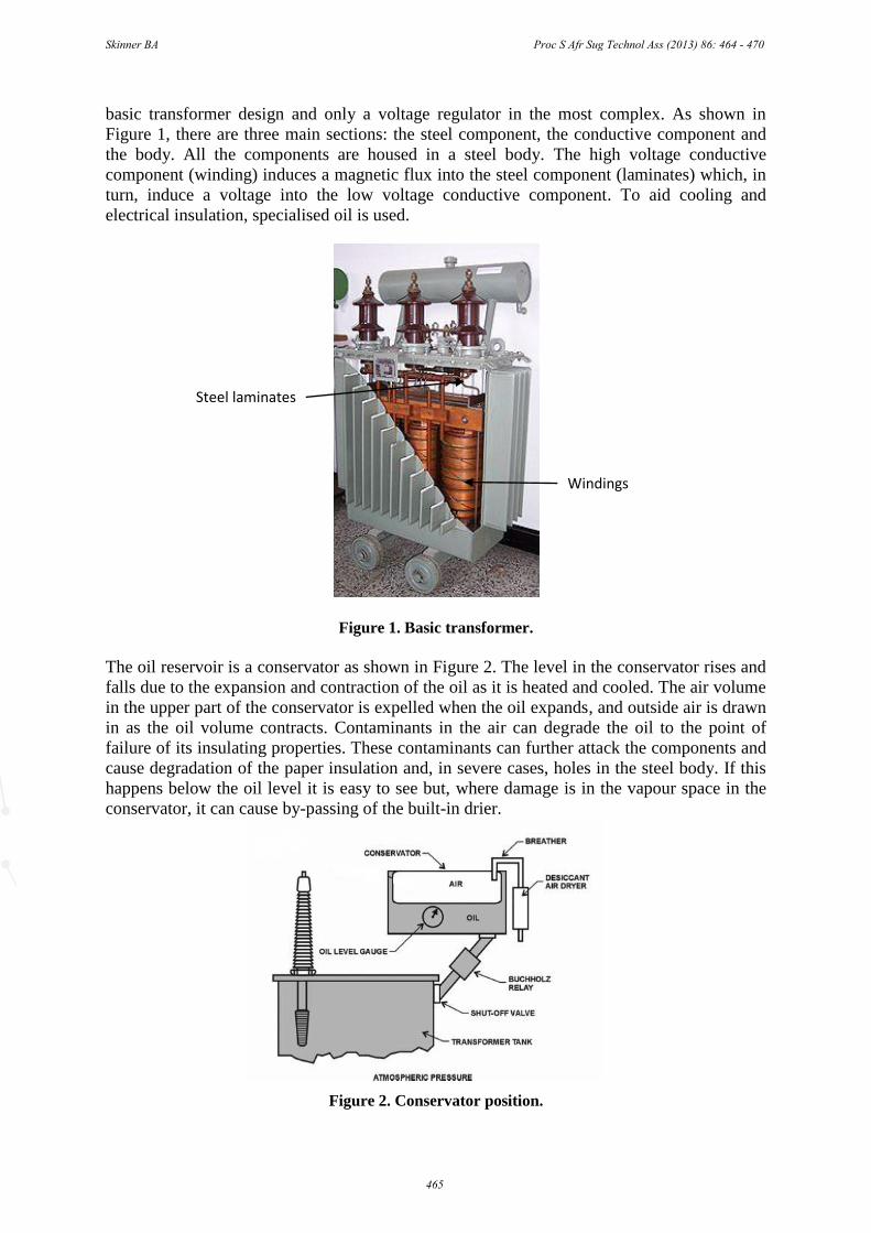
basic transformer design and only a voltage regulator in the most complex. As shown in
Figure 1, there are three main sections: the steel component, the conductive component and
the body. All the components are housed in a steel body. The high voltage conductive
component (winding) induces a magnetic flux into the steel component (laminates) which, in
turn, induce a voltage into the low voltage conductive component. To aid cooling and
electrical insulation, specialised oil is used.
Figure 1. Basic transformer.
The oil reservoir is a conservator as shown in Figure 2. The level in the conservator rises and
falls due to the expansion and contraction of the oil as it is heated and cooled. The air volume
in the upper part of the conservator is expelled when the oil expands, and outside air is drawn
in as the oil volume contracts. Contaminants in the air can degrade the oil to the point of
failure of its insulating properties. These contaminants can further attack the components and
cause degradation of the paper insulation and, in severe cases, holes in the steel body. If this
happens below the oil level it is easy to see but, where damage is in the vapour space in the
conservator, it can cause by-passing of the built-in drier.
Figure 2. Conservator position.
Body
Windings
Steel laminates
Windings
Skinner BA Proc S Afr Sug Technol Ass (2013) 86: 464 - 470
465

To prevent moisture and contamination from microscopic particles, an air dryer or ‘breather’
is used. The breather consists of an oil trap and a silica gel drier. The oil trap prevents direct
contact of the air with the silica gel until it is drawn in, and also traps particles. At the top of
the breather there is a sponge which should prevent particles of the silica being drawn into the
oil circuit.
Maintenance
Moisture is the main cause of transformer failure. Keeping the oil dry and free of
contaminants is critical. There are only a few tests that need to be done on a regular basis if
there has been no incident to cause concern. These relate to simple electrical resistance and
insulation checks, and oil testing for dielectric strength and moisture content. More precise
tests can include tan delta, surface tension and direct gas analysis (Grey, 2006).
Correction of the hydrated oil
There is a standard method of dehydration and purification that uses a machine to suck the oil
from the bottom of the transformer main tank, heat it, then spray it into a chamber under a
slight vacuum and centrifuge the solids out. It is then pumped back into the transformer via
the conservator. Low vacuum cannot be used due to the lowering of the breakdown voltage at
lower pressures (Paschen law). Flow rates have to be controlled, and there is a limit to the
flow rate due to a possible washing effect on the paper insulation. There are pockets of low
temperature due to channelling, and the oil has to be heated with a low density heater to
prevent it from cracking. A 1500 L transformer can take as long as two hours to heat up to
80°C, even when it has been on load just prior to the start of the procedure. Removal of
40 ppm of water will take another four hours. Taking the oil from 50 to 10 ppm is relatively
easy; however, to get to 5 ppm could take another six hours, thus the recommended cut-off
point is 8-10 ppm.
Within two weeks the oil hydration can return to 50 ppm if the core is saturated, as the water
diffuses from the paper into the oil. The entire process will then have to be repeated. There is
a method of calculating the amount of moisture in the paper. A 3-MVA unit can contain 5 L
of water, and a 300-MVA transformer can contain 300 L of water. Removing the water at
40 mL per session is a time consuming task and the transformer may fail before the process is
complete.
The introduction of internal heating of the core while the drying process is taking place
(Figure 3) keeps the moisture differential high and facilitates the removal of the moisture at
an optimum (Koestinger et al., 2004). This can be seen in Figure 4, where the VSD is turned
on and the moisture level in the oil rises. To heat the core, the low voltage side is shorted out
with conductors rated at the full load current. A modified electronic variable speed
(frequency) drive is used on the high voltage side to deliver the rated current at a low voltage
(Ward, 2006). This low voltage is achieved by the use of a low frequency, causing the
impedance to be low. Impedance is calculated from 2πfL where L is the inductance and f is
the frequency. The inductance is proportional to the frequency and thus, the lower the
frequency, the lower the impedance and the higher the current that can be delivered at lower
voltages for the same energy level. Direct current cannot be used as there would not be any
energy transfer to the low voltage side. All the transformer safety devices are wired into the
drive to trip in the event of a failure. Care should be taken not to drive the oil moisture over
the 80 ppm level, or there will be the danger of boiling the free water and possible damage to
Skinner BA Proc S Afr Sug Technol Ass (2013) 86: 464 - 470
466
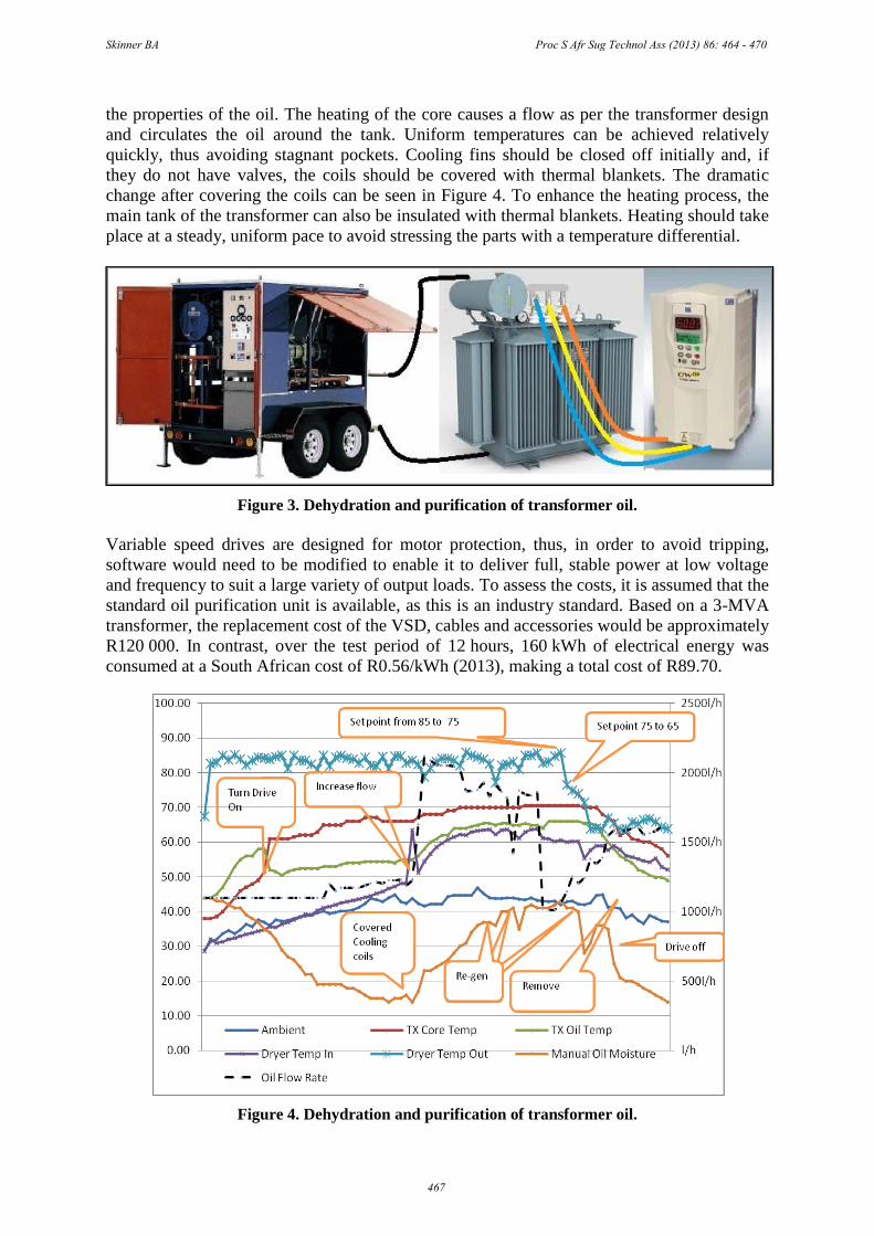
the properties of the oil. The heating of the core causes a flow as per the transformer design
and circulates the oil around the tank. Uniform temperatures can be achieved relatively
quickly, thus avoiding stagnant pockets. Cooling fins should be closed off initially and, if
they do not have valves, the coils should be covered with thermal blankets. The dramatic
change after covering the coils can be seen in Figure 4. To enhance the heating process, the
main tank of the transformer can also be insulated with thermal blankets. Heating should take
place at a steady, uniform pace to avoid stressing the parts with a temperature differential.
Figure 3. Dehydration and purification of transformer oil.
Variable speed drives are designed for motor protection, thus, in order to avoid tripping,
software would need to be modified to enable it to deliver full, stable power at low voltage
and frequency to suit a large variety of output loads. To assess the costs, it is assumed that the
standard oil purification unit is available, as this is an industry standard. Based on a 3-MVA
transformer, the replacement cost of the VSD, cables and accessories would be approximately
R120 000. In contrast, over the test period of 12 hours, 160 kWh of electrical energy was
consumed at a South African cost of R0.56/kWh (2013), making a total cost of R89.70.
Figure 4. Dehydration and purification of transformer oil.
Skinner BA Proc S Afr Sug Technol Ass (2013) 86: 464 - 470
467

Prophylactic solutions
It is recommended that, for transformers up to 3-MVA, a size 4 silica breather be used in all
cases. For larger transformers, double the manufacturer’s suggested selection of breather size.
Low maintenance will no longer be a problem as, even where some scheduled maintenance
routines are missed, the large quantity of silica gel will extend the life of the transformer. A
long, thin breather unit should be selected to enable greater dwell time over the product
without channelling.
Use of vapour phase corrosion inhibitors
In extreme cases of moisture ingress, pinholes form in the conservator vapour space. Once
this happens, the breather becomes useless. This can be seen when the silica gel in the
breather becomes discoloured at the top, on the conservator side.
Vapour phase corrosion inhibitors (VpCIs) were first introduced around the end of World
War I. These corrosion inhibitors can exist as individual components, or as combinations to
perform functions over different vapour pressures. VpCIs are organic chemicals comprised of
carbonic amine salts. These salts vaporise under normal atmospheric conditions and condense
on all metal surfaces, including recesses and cavities. They work by passivating the corrosion
cells on metal surfaces and thus provides both anodic and cathodic protection (Mathew,
2010).
As shown in Figure 5, the vapour separates into ions which dissolve into an electrolyte along
with the moisture and become attached to the metal in a single monomolecular layer. This
layer is self-healing and self-relishing from the amine salt reservoir.
Figure 5. Vapour phase corrosion inhibitors.
These amine salts can be infused into water, paper, oil, waxes, cardboard and plastic films,
and can also be put into sprays and gases, or just left in the crystalline form. Because of this
flexibility the amine salts can be delivered in a fog or injection, they can migrate, and they
can be applied with a brush, dipped, sprayed and wrapped.
A trial was run by taking two 200 L drums and fitting one with a standard breather and the
other with a modified breather. Figure 6 shows a modified breather (van der Merwe, 2012) to
which a small top section has been added and a VpCI inserted. This addition allows the
vapour space of the conservator to be filled with carboxylate amine salts (Mathew, 2010)
Skinner BA Proc S Afr Sug Technol Ass (2013) 86: 464 - 470
468

which vaporise under normal atmospheric conditions and condense on all metal surfaces,
including recessed areas and cavities. It then passivates the corrosion cells on all metal
surfaces by providing anodic and cathodic protection at a mono-molecular level. Failure of
the conservator due to internal rusting and bypassing of the silica gel breather is now
prevented.
Figure 6. Modified breather.
In August, a mild steel rod was inserted into each drum as a removable test piece. After three
months the rods were examined and found to be in good condition, proving that the silica gel
had prevented moisture from getting into the drums and had protected the vapour space.
The silica gel was then removed from the standard breather, leaving the modified breather
with two sachets of gel in the upper section. The drums were left outside from October to
January. Again the rods were removed. As can be seen from Figure 7, the rod from the drum
with the standard breather and no gel was heavily corroded. The rod from the drum with the
modified breather and a small amount of gel had no rust. This showed that the silica gel will
prevent moisture from getting into the conservator and that, even where moisture is present in
the drum, the VpCI will prevent rust from forming.
Figure 7. Mild steel rods used as test pieces.
Checked rod
drum no. 1, found
rod badly rusted.
Checked rod
drum no. 2,
found no rust.
Skinner BA Proc S Afr Sug Technol Ass (2013) 86: 464 - 470
469

Conclusion
The alternative method of low frequency heating utilising variable speed drives to assist in
the removal of water from conventional power transformers can be carried out effectively.
The method is fast, safe and cost effective, and will not damage the unit. Use of larger
breathers and the addition of vapour phase corrosion inhibitors will enable the integrity of the
conservator to be maintained for extended periods of time and under adverse conditions.
REFERENCES
Grey I (2006).Transformer Chemistry Services. Testing of oil samples and setting standards. IEC
60422.
Koestinger P, Aronsen E, Boss P and Rindlisbacher G (2004). Practical experience with the drying of
power transformers in the field, applying the LFH technology. Cigré A2-205 of 2004.
Mathew PK (2010). Corrosion protection during storage and transit using vapour phase corrosion
inhibitors. Cortec, India.
van der Merwe L (2012). Global Transformer Services. Drying equipment and modifications of the
new dryer.
Ward G (2006). CFW11 drive. Drive and modification of the software. Zest WEG Group, Durban,
South Africa.
Skinner BA Proc S Afr Sug Technol Ass (2013) 86: 464 - 470
470