Training Report on Barauni Thermal Power Station
43
1 BIHAR STATE POWER GENERATION CO. LTD BARAUNI THERMAL POWER STATION BEGUSARAI, BIHAR A TRAINING REPORT SUBMITTED IN PARTIAL FULFILLMENT OF THE REQUIREMENTS FOR THE AWARD OF THE DEGREE OF BACHELOR OF TECHNOLOGY (ELECTRICAL & ELECTRONICS ENGUNEERING) SUBMITTED TO BRCM COLLEGE OF ENGINEERING & TECHNOLOGY BAHAL-127028 SUBMITTED BY Name Of Student College Roll No. Gulshan Kumar Nirala 12-EEE-1112 (02 JULY 2014 – 31 JULY 2014) BRCM COLLEGE OF ENGINEERING & TECHNOLOGY
-
Upload
gulshan-singh -
Category
Engineering
-
view
817 -
download
6
Transcript of Training Report on Barauni Thermal Power Station

1
BIHAR STATE POWER GENERATION CO. LTD
BARAUNI THERMAL POWER STATION
BEGUSARAI, BIHAR
A TRAINING REPORT
SUBMITTED IN PARTIAL FULFILLMENT OF THE REQUIREMENTS FOR THE
AWARD OF THE DEGREE OF
BACHELOR OF TECHNOLOGY (ELECTRICAL & ELECTRONICS ENGUNEERING)
SUBMITTED TO
BRCM COLLEGE OF ENGINEERING & TECHNOLOGY
BAHAL-127028
SUBMITTED BY Name Of Student College Roll No.
Gulshan Kumar Nirala 12-EEE-1112
(02 JULY 2014 – 31 JULY 2014)
BRCM COLLEGE OF ENGINEERING & TECHNOLOGY

2
PREFACE
A student gets theoretical knowledge from classroom and gets practical knowledge from
industrial training. When these two aspects of theoretical knowledge and practical experience
together then a student is full equipped to secure his best.
In conducting the project study in an industry, students get exposed and have
knowledge of real situation in the work field and gains experience from them. The object of the
summer training cum project is to provide an opportunity to experience the practical aspect of
Technology in any organization. It provides a chance to get the feel of the organization and its
function.
The fact that thermal energy is the major source of power generation itself shows the
importance of thermal power generation in India – more than 60 percent of electric power is
produced by steam plant in India.
In steam power plants, the heat of combustion of fossil fuels is utilized by the boilers
to raise steam at high pressure and temperature. The steam so produced is used in driving
the steam turbine coupled to generators and thus in generating ELECTRICAL ENERGY

3
ACKNOWLEDGEMENT
It is a matter of great pleasure and privilege for me to present this report of 30 days
on the basis of practical knowledge gained by me during practical training at BARAUNI
THERMAL POWER STATION (B.T.P.S.), BEGUSARAI (Bihar) during session 2013-2014.
I with full pleasure converge my heartiest thanks to Head of Electrical Department,
Mr. Dheeraj Kumar,BRCM COLLEGE OF ENGINEERING & TECHNOLOGY and to my guide
Mr. Vikrant Verma, Assistant Professor, Department of Electrical & Electronics Engineering.
Gulshan Kumar Nirala

4
FIGURE LIST
Figure Page No
Figure 1.1 VIEW OF BARAUNI THERMAL POWER PLANT 11
Figure 2.1 LAYOUT OF POWER PLANT 12
Figure 2.2 CROSS SECTIONAL VIEW OF FOUR MAJOR PART 14
Figure 3.1 WAGON TRIPLER 16
Figure 4.1 CROSS SECTIONAL VIEW OF ASH HANDLING PLANT 19 Figure 6.1 CROSS SECTIONAL VIEW OF FURNANCE 22
Figure 6.2 PULVERISED SYSTEM 23
Figure 6.3 CROSS SECTIONAL VIEW OF STEAM DRUM 24
Figure 6.4 ECONOMIZER 25
Figure 6.5 AIR PRE-HEATER 26 Figure 7.1 STEAM TURBINE 30
Figure 8.1 CROSS SECTIONAL VIEW OF TURBO GENERATOR 39
Figure 9.1 HYDROGEN COOLED ALTERNATOR 41
Figure 10.1 CROSS SECTIONAL VIEW OF CONTROL ROOM 43

5
CONTENTS
Title Page No
CHAPTER 1 INTRODUCTION…………………………..…………. 08-11
1.1 DESIGN OF B.T.P.S. ……………………..... ……………….. 9
1.2 SITE SELECTION CRITERIA………………….. ……………… 10
1.3 DESIGN FEATURES………………………....... ………………. 10 CHAPTER 2 GENERAL LAYOUT AND BASIC IDEA…………….. 12-14
2.1 FUEL AND ASH CIRCUIT………………………………………… 12
2.2 AIR AND GAS CIRCUIT…………………………………………... 13
2.3 FEED WATER AND STEAM CIRCUIT………………………….. 13
2.4 COOLING WATER CIRCUIT…………….................................... 13 CHAPTER 3 COAL HANDLING PLANT……………………………. 15-17
3.1 WAGON UNLOADING SYSTEM………………………………… 15
3.2 CRUSHING SYSTEM……………………………………………... 16
3.3 CONSTRUCTION AND OPERATION…………………………… 17 3.4 CONVEYING SYSTEM……………………………………………. 17
3.5 CONVEYOR BELT SPECIFICATION…………………………… 17
CHAPTER 4 ASH HANDLING PLANT…………………………......... 18-19
4.1 FUEL AND ASH PLANT………………………….. ……………… 18
4.2 AIR AND GAS PLANT…………………………………………….. 18 4.3 ASH AND DUST COLLECTION PLANT………………………… 18
4.4 UTILISATION……………………………………………………….. 19

6
CHAPTER 5 ELECTRO-STATIC PRECIPITATOR…………………. 20
5.1 PRINCIPLE OF OPERATION……………………………………. 20
5.2 CONTROLLER…………………………………………………….. 20 5.3 HIGH VOLTAGE RECTIFIER TRANSFORMER……………… 20
5.4 E.S.P. FIELD……………………………………........................... 20
CHAPTER 6 BOILER…………………………………………………….. 21-29
6.1 BOILER CLASSIFICATION……………………………………… 21
6.2 FURNANCE………………………………………………………. 22 6.3 PULVERISED FUEL SYSTEM…………………………………. 22
6.4 FUEL OIL SYSTEM………………………………………………. 23
6.5 BOILER DRUM…………………………………………………… 23
6.6 DRAFT SYSTEM…………………………….. …………………. 24
6.7 DRAUGHT FAN………………………………. ……………….... 25 6.8 ECONOMIZER………………………………. ………………….. 25
6.9 AIR-PREHEATER……………………………. …………………. 26
6.10 SUPERHEATER………………………………………………… 27
6.11 REHEATER……………………………………………………… 27
6.12 CIRCULATION SYSYTEM………………................................. 27 6.13 SOOT BLOWER…………………………………………………. 28
6.14 TECHNICAL SPECIFICATION OF BOILER........................... 28
CHAPTER 7 STEAM TURBINE………………………………………… 30-32
7.1 PRINCIPLE …………………………………………………………. 31
7.2 DESCRIPTION OF STEAM TURBINE…………………………… 31
7
CHAPTER 8 TURBO GENERATOR……………………………………. 33-39
8.1 THEORY……………………………………………………………. 33
8.2 ROTOR……………………………………………………………… 36 CHAPTER 9 COOLING SYSTEM……………………………………… .. 40-41
9.1 INTRODUCTION…………………………………………………... 40
9.2 HYDROGEN DRYER……………………………………………… 40
CHAPTER 10 CONTROL ROOM………………………………………… 42-43
10.1 MAIN CONTROL ROOM……………………………………….. 42
10.2 CONTROL PANEL I…………………………………………….. 42
10.3 CONTROL PANEL II……………………………………………. 42 10.4 CONTROL PANEL III……………………………………………. 43
10.5 CONTROL PANEL IV……………………………………………. 43
10.6 CONTROL PANEL V……………………………………………. 43

8
CHAPTER -1
INTRODUCTION
The expansion of BTPS (2x250 MW) has been sanctioned by State Govt. under State Plan at a total project Cost is Rs. 3666 Crores. The work is being done by M/s BHEL on turn-key basis and project activity consultant is M/s STEAG. Ganga water scheme is under progress for BTPS Extension at an estimated cost of Rs. 173.00 Crores. The state government made a strong plea for the allocation of coal linkage for the expansion project of Barauni Thermal Power Station (BTPS) in Begusarai district. "Bihar needs at least two coal blocs," state Energy minister Bijendra Prasad Yadav told the Planning Commission at its meeting in New Delhi on Tuesday to discuss and review of the energy scenario in the country. "After obtaining all the necessary clearance, Barauni's (250x 2 MW) expansion project is pending for want of coal linkage. The Japan International Corporation Agency has already given clearance for its financial assistance but it would be done only after we get coal linkage," the minister said. 2. Key Points of this Scheme: • Under BSEB (Bihar State electricity Board). • 2 x 250 MW Extension at Barauni TPS. • DPR prepared by M/s DCPL, Kolkata, Estimated Cost- Rs. 3066 Crores based at prices in Jan-Mar 2009 excluding cost of Land. • Additional Land requirement- 615.37 acres. Present estimated cost Rs. 67.05 Crores . Rs. 38.54 Crores has been deposited with concerned DM for acquisition of about 355 acres. • MoP has recommended MoC in August 2010 for allocation of Coal for 12th Plan. • Coal requirement - 2.65MMTPA. Processing fee of Rs. 5.00 lakh submitted to Ministry of Coal by BSEB vide letter no. 682 dated 27.06.06 for coal linkage. still Probable Coal linkage from Rajmahal coal field or Urma Pahari Tola. Firm Coal linkage awaited. • BHEL to implement BTG package (Boiler-Turbine-Generator) as OEM (Original Equipment Manufacturer). Techno-commercial offer will be submitted by BHEL

9
shortly. • BPIC - JV of GoB, BSEB & ILFS is BSEB’s consultant for carrying out Pre award project development activity for setting up 2 x 250 MW Extension project at BTPS. • State Plan outlay amounting to Rs. 180 Crores has been released in the FY 2009-10. • M/s DESEIN appointed as Technical consultant for preparation of technical Specifications of BOP Package. Appointment of single BOP EPC Packages by M/s Desein though bidding process is in progress. M/s BARSYL appointed as Technical consultant for development of Rail infrastructure at BTPS. • Water requirement for consumptive use to be met from river Ganga. Water Resources Dept., Government of Bihar has accorded clearance for 60 Cusecs for BTPS units (Existing & Extension units) and approval from CWC is accorded for 45 Cusec. • Ganga Water Scheme: M/S WAPCOS is consultant for preparation of DPR. Draft DPR submitted. Final DPR could not be submitted by M/s WAPCOS as clearance from Railway is yet to be obtained. • Expected schedule of Commissioning - 1st Unit synchronization in June ‘2014, 2nd Unit after 4 months of synchronization of 1st Unit. A provision of Rs 100.00 Crores has been made for BTPS extension along with Ganga water scheme under Annual Plan 2012-13.
1.1 B.T.P.S. IS DESISIGNED IN FOLLOWING STAGES:-
Unit Installed Capacity (MW) Date of Commissioning
1 15 1977 May
2 15 1978 August
3 15 2012 February
4 50 2013 October
5 50 2013 October
6 110 2013 October
7 110 2013 October
8 250 2014
9 250 2014
Total Power Generation – 865 MW
10
1.2 SITE SELECTION CRITERIA 1.2.1 LOCATION:- The Barauni Thermal Power Station is ideally on the left bank of Ganga River. Its about 100 km from @[110690335625299:Patna, India]. 5 km from Hathidah junction, about 12 km from Barauni junction and 8 km from Begusarai railway station. So one can easily reach the place from any part of Bihar.
1.2.2 LAND:- Land measuring approx. 250 hectares was required for the project in 1976, For disposal of ash tank very near to power station is acquired which the ash in slurry
form is disposed off through ash and slurry disposal plants.
1.2.3 COAL:- Coal requirement - 2.65MMTPA. Processing fee of Rs. 5.00 lakh submitted to Ministry of Coal by BSEB vide letter no. 682 dated 27.06.06 for coal linkage. still Probable Coal linkage from Rajmahal coal field or Urma Pahari Tola. Firm Coal linkage awaited. 1.3 DESIGN FEATURES:- The satisfactory design consists of the flowing steps.
Estimation of cost.
Selection of site.
Capacity of Power Station.
Selection of Boiler & Turbine.
Selection of Condensing Unit.
Selection of Electrical Generator.
Selection of Cooling System.
Design of Control and instrumentation system.
The design of steam power station requires wide experience as the subsequent
operation and maintenance are greatly affected by its design. The most efficient design consist of properly sized component designed to operate safely and conveniently along with its auxiliaries and installation.

11
Figure 1.1 VIEW OF KOTA SUPER THERMAL POWER PLANT

12
CHAPTER -2
General Layout & Basic Idea
A control system of station basically works on Rankin Cycle. Steam is produced in
Boiler is exported in prime mover and is condensed in condenser to be fed into the boiler again. In practice of good number of modifications are affected so as to have heat economy and to increase the thermal efficiency of plant.
Figure 2.1 Layout of Power Plant
The Kota Thermal Power Station is divided into four main circuits : Fuel and Ash Circuit.
Air and Gas Circuit. Feed water and Steam Circuit.
Cooling Water Circuit.
2.1 Fuel & Ash Circuit:- Fuel from the storage is fed to the boiler through fuel handling device. The fuel used in
KSTPS is coal, which on combustion in the boiler produced the ash. The quantity of ash produced is approximately 35-40% of coal used. This ash is collected at the back of the boiler and removed to ash storage tank through ash disposal equipment.

13
2.2 Air and Gas Circuit:- Air from the atmosphere is supplied to the combustion chamber of Boiler through the action of forced draft fan and induced draft fan. The flue gas gases are first pass around
the boiler tubes and super heated tubes in the furnace, next through dust collector (ESP) & then economizer. Finally, they are exhausted to the atmosphere through
fans.
2.3 Feed Water and Steam Circuit:- The condensate leaving the condenser is first heated in low pressure (LP) heaters
through extracted steam from the lower pressure extraction of the turbine. Then its goes to dearator where extra air and non-condensable gases are removed from the hot water to avoid pitting / oxidation. From deaerator it goes to boiler feed pump which increases
the pressure of the water. From the BFP it passes through the high pressure heaters. A small part of water and steam is lost while passing through different components
therefore water is added in hot well. This water is called the make up water. Thereafter, feed water enters into the boiler drum through economizer. In boiler tubes water circulates because of density difference in lower and higher temperature section of the
boiler. The wet steam passes through superheated. From superheated it goes into the HP turbine after expanding in the HP turbine. The low pressure steam called the cold
reheat steam (CRH) goes to the reheater (boiler). From reheater it goes to IP turbine and then to the LP turbine and then exhausted through the condenser into hot well.
2.4 Cooling Water Circuit:- A large quantity of cooling water is required to condense the steam in condenser and marinating low pressure in it. The water is drawn from reservoir and after use it is
drained into the river.

14
Figure 2.2 CROSS SECTIONAL VIEW OF FOUR MAJOR PART FORM A POWER PLANT

15
CHAPTER -3
COAL HANDLING PLANT
INTRODUCTION:- It can be called the heart of thermal power plant because it provided the fuel for combustion in boiler. The coal is brought to the BTPS through rails there are fourteen
tracks in all for transportation of coal through rails. The main coal sources for BTPS are
Rajmahal coal field or Urma Pahari Tola. Everyday 6 to 7 trains of coal are unloaded
at BTPS. Each train consists of 58 wagons and each wagons consists of 50 tones of coal. The approximate per day consumption at BTPS is about 18000 metric tones. It
costs approximate 4.5 crores of rupees per day including transportation expenses. The coal is firstly unloaded from wagon by wagon triplers then crushed by crushers and
magnetic pulley and pulverized to be transformed to the boiler. The whole transportation of coal is through conveyor belt operated by 3-Ø Induction motor.
The coal handling plant can broadly be divided into three sections :-
1) Wagon Unloading System. 2) Crushing System. 3) Conveying System.
3.1 WAGON UNLOADING SYSTEM:- 3.1.1Wagon Tripler:- It unloads the coal from wagon to hopper. The hopper, which is made of Iron , is in the form of net so that coal pieces of only equal to and less than 200 mm. size pass through
it. The bigger ones are broken by the workers with the help of hammers. From the hopper coal pieces fall on the vibrator. It is a mechanical system having two rollers each
at its ends. The rollers roll with the help of a rope moving on pulley operated
by a slip ring induction motor with specification:
Rated Output. : 71 KW
Rated Voltage : 415 V Rated Current. : 14.22 Amp.
Rated Speed. : 975 rpm.
Frequency. : 50 Hz.
16
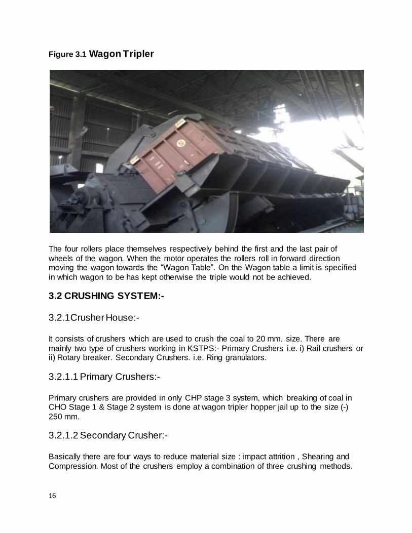
Figure 3.1 Wagon Tripler
The four rollers place themselves respectively behind the first and the last pair of
wheels of the wagon. When the motor operates the rollers roll in forward direction moving the wagon towards the “Wagon Table”. On the Wagon table a limit is specified
in which wagon to be has kept otherwise the triple would not be achieved.
3.2 CRUSHING SYSTEM:- 3.2.1Crusher House:- It consists of crushers which are used to crush the coal to 20 mm. size. There are
mainly two type of crushers working in KSTPS:- Primary Crushers i.e. i) Rail crushers or ii) Rotary breaker. Secondary Crushers. i.e. Ring granulators.
3.2.1.1 Primary Crushers:- Primary crushers are provided in only CHP stage 3 system, which breaking of coal in CHO Stage 1 & Stage 2 system is done at wagon tripler hopper jail up to the size (-)
250 mm.
3.2.1.2 Secondary Crusher:- Basically there are four ways to reduce material size : impact attrition , Shearing and
Compression. Most of the crushers employ a combination of three crushing methods.

17
Ring granulators crush by compressing accompanied by impact and shearing.The unique feature of this granulator is the minimum power required for tone for this type of
material to be crushed compared to that of other type of crushers.
3.3 Construction & Operation:- Secondary crushers are ring type granulators crushing at the rate of 550 TPH / 750 TPH for input size of 250 mm. and output size of 20 mm. The crusher is coupled with motor and gearbox by fluid coupling. Main parts of granulator like break plates, cages crushing
rings and other internal parts are made of tough manganese (Mn) steel. The rotor consists of four rows of crushing rings each set having 20 Nos. of toothed rings and 18
Nos. of plain rings. In CHP Stage 1 & 2 having 64 Nos. of ring hammers. These rows are hung on a pair of suspension shaft mounted on rotor discs. Crushers of this type employ the centrifugal force of swinging rings stroking the coal to produce the crushing
action. The coal is admitted at the top and the rings stroke the coal downward. The coal discharges through grating at the bottom.
3.4 CONVEYING SYSTEM:- 3.4.1 Stacker Reclaimer:- The stacker re-claimer unit can stack the material on to the pipe or reclaim the stack filed material and fed on to the main line conveyor. While stacking material is being fed
from the main line conveyor via tripler unit and vibrating feeder on the intermediate conveyor which feds the boom conveyor of the stacker cum reclaimer. During reclaiming the material dis discharged on to the boom conveyor by the bucket fitted to
the bucket wheel body and boom conveyor feeds the material on the main line conveyor running in the reverse direction
.
3.5 Conveyor belt Specification of Stacker / Reclaimer:- Belt width. : 1400 mm. Speed. : 2.2 m/second.
Schedule of motor : All 3-Ø induction motors. Bucket wheel motor : 90 KW. Boom Conveyor motor : 70 KW.
Intermediate Conveyor Motor : 90 KW. Boom Housing Motor : 22 KW.
Slewing assembly. : 10 KW. Travel Motor : 7.5 KW. Vibrating Feeder. : 2x6 KW.
Total installed power. : 360 KW.

18
CHAPTER -4
ASH HANDLING PLANT
This plant can be divided into 3 sub plants as follows:-
1) Fuel and Ash Plant. 2) Air and Gas Plant. 3) Ash Disposal and & Dust Collection Plant.
4.1 Fuel and ash plant:- Coal is used as combustion material in KTPS, In order to get an efficient utilization of
coal mills. The Pulverization also increases the overall efficiency and flexibility of boilers. However for light up and with stand static load , oil burners are also used. Ash produced as the result of combustion of coal is connected and removed by ash handling
plant. Ash Handling Plant at KTPS consists of specially designed bottom ash and fly ash in electro static precipitator economizer and air pre-heaters hoppers.
4.2 Air & Gas Plant:- Air from atmosphere is supplied to combustion chamber of boiler through the action of forced draft fan. In KTPS there are two FD fans and three ID fans available for draft
system per unit. The air before being supplied to the boiler passes through preheater where the flue gases heat it. The pre heating of primary air causes improved and intensified combustion of coal. The flue gases formed due to combustion of coal first
passes round the boiler tubes and then it passes through the super heater and then through economizer . In re-heater the temperature of the steam (CRH) coming from the
HP turbines heated with increasing the number of steps of re-heater the efficiency of cycle also increases. In economizer the heat of flue gases raises the temperature of feed water. Finally the flue gases after passing through the Electro-Static Precipitator is
exhausted through chimney.
4.3 Ash Disposal & Dust Collection Plant:- BTPS has dry bottom furnace. Ash Handling Plant consists of especially designed bottom and fly ash system for two path boiler. The system for both units is identical and following description is applied to both the units the water compounded bottom ash
hopper receives the bottom ash from the furnace from where it is stores and discharged through the clinker grinder. Two slurry pumps are provided which is common to both
units & used to make slurry and further transportation to ash dyke through pipe line.

19
Dry free fly ash is collected in two number of 31 fly ash hoppers which are handled by two independent fly ash system. The ash is removed from fly ash hoppers in dry state is
carried to the collecting equipment where it is mixed with water and resulting slurry sump is discharged
4.4 Utilisation:- Utilisation of coal-ash is always practise than its disposal. There are various methods of utilisation of coal-ash along with established engineering technologies some of them are mentioned below:
1. Manufacturing of building materials.
2. Making of concrete.
3. Manufacturing of pozzuolana cement.
4. Road construction etc. In all the above cases financial constraint discourages the entrepreneurs to take
up the work. In view of the environmental impact of disposal, Government may give attractive subsidy and create marketing facility so that entrepreneurs may come forward
to use as their raw material. Figure 4.1 ASH HANDING PLANT

20
CHAPTER -5
ELECTRO-STATIC PRECIPITATOR
5.1 Scope & Principle of Operation:- For general mankind, today an Eco friendly industry is must. As far as air pollution is concerned now a days various flue gases filter are there in service. The choice depends
on the size of suspended particle matter. These filters are E.S.P. Fabric filter high efficiency cyclone separations and sitelling room. Fop fly ash , where the particle size
vary from 0.75 microns to 100 micron use gradually use E.S.P. to purify the flue gases due to its higher efficiency & low running cost etc. In an ESP the dust lidder gas is passed through an intense electric field, which causes ionization of the gases & they
changed into ion while traveling towards opposite charged electrode get deposited as particles and thus dust is electric deposited an electrode creating the field. It is
continuous process.
5.2 CONTROLLER:- Now a day micro-processor based intelligent controllers are used to regulate the power
fed to the HVR. The controls the firing / ignition angle of the thyristor connected in parallel mode. Input out waves of the controller and HVR are also shown above, which
clearly indicates that average power fed to ESP field can be controlled by variation of the firing angle of thyristor. The output of controller with respect to time is also controlled by microprocessor, so that ESP operation is smooth and efficient . The chars are as
shown. As can be seen in the event of spark between electrode the output of controller is reduced to zero for few millisecond for quenching the spark. Controller also
takes place care of fault in KVR and gives a trapping and non-trapping alarm as per the nature of fault.
5.3 HIGH VOLTAGE RECTIFIER TRANSFORMER:- HVR receives the regulated supply from controller. It steps up to high voltage rectifier. The D.C. supply is fed to E.S.P. field through its negative bushing. The positive bushing so connected to earth through small resistance which forms a current feed back circuit.
A very high resistance column is also connected with negative bushing . It forms the voltage feed back circuit. These two feedback are used in the controller for indication
and control purpose.
5.4 E.S.P. FIELD:- The field consists of emitting and collecting electrodes structure which are totally
isolated from each other and hanging with the top roof of field. The emitting is also isolated from the roof through the support insulators.

21
CHAPTER -6
BOILER
A boiler (or steam generator) is a closed vessel in which water, under pressure is
converted into steam. It is one of the major components of a thermal power plant. A boiler is always designed to absorb maximum amount of heat released in process of combustion. This is transferred to the boiler by all the three modes of heat transfer i.e.
conduction, convection and radiation.
6.1 Boilers are classified as:- 6.1.1 Fire tube boiler: - In this type the products of combustion pass through the tubes which are surrounded by
water. These are economical for low pressure only.
6.1.2 Water tube boiler:- In this type of boiler water flows inside the tubes and hot gases flow outside the tubes. These tubes are interconnected to common water channels and to steam outlet. The water tube boilers have many advantages over the fire tube boilers
High evaporation capacity due to availability of large heating surface.
Better heat transfer to the mass of water.
Better efficiency of plant owing to rapid and uniform circulation of water in tubes.
Better overall control.
Easy removal of scale from inside the tubes.
In BTPS, Natural circulation, tangentially fired, over hanged type, Water tube boilers are used. Oil burners are provided between coal burners for initial start up and flame
stabilization. Firstly, light oil (diesel oil) is sprayed for initialization then heavy oil (high speed diesel oil) is used for stabilization of flame.
Pulverized coal is directly fed from the coal mills to the burners at the four corners of the furnace through coal pipes with the help of heated air coming from PA fan. Four nos. of ball mills of 34MT/hr. capacity each have been installed for each boiler. The pressure
inside boiler is -ive so as to minimized the pollution and looses & to prevent the accidents outside the boiler. For ensuring safe operation of boilers, furnace safe guard supervisory system (FSSS) of
combustion engineering USA designed has been installed. This equipment systematically feed fuel to furnace as per load requireme. The UV flame scanners
installed in each of the four corners of the furnace, scan the flame conditions and in case of unsafe working conditions trip the boiler and consequently the turbine. Turbine - boiler interlocks safe guarding the boiler against possibility furnace explosion owing to
flame failure.

22
6.2 Furnace: Figure 6.1 furnace
Furnace is primary part of the boiler where the chemical energy available in the fuel is converted into thermal energy by combustion. Furnace is designed for efficient and
complete combustion. Major factors that assist for efficient combustion are the temperature inside the furnace and turbulance, which causes rapid mixing of fuel and
air. In modern boilers, water-cooled furnaces are used.
6.3 PULVERISED FUEL SYSTEM:- The boiler fuel firing system is tangentially firing system in which the fuel is introduced
from wind nozzle located in the four corners inside the boiler. The crushed coal from the coal crusher is transferred into the unit coalbunkers where
the coal is stored for feeding into pulverizing mill through rotary feeder The rotary feeders feed the coal to pulverize mill at a definite rate. Then coal burners are employed to fire the pulverized coal along with primary air into
furnace. These burners are placed in the corners of the furnace and they send horizontal streams of air and fuel tangent to an imaginary circle in the center of the
furnace.
23
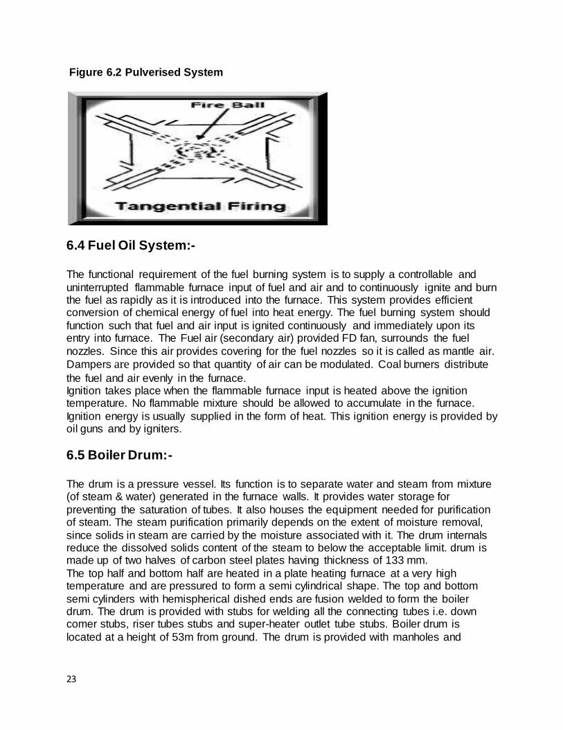
Figure 6.2 Pulverised System
6.4 Fuel Oil System:- The functional requirement of the fuel burning system is to supply a controllable and
uninterrupted flammable furnace input of fuel and air and to continuously ignite and burn the fuel as rapidly as it is introduced into the furnace. This system provides efficient conversion of chemical energy of fuel into heat energy. The fuel burning system should
function such that fuel and air input is ignited continuously and immediately upon its entry into furnace. The Fuel air (secondary air) provided FD fan, surrounds the fuel
nozzles. Since this air provides covering for the fuel nozzles so it is called as mantle air.
Dampers are provided so that quantity of air can be modulated. Coal burners distribute
the fuel and air evenly in the furnace. Ignition takes place when the flammable furnace input is heated above the ignition temperature. No flammable mixture should be allowed to accumulate in the furnace.
Ignition energy is usually supplied in the form of heat. This ignition energy is provided by oil guns and by igniters.
6.5 Boiler Drum:- The drum is a pressure vessel. Its function is to separate water and steam from mixture (of steam & water) generated in the furnace walls. It provides water storage for
preventing the saturation of tubes. It also houses the equipment needed for purification of steam. The steam purification primarily depends on the extent of moisture removal,
since solids in steam are carried by the moisture associated with it. The drum internals reduce the dissolved solids content of the steam to below the acceptable limit. drum is made up of two halves of carbon steel plates having thickness of 133 mm.
The top half and bottom half are heated in a plate heating furnace at a very high temperature and are pressured to form a semi cylindrical shape. The top and bottom
semi cylinders with hemispherical dished ends are fusion welded to form the boiler drum. The drum is provided with stubs for welding all the connecting tubes i.e. down comer stubs, riser tubes stubs and super-heater outlet tube stubs. Boiler drum is
located at a height of 53m from ground. The drum is provided with manholes and

24
manhole covers. Manhole is used for facilitating the maintenance person to go inside the drum for maintenance. Figure 6.3 Steam Drum
The drum form the part of boiler circulating system i.e. movement of fluid from the drum to the combustion zone and back to boiler drum. Feed water is supplied to the drum from the economizer through feed nozzles. Water from the drum goes to water walls
through six down comers. Main parts of boiler drum are:-
Feed pipe
Riser tube
Down comer
Baffle plate
Chemical dosing pipe
Turbo separation
Screen dryer
Drum level gauge
6.6 Draft System:- The combustion process in a furnace can take place only when it receives a steady flow of air and has the combustion gases continuously removed. Theoretically balanced draft
means keeping furnace pressure equal to atmospheric pressure, but in practice the furnace is kept slightly below atmospheric pressure. It ensures that there is no egress of air or hot gas and ash into boiler house.

25
6.7 Draught Fans:- A fan can be defined as volumetric machine which like pumps moves quantities of air or gas from one place to another. In doing this it overcomes resistance to flow by
supplying the fluid with the energy necessary for contained motion. The following fans are used in boiler house.
6.7.1 Primary air fan (P.A. fan) or Exhauster fan- Pulverized coal is directly fed from coal mills to the burners at the four corners of the
furnace through coal pipes with the help of heated air coming from PA fan. Secondly, this fan also dries the coal. Usually sized for 1500 RPM due to high pressure.
6.7.2 Forced draught fan (F.D. fan):- The combustion process in the furnace can take place only when it receives a steady flow of air. This air is supplied by FD fan. Thus FD fan takes air from atmosphere at
ambient temperature & so provides additional draught. Its speed varies from 600-1500 RPM.
6.7.3 Induced draught fan (I.D. fan):- The flue gases coming out of the boiler are passed to the ESP & then dust free gases are discharged up by the chimney to the atmosphere through the ID fan.
6.8 Economizer:- Figure 6.4 Economizer

26
The flue gases coming out of the boiler carry lot of heat. An economiser extracts a part of this heat from the flue gases and uses it for heating the feed water before it enters
into the steam drum. The use of economiser results in saving fuel consumption and higher boiler efficiency but needs extra investment. In an economizer, a large number of
small diameter thin walled tubes are placed between two headers. Feed water enters
the tubes through the other. The flue gases flow outside the tubes.
6.9 Air preheaters:- Air preheaters are employed to recover the heat from the flue gases leaving the economiser and are used to heat the incoming air for combustion. This raises the
temperature of the furnace gases, improves combustion rates an efficiency and lowers the stack (chimney) temperature, thus improving the overall efficiency of the boiler.
Cooling of flue gases by 20% raises the plant efficiency by 1%. Figure 6.5 air pre-heater
Air preheaters are employed to recover the heat from the flue gases leaving the
economiser and are used to heat the incoming air for combustion. This raises the temperature of the furnace gases, improves combustion rates and efficiency and lowers the stack (chimney) temperature, thus improving the overall efficiency of the boiler.

27
Cooling of flue gases by 20% raises the plant efficiency by 1%. In BTPS regenerative type of preheater is used. They use a cylindrical rotor made of
corrugated steel plate. The rotor is placed in a drum which is divided into two compartments, i.e. air compartment (primary air coming from primary air fan and
secondary air for air coming from FD fan with + ive pressure) and flue gases (from economizer with – ive pressure) compartments. To avoid leakage from one compartment to other seals are provided.
The rotor is fixed on an electrical shaft rotating at a speed of 2 to 4 rpm. As the rotor rotates the flue gases, are pass through alternatively gas and air zone. The rotor
elements are heated by flue gases in their zone and transfer the heat to air when they are in air zone. The air temperature required for drying in the case of coal-fired boiler decided the size of the air heaters.
6.10 Super heater:- Superheated steam is that steam, which contains more heat than the saturated steam
at the same pressure i.e. it, has been heated above the temperature corresponding to its pressure. This additional heat provides more energy to the turbine and thus the electrical power output is more.
A superheater is a device which removes the last traces of moisture from the saturated steam leaving the boiler tubes and also increases its temperature above the saturation
temperature. The steam is superheated to the highest economical temperature not only to increase the efficiency but also to have following advantages –
Reduction in requirement of steam quantity for a given output of energy owing to its
high internal energy reduces the turbine size.
Superheated steam being dry, turbine blades remain dry so the mechanical
resistance to the flow of steam over them is small resulting in high efficiency.
No corrosion and pitting at the turbine blades occur owing to dryness of steam.
6.11 Re-heater:- Re-heaters are provided to raise the temperature of the steam from which part of energy has already been extracted by HP turbine. This is done so that the steam remains dry as far as possible through the last stage of the turbine. A re-heater can also
be convection, radiation or combination of both.
6.12 Circulation System:- In natural circulation system, water delivered to steam generator from header, which are at a temperature well below the saturation value corresponding to that pressure. After header, it is delivered to economizer, which heated to above the
saturation temperature. From economizer the water enters the drum and thus joins the circulation system through down covering water wall tubes. In water wall tubes a part of
the water is converted to steam due to boiler and the mixture flows back to the drum. In

28
the drum, the steam is separated out through the steam separators and passed to the super heater. After the super heater when the steam temperature becomes high and
pressure upto 150 Kg./cm3 steam is allowed to enter the turbine to convert potential
energy to kinetic energy.
6.13 Soot Blower:- The boiler tubes are cleaned with the help of steam by the process called soot blowing.
We are well known that a greater no. of tubes are presented inside the boiler. Slowly and slowly the fine ash particles are collected on the tube surface and from a layer this is called soot. Soot is a thermal insulating material.
There are mainly three types of soot blower are used in BTPS: - Water wall soot blower
Super heater soot blower
Air pre heater soot blower
6.14 TECHNICAL SPECIFICATION OF BOILER 1.Type : Direct fired, natural circulation
2. No. of Units. : Two. 3.Make : BHEL.
4.Capacity. : 375 tonnes per hour. 5.Steam Pressure. : 139 Kg./Cm2
6.Efficiency : 86.6 %.
7.No. of fans in service. a) ID fans. : 2 Nos.
b) FD fans. : 2 Nos. c) PA fans. : 2 Nos. d) Seal Air fan. : 1 No.
e) Scanner Air fan. : 1 No. f) Igniter fan. : 1 No. [27]
8. Steam Temperature : 540oC. 9. No. of coal mills in : 3 Nos. service.
10. No. of soot blowers : 70 Nos.
FUEL :- A) COAL:- Type : Slack Coal.
Quantity consumed : 3074 tones per day. Type of handing. : Conveyor.
Ash disposal : Wet system. B) OIL:- Type. : HSD and fuel oil.
Quantity. : a) HSD – 5520 KL per year.
29
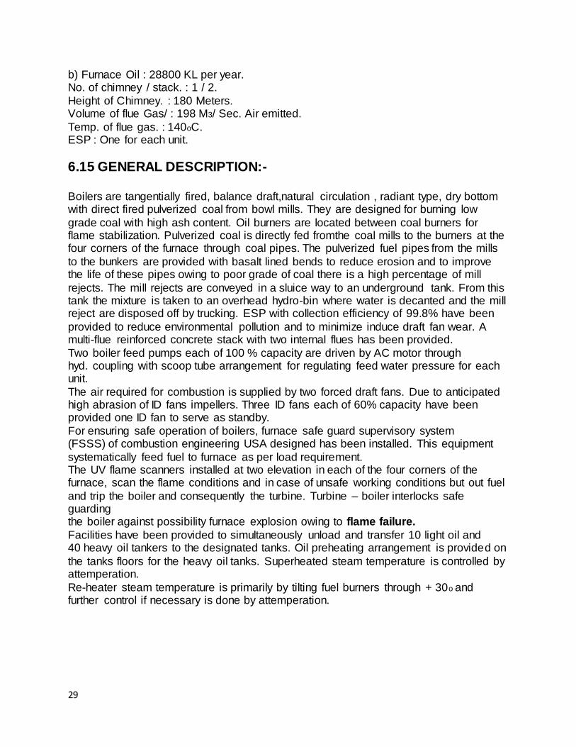
b) Furnace Oil : 28800 KL per year. No. of chimney / stack. : 1 / 2.
Height of Chimney. : 180 Meters. Volume of flue Gas/ : 198 M3/ Sec. Air emitted.
Temp. of flue gas. : 140oC. ESP : One for each unit.
6.15 GENERAL DESCRIPTION:- Boilers are tangentially fired, balance draft,natural circulation , radiant type, dry bottom with direct fired pulverized coal from bowl mills. They are designed for burning low
grade coal with high ash content. Oil burners are located between coal burners for flame stabilization. Pulverized coal is directly fed fromthe coal mills to the burners at the four corners of the furnace through coal pipes. The pulverized fuel pipes from the mills
to the bunkers are provided with basalt lined bends to reduce erosion and to improve the life of these pipes owing to poor grade of coal there is a high percentage of mill
rejects. The mill rejects are conveyed in a sluice way to an underground tank. From this tank the mixture is taken to an overhead hydro-bin where water is decanted and the mill reject are disposed off by trucking. ESP with collection efficiency of 99.8% have been
provided to reduce environmental pollution and to minimize induce draft fan wear. A multi-flue reinforced concrete stack with two internal flues has been provided.
Two boiler feed pumps each of 100 % capacity are driven by AC motor through hyd. coupling with scoop tube arrangement for regulating feed water pressure for each unit.
The air required for combustion is supplied by two forced draft fans. Due to anticipated high abrasion of ID fans impellers. Three ID fans each of 60% capacity have been provided one ID fan to serve as standby.
For ensuring safe operation of boilers, furnace safe guard supervisory system (FSSS) of combustion engineering USA designed has been installed. This equipment
systematically feed fuel to furnace as per load requirement. The UV flame scanners installed at two elevation in each of the four corners of the furnace, scan the flame conditions and in case of unsafe working conditions but out fuel
and trip the boiler and consequently the turbine. Turbine – boiler interlocks safe guarding the boiler against possibility furnace explosion owing to flame failure.
Facilities have been provided to simultaneously unload and transfer 10 light oil and 40 heavy oil tankers to the designated tanks. Oil preheating arrangement is provided on
the tanks floors for the heavy oil tanks. Superheated steam temperature is controlled by attemperation.
Re-heater steam temperature is primarily by tilting fuel burners through + 30o and further control if necessary is done by attemperation.

30
CHAPTER – 7
STEAM TURBINE
INTRODUCTION:- Turbine is a machine in which a shaft is rotated steadily by impact or reaction of current or stream of working substance (steam, air, water, gases etc) upon blades of a wheel. It converts the potential or kinetic energy of the working substance into mechanical power
by virtue of dynamic action of working substance. When the working substance is steam it is called the steam turbine.
Figure 7.1 steam turbine

31
7.1 PRINCIPAL OF OPERATION OF STEAM TURBINE:- Working of the steam turbine depends wholly upon the dynamic action of Steam. The steam is caused to fall in pressure in a passage of nozzle: doe to this fall in
pressure a certain amount of heat energy is converted into mechanical kinetic energy and the steam is set moving with a greater velocity. The rapidly moving particles of steam, enter the moving part of the turbine and here suffer a change in direction of
motion which gives rose to change of momentum and therefore to a force. This constitutes the driving force of the machine. The processor of expansion and direction
changing may occur once or a number of times in succession and may be carried out with difference of detail. The passage of steam through moving part of the commonly called the blade, may take place in such a manner that the pressure at the outlet side of
the blade is equal to that at the inlet inside. Such a turbine is broadly termed as impulse turbine. On the other hand the pressure of
the steam at outlet from the moving blade may be less than that at the inlet side of the blades; the drop in pressure suffered by the steam during its flow through the moving causes a further generation of kinetic energy within the blades and adds to the
propelling force which is applied to the turbine rotor. Such a turbine is broadly termed as impulse reaction turbine.
The majority of the steam turbine have, therefore two important elements, or Sets of such elements . These are (1) the nozzle in which the system expands from high pressure end a state of comparative rest to a lower pressure end a status of
comparatively rapid motion. The blade or deflector , in which the steam particles changes its directions and hence its momentum changes . The blades are attach to the rotating elements are attached to the
stationary part of the turbine which is usually termed the stator, casing or cylinder. Although the fundamental principles on which all steam turbine operate the same, yet
the methods where by these principles carried into effect very end as a result, certain types of turbine have come into existence. 1. Simple impulse steam turbine.
2. The pressure compounded impulse turbine. 3. Simple velocity compounded impulse turbine.
4. Pressure-velocity compounded turbine. 5. Pure reaction turbine. 6. Impulse reaction turbine.
7.2 Description of Steam Turbines:- 7.2.1 Steam flow:- 210 MW steam turbine is a tandem compound machine with HP, IP & LP parts. The
HP part is single flow cylinder and HP & LP parts are double flow cylinders. The individual turbine rotors and generator rotor are rigidly coupled. The HP cylinder has a

32
throttle control. Main steam is admitted before blending by two combined main stop and control valves. The HP turbine exhaust (CRH) leading to reheated have tow swing
check valves that prevent back flow of hot steam from reheated, into HP turbine. The steam coming from reheated called HRH is passed to turbine via two combined stop
and control valves. The IP turbine exhausts directly goes to LP turbine by cross ground pipes.
7.2.2 HP Turbine:- The HP casing is a barrel type casing without axial joint. Because of its rotation symmetry the barrel type casing remain constant in shape and leak proof during quick
change in temperature. The inner casing too is cylinder in shape as horizontal joint flange are relieved by higher pressure arising outside and this can kept small. Due to this reason barrel type casing are especially suitable for quick start up and loading.The
HP turbine consists of 25 reaction stages. The moving and stationary blades are inserted into appropriately shapes into inner casing and the shaft to reduce leakage
losses at blade tips.
7.2.3 IP Turbine:- The IP part of turbine is of double flow construction. The casing of IP turbine is split
horizontally and is of double shell construction. The double flow inner casing is supported kinematically in the outer casing. The steam from HP turbine after reheating enters the inner casing from above and below through two inlet nozzles. The centre
flows compensates the axial thrust and prevent steam inlet temperature affecting brackets, bearing etc. The arrangements of inner casing confines high steam inlet
condition to admission branch of casing, while the joints of outer casing is subjected only to lower pressure and temperature at the exhaust of inner casing. The pressure in outer casing relieves the joint of inner casing so that this joint is to be sealed only
against resulting differential pressure.
The IP turbine consists of 20 reaction stages per flow. The moving and stationary blades are inserted in appropriately shaped grooves in shaft and inner casing.
7.2.4 LP Turbine:- The casing of double flow type LP turbine is of three shell design. The shells are axially split and have rigidly welded construction. The outer casing consist of the front and rear
walls , the lateral longitudinal support bearing and upper part. The outer casing is supported by the ends of longitudinal beams on the base plates
of foundation. The double flow inner casing consist of outer shell and inner shell. The inner shell is attached to outer shell with provision of free thermal movement. Steam admitted to LP turbine from IP turbine flows into the inner casing from both sides
through steam inlet nozzles.

33
CHAPTER – 8
TURBO GENERATOR
8.1.1 THEORY TURBO GENERATOR manufactured by B.H.E.L. and incorporated with most modern design concepts and constructional features, which ensures reliability, with
constructional & operational economy. The generator stator is a tight construction, supporting & enclosing the stator windings,
core and hydrogen coolers. Cooling medium hydrogen is contained within frame & circulated by fans mounted at either ends of rotor. The generator is driven by directly coupled steam turbine at a speed of 3000 r.p.m. the Generator is designed for
continuous operation at the rated output. Temperature detectors and other devices installed or connected within then machine, permit the windings, teeth core & hydrogen
temperature, pressure & purity in machine under the conditions. The source of excitation of rotor windings is thyristor controlled D.C. supply. The auxiliary equipment‟s supplied with the machine suppresses and enables the control of hydrogen pressure
and purity, shaft sealing lubricating oils. There is a provision for cooling water in order to maintain a constant temperature of coolant (hydrogen) which controls the temperature
of windings.
8.1.2 STATOR FRAME The stator frame of welded steel frame construction, which gives sufficient & necessary
rigidity to minimize the vibrations and to withstand the thermal gas pressure. Heavy end shields enclose the ends of frame and form mounting of generator bearings and radial shaft seals. Ribs subdivide the frame and axial members to form duct from which the
cooling gas to & fro radial ducts in the core and is re-circulated through internally mounted coolers. All the gas ducts are designed so as to secure the balanced flow of
hydrogen to all parts of the core. The stator constructed in a single piece houses the core and windings. The horizontally mounted water cooled gas coolers being so arranged that it may be
cleaned on the water side without opening the machine to atmosphere. All welded joints exposed to hydrogen are specially made to prevent leakage. The complete frame is
subjected to hydraulic test at a pressure of 7 ATA.
8.1.3 STATOR CORE It is built up of special sheet laminations and whose assembly is supported by a special
guide bass. The method of construction ensures that the core is firmly supported at a large number of points on its periphery. The laminations of high quality silicon steel
which combines high permeability with low hysteresis and eddy current losses. After stamping each lamination is varnished on both sides with two coats. The segment of
34
insulating material is inserted at frequent intervals to provide additional insulation. The laminations are stamped out with accurately fine combination of ties. Laminations are
assembled on guide bass of group separated by radial ducts to provide ventilation passage. The ventilation ducts are disposed so as to distribute the gas evenly over the
core & in particularly to give adequate supports to the teeth. At frequent intervals during stacking the assembled laminations are passed together in powerful hydraulic press to ensure tight core which is finally kept between heavy clamping plates which are non-
magnetic steel. Use of non-magnetic steel reduces considerably by heating of end iron clamping. The footed region of the core is provided by pressing figures of non-magnetic
steel, which are welded to the inner periphery of the clamping plates. In order to reduce the losses in the ends packets special dampers are provided at either ends of core. Mostly dampers are provided to prevent hunting in ac machines.
8.1.4 STATOR BARS Stator bars are manufactured as half bars. Each stator half coil is composed of double
glass cover and bars of copper transposed in straight portion of “Robill Method” so that each strip occupies every radial portion in the bar. For an equal length along the bar. They are made in strips to reduce skin effect. The winding overhead is in volute shape.
The overhung portion of the bar is divided into four quadrants & insulated. The arrangement reduces additional losses due to damping currents which otherwise be
present due to selfinduced non-uniform flux distribution in the coil slots. The main distribution for the bar consists of resin rich mica loosed thermosetting epoxy. This has excellent mechanical and electrical properties & does not require any impregnation. Its
moisture absorbing tendency is very low and behavior of mica is for superior than any other conventional tape insulation system. Semi-conductor coating is also applied to a part of overhung with a straight overlap of conductive coil in the sides to reduce eddy
currents to minimum. Conductor material is electrolytic copper connections brazed with free coating silver alloy to obtain joints, which are both electrically & mechanically
sound.
8.1.5 STATOR WINDINGS Stator windings are double star layers, lap wound, three phase, and short pitch type.
The top & bottom are brazed and insulated at either end to form turns. Several such turns form a phase. Phases are connected to form a double star winding. The end of
winding form involutes shape ends, inclined towards machine axis by 20o, thus form a basket winding with total induced conical angle of 400 . Due to this stray load losses in the stator ends to zero. The arrangement of complete stator winding electrical circuit is
viewed from turbine end of generator & rotor windings. Slot numbering is clockwise from turbine end. A thick line identifies the top bar in slot No.1. End windings will be sealed
against movement of short circuit by both axial & peripheral bracing. The later consists of hardened glass laminated blocks inserted between adjacent coil sides in coil overhangs, so that with the coils, they form a continuous rigid ring. Glass cord or top is
used lashing the packing of blocks. The complete assembly is secured b y high tensile brass blots. The winding is designed to withstand short circuit stresses. The exposed

35
portion of windings is finally coated. Insulation of individual bars & stator windings at various stresses is tested with applied high voltages of AC of Hz.
8.1.6 TERMINAL BUSHINGS Six output leads (3 long, 3 short) have been brought out of the coming on the exciter
side. External connections are to be made to the three shorter terminals, which are phase terminals. The large terminals are of neutral & current transformer is inserted. The conductor of Generator terminal bushing having hollow copper tubes with Copper
brazed atthe ends to avoid leakage of hydrogen. Hollow portions enable bushings to be hydrogen cooled. Ends of bushings are Silver-plated: middle portion of the bushing is
adequately insulated & has a circular flange for bolting the stator casing. Gaskets are provided between the Flange of terminal bushings and castings to make it absolutely gas tight.
8.1.7 BEARINGS Generator bearings have electrical seats of consists of steel bodies with removable steel pads. The bearings are formed for forced lubrication of oil at a pressure of 2-3
ATM/ from the same pump that supplies oils to the turbine, bearings & governing gears. There is a provision to ensure & measure the rotor bearing temperature by inserting a
resistance thermometer in the oil pockets.
8.1.8 VENTILATION SYSTEM The machine is designed with ventilation system having 2 ATM rated hydrogen
pressure. Two axial fans mounted on either side of the rotor to ensure circulation of hydrogen. The stator is designed for radial ventilation by stem. The end stator core packets & core clamping & plates are intensively cooled by Hydrogen through special
ventilation system. Design of special ventilation is so as to ensure almost uniform temperature of rotor windings and stator core. Rated load operating temperature is well
within the limits corresponding to the Class B operation. Embedded Resistance Temperature Detectors do continuous monitoring of Hydrogen temperature at active parts of Generator.
8.1.9 RESISTANCE TEMPERATURE DETECTORS (R.T.D.) An R.T.D. is a point resistance element. Operation of R.T.D. depends on the principal
that electrical resistance of metallic conductor varies linearly with temperature.
8.1.10 APPLICATIONS RTD & its associated equipments are designed for use with Generator to determine
temperature at various parts & places. The equipment‟s consists of two parts:-
36
1. Switch Board Equipment: is usually includes a temperature indicating meter, test
resistor transfer switch & leads.
2. Machine Equipment: is usually includes temperature R.T.D.leads and terminal
blocks with grounding connections. Leads from RTD are brought out to the terminal board by cables through conduits to
protect them from physical damage and from contact with high voltage coils. Some RTDs are in stator teeth with 7 spacers, 7 RTDs between the coil sides in stator slots with 7 spacers
and 3 RTDs are there in the stator core with spacers. The location of RTDs is in three phase‟s i.e. in the centre of machine, in each region of machine and midway between
them. The detectors in the stator slots are distributed uniformly in all three phases. Measurement of temperature of Hydrogen cooling water for Hydrogen coolers & metals is as:
Six RTDs are provided at the inlets of each of six individual Hydrogen cooler elements for measurement of temperature of Hydrogen, similarly Six RTDs are provided at the
outlets also. One RTD along-with one spacer is provided in the lower part of stator frame for measurement & signalization of hot Hydrogen. Six RTDs are provided at outlets of each of six individual Hydrogen Cooler elements for measurement of
temperature of cooling water at the outlet.
8.1.11 MEASUREMENT OF BEARING TEMPERATURE Two RTDs are provided in the shelves of Turbo-Generator for measurement of
signalization of the bearing metal cap. All the terminals of RTDs are brought out to a common terminal board located on the stator frame.
8.1.12 HYDROGEN COOLERS Three Hydrogen Coolers each comprising of two individual units are mounted inside the stator frame. The inlet and outlet of cooling water from both of machine i.e. from
nondriving side as well as turbine side. The Clearing of the individual cooler element can be carried out from both ends of the Generator even during operation. The
assembly of individual cooler elements in stator frame is however carried out only from the non-driving side.
8.2 ROTOR
Rotor shaft consists of single piece alloy steel forging of high mechanical and magnetic properties performance test includes :- 1. Tensile test on specimen piece.
2. Surface examination. 3. Sulfur prist tests.
4. Magnetic crack detection. 5. Visual examination of bore.

37
6. Ultrasonic examination. Slots are milled on the rotor gorging to receive the rotor winding. Transverse slots
machined in the pole faces of the rotor to equalize the moment of inertia in direct and quadrilateral axis of rotor with a view minimizing the double frequency.
8.2.1 VIBRATION OF ROTOR The fully brazed rotor is dynamically balanced and subject to 120 % over speed test at the work balancing tunnel so as to ensure reliable operation.
8.2.2 ROTOR WINDINGS Rotor winding is of direct coil type and consists of parallel strips of very high conductivity Silver Bearing Copper, bent on edge to form coil. The coils are placed in impregnated
glass, laminated short shells; using glass strips inter turn insulation and will be brazed at the end to form continuous winding. The complete winging will be packed at high
temperature and pressed to size by heavy steel damping rings. When the windings have cooled, heavy dove tail wedges of non-magnetic materials will seal the insulation at the top of slot portion. The cooling medium hydrogen gas will be brought in direct
contact with copper by means of radial slots in embedded portion. Treated glass spacers inserted between the coils and solid ring prevent lateral movement of coil
overhang. The formation and description of glass spacer is such as to leave ample space for ventilation.
8.2.3 BEARINGS
The bearings are self-aligned & consist of slip steel shells linked with special bearing metal having very low coefficient of friction. The bore is machined on an elliptical shape
so as to increase the mechanical stability of the rotor. The bearings are pressure lubricated from the turbine oil supply. Special precautions are taken to prevent oil & oil vapor from shaft seals and bearing along the shaft. The circulation of shaft current is
liable to damage. The bearing surface is protected by insulation so placed that the bearings, seals &
necessary pipes are inclined from the frame.
8.2.4 SLIP RINGS The slip rings are made of forged steel. They are located at either side of Generator
Shaft. The slip ring towards the exciter side is given +ve polarity initially. They have helical grooves and skewed holes in the body for cooling purpose by air. Calibrated mica is first built up to required thickness on the shaft where slip rings are located. The
slip rings are insulated from the rotor shaft. Excitation current is supplied to the rotor winding. Through the slip rings, which are connected to the winding. On one end and to
the slip ring on the other end with insulated (terminal) studs passing „though‟ the radial holes in the rotor shaft.

38
The terminal studs at both the ends of excitation leads are fitted gas cat seals to prevent leakage.
8.2.5 BUSH GEAR ASEMBLY Generator bushes are made from the various compositions of natural graphite and binding material. They have a low coefficient of friction and are self lubricating. The
brushes are provided with a double flexible copper or pigtails. A helical spring is mounted rapidly over each bush so that pressure is applied on the centerline of bush. A
metal cap is riveted to the brass bead and is provided with a hole to maintain the position of the spring plug. Several brush holder, each carrying on brush in radial position are fixed to a silver plated copper studs mounted on the collecting arm
concentric with each slip rings. The collecting arm is made out of a copper strip.
8.2.6 DRYING OF WINDING
Generator stator bars are insulated with mica insulation, which is homogeneous in nature and practically impervious to moisture, and reduce time required to draught. The insulation resistance of the stator phase winging against earth and with reference to
other phases under hot condition shall not be less than the value obtained automatically.
Rin = μ/(s/100+1000) m 52 U = rated winding Voltage under test.
Rin = insulation resistance under hot conditions Rated o/p of turbo generator.
The insulation resistance of entire excitation system circuit. In hot condition must not fall below 0.5 m 52. The insulation resistance in calculated as per the formula: Rin = Rv (U1 +U2) / (U-1)
Rin = Insulation resistance of exciter () Rv = Internal resistance of voltmeter ()
U1 = Voltage measured btw. Slip ring & shaft/ earth (volts). When starting the drying process, the winding insulation resistance will usually decrease when the drying process becomes effective; the insulation will gradually
increase.

39
Figure 8.1 CROSS SECTIONAL VIEW OF TURBO GENERATOR

40
CHAPTER – 9
COOLING SYSTEM
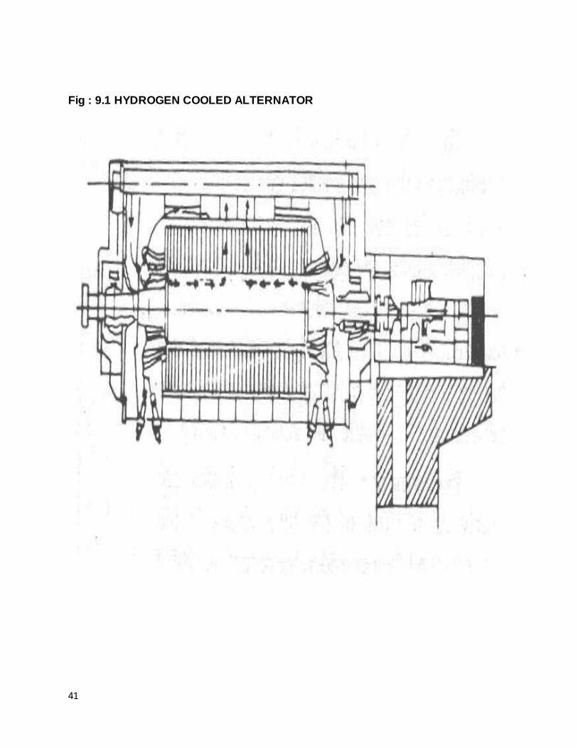
9.1 INTRODUCTION:- In BTPS hydrogen cooling system is employed for generator cooling. Hydrogen is used for cooling medium primarily because of its superior cooling properties & low density.
Thermal conductivity of hydrogen 7.3 times of air. It also has higher transfer co-efficient. Its ability to transfer heat through forced convection is about 75% better than air.
Density of hydrogen is approx. 7/14 of the air at a given temperature and pressure. This reduces the wind age losses in high speed machine like turbogenerator. Increasing the hydrogen pressure the machine improve its capacity to absorb & remote heat. Relative
cooling properties of air and hydrogen are given below :- 1) Elimination of fire risk because hydrogen will not support combustion.
2) Corona discharge is not harmful to insula. since oxidation is not possible. 3) Smooth operation of machine in view of vertical elimination of wind age noise & the use of heavy gas light enclosure and dirty probe casing. At pressure 0.035 atm. of
hydrogen heat carrying capacity is 1. But at 2.0atm. of hydrogen heat carrying capacity is 1.95 to overcome the serious possibility of hydrogen explosion with in the machine
and to ensure the safety of operation purity of hydrogen on the generator. Casing must be maintained as high as possible. The purity of hydrogen should be 98% above but should not be less than 98% . In case of hydrogen purity drops below 98% an alarm is
provided.
9.2 HYDROGEN DRYERS:- Two nos. of dryers are provided to absorb the hydrogen in the Generator. Moisture in
this gas is absorbed by silica gel in the dryer as the absorbed gas passes through it. The satural of silica gel is indicated by change in its color from blue to pink. The silica
gel is reactivated by heating. By suitable change over from drier to the other on un-interrupted drying isachieve.
41
Fig : 9.1 HYDROGEN COOLED ALTERNATOR

42
CHAPTER 10
CONTROL ROOM
10.1 MAIN CONTROL ROOM In control room various controls are provided simultaneously various measurement
are made various relays are provided here. Instrumentation Limited Kota is major supplier of apparatus. There is one unit control from which two adjacent unit of 110 MW each can be
controlled. In addition are local panels at the boilers, turbo sets and boiler feed pumps. The operation of unit is basically controlled from unit control room.
The operation of various rents and chain are done locally as per requirement. The unit control room has a set of parameters panel for indicating or recording parameter of boilers or turbo sets.
The parameters recorded in control room included per pr. and temp. of line steam, reheat steam , feed water, fuel oil flow, mill outlet temp. ,mill differential , turbine speed,
control valve operation, turbine shaft , axial shaft , back pressure in condenser , metal temperature etc. There is a data logger to ensure accurate lagging of essential data. The VCB also control panel for one generator and contains exciter synchronizing
arrangement. The unit control room also houses most of electronic regulator, relay, recorders and other devices in near side of room.
10.2 CONTROL PANEL I
12.2.1 FAN CONTROL DESK a) Induced draft fan ( 3 Nos.) at full load and 2 Induce Draft Fans Run.
b) Forced draft fan ( 2 Nos.). c) Primary Air Fan (3 Nos.) at full load. d) Furnace Pressure (- 5 to 10 wcl).
e) Primary Air Header Pressure (750-800 mm. level wcl.) f) FO Wind box pressure or wind box differential pressure.
10.3 CONTROL PANEL II 12.3.1 FUEL CONTROL DESK a) Coal, oil flow. b) Oil pressure.
c) Temp. of mill (inlet & outlet). d) Flow of air. e) Differential Pressure of mill.

43
10.4 CONTROL PANEL III
12.4.1 STEAM & WATER DESK a) Drum Level Control
b) Flow of steam & water. c) Pressure of Steam & Water. d) Temp. of steam and water.
10.5 CONTROL PANEL IV 12.5.1 TURBINE DESK
a) Pressure Control. b) Load Control. c) Speed Control.
d) Effectors, Control Values, Stop Values, Deaerators.
10.6 CONTROL PANEL V
12.6.1GENRATOR CONTROL PANEL a) Voltage Current MVAR. b) Stator Rotor Temp.
c) For Stator Cooling (a) H2 pressure. b) H2O pressure. Fig : 10.1 control room