TRAINING MANUAL - Food and Agriculture · PDF file9 Training Manual on the construction of FRP...
152
Transcript of TRAINING MANUAL - Food and Agriculture · PDF file9 Training Manual on the construction of FRP...


54 Report of the Fifth Meeting of the Governing Council

TRAINING MANUALon
the construction ofFRP beach landing boats
by
John McVeaghFAO Consultant
Thomas AnmarkrudFAO Consultant
Øyvind GulbrandsenFAO Consultant
Revanoor RavikumarRegional Project Coordinator
Per DanielssonGlobal Project Coordinator
andAri Gudmundsson
Fishery Industry Officer (Vessels)Fishing Operations and Technology Service
Fisheries and Aquaculture Resources and Conservation DivisionFAO, Rome
GCP/GLO/200/MUL

2 Training Manual on the construction of FRP beach landing boats
This training manual is one of a series prepared during the course of the projectGCP/GLO/200/MUL. The conclusions and recommendations given in the documentare those considered appropriate at the time of its preparation. They may be modifiedin the light of further knowledge gained at subsequent stages of the project.
The designations employed and the presentation of material in this publication do notimply the expression of any opinion whatsoever on the part of the Food and AgricultureOrganization of the United Nations (FAO) concerning the legal or development statusof any country, territory, city or area or of its authorities, or concerning the delimitationof its frontiers or boundaries. The mention of specific companies or products ofmanufacturers, whether or not these have been patented, does not imply that thesehave been endorsed or recommended by FAO in preference to others of similar naturethat are not mentioned.
The views expressed in this publication are those of the authors and do not necessarilyreflect the views of FAO.
All rights reserved. Reproduction and dissemination of material in this publication foreducational or other non-commercial purposes are authorized without any prior writtenpermission from the copyright holders provided the source is fully acknowledged.Reproduction of material in this publication for resale or other commercial purposes isprohibited without written permission of the copyright holders. Applications for suchpermission should be addressed to: Chief, Electronic Publishing Policy and SupportBranch, Communication Division, FAO, Viale delle Terme di Caracalla, 00153 Rome,Italy, or by e-mail to: [email protected]
© FAO 2010
Cover photo:
The first FRP IND-30 design beach landing boat under construction during the training course at Ayyappa BoatBuilders in Kakinada, Andhra Pradesh, India, under the FAO project “Safety at sea for small-scale fisheries indeveloping countries” (GCP/GLO/200/MUL), funded by the Swedish International Development Cooperation Agency(Sida), the International Maritime Organization (IMO) and the Swedish Maritime Administration (SMA).

3 Training Manual on the construction of FRP beach landing boats
Preparation of this document
This manual has been developed from information collected during the FAO project“Safety at sea for small-scale fisheries in developing countries” (GCP/GLO/200/MUL),funded by the Swedish International Development Cooperation Agency (Sida), theInternational Maritime Organization (IMO) and the Swedish Maritime Administration(SMA).
The manual was partly developed from the FAO Fisheries and Aquaculture TechnicalPaper 507: Fishing boat construction: 4. Building an undecked fibreglass reinforcedplastic boat, by Thomas Anmarkrud. It draws heavily from the experience gained duringa training course conducted in Kakinada, India for FRP boatbuilders and from currentpractices in India and Sri Lanka in building beach landing fishing boats.
Two boats of the FAO IND-30 design were built during the training course. ØyvindGulbrandsen, FAO Consultant Naval Architect, was responsible for the final IND-30design.
3 Training Manual on the construction of FRP beach landing boats

4 Training Manual on the construction of FRP beach landing boats
Abstract
This manual on construction of fibreglass reinforced plastic (FRP) beach landingboats has been prepared primarily to assist small boatyards in Tamil Nadu,India that build beach landing fishing boats, but may also be used as a guide formaking good quality FRP boats as well as for FRP training in the region.
The manual should be seen as a supplement to FRP boatbuilding manualsavailable in the Food and Agriculture Organization of the United Nations (FAO)and other international publications. It assumes prior knowledge of FRP handlay-up processes and terms generally used in the industry.
Recommendations on working conditions, materials and quality control are basedon tropical ambient conditions and the type of boatyards likely to build suchboats.
Part I of the manual contains general information on FRP materials, handlingand working conditions. Part II describes the building of a hull plug and a mouldand Part III describes the building of a beach landing boat. Finally, Part IV containsinformation on manufacturing defects and repairs.
The manual has four annexes that provide further information related to FRPboatbuilding. Annexes 1 and 2 contain a bibliography and a glossary, respectively.All drawings for the FAO IND-30 boat design are provided in Annex 3. Finally,Annex 4 contains the draft recommended construction standards for FRPfishing vessels. These standards are a part of the FAO/ILO/IMO Safetyrecommendations for decked fishing vessels of less than 12 m in length andundecked fishing vessels, which are currently under development.
5 Training Manual on the construction of FRP beach landing boats
Contents
Acronyms .................................................................................................................................. 6
Acknolwedgements ................................................................................................................... 7
Introduction ................................................................................................................................ 9
Part I - General Information1 Fibreglass Reinforced Plastic ................................................................................... 13
2 Material Description and Handling ............................................................................ 13
3 Workshop Facilities .................................................................................................. 18
4 Tools to be Used....................................................................................................... 19
5 Basic Laminate Building ........................................................................................... 22
6 Quality ...................................................................................................................... 25
7 Health and Safety Issues .......................................................................................... 26
Part II - Building and Plugs and Moulds8 Making the Hull Plug ................................................................................................. 32
9 Making the Mould ..................................................................................................... 38
Part III - Building an FRP Beach Landing Boat10 Building an FRP Beach Landing Boat ....................................................................... 42
Part IV - Manufacturing Defects and Repairs11 Manufacturing Defects ............................................................................................. 64
12 Repairs ..................................................................................................................... 65
Annex 1 - Bibilography ............................................................................................................. 73
Annex 2 - Glossary .................................................................................................................. 74
Annex 3 - Drawings ................................................................................................................. 77
Annex 4 - FRP Construction Standards ................................................................................. 127
Appendix 1 - Illustration of Terms used in the Definitions ....................................................... 128
Appendix 2 - Recommended Construction Standards for GRP Fishing Vessels .................... 131
5 Training Manual on the construction of FRP beach landing boats

6 Training Manual on the construction of FRP beach landing boats
Acronyms
BLC Beach landing craft
BOBP-IGO Bay of Bengal Programme Inter-Governmental Organisation
CIFNET Central Institute of Fisheries Nautical and Engineering Training
CSM Chopped strand mat
FAO Food and Agriculture Organization of the United Nations
FRP Fibreglass reinforced plastic
ILO International Labour Organization
IMO International Maritime Organization
MEKP Methyl ethyl ketone peroxide
MEK Methyl ethyl ketone
PVA Polyvinyl alcohol
PVC Polyvinyl chloride
Sida Swedish International Development Cooperation Agency
WR Woven roving

7 Training Manual on the construction of FRP beach landing boats
AcknowledgementsThe authors gratefully acknowledge the important contributions of many expertswith fiberglass reinforced plastic (FRP) boatbuilding experience, includingV Babu Rao, National FRP Consultant, for his excellent support during thetraining and boatbuilding exercise in Kakinada, Andhra Pradesh, India, as wellas Ayyappa Boat Builders for providing the infrastructure.
Special thanks are also due to BOBP-IGO and its Director, Dr Yugraj SinghYadava, for their excellent logistic support to the FRP boatbuilding trainingcourses in obtaining trainee nominations from the Department of Fisheries ofthe Governments of Tamil Nadu, Andhra Pradesh and the Union Territory ofPuducherry, contracting Ayyappa Boat Builders and local backstopping.
Several of the photos and illustrations used in this manual have been providedby Thomas Anmarkrud during the preparation of FAO Fisheries and AquacultureTechnical Paper 507: Fishing boat construction: 4. Building an undeckedfibreglass reinforced plastic boat. Photos were also provided by other authors,including V. Babu Rao, during the training course in Kakinada.
7 Training Manual on the construction of FRP beach landing boats

8 Training Manual on the construction of FRP beach landing boats

9 Training Manual on the construction of FRP beach landing boats
Introduction
Fibreglass reinforced plastic (FRP) as a material for fishing boatbuilding was introduced in South Asia inthe 1960s. It grew in popularity over the following two decades for two reasons: the escalating cost ofgood boatbuilding timber and the relatively lesser skills required to build small FRP boats.
FRP is ideally suited for mass production and its popularity for mass-built recreational craft in the developedworld is well known. In both India and Sri Lanka, an opportunity was recognized by a few entrepreneursfor manufacturing FRP boats on a large scale. Boatyards using the latest developments and conformingto international standards were set up nearly 30 years ago to cater to the increasing demand for largerharbour-based fishing boats as well as to meet an export demand for recreational craft. In Sri Lanka,nearly all boats built today are made of FRP.
Small-scale fisheries also suffered a steady decline of catch per effort and traditional boats could nolonger provide adequate earnings because of their limited range. FAO, through its Bay of Bengal Programmein the late 1980s, developed a prototype fishing boat suitable for beach-based operations and capable ofan extended range of operation. This was the forerunner of the beach landing craft (BLC) in India. Thegrowing scarcity of suitable timber for traditional beach boats saw the rapid increase of FRP BLC of manysizes and types along the east coast of India in the past two decades.
The flipside to this rapid development was the growing number of FRP boatyards where occupationalsafety and health conditions as well as quality control was unknown. In addition, fishers were unaware ofthe need for strict quality.
The tsunami in December 2004 exacerbated the problem. The huge amount of humanitarian aid, the rushto provide needy fishers with replacement boats and the mushrooming of opportunistic boatyards resultedin FRP fishing boats of even poorer quality. Thousands of boats built after the tsunami were unserviceableafter just a couple of years.
Through the FAO project “Safety at sea for small-scale fisheries in developing countries” (GCP/GLO/200/MUL), funded by the Swedish International Development Cooperation Agency (Sida), the InternationalMaritime Organization (IMO) and the Swedish Maritime Administration (SMA), it was identified that thefirst corrective step required was to establish safety guidelines for construction and to promote goodFRP boatbuilding practices. Development of a training manual addressing the key area of quality controland boat structure was seen as a priority.
This manual draws heavily from the experience gained during a training programme conducted in Kakinada,India for FRP boatbuilders, where two FRP BLC of FAO design IND-30 were built, and from currentpractices in India and Sri Lanka in building beach landing fishing boats.
Recommendations on working conditions, materials and quality control are based on tropical ambientconditions and the type of boatyards likely to build such boats. Many of the hand lay-up processes describedare equally applicable to other FRP boats built in the region.
Using the manualThis FRP manual is prepared for Tamil Nadu, India, but could also be used as a guide formaking good quality FRP boats in the Bay of Bengal region and other regions whereappropriate. Many of the applications are general and will apply to most kinds of FRP boats.
It should be a supplement to FRP boat building manuals and books already available in FAOand other international publications.
This FRP manual assumes that the boatbuilder has some FRP experience and will use goodpractices.
Parts I and II contain general information on FRP boatbuilding and on mould and plug building,respectively. Part III describes the construction of an FRP BLC, used for fishing. Part IVfocuses on FRP maintenance and repair work. Finally, Annexes 1-4 provide a bibliography,glossary, drawings for the FAO IND-30 boat design, and draft recommended constructionstandards for FRP fishing boats, respectively.

10 Training Manual on the construction of FRP beach landing boats

11 Training Manual on the construction of FRP beach landing boats
PART I
GENERAL INFORMATION
12 Training Manual on the construction of FRP beach landing boats

13 Training Manual on the construction of FRP beach landing boats
1 - FIBREGLASS REINFORCED PLASTIC
What is fibreglass reinforced plastic, or FRP? It is a composite of several materials (mainly fibreglassfibres and resin) laid down in alternating layers and hardened to form a solid laminate. By way of comparison,wood fibres in a tree are held together by their natural glue, lignin. Similarly in FRP, layers of fibreglassmaterial are glued together with polyester resin. Both in a tree and in FRP laminate, the fibres give strengthto the structure, and lignin and resin hold the fibres together, creating stiffness and distributing the loadamong the fibres.
If put together correctly, the laminate can be both strong and stiff with good resistance to fatigue and theinfluence of water. If constructed poorly, the laminate might still look good on the surface, but due to itspoor quality, could degrade and collapse in half the expected lifetime or even less.
This basic manual concentrates on the process of preparing the mould and constructing an FRP boat bygluing together layers of bonded fibreglass fibres called chopped strand mat (CSM) with a resin calledgeneral purpose (GP) orthopthalic polyester (“ortho-polyester”). The fibreglass could also be glued togetherwith other resins, like vinylester or epoxy.
The chemical, oil-based resin is toxic and flammable: therefore, safety considerations are important whenworking with this material. These precautions are set out in the following section.
2 - MATERIAL DESCRIPTION AND HANDLING
2.1 FIBREGLASS - CSM (CHOPPED STRAND MAT)
Figure 1
This boatbuilder is saturating the fibres of CSM with polyester resin, using aresin roller.
He is also using a face mask respirator as protection against inhaling toxicfumes.
Figure 2
CSM consists of randomly oriented fibres from25–50 mm (1–2 inches) in length, held togetherwith a styrene soluble polyvinyl acetate binder.
14 Training Manual on the construction of FRP beach landing boats
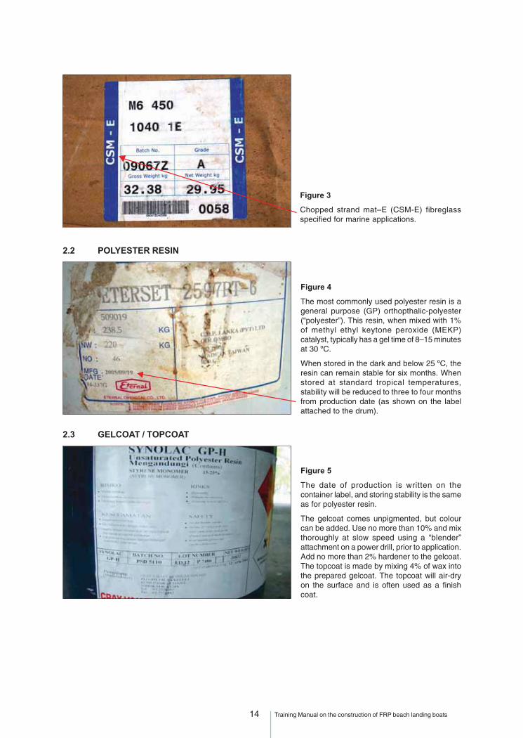
2.2 POLYESTER RESIN
Figure 3
Chopped strand mat–E (CSM-E) fibreglassspecified for marine applications.
Figure 4
The most commonly used polyester resin is ageneral purpose (GP) orthopthalic-polyester(“polyester”). This resin, when mixed with 1%of methyl ethyl keytone peroxide (MEKP)catalyst, typically has a gel time of 8–15 minutesat 30 ºC.
When stored in the dark and below 25 ºC, theresin can remain stable for six months. Whenstored at standard tropical temperatures,stability will be reduced to three to four monthsfrom production date (as shown on the labelattached to the drum).
2.3 GELCOAT / TOPCOAT
Figure 5
The date of production is written on thecontainer label, and storing stability is the sameas for polyester resin.
The gelcoat comes unpigmented, but colourcan be added. Use no more than 10% and mixthoroughly at slow speed using a “blender”attachment on a power drill, prior to application.Add no more than 2% hardener to the gelcoat.The topcoat is made by mixing 4% of wax intothe prepared gelcoat. The topcoat will air-dryon the surface and is often used as a finishcoat.

15 Training Manual on the construction of FRP beach landing boats
2.4 HARDENER / CATALYST
Figure 6
The hardener, or catalyst, is used to make the polyester cure. It is extremelycorrosive, and special care must be taken in handling and storage. Wearsafety glasses and rubber gloves for personal protection.
When hardener and resin are mixed, the chemical reaction generates heat(exotherm). If hardener is spilled in quantity, it may react quickly with othermaterials and cause a fire. Hardener should be stored separately frompolyester.
If accelerator is used to make a fast-cure “fixing putty”, the accelerator mustbe mixed thoroughly with the putty before hardener is added. Mixingaccelerator and hardener together will cause an explosion. Whentemperatures are near 37 ºC, follow the manufacturer’s advice and use aminimum 0.8% of hardener, which will result in a shorter geltime. For ease ofworking, prepare this mixture in smaller batches.
2.5 WAX
Figure 7
When preparing a used mould for fibreglassing, a moderateamount of high quality paste release wax should be spreadon the surface of the mould and then polished to a highgloss with a clean cloth.
When preparing (breaking-in) a new mould, apply five to tenlayers of wax. Polyvinyl alcohol (PVA) may also be used asa mould release before starting the first five products. A goodquality mould should not require use of PVA, and shouldneed only a light waxing and polishing after each demoulding.This gives the best finished results.
2.6 BUFFING COMPOUND
Figure 8
The buffing compound, or paste polish, comes in differentgrades: coarse, fine or superfine. It is used when building upa new high-gloss finish in a mould or repairing an FRP hull.First, the surface is sanded with water and wet sandpaper ingrits from 240 to 1 200 (Figure 15). Second, a coarse pasteis used to polish the surface. Finally, after a thorough washing,the surface is buffed with fine grade paste and polished withwax.
When repairing a mould, the repaired spot has to be sanded,polished and then broken-in, as described above for a newmould.
2.7 ACETONE
Acetone is a liquid solvent, often used to dissolve and remove polyester from brushes, rollers and othertools before the polyester sets up or cures. Acetone can be absorbed through the skin and stored in thebody. It also removes the natural oils that keep skin flexible and healthy. Extensive use of acetone overlong periods without proper protection can have serious health implications. Direct contact should beavoided by using protective gloves when working with acetone. Hands should not be washed in acetone.

16 Training Manual on the construction of FRP beach landing boats
2.8 STYRENE
Styrene is a standard ingredient in polyester resin. It is also a solvent and can be used to lower theviscosity of polyester and gelcoat. While styrene is also necessary for the curing process, more than5 percent should not be used. Higher amounts can unbalance the curing process and weaken the finishedlaminate. When repairing old laminates, a light styrene wipe prior to laminating can improve the bondbetween old and the new polyester laminates. Styrene is also effective for cleaning moulds.
GOOD VENTILATION IS EXTREMELY IMPORTANTWHEN WORKING WITH
POLYESTER RESIN, STYRENE AND ACETONE!THE FUMES CAN BE HARMFUL TO HEALTH!
2.9 POLYURETHANE FOAM
Pourable polyurethane foam (PU) may be used inside thwarts and other hollow cavities for floatation.To make the foam, two liquids, delivered in separate cans A and B, must be mixed in equal amounts (1:1)for proper expansion and cure. The amount of liquid needed to achieve the desired volume should beconfirmed before use. Typically, 1.6 kg of mixed liquid expands into approximately one cubic foot of foam.PU foam also comes in blocks and sheets in variable densities.
Polyester resin can be applied directly onto cured PU foam.
WHEN PU FOAM IS CURING,ICOCYANATE GASES DEVELOP
THAT ARE HARMFUL IF INHALED!
2.10 EXPANDED POLYSTYRENE (STYROFOAM)
This material can also be used for flotation. Styrofoam is generally the cheapest foam available andcomes in blocks and sheets. However, it is easily damaged by solvents and melts on contact with acetone,styrene and gasoline. This means that it is not practical to laminate directly on styrofoam without isolatingit with solvent-proof plastic. Expanded polystyrene also absorbs water when exposed for long periods.It therefore has to be waterproofed, for example, with bitumen emulsion.
2.11 MATERIAL HANDLING AND STORAGE
Precautions to be taken when handling and storing FPR materials include sections 2.11.1 to 2.11.5:
2.11.1 Ordering material
Choose a material supplier who is helpful and experienced. Build a good working relationship with him orher. Materials received should always be checked against those ordered from the supplier. It should neverbe assumed that what arrives is what was ordered. Lot number and date of production and/or expiry must
be checked as soon as the containers arrive. If the product isold or of a different quality than ordered, it should be returned atcost to the supplier. Such cross-checking is important, becauseif the boat breaks down due to use of inappropriate raw materials,the boat owner will blame the builder, not the supplier.
Figure 9
Always check and write down the lot number and the production datewhen receiving storage time-sensitive products.
This information should always be given on the container.
This example shows a 20-kg bucket of gelcoat with requiredinformation on the label.
17 Training Manual on the construction of FRP beach landing boats
2.11.2 Documentation
The supplier should be asked for technical data sheets for each product, which should then be retainedfor future reference. Data sheets should give all the physical and technical properties required by the boatdesigner to produce a quality product. Resins can vary widely in characteristics such as viscosity andstrength. Data sheets also provide key information such as proper mixing ratios and the critical temperatureranges suitable for laminating.
Always keep a record of all material used under the construction.
2.11.3 Fibreglass
Fibreglass (chopped strand mat) should be kept dry and clean. This is of great importance but difficult toachieve in a hot and humid climate. The fibreglass mat should be kept in a dry and ventilated room.If there is much dust or contamination in the air, or if there is a possibility of rain, cover the material in plastic.
2.11.4 Resin, catalyst and accelerator
Polyester and gelcoat should, if possible, be stored at less than 25 ºC. The shelf life becomes greatlyreduced at higher temperatures.
Resin, catalyst and accelerator should be stored separately, in a cool and dry place.
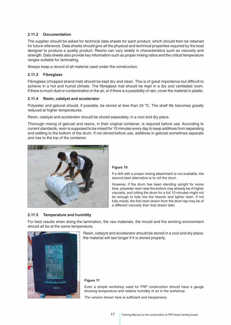
Thorough mixing of gelcoat and resins, in their original container, is required before use. According tocurrent standards, resin is supposed to be mixed for 10 minutes every day to keep additives from separatingand settling to the bottom of the drum. If not stirred before use, additives in gelcoat sometimes separateand rise to the top of the container.
Figure 10
If a drill with a proper mixing attachment is not available, thesecond best alternative is to roll the drum.
However, if the drum has been standing upright for sometime, polyester resin near the bottom may already be of higherviscosity, and rolling the drum for a full 10 minutes might notbe enough to fully mix the heavier and lighter resin. If notfully mixed, the first resin drawn from the drum tap may be ofa different viscosity than that drawn later.
2.11.5 Temperature and humidity
For best results when doing the lamination, the raw materials, the mould and the working environmentshould all be at the same temperature.
Resin, catalyst and accelerator should be stored in a cool and dry place;the material will last longer if it is stored properly.
Figure 11
Even a simple workshop used for FRP construction should have a gaugeshowing temperature and relative humidity of air in the workshop.
The version shown here is sufficient and inexpensive.

18 Training Manual on the construction of FRP beach landing boats
If the temperature is much above 30 ºC, for example 37 ºC, geltime will be shortened. If the temperatureis considerably lower than 30 ºC, risk of insufficient curing is high. Lower temperatures and high humiditycan also cause “aligatoring” (wrinkling) of the gelcoat.
If air humidity rises to above 80 percent, the binder in the CSM will absorb moisture and the reinforcement(CSM) will get “wet”, i.e. lose its strength.
A common solution to many of these problems is for lamination work to be done in the morning before thesun gets too hot or the humidity rises.
3 - WORKSHOP FACILITIES
The two main important things with FRP boat building is the workshop and the quality.
In the peak of summer in tropical countries, ambient temperatures may exceed 35° C. It is therefore veryimportant that the premises are shaded from the sun and wind, dry and adequately ventilated to removestyrene fumes and dust from the moulds and laminating area. FRP materials must be stored in conditionsas dark and cold as possible to ensure maximum shelf-life.
Figure 12
It is very important to protect the work area andFRP materials from the sun, wind and rain.
Similar care is important for storage of the rawmaterials.
If a workshop like the one shown at left is notpossible, a temporary shelter should beconstructed using, for instance, canvas.
Very important…
It is very important to have a reliable shelterto work in that protects the job from rain,sun, wind, dust (elements that cancontaminate the laminate and retard thecure), moisture, heat and humidity (asmuch as possible).
A concrete floor is a good investment.
Keep the work area tidy!Don’t get into sloppy habits!
Figure 13

19 Training Manual on the construction of FRP beach landing boats
4 - TOOLS TO BE USED
Figure 14
This photo shows examples of some tools used when building anFRP fishing boat.
The brushes are best for applying gelcoat, but can also be used forgetting polyester resin into tight corners and onto small details.
Resin rollers of different sizes can be used. They should be made ofmaterials that will not be damaged by solvents.
A variety of compacting rollers are employed for different applications.
The rollers must be used firmly but not too hard. Compacting muststop as soon as the resin starts to gel. Continued used of rollers atthis time will only create air bubbles, not remove them.
Figure 15
The 60- (or courser) grit sandpaper is used to sandthe laminate first. The 80- and 120-grit sandpapersare used for medium finish work.
Wet sandpaper should be in these grits: 240, 400, 600,800, 1 000 and 1 200. These are intended for finishwork on the mould and on the gelcoat of the hull.
Figure 16
Funnels are handy for pouring polyester safely intosmaller containers when larger buckets are not beingused.
Transparent measuring containers of several sizes areuseful for measuring polyester and gelcoat.
A weight scale is an alternative for measuring smallamounts of gelcoat and polyester, and also forweighing fibreglass.

20 Training Manual on the construction of FRP beach landing boats
Figure 17
A variety of syringes can be used for correctly measuringvery small amounts of hardener.
A typical cap from a soda bottle can usually hold around5 ml of hardener.
Figure 18
Two sizes of masking tape are used for a variety of tasks.For example, it can be used to keep two different coloursof gelcoat separate on the hull during construction or whenisolating an area for repair operations. The tape is alsohandy for securing a plastic cover used for protectionagainst dust or rain.
Scrapers with handles are used for spreading putty.
The wider, soft steel trowels typically used for bodyworkon cars can also work well for this purpose.
Figure 19
A regular knife or utility-type knife with extra blades can beused for cutting dry reinforcement (CSM) or “soft” laminatefrom edges.
Screw drivers are needed for mounting stainless steelcleats and drain plugs.
CSM can also be cut with scissors or torn gently by hand.
A wood chisel is handy for removing bumps and curedstrands of fibreglass.
Figure 20
Rubber mallets are useful for careful tapping of moulds tohelp with demoulding.
A regular hammer is more useful for driving in woodenwedges inserted around the edge of the mould.
Combination wrenches are used for mounting bolts andnuts on the fender and with cleats, eye bolts and u-bolts.
A spanner (adjustable wrench) is also handy for holdingbolts and nuts during tightening.
21 Training Manual on the construction of FRP beach landing boats
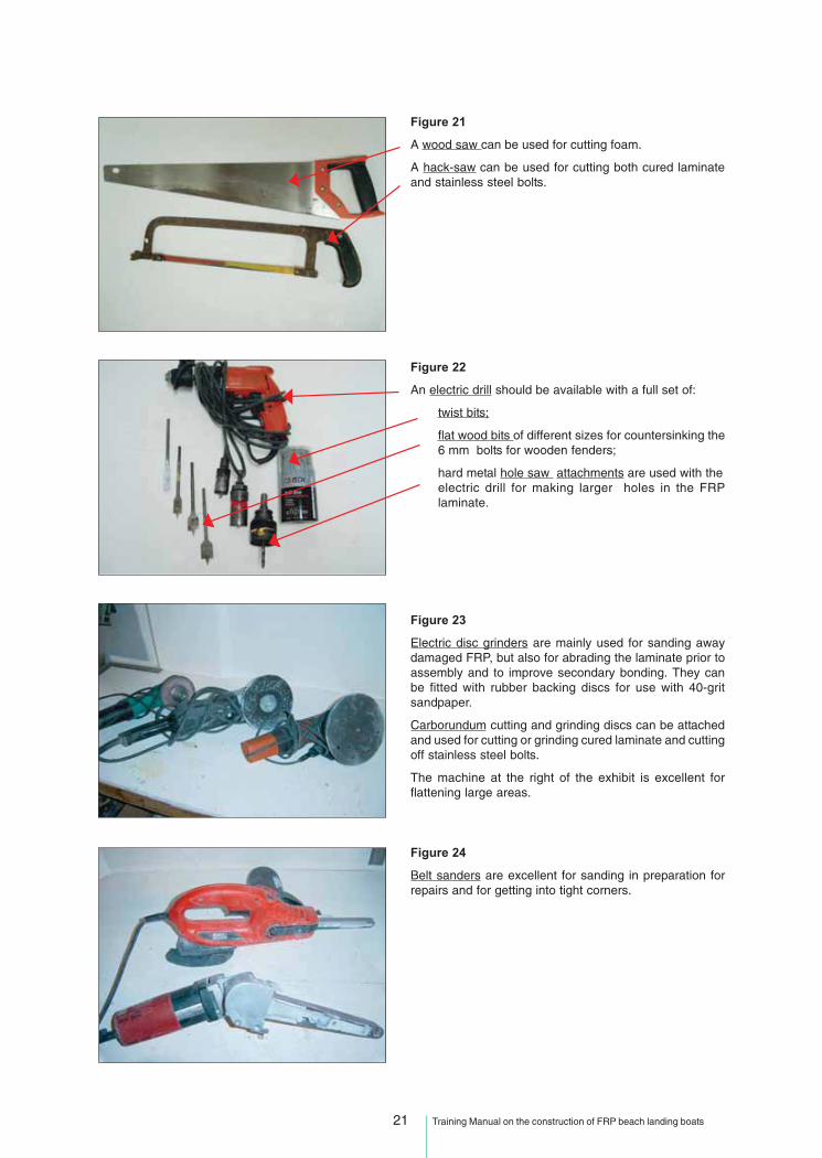
Figure 21
A wood saw can be used for cutting foam.
A hack-saw can be used for cutting both cured laminateand stainless steel bolts.
Figure 22
An electric drill should be available with a full set of:
twist bits;
flat wood bits of different sizes for countersinking the6 mm bolts for wooden fenders;
hard metal hole saw attachments are used with theelectric drill for making larger holes in the FRPlaminate.
Figure 23
Electric disc grinders are mainly used for sanding awaydamaged FRP, but also for abrading the laminate prior toassembly and to improve secondary bonding. They canbe fitted with rubber backing discs for use with 40-gritsandpaper.
Carborundum cutting and grinding discs can be attachedand used for cutting or grinding cured laminate and cuttingoff stainless steel bolts.
The machine at the right of the exhibit is excellent forflattening large areas.
Figure 24
Belt sanders are excellent for sanding in preparation forrepairs and for getting into tight corners.

22 Training Manual on the construction of FRP beach landing boats
Figure 25
A power saw with a laminated hard metal blade, like the oneshown here, is useful for cutting both wood and FRP laminate.
5 - BASIC LAMINATE BUILDING
5.1 PREPARING THE MOULD
Prepare the mould by either applying release wax and polishing, or applying mould release agent, asdescribed in Figure 26. The next step in building an FRP boat is the preparation and application of gelcoat.After the gelcoat has been mixed with the right amount of hardener, as stated on the data sheet, it isimportant that the right thickness be applied either by rolling, brushing or spraying. An ideal total thicknessof this layer of gelcoat is between 0.4 and 0.8 mm. Gelcoat thickness can be measured using a simple“wet film gauge” obtained from the gelcoat supplier. A gelcoat thickness gauge can also be made froma piece of metal. For practical reference, since a generous layer of gelcoat applied by brush is around0.25 to 0.3 mm, two layers should be sufficient.
Figure 26
Brushing gelcoat on to the black surface of the mould is shownin the photo.
Figure 27
The photo shows the use of a gelcoat thickness or wet filmgauge.

23 Training Manual on the construction of FRP beach landing boats
This initial layer of gelcoat must be properly cured before lamination can start. It is best to wait 3–4 hoursfor curing to be complete. If laminating starts sooner than one and a half hours after gelcoating, there isa danger that the polyester will soften up the gelcoat, causing it to wrinkle. This effect is called “aligatoring”.
To achieve a good primary bond between the gelcoat and polyester resin, the lamination process shouldbe started as soon as possible after four hours and definitely within 24 hours of gelcoat application. Thisrule also applies for the “open time” (working time) of the polyester to ensure a good primary bond betweenlaminate layers. (Primary bond is discussed in more detail in Part IV – Manufacturing defects and repairs).Precautions should be taken against contamination of the gelcoat surface. If a mould with fresh gelcoat isleft overnight in an open shed, the mould should be covered with light plastic. This is especially importantin wet or windy weather or other conditions that might result in gelcoat contamination.
All required materials should be prepared before starting to laminate over gelcoat. The fibreglass resinshould be thoroughly stirred and at room temperature before hardener is added and mixed. Once resin ismixed with hardener, all steps needed to build a layer of laminate must be completed quickly as themixture can be worked for only 10–15 minutes. Suppliers should provide a technical paper detailing howlong polyester can be worked at a certain temperature with a specific amount of hardener.
Only mix as much polyester and hardener as can be applied to the fibreglass mat in the time available.A small amount of polyester mixed in large container, as shown in Figure 28, is less likely to start gellingearly than if the same amount of polyester is mixed in a small container. The difference in gel time iscaused by increased exotherm buildup. This problem can also occur if laminates are too thick.
5.2 MIXING POLYESTER RESIN
Follow the initial steps set out in the section on “Material Description and Handling”, make sure that youuse the correct amount of hardener for a good cure.
Figure 28
A handy tool for measuring hardener can be made byattaching a piece of steel wire to a bottle cap. A syringecan be used to measure the exact amount contained inthe bottle cap.
A typical cap from a soda bottle will hold 5 ml of hardener.To measure 1% of hardener by volume, one capful issufficient for 500 ml (1/2 litre) of polyester.
A coat of polyester resin should always be applied before laying on the fibreglassmat. The metal roller is effective for working out any air bubbles and for compactingthe resin and fibreglass layers together.
In case there is no scale for measuring polyester resin, one may assume that one kilogram equals almostone litre. For either measure, there will be no significant loss of quality when working with these materialson a sturdy structure such as the IND-30 boat.
5.3 THE FIRST LAYER, OR BACKUP LAYER
The first layer (backup layer) consists of resin and a 300 g mat. There should be no bumps or contaminationon the cured gelcoat prior to starting the lamination. It is vital that all air bubbles are carefully worked outand the first layer is allowed to cure for 4 to 6 hours, maybe even overnight, before the next layer is added.

24 Training Manual on the construction of FRP beach landing boats
For the backup layer, it is especially important that the fibreglass mat be torn (Figure 29) rather than cut.For this layer, the pieces of mat should be placed edge to edge with no overlap. This technique providesa smooth transition between the skin coat and subsequent layers, and does not interfere with the structureof the boat. Since the skin coat is not a structural layer, joining fibreglass pieces together in this way doesnot interfere with the overall strength of the final product.
Iso-polyester should always be used in the backup layer to help waterproofing the hull and avoid osmosis.
Figure 29
This photo shows how the first layer (backup layer) offibreglass is applied.
The gelcoat is completely covered with a generouslayer of polyester to make sure no air is trapped closeto it.
Fibreglass mat with torn edges is then applied carefullyover the polyester layer and rolled thoroughly.
Figure 30
Proper use of compacting rollers is very important. Theyare used to ease fibreglass mat into the underlyingpolyester and remove all air trapped between the two. Thisprocess must be completed before the polyester beginsto set up and cure.
This boatbuilder is using a small compacting roller to pushfibreglass into a tight groove and ensure that any trappedair is removed.
Fibreglass to Polyester Resin Volume:
33.3% 66.6%
1 kgFibreglass
1 kg polyester
3 kg Laminate
Corner
Flat Surface
Overlaping Fibreglass in Structural Layers(Overlap 5 cm or 2 inches minimum)
Figure 31
Shows the right amount of fibreglass (CSM) andpolyester to use in a CSM laminate, and how tostagger/overlap the pieces of fibreglass mat in astructural layer.

25 Training Manual on the construction of FRP beach landing boats
5.4 INSPECTIONS
Continuous visual inspection is very important for quality control. A close watch must be kept to detectsurface contamination and trapped air. If the fibreglass is too wet, the laminate will turn white. If theexotherm builds up too quickly, the colour of the laminate will change and appear aerated/foamy. If toomuch polyester has been used, wet puddles will occur. The boatbuilder is usually the only person who candetect and correct such faults, and when the next layer of laminate is in place, the faults will be invisible.If such faults are not corrected immediately, the finished new boat will already have weaknesses, minoror major.
5.5 LAMINATION OR MOULDING
For construction of the 8-m IND-30 BLC, both CSM and woven roving (WR) are being used. A mainconcern when laminating is to assemble each layer at the proper time interval. The laminate should beallowed to cool down after the curing process (exotherm) before starting on the next two layers. The topicof primary and secondary bonding and preparation of the surface to be laminated are set out in moredetail in Part IV, Manufacturing defects and repairs.
6 - QUALITY
Quality is very important. Because the FRP boats are hand-made, the quality will always vary. Since youare the boatbuilding expert, you will probably be blamed if the quality suffers whenever a customer insistson cutting expenses.
FRP boats should comply with national safety legislation. For guidance, see also Annex 4 of this manualand the Safety guide for small fishing boats (BOBP/REP/112, 2009).
High quality starts with good design and drawings, and is greatly helped by being well organized.
The IND 30 is designed by an experienced professional naval architect who, as part of his training, hasstudied all aspects of boat design. It is for these reasons that the drawings should be understood and theboat built according to the drawings.
See the drawings for the IND-30 in Annex 3.
Air, moisture, dust and dirt in the laminate all contribute to quality problems with the boats.
Osmosis is one problem to be avoided as much as possible; cleanliness, thoroughness, correct materialstorage and choice will all help.
FRP is almost waterproof but not totally, and water will work its way through the gelcoat and cause osmosis,collecting in any voids or pieces of dust and dirt behind the gelcoat, and will begin to blister and rot thelaminate.
FRP laminates with osmosis can lose up to 30 percent of their strength from osmosis.
Figure 32
This photo shows the results of poor quality control.
Large pockets of air have been left in the first fibreglass layer ontop of the gelcoat.
A good boatbuilder is a careful boatbuilder,and the quality of the work can be judged
years after the job has been done.

26 Training Manual on the construction of FRP beach landing boats
Four practices to avoid
Figure 33
Examples and consequences of bad practice:
• Avoid standing barefoot directly on the laminate. This is verydangerous to your body as well as to the construction. Sweat, talcand dirt will weaken the strength of the bond between the layers.
• Avoid wetting through the CSM mat, as mentioned above.
• While laminating and curing, never expose any part of the FRPboat to the sun.
AVOID BAD PRACTICES!
7 - HEALTH AND SAFETY ISSUES
Personal and environmental safety when working with FRP
7.1 PERSONAL SAFETY
7.1.1 Eye safety
In all industrial environments, protection is needed to prevent objects or chemicals from getting into workers’eyes. When working with FRP, care is needed to avoid both chemical hazards, including anything fromeye irritation to severe corrosion and physical hazards such as irritation from airborne particles.
For example, the catalyst/hardener (methyl ethyl ketone peroxide, or MEKP) is a severely corrosiveliquid. Grinders produce many dangerous airborne particles. In both cases, eye protection, mainly in theform of goggles, should be worn when working with FRP materials.
Figure 34
At left are examples of goggles for effective eye protection,ear protectors for hearing safety, and a dust mask for lungprotection during grinding.
1. The practice of laying dry glassfibre into a mould and wetting through is unaccept-able. You must wet the job first to get the fibres wet out correctly.
2. The practice of laying all layers in one go is unacceptable due to problems of exotherm(laminate gets hot and turns white or purple, loses strength and pulls and shrinks thepart in that area).
3. The practice of using unpromoted resin (pure resin without accelerator) as a solventfor storing brushes is dangerous. You will be using a brush with resin in it that will notcure properly.
4. Do not use less than 0.8% catalyst (8 ml to 1 kg polyester) or less than 1% accelerator,or the part may not cure properly. Check with your resin supplier.
27 Training Manual on the construction of FRP beach landing boats
7.1.2 Hearing safety
Being exposed to loud sounds, constantly or even periodically, can eventually lead to permanent hearingloss. Ear protection should always be used whenever a power tool, such as a grinder or other noisymachinery, is in operation. For safety reasons, extra attention is necessary when communicating with andlocating co-workers when ear protection is used; otherwise, it will not always be possible to hear a warning.
7.1.3 Breathing safety
Lungs are one of the most obvious and important organs to protect in a boatbuilding plant. Most boatyardshave mechanical ventilation to keep the levels of volatiles, or hazardous fumes, and dust below anacceptable level. Even if fans/extractors are operating, a suitable respirator should be worn when there isdirect exposure to hazards such as styrene fumes and fibreglass dust. There may be no immediateindication that exposure to such hazards is having an effect, but in the long-term, fibreglass dust willcollect in the lungs, causing breathing problems and eventually result in lung collapse. The styrene fumesfrom polyester can cause nerve problems and possible brain damage, while the isocyanides released bythe curing of polyurethane are poisonous and the amines released during the curing of epoxy have beenlinked to cancer.
When working with volatile fumes in a closed area with poor or no ventilation, such as inside a boat,respirators with an external source of fresh air must be worn for protection. Failure to use such protectioncan result in chemical lung inflammation.
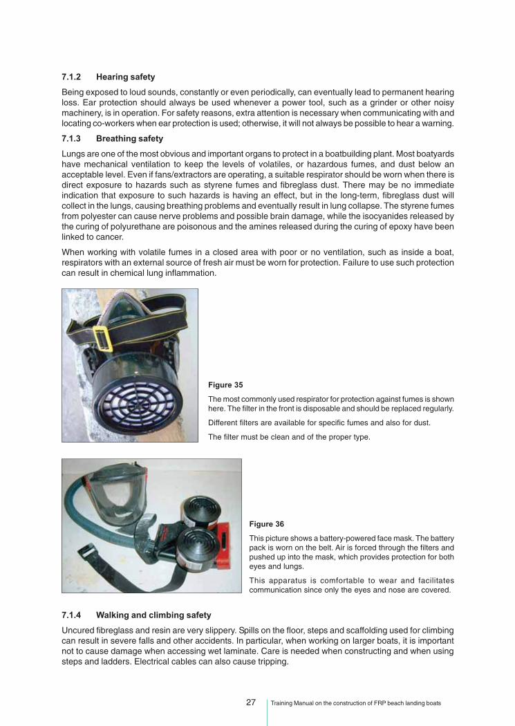
Figure 35
The most commonly used respirator for protection against fumes is shownhere. The filter in the front is disposable and should be replaced regularly.
Different filters are available for specific fumes and also for dust.
The filter must be clean and of the proper type.
7.1.4 Walking and climbing safety
Uncured fibreglass and resin are very slippery. Spills on the floor, steps and scaffolding used for climbingcan result in severe falls and other accidents. In particular, when working on larger boats, it is importantnot to cause damage when accessing wet laminate. Care is needed when constructing and when usingsteps and ladders. Electrical cables can also cause tripping.
Figure 36
This picture shows a battery-powered face mask. The batterypack is worn on the belt. Air is forced through the filters andpushed up into the mask, which provides protection for botheyes and lungs.
This apparatus is comfortable to wear and facilitatescommunication since only the eyes and nose are covered.
28 Training Manual on the construction of FRP beach landing boats
7.1.5 Hand and finger safety
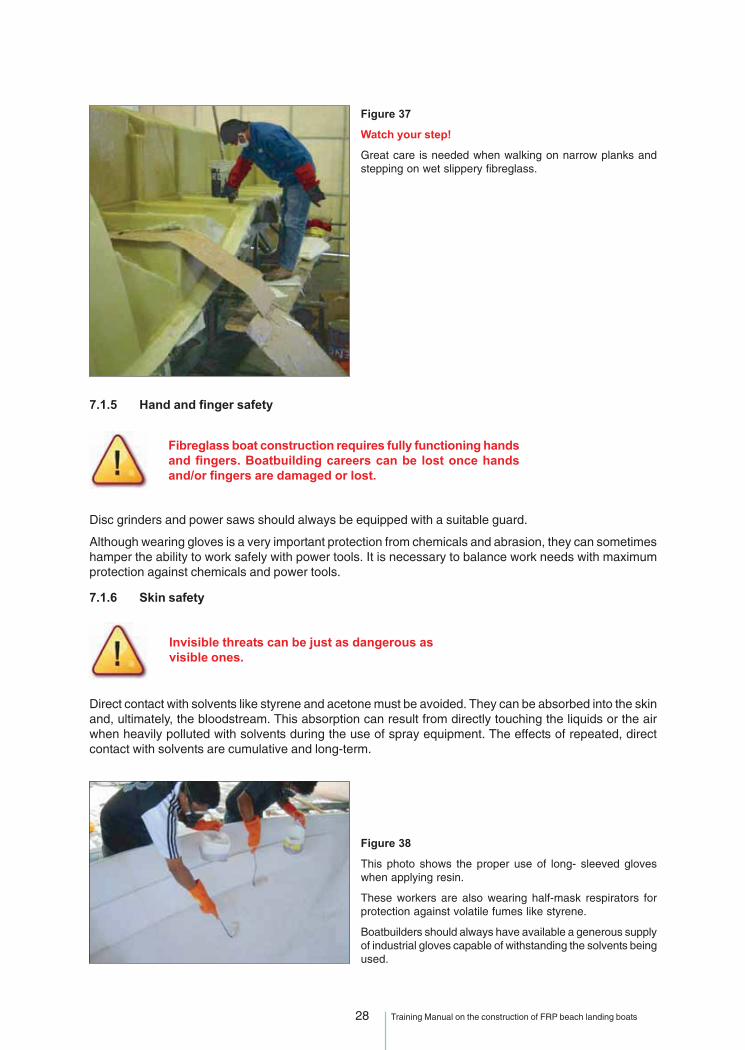
Figure 37
Watch your step!
Great care is needed when walking on narrow planks andstepping on wet slippery fibreglass.
Disc grinders and power saws should always be equipped with a suitable guard.
Although wearing gloves is a very important protection from chemicals and abrasion, they can sometimeshamper the ability to work safely with power tools. It is necessary to balance work needs with maximumprotection against chemicals and power tools.
7.1.6 Skin safety
Fibreglass boat construction requires fully functioning handsand fingers. Boatbuilding careers can be lost once handsand/or fingers are damaged or lost.
Direct contact with solvents like styrene and acetone must be avoided. They can be absorbed into the skinand, ultimately, the bloodstream. This absorption can result from directly touching the liquids or the airwhen heavily polluted with solvents during the use of spray equipment. The effects of repeated, directcontact with solvents are cumulative and long-term.
Invisible threats can be just as dangerous asvisible ones.
Figure 38
This photo shows the proper use of long- sleeved gloveswhen applying resin.
These workers are also wearing half-mask respirators forprotection against volatile fumes like styrene.
Boatbuilders should always have available a generous supplyof industrial gloves capable of withstanding the solvents beingused.

29 Training Manual on the construction of FRP beach landing boats
Most materials used for FRP construction are highly volatile and flammable. Everyone in the workplacemust take responsibility for eliminating fire hazards. The combined effect of smoking cigarettes and inhalingvolatile fumes greatly increases health risks. At least one fire extinguisher should always be available in aboatyard.
Electrical appliances and power tools must be used with care. Electrical cables represent major risks,including poor wire condition and loose contacts that can cause explosions or start fires. Air-poweredtools are safer.
Any leakage or spillage of catalyst can pose a significant fire hazard whether spraying or hand laminating.
When too much catalyst is used or when too much time is spent on some laminating details, resin maybegin to set up in the bucket (early “kick off”). In such circumstances, the exotherm can quickly build upcausing a fire unless the bucket is removed to a safe place and water is poured on top of the resin.
Abnormal exotherm buildup can also occur when saturated wet fibreglass is discarded into a wastecontainer. Rags, wet with solvent, should not be discarded into the same container.
Mixing accelerator and catalyst (promoter and initiator) together causes explosions.
7.2 WORKSHOP SAFETY
7.2.1 Controlling dust and fumes
When sanding, the most effective way of controlling dust is at the source. An extraction fan/dust collectorwith a large hose diameter, or a vacuum cleaner (preferably a “HEPA VAC”) connected to a hose attachmenton the grinder itself, is required.
Because it is very difficult to eliminate all dust at the source, a combination of approaches can be usefulin maintaining good working environment in a workshop where several operations are being carried out atthe same time.
In a boatbuilding plant, the most effective approach is to carry out as much of the sanding and grinding asis practically possible in a separate room.
To control fumes, there should always be some sort of air extraction and ventilation in the painting, gelcoator laminating work areas. This arrangement minimizes the part of the boatbuilding plant where respiratorsare required.
7.1.7 Fire hazard safety
Smoking and open fire should not bepermitted in a boatbuilding plant orboatyard.
Figure 39
The man on the left is spraying gelcoat and has arespirator with an external air supply. This is good practice.The man on the right is preparing CSM and wearing norespirator, even though the air is heavily loaded withstyrene. This is bad practice.
In addition, since the activities are carried out so closelytogether, the gelcoat overspray will contaminate thefibreglass on the cutting board. This could reduce thequality and strength of the resulting laminate.

30 Training Manual on the construction of FRP beach landing boats
7.2.2 Controlling fire hazards
7.2.3 Reducing waste and disposal of material
Plans and good routines for waste disposal are necessary to minimize fire hazards and pollution. Localauthorities have regulations on how to handle the hazardous waste. Money can often be saved by separatinghazardous and non-hazardous waste.
Careful management of raw materials to avoid wastage also saves money
Note that discarded chemicals, hardened resins andfoams all have short- and/or long-termnegative effects on the environment.
7.2.4 Raw material storage
Ideally, all raw materials should be stored in separate rooms to retain quality prior to use and for safetyreasons. In particular, it is important to keep the catalyst in a separate room from the polyester and gelcoatin order to reduce the potential hazard of fire.
7.2.5 Documentation
All technical data sheets provided by the supplier for each material purchased should include everythingneeded to handle the chemical safely. It is recommended that all technical data sheets be collected ina binder, kept in a safe place and be available to all personnel who may potentially be exposed to thesechemicals.
Figure 40
One example of very dangerous conditions in a workshop.
The electric grinder is shown sitting on top of a full barrel ofpolyester, which is highly flammable!
The shop manager has overall responsibility for maintaininga safe working environment and reducing the risk of fire!

31 Training Manual on the construction of FRP beach landing boats
PART II
BUILDING OF PLUGS AND MOULDS
32 Training Manual on the construction of FRP beach landing boats
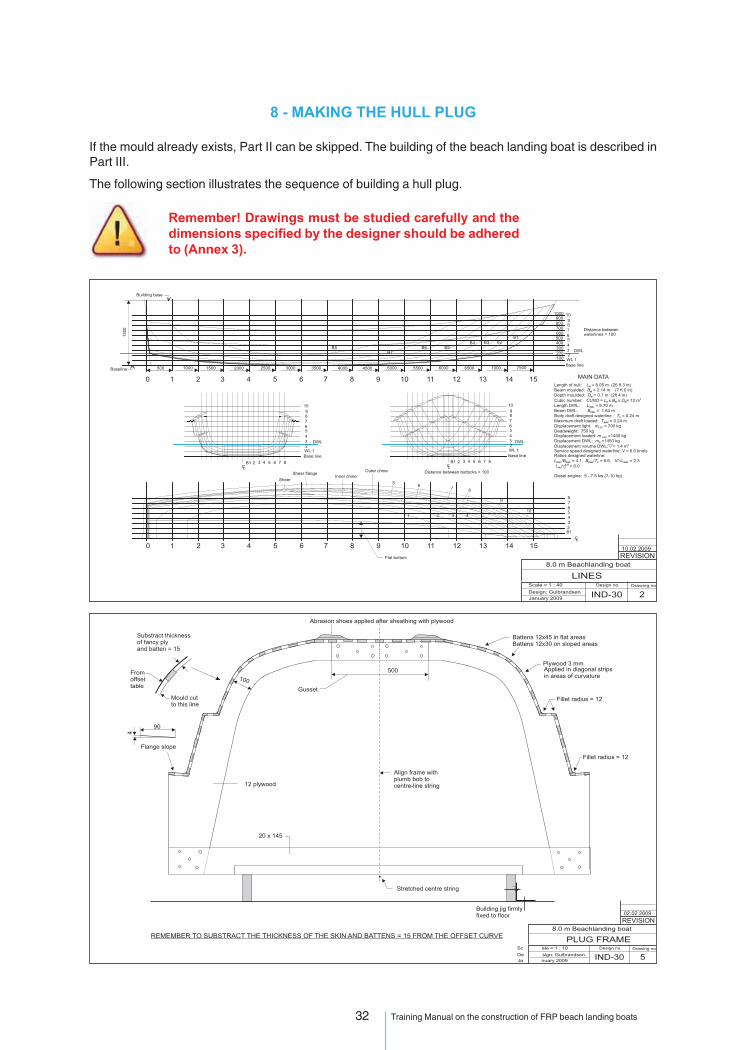
8 - MAKING THE HULL PLUG
If the mould already exists, Part II can be skipped. The building of the beach landing boat is described inPart III.
The following section illustrates the sequence of building a hull plug.
Remember! Drawings must be studied carefully and thedimensions specified by the designer should be adheredto (Annex 3).

33 Training Manual on the construction of FRP beach landing boats
34 Training Manual on the construction of FRP beach landing boats
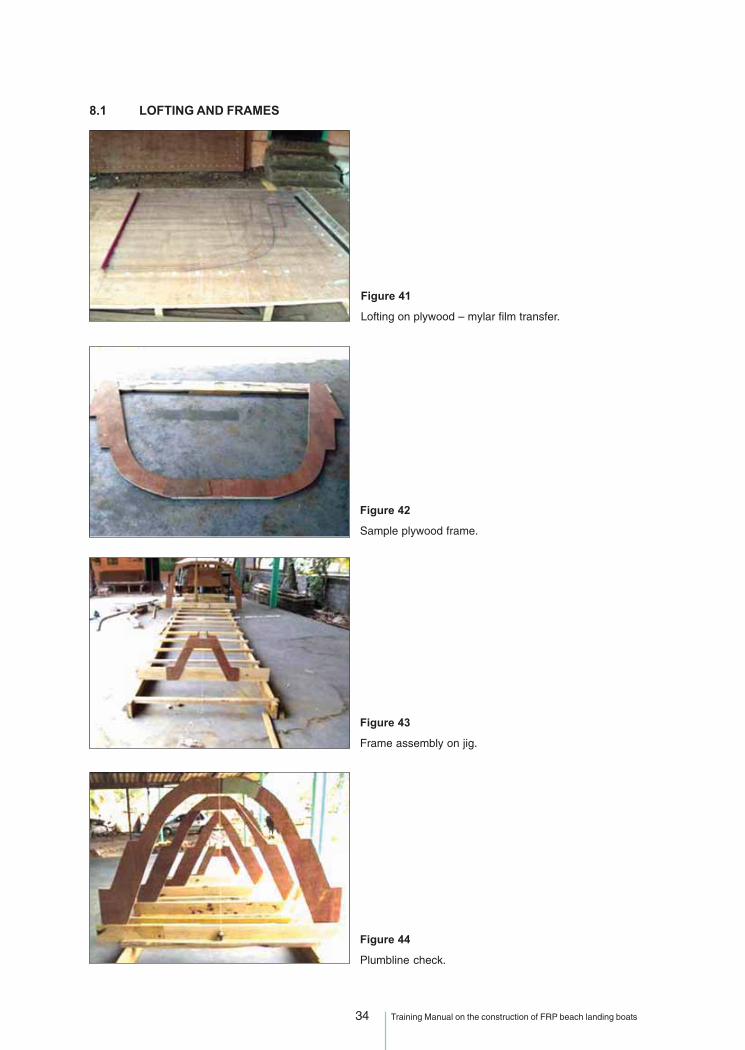
Figure 41
Lofting on plywood – mylar film transfer.
8.1 LOFTING AND FRAMES
Figure 42
Sample plywood frame.
Figure 43
Frame assembly on jig.
Figure 44
Plumbline check.

35 Training Manual on the construction of FRP beach landing boats
Figure 45
Frame assembly.
Figure 46
Applying veneer ply skin.
8.2 HULL SKIN
Figure 47
Topside skin.
Figure 48
Diagonal strips for a curved surface.

36 Training Manual on the construction of FRP beach landing boats
Figure 49
Skin complete.
Figure 52
Hull plug ready for painting.
Figure 50
Preliminary fairing.
Figure 51
Applying autograde putty.

37 Training Manual on the construction of FRP beach landing boats
Figure 53
Spray painting – first coat.
A two-component paint should be used that will resist thesolvents in the tooling gelcoat that will be applied.
Figure 54
Spray painting and rubbing down.
Figure 55
Finished plug.
THE PLUG FINISH WILL DETERMINETHE MOULD FINISH

38 Training Manual on the construction of FRP beach landing boats
9 - MAKING THE MOULD
Useful tips when making a mould are:
• Use large flanges for stability.
• Use plenty of framing to add stability, either plywood on edge or FRP top-hat.
• Restrict all secondary bonding on the outside of the mould to light laminates in order to avoidshrinkage and pulling the mould,
• Ensure that mould thickness is 6 mm thick for a boat up to 3 m in length, then add 2-mm thicknessfor each metre of length.
• Use a proper tooling gelcoat that is light-coloured to reduce the heat of the mould. Do not lay up themould too quickly.
• For a better result, do one lay up in the morning and one lay up in the afternoon until the requiredthickness is obtained. Thickness can be obtained with a core material.
• Avoid print through by using no roving or core material closer than 6 mm from the gelcoat.
Figure 56
The buffing compound used to polish the mould after releasefrom the plug as a step after wet sanding and before waxing,or to polish the plug surface.
Read the instructions on the can.
Figure 58
Gelcoat on transom.
Figure 57
Flange on transom.

39 Training Manual on the construction of FRP beach landing boats
Figure 59
Transom lay-up completed.
Figure 60
Centre flange on hull plug (the purpose of which is to make asplit mould).
Figure 61
Gelcoat on starboard half.
Figure 62
Mould lay-up.

40 Training Manual on the construction of FRP beach landing boats
Figure 63
Mould lay-up.
Figure 64
Mould framework. The shape of the frame is for tilting of themould (See Figure 80) .
Figure 65
Mould framework.Figure 66
Rubbing down with water emery.
Figure 67
The completed split mould (withoutthe transom).
41 Training Manual on the construction of FRP beach landing boats
PART III
BUILDING AN FRP BEACH LANDING BOAT

42 Training Manual on the construction of FRP beach landing boats
10 - BUILDING AN FRP BEACH LANDING BOAT
10.1 PREPARATION
The following is a practical guide to building an FRP boat, using an IND 30 8-m BLC as an example.
A beach landing boat operating from surf-beaten beaches is subject to a much harsher environment thana boat operating from a creek or harbour. It is subject to tremendous impact forces when crossing breakersand landing on the beach. In addition to impact, a BLC is also subject to severe abrasion when it is hauledup on to the beach each day. These operating conditions must be taken into account when deciding hulllay-up and structural arrangements.
Figure 68
Before starting, study the drawingsthoroughly to understand the details of thelay-up schedule and structural details.
Typical drawings required are given inAnnex 3.
Recommendations for determining FRP scantlings are given in Annex 4. These are the recommendedguidelines for FRP fishing boats and form Annex III of the draft FAO/ILO/IMO Safety recommendations fordecked fishing vessels of less than 12 m in length and undecked fishing vessels, which are underdevelopment.
On the IND 30 hull, we are using two layers of woven roving in the bottom, combined with CSM. The CSMbuilds thickness and the WR is good for impact strength.
On impact, the forces will be spread over a wider area if WR is used. WR layers are put as close to thelaminate surfaces as practical. If it is too close to the gelcoat, the pattern of the WR will be visible.
The structure of the IND 30 is designed by an engineer to a formula for good strength to weight. The boathas four longitudinal stiffeners, two chines and two top-hat sections in the bottom. These longitudinalsallow us to use less frames or bulkheads. The bulkheads also support the deck.
Figure 69
Finished internal structure. Note the bulkhead stiffeners tokeep the bulkheads from buckling. The gunwale will also bereinforced.
43 Training Manual on the construction of FRP beach landing boats
10.2 A TYPICAL LAMINATING SCHEDULE
A typical laminating schedule is given below for the IND-30A.
Layer Material Area to be covered
1) Gelcoat Full cover
2) Gelcoat Full cover
FIRST LAMINATION
3) 300 g/m2 (CSM) Full cover
SECOND LAMINATION
4) Fill keels with sand / resin slurry
5) 300 g/m2 (CSM) Local, to cover slurry
THIRD LAMINATION
6) 300 g/m2 (CSM) Bottom onlysurface mat (optional)
7) and 610 g/m2 (WR) Bottom only
8) and 450 g/m2 (CSM) Full cover
FOURTH LAMINATION
9) 450 g/m2 (CSM) Keel reinforcement (see drawings)
10) 450 g/m2 (CSM) Keel reinforcement (see drawings)
FIFTH LAMINATION
11) 600 g/m2 (CSM) Full cover
12) 610 g/m2 (WR) Full cover
13) 300 g/m2 (CSM) Full cover
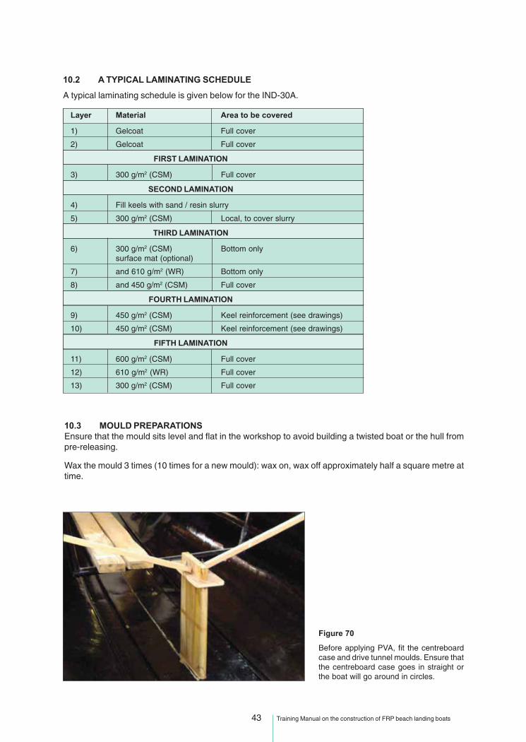
10.3 MOULD PREPARATIONSEnsure that the mould sits level and flat in the workshop to avoid building a twisted boat or the hull frompre-releasing.
Wax the mould 3 times (10 times for a new mould): wax on, wax off approximately half a square metre attime.
Figure 70
Before applying PVA, fit the centreboardcase and drive tunnel moulds. Ensure thatthe centreboard case goes in straight orthe boat will go around in circles.
44 Training Manual on the construction of FRP beach landing boats
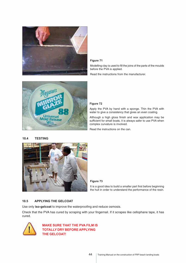
Figure 71
Modelling clay is used to fill the joins of the parts of the mouldsbefore the PVA is applied.
Read the instructions from the manufacturer.
Figure 72
Apply the PVA by hand with a sponge. Thin the PVA withwater to give a consistency that gives an even coating.
Although a high gloss finish and wax application may besufficient for small boats, it is always safer to use PVA whencomplex curvature is involved.
Read the instructions on the can.
10.4 TESTING
Figure 73
It is a good idea to build a smaller part first before beginningthe hull in order to understand the performance of the resin.
10.5 APPLYING THE GELCOAT
Use only iso-gelcoat to improve the waterproofing and reduce osmosis.
Check that the PVA has cured by scraping with your fingernail. If it scrapes like cellophane tape, it hascured.
MAKE SURE THAT THE PVA FILM ISTOTALLY DRY BEFORE APPLYINGTHE GELCOAT!
45 Training Manual on the construction of FRP beach landing boats
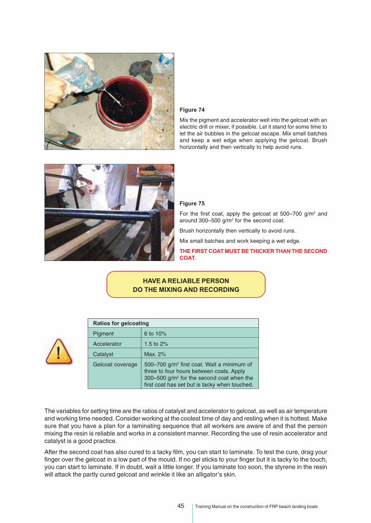
Figure 74
Mix the pigment and accelerator well into the gelcoat with anelectric drill or mixer, if possible. Let it stand for some time tolet the air bubbles in the gelcoat escape. Mix small batchesand keep a wet edge when applying the gelcoat. Brushhorizontally and then vertically to help avoid runs.
Figure 75
For the first coat, apply the gelcoat at 500–700 g/m2 andaround 300–500 g/m2 for the second coat.
Brush horizontally then vertically to avoid runs.
Mix small batches and work keeping a wet edge.
THE FIRST COAT MUST BE THICKER THAN THE SECONDCOAT.
HAVE A RELIABLE PERSONDO THE MIXING AND RECORDING
Ratios for gelcoating
Pigment 6 to 10%
Accelerator 1.5 to 2%
Catalyst Max. 2%
Gelcoat coverage 500–700 g/m2 first coat. Wait a minimum ofthree to four hours between coats. Apply300–500 g/m2 for the second coat when thefirst coat has set but is tacky when touched.
The variables for setting time are the ratios of catalyst and accelerator to gelcoat, as well as air temperatureand working time needed. Consider working at the coolest time of day and resting when it is hottest. Makesure that you have a plan for a laminating sequence that all workers are aware of and that the personmixing the resin is reliable and works in a consistent manner. Recording the use of resin accelerator andcatalyst is a good practice.
After the second coat has also cured to a tacky film, you can start to laminate. To test the cure, drag yourfinger over the gelcoat in a low part of the mould. If no gel sticks to your finger but it is tacky to the touch,you can start to laminate. If in doubt, wait a little longer. If you laminate too soon, the styrene in the resinwill attack the partly cured gelcoat and wrinkle it like an alligator’s skin.

46 Training Manual on the construction of FRP beach landing boats
10.6 MIXING OF THE RESIN
The most commonly used polyester resin is a general purpose (GP) ortho-polyester. This resin, whenmixed with 1% of MEKP catalyst, typically has a gel time of 8–15 minutes at 30 ºC.
Figure 76
If a drill with a proper mixing attachment is not available, thesecond best alternative is to roll the drum.
However, if the drum has been standing upright for sometime, polyester resin near the bottom may already be of higherviscosity and rolling the drum for a full 10 minutes might notbe enough to fully mix the heavier and lighter resin. If notfully mixed, the first resin drawn from the drum tap may be ofa different viscosity that that drawn later.
Figure 77
A variety of syringes can be used for correctly measuringvery small amounts of hardener.
A typical cap from a soda bottle can usually hold around5 ml of hardener.
Figure 78
In the case that there is no scale for measuring polyesterresin, one may assume that one kilogram equals almost onelitre. For either measure, there will be no significant loss ofquality when working with these materials on a sturdystructure such as the IND-30 boat.
Follow the initial steps set out in the section Material Description and Handling and make sure you use thecorrect amount of hardener for a good cure.
Iso-polyester with superior resistance to sea water should be used for the backup layer. Cheaperortho-polyester may be used for the main lay-up.

47 Training Manual on the construction of FRP beach landing boats
Maximum and minimum ratios
Catalyst Min. 0.8% Max. 2%
Catalyst for gelcoat Min. 1.5% Max. 2%
Accelerator Min. 1.5% Max. 2%
Keep the catalyst level above the minimum so you can easily adjust the working time as the day getshotter.
Be careful!Catalyst levels 0.8 to 2% MAX!
10.7 APPLYING THE BACKUP LAYER
The gelcoat must be backed by a layer of E 300 CSM mat. Catalyse this layer quickly to avoid alligatoring.Be careful to work out all air bubbles from this layer as this is the layer most affected by osmosis. Avoida buildup of extra resin or fibre on this layer. A uniform layer of 300 g/m2 CSM is required.
For the backup layer it is especially important that the fibreglass mat be torn (section 5.3). Always useiso-polyester for the backup layer.
A coat of polyester resin should always be applied before laying on the fibreglassmat. The metal roller is effective for working out any air bubbles and for compactingthe resin and fibreglass layers together.
Figure 79
The backup layer is a non-structural lightweight laminate.
Tilting the mould would make this job easier and release thestyrene fumes, which slow the cure of polyester.
The chine will be used to ground the edge of the deck.
10.8 SUBSEQUENT LAYERS
Follow the laminating schedule and be thorough; roll all layers with a metal roller. Continue to laminate,not leaving the open laminate for more than 24 hours.
In the tropics, be aware of weather changes. You may need to stop laminating and cover the job if it rains.
Figure 80
Tilting the mould is a good way to obtain access to all parts ofthe mould and also to avoid contamination with dirt.
The tilting mould releases the styrene, which is heavier thanair. Styrene fumes slow the cure of polyester resin. On thinlaminates or gelcoat, lower areas of the job may cure moreslowly than higher areas.
Figures 64 and 65 (see page 40) shows how the framing of amould could be constructed in order to make the titling of themould possible.

48 Training Manual on the construction of FRP beach landing boats
As mentioned earlier, it is wise to have a WR close to the surface. A surface mat can be used to help fill theweave of the roving and prevent the resin draining out of the laminate immediately before gelling. Theresin gets warm just before gelling, thins and runs. Using a filler up to 5 percent of resin weight to thickenthe resin has the same effect as a surface mat. Surface mat is the stronger alternative, as fillers tend toweaken the bond between layers.
The below chine area actually starts 50 mm above the chine to give an overlap to the topsides and addstrength. Overlap all layers a minimum of 50 mm except the backup layer, as this layer is not consideredstructural. Staggering of overlaps should ensure that there is no buildup of thickness at panel joints.
Figure 81
All corners must be reinforced and any sharp corners filletedwith roving strands after the gelcoat to prevent voids or resin-rich areas that will be brittle. Build up a double laminate atthe corner of the hull/transom and the stem.
10.9 BONDING IN STIFFENERS AND BULKHEADS
The internal structure is built before it is needed and laminated into the hull before the hull is released toguarantee that the hull shape is kept.
Figure 82
Longitudinals are in position ready to be tabbed in place, thenlaminated over. Longitudinal stiffener formers must be shapedto fit fairly over the hull laminate. Use a hacksaw and file toobtain satisfactory seating.
Use weights and resin putty to hold them in place. Laminateover the formers and on to the hull after proper surfacepreparation to ensure a good secondary bond.
Figure 83
Longitudinals are finished with a web bracket on to thetransom.
Reinforcement patches are for the rudder and towing eyeconnections.

49 Training Manual on the construction of FRP beach landing boats
Figure 87
Tabbing of the bulkheads and floors to the hull should be asspecified. Prior to bonding bulkheads and stringers, the areashould be well ground to ensure a good secondary bond.
Figure 84
Bulkheads should not fit tightly against the hull.
See Figure 85 and Annex 4, Appendix 2, section 4.4.19 forrecommended practice.
Hard spots cause stress concentration and subsequentlaminate failure caused by fatigue.
Figure 85
Apply a polyester filler fillet beforelaminating as has been done here.
Fit a foam fillet so that the frame will notprint through on the hull.
Figure 86
Bulkheads are filleted into place before laminating.
A clamp ensures the correct height of the bulkhead, which isvital for a good hull to deck bond later.
Note that the fitting of the bulkhead to the hull could havebeen better; having accurate moulds or templates for thebulkheads will help this.
HARD SPOT
BULK HEAD OR FRAME
FIBERGLASS ANGLES TOFORM CONNECTION
EXTRA PLIES OF FIBERGLASSMAT TO REINFORCE SHELL -OPTIONAL
FILLET CORES - USE CONTINUOUSSTRIP WITH INCOMPRESSIBLEBULKHEAD OR FRAME
SHELL OR DECKLAMINATE
THESE DIMENSIONSSHOULD BE MINIMUMCONSISTENT WITHSTRENGTHREQUIREMENT.2” MINIMUMRECOMMENDED

50 Training Manual on the construction of FRP beach landing boats
Figure 90
An example of a poorly designed and built framing system.
Well thought-out use of longitudinal stiffeners and transverseframing will result in a better and cheaper structure.
See Figure 91 below.
Figure 88
The bottom longitudinals are pre-moulded in one piece with1 x 450 g/m2 CSM, fitted and laminated over with 2 x 450 g/m2 CSM from each side, giving a total of 5 x 450 g/m2 on topto give best effect and 3 x 450 g/m2 on the sides. Limberholesare fitted before laminating the frame into the hull.
Stiffeners are added to the bulkhead to stop them buckling.
Figure 89
This is an example of a bad fit and should be rectified.
Figure 91
Example of well-designed framing system.

51 Training Manual on the construction of FRP beach landing boats
10.10 RELEASE
Release the hull as gently as possible. The use of many small wedges around the mould edges is betterthan a few big wedges that will stress the product locally.
PVA release agent can be dissolved if water is used to release the piece.
Use a rubber mallet if necessary.
Remember that the mould is an investment that should be treated gently.
Figure 92
The starboard half of the mould after the release.
Don’t release the part too soon!Make sure it has cured!
Avoid the risk for print through or pulls frompost-curing as polyester shrinks 2% as it cures.
24 hours at 400 C is good forpost-curing parts.
10.11 DETAILS
Plywood is an excellent structural material. If plywood frames are used instead of the specified FRPframes, be sure that they are marine-grade plywood. Seal the edges properly.
Figure 93
If you decide to use plywood instead of FRPfor the bulkheads, then keep the fibreglasslongitudinals as they are.
Keep the hull skin as designed.
See scantling tables for details.

52 Training Manual on the construction of FRP beach landing boats
Figure 94
Tunnel for a liftable propulsion system (the BOB drive).
Figure 95
Gelcoat on the centreboard slot plug.
Ensure that the centreboard slot plug goes in straight or theboat will go around in circles.
Figure 96
Mats being applied.
Figure 97
Plug being removed.
53 Training Manual on the construction of FRP beach landing boats
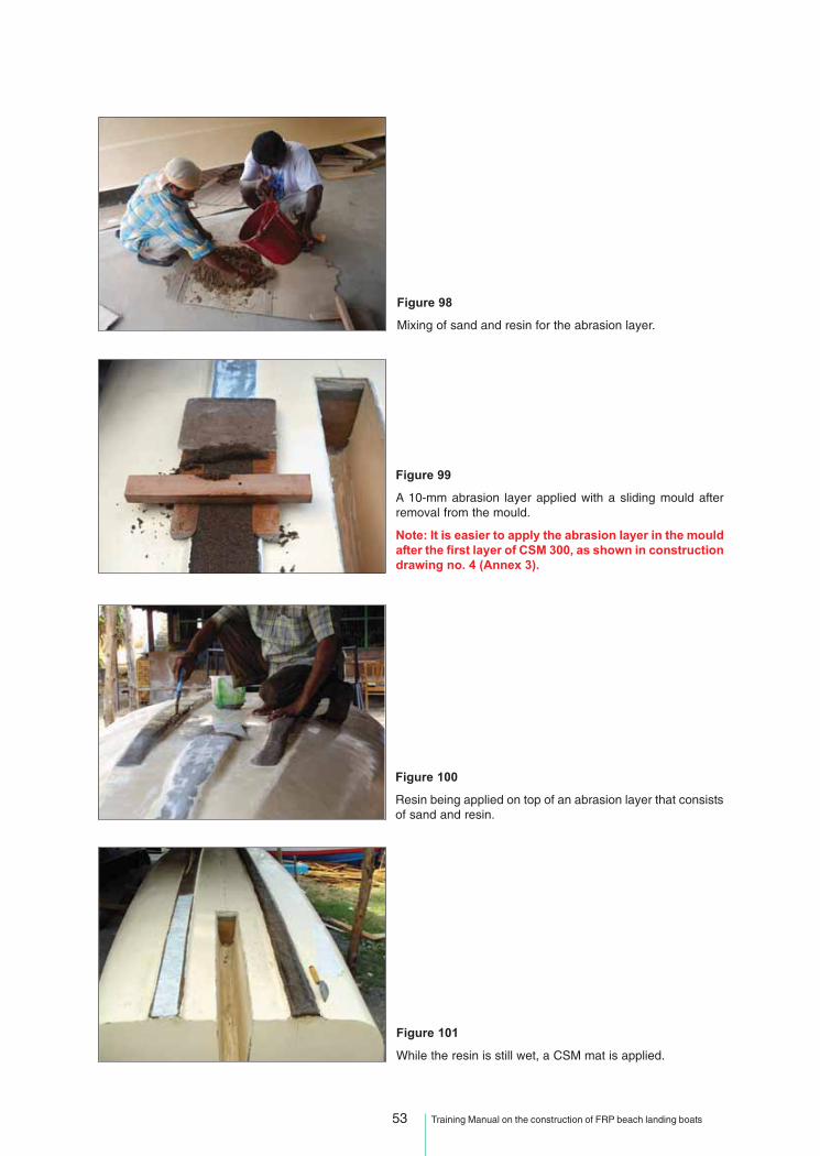
Figure 98
Mixing of sand and resin for the abrasion layer.
Figure 99
A 10-mm abrasion layer applied with a sliding mould afterremoval from the mould.
Note: It is easier to apply the abrasion layer in the mouldafter the first layer of CSM 300, as shown in constructiondrawing no. 4 (Annex 3).
Figure 100
Resin being applied on top of an abrasion layer that consistsof sand and resin.
Figure 101
While the resin is still wet, a CSM mat is applied.

54 Training Manual on the construction of FRP beach landing boats
Figure 102
Finally, the abrasion layer is covered with two layers oftopcoat.
10.12 DECK PLUG, MOULDING AND ASSEMBLY
Decks for FRP boats can be built either by using FRP-sheathed marine plywood or as an FRP mouldingsuitably stiffened. Compared with the hull moulding, an FRP deck is simpler. However, the deck to hulljoint is crucial. The deck needs to be seated on a shelf attached to the hull at sheer.
In the IND 30, the outward flange at sheer and the flat of chine provide seating of the deck. The deckassembly is of three separate pieces: the fore and aft decks at sheer level and the lower cockpit deckin between.
Deck to hull connection may be of the bolted type or by bonding to the hull with FRP angles. Prior toassembly, the seating surface and underside of the deck edge must be well ground and cleaned.The deck should be set in place over at least two layers of wet mat of E 450 g/m2 to ensurea leakproof joint.
Figure 103
Building of the deck plug (inside the hull of the first boat).
Figure 104
Hatch coamings attached to the plug.

55 Training Manual on the construction of FRP beach landing boats
Figure 105
Application of modelling clay.
Figure 106
Topcoat being applied.
Figure 107
Note the metal plates on the deck to prevent a slipperysurface.
Figure 108
Cockpit deck mould complete.

56 Training Manual on the construction of FRP beach landing boats
Figure 110
Stiffeners being attached to the underside of the deck.
Figure 109
The cockpit deck in front and the mould behind.
Some good tips for hull to deck bonding:
• Use a slurry of premixed resin and waste CSM pieces as glue. Make it thick enough to stay whereput and wet enough to bond properly.
• It is important to do a “dry fit” to check that the hull and deck fit.
• The IND 30 has deck hatches so the interior of the boat can be easily checked and worked on,which is a good feature in any boat.
• Mount any fittings that will be difficult to mount after the deck is on.
• Use fibreglass tapes to bond the deck to the hull and bulkheads wherever possible.
• Bond the deck to hull outside with 3 x 450 g/m2 CSM 120 mm wide. Stagger the layers.
• Hatches must be properly secured to the boat for safety.
Figure 111
Cockpit deck seated on chine flat. Using temporarythwarts and vertical struts to exert pressure, the deckis bonded over wet mat.

57 Training Manual on the construction of FRP beach landing boats
Figure 112
The deck edge is also connected with FRP tabbing to thehull after the seating has set.
Figure 113
Note the proper seating of the deck over the transverse bulk-head.
Figure 114
The plugs for the fore and aft decks under construction.
Figure 115
Antiskid plates on the fore deck plug.
Note the mast step.
58 Training Manual on the construction of FRP beach landing boats
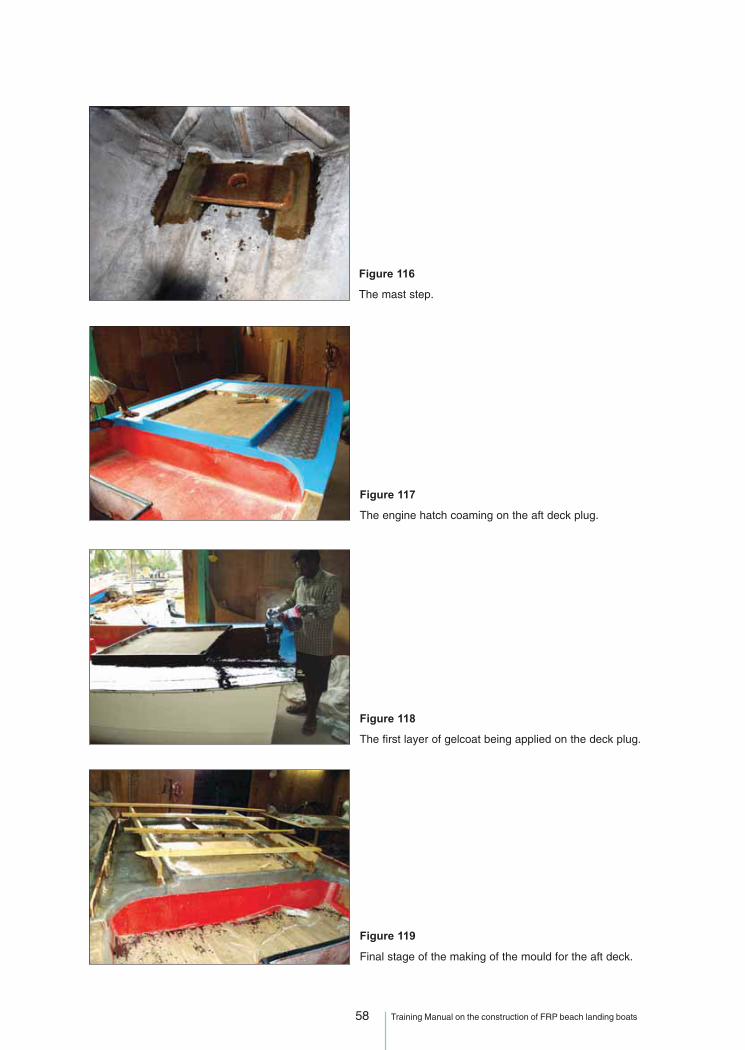
Figure 116
The mast step.
Figure 117
The engine hatch coaming on the aft deck plug.
Figure 118
The first layer of gelcoat being applied on the deck plug.
Figure 119
Final stage of the making of the mould for the aft deck.
59 Training Manual on the construction of FRP beach landing boats
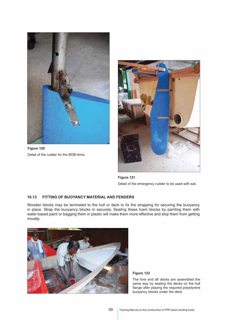
Figure 120
Detail of the rudder for the BOB-drive.
Figure 121
Detail of the emergency rudder to be used with sail.
10.13 FITTING OF BUOYANCY MATERIAL AND FENDERS
Wooden blocks may be laminated to the hull or deck to fix the strapping for securing the buoyancyin place. Strap the buoyancy blocks in securely. Sealing these foam blocks by painting them withwater-based paint or bagging them in plastic will make them more effective and stop them from gettingmouldy.
Figure 122
The fore and aft decks are assembled thesame way by seating the decks on the hullflange after placing the required polystyrenebuoyancy blocks under the deck.
60 Training Manual on the construction of FRP beach landing boats
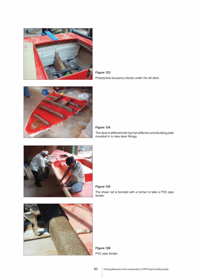
Figure 123
Polystyrene buoyancy blocks under the aft deck.
Figure 124
The deck is stiffened with top-hat stiffeners and doubling padsmoulded in to take deck fittings.
Figure 125
The sheer rail is bonded with a former to take a PVC pipefender.
Figure 126
PVC pipe fender.

61 Training Manual on the construction of FRP beach landing boats
Figure 127
PVC pipe fender being put in place
Figure 128
The finished boat.
Figure 129
The deck layout of the finished boat.
Figure 130
The BoB-drive in a lower position to the leftand in a upper position to the right.

62 Training Manual on the construction of FRP beach landing boats
Figure 131
Sea trials should be carried out together with thebuyer before the delivery of the boat.
Figure 132
Sea trials to test the stability in surf crossing.

63 Training Manual on the construction of FRP beach landing boats
PART IV
MANUFACTURING DEFECTS AND REPAIRS

64 Training Manual on the construction of FRP beach landing boats
11 - MANUFACTURING DEFECTS
Figure 133Wrinkling or “alligatoring” is a gelcoat fault caused by:
• insufficient catalyst in gelcoat.• gelcoat too thin.• backup layer applied too soon.
Figure 134
Fibre pattern is a result of:
• gelcoat too thin.• high exotherm because of bulk curing.
Figure 135
Star crazing is caused by:
• gelcoat too thick.• reverse impact.• crack pattern transferred from mould.
Figure 136
Blisters are caused by:
• moisture contamination.• rapid cure of gelcoat.
65 Training Manual on the construction of FRP beach landing boats
Hardboard or thin metal facia boardwith release agent on inner face.
Fill in with same laminateas original boat construction,if possible.
Cut back to undamaged laminate andsand to ‘V’ from front and rear.
Gelcoat
Laminate
Backup laminate. 4 layersof CSM overlapping.
Bolts through hull holding faciaplate in intimate contact withouter face. Must be clear of repairarea. Note use of washes tospread load.
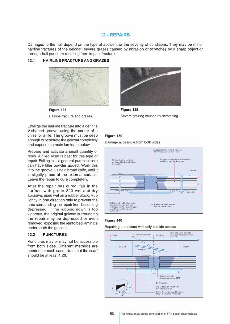
12 - REPAIRS
Damages to the hull depend on the type of accident or the severity of conditions. They may be minorhairline fractures of the gelcoat, severe grazes caused by abrasion or scratches by a sharp object orthrough-hull puncture resulting from impact fracture.
12.1 HAIRLINE FRACTURE AND GRAZES
Enlarge the hairline fracture into a definiteV-shaped groove, using the corner of achisel or a file. The groove must be deepenough to penetrate the gelcoat completelyand expose the main laminate below.
Prepare and activate a small quantity ofresin. A filled resin is best for this type ofrepair. Failing this, a general-purpose resincan have filler powder added. Work thisinto the groove, using a broad knife, until itis slightly proud of the external surface.Leave the repair to cure completely.
After the repair has cured, fair in thesurface with grade 320 wet-and-dryabrasive, used wet on a rubber block. Rublightly in one direction only to prevent thearea surrounding the repair from becomingdepressed. If the rubbing down is toovigorous, the original gelcoat surroundingthe repair may be depressed or evenremoved, exposing the reinforced laminateunderneath the gelcoat.
12.2 PUNCTURES
Punctures may or may not be accessiblefrom both sides. Different methods areneeded for each case. Note that the scarfshould be at least 1:20.
Figure 138
Severe grazing caused by scratching.
Figure 137
Hairline fracture and grazes.
Figure 139
Damage accessible from both sides
Figure 140
Repairing a puncture with only outside access
Fill in with same laminateas original boat construction,if possible.
Tube
Support
Backing laminatethree or four layers CSM.
Repair completed flush withhull exterior surface.
Cut back to undamaged laminate.Shape cut-out into a rectangle.
Backing plate
Support
Tourniquet
Tourniquet locked Wire loop

66 Training Manual on the construction of FRP beach landing boats
The following section explains the common types of damages found in beach boats and details the varioussteps in a proper repair procedure.
12.3 TYPICAL DAMAGES TO BEACH LANDING CRAFT
For everyday use, FRP generally does not need much maintenance, although this does not mean thata boat will last forever. Wear and tear and the absorption of water affect the lifespan of an FRP boat. Thechallenge is to determine whether what can be observed on the surface is merely cosmetic or constitutesmore serious structural damage.
Remember the following important points:
1. A good secondary bond is essential.
2. The area of the repair should be made slightly stronger than what it was originally.
3. Access to both sides is often needed, so you must not hesitate to tell the customer that you need tocut a new hatch in the deck to repair the hull.
When a boat is left constantly in water, the water is absorbed by the polyester laminate. Gelcoat or topcoatdoes not stop water absorption. This absorption is not visible, but the laminate can absorb 1.5 to 2 percentwater and become less stiff. After a certain number of years (5 to 15), the laminate may also react chemicallywith the water to produce hydrolysation, which is comparable to rust in steel. The speed and extent ofhydrolysation depend, on the combination of water conditions, temperature, use of the boat and how goodthe quality control was when the boat was built.
Water absorption will be slowed and the working life of the boat improved if the hull laminate below thewaterline is treated with several layers of epoxy barrier coat when the boat is new. Anti-fouling materialapplied to the hull to reduce marine growth improves fuel economy, but has no effect on water absorption.
Figure 141
In this figure, old laminate showing typical results ofhydrolysation can be seen. The polyester becomesdepolymerized and is washed out of the laminate.
The results are visible as dark spots on the surface and whitepockets deeper in the laminate.
If the gelcoat is intact, osmosis blisters might occur.
Old laminate is weaker and less stiff than new laminate, evenif damage is not visible.
Figure 142
Many boats have laminates that are just too thin.
On this boat, the laminate was 4 mm but the layers separated easilybecause of the excessive use of pigment and too much polyester withrespect to glass.
The boat would have survived had the gunwale been made tougher.
The polyester to fibreglass volume percentage should be approximately67 percent polyester to 33 percent fibreglass.
The coaming had layers of putty in between the laminate layers.
The fibres do all the work.

67 Training Manual on the construction of FRP beach landing boats
Figure 143
In addition to the iron posts working their way out, the areawhere the posts are connected to the hull is in itself a “stressriser” and many boats have failures here.
It might be easy to think that the boat breaks at this pointbecause of the pull in the steel bars, but the truth is that itbreaks because the rest of the boat is soft and this is a stiffand weak point.
In order to enable readers to understand the importance of dealing with a crack in an FRP laminate andnot underestimate the strain and stress of a loaded area, the following sections address basic structuralrepairs. The figures in the following section show that a small crack can have major consequences andproper repair work takes a long time.
Figure 144
Since the structure of the boat is somewhat “soft”, the bendingof the laminate will concentrate in “hard spots” where cracksand delaminations will develop.
All corners should be well rounded and areas with stressrisers should have additional layers of FRP to absorb anddistribute the stress and strain.
Figure 145
At the bottom of the boat, there are wear-and-tear failurescaused by abrasion, as well as cracks and delaminationsresulting from thin laminates and local stress risers, such asthe leeboard holes and poor detailing in internal structuralsupports.
Additional strips of prefabricated FRP laminates could beglued on for additional stiffness and abrasion resistance.
No shortcuts should be taken if arepair is meant to last!
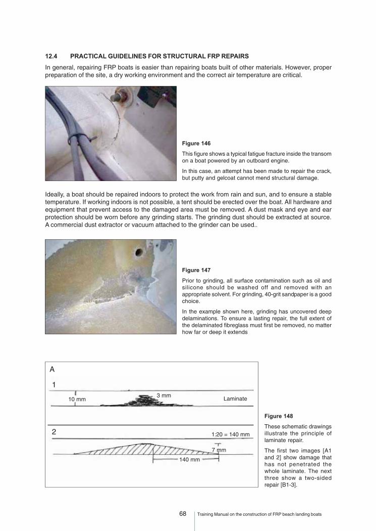
68 Training Manual on the construction of FRP beach landing boats
12.4 PRACTICAL GUIDELINES FOR STRUCTURAL FRP REPAIRS
In general, repairing FRP boats is easier than repairing boats built of other materials. However, properpreparation of the site, a dry working environment and the correct air temperature are critical.
Figure 146
This figure shows a typical fatigue fracture inside the transomon a boat powered by an outboard engine.
In this case, an attempt has been made to repair the crack,but putty and gelcoat cannot mend structural damage.
Ideally, a boat should be repaired indoors to protect the work from rain and sun, and to ensure a stabletemperature. If working indoors is not possible, a tent should be erected over the boat. All hardware andequipment that prevent access to the damaged area must be removed. A dust mask and eye and earprotection should be worn before any grinding starts. The grinding dust should be extracted at source.A commercial dust extractor or vacuum attached to the grinder can be used..
Figure 147
Prior to grinding, all surface contamination such as oil andsilicone should be washed off and removed with anappropriate solvent. For grinding, 40-grit sandpaper is a goodchoice.
In the example shown here, grinding has uncovered deepdelaminations. To ensure a lasting repair, the full extent ofthe delaminated fibreglass must first be removed, no matterhow far or deep it extends
Figure 148
These schematic drawingsillustrate the principle oflaminate repair.
The first two images [A1and 2] show damage thathas not penetrated thewhole laminate. The nextthree show a two-sidedrepair [B1-3].
A
10 mm3 mm Laminate
1:20 = 140 mm
140 mm
7 mm
1
2

69 Training Manual on the construction of FRP beach landing boats
Many manuals state that ascarf of 1:12 is sufficient forfibreglass repairs. This maybe true for unloaded areaswith thick laminates;however, for thinnerlaminates and loadedareas, the scarf should beat least 1:20.
In many cases, a scarf of1:40 or more must be usedto ensure adequateadhesion and absorption ofstresses in loaded areas.
Figure 149
When grinding has been completed, the area to be laminatedwill probably be much larger than suggested by the initialvisual inspection.
For example, in this boat, tiny cracks in the gelcoat werevisible on only one side of the engine well, but grindingrevealed that the delamination was just as deep on both sides.
A decision must be taken on what kind of materials to use for laminating once the repair area has beenidentified and prepared. The following text is a guide to making this choice.
12.5 PRIMARY BONDING
Primary bonding occurs when two surfaces are connected directly to each other, forming a chemicallyhomogenous laminate containing no weak bond line.
A fresh or “green” polyester laminate has active molecules on the surface that will bind chemically to anew laminate. Laminating on to a green laminate gives a primary bond.
Except for sanding off bumps and fibres that could cause defects and air pockets in the laminate, a freshgreen polyester laminate requires no other preparation before adding another layer.
How long the laminate surface remains active depends on a combination of the technical properties of theresin and the temperature during curing. Generally, the open time for polyester resin is 24-48 hours.
B
10 mm
1
2
3
100 mm 100 mm 1:20
1:20100 mm 100 mm
5 mm5 mm
70 Training Manual on the construction of FRP beach landing boats
When building a medium-sized boat, primary bonding can usually be achieved. When building larger FRPboats, more time is needed to complete a layer of laminate, which makes operating within open timewindows more difficult. Even so, achieving primary bonding between laminates in the main hull is crucial.In most cases, only secondary bonding will be achieved when laminating frames, stringers and bulkheadsinto larger boats.
An older polyester laminate is rarely completely cured. It will still have some reactive molecules that might,if properly sanded first, bond with the repair laminate. Wiping a sanded laminate lightly with styrene,immediately before applying a fresh polyester laminate, may also improve the bonding properties.
12.6 SECONDARY BONDING
All repair work relies on secondary bonding. Consequently, stronger or additional replacement materialwill be needed to bring the damaged area back to its original strength.
When laminating over a cured laminate, the cross-linking reaction does not occur to a significant degreeacross the bond line. Since the polymer networks are discontinuous, the bond relies mainly on the adhesivestrength of resin.
12.7 CHOOSING A RESIN FOR STRUCTURAL REPAIRS
In general, iso-polyester, vinylester or epoxy resins are preferable to general-purpose polyester resins forFRP repairs and alterations. After considering strength, cost and ease of processing for each, iso-polyesterand vinylester resins are usually recommended for most repair work.
For more critical structural repairs, laminates made with epoxy resin are generally stronger (but not stiffer).Epoxy resins are highly adhesive and have a longer shelf-life than polyester and vinylesters. Thesecharacteristics make epoxy ideal for emergency repair kits. As it requires no solvents, epoxy resin doesnot contaminate the surface of the original laminate and shows no shrinkage when curing (less tension).
Epoxy resins do not hydrolyse and this, together with good adhesion, low shrinkage and high ratio ofelongation to break, make them more liable to perform well as a primary bonded laminate. However, theyare intolerant of bad mix ratios and the setting time cannot be shortened or lengthened by altering theamount of hardener. In addition, an epoxy surface is definitely not active with styrene; therefore, anyfurther work on an epoxy boat or an epoxy repair will have to be done with epoxy. Avoid using 5 minute orvery fast epoxy for structural repairs.
A thorough cleaning and preparation of the bonding surface is very important to achieve good epoxyadhesion.
12.8 CHOOSING REINFORCEMENT FOR STRUCTURAL REPAIRS
If practical, the same reinforcement used when building the original boat should be used in the repair,especially if the part being repaired is heavily loaded and operating near its design limits. Use of lighterweight reinforcement will allow for better contact with the surface, but the importance of this featureshould be weighed against the importance of using the original reinforcement for maximum support.
Meanwhile, it should be remembered that there will be no continuous fibres attaching the old to the newlaminate, and the strength of the join will depend solely on adhesion of the new laminate to the old. Almost100 percent of stiffness can be recovered if the laminate is built up to its original thickness; however, thestrength and fatigue properties of the repaired laminate will be weaker than the original. The dimension ofthe fibre bundles is critical for the repair to perform well, because large bundles and heavy mats/fabricsobscure air and resin-rich pockets that are more likely to form at the borderline between the old and newlaminates.
It is important to take all these matters into consideration when designing the repair laminate(see Figure 150). If additional reinforcement is required to maintain the boat’s overall strength, care shouldbe taken to avoid excessive laminate buildup, since this can increase the risk of developing stressconcentrations.

71 Training Manual on the construction of FRP beach landing boats
Figure 150
In this example, the resin chosen for use was epoxy, butvinylester might also have performed well.
It should be borne in mind that this was a single-sided repairand the original polyester laminate was already showingweakness from fatigue.
The reinforcement was a mix of 290-g woven twill and 450-gdouble-bias fibreglass, chosen because of drape ability andgood performance with epoxy.
12.9 SURFACE PREPARATION
It is important not to clean a freshly sanded, porous, fibre laminate with acetone or solvent prior to lamination,unless it has been contaminated with oil or grease. If cleaning is necessary, a light grinding with cleansandpaper after washing is required, followed by sufficient time for the solvent to “air out” (evaporate).When the solvent is absorbed by the porous surface, it “contaminates” the surface laminate and candilute the new resin, preventing optimum adhesion.
When using polyester, a light styrene wipe prior to laminating is the only acceptable procedure. A smallamount of styrene will activate the surface slightly and improve adhesion. Too much styrene will weakenthe bond line.
For repairs under the waterline, fresh styrene in the new polyester laminate is also liable to trigger hydrolysis(absorption of water) at an earlier stage than in the original laminate and cause premature failure in theborderline area between the old and the new laminate.
An important issue when making repairs is to check the water content of the laminate with a moisturemeter. If the laminate contains too much water, the bonding will fail sooner than it should and the newlaminate will separate from the old one prematurely.
When it comes to the actual laminating, the same procedures as for making a new boat should befollowed, including the maintenance of high quality control standards.
Figure 151
At this stage, the laminate buildup has been completed andthe surface has been ground flat to a nice “finish”. Use ofany form of putty on structural repairs is to be carefullyavoided.
Putty has a low ratio of elongation to break, and will break upand crack much more quickly than a laminate.
Figure 152
This figure shows the finished product. Gelcoat has beenapplied, water-sanded, buffed and polished to a decent gloss.
Polyester gelcoat can be used on top of epoxy as long as theepoxy is cured properly and the epoxy surface has been fullysanded before the gelcoat is applied.
In this case, a 5-mm aluminium plate has also been attachedto distribute pressure from the bolts over a larger area.

72 Training Manual on the construction of FRP beach landing boats
Figure 153
Cross-section showing structural damage tothe frame of an FRP boat and the propermethod of repair.
1. A fracture in the outer skin has penetratedthe whole laminate and caused delaminationin the framework.
2. For the repair to be effective, the woodenframe must be cut and removed. Next, the hulllaminate must be repaired as described earlier.
3. The frame has to be ground to a scarfwherever it will be joined with other laminatesand then bonded down with putty/glue andfinished with a radius fillet.
4. All lamination work on the frame is best donewith easily drapable fabrics or 450 g/m² andlighter CSM.
Figure 154
Side view
1. This represents almost the same structuraldamage as shown in the previous figure, butviewed from the side.
2. The frame is shown cut and taken away,making the damaged laminate accessible. Inthis case, no scarf in the core of the frame isrequired as it would be on a wooden boat,because this frame is filled with foam or air,which is not a structural member.
3. The place to cut and how to cut the framewill vary depending on the damage and willhave to be estimated carefully in each case.Sometimes, when structural foam is involved,it is necessary to make a scarf in the sameway as with a wooden frame. In some cases,“stepping” the scarf may also be an alternative.Using additional extra length reinforcement,such as unidirectional fibres along the top ofthe frame, must also sometimes be consideredto add strength to the repair.
1
2
3
4
1
2
3
1:20 1:20
1:20 1:20
1:20
1:20
1:201:20
1:20
1:20
1:201:20
1:20
Frame
Lam
inate

73 Training Manual on the construction of FRP beach landing boats
Annex 1: BIBLIOGRAPHY
Anmarkrud, T. 2004. Composites repair compendium. NORBOAT/OS Boat.
Coackley, N. 1991. Fishing boat construction: 2. Building a fibreglass fishing boat. FAO FisheriesTechnical Paper 321. Rome. FAO. 84 pp. (available at ftp://ftp.fao.org/docrep/fao/003/t0530e/t0530e00.pdf)
Crystic composites handbook. No date. United Kingdom, Scott Bader Co. Ltd.
Eric Green Associates. 1999. Marine composites. Second edition. Maryland, United States ofAmerica. (parts of the book also available at www.marinecomposites.com)
FAO/ILO/IMO. 2005. Voluntary guidelines for the design, construction and equipment of smallfishing vessels.
Fibreglass Ltd. 1970. Repairing boats with fibreglass reinforced plastic. United Kingdom.
Gerr, D. 1999. The elements of boat strength: for builders, designers and owners. United States ofAmerica, McGraw-Hill.
Gulbrandsen, O. 1993. Building a liftable propulsion system for small fishing craft. The BOB drive.BOBP/MAG/14. Madras, India.
Gulbrandsen, O. 2004. Fishing boat designs: 2. V-bottom boats of planked and plywood construction.FAO Fisheries Technical Paper 134, Rev. 2. Rome. 64 pp. (available at ftp://ftp.fao.org/docrep/fao/007/y5649e/y5649e00.pdf [English]; ftp://ftp.fao.org/docrep/fao/008/y5649f/y5649f00.pdf [French];ftp://ftp.fao.org/docrep/fao/011/y5649p/ [Portuguese]; and ftp://ftp.fao.org/docrep/fao/007/y5649s/y5649s00.pdf [Spanish].)
Gulbrandsen, O. 2009. A safety guide for small fishing boats. BOBP/REP/112. Chennai, India.
International Maritime Organization (IMO). 2010. SLF 52/19/Add.1 - Safety of small fishing vessels– Consolidated text of the draft Safety recommendations for decked fishing vessels of less than12 metres in length and undecked fishing vessels. London, UK.
Kumar, A. 2007. Safety at sea aspects of small-scale fishermen of Andhra Pradesh.
Lacovara, R.R. 2001. Certified composites technician compendium. Arlington, VA, USA, AmericanComposites Manufacturers Association.
Nicholson, I. 1985. Boat data book. New York, USA, Sheridan House Inc.
Nicholson, I. 1994. Surveying small craft. New York, USA, Sheridan House Inc.
Nordic Work Group. 1984. Nordic boat standard. Det Norske Veritas. Oslo, Norway (available atwww.sigling.is/lisalib/getfile.aspx?itemid=2469 and www.sigling.is/lisalib/getfile.aspx?itemid=2468).
Rules for building and classing fiberglass reinforced plastic vessels. 1978. Houston, TX,USA, American Bureau of Shipping.
Scott, R.J. 1996. Fiberglass boat design and construction. Second ed. New Jersey, United Statesof America. The Society of Naval Architects and Marine Engineers.
Strong, A.B. 1996. Fundamentals of polymer resins for composites manufacturing. AmericanComposites Fabricators Association.
Structural Composites/Eric Green Associates. 2003. Composite boat builder certificationcompendium. American Boat and Yacht Council.
73 Training Manual on the construction of FRP beach landing boats

74 Training Manual on the construction of FRP beach landing boats
Annex 2: GLOSSARY
Backup layer or skin coat The first layer next to the gelcoat.
Bulkhead Structural interior panel set across the boat.
Accelerator (or cobalt) Reduces gel time in polyester resins.
Acetone Solvent for removal of uncured resin from equipment.
Alligatoring Wrinkling of the gelcoat.
Barcol hardness Used to measure hardness of a laminate and degree of cure.
Bidirectional Type of sewn glassfibre mat, having fibres oriented in two directions.
Binder Used to hold chopped strand mat (CSM) together until the binder isdissolved by the resin when laminating.
Bleeding The softening of the back side of a gelcoat by a resin, allowing thepigment to escape the gelcoat.
Bond strength The strength of the join between two surfaces.
Catalyst Hardener.
Chalk powder Talc.
CSM Chopped strand mat. Its weight is expressed in grams per square metre.
Cobalt See Accelerator.
g Grams.
Consolidation Rolling of glassfibre laminate to remove air.
Continuous roving Unwoven uncut glassfibre.
Core Central part of sandwich construction.
Crazing Cracking of resin from internal stress.
Cure The process of resin from gellation to full mechanical properties.
Delamination The separation of a laminate into two layers.
Drain out The leaking, sagging or puddling of resin from a laminate.
Exotherm Heat produced from the cure of resin.
Fatigue Repeated stress on a material over or near its limit of mechanicalproperties.
Fibre content (of a laminate) Weight expressed as a ratio to resin.
Fillers Aerosil, milled fibres or talc to thicken resin.
Frame Structural member set across the boat.
FRP Fibreglass reinforced plastic.
Gel Partial curing stage of resin.
Gelcoat Surface coating.
Gel time Working time of a resin.
GRP Glass reinforced plastic, same as FRP.
Humidity Air moisture content.
Inhibitor Chemical designed to increase working time of resin.
MEKP Methyl ethyl ketone peroxide – Hardener or catalyst for polyester resin.
MEK Methyl ethyl ketone – A solvent.
Milled fibres Very short lengths of glass used as a filler powder to thicken resin.
Osmosis When water creeps straight through the gelcoat and into the laminatecausing blisters and other problems.
PVA Polyvinyl acetate (wood glue).
PVA Polyvinyl alcohol (mould release agent)
Pigment Used to colour gelcoat.
Plug Original part from which to take a mould.
Pre-release When a part releases from the mould prematurely.

75 Training Manual on the construction of FRP beach landing boats
Print through Visible glassfibre pattern on gelcoat.
Promoter See Accelerator.
Release agent Wax or PVA.
Resin rich Too much resin in the laminate.
Roving Continuous bunch of glassfibre.
Scantlings Designed structure of the hull and deck
Shelf-life The time an unused resin can be kept.
Skin coat See Backup layer.
Surface mat Very light tissue mat usually used next to the gelcoat.
Talc Chalk powder.
Tooling gelcoat Used for making moulds.
Viscosity Thickness of the resin.
Voids Air bubbles in the laminate.
Wax Mould release agent.
WR Woven roving – woven glassfibre cloth. Its weight is expressed in gramsper square metre.

76 Training Manual on the construction of FRP beach landing boats

77 Training Manual on the construction of FRP beach landing boats
Annex 3: DRAWINGS
IND - 308 m BEACH-LANDING BOAT – THE PLUG
1. GENERAL ARRANGEMENT2. LINES3. OFFSET TABLE4. TRANSOM5. PLUG FRAME6. FRAME 127. FRAME 138. FRAME 149. FRAME 15
10. STEM JIG11. STEM ASSEMBLY12. BUILDING JIG13. RUBBING SHOE
77 Training Manual on the construction of FRP beach landing boats

78 Training Manual on the construction of FRP beach landing boats
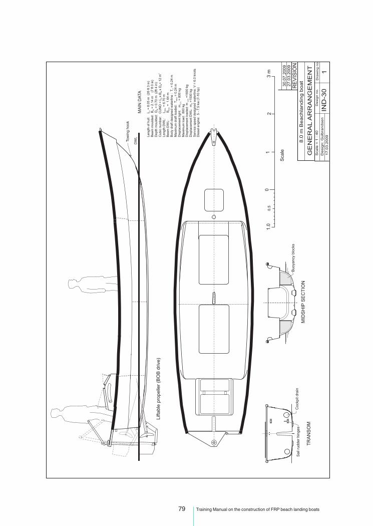
79 Training Manual on the construction of FRP beach landing boats

80 Training Manual on the construction of FRP beach landing boats

81 Training Manual on the construction of FRP beach landing boats

82 Training Manual on the construction of FRP beach landing boats

83 Training Manual on the construction of FRP beach landing boats

84 Training Manual on the construction of FRP beach landing boats

85 Training Manual on the construction of FRP beach landing boats

86 Training Manual on the construction of FRP beach landing boats

87 Training Manual on the construction of FRP beach landing boats

88 Training Manual on the construction of FRP beach landing boats

89 Training Manual on the construction of FRP beach landing boats

90 Training Manual on the construction of FRP beach landing boats

91 Training Manual on the construction of FRP beach landing boats

92 Training Manual on the construction of FRP beach landing boats

93 Training Manual on the construction of FRP beach landing boats
IND - 30A8 m BEACH-LANDING BOAT
1. General arrangement2. Sail rig - Tamil Nadu3. Midship section4. FRP layup5. Bottom stiffening6. Propeller shaft tunnel7. Centreboard case8. Frame 19. Frame 2
10. Frame 311. Frame 412. Frame 513. Lower deck14. Coaming details15. Upper deck16. Non-skid and details17. Rail
18. Hatch lock 119. Hatch lock 220. Sailing rudder21. Rudder hinge22. Transom assembly23. Centreboard24. Towing hook25. Mooring bitt26. Buoyancy blocks27. Right after capsize28. Engine installation A29. Engine installation A30. Side view31. Engine installation B32. Engine bed33. Engine hatch cover
93 Training Manual on the construction of FRP beach landing boats

94 Training Manual on the construction of FRP beach landing boats
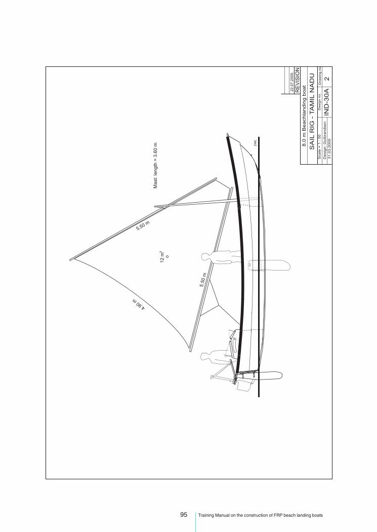
95 Training Manual on the construction of FRP beach landing boats

96 Training Manual on the construction of FRP beach landing boats

97 Training Manual on the construction of FRP beach landing boats

98 Training Manual on the construction of FRP beach landing boats

99 Training Manual on the construction of FRP beach landing boats

100 Training Manual on the construction of FRP beach landing boats
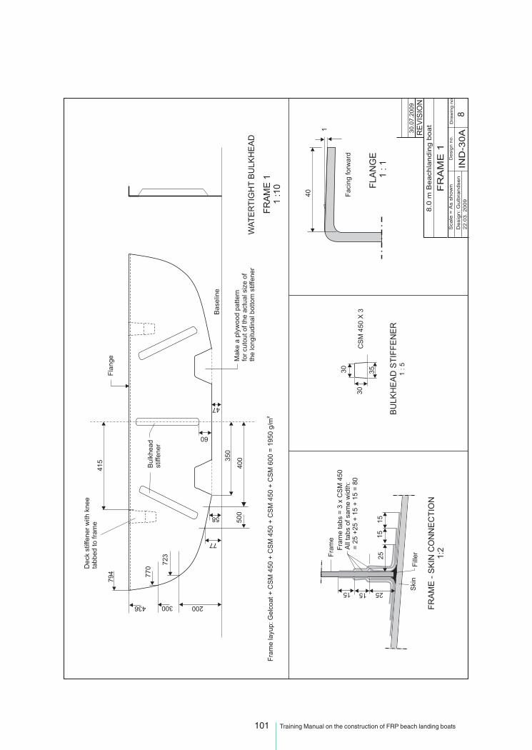
101 Training Manual on the construction of FRP beach landing boats

102 Training Manual on the construction of FRP beach landing boats

103 Training Manual on the construction of FRP beach landing boats

104 Training Manual on the construction of FRP beach landing boats
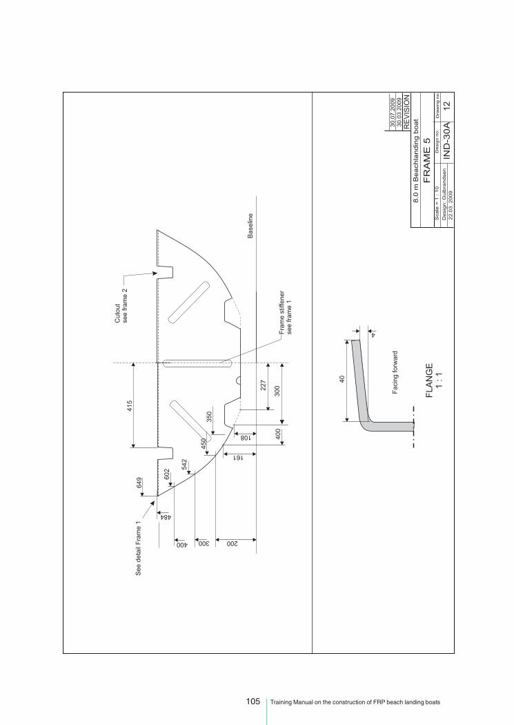
105 Training Manual on the construction of FRP beach landing boats

106 Training Manual on the construction of FRP beach landing boats

107 Training Manual on the construction of FRP beach landing boats

108 Training Manual on the construction of FRP beach landing boats

109 Training Manual on the construction of FRP beach landing boats

110 Training Manual on the construction of FRP beach landing boats

111 Training Manual on the construction of FRP beach landing boats

112 Training Manual on the construction of FRP beach landing boats
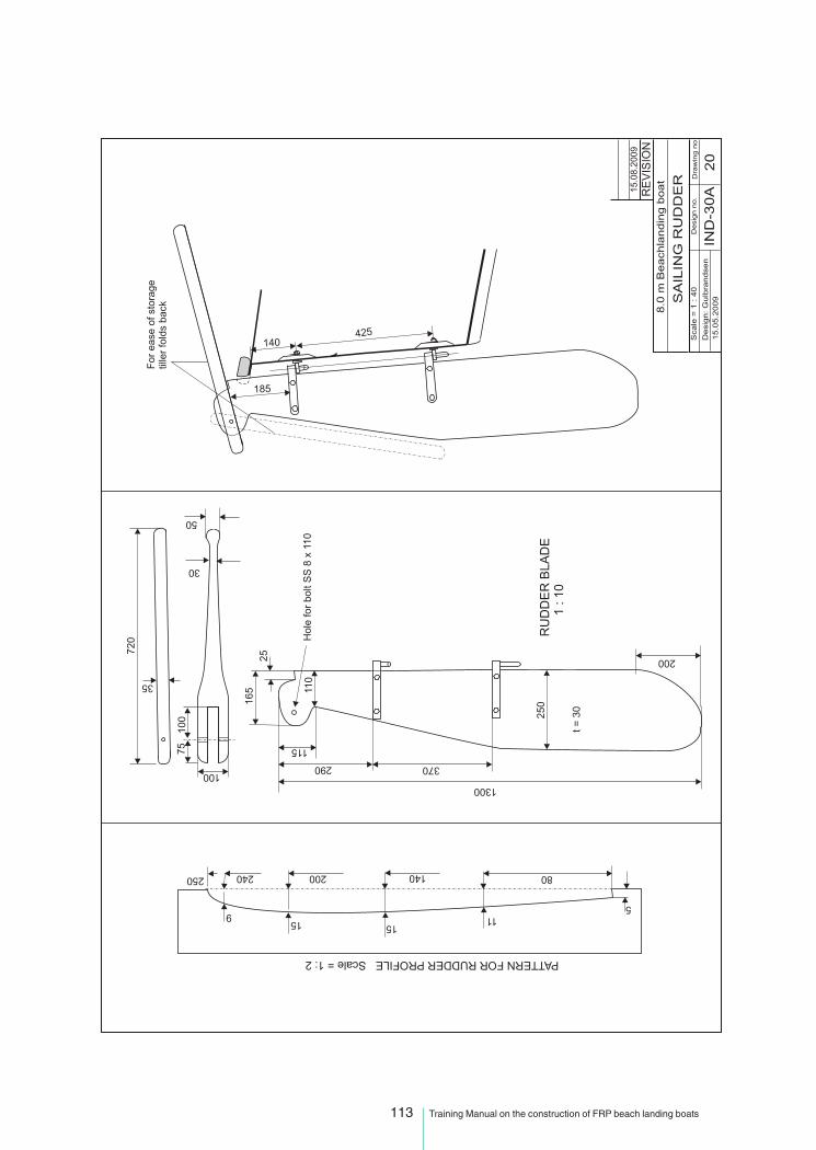
113 Training Manual on the construction of FRP beach landing boats

114 Training Manual on the construction of FRP beach landing boats
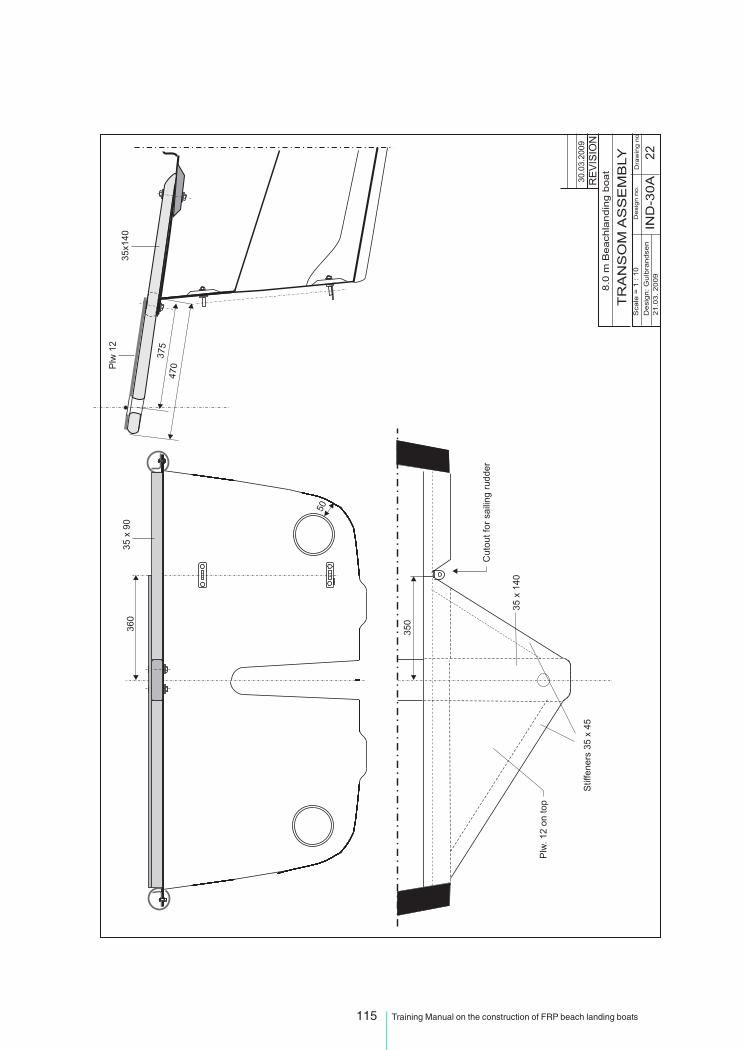
115 Training Manual on the construction of FRP beach landing boats

116 Training Manual on the construction of FRP beach landing boats

117 Training Manual on the construction of FRP beach landing boats

118 Training Manual on the construction of FRP beach landing boats

119 Training Manual on the construction of FRP beach landing boats

120 Training Manual on the construction of FRP beach landing boats
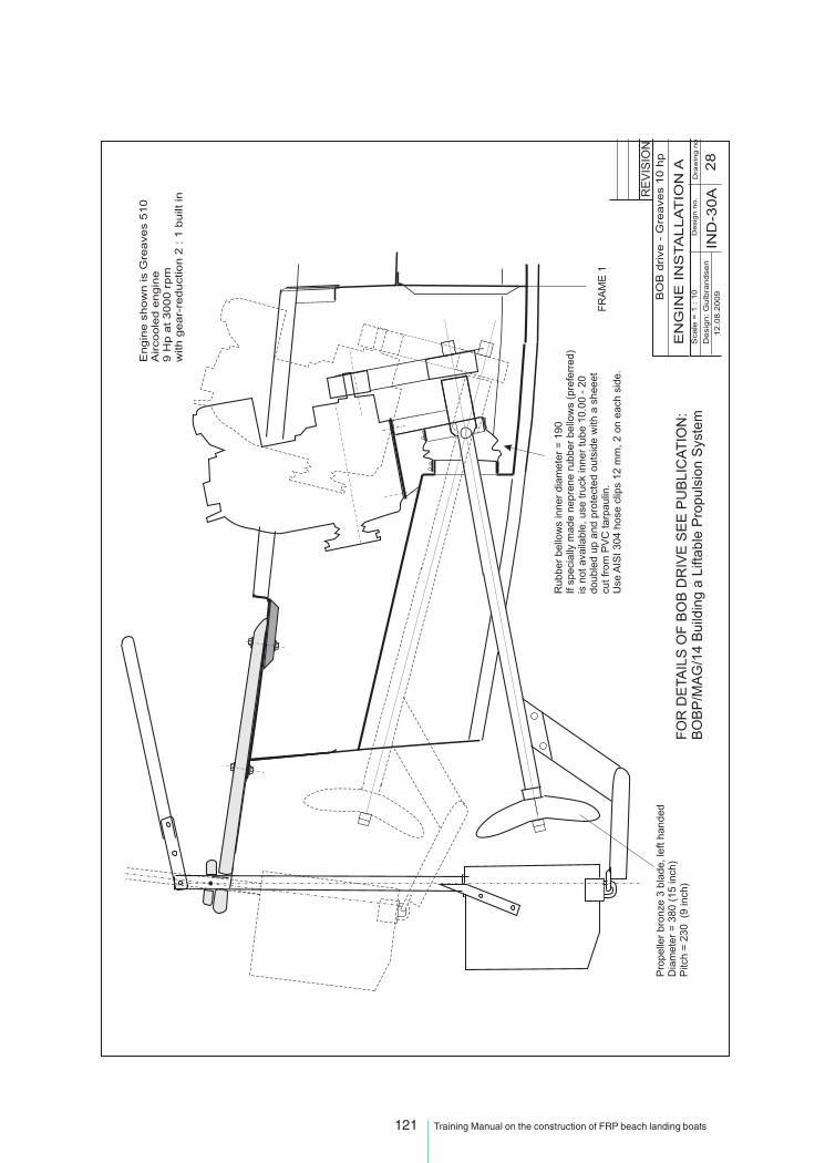
121 Training Manual on the construction of FRP beach landing boats

122 Training Manual on the construction of FRP beach landing boats

123 Training Manual on the construction of FRP beach landing boats

124 Training Manual on the construction of FRP beach landing boats

125 Training Manual on the construction of FRP beach landing boats

126 Training Manual on the construction of FRP beach landing boats

127 Training Manual on the construction of FRP beach landing boats
Annex 4: FRP CONSTRUCTION STANDARDS*
1.1 Definitions
For the purpose of these recommendations, unless expressly provided otherwise, the following definitionsapply:
1.1.1 Breadth (B)** is the maximum breadth of the vessel, measured at maximum beam to the mouldedline of the frame in a vessel with a metal shell and to the outer surface of the hull in a vessel with a shellof any other material.
1.1.2 Competent authority is the Government of the State whose flag the vessel is entitled to fly. Thecompetent authority may delegate certain of its duties to entities authorized by it and that it deems suitablyqualified to undertake those duties.
1.1.3 Cubic Numeral (CuNo)** is the result of multiplying LOA x B x D.
1.1.4 Decked vessel is a vessel having a fixed watertight deck covering the entire hull above thedeepest operating waterline. Where open wells or cockpits are fitted in this deck the vessel is considereda decked vessel if flooding of the well or cockpit will not endanger the vessel.
1.1.5 The depth (D)** is the moulded depth amidships.
1.1.6 Design categories
The categories here indicate sea and wind conditions for which a vessel is assessed by this standard tobe suitable, provided the vessel is correctly operated and at a speed appropriate to the prevailing seastate.
1 Design category ACategory of vessels considered suitable to operate in seas with significant wave heightsabove 4 m and wind speeds in excess of Beaufort Force 8 (19 m/s), but excluding abnormalconditions, e.g. hurricanes.
2 Design category BCategory of vessels considered suitable to operate in seas with significant wave heights upto 4 m and winds of Beaufort Force 8 (19 m/s), or less.
3 Design category CCategory of vessels considered suitable to operate in seas with significant wave heights upto 2 m and a typical steady wind force of Beaufort Force 6 (12 m/s), or less.
4 Design category DCategory of vessels considered suitable to operate in waters with significant wave heightsup to and including 0.30 m with occasional waves of 0.5 m height, for example from passingvessels, and a typical steady wind force of Beaufort 4 (7 m/s), or less.
1.1.7 Length overall (LOA)** should be taken as the distance in a straight line parallel to the designwaterline, between the foremost point of the bow to the aftermost point of the stern.
1.1.8 Undecked vessel is a vessel which is not a decked vessel.
* Drawn from the draft FAO/ILO/IMO Safety recommendations for decked fishing vessels of less than 12 metres in length andundecked fishing vessels.
** The dimensions are illustrated in Appendix 1.

128 Training Manual on the construction of FRP beach landing boats
DECKED BOATS - MEASUREMENTS
Appendix 1: ILLUSTRATION OF TERMS USED IN THE DEFINITIONS
LENGTH OVER ALL (LOA)BREADTH (B)DEPTH (D)
LOA
1/2 LOA
AMIDSHIPS
D
B Measured at maximum beam
B
Deck
Removable fender
D
D

129 Training Manual on the construction of FRP beach landing boats
OPEN BOATS - MEASUREMENTS
LENGTH OVER ALL (LOA)BREADTH (B)DEPTH (D)
LOA
Measured at
widest beam
D
B
Measured at 1/2 LOA
LOA
1/2 LOA
D
AMIDSHIPS
LOA
B
Removable fender
D
D
B

130 Training Manual on the construction of FRP beach landing boats
LOA x B x D = Cubic numeral (CuNo)
Loa
D
B
DD
Flush and well deckedvessels
Open vessels

131 Training Manual on the construction of FRP beach landing boats
Appendix 2: RECOMMENDED CONSTRUCTION STANDARDS FOR GRP FISHING VESSELS
PART I - GENERAL
1. Scope
1.1 These construction standards apply to decked vessels of less than 12 m in length and undeckedvessels of any size.
1.2 In general the standards apply to vessels of conventional form and of glass reinforced plasticconstruction (GRP), i.e. single hull vessels of glass rovings and mat and polyester resin construction thatin general should consist of:
• moulded hull of single-skin construction;
• deck of GRP sheathed plywood, GRP or traditional timber construction;
• transverse framing;
• longitudinal structure including gunwale, stringers and engine beds;
• in small vessels internal furniture and hull form may provide adequate stiffening.
7
12
34
56
Key1 transom2 gunwale stringer3 bulkhead4 side longitudinal stiffener (stringer)5 web frame6 deep floor7 bottom longitudinal stiffener (girder or stringer).
Typical longitudinal framing in a GRP vessel
Key1 transom2 bulkhead3 frame4 bulkhead5 bottom girder6 deep floor7 deep floor
Typical transverse framing in a GRP vessel
1
23
4
56
7
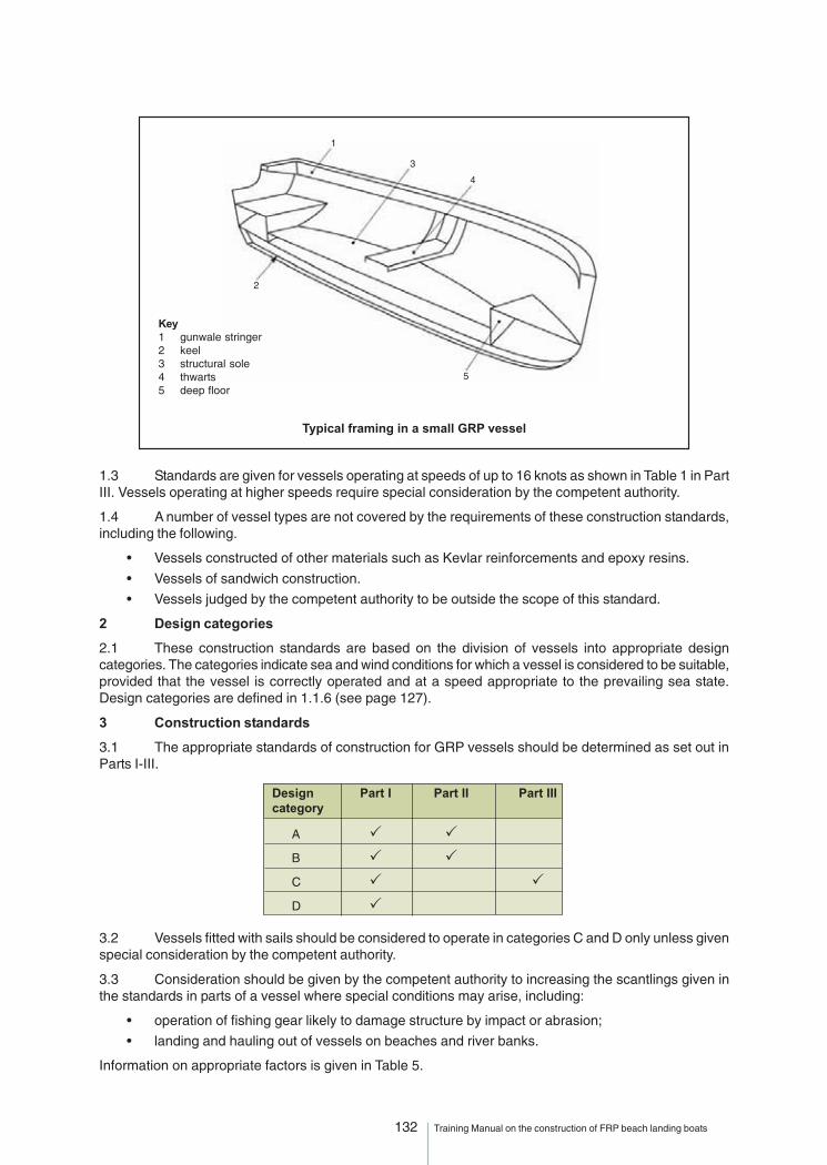
132 Training Manual on the construction of FRP beach landing boats
1.3 Standards are given for vessels operating at speeds of up to 16 knots as shown in Table 1 in PartIII. Vessels operating at higher speeds require special consideration by the competent authority.
1.4 A number of vessel types are not covered by the requirements of these construction standards,including the following.
• Vessels constructed of other materials such as Kevlar reinforcements and epoxy resins.
• Vessels of sandwich construction.
• Vessels judged by the competent authority to be outside the scope of this standard.
2 Design categories
2.1 These construction standards are based on the division of vessels into appropriate designcategories. The categories indicate sea and wind conditions for which a vessel is considered to be suitable,provided that the vessel is correctly operated and at a speed appropriate to the prevailing sea state.Design categories are defined in 1.1.6 (see page 127).
3 Construction standards
3.1 The appropriate standards of construction for GRP vessels should be determined as set out inParts I-III.
3.2 Vessels fitted with sails should be considered to operate in categories C and D only unless givenspecial consideration by the competent authority.
3.3 Consideration should be given by the competent authority to increasing the scantlings given inthe standards in parts of a vessel where special conditions may arise, including:
• operation of fishing gear likely to damage structure by impact or abrasion;
• landing and hauling out of vessels on beaches and river banks.
Information on appropriate factors is given in Table 5.
Design Part I Part II Part IIIcategory
A � �
B � �
C � �
D �
Key1 gunwale stringer2 keel3 structural sole4 thwarts5 deep floor
Typical framing in a small GRP vessel
1
3
4
2
5

133 Training Manual on the construction of FRP beach landing boats
4 Construction standards for GRP vessels of all design categories
4.1 Materials
4.1.1 Resins should be approved for marine use and be mixed and used in accordance with themanufacturers’ recommendations.
4.1.2 Glass reinforcements should be approved for marine use and may be in the form of choppedstrand mat, woven rovings, fabric, powder bound mat or other approved materials.
4.1.3 Colour pigment may be used in the gelcoat sufficient to give a satisfactory colour; the amountused should be in accordance with the manufacturers’ recommendations. No pigment should be used inthe lay-up resin of the hull laminates.
4.1.4 Formers for stiffeners should be of rigid foam, timber, metal or other approved materials. Wheretimber is used it should have a moisture content of not more than 15 percent. A common type of former fortop-hat stiffeners is made of one layer of mat in a mould of the required stiffener dimensions.
4.1.5 Careful attention should be paid to the manufacturers’ recommendations concerning the storageand use dates of the materials to be used.
4.2 Workshop practice
4.2.1 All building activities should be carried out under a fixed roof and preferably in an enclosedworkshop.
4.2.2 The cleanliness of the workshop is important for the health of workers and to prevent contaminationof the resin and reinforcements.
4.2.3 Waste material, dust, sand and other contaminants should be removed immediately from theworkshop.
4.2.4 The moulding area should be kept clear of dust and accumulation of waste material that couldcontaminate the mould surfaces.
4.2.5 The recommended humidity and temperature ranges under which laminating may take placeare: temperature 15 to 25 degrees C, humidity 70 percent. The moulding process should cease if thefollowing limits are reached: temperature <13 or >32 degrees C, humidity >80 percent.
4.2.6 The workshop should be as free as practical from dust and fumes to allow comfortable and safeworking conditions. Styrene fumes are heavier than air and should be removed from moulds by the use ofmechanical ventilation systems.
4.2.7 Completed mouldings should not be taken outside the workshop environment within seven daysof the start of the moulding process. Where mouldings are moved outside after this period they should beprotected from rain.
4.2.8 The addition of catalyst to polyester products should be strictly controlled within the limits set bythe manufacturers. Tables giving amounts of catalyst/resin should be available in the workshop.
4.2.9 The catalyst must be properly dispersed through the resin by very thorough mixing.
4.2.10 Where a primary bond is to be achieved, little preparation of the surface is required prior tofurther laminating or bonding. A primary bond is generally achieved if the surface has cured for about24 to 48 hours and is still chemically active, allowing a chemical bond.
4.2.11 Where a secondary bond is to be achieved, additional surface preparation is required in the formof abrasion and cleaning. A secondary bond is achieved when the surface has cured for over 48 hoursand is no longer chemically active; in this case, the bond relies on the adhesive properties of the resin.
4.3 Laminate lay-up
4.3.1 The outside surface of all laminates should have a layer of gelcoat or be treated with equivalentsurface protection after completion of moulding. This layer should be 0.4 to 0.6 mm thick.
4.3.2 The gelcoat should only be left exposed in accordance with the manufacturers’ recommendations;generally a maximum of 24 hours.
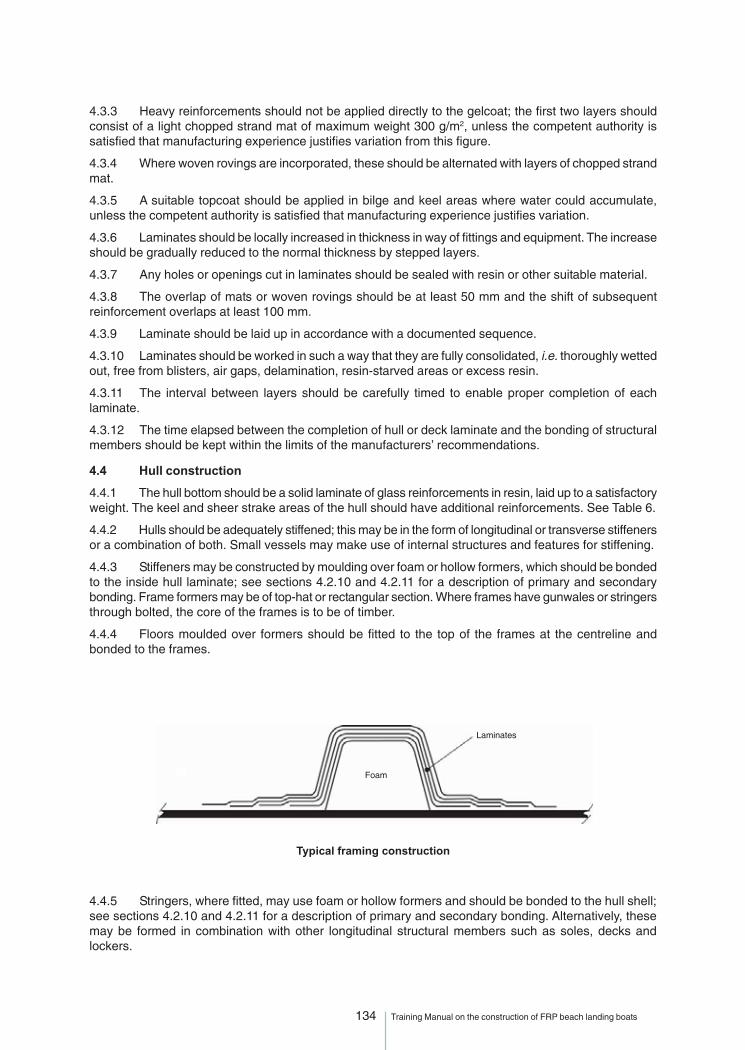
134 Training Manual on the construction of FRP beach landing boats
4.3.3 Heavy reinforcements should not be applied directly to the gelcoat; the first two layers shouldconsist of a light chopped strand mat of maximum weight 300 g/m2, unless the competent authority issatisfied that manufacturing experience justifies variation from this figure.
4.3.4 Where woven rovings are incorporated, these should be alternated with layers of chopped strandmat.
4.3.5 A suitable topcoat should be applied in bilge and keel areas where water could accumulate,unless the competent authority is satisfied that manufacturing experience justifies variation.
4.3.6 Laminates should be locally increased in thickness in way of fittings and equipment. The increaseshould be gradually reduced to the normal thickness by stepped layers.
4.3.7 Any holes or openings cut in laminates should be sealed with resin or other suitable material.
4.3.8 The overlap of mats or woven rovings should be at least 50 mm and the shift of subsequentreinforcement overlaps at least 100 mm.
4.3.9 Laminate should be laid up in accordance with a documented sequence.
4.3.10 Laminates should be worked in such a way that they are fully consolidated, i.e. thoroughly wettedout, free from blisters, air gaps, delamination, resin-starved areas or excess resin.
4.3.11 The interval between layers should be carefully timed to enable proper completion of eachlaminate.
4.3.12 The time elapsed between the completion of hull or deck laminate and the bonding of structuralmembers should be kept within the limits of the manufacturers’ recommendations.
4.4 Hull construction
4.4.1 The hull bottom should be a solid laminate of glass reinforcements in resin, laid up to a satisfactoryweight. The keel and sheer strake areas of the hull should have additional reinforcements. See Table 6.
4.4.2 Hulls should be adequately stiffened; this may be in the form of longitudinal or transverse stiffenersor a combination of both. Small vessels may make use of internal structures and features for stiffening.
4.4.3 Stiffeners may be constructed by moulding over foam or hollow formers, which should be bondedto the inside hull laminate; see sections 4.2.10 and 4.2.11 for a description of primary and secondarybonding. Frame formers may be of top-hat or rectangular section. Where frames have gunwales or stringersthrough bolted, the core of the frames is to be of timber.
4.4.4 Floors moulded over formers should be fitted to the top of the frames at the centreline andbonded to the frames.
4.4.5 Stringers, where fitted, may use foam or hollow formers and should be bonded to the hull shell;see sections 4.2.10 and 4.2.11 for a description of primary and secondary bonding. Alternatively, thesemay be formed in combination with other longitudinal structural members such as soles, decks andlockers.
Foam
Laminates
Typical framing construction
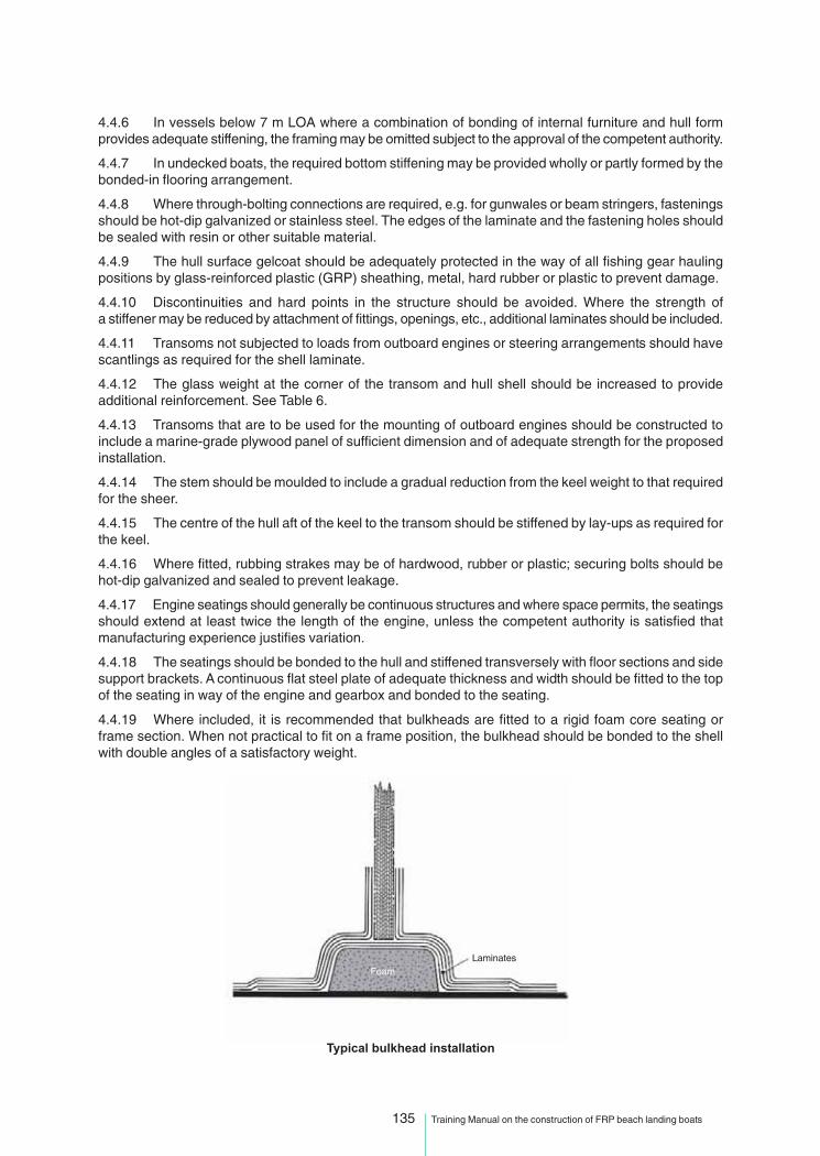
135 Training Manual on the construction of FRP beach landing boats
4.4.6 In vessels below 7 m LOA where a combination of bonding of internal furniture and hull formprovides adequate stiffening, the framing may be omitted subject to the approval of the competent authority.
4.4.7 In undecked boats, the required bottom stiffening may be provided wholly or partly formed by thebonded-in flooring arrangement.
4.4.8 Where through-bolting connections are required, e.g. for gunwales or beam stringers, fasteningsshould be hot-dip galvanized or stainless steel. The edges of the laminate and the fastening holes shouldbe sealed with resin or other suitable material.
4.4.9 The hull surface gelcoat should be adequately protected in the way of all fishing gear haulingpositions by glass-reinforced plastic (GRP) sheathing, metal, hard rubber or plastic to prevent damage.
4.4.10 Discontinuities and hard points in the structure should be avoided. Where the strength ofa stiffener may be reduced by attachment of fittings, openings, etc., additional laminates should be included.
4.4.11 Transoms not subjected to loads from outboard engines or steering arrangements should havescantlings as required for the shell laminate.
4.4.12 The glass weight at the corner of the transom and hull shell should be increased to provideadditional reinforcement. See Table 6.
4.4.13 Transoms that are to be used for the mounting of outboard engines should be constructed toinclude a marine-grade plywood panel of sufficient dimension and of adequate strength for the proposedinstallation.
4.4.14 The stem should be moulded to include a gradual reduction from the keel weight to that requiredfor the sheer.
4.4.15 The centre of the hull aft of the keel to the transom should be stiffened by lay-ups as required forthe keel.
4.4.16 Where fitted, rubbing strakes may be of hardwood, rubber or plastic; securing bolts should behot-dip galvanized and sealed to prevent leakage.
4.4.17 Engine seatings should generally be continuous structures and where space permits, the seatingsshould extend at least twice the length of the engine, unless the competent authority is satisfied thatmanufacturing experience justifies variation.
4.4.18 The seatings should be bonded to the hull and stiffened transversely with floor sections and sidesupport brackets. A continuous flat steel plate of adequate thickness and width should be fitted to the topof the seating in way of the engine and gearbox and bonded to the seating.
4.4.19 Where included, it is recommended that bulkheads are fitted to a rigid foam core seating orframe section. When not practical to fit on a frame position, the bulkhead should be bonded to the shellwith double angles of a satisfactory weight.
Laminates
Typical bulkhead installation
Foam

136 Training Manual on the construction of FRP beach landing boats
4.4.20 Bolt connections should be well sealed and glassed over to prevent leakage.
4.4.21 Consideration should be given to including easily replaceable sacrificial structures in locationswhere impact or abrasion may occur. These include areas subject to wear such as gunwales and keelsand areas subject to impact or abrasion by fishing gear.
4.5 Deck construction
4.5.1 Decks may be of GRP sheathed plywood, GRP or traditional timber construction.
4.5.2 A beam shelf or stringer should be bonded to the hull shell to support the deck beams. A systemcombining through bolting and bonding is recommended.
4.5.3 Deck beams should be fitted at each frame position; with longitudinal stiffening provided byhatches and carlings as required.
4.5.4 Decks in way of gallows, warp leads, deck machinery and heavy work positions should haveadditional stiffening and pillars to the approval of the competent authority.
4.5.5 Main beams should be fitted in way of all deck openings, machinery and deckhouse casings andin way of masts and heavy deck machinery.
4.5.6 Where deck beams of timber are fitted, reference should be made to appropriate constructionstandards for wooden vessels.
4.5.7 Where decks and deck beams are of GRP construction, openings in the deck may be stiffenedby forming continuously moulded flanges, the weight of which should be 25 percent greater than thelaid-up deck laminate weight. Deck openings over 500 mm in length should be fitted with longitudinalstiffening.
4.5.8 Plywood decks should be bolted and bonded to the beam shelf and bonded to the hull. Thecomplete deck area should be sheathed with a GRP laminate. Special attention should be paid to thesheathing in way of working areas that may require extra protection.
4.5.9 Where laid timber planked decking is used for decks, reference should be made to appropriateconstruction standards for wooden vessels.
PART II – RECOMMENDED CONSTRUCTION STANDARDS FOR GRP VESSELS OF DESIGNCATEGORIES A AND B
1 Introduction
1.1 The construction standards described here should be applied to all decked vessels in designcategories A and B.
2 Construction
2.1 In general, the requirements of Part I should be complied with in addition to the requirementsbelow.
2.2 The strength and construction of the hull, deck and other structures should be built to withstandall foreseeable conditions of the intended service.
2.3 All vessels should meet requirements that are compatible with a recognized GRP vesselconstruction standard* or an equivalent standard and be built to the satisfaction of the competent authority.
* The standards include:
1. the Nordic Boat Standard;
2. the construction rules of the United Kingdom Sea Fish Industry Authority (Seafish); and
3. the construction rules of recognized organizations.
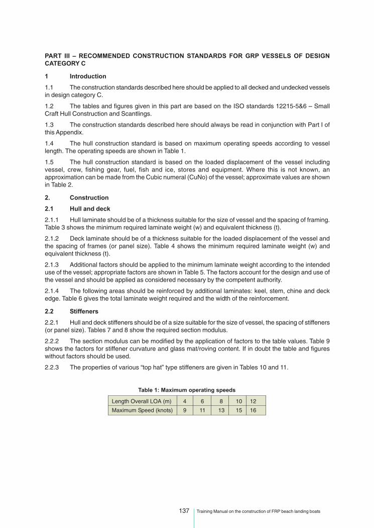
137 Training Manual on the construction of FRP beach landing boats
PART III – RECOMMENDED CONSTRUCTION STANDARDS FOR GRP VESSELS OF DESIGNCATEGORY C
1 Introduction
1.1 The construction standards described here should be applied to all decked and undecked vesselsin design category C.
1.2 The tables and figures given in this part are based on the ISO standards 12215-5&6 – SmallCraft Hull Construction and Scantlings.
1.3 The construction standards described here should always be read in conjunction with Part I ofthis Appendix.
1.4 The hull construction standard is based on maximum operating speeds according to vessellength. The operating speeds are shown in Table 1.
1.5 The hull construction standard is based on the loaded displacement of the vessel includingvessel, crew, fishing gear, fuel, fish and ice, stores and equipment. Where this is not known, anapproximation can be made from the Cubic numeral (CuNo) of the vessel; approximate values are shownin Table 2.
2. Construction
2.1 Hull and deck
2.1.1 Hull laminate should be of a thickness suitable for the size of vessel and the spacing of framing.Table 3 shows the minimum required laminate weight (w) and equivalent thickness (t).
2.1.2 Deck laminate should be of a thickness suitable for the loaded displacement of the vessel andthe spacing of frames (or panel size). Table 4 shows the minimum required laminate weight (w) andequivalent thickness (t).
2.1.3 Additional factors should be applied to the minimum laminate weight according to the intendeduse of the vessel; appropriate factors are shown in Table 5. The factors account for the design and use ofthe vessel and should be applied as considered necessary by the competent authority.
2.1.4 The following areas should be reinforced by additional laminates: keel, stem, chine and deckedge. Table 6 gives the total laminate weight required and the width of the reinforcement.
2.2 Stiffeners
2.2.1 Hull and deck stiffeners should be of a size suitable for the size of vessel, the spacing of stiffeners(or panel size). Tables 7 and 8 show the required section modulus.
2.2.2 The section modulus can be modified by the application of factors to the table values. Table 9shows the factors for stiffener curvature and glass mat/roving content. If in doubt the table and figureswithout factors should be used.
2.2.3 The properties of various “top hat” type stiffeners are given in Tables 10 and 11.
Table 1: Maximum operating speeds
Length Overall LOA (m) 4 6 8 10 12
Maximum Speed (knots) 9 11 13 15 16

138 Training Manual on the construction of FRP beach landing boats
Table 2: Cubic numeral and loaded displacement
Cubic numeral Undecked Vessel Decked Vessel(CuNo) Approximate Loaded Approximate Loaded
Displacement Displacement
m3 kg kg4 600 -
6 900 -
8 1200 -
10 1500 -
12 1800 -
14 2100 -
16 2400 -
18 2700 -
20 3000 4800
25 3750 6000
30 4500 7200
35 - 8400
40 - 9600
45 - 10800
50 - 12000
60 - 14400
70 - 16800
80 - 19200
90 - 21600
100 - 24000
Note: The figures given are approximate and where possible it is better to obtainaccurate displacement figures from calculations and measurements.
Table 3: Table of minimum hull laminate weight
Panel 500 500 600 600 800 800 1000 1000 1200 1200 1400 1400Width(mm)
Loaded t w (min) t w t w t w t w t wDispl (kg) mm g/m2 mm g/m2 mm g/m2 mm g/m2 mm g/m2 mm g/m2
250 3.9 1670 4.4 1880 5.2 2250 6.6 2810 7.9 3370 9.2 3930
500 4.3 1860 4.9 2090 5.8 2490 6.9 2960 8.3 3550 9.7 4140
1000 4.8 2070 5.4 2330 6.5 2780 7.7 3280 9.2 3930 10.7 4580
2000 5.4 2330 6.1 2620 7.3 3130 8.6 3690 10.3 4400 12.0 5140
4000 6.2 2640 6.9 2960 8.3 3540 9.8 4180 11.5 4930 13.4 5760
6000 6.6 2840 7.5 3190 8.9 3820 10.5 4500 12.3 5280 14.4 6160
8000 7.0 3000 7.9 3370 9.4 4030 11.1 4750 12.9 5530 15.1 6450
10000 7.3 3130 8.2 3520 9.8 4200 11.6 4960 13.4 5740 15.6 6700
12000 7.6 3240 8.5 3650 10.2 4360 12.0 5140 13.8 5920 16.1 6900
15000 7.9 3390 8.9 3810 10.6 4550 12.5 5370 14.3 6140 16.7 7160
18000 8.2 3510 9.2 3950 11.0 4720 13.0 5570 14.8 6330 17.2 7380
20000 8.4 3590 9.4 4030 11.3 4820 13.3 5680 15.1 6470 17.5 7510
22000 8.5 3660 9.6 4110 11.5 4910 13.5 5790 15.4 6590 17.8 7630
25000 8.8 3750 9.8 4220 11.8 5040 13.9 5950 15.8 6770 18.2 7790
Note: The figures listed for a 500mm panel width are the minimum figures to be used and weights below this should not be used after theapplication of factors.

139 Training Manual on the construction of FRP beach landing boats
Table 4: Table of minimum deck laminate weight
Panel 500 500 600 600 700 700Width (mm)
Length t w t w t wOverall (m) mm g/m2 mm g/m2 mm g/m2
4 3.3 1420 3.8 1650 4.5 1920
5 3.5 1510 3.8 1650 4.5 1920
6 3.8 1650 3.8 1650 4.5 1920
7 4.0 1700 4.0 1700 4.5 1920
8 4.2 1790 4.2 1790 4.5 1920
9 4.4 1880 4.4 1880 4.5 1920
10 4.6 1970 4.6 1970 4.6 1970
11 4.8 2060 4.8 2060 4.8 2060
12 5.0 2150 5.0 2150 5.0 2150
13 5.2 2240 5.2 2240 5.2 2240
14 5.5 2340 5.5 2340 5.5 2340
15 5.7 2430 5.7 2430 5.7 2430
Notes: 1. The figures given show w, the minimum required weight in g/m2 of dry laminate to be used inconstruction.2. The table shows weights of laminates where chopped strand mat is 90 to 100% of the total glassweight. Correction for other combinations of mat and roving are accounted for in Table 5.3. The figures listed for a 500mm panel width are the minimum figures to be used and weights belowthis should not be used after the application of factors.
Table 5: Table of factors applied to minimum laminate
Panel Curvature Factor, Fcc/b 0.03 and 0.06 0.09 0.12 0.15 0.18 and
below above
Fc 1 0.9 0.8 0.7 0.6 0.5
Glass Mat/Roving Factor, Fw
R 0.3 0.4 0.5 0.6 0.7 0.8 0.9 - 1.0
Glassfibre content 0.41 0.39 0.37 0.35 0.33 0.32 0.30
Mat/Roving Factor Fw 0.89 0.91 0.93 0.95 0.97 0.98 1.0
Where R =
Weight of Chopped Strand Mat (CSM) in g/m2
Total weight of Glassfibre in g/m2
Usage Factor Type Conditions Factor
Fv Vessel landing River landing Calm water 1.00
Harbour landing Impact on quays, walls etc 1.05
Beach landing Small surf 1.10
Beach landing Large surf 1.20
Fg Fishing gear Light fishing gear (nets & lines) Damage unlikely 1.00
Heavy fishing gear (trawl) Impact structure 1.10
Usage Factor = Fv x Fg
Notes: 1. The minimum required weight in g/m2 of dry laminate should be multiplied by the relevant factors from thetables above. Thus the required weight of dry laminate = minimum weight x Fc x Fw x Fv x Fg.2. The total factor applied (Fc x Fw x Fv x Fg) need not be greater than 1.2.
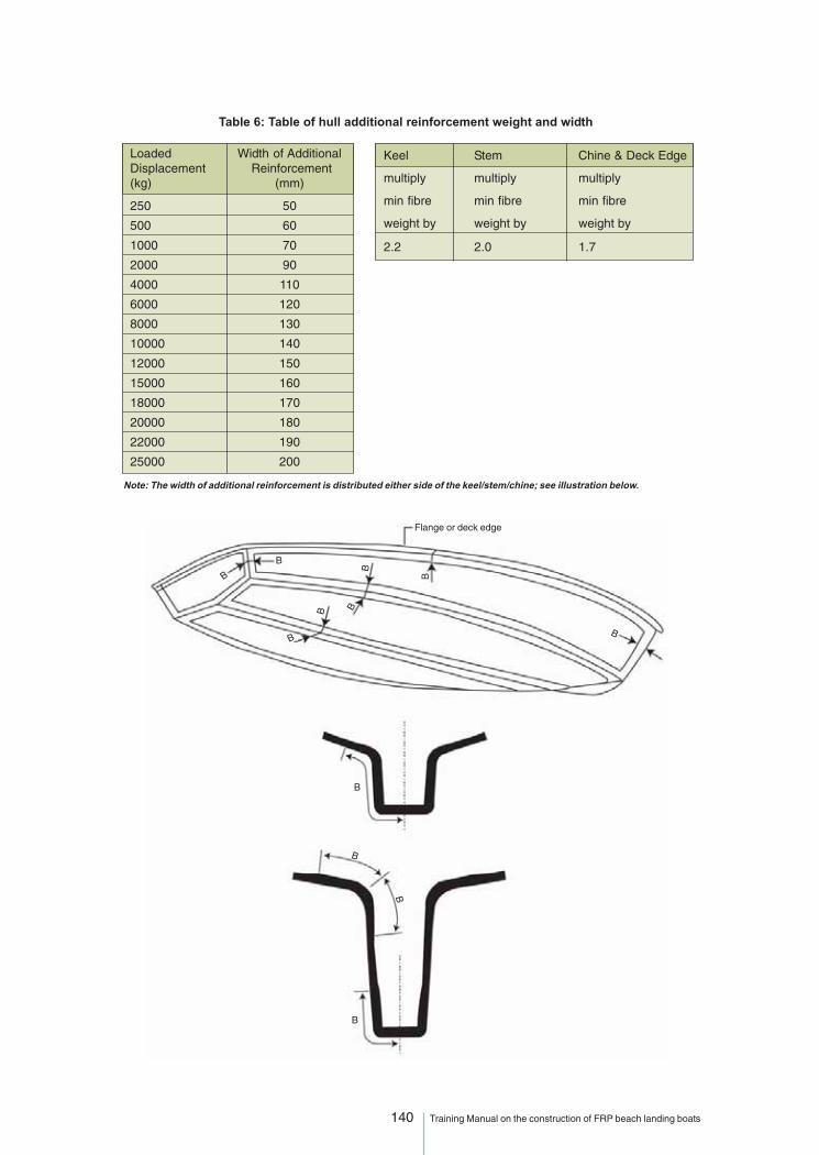
140 Training Manual on the construction of FRP beach landing boats
Table 6: Table of hull additional reinforcement weight and width
Loaded Width of AdditionalDisplacement Reinforcement(kg) (mm)
250 50
500 60
1000 70
2000 90
4000 110
6000 120
8000 130
10000 140
12000 150
15000 160
18000 170
20000 180
22000 190
25000 200
Keel Stem Chine & Deck Edge
multiply multiply multiply
min fibre min fibre min fibre
weight by weight by weight by
2.2 2.0 1.7
Note: The width of additional reinforcement is distributed either side of the keel/stem/chine; see illustration below.
B
B
B
B B
B
B
B
B
Flange or deck edge
B
B
B

141 Training Manual on the construction of FRP beach landing boats
Table 7: Hull stiffeners section modulus – SM cm3
Loaded Stiffener spacing s = 500 mmdisplacement Stiffener span l (mm)mLDC(kg) 500 750 1000 1250 1500 1750 2000
500 2.5 4.6 7.1 11 16 22 28
1000 3.1 5.9 9.0 13 19 26 34
5000 5.4 10 16 21 30 41 54
10000 7.0 13 20 28 38 52 68
15000 8.2 15 24 33 44 60 78
20000 9.2 17 27 36 48 65 86
25000 10 19 29 40 52 70 92
Loaded Stiffener spacing s = 600 mmdisplacement Stiffener span l (mm)mLDC(kg) 500 750 1000 1250 1500 1750 2000
500 2.8 5.3 8.5 13 19 26 34
1000 3.5 6.6 10 16 23 32 41
5000 6.1 12 18 25 37 50 65
10000 8.0 15 23 32 46 63 82
15000 9.3 18 27 37 53 71 93
20000 10 20 30 41 58 79 103
25000 11 22 33 45 62 85 110
Loaded Stiffener spacing s = 700 mmdisplacement Stiffener span l (mm)mLDC(kg) 500 750 1000 1250 1500 1750 2000
500 3.1 5.9 10 16 22 31 40
1000 3.9 7.3 12 19 27 37 48
5000 6.8 13 21 32 46 63 82
10000 9.0 17 26 37 54 73 95
15000 10 20 30 43 61 83 109
20000 12 22 34 47 67 92 120
25000 13 24 37 50 72 99 129
Loaded Stiffener spacing s = 800 mmdisplacement Stiffener span l (mm)mLDC(kg) 500 750 1000 1250 1500 1750 2000
500 3.4 6.4 11 18 26 35 46
1000 4.3 8.0 14 22 31 42 55
5000 7.5 14 22 34 49 66 87
10000 9.7 18 28 43 61 83 109
15000 11 21 33 49 70 95 124
20000 13 24 37 53 77 105 137
25000 14 26 40 58 83 112 147

142 Training Manual on the construction of FRP beach landing boats
Table 8: Deck stiffeners section modulus – SM cm3
Stiffener spacing s = 600 mm
Stiffener span l (mm)
1000 1500 2000 2500 3000 3500 4000
9 19 34 53 77 104 136
Stiffener spacing s = 700 mm
Stiffener span l (mm)
1000 1500 2000 2500 3000 3500 4000
9.8 20 36 56 81 110 143
Table 9: Stiffener - curvature factor fcs
c 0.03 and 0.06 0.09 0.12 0.15 0.18 andl below above
fcs 1.0 0.90 0.80 0.70 0.60 0.50
Stiffener mat - roving factor fws
R 0.3 0.4 0.5 0.6 0.7 0.8 0.9 – 1.0
Glass fibre content 0.32 0.31 0.30 0.28 0.27 0.26 0.25
fws 0.72 0.75 0.78 0.87 0.91 0.96 1.00
Stiffener spacing s = 500 mm
Stiffener span l (mm)
1000 1500 2000 2500 3000 3500 4000
7.0 16 28 44 64 87 113

143 Training Manual on the construction of FRP beach landing boats
Table 10: Top hat stiffeners
Low top hat stiffener
Glass content: g = 0.30(Chopped strand mat CSM)
Square top hat stiffener
Dimensions of Plating Stiffener Sectionformer thickness glass weight modulush bb bc t w SMMINmm mm mm mm g/m2 cm3
25 25 20 5 600 1.510 600 2.215 600 4.6
40 40 35 5 600 3.610 600 4.415 600 6.3
50 50 45 5 900 8.210 900 9.515 900 12
60 60 50 2 1200 1510 1200 1715 1200 19
75 75 65 5 1200 2310 1200 2615 1200 28
100 100 85 5 1800 5610 1800 6515 1800 69
125 125 105 5 2100 9810 2100 11215 2100 112
150 150 125 5 2700 17310 2700 19815 2700 213
Glass content: g = 0.30(Chopped strand mat CSM)
Dimensions of Plating Stiffener Sectionformer thickness glass weight modulush bb bc t w SMMINmm mm mm mm g/m2 cm2
25 36 30 5 600 1.810 600 2.715 600 5.1
40 60 50 5 600 4.510 600 5.415 600 7.5
50 75 65 5 900 1010 900 1215 900 14
60 90 75 5 1200 1910 1200 2115 1200 24
75 100 85 5 1200 2710 1200 3015 1200 33
100 150 125 5 1800 7310 1800 8115 1800 87
125 175 150 5 2100 12510 2100 14015 2100 149
150 220 190 5 2700 23010 2700 26015 2700 280
bc
bb
h
tp
bc
bb
h
t

144 Training Manual on the construction of FRP beach landing boats
Height of Laminate Laminate Sectionstep thickness glass weight modulush t w SMmm mm kg/m2 cm3
15 5 2.100 1.010 4.300 2.215 6.400 3.6
20 5 2.100 2.910 4.300 3.415 6.400 5.2
30 5 2.100 4.410 4.300 8.015 6.400 11
40 5 2.100 8.210 4.300 1415 6.400 20
50 5 2.100 1410 4.300 2315 6.400 32
60 5 2.100 2010 4.300 3415 6.400 46
Laminate step stiffener
Glass content: g = 0.30(Chopped strand mat CSM)
Tall top hat stiffener
Glass content: g = 0.30(Chopped strand mat CSM)
Dimensions of Plating Stiffener Sectionformer thickness glass weight modulush bb bc t w SMMINmm mm mm mm kg/m2 cm3
100 50 50 5 1.800 4110 1.800 4815 1.800 53
125 50 50 5 2.100 6510 2.100 7715 2.100 84
150 50 50 5 2.700 10410 2.700 12615 2.700 139
150 75 75 5 2.700 12610 2.700 15015 2.700 163
175 75 75 5 3.000 16110 3.000 19415 3.000 213
200 75 75 5 3.600 24010 3.600 29015 3.600 322
200 100 100 5 3.600 27710 3.600 33115 3.600 364
250 100 100 5 4.200 43310 4.200 51815 4.200 576
Table 11: Top hat stiffeners and laminate step stiffener
bc
bb
h
t
h
t
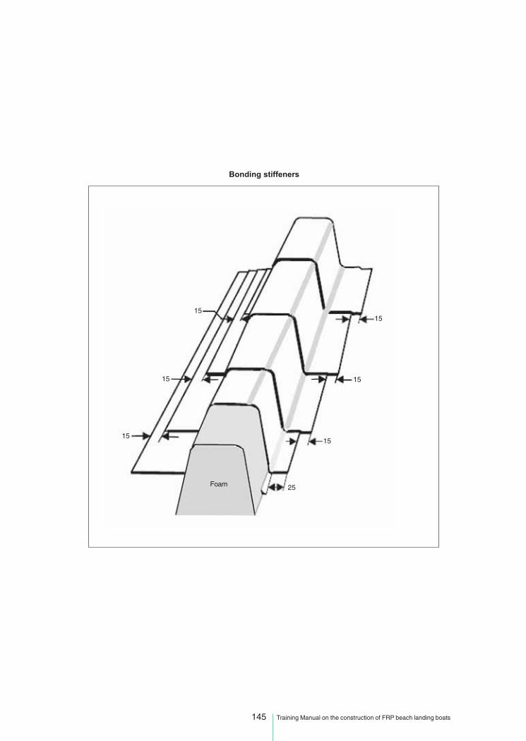
145 Training Manual on the construction of FRP beach landing boats
Bonding stiffeners
15
15
15
25Foam
15
15
15
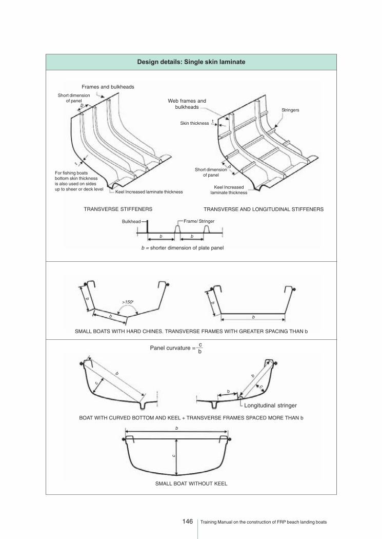
146 Training Manual on the construction of FRP beach landing boats
Design details: Single skin laminate
Frames and bulkheads
Short dimensionof panel
For fishing boatsbottom skin thicknessis also used on sidesup to sheer or deck level
TRANSVERSE STIFFENERS TRANSVERSE AND LONGITUDINAL STIFFENERS
Web frames andbulkheads
Short dimensionof panel
Skin thickness t
Stringers
b
Keel Increasedlaminate thickness
Bulkhead Frame/ Stringer
b b
b = shorter dimension of plate panel
b
b
>150o b
b
SMALL BOAT WITHOUT KEEL
SMALL BOATS WITH HARD CHINES. TRANSVERSE FRAMES WITH GREATER SPACING THAN b
Panel curvature = c b
BOAT WITH CURVED BOTTOM AND KEEL + TRANSVERSE FRAMES SPACED MORE THAN b
c
b
b
b
c
b
c
Longitudinal stringer
Keel Increased laminate thickness

147 Training Manual on the construction of FRP beach landing boats
Stiffeners
Stiffener Spacing
s
t
c
Skin thickness
TRANSVERSE STIFFENERS: Frames and bulkheads TRANSVERSE AND LONGITUDINAL STIFFENERSPRIMARY STIFFENERS: Web frames and bulkheadsSECONDARY STIFFENERS: Longitudinal stiffeners
l - Stiffener span Skin thickness
Transverse web framespacing
s
t
Stiffener Spacings
l
Stiffener unsupportedlength = span
Stiffener Span
ll
ss
Bulkhead
Web frame spacing
TRANSVERSE WEB FRAMES AND LONGITUDINAL STRINGERS
Web frame
Longitudinalstiffener(continuous)
Skin
l U
l
l
>150 o
Transverse framesmust be continuous
across the keel
STIFFENER LENGTH lCHINE ANGLE LESS THAN 150o
STIFFENER LENGTH lCHINE ANGLE MORE THAN 150o
<150 o
l
l
c c
DECKED BOATTRANSVERSE FRAME
SMALL OPEN BOATTRANSVERSE FRAMEKeel and rail are main longitudinal stiffeners
Stiffener curvature = c l
Deck beam length l
l c

148 Training Manual on the construction of FRP beach landing boats
Notes

54 Report of the Fifth Meeting of the Governing Council