
TRAINING CIRCULAR HEADQUARTERS
144
Transcript of TRAINING CIRCULAR HEADQUARTERS


i
*TC 21-24TRAINING CIRCULAR HEADQUARTERSNo. 21-24 DEPARTMENT OF THE ARMY
WASHINGTON, DC, 10 September 1997
RAPPELLING
CONTENTSPage
Preface ......................................................................................................................................viiCHAPTER 1. TOWER RAPPELLINGSection I. Personnel....................................................................................................... 1-2
1-1. Rappel Master ..................................................................................... 1-21-2. Rappel Safety Officer.......................................................................... 1-31-3. Rappel Lane NCO............................................................................... 1-31-4. Rappeller............................................................................................. 1-31-5. Belayer................................................................................................ 1-41-6. Belay Safety........................................................................................ 1-4
Section II. Preoperational Briefings and Safety Procedures............................................. 1-41-7. Safety.................................................................................................. 1-51-8. Safety Briefing .................................................................................... 1-51-9. Tower Safety and Preparation.............................................................. 1-61-10. Rappeller Preparation .......................................................................... 1-7
Section III. Rappelling Procedures................................................................................... 1-81-11. Seat-Hip Rappel .................................................................................. 1-81-12. Australian Rappel.............................................................................. 1-141-13. Climbing Procedures ......................................................................... 1-151-14. Tower Procedures ............................................................................. 1-151-15. Helicopter Skid Rappel...................................................................... 1-181-16. Rappel Tower Training for UH-60 Blackhawk Helicopter ................. 1-191-17. Emergency Lock-In Procedures......................................................... 1-191-18. Communications ............................................................................... 1-201-19. Demonstration................................................................................... 1-20
CHAPTER 2. GROUND RAPPELLING2-1. Personnel............................................................................................. 2-12-2. Sustainment Training .......................................................................... 2-12-3. Selection of a Rappel Point ................................................................. 2-12-4. Establishment of a Rappel Point .......................................................... 2-22-5. Types of Rappels................................................................................. 2-52-6. Rappelling Procedures......................................................................... 2-92-7. Duties of the Rappeller........................................................................ 2-92-8. Belayer.............................................................................................. 2-10
DISTRIBUTION RESTRICTION: Approved for public release; distribution isunlimited.
*This publication supersedes TC 21-24, 24 September 1991.

TC 21-24
ii
PageCHAPTER 3. HELICOPTER RAPPELLINGSection I. Personnel .......................................................................................................3-1
3-1. Rappel Master......................................................................................3-13-2. Rappel Safety Officer ..........................................................................3-13-3. Pilot in Command................................................................................3-13-4. Rappeller .............................................................................................3-23-5. Belayer ................................................................................................3-2
Section II. Training .........................................................................................................3-23-6. Sustainment Training ...........................................................................3-23-7. Refresher Training ...............................................................................3-2
Section III. Preoperational Briefings and Safety Procedures .............................................3-23-8. Medical Coverage................................................................................3-33-9. Communication Requirements .............................................................3-33-10. Adverse Weather/Terrain Conditions ...................................................3-33-11. Night Operation Requirements.............................................................3-33-12. Safety Briefing.....................................................................................3-3
Section IV. Deployment of Ropes ....................................................................................3-43-13. Deployment Bag Technique.................................................................3-43-14. Log Coil Technique .............................................................................3-5
Section V. Rappelling Operations for UH-1H Iroquois Helicopter ..................................3-63-15. Characteristics .....................................................................................3-63-16. Rigging of UH-1H Helicopter for Rappelling.......................................3-63-17. Construction of Anchor Points .............................................................3-73-18. Seating Arrangements and Loading Techniques .................................3-103-19. Rappeling Procedures ........................................................................3-113-20. Rappelling Commands.......................................................................3-113-21. Inspection and Safety Considerations.................................................3-15
Section VI. Rappelling Operations for UH-60 Blackhawk Helicopter.............................3-153-22. Characteristics ...................................................................................3-163-23. Rigging of UH-60 for Rappelling.......................................................3-163-24. Seating Arrangements and Loading Techniques .................................3-183-25. Rappelling Procedures .......................................................................3-193-26. Rappelling Commands.......................................................................3-203-27. Inspection and Safety Considerations.................................................3-20
Section VII. Rappelling Operations for MH-53 Helicopter ..............................................3-213-28. Characteristics ...................................................................................3-213-29. Rigging of MH-53 Helicopter for Rappelling.....................................3-213-30. Seating Arrangements and Loading Techniques .................................3-213-31. Rappelling Procedures .......................................................................3-213-32. Rappelling Commands.......................................................................3-223-33. Inspection and Safety Considerations.................................................3-22
CHAPTER 4. SPECIAL PATROL INFILTRATION/EXFILTRATION SYSTEMSection I. SPIES Master Duties and Qualifications ........................................................4-1
4-1. Qualifications ......................................................................................4-14-2. Duties ..................................................................................................4-1
TC 21-24
iii
Section II. Preoperations Briefings and Procedures......................................................... 4-34-3. Safety.................................................................................................. 4-34-4. Communications ................................................................................. 4-34-5. Extraction Procedures ......................................................................... 4-44-6. Emergency Procedures ........................................................................ 4-44-7. Dismounting Procedures ..................................................................... 4-44-8. Inspection of Equipment...................................................................... 4-54-9. Rigging of UH-1H Helicopter for SPIES Operations ........................... 4-64-10. Rigging of UH-60 Helicopter for SPIES Operations ............................ 4-74-11. Rigging of CH-46/CH-47 Heliocpter for SPIES Operations................. 4-7
Section III. Land and Water Extraction............................................................................ 4-84-12. Land Extraction Procedures................................................................. 4-84-13. Water Extraction Procedures ............................................................... 4-9
Section IV. After-Operations Procedures ....................................................................... 4-104-14. Repairing and Cleaning of Equipment ............................................... 4-104-15. Storage of Equipment........................................................................ 4-10
CHAPTER 5. FAST-ROPE INSERTION AND EXTRACTION SYSTEMSection I. General.......................................................................................................... 5-1
5-1. Objectives ........................................................................................... 5-15-2. Guidance for Commanders .................................................................. 5-15-3. Training Prerequisites.......................................................................... 5-25-4. Personal Equipment Required ............................................................. 5-3
Section II. FRIES Qualification Training........................................................................ 5-35-5. Initial FRIES Qualification Training.................................................... 5-35-6. FRIES Proficiency Sustainment Training ............................................ 5-4
Section III. FRIES Master Selection and Qualification Training ...................................... 5-45-7. FRIES Master Selection ...................................................................... 5-55-8. FRIES Master Prerequisites................................................................. 5-55-9. FRIES Master Training and Certification ............................................ 5-55-10. FRIES Master Refresher Training ....................................................... 5-5
Section IV. Key Personnel Duties and Responsibilities .................................................... 5-55-11. Air Mission Commander ..................................................................... 5-65-12. FRIES Training Officer....................................................................... 5-65-13. Pilot in Command ............................................................................... 5-65-14. FRIES Master ..................................................................................... 5-75-15. FRIES Aircrew Member and Safety .................................................... 5-95-16. FRIES Roper..................................................................................... 5-10
Section V. FRIES Rigging of Aircraft........................................................................... 5-115-17. Rigging of FRIES in UH/MH-60....................................................... 5-115-18. Rigging of FRIES in CH/MH-47....................................................... 5-135-19. Rigging of FRIES in MH-53 ............................................................. 5-14
Section VI. Equipment Maintenance and Inspection....................................................... 5-155-20. Ropes and Harnesses ......................................................................... 5-165-21. FRIES Mount Bars............................................................................ 5-17
Section VII. Operational Requirements and Limitations .................................................. 5-17

TC 21-24
iv
5-22. Medical Support ................................................................................5-175-23. Communications Requirements..........................................................5-185-24. Adverse Weather or Terrain Conditions .............................................5-185-25. Night Operations Requirements .........................................................5-18
Section VIII. FRIES Procedures........................................................................................5-195-26. FRIES Master ....................................................................................5-195-27. Pilot in Command..............................................................................5-205-28. Ropers ...............................................................................................5-215-29. Equipment-Lowering Procedures .......................................................5-215-30. Helicopter Operations FRM Checklist ...............................................5-235-31. FRIES Commands and Signals ..........................................................5-25
Section IX. Emergency Actions......................................................................................5-265-32. Emergencies Before Roping Starts.....................................................5-265-33. Emergencies After Roping Starts .......................................................5-26
Section X. Safety ..........................................................................................................5-275-34. Preflight and Inflight..........................................................................5-275-35. During Roping ...................................................................................5-285-36. Safety Briefing...................................................................................5-285-37. Safety Reminders...............................................................................5-29
CHAPTER 6. EQUIPMENTSection I. Ropes.............................................................................................................6-1
6-1. Types of Ropes ....................................................................................6-16-2. Rope Selection.....................................................................................6-26-3. Care of Ropes ......................................................................................6-36-4. Coiling.................................................................................................6-4
Section II. Snaplinks .......................................................................................................6-56-5. Description ..........................................................................................6-56-6. Types of Snaplinks ..............................................................................6-66-7. Inspection ............................................................................................6-7
Section III. Alternate Methods of Descent ........................................................................6-96-8. Figure-Eight Descender .......................................................................6-96-9. Munter Hitch .......................................................................................6-9
CHAPTER 7. KNOTS7-1. Military Mountaineering Terminology .................................................7-1
Section I. Joining Knots.................................................................................................7-27-2. Square Knot.........................................................................................7-27-3. Double Sheet Bend Knot .....................................................................7-27-4. Fisherman’s Knot ................................................................................7-37-5. Double Fisherman’s Knot ....................................................................7-47-6. Water Knot ..........................................................................................7-5
Section II. Anchor Knots ................................................................................................7-67-7. Bowline Knot ......................................................................................7-67-8. Round Turn and Two Half Hitches Knot..............................................7-77-9. Figure-Eight Retrace Knot ...................................................................7-8
TC 21-24
v
7-10. Clove Hitch Knot ................................................................................ 7-9Section III. Middle Rope Knots ..................................................................................... 7-10
7-11. Wireman’s Knot................................................................................ 7-107-12. Directional Figure-Eight Knot ........................................................... 7-117-13. Bowline-on-a-Bight Knot.................................................................. 7-117-14. Figure-Eight-on-a-Bight Knot ........................................................... 7-127-15. Overhand Loop Knot......................................................................... 7-137-16. Figure-Eight Loop Knot .................................................................... 7-13
Section IV. Special Knots .............................................................................................. 7-147-17. Single Butterfly Knot ........................................................................ 7-147-18. Prusik Knot ....................................................................................... 7-157-19. Bachman Knot .................................................................................. 7-177-20. Bowline-on-a-Coil Knot.................................................................... 7-187-21. Three-Loop Bowline Knot ................................................................ 7-197-22. Figure-Eight Slip Knot ...................................................................... 7-20
Section V. Special-Purpose Knots ................................................................................ 7-217-23. Kleimhiest Knot ................................................................................ 7-217-24. Overhand Knot.................................................................................. 7-227-25. Frost Knot......................................................................................... 7-237-26. Girth Hitch Knot ............................................................................... 7-23
APPENDIX A. RISK ASSESSMENT..................................................................................A-1APPENDIX B. BASIC EQUIPMENT FOR RAPPEL OPERATIONS .................................B-1GLOSSARY ................................................................................................................Glossary-1REFERENCES ........................................................................................................ References-1INDEX..............................................................................................................................Index-1

viii
PREFACE
This circular provides basic rappelling techniques to soldiers and leaders for the conduct ofrappelling operations. It serves as the primary reference for both resident and nonresidentinstruction presented to cadets, officer candidates, and both commissioned andnoncommissioned officers. This circular also discusses several advanced techniques dealingwith infiltration and exfiltration.
Safety is always the most important consideration when conducting training. This circularprovides guidelines for commanders to conduct operations safely. Commanders at all levelsmust analyze the complete training event to determine the degree of risk involved to men andor equipment (Appendix A). After determining the risks, risk reduction options or controlswill be integrated into the training activity. These options or controls may range from a safetybriefing or providing additional safety resources, to selecting other means of accomplishingthe mission.
Rappelling, FRIES, and SPIES operations are inherently dangerous; therefore, the safetynotes and considerations presented in this circular are the minimum acceptable standards.
The proponent of this publication (except for Chapter 5) is the US Army Infantry School.Submit changes for improving this publication on DA Form 2028 and forward it to theCommandant, US Army Infantry School, ATTN: ATSH-RB, Fort Benning, Georgia31905-5593 (e-mail address: [email protected]).
The proponent for Chapter 5, Fast-Rope Insertion/Extraction System, is the US Army SpecialOperations Command. Submit changes or comments for Chapter 5 on DA Form 2028 andforward it to the Commander, US Army Special Operations Command, ATTN: AOOP-TRS,Fort Bragg, North Carolina 28307-5000.
Unless this publication states otherwise, masculine nouns and pronouns do not referexclusively to men.

1-1
CHAPTER 1
TOWER RAPPELLING
The introduction to rappelling is taught on a static tower (Figure 1-1).Using the building block approach to training, soldiers systematicallyprogress to more demanding platforms, including taller static towers, andfinally to helicopters. The static tower used may vary in size and height from34 to 90 feet. The concept of learning the basic rappelling techniques beforehelicopter operations does not vary. (Units may conduct ground training andwall-side tower rappelling without a rappel master. In this case, the unitcommander would be responsible for the safety of the rappelling training.)
Figure 1-1. Rappel tower.
Note: Each static rappel tower should resemble the structure or aircraft being trained to. TheArmy’s standard design for building static rappel towers can be obtained through thePlans and Support Branch of the post Engineers, Building 75, Fort Benning, Georgia31905 (commercial 706 545-3307 or DSN 835-3307). Strict adherence to the designspecifications is required for safety considerations. Rappel towers should be inspectedannually by post safety or post engineers.

TC 21-24
1-2
Section I. PERSONNELThis section discusses the personnel involved in training rappelling and their duties andresponsibilities.
1-1. RAPPEL MASTERThe proponent for accreditation, evaluation, and information for Army rappel master coursesis Directorate of Operations and Training, US Army Infantry School, ATTN: ATSH-OTT-F,Fort Benning, Georgia 31905-5593.
a. Duties and Responsibilities. The rappel master is responsible for the safety ofrappellers. He ensures that all equipment (installation, unit, and personal property) isserviceable. He personally supervises the rappelling operation.
b. Qualification. Rappel master qualification is awarded only after the successfulcompletion of a TRADOC accredited rappel master course, which includes the followingsubjects:
• Duties and responsibilities of a rappel master.• Safety SOP, regulations, and references.• Construction of a deployment bag.• Conduct of an equipment rappel off the rappel tower.• Conduct of a lock-in.• Talking a rappeller through completion of a rappel.• Conduct of ground training.• Inspecting for proper hook-ups.• Inspecting and maintaining equipment.• Inspecting and maintaining snaplinks.• Inspecting and maintaining rappelling gloves.• Inspecting and maintaining rappel ropes.• Identifying the rappel capabilities of aircraft used.• Controlling rappels from UH-1H or UH-60 aircraft.• Tying knots (square, bowline, half-hitch, Prusik), safety lines, and rappel seats (Swiss
seat, Australian seat).• Inspecting a rappel seat.• Aircraft rigging for rappelling operations.• Aircraft command and control.
c. Proficiency Maintenance. To remain current, rappel masters must execute theirduties in a tactical or training exercise once every six months. If rappel masters do not executetheir duties once every six months, they must take a refresher class taught by a current rappelmaster. The refresher class includes the subjects listed in the rappel master qualificationsparagraph (1-1b).

TC 21-24
1-3
1-2. RAPPEL SAFETY OFFICERThe RSO is an air assault-qualified or ranger-qualified SFC or above who serves as the OICfor the conduct of rappel operations.
a. The RSO is responsible overall for the safety of all rappellers and ensures that allsafety precautions are followed.
b. The RSO briefs VIPs, visitors, and inspecting authorities on training, safetyrequirements, and layout of training areas.
1-3. RAPPEL LANE NCOa. Duties and Responsibilities. Safety is the rappel lane NCO’s number one priority.
The rappel lane NCO—
• Ensures proper safety procedures are followed.• Ensures proper hookup once directed to a rope station.• Issues commands and maintains eye contact with the rappeller at all times.
b. Qualifications. The rappel lane NCO holds the rank of corporal or above, is ranger-or air assault-qualified, and is selected by the commander. Each tower rappel lane must havea qualified rappel lane NCO.
c. Training. The rappel lane NCO must also train on the following subjects:
• Responsibilities and safety requirements.• Inspection and maintenance of equipment.• Identification of satisfactory anchor points.• Identification of safe and unsafe hookups.• Establishment of a rappel point.• Inspection of a rappel seat.• Coaching techniques.• Rappelling procedures.• Emergency procedures.• Belay control procedures.
d. Participation. The rappel lane NCO must participate in at least seven rappeloperations: three as a rappeller; two as an assistant rappel lane NCO; and two performing theduties of a rappel lane NCO under the supervision of a qualified rappel master.
e. Proficiency Maintenance. If a rappel lane NCO has not conducted his duties withinthe last six months, he must complete the training listed in paragraph 1-3c under thesupervision of a current rappel master.
1-4. RAPPELLERRappel qualification requirements apply to the individual rappeller. Participants in towerrappel training must complete the following requirements under the supervision of a rappelmaster. The unit commander ensures that personnel successfully complete these requirementsbefore beginning aircraft rappel training.

TC 21-24
1-4
• Identify all rappelling equipment.• Demonstrate the construction and attachment of the rappel seat and the rappel
rope to the seat.• Identify unsafe attachments, equipment, rope connections, and seat construction.• Define terms used in rappelling operations.• Identify knots used in rappel operations.• Understand and demonstrate rappel commands.• Demonstrate rappelling positions.• Demonstrate belaying procedures.• Exhibit satisfactory performance from a rappel tower of at least 34 feet in height
(two rappels with equipment and weapon, two without equipment and weapon).Two rappels are conducted from the free side of the tower (no wall).
• Demonstrate the ability to lock in.
1-5. BELAYERBelay requirements are a subtask of basic rappel requirements. Soldiers must know how tobelay before conducting rappelling training. The belayer—
• Assumes a position at the base of the lane about one pace away from the towerarea.
• Ensures that the rappel ropes are even with the ground during tower rappels.• Loosely holds the rappel rope with both hands so as not to interfere with the
rappeller but still be able to stop the rappeller should he fall.• Immediately stops the rappeller by pulling downward on the rappel ropes if the
rappeller shouts “falling” or loses control of his brake hand during descent.• Does not wear gloves to ensure a firm grip on the rappelling rope.• Watches the rappeller at all times, and maintains constant voice or visual contact.• Wears a helmet to prevent injuries from falling debris.
1-6. BELAY SAFETYThe belay safety must be ranger- or air assault-qualified. He ensures belay personnel areperforming their duties properly. Rappel training requires one belay safety for each two rappelstations.
Section II. PREOPERATIONS BRIEFINGS AND SAFETY PROCEDURESThe rappel master ensures participants have a basic understanding of requirements and safetyprocedures before conducting training.

TC 21-24
1-5
1-7. SAFETYThe following personnel and equipment must be present during static tower training.
• Two military rappel ropes for each rappel station.• One safety officer.• One rappel master for each rappel site.• One rappel lane NCO per rappel station.• One medic with medical kit and backboard.• One safety or medical evacuation vehicle with driver.• One belayer for each rope station. Rappellers alternate stations.• One belay safety for each two rappel stations (four ropes).
1-8. SAFETY BRIEFINGAs in all training, a safety briefing precedes rappel operations. The rappel master briefs allpersonnel on safety to include the following instructions.
a. Each rappeller ensures loose clothing and equipment are secured.b. Rappel seats are tied by the soldier and inspected by the rappel master before climbing
the tower. Rappel seats are removed upon completion of every rappel, retied, and reinspectedby a qualified rappel master or rappel lane NCO before subsequent rappels.
c. Rappellers climb the tower only when directed by the rappel master or rappel laneNCO.
d. Rappellers stay in the center of the tower until instructed to move to a rappel point.e. No more than three personnel are behind each rappelling point.f. If using a troop ladder, only three soldiers are on the ladder at one time. Soldiers do
not climb the ladder until told to do so by a rappel master.g. All rappel masters, rappel lane NCOs, instructors, and anyone else standing near the
edge of the top of the tower must wear a restraining strap or safety rope. The strap or ropemust be attached to an anchor point.
h. No one should lean or sit on the railing or banisters of the tower.i. No one is allowed within 3 feet of the edge of the tower without being secured.j. When attaching the rappel rope to the snaplink, rappellers pull the slack towards the
anchor point. The rappel master or rappel lane NCO physically check each hookup.k. All personnel weighing more than 200 pounds will conduct a standard hookup rappel
to determine if they require a friction hookup. A friction hookup is created by placing anadditional two ropes in the gate of the snaplink (for a total of six ropes in the snaplink).
l. Combat equipment is positioned on the rappeller so that it does not interfere with thebrake hand. The weapon must be slung diagonally across the back with the muzzle pointingdown, and on the opposite side of the brake hand.
m. Heavy duty gloves are required for all rappel training.n. Kevlar helmets with chin straps fastened are worn during tower rappel training.o. While on the tower, the rappeller maintains eye contact with the rappel master or
rappel lane NCO and receives all commands from them.p. The rappeller ensures that he has a belayer on his rope.q. The belayer does not wear gloves and keeps both hands on the rope at all times. He
also faces the rappeller at all times.
TC 21-24
1-6
r. All tower rappelling is performed with a double strand of rope.s. No running is allowed on the tower.t. No smoking or eating is allowed near the tower.u. All participants who are unable to rappel, lack confidence, or refuse to rappel are
reported to the rappel master or OIC. These participants are immediately removed from thetraining area.
v. The RSO and rappel master must be aware of overconfidence and carelessness ofsome rappellers. The rappel master ensures all personnel are tower-qualified before beginningaircraft rappel training.
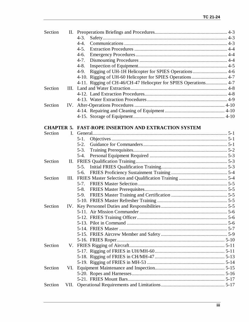
1-9. TOWER SAFETY AND PREPARATIONThe rappel master is in charge of the tower. He conducts a visual and physical inspection ofevery item of equipment to include the structural lumber and timber, the ladder, the platformfloor, and all anchor points.
a. The static tower will not be used during thunderstorms or excessively high winds. Ifice is present, or if the platform is slick from rain, rappelling will be delayed until conditionsare safe.
A B
Figure 1-2. Example of rappel tower anchor points.
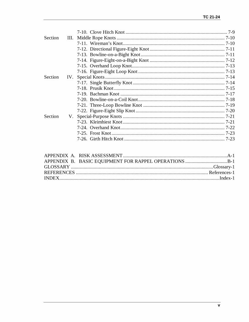
b. All rope stations are rigged with two anchor points (Figure 1-2A, B, C). The firstanchor point is a middle-of-the-rope knot, and the second is an end-of-the-rope anchor knot.The rappel master removes all the slack between the knots to createequal tension on the anchor points. He ensures that no less than 10 feet of rope is on theground during static rappelling.
TC 21-24
1-7
C
Figure 1-2. Example of rappel tower anchor points (continued).
1-10. RAPPELLER PREPARATIONBefore conducting a rappel, each rappeller must prepare his individual clothing andequipment.
WARNINGFailure to properly prepare rappellers could result in bodilyinjury or damage to equipment.
a. Secure shirt tails, loose clothing, equipment, straps, and long hair.b. Wear a helmet during rappelling. Properly fasten all straps and ensure the helmet is
in serviceable condition.c. Wear heavy leather workman’s gloves.d. Wear identification tags.e. When rappelling with equipment, LBE or LBV should be unfastened in the front or
fastened loosely behind the back of the rappeller. The rucksack should be worn high and tighton the back of the rappeller to allow the brake hand to reach the small of the back. Rucksackadjustment straps will be tied across the chest or tucked away.
f. Sling the weapon diagonally across the back with the muzzle down. Ensure the muzzleis on the guide hand side and the stock is towards the brake hand.
Note: Soldiers rappelling with equipment in excess of 50 pounds may want to consider usinga friction hookup.

TC 21-24
1-8
Section III. RAPPELLING PROCEDURESThis section discusses procedures used in tower rappelling.
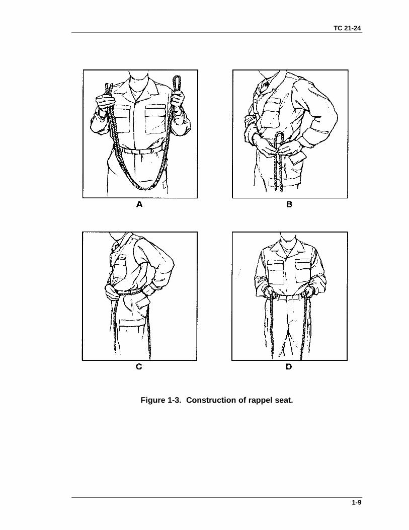
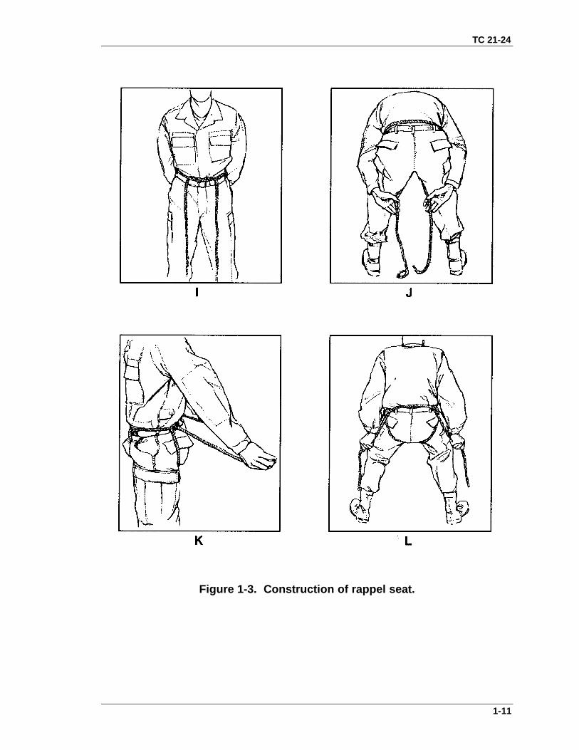
1-11. SEAT-HIP RAPPELWhen using the seat-hip rappel, friction is created by a snaplink that is inserted in a sling ropeseat and fastened to the rappeller. This method provides a faster and more controlled descentthan other methods. Wear gloves to prevent rope burns. An alternate technique is to inserta second snaplink into the first snaplink (attached to rappel seat) and run the rope through thesecond snaplink. This allows easier disengagement from the rappel rope without running theentire rope through the first snaplink. To disengage from the rappel rope using the alternatetechnique, release the tension from the rope by opening the gate of the first snaplink andremoving the second snaplink (with the rope attached).
a. The rappel seat is constructed as follows (Figure 1-3A through 1-3T):(1) Place the midpoint (center) of the length of the sling rope on the hip opposite the
brake hand (the brake hand is the strong hand) (Figure 1-3A, B, C).(2) Bring the sling rope around the waist above the hip bone. Tie a double overhand knot
over the navel (Figure 1-3D, E, F, G, H).(3) Let the two free ends of the sling rope fall to the ground in front (Figure 1-3I).(4) Bring the two free ends of the sling rope down between the legs and up over the
buttocks. Ensure that the two free ends do not cross (Figure 1-3J).(5) Pass the ends of the ropes over the rope that is tied around the waist at the two points
above the center of the two rear seat pockets (Figure 1-3K).(6) Grab the free end of the rope that is on the left side of the body with the left hand, and
the free end of the rope that is on the right side of the body with the right hand.(7) Squat down and simultaneously pull on both running ends of the ropes and stand up.
This will tighten the seat.(8) Take the two running ends of the rope down and back over the waist rope from the
inside. Bring the running ends back under the ropes that are going across the buttocks (Figure1-3L).
(9) Tie the two running ends with a square knot and two overhand knots on the hipopposite the brake hand (Figure 1-3M, N).
(10) Place any excess rope in the trouser pocket near the square knot (Figure 1-3O, P).(11) With the gate down and the hooked end of the snaplink against the navel, place
the end of the snaplink through the single rope that is around the waist and the two ropesforming the double-hand knot (Figure 1-3Q).
(12) Rotate the snaplink a half turn so that the gate is facing up and will open awayfrom the body (Figure 1-3R, S, T).
TC 21-24
1-9
Figure 1-3. Construction of rappel seat.

TC 21-24
1-10
Figure 1-3. Construction of rappel seat.
TC 21-24
1-11
Figure 1-3. Construction of rappel seat.

TC 21-24
1-12
Figure 1-3. Construction of rappel seat.

TC 21-24
1-13
Figure 1-3. Construction of rappel seat.
b. To hook up using the seat-hip method, perform the following:(1) Place the square knot with two overhand knots towards the anchor point for all seat-
hip rappels.(2) Grasp the two ropes with both hands and drop them through the gate of the snaplink.
(At this point, two ropes should be running through the snaplink.)

TC 21-24
1-14
(3) Using the hand closest to the anchor point, pull the slack towards the anchor point.Rotate the slack under and then over the top of the snaplink.
(4) Drop the two ropes a second time through the gate of the snaplink. (At this point, fourropes should be running through the snaplink.)
(5) Place the guide hand on the rope between the anchor point and the snaplink (palmfacing up).
(6) Place the brake hand around the running end of the rope (palm facing down). Placethe brake hand with the rope in the small of the back.
1-12. AUSTRALIAN RAPPELTo hook up for the Australian rappel (Figure 1-4), perform the following:
a. Hook up to the Australian seat.(1) Grasp the 9-foot sling rope at the midpoint (center) of its length, and double the rope.(2) Place the doubled sling rope around the back and waist. Ensure that the rope is above
the hipbone, but below the ribs.(3) Tie a square knot with two overhand knots over the navel.(4) Place any excess rope in the trouser pocket nearest the excess.b. When the Australian seat is donned, face away from the anchor point and to the side
of the rappel rope. (Stand to the same side of the rope as the brake hand. Determine left andright of the rope while facing the anchor point.) Place a snaplink onto the seat with the gatefacing up, hinge closest to the body. Place it on the hip corresponding to the brake hand. Therappel master grasps the rappel rope and lays the rope into the snaplink. He then places onehand between the snaplink and the anchor point and draws slack toward the anchor point. Herotates the slack down, under, and over the rope and into the snaplink. The rappel master thenslides the snaplink directly to the rappellers back.
c. Serve the running end of the rappel rope with the brake hand and prepare to rappel.During descent, brake by drawing the rappel ropes diagonally across the chest with the ropesrunning from near the waist to the pocket of the opposite shoulder.
Figure 1-4. Australian rappel.

TC 21-24
1-15
1-13. CLIMBING PROCEDURESBefore climbing the ladder, the rappel master, safety OIC, or rappel lane NCO checks eachrappeller’s equipment.
a. The rappeller kicks the sand off his boots before climbing.b. The rappeller grasps the outside of the ladder while climbing, not the rungs (when
possible). If stairs are built for the tower, the rappeller grasps the railings as appropriate.c. Just before climbing up the ladder, the rappeller sounds off, “(name) climbing,” and
then begins climbing up the ladder. Once at the top and clear of the ladder, the rappellersounds off, “(name) clear.”
d. Once off the ladder, the rappeller waits until the rappel master or lane NCO directshim to proceed to a rope station. At this time, the next rappeller in line may start to climb theladder.
1-14. TOWER PROCEDURESAfter the rappellers climb the tower, the following procedures are adhered to:
a. Once directed to a rope station, the rappel master or lane NCO ensures proper hookupfor rappelling.
b. At this time, the rappeller sounds off with “on rappel” and the belayer sounds off with“on belay.”
c. While maintaining his brake, the rappeller (on command from the rappel master orlane NCO) steps over the safety rail and faces the anchor point.
d. At this point, the rappel lane NCO sounds off with the following verbal commands andarm-and-hand signals.
(1) Get Ready— Rappel master or lane NCO extends both arms to the front with fistsclenched and thumbs pointing upward (Figure 1-5). This alerts the rappeller. Each rappellerthen looks over his brake hand shoulder to check for the belay man. The rappeller then looksat the rappel master. The rappel master or lane NCO makes his second check of the hookup,rappel seat, snaplink, and equipment.
Figure 1-5. Example of arm-and-hand signal GET READY.

TC 21-24
1-16
(2) Position— The lane NCO extends both arms to the front, elbows locked, forearmspointed downward, and fingers extended. He makes a circular motion with both forearmsrotating in opposite directions (Figure 1-6). With the brake hand in the small of the back, therappeller rotates 180 degrees out onto the wall or skid mock up and assumes an L-shapedposition. The feet should be shoulder width apart, balls of feet on the wall or skid, kneeslocked, and body bent at the waist (Figure 1-7).
Figure 1-6. Example of arm Figure 1-7. L-shape position. and hand signal POSITION.
(3) Go— The lane NCO extends his right arm with the elbow locked, fingers extended,thumbs around the index fingers, and points directly at the rappeller (Figure 1 8). Thisinitiates the rappel. The rappeller flexes his knees and jumps vigorously backwards. At thesame time, the rappeller throws his brake hand out at a 45-degree angle, letting the ropeslide through both the brake hand and the guide hand. The rappeller looks over his brakehand shoulder at all times during descent.
Figure 1-8. Example of arm-and-hand signal GO
e. The rappeller descends in a smooth, controlled manner.f. The rappeller maintains eye contact with the ground at all times.g. The rappeller maintains a modified L-shape position during descent with the feet
shoulder-width apart, knees flexed, and buttocks parallel to the ground (Figure 1-9).

TC 21-24
1-17
Figure 1-9. L-shape position while rappelling.
h. When carrying equipment or additional weight, a modified L-shape is used with thelegs slightly lower than the buttocks to compensate for the added weight.
i. The rappeller’s back is straight. He looks over the brake hand shoulder.j. The guide hand is extended on the rope with the elbow extended and locked.k. The rope slides freely through the guide hand, which is used to adjust equipment and
to assist in balance during descent.l. To brake, the rappeller places the brake hand (with rope in hand) in the small of the
back and then grasps the rope firmly with the brake hand.
Note: Do not grip the rope firmly with the brake hand while the brake hand and brake armare extended at the 45-degree angle. If this is done while rappelling, the brake handand glove may become entangled in the snaplink causing injury to the hand andcausing the rappeller to become hung up on the ropes.
m. Releasing tension on the rope and moving the brake hand out to the rear at a45-degree angle regulates the rate of descent.
n. The rappeller never lets go of the rope with his brake hand until the rappel iscompleted.
o. After the rope is cleared and the rappeller is off rappel, he acts as the belayer for thenext rappeller.
1-15. RAPPEL TOWER TRAINING FOR UH-1H HELICOPTERTraining on the rappel tower for helicopter skid rappelling prepares soldiers to rappel froma UH-1H helicopter (Figure 1-10). The rappeller is hooked up while he sits on the platformjust above the helicopter skid. On the rappel master’s command GET READY, the rappellerlooks over the edge of the tower to ensure the running ends of the ropes are on the ground(Figure 1-10A). On the command SIT IN THE DOOR, the rappeller rotates his feet and legsoff the platform and places them on the skid (Figure 1-10B). On the command POSITION,the rappeller turns around and assumes an L-shape position (Figure 1-10C). On the commandGO, the

TC 21-24
1-18
rappeller bounds away from the helicopter skid and rappels to the ground. The rappel masteris responsible for the proper procedures and safety.
A B C
Figure 1-10. UH-1H helicopter skid rappel training.1-16. RAPPEL TOWER TRAINING FOR UH-60 BLACKHAWK HELICOPTERRappel tower training for the UH-60 Blackhawk is similar to that for the UH-1H with theexception that the UH-60 has no skids on which to stand. Therefore, the edge of the rappeltower is used as a pivot point to assume the L-shape position. All commands are the sameexcept for SIT IN THE DOOR, which does not apply to the UH-60. The stances for eachcommand are also different, as shown in Figure 1-11.
A B
Figure 1-11. UH-60 helicopter rappel training.
1-17. EMERGENCY LOCK-IN PROCEDURESMastering the lock-in procedure during tower training is critical before advancing tohelicopter rappelling. Using the lock-in procedure allows personnel to hold in position for anextended period of time.

TC 21-24
1-19
a. If the helicopter gains altitude above the length of the rappel ropes, the rappellerimmediately brakes, locks in, and waits for the descent of the aircraft. Procedures for lock-inare as follows:
(1) Place the brake hand in the small of the back and brake to a complete stop.(2) Release the guide hand from the ropes.(3) Bring the guide hand around the back and grasp the running end of the two rappel
ropes behind the brake hand.(4) Using the guide hand, bring the two running ends of the rappel ropes around to the
front.(5) Secure these two running ends of the rappel ropes with the two anchor ends of the
rappel ropes in the guide hand. This is now the new brake hand.(6) Take the old brake hand out of the small of the back. Bring it around to the front and
grasp the two ropes from the anchor point at a point just above the new brake hand. The oldbrake hand is now the new guide hand.
(7) Face the rappel master and wait for his command to lower to the ground.(8) When the command is received from the rappel master to continue the descent, bring
the brake hand to a 45-degree angle to the rear. When it is time to brake, bring the new brakehand around to the front diagonally across the chest.
b. If an engine fails or an aircraft emergency occurs during rappelling, the rappellers onthe ropes descend as rapidly as possible and move from beneath the aircraft to the sides.Rappellers will maintain control of ropes, if possible.
1-18. COMMUNICATIONSThe rappeller at the top of a rappel point must be able to communicate with those at thebottom. Radios, hand signals, and rope signals are considered during a tactical rappel. Fortraining situations, use the following commands:
COMMAND GIVEN BY MEANINGLANE NUMBER, ON RAPPEL Rappeller I am ready to begin
rappelling.LANE NUMBER, ON BELAY Belayer I am on belay and you
may begin your rappel.LANE NUMBER, OFF RAPPEL Rappeller I have completed the
rappel, cleared therappel lane, and am offthe rope.
LANE NUMBER, OFF BELAY Belayer I am off belay.LANE NUMBER, FALLING Rappeller I am falling. Be alert
below— belay man brake.
1-18. DEMONSTRATIONAfter explaining the procedures to all rappellers, the rappel master should have an assistantdemonstrate one complete cycle of rappelling from the static tower. This ensures that the

TC 21-24
1-20
rappellers can hear all the proper commands and see the actions and techniques used on thestatic tower.

2-1
CHAPTER 2
GROUND RAPPELLING
Ground rappelling is a technique that allows soldiers to negotiatemountains and cliffs safely and rapidly. Before rappellers participate inmountain and cliff rappelling they should have completed all therequirements for tower training. To ensure the rappel is safely conductedand meets the mission requirements, rappellers should consider severalfactors.
2-1. PERSONNELThe personnel responsibilities for mountain and cliff rappelling are the same as for towerrappelling. As a minimum the following personnel are needed for mountain and cliffrappelling.
a. Mountaineering Safety Officer (MSO). The MSO is a SFC or above who isranger qualified or is a graduate of the Northern Warfare Training Center (NWTC). Hehas overall responsibility for the safety of all mountaineering participants and ensuresthat all safety precautions are followed.
b. Rappel Master. The rappel master is a qualified officer or NCO in charge oftraining on ground, tower, and aircraft rappel safety procedures.
c. Medical Officer or Noncommissioned Officer. Qualified rappellers and aidmenmust know MEDEVAC procedures.
d. Radiotelephone Operator. The RATELO monitors the radio and reports to theRSO.
e. Rappel Lane NCO. The rappel lane NCO is a qualified officer or NCO in chargeof rappelling on a wall or ground rappel lane (Chapter 1, paragraph 1-3).
2-2. SUSTAINMENT TRAININGBefore conducting ground rappel training, the unit or element conducts sustainmenttraining.
a. Review the construction of a rappel seat, seats to be used, and hook-upprocedures.
b. Conduct two rappels on the 34-foot tower wall (20-foot tower is acceptable): onewith equipment, one without equipment. Conduct two rappels from the free side of a 34-foot or higher rappel tower.
c. Demonstrate the ability to lock in during one of the rappels from the free side ofthe tower.
2-3. SELECTION OF A RAPPEL POINTThe selection of the rappel point depends on factors such as mission, cover, route, anchorpoints, and edge composition (loose or jagged rocks). The anchor point should be abovethe rappeller’s departure point. Primary and secondary anchors must be solid (naturalanchors are preferred). The rappeller should be sure that the rope reaches the bottom or aplace from which he can further rappel or climb. Also, the rappel point should becarefully tested and inspected to ensure the rope will run freely and that the area is clear

TC 21-24
2-2
of obstacles that could be dislodged. If a sling or runner is used for a rappel point, itshould be tied twice from two separate loops. Suitable loading and off-loading platformsshould be available.
2-4. ESTABLISHMENT OF A RAPPEL POINTA rappel lane is the area and rope that a rappeller will use during his descent. It shouldhave equal tension between all anchor points by establishing primary and secondaryanchor points (Figure 2-1). If one anchor point fails, the rappel rope should not extend.All of the methods discussed below can be performed with a single or double rope. Adouble rope application should be used for safety.
Figure 2-1. Rappel point.
a. If a rappel lane is less than half the rope length, the rappeller may apply one of thefollowing techniques:
(1) Double the rope and tie a three-loop bowline around the primary anchor toinclude the primary anchor inside two loops and enough rope in the third loop to run tothe secondary anchor (another three-loop bowline secured with an overhand knot).
(2) Double the rope and tie it around a secure anchor point with a round turn anchorbowline secured with an overhand knot (or any appropriate anchor knot).
(3) Double the rope and establish a self-equalizing anchor system (Figure 2-2) with abowline-on-a-bight or figure-eight-on-a-bight knot. Tie off on the long standing and witha round turn anchor bowline.

TC 21-24
2-3
Figure 2-2. Self-equalizing anchor system.
(4) In an emergency, double the rope and place it behind or through a secure anchorpoint, or tie a runner around an anchor point with a snaplink inserted and place the ropethrough the snaplink. To preclude a rappeller from sliding off the end of the rappel lane,tie a double figure eight (square knot or double fisherman’s knot) at the bottom end of therope with both ends.
b. If a rappel lane is greater than half the rope length, the rappeller may apply one ofthe following techniques:
(1) Using two ropes, tie a round turn anchor bowline around a primary anchor point.Take the remaining rope (the tail from the primary anchor bowline) and tie another roundturn anchor bowline to a secondary anchor point. The secondary anchor point should bein a direct line behind the primary anchor point. The anchor can be either natural orartificial. The ends of the rappel lane ropes should be offset by 15 centimeters (6 inches)so that the rope ends feed freely through the rappeller’s snaplink.
(2) Using two ropes, establish a three-piton anchor system using a bowline-on-a-bightknot (or figure-eight-on-a-bight knot) and tie off on the long-standing end with a roundturn anchor bowline.
(3) In an emergency, use two ropes and tie the two ends together with a joining knot.Place the joined ropes behind or through an anchor point, or tie a runner around ananchor point with a snaplink inserted and place the joined rope through the snaplink.Offset the joining knot to the left or right of the anchor. Tie off the bottom end of the ropewith a joining knot to prevent a rappeller from sliding off the end of the rappel line.
c. Due to the length of the rappel, the rappel rope may not reach the anchor. If therope is used to tie the knots, it may be too short to accomplish the rappel.
(1) When using a natural anchor—(a) Tie a sling rope, runner, or another rope around the anchor with a round turn
anchor bowline.(b) Tie a fixed loop (figure eight or butterfly) in one end of the rappel rope, which is
attached to the round turn around the anchor through the two snaplinks (opposing gates).(2) When using an artificial anchor—(a) Tie off a sling rope, runner, or another rope to form a loop.(b) Put the loop through the snaplinks that are attached to the artificial anchor point.

TC 21-24
2-4
(c) Bring the bottom of the loop up and connect it to the snaplinks that are betweenthe artificial anchors (chocks, pitons, or bolts).
(d) Grasp the snaplinks that are between the chocks/pitons and pull them down andtogether.
(e) Tie a fixed loop (figure eight or butterfly) in the end of the rappel rope andconnect this to the snaplinks that have been pulled together.
Notes: 1. Rerouted figure-eight knots can be used instead of bowlines.2. Runners may be used from one or more anchor points.
d. Backfeed (stack) the rope to ensure it does not snarl when thrown. Take off onewrap at a time and let it fall to the ground, ensuring that no kinks, knots, or twists occurthat might hinder the rope from feeding out. When the rope is backfed, anchor off oneend of the rope. The two methods used to throw the rope are underhand and overhand.Use the overhand method when trees or shrubs are on or near the rappel point.
e. Set up a retrievable rappel point by applying one of the following techniques:(1) When the rappel is less than half the total length of the rope, double the rope.
Place the rope around the primary anchor with the bight formed by the midpoint. Join thetails of the rappel rope and throw the rope over the cliff. Tie a clove hitch knot around asnaplink just below the anchor point ensuring the locking bar inside the snaplink pointsaway from the gate opening end and faces uphill. Snap the opposite standing portion intothe snaplink. Upon reaching the bottom of the cliff, pull on the part of the rope to whichthe snaplink is secured to allow the rope to slide around the anchor point.
(2) When the length of the rappel is greater than half the length of the rope used, jointwo ropes around the anchor point (double fisherman’s knot or square knot). Adjust thejoining knot so that it is away from the anchor. Tie a clove hitch knot around a snaplinkjust below the anchor point ensuring the locking bar inside the snaplink points away fromthe gate opening end and faces uphill. Snap the opposite standing portion into thesnaplink. Upon completion of the rappel, pull the rope to which the snaplink is secured toallow the rope to slide around the anchor point.
WARNINGWhen setting up a retrievable rappel using only a primarypoint, take care in selecting the point. Ensure soldiers havea safety line when approaching the rappel point, with onlythe rappeller going near the edge.
2-5. TYPES OF RAPPELSTypes of rappels include body rappel, hasty rappel, seat-hip rappel, seat-shoulder rappel,Australian rappel, and buddy-evacuation. (Seat-hip rappel and Australian rappel aredescribed in Chapter 1, paragraphs 1-10 and 1-11.)
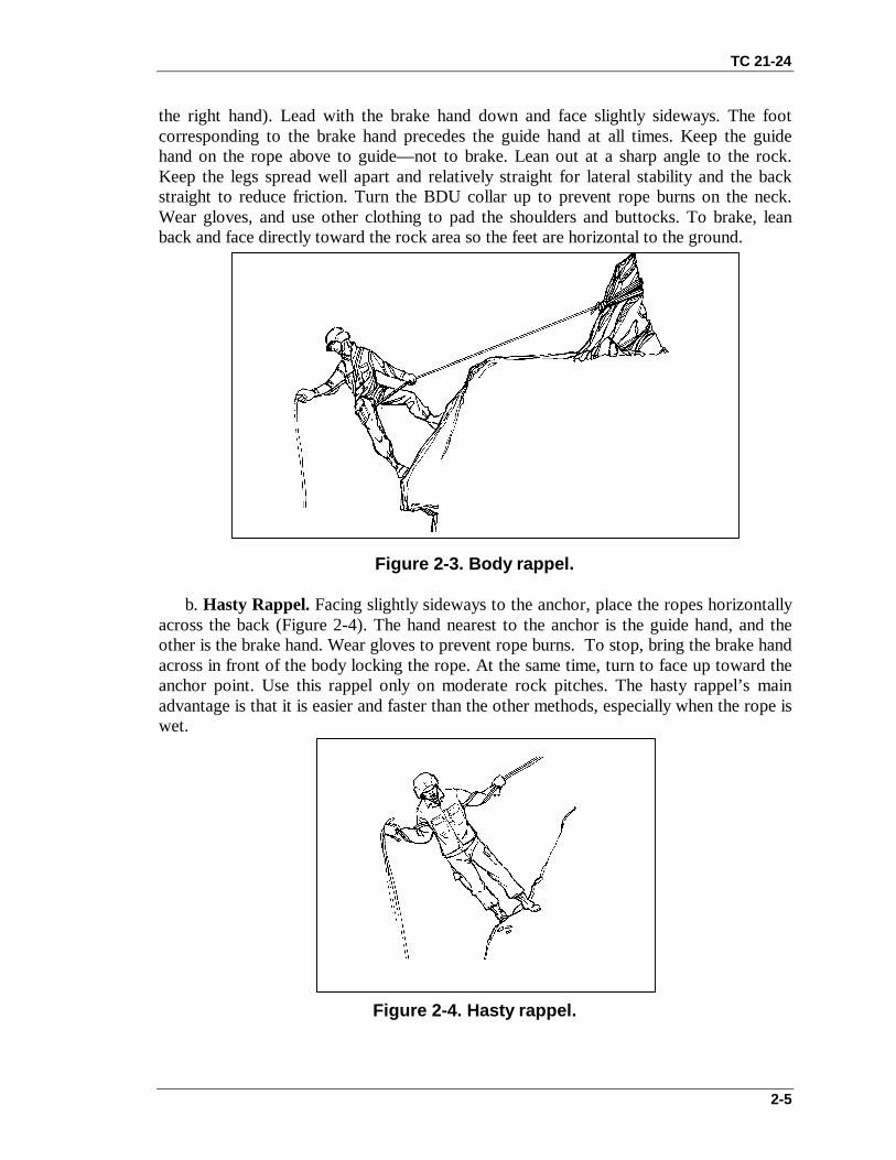
a. Body Rappel. Face the anchor point and straddle the rope. Pull the rope frombehind and run it around either hip, diagonally across the chest, and back over theopposite shoulder (Figure 2-3). Then, run the rope to the brake hand, which is on thesame side of the hip that the rope crosses (for example, the right hip to the left shoulder to
TC 21-24
2-5
the right hand). Lead with the brake hand down and face slightly sideways. The footcorresponding to the brake hand precedes the guide hand at all times. Keep the guidehand on the rope above to guide— not to brake. Lean out at a sharp angle to the rock.Keep the legs spread well apart and relatively straight for lateral stability and the backstraight to reduce friction. Turn the BDU collar up to prevent rope burns on the neck.Wear gloves, and use other clothing to pad the shoulders and buttocks. To brake, leanback and face directly toward the rock area so the feet are horizontal to the ground.
Figure 2-3. Body rappel.
b. Hasty Rappel. Facing slightly sideways to the anchor, place the ropes horizontallyacross the back (Figure 2-4). The hand nearest to the anchor is the guide hand, and theother is the brake hand. Wear gloves to prevent rope burns. To stop, bring the brake handacross in front of the body locking the rope. At the same time, turn to face up toward theanchor point. Use this rappel only on moderate rock pitches. The hasty rappel’s mainadvantage is that it is easier and faster than the other methods, especially when the rope iswet.
Figure 2-4. Hasty rappel.

TC 21-24
2-6
Figure 2-5. Seat-shoulder rappel.
c. Seat-Shoulder Rappel. To hook up for the seat-shoulder method, face the rappelpoint (Figure 2-5). Snap into the rope that passes up through the snaplink. Bring the ropeover one shoulder and back to the opposite hand (left shoulder to right hand). Use thesame technique in the descent as in the body rappel. This method is faster than the bodyrappel, less frictional, and more efficient rappellers with packs and during nightoperations.
d. Buddy-Evacuation Rappel. Use the buddy-evacuation rappel to evacuate aninjured soldier from a cliff or steep terrain. Face the cliff and assume a modified L-shapebody position to compensate for the weight of the victim on the back. The victim is top-rope belayed from above, which provides the victim with a point of attachment to asecured rope.
Note: To use this rappel, the victim must be conscious.
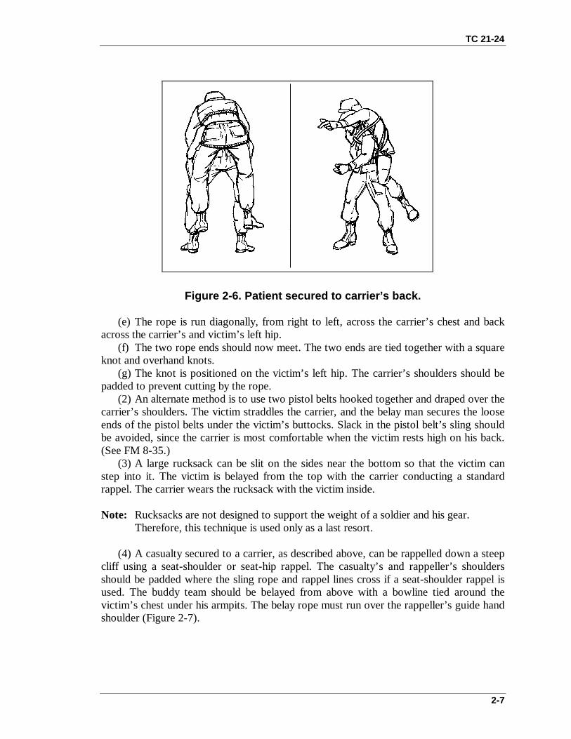
(1) The method for securing a victim to a rappeller’s back is described below:(a) To secure the victim to the carrier’s back with a rope, the carrier ties a standard
rappel seat (brake of choice, depending on the injury) and rests his hands on his kneeswhile the victim straddles his back (Figure 2-6.)
(b) A 4.2-meter (14-foot) sling rope is used. A 45-cm (18-inch) tail of the sling isplaced on the victim’s left hip. (This method describes the procedure for a seat-hip rappelwith right-hand brake.)
(c) The long remaining end of the sling rope is routed under the victim’s buttocks andpassed over the victim’s and carrier’s right hip. The rope is run diagonally, from right toleft, across the carrier’s chest, over his left shoulder, and back under the victim’s leftarmpit.
(d) The rope is then run horizontally, from left to right, across the victim’s back. Therope is passed under the victim’s right armpit and over the carrier’s right shoulder.
TC 21-24
2-7
Figure 2-6. Patient secured to carrier’s back.
(e) The rope is run diagonally, from right to left, across the carrier’s chest and backacross the carrier’s and victim’s left hip.
(f) The two rope ends should now meet. The two ends are tied together with a squareknot and overhand knots.
(g) The knot is positioned on the victim’s left hip. The carrier’s shoulders should bepadded to prevent cutting by the rope.
(2) An alternate method is to use two pistol belts hooked together and draped over thecarrier’s shoulders. The victim straddles the carrier, and the belay man secures the looseends of the pistol belts under the victim’s buttocks. Slack in the pistol belt’s sling shouldbe avoided, since the carrier is most comfortable when the victim rests high on his back.(See FM 8-35.)
(3) A large rucksack can be slit on the sides near the bottom so that the victim canstep into it. The victim is belayed from the top with the carrier conducting a standardrappel. The carrier wears the rucksack with the victim inside.
Note: Rucksacks are not designed to support the weight of a soldier and his gear.Therefore, this technique is used only as a last resort.
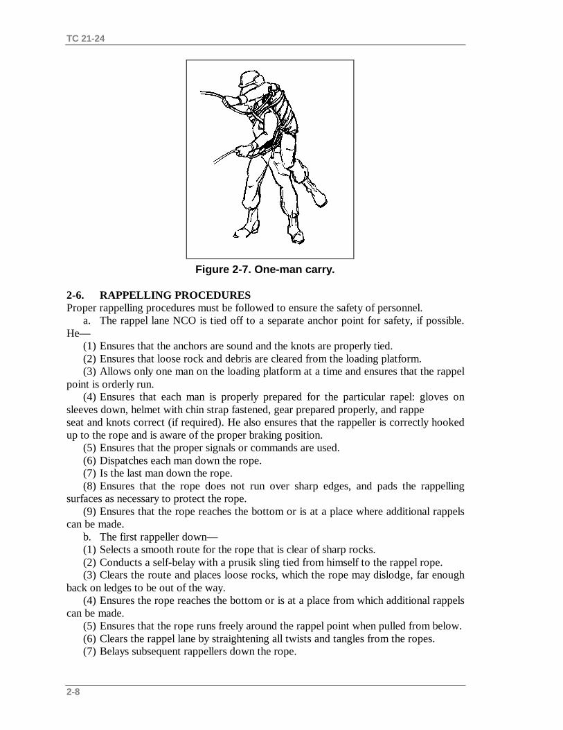
(4) A casualty secured to a carrier, as described above, can be rappelled down a steepcliff using a seat-shoulder or seat-hip rappel. The casualty’s and rappeller’s shouldersshould be padded where the sling rope and rappel lines cross if a seat-shoulder rappel isused. The buddy team should be belayed from above with a bowline tied around thevictim’s chest under his armpits. The belay rope must run over the rappeller’s guide handshoulder (Figure 2-7).
TC 21-24
2-8
Figure 2-7. One-man carry.
2-6. RAPPELLING PROCEDURESProper rappelling procedures must be followed to ensure the safety of personnel.
a. The rappel lane NCO is tied off to a separate anchor point for safety, if possible.He—
(1) Ensures that the anchors are sound and the knots are properly tied.(2) Ensures that loose rock and debris are cleared from the loading platform.(3) Allows only one man on the loading platform at a time and ensures that the rappel
point is orderly run.(4) Ensures that each man is properly prepared for the particular rapel: gloves on
sleeves down, helmet with chin strap fastened, gear prepared properly, and rappeseat and knots correct (if required). He also ensures that the rappeller is correctly hookedup to the rope and is aware of the proper braking position.
(5) Ensures that the proper signals or commands are used.(6) Dispatches each man down the rope.(7) Is the last man down the rope.(8) Ensures that the rope does not run over sharp edges, and pads the rappelling
surfaces as necessary to protect the rope.(9) Ensures that the rope reaches the bottom or is at a place where additional rappels
can be made.b. The first rappeller down—(1) Selects a smooth route for the rope that is clear of sharp rocks.(2) Conducts a self-belay with a prusik sling tied from himself to the rappel rope.(3) Clears the route and places loose rocks, which the rope may dislodge, far enough
back on ledges to be out of the way.(4) Ensures the rope reaches the bottom or is at a place from which additional rappels
can be made.(5) Ensures that the rope runs freely around the rappel point when pulled from below.(6) Clears the rappel lane by straightening all twists and tangles from the ropes.(7) Belays subsequent rappellers down the rope.

TC 21-24
2-9
(8) Takes charge of personnel as they arrive at the bottom (off-loading platform).
Note: A rappeller is always belayed from the bottom except for the first man down. Thefirst man belays himself down the rope by using a safety line attached to hisrappel seat that is hooked to the rappel rope with a prusik knot. As the first manrappels down the rope, he “walks” the prusik knot down with him.
2-7. DUTIES OF THE RAPPELLERTo ensure the safe and efficient conduct of rappelling operations, each rappeller mustknow the duties of his job.
a. Each rappeller down shouts, “Off rappel” (if the tactical situation permits),untangles the ropes, and ensures the ropes run freely around their anchors. When silenceis needed, a planned signal of pulling the rope is substituted for the voice signal. After therope is cleared and the rappeller is off rappel, he acts as the belayer for the next rappeller.
b. All rappellers inspect ropes often when many soldiers are rappelling.c. The last rappeller to descend constructs a retrievable rappel point and rappels
down. Then he gently pulls the rope to prevent the rising rope end from entangling withthe other rope. He stands clear of the falling rope and any rocks that it may dislodge.
Note: Soldiers wear gloves for all types of rappels for protection from rope burns. Also,bounding rappels are discouraged since this stresses the anchor and causes unduewear and friction on the rope.
d. Rappellers descend in a smooth, controlled manner. The body forms an L-shapewith the feet shoulder-width apart, legs straight, and buttocks parallel to the ground.When carrying equipment or additional weight, a modified L-shape is used with the legsslightly lower than the buttocks to compensate for the added weight. The rappeller’s backis straight. He looks over the brake shoulder. The guide hand is extended on the rope withthe elbow extended and locked. The rope slides freely through the guide hand, which isused to adjust equipment and to assist balance during the descent. The rappeller graspsthe rope firmly with the brake hand and places it in the small of his back. Releasingtension on the rope and moving the brake hand out to his rear at a 45-degree angleregulates the rate of descent. The rappeller never lets go of the rope with his brake handuntil the rappel is completed.
e. During training, the lane number must be understood. In combat, a series of tugson the rope may be substituted for the oral commands to maintain noise discipline. Thenumber of tugs used to indicate each of the commands is IAW the unit SOP.
2-8. BELAYERThe belayer assumes a position at the base of the lane about one pace away from the rockarea. He ensures that the rappel ropes are even with the ground during rock and towerrappels. The belayer loosely holds the rappel ropes with both hands so as not to interferewith the rappeller but still able to stop the rappeller should he fall. If the rappeller shouts“Falling” or loses control of his brake hand or descent, the belayer immediately stops therappeller by pulling downward on the rappel ropes. To ensure a firm grip on therappelling rope, the belayer does not wear gloves. (Because no friction exists between the

TC 21-24
2-10
belayer’s hands and the rappelling rope, gloves are not required for safety. However,whether or not to wear gloves is decided by the OIC/NCO.) The belayer watches therappeller at all times and maintains constant voice or visual contact with the rappeller.The belayer wears a helmet to prevent injuries from falling debris. All commands arespoken loudly and clearly.
3-1
CHAPTER 3
HELICOPTER RAPPELLING
Helicopter rappelling can provide a means of quick insertion with or without an LZ.
Section I. PERSONNELThe personnel required for helicopter rappelling are the rappel master, the rappel safetyofficer, the pilot in command, the rappelers, and the belayers.
3-1. RAPPEL MASTERA qualified rappel master is aboard each aircraft. Safety is the rappel masters number onepriority. The rappel master—
• Ensures internal communication between the pilot and rappel master, and externalcommunication between the aircraft and the ground.
• Inspects all equipment and uses only authorized, serviceable equipment.• Inspects and tests all anchor points and knots before the mission starts.• Ensures that all rappellers receive a safety briefing and the pilots and aircrew
receive an air mission brief.• Ensures that the rappelers are rappel qualified before conducting helicopter
rappelling to include tactical rappelling.• Maintains communications with the pilot at all times.
3-2. RAPPEL SAFETY OFFICERThe RSO is a SFC or above who is either air assault or ranger qualified. He has overallresponsibility for the safety of all rappellers and ensures that all safety precautions arefollowed. He maintains communications at all times with the pilot and rappel masterthrough FM radio. He alerts the rappel master and pilot of any unsafe acts.
3-3. PILOT IN COMMANDThe pilot in command (PIC) of the aircraft has the following responsibilities:
a. Ensures that the aircrew and all non-aircrew personnel are briefed and understandtheir responsibilities during rappelling operations, including aircraft safety and action inthe event of an emergency.
b. Ensures that the donut ring anchoring device assembly and or aircraft anchorpoints have been inspected for completeness and functionality, and that they are installedproperly.
c. Emphasizes procedural techniques for clearing, recovery, and or jettison of ropes.d. Keeps the aircraft centered over the target with corrections from the rappel master
as required.
3-4. RAPPELLERIn addition to the tower qualification requirements outlined in Chapter 1, the individualrappeller must complete advance training under the supervision of a qualified rappelmaster in order to participate in tactical helicopter rappelling operations. He must—

TC 21-24
3-2
• Satisfactorily complete three rappels from a helicopter from a height of 60 feet(two rappels with combat equipment and weapon).
• Demonstrate confidence and proficiency in the techniques, procedures, andequipment used in rappelling from a helicopter.
• Know the rappelling equipment used in helicopter operations and any specialequipment required for helicopter rappelling.
3-5. BELAYERA belayer is assigned to each rope. He is responsible for walking the rope beneath thehelicopter during the descent. (Walking the rope is defined as removing the slack fromunderneath the helicopter by walking backwards with the rope as the helicopter descendsto land.) The belayer makes sure the ropes are not caught on the aircraft skids or tires toensure a safe landing.
Section II. TRAININGTraining for helicopter rappelling includes sustainment training and refresher training.
3-6. SUSTAINMENT TRAININGBefore conducting helicopter rappel training, the unit or element conducts sustainmenttraining.
a. Review the construction of a rappel seat, equipment to be used, and hook-upprocedures.
b. Conduct two rappels on the 34-foot or higher tower wall: one without equipment,one with equipment. Conduct two rappels from the open side of a 34-foot or higherrappel tower.
3-7. REFRESHER TRAININGRefresher training is routinely conducted to maintain acquired skills. Soldiers who havenot performed a helicopter rappel during the past six months will undergo refreshertraining consisting of three satisfactory rappels from a tower (one with weapon andequipment and one executing a lock in) before executing a helicopter rappel.
Section III. PREOPERATIONAL BRIEFINGS AND SAFETY PROCEDURESThis section discusses safety, medical and communications requirements, and theprocedures to follow during unusual conditions (adverse weather/terrain conditions, nightoperations). Personnel must use sound judgement to determine what action to takedepending on the nature and severity of the conditions.
3-8. MEDICAL COVERAGEA qualified and equipped medic will be present to respond to any mishap. Medicaltransportation must also be available. Absence of a medic, medical equipment, ortransportation will terminate training. If the situation warrants and the installation cannotsupport a MEDEVAC mission, the rappel aircraft may be used as a last resortMEDEVAC vehicle.

TC 21-24
3-3
3-9. COMMUNICATION REQUIREMENTSDuring helicopter rappel training, the RSO will have radio communications with theaircraft. Voice communications are required before starting aircraft rappelling.Additionally, the RSO will inform the PIC to stop operations if an unsafe conditiondevelops.
3-10. ADVERSE WEATHER/TERRAIN CONDITIONSRappel operations will not be conducted under the following conditions
• Ambient temperature is 30 degrees Fahrenheit or less.• Winds in excess of 30 knots.• Lightning strikes within 1 nautical mile of rappelling operations.• Wind chill factors caused by the helicopter’s rotor wash or extraction cruise air
speeds, which could cause cold weather injuries.• Water or ice on the rope inhibiting the ability of the rappellers to control their
descent.• The rope is exposed to the elements for a sufficient length of time to freeze,
thereby reducing its tensile strength.• Blowing particles produced by rotor wash causes the aircrew or the rappel master
to lose visual contact with the ground.
3-11. NIGHT OPERATION REQUIREMENTSThe following requirements are necessary for night rappelling operations.
a. One chemlight will be attached to the end of the rope and one on each rappeller.b. One chemlight will be secured to the attachment point of the rope.c. Night vision goggles (NVG) will not be worn by rappellers during the descent.
Aircrew members will wear NVG as required during night operations. NVG lightingcriteria will be IAW Army regulations, specific aircraft aircrew training manuals, unitSOPs, or the tactical environment.
3-12. SAFETY BRIEFINGThe following safety measures are enforced.
a. Loose clothing and equipment are secured.b. Helmets are worn with chin straps fastened.c. Rappellers wear identification tags and earplugs, carry identification cards, and
role down their sleeves.d. Weapons are slung diagonally across the back with the muzzle pointing down on
the guide hand side.e. All seats and rappelling equipment must be inspected by a rappel master before
rappelling.f. No running is allowed within 50 feet of the aircraft.g. Personnel approach and depart the helicopter from the front and forward of the
rear of the cargo doors. When approaching or departing the helicopter, personnel bendtheir bodies forward at the waist to ensure clearance of the rotor blades. At no time willpersonnel go near the rear of the aircraft.
h. Upon boarding the aircraft, the rappeller sits or kneels down, hooks up, and

TC 21-24
3-4
applies his brake hand to the small of his back.i. While in the helicopter, the rappeller maintains eye-to-eye contact with the rappel
master and receives commands from him.j. The rappeller ensures that he has a belayer on his rope at all times when
conducting training at a hover site.k. During the descent, the rappeller maintains eye-to-ground contact.l. If the rappeller sees his rope coming off the ground or sees that his belayer has
lost control of his rope, he immediately brakes and executes a lock-in. He then waits forcommands from the rappel master.
m. The rappeller brakes once every 30 feet during descent.n. The belayer does not wear gloves. He keeps both hands on the rope and his eyes
on the rappeller at all times.o. All rappelling will be conducted using a double strand of rope.
Section IV. DEPLOYMENT OF ROPESDeployment of the ropes from a helicopter is a critical task. It can cause a plannedrappelling operation to fail, or it can increase the time required to conduct the operation.This is due to the likelihood of the ropes becoming entangled. To prevent this, ropes mustbe deployed using a positive control technique. Two of the techniques that may be usedare the deployment bag technique and the log coil technique.
3-13. DEPLOYMENT BAG TECHNIQUEThe rappeller places the deployment bag (D-bag) (standard) on a flat surface with thestow loop facing upward. If the D-bag still has a static line, the rappeller removes it bycutting the static line where it attaches to the bag. A 12-foot section of the static line canbe used as a safety line in the helicopter.
a. Use a sandbag (about one E-tool spade full of sand) as a weight in the deploymentsystem. Roll the sandbag into a rectangular shape, tie it, and then place it in a smallplastic bag, rolled and taped. Place a retaining band over the middle of the weight, andplace the weight on top of the D-bag. The weight should be about the same width as theD-bag.
b. Lay out and inspect the two ropes. The working ends (closest to the D-bag)should be even. Place a round turn with the two working ends of the ropes on theweight’s retaining band. Working on top of the deployment bag, start forming figureeights. The stack should consist of 8 to 10 figure eights, one on top of another— do notexceed the width of the D-bag. Then, starting from either side, center a retaining bandover the stack. Ensure that it is over all the figure eights in the stack. Repeat the processeach time, placing one stack in front of the other. Continue until about 10 feet of roperemains. If one rope is shorter than the other, the end of the shorter rope should be about10 feet from the last stack.
c. For a primary anchor point, measure down about 4 feet from the end of theshortest rope. Using both ropes, tie a bowline without a half hitch. This knot is theprimary anchor point.
d. For a secondary anchor point, tie an end-of-line bowline with a half hitch towardthe end of the ropes. The dressed knot should be 18 to 22 inches from the primary anchorpoint knot when using the UH-1H helicopter and 22 to 30 inches when using the UH-60

TC 21-24
3-5
helicopter. If excess rope remains, S-fold and tape it between the two knots. Ensure that 3to 6 feet of rope remain from the last stack of figure eights.
e. To place the ropes in the D-bag, remove the bag from under the stack of rope.Place the weight into the bottom of the D-bag, and place all the stacks of figure eights, inthe order they were made, one on top of the other into the bag.
f. Two left, two right, and two rear loops are in the opening of the D-bag. Do notuse the two rear loops. Close the flap on the D-bag and push the loops through thealigning holes on the flap. Using an 8-inch piece of gutted 550-pound cord, tie the twoloops together with a square knot and two hitches. Ensure that two 120-foot ropes arecoming out of the center of the flap— not to one side. Repeat the process and tie the rightloops together. Wrap the excess rope lengthwise around the bag.
Note: The sizes of the loops of the bowline should be no larger than an average size fist.
3-14. LOG COIL TECHNIQUEThe rappeller lays the running end of the double rope along the length of the coiling log(Figure 3-1). He then coils the double rope around both the running end of the rope andthe coiling log. The rope must be coiled evenly and tightly.
Figure 3-1. Coiling log.
Figure 3-1. Coiling Log
Section V. RAPPELLING OPERATIONS FOR UH-1H IROQUOISHELICOPTER
The UH-1H helicopter provides a safe, stable aerial platform from which to conductrappelling operations when landing is not feasible.
3-15. CHARACTERISTICSThe UH-1H is a single-engine, medium-speed, single-main rotor helicopter that cantransport eight rappellers, one rappel master, and one three-man crew. It has a liftcapacity of 2,300 pounds and is equipped with several floor-mounted tie-down fittings,

TC 21-24
3-6
seven of which are used during rappelling operations.
3-16. RIGGING OF UH-1H HELICOPTER FOR RAPPELLINGThe rappel master performs the following to rig the UH-1H helicopter.
a. Removes all seats.b. Locks the doors in the open position. If no locks are present, removes doors. Also,
he removes small cargo doors.c. Pads and tapes all sharp edges on the floor, door ledge, and all protrusions on the
skids. Ensures each door ledge has a scuff pad to protect the rope from contacting themetal door ledge.
d. Secures the donut ring to the center of the floor of the helicopter. The donut ringhas six snaphooks numbered clockwise, with 12 o’clock being toward the front of thehelicopter. Positions the clamps of the donut ring toward the aft end of the helicopter.Ensures the front two snaplinks and rear two snaplinks are facing outside of the donutring and hooks them to the tie-down ring with the snaphook facing down. Ensures thecenter two snaphooks face into the donut ring and are connected to the floor tie-downring with the gate facing down (Figure 3-2). Attaches the free-floating safety ring to thecenter floor tie-down ring using a seventh snaphook.
Note: Using this technique has caused equipment failure in many aircraft. The cableclamp nuts must be inspected and certified as airworthy by the pilot ormaintenance crew before flying the mission.
Figure 3-2. Donut ring attached to the floor of the helicopter.
3-17. CONSTRUCTION OF ANCHOR POINTSIn addition to the usual equipment requirements for rappelling operations, an anchorassembly is fabricated. This anchor assembly is commonly known as a donut ring. Thesecondary anchor point is a floating safety ring.
a. Donut Ring. This primary (or No. 1) anchor point for the rappelling ropes isconstructed from a 1/2-inch steel cable with a steel wire core. The cable is 120 incheslong, consists of 6 strands (18 wires per strand), and has a tensile strength of 21,000pounds (Figure 3-2). The completed donut ring has a tensile strength of 3,000 pounds.

TC 21-24
3-7
(Figure 3-3 shows the donut ring and rappel rope connection in a helicopter.)
Figure 3-3. Donut ring and rappel rope connection in a helicopter.
(1) Thread six parachute static line snaphooks onto the 120-inch steel cable so thatfour snaphooks are facing out with the gates down, and the center two snaphooks arefacing in with the gates down. Drill the end portion of each snaphook to make a 5/8-inchdiameter hole, and thread the cable through the holes in the snaphooks.
(2) Overlap the ends of the 120-inch cable 20 inches to form a circle. Secure the endswith four 1/2-inch U-bolts placed at 2- to 3-inch intervals.
(3) Attach two U-bolts to each dead end of the cable so that the bolts engage the deadend.
(a) Before torquing the U-bolts, position a 12-inch length of chain or 1/8-inchdiameter cable on the center of the overlapped 120-inch steel cable so that it remains inposition between the two center U-bolts.
(b) Tighten each nut of the U-bolts with a torque wrench (if possible) to 40-footpounds (480-inch pounds).
(c) After the U-bolt clamps have been attached and tightened, fasten a steel plate(drill to fit) over the open end of the U-bolt studs and spot weld in place to preventloosening.
b. Floating Safety Ring. The floating safety ring is referred to as the secondary (orNo. 2) anchor point for the rappelling ropes (Figure 3-4). The snaplink at the end of therappelling rope is hooked to this connection. Either of the following two types of floatingsafety rings may be used:
(1) First method. Thread an elliptical rappelling ring through the free end of thekeeper chain (cable). It is constructed of cold-rolled steel that is 1/4-inch in diameter,with inside dimensions of 2 1/4 inches (minor axis) and 4 inches (major axis). Thread aseventh parachute static line snaphook onto the ring before welding. Weld this ringtogether so that it withstands a force up to 3,000 pounds.
(2) Second method. Attach two snaplinks to the aircraft tie-down ring in the center ofthe donut ring. Insert the first snaplink through the free end of the keeper chain (cable)and the tie-down ring with the gate down. Insert the second snaplink through the free endof the keeper chain (cable) and the tie-down ring with the gate up. Tape the snaplink

TC 21-24
3-8
gates closed with masking tape. Then, tape the snaplinks together to ensure that thesnaplink gates are on opposite sides of each other.
Figure 3-4. Floating safety ring formed with two snaplinks.
c. Rappel Rope Anchor Points. The rappelling rope is connected to the floating safetyring and the donut ring as follows:
(1) Number 1 anchor point (donut ring). Using a bight about 5 feet from the end ofthe standing part of the rope, make one turn through the snaplink forming a round turn.The bowline is the preferred method of attaching rappel ropes to snaplinks or anchorsystems. The round turn with two half hitches is a reliable means of attaching ropes toanchor systems. Secure the round turn to the snaplink with two half hitches. Make theconnection to the donut ring by attaching the snaplink gate upward. Ensure the gate facesupward with the opening away from the knot.
(2) Number 2 anchor point (floating ring). Attach the No. 2 snaplink the same as thefirst with some exceptions. Using a bight about 2 feet from the end of the standing part ofthe rope, connect the snaplink to the rope the same as the first connection. Tape the endof the standing part of the rope and the knots with masking tape (or green engineer tape)to secure them in place. Make the connection to the floating safety ring the same as theconnection to the donut ring (Figure 3-5). Four ropes can be connected to the floatingsafety ring using two snaplinks (Figure 3-6).

TC 21-24
3-9
Figure 3-5. Rappel rope connection using two snaplinks for the floatingsafety ring.
Figure 3-6. Four rappel ropes connected to the floating safety ring (twosnaplinks).
3-18. SEATING ARRANGEMENTS AND LOADING TECHNIQUESRappelling operations are executed quickly and safely to ensure the success of theoperation in a combat or training environment. All rappellers must know the seating
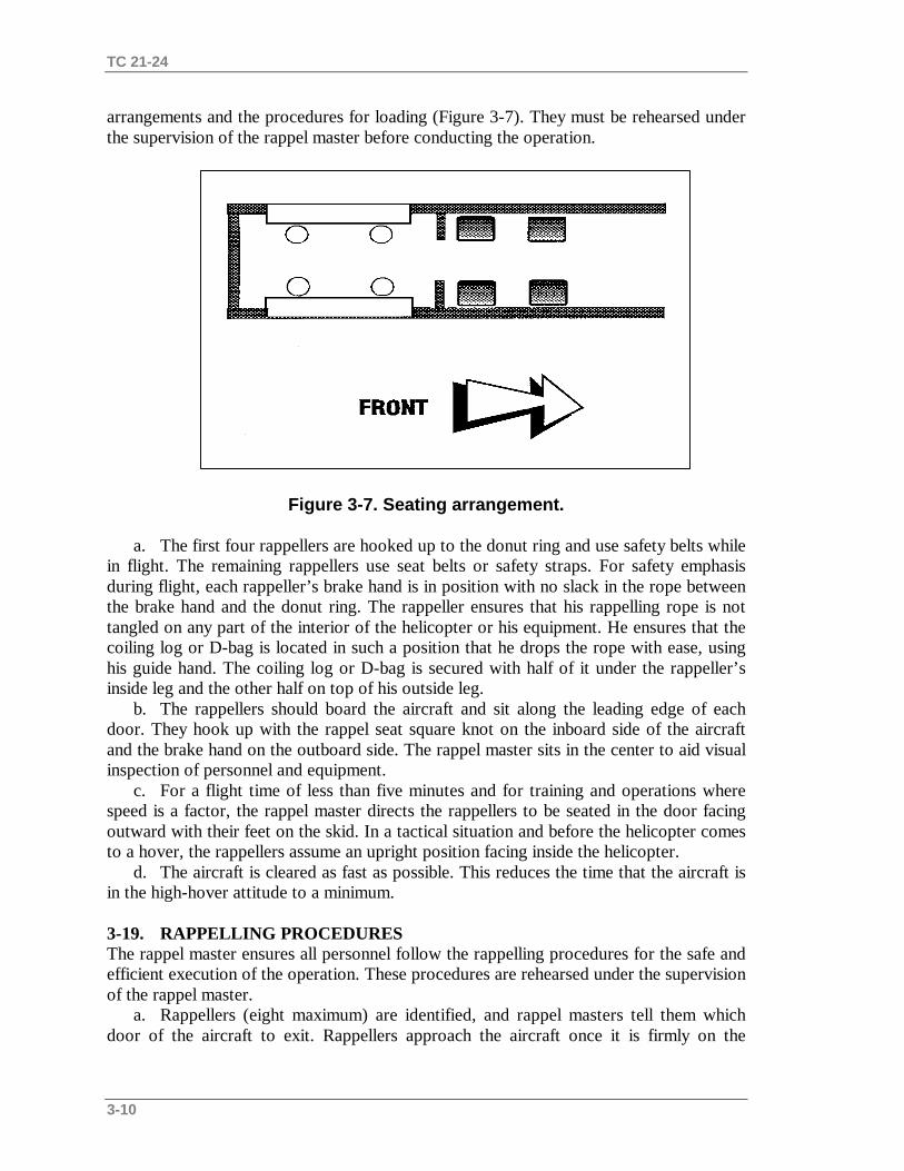
TC 21-24
3-10
arrangements and the procedures for loading (Figure 3-7). They must be rehearsed underthe supervision of the rappel master before conducting the operation.
Figure 3-7. Seating arrangement.
a. The first four rappellers are hooked up to the donut ring and use safety belts whilein flight. The remaining rappellers use seat belts or safety straps. For safety emphasisduring flight, each rappeller’s brake hand is in position with no slack in the rope betweenthe brake hand and the donut ring. The rappeller ensures that his rappelling rope is nottangled on any part of the interior of the helicopter or his equipment. He ensures that thecoiling log or D-bag is located in such a position that he drops the rope with ease, usinghis guide hand. The coiling log or D-bag is secured with half of it under the rappeller’sinside leg and the other half on top of his outside leg.
b. The rappellers should board the aircraft and sit along the leading edge of eachdoor. They hook up with the rappel seat square knot on the inboard side of the aircraftand the brake hand on the outboard side. The rappel master sits in the center to aid visualinspection of personnel and equipment.
c. For a flight time of less than five minutes and for training and operations wherespeed is a factor, the rappel master directs the rappellers to be seated in the door facingoutward with their feet on the skid. In a tactical situation and before the helicopter comesto a hover, the rappellers assume an upright position facing inside the helicopter.
d. The aircraft is cleared as fast as possible. This reduces the time that the aircraft isin the high-hover attitude to a minimum.
3-19. RAPPELLING PROCEDURESThe rappel master ensures all personnel follow the rappelling procedures for the safe andefficient execution of the operation. These procedures are rehearsed under the supervisionof the rappel master.
a. Rappellers (eight maximum) are identified, and rappel masters tell them whichdoor of the aircraft to exit. Rappellers approach the aircraft once it is firmly on the

TC 21-24
3-11
ground, and the crew chief signals when it is safe to approach. The approach to theaircraft should be about 45 degrees to the nose of the aircraft allowing the pilot to see therappeller.
b. If the rappel master is not already on the aircraft, he boards first and secureshimself to the aircraft with a safety harness. He dons a headset to maintaincommunications with the pilot and positions himself behind the crew chief’s chair.
c. As the rappellers approach the aircraft, they hand their anchor attaching points(snaplinks connected to their ropes) to the rappel master. The rappel master connects oneset of snaplinks to the floating safety ring and one set of snaplinks (the primary) to thedonut ring.
d. All rappellers use safety belts. For safety emphasis during flight, each rappeller’sbrake hand is in position with no slack in the rope between the brake hand and the donutring. Rappellers ensure that their rappelling ropes are not tangled on any part of theinterior of the helicopter or their equipment. They ensure that they can drop their D-bagor log coil using the guide hand. The D-bag or log coil is placed so it does not fall out ofthe aircraft. Once over the target area, the rappel master issues the rappel commands andensures the rappel ropes are on the ground (about 20 feet of rope should be on theground).
e. On the command GO, the rappeller flexes at the knees and vigorously pushesaway from the skid gear, allowing the rope to pass through his brake hand and guidehand. The descent is accomplished smoothly at a rate of about 8 feet per second, avoidingjerky stops. The rappeller initiates his braking action slowly when he is about halfway tothe ground. The safety officer or NCO ensures that at least a five-second delay ismaintained between each rappeller. Another technique used to deploy rappellers is toissue the command GO to the rappellers diagonally opposite each other. In the earlyphase of performance, the rappeller’s feet are together (particularly if over woods orjungle) and his guide hand is used (not the brake hand) to remove any entanglements.
f. Upon reaching the ground, the rappeller clears the rappel rope through thesnaplink (or rappel ring) until the rope is free. If other rappellers are to follow on thesame rope, the rappeller on the ground separates or untwists the ropes and becomes thebelayer for each subsequent rappeller. If ropes are to be released from the aircraftfollowing the last rappeller, untwisting and separating the ropes is not necessary. A two-second interval is maintained between exit groups (two men exiting at the same time).
g. The rappel master releases the rope from the donut ring after he confirms (byvisual inspection) that the rappeller is off rappel. He then drops the rope away from thehelicopter.
3-20. RAPPELLING COMMANDSHelicopter rappelling is conducted in a noise-filled environment. Each rappeller is trainedto know the rappel commands and to understand the actions required of him during theexecution of each command. Due to the noise created by the helicopter, all rappelcommands should be accompanied by arm-and-hand signals. All commands are issued bythe rappel master and confirmed orally by the rappellers.
a. The helicopter rappelling commands are as follows:(1) GET READY. The rappeller checks his combat equipment, looks toward the
donut ring, and pulls the rope to check the anchor point connection. He then checks his

TC 21-24
3-12
snaplink to ensure the rope is properly seated in the snaplink on his rappel seat.(2) THROW ROPE. The rappeller drops his deployment bag out and away from the
helicopter with his guide hand. He ensures that the rope does not fall between the side ofthe helicopter and the skid. The rappel master ensures the rope is touching the ground andis free of tangles and knots. The rappeller then replies, “Rope okay.”
(3) SIT IN THE DOOR. The rappeller swings his legs to the outside of the helicopterand takes up a sitting position. (This command applies only to the UH-1H helicopter.)
(4) POSITION. The rappeller pivots 180 degrees on the skid. His feet are shoulder-width apart, the balls of his feet are on the skid, his knees are locked, his body is bentforward in an L-shape position, and his brake hand is on his buttock. The rappel mastermakes a visual inspection of the snaplink and rappel ring.
(5) GO. The rappel master points at the rappeller to exit. One rappeller from each siderappels at the same time. The rappel master gives the command GO to the rappellers thatare diagonal to each other— for example, the front left rappeller and the rear rightrappeller. The rappeller flexes his knees and jumps backward, letting the rope runthrough the brake hand and guide hand.
b. The arm-and-hand signals that are used with rappelling commands are as follows:(1) GET READY (Figure 3-8). The rappel master extends both arms to the front with
fists clenched and thumbs pointing upward.
Figure 3-8. Arm-and-hand signal for GET READY.
(2) SIT IN THE DOOR (Figure 3-9). The rappel master extends both arms to thefront with elbows locked, fingers extended, thumbs running along the index fingers, andpalms facing downward. He bends slightly at the waist so that the arms are below thewaist. Then, he moves both arms in a crisscross waving motion, alternating left over rightand right over left.
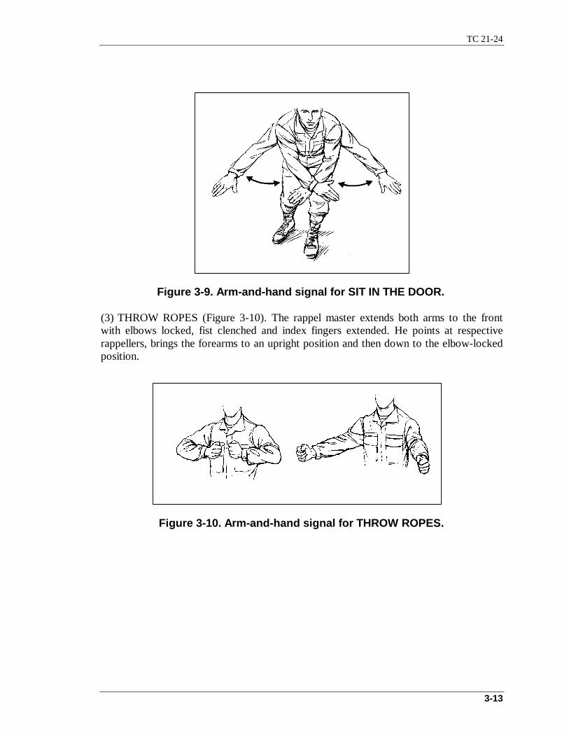
TC 21-24
3-13
Figure 3-9. Arm-and-hand signal for SIT IN THE DOOR.
(3) THROW ROPES (Figure 3-10). The rappel master extends both arms to the frontwith elbows locked, fist clenched and index fingers extended. He points at respectiverappellers, brings the forearms to an upright position and then down to the elbow-lockedposition.
Figure 3-10. Arm-and-hand signal for THROW ROPES.

TC 21-24
3-14
Figure 3-11. Primary arm-and-hand signal for POSITION.
(4) POSITION. The two arm-and-hand signals for POSITION are:(a) Primary signal (Figure 3-11). The rappel master extends both arms to the front,
elbows bent, forearms pointed upward, fists clinched, and index fingers pointing upward.He makes a circular motion with both forearms rotating in opposite directions.
(b) Alternate signal (Figure 3-12). The rappel master extends both arms to the frontwith elbows locked, fists clenched, and index fingers extended. He bends at the waist sothat his arms are below his waist and makes a circular motion with arms rotating inopposite directions.
Figure 3-12. Alternate arm-and-hand signal for POSITION.
(5) GO (Figure 3-13). The rappel master extends an arm with elbow locked, fingersextended, and thumb along the index finger, and he points directly at the rappeller.

TC 21-24
3-15
Figure 3-13. Arm-and-hand signal for GO.
3-21. INSPECTION AND SAFETY CONSIDERATIONSThe rappel master and pilot (or his representative) conduct a joint inspection of theaircraft to ensure the safety of all personnel and serviceability of equipment.
a. Cargo doors are locked in the open position or cleared for closing, depending onthe mission.
b. All loose objects in the cargo compartment are removed or secured forward.c. Sharp edges or protrusions on the cargo floor and door ledges are taped.d. The donut ring and floating safety ring are serviceable and properly attached to
tie-down fittings.e. A headset and intercom jack for the rappel master are available and operational.f. Serviceable safety harnesses are available for the rappel master and crew chief.g. The recovery rope is installed and properly stowed.h. Unused floor rings are taped down.
Section VI. RAPPELLING OPERATIONS FOR UH-60 BLACKHAWKHELICOPTER
The techniques used by the rappeller when rappelling from different aircraft are similar.However, positioning, seating, and the tie-down anchor point are different. Each rappelleris well trained on each aircraft before conducting a rappel.
3-22. CHARACTERISTICSThe UH-60 is a twin-engine, medium-speed, single-main rotor helicopter that cantransport 10 rappellers, 1 rappel master, and 1 four-man crew when the center row oftroop seats is removed. It is equipped with four 4,000-pound (load limit) cabin ceiling tie-down fittings or rings that are located in the ceiling of the troop/cargo compartment.These fittings are used as the primary rappelling rope anchoring points. The UH-60 is
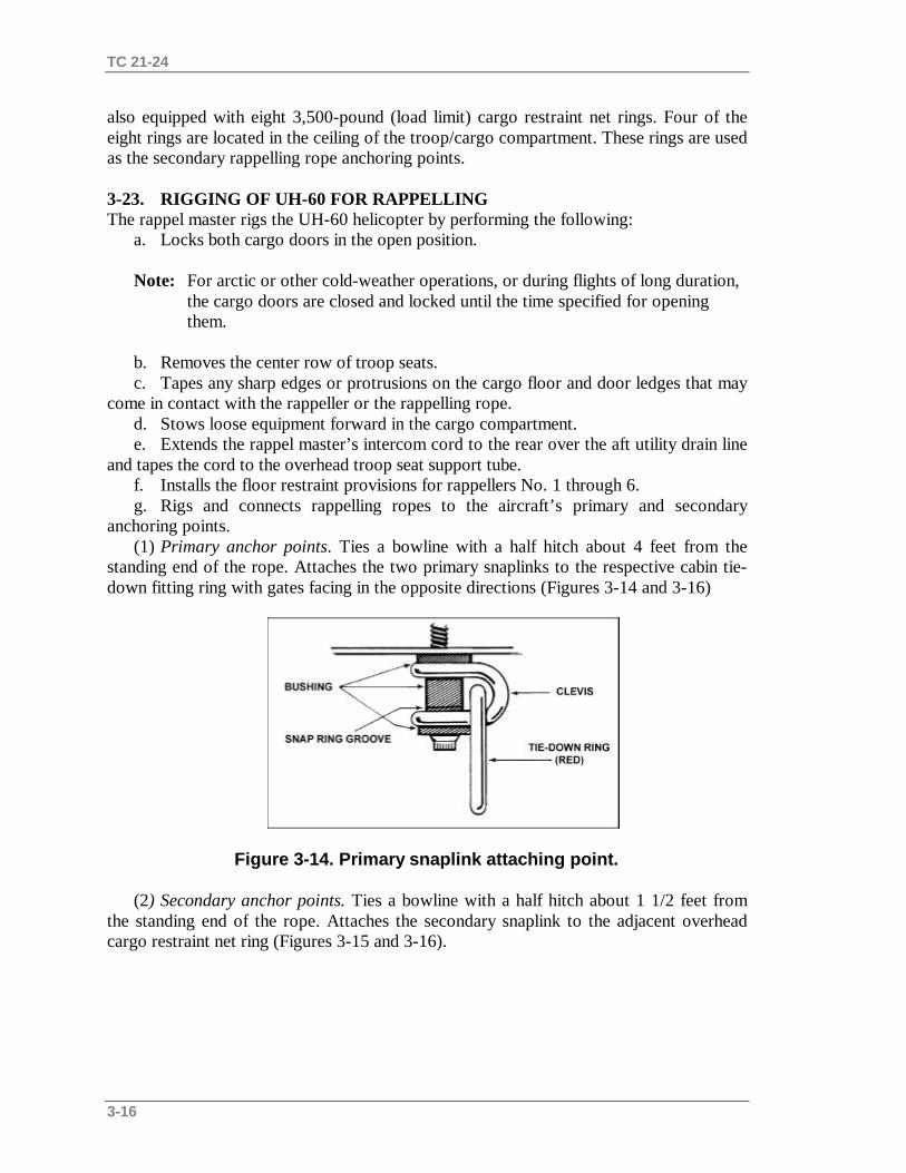
TC 21-24
3-16
also equipped with eight 3,500-pound (load limit) cargo restraint net rings. Four of theeight rings are located in the ceiling of the troop/cargo compartment. These rings are usedas the secondary rappelling rope anchoring points.
3-23. RIGGING OF UH-60 FOR RAPPELLINGThe rappel master rigs the UH-60 helicopter by performing the following:
a. Locks both cargo doors in the open position.
Note: For arctic or other cold-weather operations, or during flights of long duration, the cargo doors are closed and locked until the time specified for opening them.
b. Removes the center row of troop seats.c. Tapes any sharp edges or protrusions on the cargo floor and door ledges that may
come in contact with the rappeller or the rappelling rope.d. Stows loose equipment forward in the cargo compartment.e. Extends the rappel master’s intercom cord to the rear over the aft utility drain line
and tapes the cord to the overhead troop seat support tube.f. Installs the floor restraint provisions for rappellers No. 1 through 6.g. Rigs and connects rappelling ropes to the aircraft’s primary and secondary
anchoring points.(1) Primary anchor points. Ties a bowline with a half hitch about 4 feet from the
standing end of the rope. Attaches the two primary snaplinks to the respective cabin tie-down fitting ring with gates facing in the opposite directions (Figures 3-14 and 3-16)
Figure 3-14. Primary snaplink attaching point.
(2) Secondary anchor points. Ties a bowline with a half hitch about 1 1/2 feet fromthe standing end of the rope. Attaches the secondary snaplink to the adjacent overheadcargo restraint net ring (Figures 3-15 and 3-16).
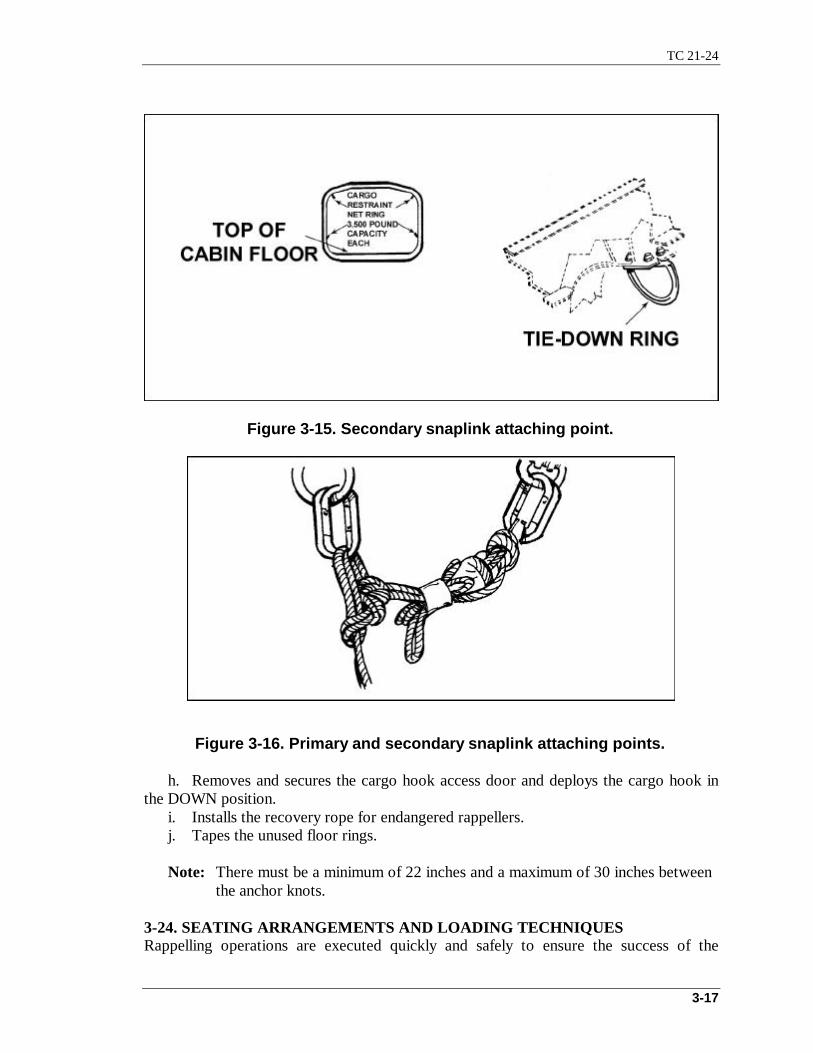
TC 21-24
3-17
Figure 3-15. Secondary snaplink attaching point.
Figure 3-16. Primary and secondary snaplink attaching points.
h. Removes and secures the cargo hook access door and deploys the cargo hook inthe DOWN position.
i. Installs the recovery rope for endangered rappellers.j. Tapes the unused floor rings.
Note: There must be a minimum of 22 inches and a maximum of 30 inches between the anchor knots.
3-24. SEATING ARRANGEMENTS AND LOADING TECHNIQUESRappelling operations are executed quickly and safely to ensure the success of the
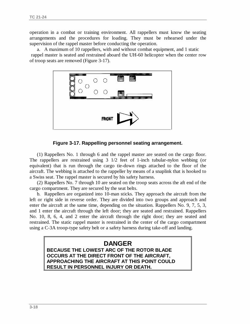
TC 21-24
3-18
operation in a combat or training environment. All rappellers must know the seatingarrangements and the procedures for loading. They must be rehearsed under thesupervision of the rappel master before conducting the operation.
a. A maximum of 10 rappellers, with and without combat equipment, and 1 static rappel master is seated and restrained aboard the UH-60 helicopter when the center rowof troop seats are removed (Figure 3-17).
Figure 3-17. Rappelling personnel seating arrangement.
(1) Rappellers No. 1 through 6 and the rappel master are seated on the cargo floor.The rappellers are restrained using 3 1/2 feet of 1-inch tubular-nylon webbing (orequivalent) that is run through the cargo tie-down rings attached to the floor of theaircraft. The webbing is attached to the rappeller by means of a snaplink that is hooked toa Swiss seat. The rappel master is secured by his safety harness.
(2) Rappellers No. 7 through 10 are seated on the troop seats across the aft end of thecargo compartment. They are secured by the seat belts.
b. Rappellers are organized into 10-man sticks. They approach the aircraft from theleft or right side in reverse order. They are divided into two groups and approach andenter the aircraft at the same time, depending on the situation. Rappellers No. 9, 7, 5, 3,and 1 enter the aircraft through the left door; they are seated and restrained. RappellersNo. 10, 8, 6, 4, and 2 enter the aircraft through the right door; they are seated andrestrained. The static rappel master is restrained in the center of the cargo compartmentusing a C-3A troop-type safety belt or a safety harness during take-off and landing.
DANGERBECAUSE THE LOWEST ARC OF THE ROTOR BLADEOCCURS AT THE DIRECT FRONT OF THE AIRCRAFT,APPROACHING THE AIRCRAFT AT THIS POINT COULDRESULT IN PERSONNEL INJURY OR DEATH.

TC 21-24
3-19
3-25. RAPPELLING PROCEDURESThe rappel master ensures all personnel follow the rappelling procedures for the safe andefficient execution of the operation. These procedures are rehearsed under the supervisionof the rappel master.
a. The rappel master is equipped with a headset and maintains communications withthe pilot at all times. He wears a safety harness and stations himself in the center of thecargo floor to maintain control of the rappellers, their ropes, and all anchor attachingpoints.
Note: If all rappellers are rappelling into the same area, individual rappel ropes arenot needed. The ropes used by rappellers No. 1 through 4 are used by thesucceeding rappellers.
b. After all rappellers are in the aircraft, rappellers No. 1 through 4 hand the rappelmaster their primary and secondary anchor point snaplinks. The rappel master hooks theprimary anchor point snaplink into the respective cabin tie-down fittings and thesecondary anchor point snaplink into the respective cargo restraint net rings. After theprimary and secondary anchor point snaplinks are secured, the first four rappellers hookonto their respective rappel rope. The rappel master checks the first four rappellers for thecorrect hookup.
c. After the first four rappellers exit and clear their ropes, the rappel master handsthe next four rappellers their rappel ropes to hook up. Left-handed rappellers take extraprecaution to ensure the correct hookup. Problems can be avoided by placing left-handedrappellers in the positions where they initially have the rope to their nonbrake side.
WARNINGExtreme care must be taken in hooking up and positioningpersonnel that require repositioning of their rope to theirproper brake-hand side. This could result in bodily injury ordamage to Army property.
d. After checking the rappellers for the correct hookup, the rappel master moves thenext four rappellers into position on the floor of the aircraft. After the four rappellers exitand clear their ropes, the rappel master hands the last two rappellers their rappel ropes tohook up.
e. After checking the rappellers for correct hookup, the rappel master moves theminto position on the floor of the aircraft. After the last rappeller is off the rope, the rappelmaster releases the ropes.
f. If the rappel master rappels, the crew chief is instructed to release or retrieve theropes.
3-26. RAPPELLING COMMANDSThe UH-60 rappelling is conducted similar to the UH-1H rappelling with the exception

TC 21-24
3-20
that no skids are on the UH-60 on which to stand. Therefore, the edge of the floor, alongthe door of the helicopter, is used as a pivot point to assume the L-shaped rappellingposition.
a. GET READY. This alerts the rappeller. The rappeller and rappel master performfinal checks of the hookup, rappel seat, snaplink, and equipment.
b. THROW ROPES. The rappeller looks down below the aircraft to ensure that noone is under the aircraft. Keeping his brake hand in the small of his back, he tosses thedeployment bag with the ropes out and away from the helicopter with his guide hand.The rappeller observes that the ropes are touching the ground and are not knotted orentangled.
c. POSITION. From a kneeling position with the brake hand in the small of theback, the rappeller rotates 90 degrees so that he is facing the inside of the aircraft and therappel master. The rappeller then places his heels on the edge of the floor of thehelicopter doorway and leans out into an L-shaped position. His feet are shoulder-widthapart, the balls of his feet are on the edge of the helicopter doorway, his knees are locked,and his body is bent at the waist toward the helicopter.
d. GO. The rappel master initiates the rappel with this command. The rappellerflexes his knees and jumps backwards. At the same time, the rappeller throws his brakehand out at a 45-degree angle, letting the running ends of the ropes slide through both thebrake hand and guide hand.
3-27. INSPECTION AND SAFETY CONSIDERATIONSThe rappel master and pilot (or his representative) conduct a joint inspection of theaircraft to ensure the safety of all personnel and serviceability of equipment.
a. Cargo doors are locked in the open position or cleared for closing, depending onthe mission.
b. All loose objects in the cargo compartment are removed or secured forward.c. Sharp edges or protrusions on the cargo floor and door ledges that may come in
contact with the rappeller or his rappelling rope are taped.
Note: Do not tape the door latches or handles; this can interfere with door operations.
d. Primary and secondary rappelling anchor points are serviceable and securelyattached to the aircraft structure.
e. A headset/helmet and intercom jack for the rappel master are available andoperational, and the intercom extension cord is secured overhead.
f. Serviceable safety harnesses are available for the rappel master and crew chief.g. The cabin ceiling tie-downs must have safety wire installed to ensure they do not
come undone or unraveled, and the bolt head must be stamped H.
Section VII. RAPPELLING OPERATIONS FOR MH-53 HELICOPTERThe MH-53 helicopter is a highly versatile aircraft. It is used for a variety of missions,usually in conjunction with special operations.
3-28. CHARACTERISTICSThe MH-53 is a two-engine, single-rotor, heavy-lift helicopter. It has a crew of six and

TC 21-24
3-21
can be refueled while in flight. It has a precision navigational and communicationspackage, which makes it excellent for conducting deep infiltration and exfiltrationmissions. The MH-53 helicopter can fly at night in all weather and terrain conditions. Itcan follow down to 100 feet and operate from unprepared sites. It is fitted with three gunstations for a mix of 7.62-mm miniguns and caliber .50 machine guns.
3-29. RIGGING OF MH-53 HELICOPTER FOR RAPPELLINGWhen rappelling from the crew entrance door, rappellers connect the ropes with lockingsnaplinks to the two 10,000-pound tie-down rings under the left scanner’s window. Whenrappelling from the ramp, rappellers connect the ropes with locking snaplinks to the two10,000-pound tie-down fittings on the left and right sides of the aircraft at station 522.Any sharp edges that could damage the ropes should be padded or taped. A length of firehose may also be used over the portion of the rope that comes in contacts with the door orramp edge.
3-30. SEATING ARRANGEMENTS AND LOADING TECHNIQUESThe MH-53 is a large, versatile helicopter. The seating arrangements and loadingtechniques are numerous. The using unit develops a seating and loading SOP that ensuresthe safety of all personnel and permits smooth, efficient execution of the mission.
3-31. RAPPELLING PROCEDURESThe rappel master or his assistant are at the two exit points (ramp and door). The rappelmaster maintains communications with the helicopter commander and relays allcommands and time warnings. The commander issues time warnings at 20-minute, 10-minute, 5-minute, and 1-minute intervals. During limited visibility, the rappel master mayuse NVDs to observe the safety/belayer. Chemical lights are attached to the top or bottomof the rappel rope. Arm-and-hand signals should be IAW The Air Assault SchoolHandbook and FC 57-2.
Note: Night vision goggles cause limited depth perception and a tunnel vision effect.
a. The rappel master is secured by a harness and ensures the proper hook up of eachrappeller. Once hooked up, the rappellers release their safety belts. At the command ofthe rappel master, the rappellers position themselves to ease immediate deployment.
WARNINGBefore conducting deployments off the ramp, the deployingteam members must be briefed on the importance ofmaintaining separation between members. About 24 to 27inches are desired. This separation helps maintain aircraftcenter of gravity limits.
b. The rappel master deploys ropes only after the helicopter is in a stable hover overthe target area and he has given the command ROPES. He ensures the ropes are on theground before giving the command GO. After the last rappeller is off the rope, the rappel
TC 21-24
3-22
master retrieves or cuts the ropes away.
3-32. RAPPELLING COMMANDSThe helicopter rappelling commands for the MH-53 are as follows:
a. GET READY. This command is given as the helicopter approaches the rappelsite. It alerts the rappellers of the approach to the site and signals them for a finalequipment check.
b. POSITION. This command clears the first rappellers into position fordeployment.
c. THROW ROPE. This command is given once the helicopter reaches a stablehover.
d. GO. The rappellers exit.
3-33. INSPECTION AND SAFETY CONSIDERATIONSThe rappel master briefs all personnel participating in the operation. He conducts hands-on inspection to ensure the safety of all personnel and serviceability of equipment.
a. Tie-down fittings are serviceable.b. All sharp or protruding edges that may come in contact with the rappelling ropes
are padded or taped.c. All ropes are retrieved or cut away before forward movement of the helicopter.d. Only three rappellers are deployed at a time— two from the ramp and one from
the personnel door.

4-1
CHAPTER 4
SPECIAL PATROLINFILTRATION/EXFILTRATION SYSTEM
The special patrol infiltration/exfiltration system (SPIES) providesan excellent form of exfiltration over short distances. It is notrecommended for infiltration because team members are exposed theentire time. Due to the nature of SPIES operations, a thorough briefingis required for all participants before the operation. Personnel beingextracted must train extensively in the SPIES extraction beforeinfiltration. For the other personnel involved, a complete preoperationsbriefing is held before the operation. This is crucial when additionalassets are involved other than the extraction helicopter such asgunships, aerial observers, or artillery support.
Section I. SPIES MASTER DUTIES AND QUALIFICATIONSThe SPIES master holds the rank of sergeant or above (may be waived by thecommanding officer). The commanding officer ensures that this qualification is enteredon the soldier’s training record.
4-1. QUALIFICATIONSTo qualify to be a SPIES master, the sergeant must participate in at least three SPIESoperations (observe twice and execute SPIES master duties once under observation).For example, he hooks up the helicopter, assists in the preparation of an operation, andconducts a successful operation under the supervision of a qualified SPIES master. ASPIES master is conscientious and thorough, and he knows all aspects of a SPIESoperation. He can give an effective pilot’s brief, use the aircraft communicationsequipment, and understand aviation terminology.
4-2. DUTIESThe SPIES master is responsible for the safe conduct of the SPIES operation.
a. Preflight Duties.(1) Inventories and inspects all SPIES equipment.(2) Briefs the pilot and other concerned personnel about details of the operation,
especially the extraction and dismounting procedures.(3) Ensures that an ICS helmet and gunner’s belt are available for the SPIES
master’s use. Uses a sling rope if no belt is available. Connects and checks theoperation of the ICS to be used. (ICS communications is established between the SPIESmaster and pilots on all SPIES operations.)
(4) Attaches the SPIES rope to the helicopter IAW the guidance in this chapter.(5) Ensures that nothing is adrift in the aircraft that may fall on a team member.(6) Checks the location of the emergency axe. Places the axe where readily
available, yet secure enough so as not to endanger the men on the SPIES rope. (Inspectsthe axe to ensure that it is sharp.)
b. Extraction Duties.(1) On arrival at the team’s estimated position, assists the pilot in determining the
exact location of the team members.

TC 21-24
4-2
(2) As the aircraft approaches the team’s location, aids the pilot (using the clocksystem) in placing the aircraft directly above the team.
(3) Requests permission from the pilot to drop the SPIES rope when the aircraft ishovering above the team.
(4) Drops the rope, taking care to avoid striking team members on the ground.(5) Notifies the pilot when the rope is down, and reports all altitude corrections to
ensure that team members reach all SPIES attachment points.(6) Watches for the “thumbs-up” signal from all team members.(7) On receipt of the “thumbs-up” signal, advises the pilot that the team is ready for
extraction and requests a vertical lift-off.(8) Advises the pilot of the team’s position, the location of any potential obstacles,
and the avoidance of horizontal movement.(9) If a team member becomes entangled with an obstacle during the extraction,
notifies the pilot and requests that the vertical lift be stopped. If the situation is critical,prepares to cut the SPIES rope (the anchor point or cargo straps) after the team membersare secured to the obstacle or on the ground.
(10) When positive that all obstructions are clear, advises the pilot to obtain a safealtitude (about 350 feet AGL for training purposes or as the situation dictates in combat)or to transition into forward flight.
(11) At frequent intervals during the flight, advises the pilot on the safety status ofall team members. Maintains a constant visual watch on the team and checks security ofthe SPIES attachments often.
c. Dismounting Duties.(1) On arrival at the dismounting area, informs the pilot as to the approximate
distance of the lower rope end from the ground.(2) Once the pilot starts the vertical descent, continually informs him as to the
approximate distance of the lower rope end from the ground.(3) Informs the pilot of any horizontal drift that occurs and any obstructions near the
SPIES rope. Also informs the pilot of any oscillation that may occur.(4) Informs the pilot when the rope is about 25 feet above the ground and again when
it is 10 feet above the ground. Ensures that the rate of descent is slow enough to enablethe team members to land and get out from under team members safely.
(5) Reports when the first man initially touches down, when the last team memberstarts to safely move away from under the helicopter, and when all team members aredisconnected.
(6) On order of the pilot, either retrieves the SPIES rope into the helicopter ordisconnects the SPIES rope and drops it to the ground. When using the UH-1H/UH-60helicopter, the only way to retrieve the SPIES rope while in the air is by having anarranged recovery rope attached with a 16-foot sling rope. In some cases, the SPIESmaster joins two 12-foot-long sling ropes to haul the SPIES rope aboard and attaches therope about 5 or 6 feet below the cargo hook or cargo strap hookup point. The type of knotused to connect the sling (or recovery) rope to the SPIES rope is self-tightening in nature(for example, the prusik knot). The SPIES master fastens the standing end of the slingrope to the deck tie-down or uses a snaplink. Although it is important to keep the line outof the way, the primary consideration is its length. The rope must be long enough for anyoscillation in the SPIES during flight.

TC 21-24
4-3
Section II. PREOPERATIONS BRIEFINGS AND PROCEDURESBefore conducting a SPIES training mission, the participants must have a basicunderstanding of the requirements. The SPIES master conducts briefings to ensure thesoldier extracted and the pilot know the procedures. As SOPs are developed and unitstrain together, the SPIES master simply refers to the SOP. He always gives a safetybriefing and conducts an equipment inspection.
Note: SPIES has not been approved for Army-wide use. Approval must be obtainedfrom division level or higher commander before the conduct of any training.
4-3. SAFETYAs in all training, a safety briefing must precede operations using the SPIES. The briefingshould consist of, but not be restricted to, a review of the following:
• Characteristics of equipment associated with the SPIES.• Equipment inspection.• Proper donning of the harness.• Methods of extraction and insertion used.• Emergency signals.
4-4. COMMUNICATIONSDue to the noise level associated in all helicopter operations, radios are used forcommunication. They are also used before the arrival of the helicopter. Precise arm-and-hand signals are established in case of radio failure or poor communications due to staticor noise overriding the audio output of the radio. During the first part of the operations,the SPIES master either observes (daytime) or knows that a definite procedure is takingplace (night or jungle) while the teams are hooking up to the SPIES rope for extraction.Headsets and voice suppressors replace the handset for better radio procedures. Thisallows the RATELO on the ground to use both hands while the helicopter hovers for afaster and safer hookup. If radio communications are hampered, special procedures areused along with hand or light signals.
4-5. EXTRACTION PROCEDURESAfter the team has been located, the SPIES master assists the pilot in directing thehelicopter to the proper distance over the team.
a. The team leader positions himself so that he can move and approach the rope as itis dropped by the SPIES master. Once the rope is clear of any obstacles, the team leadersignals the team to their assigned positions along the 10 hookup points. Using theprimary or harness snaplink, each team member hooks to the D-ring on his side of theline. This is the primary hookup. Once the team is hooked up, the team leader hooks intothe alternate or second hookup point using the safety line and snaplink. He then facesforward along the line so that he is heading in the direction he is traveling when theaircraft starts its ascent.
b. The SPIES rope is held up and routed over the shoulder closest to the rope. Withthe other hand, the team members give thumbs-up signals to allow both the team leaderand the SPIES master to see that they are ready to go. The team leader physically inspects

TC 21-24
4-4
(if time and situation permits) or hooks himself in on the lowest point along with theRATELO to ensure the running end is clear of all obstacles. He gives the thumbs-upsignal to the SPIES master. This thumbs-up signal (at night, an arranged light signal)continues until the team is lifted off the extraction surface. The team leader also signals(arms held straight to the sides) when the team is at safe altitude (approximate 10 feetabove the tallest obstacle at the extraction site). The helicopter starts a transition in ahorizontal direction on its return flight.
4-6. EMERGENCY PROCEDURESDuring the flight, from extraction until the team is safely and quickly detached from theSPIES rope, each team member should be aware of any problems that arise from above orbelow. The man above checks the man below. At the first sign of danger or if anemergency arises, the team leader or a team member places his free hand on his head.Upon observing anyone on the SPIES rope with his hand on his head, the SPIES mastertells the pilot to make an emergency landing in the nearest and safest area.
4-7. DISMOUNTING PROCEDURESDuring the familiarization training phase, the SPIES master ensures all members knowthey should immediately head in the direction of the nose (12 o’clock) of the aircraft.This allows the pilot to see that the team is out from under the aircraft. When anemergency situation arises, the pilot can make a better appraisal of the situation if he cansee all the members of the team. When the helicopter is making a scheduled landing, theteam ensures that the SPIES rope does not interfere with the aircraft and that the aircraftdoes not land on the rope.
4-8. INSPECTION OF EQUIPMENTThe SPIES is inspected by a certified SPIES master at six-month intervals and wheneverthe SPIES master questions serviceability. Outdated, spliced, abraded, or cut rope isremoved from service. However, loose or broken stitching in excess of three stitches isnot repaired.
CAUTIONAcid contamination, cuts, or fraying of harness or slingwebbing constitute nonrepairable damage.
a. The certified SPIES master inspects the harness and suspension sling webbing forsigns of contamination from oil, grease, acid, or rust. He also checks for cuts, twists,fading, excessive wear, fusing (indicated by unusual hardening or softening of webbingfibers), fraying, burns, abrasions, and loose or broken stitching. The damaged harness orsuspension sling is removed from service and returned to supply for appropriatedisposition.
b. The SPIES master inspects all hardware for signs of corrosion, pitting, ease ofoperation, security of attachment, bends, dents, nicks, burrs, and sharp edges.

TC 21-24
4-5
Replacement of hardware (except chest strap adapter) that requires unstitching ofwebbing renders the harness unserviceable.
c. The SPIES master replaces the V-ring by cutting the strap above the stitching. Hefolds and stitches a new end section of the leg strap. If the leg strap is damaged, theSPIES master returns the harness or suspension sling to supply for appropriatedisposition.
d. The SPIES master checks ropes, harnesses, and suspension slings for expirationof service or total life, which is 7 years of service (opening manufacturer’s package) or15 years from date of manufacture, whichever occurs first. The SPIES master alsoensures the rope is free of splices. He ensures the eye loop at the end of the SPIES rope isnot broken, frayed, or loose.
e. The SPIES master inspects the rope surface for cuts, excessive abrasions, andsnags. Cuts on the rope are excessive when there are four or more cut strands in any 5-inch length. The two-to-one braided rope has 12 pairs of strands (24 individual strands)around the circumference. Abrasion is extensive when torn yarns are equivalent to that offour strands of any 5-inch length. Rope that has been subjected to heavy loads maydisplay glazed areas where it has worked against hard surfaces. This condition may becaused by paint or fused fibers. After long use, the rope may become fuzzy on the surface(although this should be minimized with the surface coating). However, the effect on therope’s strength is negligible.
f. The SPIES master inspects the rope for signs of contamination by acid, alkalinecompounds, salt water, fire extinguishing solutions, and petroleum-based solvents.Although the ropes gradually change color, such changes do not indicate decrease instrength unless the change is due to contact with strong chemicals. Changes in colorcaused by chemicals are usually spotty; changes caused by use are uniform throughoutthe length of the rope.
4-9. RIGGING OF UH-1H HELICOPTER FOR SPIES OPERATIONPersonnel who are not familiar with SPIES are encouraged to observe or take part in therigging of the helicopter. This builds confidence in the equipment and assists in a morecomprehensive training of new SPIES masters.
a. Equipment.
• One 120-foot SPIES rope with deployment bag.• Two 11-foot, 3- or 4-loop cargo slings or two 9-foot, 3- or 4-loop cargo slings.• Two Type IV connector links (four if aircraft does not have cargo hooks).• Heavy duty tape (100-mph tape).• One 12-foot sling rope.• Five oval snaplinks (nine if the aircraft does not have cargo hooks).
NOTE: If the aircraft does not have cargo hooks, use four 11-foot or four 9-foot, 3- or4-loop cargo slings.
b. Installation.(1) The primary attachment point for the SPIES rope is the cargo hook. The end of
the SPIES rope having a polyurethane encapsulated eye is attached to the cargo hook.

TC 21-24
4-6
The two 9- or 11-foot long cargo suspension slings are joined to form one continuoussling, using a Type IV link. The sling is stretched out on the helicopter deck. One end istaken under the helicopter and through the eye of the SPIES rope. It is then connected onthe other end of the sling using a Type IV link assembly. The sling must pass between thehelicopter skids and the fuselage.
(2) Once the the SPIES rope and cargo straps are in place, the straps running acrossthe deck of the helicopter are secured in place by at least four and as many as eightsnaplinks. The snaplinks are evenly spaced across the deck and alternated from one sideof the strap to the other and top and bottom, so that the first snaplink is to the rear of thestrap and going around the bottom two straps. The next snaplink is in the front of thecargo strap and around the top two sections of the strap. This process continues until atleast four points are established.
(3) If eight snaplinks are available, then each tie-down has two reversed. If no hook isavailable or is not working properly, the SPIES can be used safely by doubling the cargoslings and Type IV links. Thus, two cargo straps are side by side for a total of four slingsand four Type IV links. Padding is used around the edge of the fuselage to protect thesling from damage.
(4) Care must be taken when using the UH-1H helicopter because of the ways inwhich it can be outfitted. Some helicopters have a step attached at the doorway. This is anadded obstruction not only during installation but also during the operation. Others mayhave rocket pods or machine guns mounted. Not all of the UH-1 helicopters are hookedup the same way each time.
4-10. RIGGING OF UH-60 HELICOPTER FOR SPIES OPERATIONThe SPIES master inspects all materials required to rig the helicopter.
a. Equipment.
• One 120-foot SPIES rope with deployment bag.• Two 11-foot, 3- or 4-loop cargo slings or two 9-foot, 3- or 4-loop cargo slings.• Two Type IV connector links (four if aircraft does not have cargo hooks).• Heavy duty tape (100-mph tape).• One 12-foot sling rope.• Five oval snaplinks (nine if the aircraft does not have cargo hooks).
Note: If the aircraft does not have cargo hooks, use four 11-foot or four 9-foot, 3- or4-loop cargo slings.
b. Installation.(1) The primary attachment point for the SPIES rope is the cargo hook. The end of
the SPIES rope has a polyurethane encapsulated eye that is attached to the cargo hook.The two 9- or 11-foot cargo suspension slings are joined to form one continuous slingusing a Type IV link. The sling is stretched out on the helicopter deck. One end is takenunder the helicopter and through the eye of the SPIES rope. It is then connected on theother end of the sling using a Type IV link assembly. The sling passes between thehelicopter skids and the fuselage. Padding is used around the edge of the cargo hatch toprotect the sling from damage.

TC 21-24
4-7
(2) Once the SPIES rope and cargo straps are in place, the straps running across thedeck of the helicopter are secured in place by at least four and as many as eight snaplinks.The snaplinks are spaced evenly across the deck and alternated from one side of the strapto the other and top and bottom. Thus, the first snaplink can be to the rear of the strap,wrapping around the bottom two straps. The next snaplink is in the front of the cargostrap and around the top two sections of the strap. This process continues until at leastfour points are established.
(3) If eight snaplinks are available, each tie-down has two snaplinks connecting thesame spot, and the swing gates are reversed. If no hook is available or is not workingproperly, the SPIES can be used safely by doubling the cargo slings and Type IV links.Two cargo straps are side by side with a total of four slings and four Type IV links.
4-11. RIGGING OF CH-46/CH-47 HELICOPTER FOR SPIES OPERATIONThe SPIES master inspects all the materials required to rig the helicopter.
a. Equipment.
• Two 11-foot, 3-loop slings.• Two 9-foot, 3-loop cargo slings.• Four Type IV connectors.• One 13-foot sling rope.
b. Installation.(1) The SPIES rope is attached using two 9- or 11-foot cargo suspension slings and
four Type IV links. The cargo slings are passed through the encapsulated eye of theSPIES rope and attached to the outboard cargo tie-down rings on the aircraft floor. Twotie-down rings are used for each sling. Padding is used around the edge of the cargo hatchto protect slings from damage.
(2) Not all of the tie-down rings will be in the exact same position on the helicopters.This is one of the main considerations in deviating from the installation procedures.When possible, the cargo straps are placed to form two U shapes. One strap is placedforward of the cargo hole in the center of the aircraft floor and one aft or toward the rearof the helicopter. Installed properly, the cargo straps hold the SPIES rope comfortably inthe center of and slightly below the opening of the cargo hatch.
(3) The use of snaplinks attached close to all four faulty tie-down points not onlyensures a backup in case of a faulty tie-down ring but also reduces the amount ofmovement in the cargo suspension straps. A total of eight snaplinks are used for addedsecurity at each point with the swing gates reversed.
Section III. LAND AND WATER EXTRACTIONIf the situation, mission, or terrain suggests the possibility of a SPIES extraction, theleader includes the SPIES harness in each individual’s equipment list. If the mission orinsertion precludes the wearing of the harness, it will be carried on the top and just insidethe flap of the pack being used. Once the extraction helicopter has been requested, theharness is retrieved and donned.

TC 21-24
4-8
4-12. LAND EXTRACTION PROCEDURESThe SPIES is used only when the team requires immediate extraction or is unable tomove to a clear (open) position suitable for helicopter landing.
a. The extraction helicopter proceeds to the area and establishes radio or visualcontact with the team. The backup helicopter equipped with the SPIES remains aloft andaway from the area. The helicopter maintains visual contact with the LZ and monitorsradio communications.
b. After the team has indicated readiness for pickup and the tactical situation hasstabilized, the extraction helicopter moves to the LZ by the safest route. When thehelicopter is above the team’s location, the SPIES master drops the SPIES rope on orderof the pilot after the aircraft has obtained a stable hover at slightly above treetop height.
c. The team hooks up the same as in the familiarization procedures. Team memberssling individual weapons over the shoulders, securing weapons and equipment towithstand the wind. A safety line is attached to prevent lost weapons during SPIESoperations. When the team is ready, the team leader gives a thumbs-up signal.
d. During extraction, the team RATELO maintains communications with theextraction helicopter. He gives a verbal backup to the thumbs-up signal and relays allinformation during the flight. His location is near or at the bottom hookup point so he canassist in giving accurate information about the extraction, clearing of obstacles, anddescent.
e. Lift-off of the extraction helicopter is vertical until the SPIES rope has cleared allobstacles. With the barrel directed downward at a 45-degree angle and outward, the teammembers fire their individual weapons using the hip position.
f. Once the SPIES rope is clear of all obstacles, the extraction helicopter changes tohorizontal flight and departs the area by the safest route. Airspeed is limited to 70 knotsin moderate climates and 50 knots in cold climates while team members are attached tothe SPIES rope.
g. When the extraction helicopter has reached a safe dismount area, a transaction ismade into hover flight at an altitude of 250 feet AGL. A vertical descent is started withthe SPIES master continuously providing information to the pilot on the distance fromthe ground to the lower end of the SPIES rope. The vertical descent rate of the aircraft (attouchdown) is less than 5 feet per second.
h. When the team reaches the ground, they immediately move out toward the frontof the helicopter. All team members rapidly unhook themselves and teammates that needassistance. Once this is completed, they either move away from the area and set upsecurity or assist in clearing the rope if the helicopter is going to land.
4-13. WATER EXTRACTION PROCEDURESThe SPIES is suitable for extracting teams from the water. For this procedure, threeinflatable life vests or any type of floatation device is tied to the SPIES rope to providebuoyancy for the rope while in the water. One floatation device is tied at each end of theattachment points, and one floatation device is tied in the middle of the attachment pointarea just above the middle two sets of D-rings. The team members to be extracted weartheir SPIES harnesses under their individual life vest. They can also wear swimming fins,masks, and snorkels (amphibious operations) to ease hooking up to the SPIES rope withinthe spray area beneath the hovering helicopter.

TC 21-24
4-9
a. After the extraction helicopter has attained a stable hover above the teammember’s location, the SPIES master drops the SPIES rope (with floatation attached) onorder from the pilot. When the team members complete the hookup to the SPIES rope,the team leader signals the SPIES master to start lift-off. Lift-off of the extractionhelicopter is vertical until all team members and the bottom end of the rope have clearedthe water. During the initial lift-off, team members know that they are to be draggedthrough the water. The team members prepare to roll on their backs until clear of thewater.
b. Flight speed and altitude are the same as over land. The dismounting proceduresremain the same, except when landing on a ship. Once on board, the team members taketheir orders from personnel in charge of the deck.
Section IV. AFTER-OPERATIONS PROCEDURESAfter-operations procedures include repairing, cleaning, and proper storage of therappelling equipment.
4-14. REPAIRING AND CLEANING OF EQUIPMENTThe contaminated ropes are washed with a mild detergent, such as liquid dish soap, andcold water followed by a rinse in clean, fresh water. Ropes are dried at a temperature notto exceed 140 degrees Fahrenheit. Stubborn oil, grease, hydraulic fluid, and otherpetroleum stains can be removed with the cleaning agent xylene (Grade A or B, TT-X916).
4-15. STORAGE OF EQUIPMENTTo avoid ultraviolet deterioration, the nylon materials should be protected from directsunlight. The SPIES rope is stowed in an aviator’s kit bag for protection when not in use.Bins or similar facilities are used for storage of SPIES equipment. Shelves used forstorage should be at least 4 inches from the walls and 12 inches from the floor. Areasused for storage should be well ventilated and free of oil, acid, cleaning compounds, andother contaminants. Equipment must not be stowed above or near hot water pipes orheating apparatus.

5-1
CHAPTER 5
FAST-ROPE INSERTION ANDEXTRACTION SYSTEM
The fast-rope insertion and extraction system (FRIES) isemployed by small units to make rapid infiltration and exfiltrationusing rotary-wing aircraft in confined areas. The use of FRIES isnormally restricted to situations where aircraft cannot land, andwhen mission requirements preclude the need for large amounts ofequipment, and ammunition or heavy crew-served weapons.
Note: Headquarters, Department of the Army (HQDA) policy specifies that FRIES isnot approved for Army-wide use and names the Commanding General, United StatesArmy Special Operations Command (CG USASOC) as the executive agent for FRIESdoctrine. The use of FRIES is restricted to special operations forces, pathfinders, long-range surveillance units, and HQDA-approved schools with a USASOC-approvedFRIES program of instruction. Requests for other units to conduct FRIES operationsshould be submitted to Commander, USASOC, ATTN: AOOP-TRS, Fort Bragg, NC28307-5000.
Section I. GENERALFRIES information is subject to change. Units that recognize the need to update thischapter should submit recommendations to Commander, USASOC, ATTN: AOOP-TRS, Fort Bragg, NC 28307-5000.
5-1. OBJECTIVESThe objectives of this chapter are to—
• Prescribe the requirements for FRIES qualification and training, includingproficiency sustainment, safety, and administrative procedures.
• Establish the scope of the duties and responsibilities of key personnel whoconduct FRIES operations.
5-2. GUIDANCE FOR COMMANDERSUnits that have HQDA approval to perform FRIES operations are authorized toconduct initial FRIES qualification and FRIES master (FRM) qualification training.Training requirements are established in this publication, USASOC Regulation 350-6,and applicable SOAR policies. Aircraft material requirements are specified by the USArmy Technology Applications Program Office (TAPO) .
a. FRIES training and operations are inherently risky; therefore, safety isparamount. All training and operations require in-depth attention to detail from planningthrough preparation and execution.
b. The following basic guidance applies to FRIES training and operations:(1) Unit commanders must personally approve FRIES training sites.

TC 21-24
5-2
(2) A risk analysis and or assessment must be completed before FRIES operations.(3) Night FRIES operations are medium risk or higher.(4) Units authorized to conduct FRIES operations may incorporate FRIES activities
in field training exercises only after personnel have become FRIES qualified.(5) Field exercises using FRIES activities are subject to the limitations imposed by
applicable directives, including mandatory support requirements.(6) Requests for waiver of procedures or restrictions prescribed herein must be
submitted in writing with endorsement of the first general officer in the requestingunit=s chain of command to HQ USASOC.
5-3. TRAINING PREREQUISITES
CAUTIONTrainers must ensure all personnel preparing to participate inFRIES training are tested with equipment to ensure they havesufficient upper body strength to safely perform the full scopeof roping duties.
Before allowing soldiers to participate in FRIES training and operations, the unitcommander must make sure the soldiers are physically fit. Minimum screening standardsthat apply to each training participant include—
• Having passed the Army physical fitness test within the past six months.• Having passed a medical examination within the past two years.• Being free of any injury or physical condition that could cause a potential safety
hazard during FRIES training.• Demonstration of ability to perform a controlled descent from a height of 15 feet
while carrying a 40-pound load (not including the basic duty uniform andcombat boots).
• Demonstration of ability to hold a static position on a FRIES rope for 20seconds, using hands and feet to lock in while carrying a 40-pound load.
• Being qualified and current to fly FRIES activities IAW HQ USASOC and theSpecial Operations Aviation Regiment (SOAR) Aircrew Training Program andapplicable policies (for aircrews).
Note: The peacetime maximum soldier load will not exceed 50 pounds. This includeshelmet, weapon, vest, web gear, and rucksack. Rucksack weight will not exceed35 pounds.
5-4. PERSONAL EQUIPMENT REQUIREDThe minimum personal equipment required for FRIES training or operations includes—
• Heavy leather gloves.

TC 21-24
5-3
• A helmet with a chin strap.• Protective goggles.• A long-sleeve shirt or jacket, long pants, and boots.• Hearing protection and identification tags for helicopter operations.
Section II. FRIES QUALIFICATION TRAININGEach major unit (commanded by an O5 or higher) is responsible for conducting its ownFRIES qualification and sustainment program. FRIES trainers will be FRIES master(FRM) qualified and current. Unit training should be tailored to unit and situation needs,however proponent requisites will not be reduced without written approval of the CGUSASOC.
5-5. INITIAL FRIES QUALIFICATION TRAININGBefore participating in fast-rope operations, personnel are briefed on the FRIES and itspurpose, capabilities, and limitations. The briefing also covers the duties andresponsibilities of the pilot in command (PIC), safety, FRIES master (FRM), theassistant FRIES master (AFRM), and any ground assistants. Once the FRIES briefingis conducted, the remainder of the initial training is hands-on practice of the properFRIES operational techniques.
a. Individuals are shown the proper techniques for boarding the aircraft, movingto the door, grasping and descending, locking-in, and clearing the rope. Individuals arealso shown the proper wear, hook-up, and use of the STABO extraction harness.
b. After the demonstration, all ropers participate in a practice exercise in whichthey properly perform the following tasks using a tower and subsequently an aircraft.All ropers must demonstrate a minimum of six properly executed FRIES descents (threewithout equipment and three with equipment) and at least one successful lock-in.
(1) Perform FRIES descent and lock-in from a tower at the 34-foot level. Trainingshould be progressive, starting from a tower at the 34-foot level without equipment andthen with equipment. All ropers must complete a successful lock-in at this level. Roperswill not progress above the 34-foot level until after demonstrating the ability to stopdescent, lock-in, and hold a stationary position for 20 seconds with equipment.
(2) Perform FRIES descent and lock-in from a tower at the 60-foot level. Therecommended succession will be no less than three successful FRIES descents on the60-foot tower, again starting without equipment, completing a lock-in, and finishingwith equipment.
(3) Perform FRIES descent from a helicopter at 60 feet or higher. Therecommended completion should be at least two helicopter descents from 60 feet orhigher (one without equipment and one with equipment).

TC 21-24
5-4
WARNINGDuring initial qualification, students will not perform rapidexits or have more than three soldiers on a rope at any time.During advanced training, the limit is no more than fivepersonnel with equipment on any rope at any time. In all cases(insertion or extraction), the maximum load allowed on anyfast-rope system will not exceed 1,500 pounds.
CAUTIONAll ropers should be limited to no more than a total of 10roping events in a 24-hour period; no more than 6 eventsshould be with equipment.
5-6. FRIES PROFICIENCY SUSTAINMENT TRAININGCommanders must make sure soldiers participating in FRIES operations receivesustainment training on equipment and procedures within 24 hours before the FRIESoperation. Ropers who do not attend FRIES sustainment training will not be allowedto participate in FRIES operations. As a minimum, training will include a review of thefollowing:
• Arm-and-hand signals.• Individual equipment riggings.• Aircraft familiarization.• Safety procedures.• Any rehearsals the FRM or commander deems necessary.
Section III. FRIES MASTER SELECTION AND QUALIFICATION TRAININGSelection and qualification of FRIES masters (FRMs) is a unit prerogative. Units willmaintain records of qualification and proficiency. These records will accompany SM tonew units when a permanent change of station occurs.
5-7. FRIES MASTER SELECTIONUnits may train and certify soldiers as FRIES-qualified FRMs. Soldiers selected by unitsto qualify as FRMs should be the rank of E5 or higher and should have demonstratedleadership abilities with emphasis on maturity and decisiveness.
5-8. FRIES MASTER PREREQUISITESSoldiers performing FRM, AFRM, and safety duties must have completed initial FRIESqualification training, be experienced in FRIES operations, have completed FRMtraining, and have executed at least 10 FRIES descents and 2 extractions. An FRMcandidate’s experience must include no less than five descents with combat load and at

TC 21-24
5-5
least one night descent with equipment from 60 feet or higher.
5-9. FRIES MASTER TRAINING AND CERTIFICATIONDuring FRM training and certification, FRM candidates must participate in three FRIEShelicopter operations (twice observing another FRM and once executing FRM dutiesunder observation of a current FRM) and be certified by either the parent unit or anauthorized school. FRMs must be proficient in FRIES operations and must demonstrateproficiency at the following:
• Inspecting, preparing, and rigging all FRIES gear.• Inspecting and preparing aircraft for FRIES operations.• Controlling and coordinating actions of AFRMs, safeties, and ropers.• Preparing and conducting both insertion and extraction operations.• Conducting troop and pilot briefings.• Giving arm-and-hand signals.• Giving time warnings and associated commands.• Deploying and retrieving FRIES ropes.• Rigging and lowering equipment.
5-10. FRIES MASTER REFRESHER TRAININGUnits will conduct refresher training to maintain acquired skills. FRMs who have notparticipated in FRIES operations during the past six months will receive refreshertraining by a current FRM and serve as an AFRM before performing FRM duties.Refresher training for ropers consists of an FRM briefing and participation in FRIEStraining.
Section IV. KEY PERSONNEL DUTIES AND RESPONSIBILITIESThe following personnel duties and responsibilities provide baseline requirements forthe safe conduct of FRIES operations. Unit standing operating procedures (SOPs) mayincrease (but will not reduce) training safety requirements.
5-11. AIR MISSION COMMANDERThe air mission commander (AMC) provides overall command and control whenconducting large, complex missions. The AMC is selected or appointed by theheadquarters responsible for the overall mission. He ensures that all operators, aircrewmembers, and support elements synchronize their actions during the conduct of themission and the FRIES operation. An AMC is not usually needed during small-unitqualification or proficiency training events when only one helicopter is used.
5-12. FRIES TRAINING OFFICERUnits that conduct FRIES training appoint a training officer in charge (OIC) or anoncommissioned officer in charge (NCOIC) to manage the training. The OIC isresponsible for planning and coordinating various aspects of training to include—
• Coordinating all support activities, such as procuring FRIES equipment, aircraft,

TC 21-24
5-6
training areas, medical support, and communication.• Assigning qualified personnel to perform FRM, AFRM, ground safety, and
medic duties.• Adhering to procedures for planning, preparing, and executing the operation
IAW this TC, USASOC Regulation 350-6, and the participating unit=s SOPs.• Ensuring the FRMs, AFRMs, PICs, aircrews, safeties, and medics are briefed
on the operation.• Ensuring FRIES training events are not conducted on or over unsafe ground.
(The ground must be free of loose material that could become airborne andcause an unsafe condition or obscure vision for aviators or ropers.)
• Ensuring a medic, an aid bag, a backboard, and a dedicated vehicle and driverare on site during all training.
• Ensuring positive communication with aircraft is maintained throughout training.
5-13. PILOT IN COMMANDThe aviation unit providing helicopter support for the FRIES training and operationappoints the PIC. The PIC is responsible for all aspects of the flight and ensures—
• Aircrew members are current and qualified to conduct FRIES operations• Aircrew members are informed of and understand their responsibilities in
fast-rope operations.• Procedures for planning, preparation and execution are adhered to IAW this
TC, USASOC Regulation 350-6, and applicable SOPs and policies.• Aircraft is properly configured to perform the mission.• Aircraft is at the proper altitude, airspeed, and location as briefed.• The command to deploy ropes is not given until the aircraft is at a stabilized
hover.• The aircraft position is maintained to keep ropes in contact with the surface
until all descending ropers are on the ground (or extracting ropers aresecurely attached for extraction).
• Ropes are fully recovered inside the aircraft (or jettisoned) before the aircraftdeparts the stabilized hover position at the infiltration site.
• All personnel are briefed on in-flight emergency and safety procedures.• Ropes are never deployed with anything other than night illumination
attached to the free end.• All personnel are briefed on fire support to be provided by the aircraft
including:— The nature of fire support the aircraft can provide.— The time the fire support starts, shifts, and stops.— The primary and alternate commands and signals that start, stop, lift, or
shift fires.
5-14. FRIES MASTER

TC 21-24
5-7
Units conducting FRIES operations will designate one overall FRM to organize,coordinate, and supervise the activities of the day, and AFRMs as needed. AFRMs areadditional FRM-qualified soldiers who assist the primary FRM. An AFRM will bedesignated for each roping point. AFRMs are responsible for all preparation, inspection,and command and control of all roping activities on their points. FRMs also must—
• Ensure all FRIES roping personnel, including FRMs, AFRMs, and safeties, arequalified and current and understand the proper roping procedures for FRIESoperations.
• Perform safety and serviceability checks on all FRIES equipment and rigging.• Ensure the attachment bar or points are serviceable and free of any defects or
contamination and that the quick-release mechanisms and safety pins are presentand serviceable and operate correctly.
• Inspect the rope to make sure it has no contamination, damage, or defects thatcould make it unsafe.
• Check the rope to make sure it is the correct type and length for the operation(smooth rope for infiltration or looped for exfiltration).
• Ensure the rope is properly attached with safety pin in place and back coiled.• Ensure the extraction harnesses are serviceable and properly worn.• Ensure the rope chemlights are correctly rigged and illuminated when needed
(two at the mount, two at the end, and two 15 feet from the end).• Confirm the proper seating arrangement, including seat belts or a safety strap
for ropers.• Coordinate with the PIC and brief the aircrew, safeties, and ropers on the
following:— The aircraft flight, approach, flare, and position over the target site.— The height of the aircraft above the target.— A description of the FRIES site (rooftop, small clearing) and size, as well
as the actions of the ropers upon arrival at the site.— The signal to deploy the rope, who will deploy it, and how it will be done.— Time warnings and actions at each time warning.— Arm-and-hand signals.— The use of radios and intercoms.
• Brief the PIC and crew chief on verbal commands and final adjustments over thetarget.
• Confirm the correct target and inform the pilot before the deployment of ropesor ropers.

TC 21-24
5-8
WARNINGThe FRM must ensure that nothing, other than ropeillumination, is ever attached to the free end of the FRIES ropeduring deployment and that equipment is never attached anddropped.
• Deploy the ropes when the PIC gives the command DEPLOY ROPES. (Thisaction may be delegated to the aircrew or safety.)
• Ensure safeties and AFRMS understand the time and activity sequence and allarm-and-hand signals.
• Ensure safeties know the proper procedures to—• Keep the aircraft on target.
— Clear the ropes.— Recover the ropes.— Jettison the ropes.
• Observe the target and pass to the PIC, through the crew chief, final aircraftposition adjustments over the target to make sure conditions are safe.
• Deploy the ropes when the PIC gives the command DEPLOY ROPES. (Thisaction may be delegated to the safety.)
• Ensure all ropers know how to hook up for extraction and know the correctarm-and-hand signals.
• Direct the aircrew or safety to inform the pilot when the aircraft is on target (thePIC replies with the command DEPLOY ROPES).
CAUTIONWhen equipment is to be lowered, it should be lowered beforethe FRIES is deployed or personnel begin roping. Whensimultaneous, equipment and ropers will exit from oppositedoors of the aircraft.
— The safety repeats, “ DEPLOY ROPES.” The FRM signals the AFRMs todeploy ropes and makes a final check, ensuring all ropes from his aircraftreach the surface and are safe for descent (at least 15 feet of rope must beon the surface).
— When conditions are safe, the FRM commands “GO” to the ropers andpoints to the rope or leads the stick out.
Note: If the FRM leads the stick out, the AFRM automatically assumes control. Hecompletes marshaling the remaining ropers and is the last man to exit.
TC 21-24
5-9
• Coordinate actions with the crew chief for the positioning or storage of seatbelts, safety straps, rucksacks, door bundles, and communication cords.
Note: During night operations, upon completing descent, the AFRM observes the the ropes of his aircraft. When he sees that all ropes are clear, he issues theprearranged ALL CLEAR hand signal to the aircrew safety. This hand signaltells the aircrew that they are free to jettison or recover the ropes, and fly away.
5-15. FRIES AIRCREW MEMBER AND SAFETYFRIES safeties are aircrew members who are FRM-qualified and perform the additionalduties of the safety during helicopter roping operations. Safeties assist FRMs and pilotsas needed. Aircrewmen performing safety duties differ from FRMs and AFRMs in thatsafeties are members of the aircrew (crew chief or gunner) whose orientation is theflying portion of the operation. Conversely, AFRMs are FRM-qualified members of theground unit who are performing FRM duties as assistants to the primary FRM and whoexit with the ground unit. Safeties remain in the aircraft and operate the doors, extendand retract the rope mount bars, and wear night vision goggles (NVGs) whenappropriate. Safeties must have completed FRM training IAW this TC and the aircrewtraining program (ATP).
a. During roping operations, the safety’s four major areas of responsibility are:(1) Observe all activities in the aircraft and assist the pilot and FRM or AFRM as
needed.(2) Serve as the communication link between the PIC and the FRM. The safety
monitors aircraft communication and relays information between the PIC and the FRM,constantly keeping both informed.
(3) Assist the FRMs and AFRMs in lowering cargo and clearing the aircraft ofropers.
(4) Clear and jettison the ropes, when appropriate.b. The safety performs the following duties:(1) Relays time warnings, aircraft positioning commands, and other information to
assist the FRM.(2) Conducts aircraft equipment rigging and serviceability inspections, making sure
mounts, doors, and ropes are ready and safe for operations both pre-flight and en route.(3) Verifies that the aircraft is at a stabilized hover with ropes in contact with the
surface and remains so (or stops stick until corrections are made).(4) Checks the rope to make sure 15 feet of rope are on the target surface.(5) Tells the PIC, “ROPES DEPLOYED”, when appropriate.(6) Tells the PIC, “ROPERS OUT”, when the first roper has exited.(7) Helps the AFRM in controlling and spacing each roper’s exit.(8) Monitors the rope and ropers to make sure they do not get hung up, dragged,
or dropped off site.(9) Observes the exit of the last roper until the roper reaches the surface, moves
clear of the rope, and gives the ALL CLEAR signal.(10) Tells the PIC, “ROPERS DOWN”, (station name: aft, forward, left, right)
when all ropers are on the surface and conditions are safe to jettison the ropes.

TC 21-24
5-10
(11) Passes the signals as required to position the aircraft, including HOLD,MOVE LEFT, RIGHT, FORWARD, BACK, UP, or DOWN.
(12) Acts as belay man during cargo lowering when needed.(13) Jettisons ropes upon receiving the command JETTISON ROPES from the
PIC. Tells the PIC, “Ropes are jettisoned,” when the ropes have been recovered orjettisoned.
(14) Tells the PIC when ALL CLEAR.
CAUTIONThis command tells the pilot the aircraft is cleared for flight.
(15) Deploys the rope for extraction upon receiving the PIC command DEPLOYROPES.
(16) Observes the extracting rope and personnel and informs or guides the PICthrough aircraft positioning and throughout the recovery flight.
5-16. FRIES ROPERRopers are responsible for notifying the FRM, AFRM, safety, or pilot if they observeany unsafe act or condition. Ropers may halt or call for a halt of roping for safety at anytime. During FRIES insertion training, the number of ropers on the fast rope at one timeis limited to three. During extraction training, the total weight per extraction bar or ropewill not exceed a total of 1,500 pounds. When rucksacks are worn by ropers, therucksacks must not exceed a weight of 35 pounds (total roper equipment weight willnot exceed 50 pounds). Ropers will—
• Keep hands at head level.• Maintain visual contact with lower ropers during their descent.• Maintain a minimum of a 1-second interval on exit to avoid collisions.• Keep at least two points of contact on the rope (both hands) at all times.• Use their feet for additional breaking any time needed.• Execute descents at a safe speed.• Slow the rate of descent halfway down the rope to avoid landing on each
other.• Move quickly away from the rope upon arrival on the surface.• Know correct wear of extraction (STABO) harness and extraction
procedures.
WARNINGThe FRM, AFRM, and safety must make sure all personnel areon the surface and have moved clear of the ropes beforeaircraft fly away or ropes are jettisoned.
Section V. FRIES RIGGING OF AIRCRAFT

TC 21-24
5-11
The aviation unit is responsible for preattachment inspection and installation of FRIESanchor point mount bars and associated equipment. All aircraft used to conduct FRIESoperations with US Army personnel must be rigged and equipped IAW current parentservice directives--for Army aircraft, USASOC, SOAR, and TAPO directives apply.Rigging of the aircraft includes installation and removal of the seats and seat belts (orpersonnel restraints), and attaching and detaching the ropes.
Figure 5-1. UH-60 helicopter
CAUTIONArmy aircraft that have the FRIES mounts installed must havean airworthiness release for FRIES operations from theAviation Troop Support Command (ATCOM) TAPO.
5-17. RIGGING OF FRIES IN UH/MH-60The UH-60 is a twin-turbine, medium-speed, single-main-rotor helicopter (Figure 5-1).
The aviation aircrew or safety is responsible for—
• Inspecting the FRIES mount bar assembly, attachment hardware, and associatedequipment to make sure they are serviceable and ready to use.
• Ensuring the bar assembly is correctly mounted to the aircraft (Figure 5-2).

TC 21-24
5-12
Figure 5-2. Bar assembly correctly mounted to aircraft.
• Ensuring the mount is complete, functional, and free of any defect.• Ensuring the mount and the aircraft floor are clean and free of any petroleum,
oils, or lubricants (POL) or other contaminants that could weaken the rope orcause personnel to slip or fall.
• Ensuring the mount and aircraft are free of sharp edges or burrs that could cutthe rope.
• Ensuring no metal fatigue or structural weakness exists that could cause thesystem to fail.
• Extending locking and retracting mount bars as needed.• Lowering and belaying equipment as needed.• Opening, locking, and closing cargo doors as needed.
Note: For cold-weather operations or during flights of long duration, the cargo doorsare closed and latched until the time specified for opening. The aircrew will operate doors or directly supervises those who do. In good weather, doors should remain locked open.
• Removing or reconfiguring troop seats.• Providing seat belts or floor-mounted personnel restraints for ropers’ use during
flight.• Attaching and detaching ropes as needed.
Note: Clusters of rucksacks or small door bundles (weight limited to 250 pounds) maybe lowered (belayed) on rappelling ropes. Cargo lowered this way must neverbe free dropped (the belay must start at the time the bundle is pushed [tipped]out the door).

TC 21-24
5-13
5-18. RIGGING OF FRIES IN CH/MH-47The CH-47 is a tandem-rotor, medium-transport helicopter (Figure 5-3).
Figure 5-3. CH-47 helicopter.
The aviation aircrew or safety is responsible for:
• Inspecting the FRIES mount bar assembly, attachment hardware, and associatedequipment to make sure they are serviceable and ready to use.
• Ensuring the bar mounts are correctly mounted to the aircraft (Figure 5-4, rear;Figure 5-5, winch).
Figure 5-4. Bar mounts correctly mounted, rear.
Figure 5-5. Bar mounts correctly mounted, winch.
• Ensuring the mount is complete, functional, and free of any defect.

TC 21-24
5-14
• Ensuring the mount and the aircraft floor are clean and free of any POL or othercontaminants that could weaken the rope or cause personnel to slip and fall.
• Ensuring the mount and aircraft are free of sharp edges or burrs that could cutthe rope.
• Ensuring no metal fatigue or structural weakness exists that could cause thesystem to fail.
• Extending locking and retracting mount bars as needed.• Lowering and belaying equipment as needed.• Opening, locking, and closing cabin doors as needed.• Removing or reconfiguring troop seats.• Providing personnel restraints for ropers’ use during flight.• Taping and padding any sharp edges that can come in contact with ropes or
personnel• Attaching and detaching ropes as needed.
5-19. RIGGING OF FRIES IN MH-53The MH-53 is a USASOC twin-engine, single-rotor, medium-transport helicopter usedby the Army (Figure 5-6).
Figure 5-6. MH-53 helicopter.
The MH-53 primary FRIES mount bar assembly is located overhead, just aft of the rearramp. The ramp mount bar assembly spans the cabin width and has a two-pin releasemechanism on each end. The ramp position mount assembly provides two points; eachwill accommodate one FRIES rope or one cargo lowering rope. The ropes are carriedback-coiled on the ramp.
a. The alternate position for fast-rope descent from the MH-53 is the crewentrance in the right side of the fuselage immediately behind the pilot’s position. In thisposition, the fast-rope mount must be connected to the external hoist point. The FRIESmaster is responsible for inspecting the MH-53 mount system for its presence, security,and operability.
b. The aviation unit is responsible for—
• Installation and maintenance of the fast-rope mount assemblies at each

TC 21-24
5-15
position to be used.• Configuring the aircraft to accommodate the number of soldiers and type of
mission planned.• Ensuring seat belts or restraint straps are present to secure ropers during
flight.
Note: The MH-53 aircrew can improvise handrails to assist roper exits. When used,improvised handrails will be rigged IAW USAF special operations SOPs.
• Configuring the MH-53 for fast-roping when equipped with external 650-gallon fuel tanks.— Remove the ramp door to install the cross bar.— Place the bar in the brackets with the two quick-release paddles facing
forward.• Configuring aircraft armament (50-caliber machine gun and the GAU-2B
ramp minigun) for FRIES operations.— When using the aft right roping position, point the 50-caliber machine
gun to the 6 o'clock position and secure the gun with bungee cords.— When using the left aft rope, disconnect the minigun ammunition chute
and stow it in the ammunition can, or disconnect it at the ammunition canand securely wrap it around the minigun. Use bungee cords to secure theramp minigun in the firing position facing the 6 o'clock position.
Note: Ideally, only the right aft rope is used when the GAU-2B ramp minigun is installed. Although not recommended, the left aft rope may be used, if required.
Section VI. EQUIPMENT MAINTENANCE AND INSPECTIONBefore conducting a FRIES operation, the FRM must inspect all FRIES equipment(ropes, STABO harnesses, and mount bars) for serviceability and readiness for use.
WARNINGFRIES ropes and harnesses are critical life support equipmentand must be stored, cared for, and maintained as life supportitems.
5-20. ROPES AND HARNESSESFRIES equipment should be maintained in the same manner as a parachute. The unitrigger section can provide detailed guidance on appropriate inspection, care, andmaintenance of FRIES equipment.
a. FRIES ropes and harnesses must always be stored in a clean, cool, dry space outof direct sunlight and free of chemicals or chemical vapors. Equipment that becomeswet with fresh water should be hung up to dry (indoors) on hardwood pegs. Equipment

TC 21-24
5-16
that is exposed to salt water or becomes imbedded with dirt or mud should be washedand rinsed in fresh water (within 72 hours) and hung up to dry (indoors) on hardwoodpegs (out of direct sunlight).
b. Before conducting a fast-rope operation, the FRM—
• Inspects the fast rope thoroughly and carefully. Checks the rope length to ensureit is the correct rope for the operation planned.
• Checks the woven loop on the mount end for excessive wear or chemicalcontamination. Checks the rope along its entire length for fraying, cuts, andchemical contamination.— Do not use a rope that is severely frayed. (Light fraying on the rope from
normal use does not weaken the rope.)— Do not use a rope when any single strand is cut halfway through or has two
or more cuts that penetrate one-third or more through any strand’s thicknesswithin 1 foot of the running length of the FRIES.
• Inspects the rope for contamination of acid, alkaline compounds, saltwater, fireextinguisher solutions, or petroleum-based solvents. Changes in color causedby chemicals are usually blotchy and have an unusual odor. Although used ropesgradually change color, such changes do not indicate a decrease in strengthunless the change is due to contact with strong chemicals. Changes occurringbecause of use are usually uniform throughout the length of the rope.
WARNINGAny rope known or suspected to be chemically contaminated,cut beyond allowable limits, excessively frayed, or sundamaged must be taken out of service, marked for destruction,and turned in to the rigger section.
• Inspects the extraction loops to the same standard as the main rope. Ensures thewoven attachment loops are secure.
• Inspects the harness to ensure—— Ropers are wearing the harness under all load-carrying equipment.— Ropers have properly fastened all connectors.— Harness material and stitching are not cut, torn, or contaminated, and all
hardware is free of corrosion and is in operable condition.
Note: Serviceability inspection and maintenance of the extraction harness are the responsibility of the rigger-qualified personnel.
5-21. FRIES MOUNT BARSThe aviation unit is responsible for the installation, removal, storage, and maintenanceof FRIES mount bars. The US Army Special Operations Aviation Regiment, FtCampbell, KY, prepares and provides checklists for these procedures. Aviation unitsparticipating in FRIES operations must have and comply with current SOAR guidance.

TC 21-24
5-17
Aviation units:
• Install and maintain the FRIES mount bar; check mount bolt torque and witnessmarks.
• Check the FRIES mount bar for security and operability.• Check the condition of the mount bar; inspect for bends, dents, distortion,
cracks, corrosion, and contaminants.• Ensure the fast-rope quick-release pins are installed and operable (two each
side).• Check the security and condition of the rope-release system, as follows:
— The mounting bolts are installed and properly torqued.— The safety pins are installed, and lanyards are present.— The system locks and unlocks as designed.
• Ensure the release cables are attached at both ends and are not broken orkinked.
• Check the release handles to ensure they are securely mounted and can movefreely.
• Check the latch as follows:— Latch or close the release mechanism and apply a downward pressure on the
release arm. Attempt to pull the release handles the release should not open.— Relax pressure on the release mechanism and pull the handles the release
should open.— With no pressure on the release mechanism and with the safety pin installed,
attempt to pull the release handles--the release should not open.
Section VII. OPERATIONAL REQUIREMENTS AND LIMITATIONSThis section establishes medical coverage and communication support requirements forFRIES operations, including during adverse weather conditions and night operations.
5-22. MEDICAL SUPPORTDedicated medical support is required for FRIES training and demonstrations. Aqualified medic with assistant, aid bags, two backboards, two stretchers, and a dedicatedvehicle with a driver must be present to respond to any mishaps. The nearest medicalevacuation (MEDEVAC) unit will be notified of where and when FRIES training isscheduled. MEDEVAC response will be coordinated as on call. Training ordemonstrations will not be conducted without medical support present. The groundforce commander may direct the FRIES aircraft to transport life or death (urgent)patients when no other MEDEVAC unit is available, providing the medical team istrained and properly equipped with the appropriate equipment for aerial transport ofpatients. This must be included in the air mission briefing prior to training andcoordinated with the medical team providing coverage. FRIES operations that areevaluated as high risk or that occur at night must have a certified combat lifesaver onlocation and medics (equipped as stated above) in the immediate vicinity.
5-23. COMMUNICATIONS REQUIREMENTS

TC 21-24
5-18
During peacetime training and operations, FRIES lift aircraft and ground elements willmaintain continuous radio communications. Aircrew personnel clearing ropes at eachFRIES station must be on the intercom system, monitoring aircraft internalcommunications. They must also be proficient in the use of arm-and-hand signals asprecoordinated between FRIES users and aircraft crews. The designated aircrewmember will relay time warnings between the PIC and FRM. Routine time warnings are10-, 6- and 1-minute warnings to the FRM. Ground-to-air communications must becontinuously maintained throughout FRIES training.
5-24. ADVERSE WEATHER OR TERRAIN CONDITIONSFRIES training and operations will not be conducted under the following conditions:
• Anytime temperatures are below 32 degrees Fahrenheit or wind-chill factorsthat could cause cold-weather injuries exist including those caused by helicopterrotor wash or extraction cruise speed.
• Anytime water or ice on the rope prevents personnel from controlling theirdescent.
• Anytime the rope is exposed to freezing conditions for a sufficient length of timeto freeze, thereby reducing its tensile strength.
• Anytime dust out or white out conditions restrict the aviators or the ropersvision.
• Anytime trees or vegetation on the LZ is too dense for safe training.• Anytime the LZ is too steep or too slippery for safe training.• Anytime winds exceed 30 knots or are too gusty for safe operations.
5-25. NIGHT OPERATION REQUIREMENTSNight operations require the following procedures.
a. Attach two chemlights at the free end of the rope and two above the extractionattachment loops (15 feet from the end of the rope) to aid in determining when adequaterope is on the surface.
b. Attach two chemlights (one primary and one backup) to the loop of the rope,or to the rope mount, to guide personnel exiting the aircraft to prevent glare fromobscuring vision.
c. Attach one chemlight or luminous tape to the top of each roper’s helmet. If achemlight is used, select a color different from the colors used on the ropes.
CAUTIONRopers will not wear NVGs during descent. NVGs limit depth

TC 21-24
5-19
perception and cause a tunnel-vision effect. Static FRM andSafeties may wear NVGs to help confirm that fast ropes arefully deployed. The aircrew will wear NVGs as required byflight mission needs.
Section VIII. FRIES PROCEDURESThe risks of personal injury and equipment damage during FRIES operations can bereduced by detailed planning, thorough training, and strict adherence to safe procedures.Conducting FRIES operations with heavy loads requires personnel to be proficient inthese operations. FRIES users must limit ropers to no more than 6 descents withcombat load and no more than 10 total descents in any 24-hour period. The total weightof equipment soldiers may carry during training is limited to never more than 50 pounds.This section provides standardized procedures for FRMs, PICs, and ropers. Theseprocedures are common to all units and aircraft, except as noted.
5-26. FRIES MASTERThe FRM performs the following series of actions.
• Briefs members of his team and aircrew.• Inspects team members and equipment.• Installs the FRIES rope in the aircraft and conducts safety checks.• Relays time warnings to team members. (Time warnings are a tool to help
keep aircrew and ropers’ actions synchronized and can be modifiedaccording to user needs; however the 1-minute warning should always beused.)
• Breaks chemlights, if required. Two chemlights or luminous tape will beattached at the anchor point to identify the handhold point.
WARNINGEquipment must never be attached to the FRIES and dropped.As little as 10 pounds of weight can exceed the load limit ofthe FRIES mounts when the load stops at the end of a 60-footdrop. The only items to be attached to the fast rope duringdeployment are the position markers.
• Ensures the rope is properly configured for deployment (back coiled toprevent tangles).
• Ensures the team members are in order of exit no later than the 1-minutewarning.
• Confirms target on final approach.• Deploys the rope and ensures it reaches the ground. During night

TC 21-24
5-20
operations, the rope is marked with six chemlights: two at the mount, twoon the end, and two 15 feet from the end.
• Deploys personnel.• Accounts for personnel, and signals aircrew.
WARNINGBecause the FRIES mount in the CH-47 helicopter is narrow,special care must be taken by ropers to avoid fouling weaponsor equipment on the frame during exit.
5-27. PILOT IN COMMANDThe PIC briefs the FRM, safety, and roping personnel before FRIES operations.
a. The PIC briefing includes:
• Approaching, loading, unloading, and departing the aircraft.• Actions in the aircraft.• Flight route and checkpoints en route.• Altitude or height for roping.• Time warnings to FRM as needed (recommend 10 minutes, 6 minutes, and
1 minute).
b. When the PIC is over the intended objective he calls, “DEPLOY ROPES” Fast-rope warnings and expected aircrew coordination calls are as follows:
(1) The aircrew or FRM provides any final position adjustments of the aircraft withthe commands of MOVE (left, right, forward, back, up, down, or hold) as needed toplace the ropes ON TARGET. (When the pilot is to hold the position, an explanationwill be provided as soon as possible.)
(2) When the FRM deploys the ropes, the aircrew member calls, “ROPESDEPLOYED.”
(3) When the first roper exits the aircraft, the aircrew member calls, “ROPERSOUT.”
(4) The safety watches the last roper until he is on the ground and gives theprearranged signal. The safety then tells the PIC, “ALL ROPERS AWAY,” andidentifies his station. This alerts the PIC that the safety is going to either jettison orrecover the ropes.
(5) The safety will then either recover or jettison the rope as planned, clear theaircraft all around for obstructions, and call, “ROPES CLEAR (station)” This informsthe PIC that the aircraft is clear for flight.
c. The PIC also briefs on emergencies that could occur in the following situations:
• En route (when ropers are inside the aircraft).• Before deployment of ropes.

TC 21-24
5-21
• When fast-rope personnel are on the ropes.• After the ropers are on the surface.
5-28. ROPERSRopers perform the following actions:
a. At the command STAND BY (given at 1-minute warning), ropers make finalcheck of themselves and take the prepared-to-exit position.
b. At the command GO, the first roper exits the aircraft, rotates his body 90 to 180degrees to make sure his equipment clears the aircraft, places the fast rope between thearches of his feet, and begins descent. The roper uses his hands and feet to slow hisdescent approximately two-thirds of the way down.
c. Subsequent ropers exit at 1-second intervals using the same procedure, butbegin slow descent approximately half-way down to avoid landing on other ropers.
d. During descent, ropers keep a lookout and break as necessary to avoid landingon obstructions or on fellow ropers.e. Ropers prepare to land just before reaching the ground by spreading their legs aboutshoulder-width apart with their knees slightly bent.
f. At landing, ropers quickly move clear of the ropes to avoid collisions withdescending ropers.
CAUTIONAccording to AR 95-3, anytime operations occur over water, allpersonnel will wear an approved personal flotation device asidentified in FM 57-220 or USASOC Regulation 350-2.
5-29. EQUIPMENT-LOWERING PROCEDURESAnytime a roper’s load exceeds a total of 50 pounds or his rucksack weight exceeds35 pounds, equipment will be lowered (as clusters or bundles) on separate ropes.Lowering equipment from heights great enough to cause equipment damagenecessitates belaying the equipment during descent to avert damage. Belayingdevices used in mountaineering allow ropers or safeties to control equipmentdescent.
Figure 5-7. Rucksacks upright on cargo deck.
CAUTIONWhen equipment is to be lowered, it should be lowered beforethe FRIES is deployed or personnel begin roping. When done

TC 21-24
5-22
simultaneously, equipment and ropers will exit from oppositedoors of the aircraft.
a. Rigging equipment to be lowered requires rigging rucksacks in clusters. Clustersof up to five rucksacks may be lowered (smaller clusters work better). FRMs will ensurethe total weight of any cluster does not exceed 250 pounds.
(1) Place the rucksacks upright on the cargo deck of the helicopter (Figure 5-7) .(2) Lay a sling rope across the frames between the shoulder strap attachment points.(3) Tie a bowline knot at each end of the sling and a figure eight knot at each
rucksack.(4) Attach a snaplink to the frame of each rucksack, to the loops in the sling rope,
and to the end of the lowering rope.(5) For Lowe rucks, install the issue H-harness on the rucks and join them into
clusters with a sling rope tied to the quick-release attachment buckles.b. Rigging of the lowering rope to belay the rucksacks requires the following
actions.(1) Backcoil a rappel rope on the helicopter floor at the gunner=s position.(2) Attach a snaplink and belay device (either a figure eight [Figure 5-8] or an SMC
ladder [Figure 5-9]) to the floor tiedown (with a snaplink) inboard of the ceilingrappelling anchor point.
(3) Attach a snaplink to the ceiling rappelling ring.(4) Route the belay rope from the backcoil, through the belay device, then up
through the ceiling snaplink, and down to the cluster snaplink.(5) Tie the end of the belay rope into a bowline with halfhitch and snap it into the
cluster snaplink.(6) The FRM identifies two ropers to push the cluster or bundle out of the aircraft.
He also identifies an AFRM or a safety to belay the cluster or bundle. The FRM briefsthese personnel on the time to lower the bundle, the signals to be used, and theprocedure to clear the belay system before deploying the FRIES. In performing his
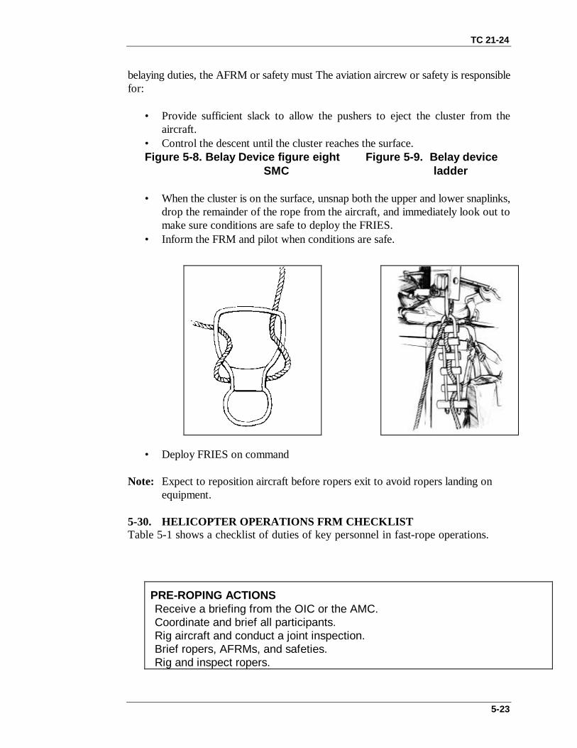
TC 21-24
5-23
belaying duties, the AFRM or safety must The aviation aircrew or safety is responsiblefor:
• Provide sufficient slack to allow the pushers to eject the cluster from theaircraft.
• Control the descent until the cluster reaches the surface.Figure 5-8. Belay Device figure eight Figure 5-9. Belay device
SMC ladder
• When the cluster is on the surface, unsnap both the upper and lower snaplinks,drop the remainder of the rope from the aircraft, and immediately look out tomake sure conditions are safe to deploy the FRIES.
• Inform the FRM and pilot when conditions are safe.
• Deploy FRIES on command
Note: Expect to reposition aircraft before ropers exit to avoid ropers landing on equipment.
5-30. HELICOPTER OPERATIONS FRM CHECKLISTTable 5-1 shows a checklist of duties of key personnel in fast-rope operations.
PRE-ROPING ACTIONSReceive a briefing from the OIC or the AMC.Coordinate and brief all participants.Rig aircraft and conduct a joint inspection.Brief ropers, AFRMs, and safeties.Rig and inspect ropers.
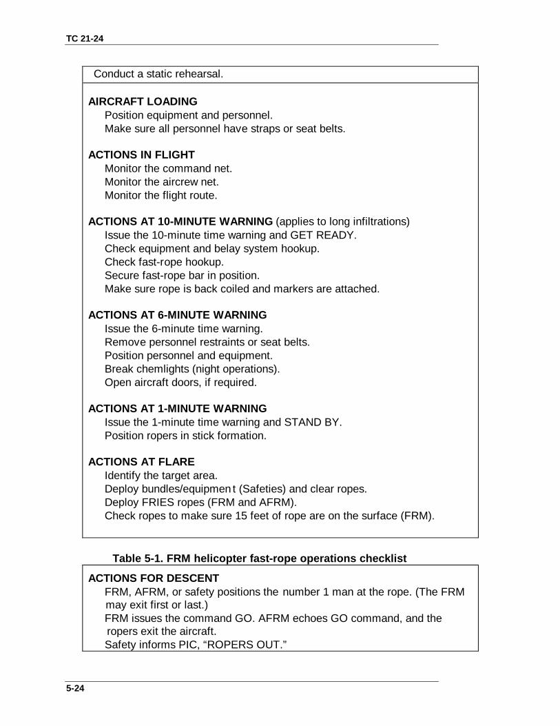
TC 21-24
5-24
Conduct a static rehearsal.
AIRCRAFT LOADINGPosition equipment and personnel.Make sure all personnel have straps or seat belts.
ACTIONS IN FLIGHTMonitor the command net.Monitor the aircrew net.Monitor the flight route.
ACTIONS AT 10-MINUTE WARNING (applies to long infiltrations)Issue the 10-minute time warning and GET READY.Check equipment and belay system hookup.Check fast-rope hookup.Secure fast-rope bar in position.Make sure rope is back coiled and markers are attached.
ACTIONS AT 6-MINUTE WARNINGIssue the 6-minute time warning.Remove personnel restraints or seat belts.Position personnel and equipment.Break chemlights (night operations).Open aircraft doors, if required.
ACTIONS AT 1-MINUTE WARNINGIssue the 1-minute time warning and STAND BY.Position ropers in stick formation.
ACTIONS AT FLAREIdentify the target area.Deploy bundles/equipmen t (Safeties) and clear ropes.Deploy FRIES ropes (FRM and AFRM).Check ropes to make sure 15 feet of rope are on the surface (FRM).
Table 5-1. FRM helicopter fast-rope operations checklist
ACTIONS FOR DESCENT∼ FRM, AFRM, or safety positions the number 1 man at the rope. (The FRM may exit first or last.)∼ FRM issues the command GO. AFRM echoes GO command, and the ropers exit the aircraft.
Safety informs PIC, “ROPERS OUT.”

TC 21-24
5-25
AFRM or safety controls the rate of exit of the ropers.AFRM exits last.Aircrew or safeties observe the last roper. Safety tells the PIC, ALLROPERS AWAY, after the last roper is on the surface and signals.PIC issues command JETTISON or RECOVER ROPES.Aircrew or safety jettisons or recovers ropes, and issues ROPES CLEARreport to the pilot.
Table 5-1. FRM helicopter fast-rope operations checklist (continued).
5-31. FRIES COMMANDS AND SIGNALSThe following standardized arm-and-hand signals are provided for FRIES operations.Ground-to-aircraft arm-and-hand signals are military standard as found in the Pathfinderfield manual 57-38.
a. Time warnings (10-, 6-, and 1-minute) are given by holding up the appropriatenumber of fingers and verbally sounding off.
b. The signal for GET READY is the same as the standard Airborne signal— armsextended horizontally, fingers extended vertically and joined.
c. The signal for STAND-BY is arms extended downward at a 45-degree anglefrom the body with hands closed except for index fingers, which are extended, pointingto the floor
d. To execute the signal for DEPLOY ROPES, the FRM or safety forms bothhands into fists at mid-thigh level and sweeps arms horizontally outward. At fullextension, he opens his hands as if dropping the ropes out of the helicopter and soundsoff with DEPLOY ROPES.
e. The signal for GO is arms raised to horizontal, hands closed with index fingersextended pointing to the ropes.
f. The signal for STOP or ABORT is hands closed into fists with arms raisedacross the forehead .
g. The signal for SIT-DOWN and DON SEAT BELTS is pointing to the floor,followed by moving both fists around waist, as if donning a belt.
h. The signal for OK is hands raised to eye level, index finger and thumb forminga circle with other fingers extended.
Section IX. EMERGENCY ACTIONSProcedures for correcting an emergency condition that could reasonably be encounteredare described in this section. Multiple emergencies, adverse weather, or other unusualconditions may require modification of these procedures. The nature and severity of theemergency dictate the response necessary; therefore, personnel must use soundjudgment in determining the correct action to be taken.

TC 21-24
5-26
5-32. EMERGENCIES BEFORE ROPING STARTSAll personnel sit down, don their seat belts, and take further instructions from the pilotor crew chief.
5-33. EMERGENCIES AFTER ROPING STARTSEmergency procedures to be followed after roping starts are discussed in this paragraph.a. Unsafe Drift or Premature Liftoff. Anyone who detects the aircraft having driftedoff the site must immediately stop training and inform the FRM, AFRM , safety, or PIC.
(1) The FRM, AFRM, safety, or roper stops stick.(2) The ropers stop descent and lock in.(3) The FRM or crewman informs the PIC, and guides him in moving the aircraft
back on target.(4) The unit continues operations.
b. Rope Hung or Snagged (On Ground, Tree, Building). Anyone who detects therope being snagged or hung must immediately stop training and inform the FRM,AFRM, safety, crew chief, or PIC.
(1) The safety ensures ropers are off the rope and are clear.(2) The aircraft descends or lands as needed.(3) The safety frees the rope and informs the pilot.(4) The unit resumes the operation.
c. Lost Communications. All training and operations must be planned to include theuse of the intercom between the PIC or crewmen and the FRM. If the intercom fails, thefollowing arm-and-hand signals can be used until the rope can be cleared and theintercom is restored.
• Wrists crossed diagonally above the forehead with clenched fists to signal stopstick.
• Finger pointed toward the exit and a verbal GO to signal ropers to exit.• Open palm moved and faced in the required direction to signal aircraft
movement.• Clenched fist to stop aircraft movement.
Note: Training will not be conducted without radio communications between the pilots or aircrew and the FRM and the ground.
Section X. SAFETYSafety is everyone’s responsibility. All personnel involved in FRIES operations areresponsible for identifying hazardous situations and preventing injuries to personnel.Anyone who observes an unsafe condition or act is authorized to halt the operation andinform the FRM or the PIC.
5-34. PREFLIGHT AND INFLIGHTAnyone who detects an inflight emergency will immediately notify the PIC, crew chief,or safety and follow aircrew instructions.

TC 21-24
5-27
a. Before a FRIES operation, the FRM will coordinate with the PIC both routineand emergency procedures as well as any unique conditions or potential problems. Healso discusses the procedures to be used during flight, during roping, and before theaircraft’s departure from the roping site. The FRM then discusses the information withall the AFRMs, safeties, and crew chiefs as well. He reviews the time warnings(including arm-and-hand signals) and appropriate actions such as who will deploy ropes,verify rope status, and perform rope-clearing procedures.
b. The mission prebrief covers any aircraft equipment that, if disturbed, could causean aircraft or fast-rope problem. The problem areas should be made known to allpersonnel concerned and preventive measures taken to neutralize or eliminate themwhere possible.
c. The FRM gives the crew chief the final position adjustment over the target,using hand signals.
d. All safety straps and communications cords that are not in use are securelystowed. All safety straps and communication cords in use should be positioned so theydo not present a hazard to personnel movement in the aircraft.
e. After the PIC gives the command DEPLOY ROPES, the FRM is responsiblefor deploying the rope and making sure it is in contact with the surface before ropersexit.
Note: The safety is responsible for observing rope and ropers and for making sure thepilot maintains aircraft position until all ropers are on the surface.
CAUTIONAccording to AR 95-3, anytime operations occur over water, allpersonnel will wear an approved personal flotation device asidentified in FM 57-220 or USASOC Regulation 350-2.
5-35. DURING ROPINGThe following safety procedures apply during roping.
a. During the actual descent, fast-ropers will not use NVGs because they limitdepth perception and create a tunnel vision effect.
b. During descent, ropers must watch for obstructions and lower ropers, and mustbreak as necessary.
c. Individual ropers will lock in during emergencies by wrapping one leg aroundthe rope once or twice and standing on the fast rope with the other foot.
d. Ropers must maintain sufficient intervals on the rope to prevent contact withlower ropers. Individual ropers exit when the head of the man in front of themdisappears below the ramp.
e. Ropers execute descents at speeds commensurate with their experience andproficiency in FRIES infiltration operations. (For example, less-experienced ropersshould descend slowly until they become more proficient.)
f. The number of ropers on each rope at one time must not exceed the safe limitof the rope mount point in use, as follows:

TC 21-24
5-28
(1) Do not exceed 1,500 pounds per rope on the MH/UH-60.(2) Do not exceed 1,500 pounds per rope on the MH/UH-47.(3) Do not exceed 1,500 pounds per rope on the MH/UH-53.(4) Do not exceed 1,300 pounds per rope on the MH-60G.
5-36. SAFETY BRIEFINGAll units must present a safety briefing before conducting FRIES training or operations.The safety briefing must cover the following (as a minimum):
• The planned event (day or night, tower or helicopter, high or low hover,insertion or extraction).
• Actions on the aircraft (or tower).• Operation (or training) location and any hazards within 500 meters.• Identification of key personnel, their location, and their duties.• FRIES equipment and its characteristics.• FRIES equipment rigging or inspection.• Roping personnel preparation (shirttails tucked in, chin strap fastened, loose
straps taped, gloves and goggles on).• Arm-and-hand signals.• Emergencies and emergency procedures.• Medical procedures (medic with aid bags, backboards, litters, and dedicated
vehicle with driver on site).• Communications requirements (frequencies, call signs, required reports).• Any other information essential to safety.
5-37. SAFETY REMINDERSThe following safety reminders will be reviewed by all key personnel before conductingoperations.
a. Ropers must wear long-sleeve shirts or jackets, full-length pants, laced boots,helmets, protective goggles, and heavy leather gloves.
b. MILES harnesses must not be worn during fast-roping.c. Ropers will not wear NVGs.d. Commanders must personally approve the rope site selected for night
operations. The FRIES site must be large enough to permit all ropers, upon reachingthe surface, to move clear of the rope and for units to consolidate or re-form.
e. All night rope operations must be assessed as medium risk or higher.f. FRIES descent training is not authorized with a fast rope longer than 90 feet.g. Ropers must not carry more than 50 pounds of equipment during FRIES
descents. The maximum weight of rucksacks is limited to 35 pounds. When rucksacksexceed 35 pounds (or total load exceeds 50 pounds), gear must be lowered (belayed)on a separate system, preferably from the opposite door.
h. Ropers will not carry bulky equipment that could interfere with FRIESoperations. Equipment that cannot be carried by the soldier during roping (due to itsweight or bulk) can be lowered (belayed) during insertion. During extractions,rucksacks must be attached to the extraction loops of the FRIES rope using snaplinks.

TC 21-24
5-29
i. Ropers must not make more than 6 combat equipment descents or a total of 10descents in a 24-hour period.
j. FRIES training must not be conducted if—
• The aircraft is unstable.• The fast rope is not fully deployed (15 feet of the rope must be on the
surface).• Any obstacle is present that could interfere with the descent of the ropers.• The rope is frozen or slippery• Anyone identifies any unsafe condition.
k. Safety personnel must—
• Position themselves so they can observe active FRIES points with outobstructing ropers.
• Conduct final rigging checks of the mount, equipment, and ropes at the 10-minute warning.
• Ensure the aircraft is over the target area and the ropes reach the ground.• Constantly keep both the PIC and FRM informed—
— When the aircraft is in position for deployment.— When anything is being deployed from the helicopter (ropes, bundles or
personnel).— When 15 feet of rope are on the surface.— When the first roper exits on the fast rope.— When all ropers on the surface are clear.— When the ropes are recovered or jettisoned.— When the aircraft is cleared for flight.— When 15 feet of the extraction rope is on the surface.— When extraction personnel are attached to the rope and ready for lift off.— When extracted personnel are safely lowered to the ground.— When extracted personnel are out from under the aircraft.— Any other conditions that could impact safe operations.
Note: If the FRM and the safety exit, the crew chief performs rope clearing and or jettisoning duties.
WARNINGUsing the word CLEAR tells pilots the aircraft is ready to fly.Before any use of the word CLEAR, FRMs and safeties mustensure that all personnel are well away from the ropes and theropes have been fully recovered or released (during insertion), or all personnel are securely attached to the ropes (duringextraction).

TC 21-24
5-30
l. FRIES training must not be conducted in densely wooded areas or areas proneto blowing dust, sand, or snow, which can produce a hazard for ropers or the aircraft.
m. FRIES training and operations must not be conducted during severe weathersuch as rain, sleet, ice, or extreme cold.
n. The possibility of personnel injury during FRIES training and operations isalways present. Every soldier involved in FRIES activities must maintain constantvigilance to prevent personnel injury and equipment damage.
6-1
CHAPTER 6
EQUIPMENT
This chapter discusses the basic equipment used for rappellingoperations (Appendix B). It covers the types of ropes, the procedures forrope selection, and the care for each rope type. It also discusses the twomethods of coiling and the different snaplinks used to join the equipmentand rope.
Section I. ROPESRopes are the most important items of equipment for the rappeller. They provide accessdown the obstacle or aerial platform, while ensuring individual safety.
6-1. TYPES OF ROPESTwo types of ropes are available to the rappeller— static and dynamic.
a. Static Rope. This rope allows for minimal stretch of the rope. The static ropestretches about 5 to 15 percent at the point of failure and about 2 percent under a workingload. The minimum tensile strength for an 11-mm (7/16-inch) static rope for military useis 4,500 pounds. Kernmantle static ropes range from 3 millimeters to 11 millimeters indiameter and are constructed similar to the 550-parachute cord. (Kern means core andmantle means sheath.) The internal core of the rope is constructed of a continuousmultifilament-nylon yarn, which is spun into continuous parallel strands. This internalcore is then covered with a nylon-braided outer sheath. Due to the internal parallel strandconstruction of the static rope, there is less spinning and kinking than with a dynamicrope. Static ropes can be used for slings, harnesses, etriers (stirrups), rappelling, ropeinstallations, hauling lines, and where stretch of the rope is not desired.
b. Dynamic Rope. This rope allows for stretch within the fibers of the rope, whichcan be a disadvantage in rappelling, prusik climbing, and other applications. Dynamicropes are more susceptible to abrasion and wear. They have about a 5 to 10 percentworking stretch. The minimum tensile strength for an 11-mm (7/16-inch) rope formilitary use is 4,500 pounds. Two types of dynamic ropes are nylon-laid and kernmantle:
(1) Nylon-laid ropes. Synthetic fibers are the best climbing and rappelling material.Nylon has become the standard material for climbing ropes and has replaced manila, flax,hemp, and sisal. The military mountaineering critical application rope is constructed in alaid fashion with continuous multifilament-nylon fiber yarn twisted into strands. Threestrands are twisted into a climbing rope of a specific diameter ( Figure 6-1). Nylon-laidropes are easy to inspect for serviceability by twisting the fibers. Laid ropes tend tountwist slightly when under a load, causing kinking and spinning. They are alsosusceptible to abrasion. The following specifications pertain to the standard militarynylon-laid climbing/rappelling rope:
• 36 1/2 meters (120 feet) long.• 11 millimeters (7/16 inch) wide.• At least a 4,500-pound tensile strength.• Right-hand lay.• One-third stretch factor (at point of failure).

TC 21-24
6-2
• May lose as much as 15 percent of its strength when wet.• Weighs 6 pounds when dry.
Figure 6-1. Nylon-laid rope.
(2) Kernmantle ropes. These ropes are similar to their static counterparts in that theyconsist of an inner core and an outer sheath. The core is constructed of continuous twistednylon filaments, which are laid or braided together and enclosed in a tightly braided outersheath. These ropes are well suited for climbing on rock, snow, or ice where a briefelastic stretch of the rope occurs during a fall. They have a stretch of about 40 percent atthe point of failure. The breaking strength is high, and there are no exposed strands forrock crystals to work between to damage the rope ( Figure 6-2). There is less slidingfriction through the snaplink and over other surfaces, since the outer sheath is smooth.Kernmantle ropes are available in many sizes, lengths, stretch factors, tensile strengths,and fall ratings.
Figure 6-2. Kernmantle (core and sheath) rope.
6-2. ROPE SELECTIONRope selection for military operations requires ropes of various types, lengths, anddiameters; and depends on its intended use (static or dynamic), environment (water-repellant), climate, mission (lightweight ropes), and other factors. Static ropes shouldhave minimal stretch; be smooth, flexible, and strong; resist abrasion and cutting; andhave a low-impact force.
a. Laid rope is easier to inspect (by twisting the strands apart to observe the interiorsurfaces), has greater friction in holding knots, and is less expensive than kernmantle

TC 21-24
6-3
ropes. Its disadvantages include: much lower abrasion resistance, extremely high stretchfactor for both static and dynamic loads, greater friction on rock, readiness to kink,tendency to spin a free-hanging rappeller, and greater absorption of water and dirt.
b. Kernmantle rope is easy to work with, has less friction, does not kink easily, andhas less susceptibility to abrasion. The outer sheath protects the internal fibers from dirt,abrasion, and ultraviolet radiation. Its disadvantages are that it is hard to determinedamage to the core fibers, and it is more expensive than laid rope. Kernmantle rope is notreadily identifiable as dynamic or static and must be marked accordingly.
c. Rope diameter and length vary with intended use. A standard diameter for manyuses is 11 millimeters (7/16 inch). For stirrups, utility ropes, and hauling lines, 7millimeters (5/16 inch), which can also be used in double strands, is adequate. Standardsto remember are that the smaller the diameter, the less the tensile strength; but the largerthe diameter, the heavier the rope. The standard lengths are 36 1/2 meters (120 feet), 40meters (135 feet), 45 meters (150 feet), and 50 meters (165 feet). Normally, standardlengths should not be cut. If a nonstandard length is needed, the rope should be precutbefore the mission and clearly marked.
d. A rope should be selected for a specific use. There are different types of ropes forvarious uses. A dynamic rope is designed for climbing, while a static rope is designed forrappelling, rescue operations, load hauling, and rope installations.
WARNINGUsing a rope for other than its intended use could result inpersonal injury or damage to equipment.
6-3. CARE OF ROPESBecause the rope is the rappeller’s lifeline, it requires a great amount of care andmaintenance.
a. Before and after use, the rope should be carefully inspected for excessive wear,cuts, mildew, or rotten spots. If any of these defects are found, the rope is unserviceable.An unserviceable rope is destroyed by cutting it into usable parts. If no sections areusable, the rope is cut into smaller parts and discarded.
b. Ropes should never be spliced together, stepped on, or dragged. This greatlyreduces the tensile strength of the rope.
c. The rope must not come in contact with sharp edges. If this is likely, the areasmust be padded or taped before rappelling.
d. The rope must be kept as dry as possible. If it becomes wet, it must be dried out toprevent rotting. (Avoid excessive heat/heating during the drying process.)

TC 21-24
6-4
6-4. COILINGTwo methods of coiling are the mountaineer’s coil and the farmer’s coil ( Figure 6-3).
a. Mountaineer’s Coil.(1) To use the mountaineer’s coil, grasp the rope about 3 feet from the end with the
left hand. The right hand is then placed next to the left hand and runs along the rope untilboth arms are outstretched. Grasping the rope firmly, bring the hands together to form aloop, which is laid in the left hand. Repeat, forming uniform loops that run in a clockwisedirection until the rope is completely coiled. If the rope tends to twist or form figureeights, give it a slight twist with the right hand when each loop is formed. Coil the rope ina clockwise direction to conform with the lay.
(2) To complete the coil, form a bight about 30 centimeters (12 inches) long with thestarting end of the rope and lay it along the top of the coil. Uncoil the last loop and use itto wrap around the coil and the bight. Wrap toward the closed end of the bight, bindingthe final wrap across itself to lock it in place. Make six to eight wraps to secure the coil.Push the end of the rope down through the closed end of the bight. Carry the running endof the coil either in the pack (by forming a figure eight, doubling it, and placing it underthe flap) or by placing it over the shoulder and under the opposite arm. If the rope to becoiled is anchored as in coiling a belay or rappel lane, start the coil near the end closest tothe anchor so that the kinks work themselves out of the free end.
b. Farmer’s Coil.(1) The farmer’s coil is easier and faster to coil than the mountaineer’s coil. Establish
the center of the rope either by locating its center mark or by grasping both ends of therope and feeding them out until a bight comes up that is the center of the rope. Begincoiling with the doubled rope the same as the mountaineer’s coil method. Leave about 4.6meters (15 feet) of rope uncoiled. Then, squeeze the coils together and make four to sixwraps around the middle of the coil, ensuring that the first wrap is held in place by theother wraps.
(2) Form a bight with the two running ends and place it through the bight formed bythe top of the coil. Then, run the two running ends over the top of the coil and through thebight that is formed. Dress them in the center of the back of the carrier. Run the two endsover the shoulders to form shoulder straps. Then, bring them under the arms, cross themin the back over the coil, bring them around the body of the carrier, and tie them off witha square knot at the stomach.

TC 21-24
6-5
Figure 6-3. Two methods of tying a coil.
Section II. SNAPLINKSSnaplinks are used to join equipment, rope, and people into a functioning system. Whenused properly, they are strong, versatile items. Snaplinks are metal (steel, aluminum, oralloys) loops with a hinged, spring-loaded gate on one side. They come in many sizes,shapes, and strengths (with and without locking gates) and in many types of metal. Steelis the strongest snaplink, but it is heavier.
6-5. DESCRIPTIONSnaplinks are available in many sizes and shapes to suit different needs. A lockingsnaplink is best for rappelling. Nonlocking snaplinks are easy to operate, but should beused only where they cannot be accidentally opened. Hollow snaplinks should be avoidedsince their use is limited. The following information applies to all snaplinks.
a. The weakest part of a snaplink is the gate. The gate must be closed beforeapplying a load. When the gate is open, snaplinks should have little or no lateralmovement of the gate.
b. Locking pins should be checked to ensure that they are not loose, worn, orcorroded.
c. The metal should be checked for any cracks, grooves, burrs, flaws, or rust.d. The spring-loaded gate should automatically close securely from an open to a
closed position with no gap between the locking pin and notch.e. If an engraver is used to mark snaplinks, it should be applied only to the gate,
never to the load-bearing side.
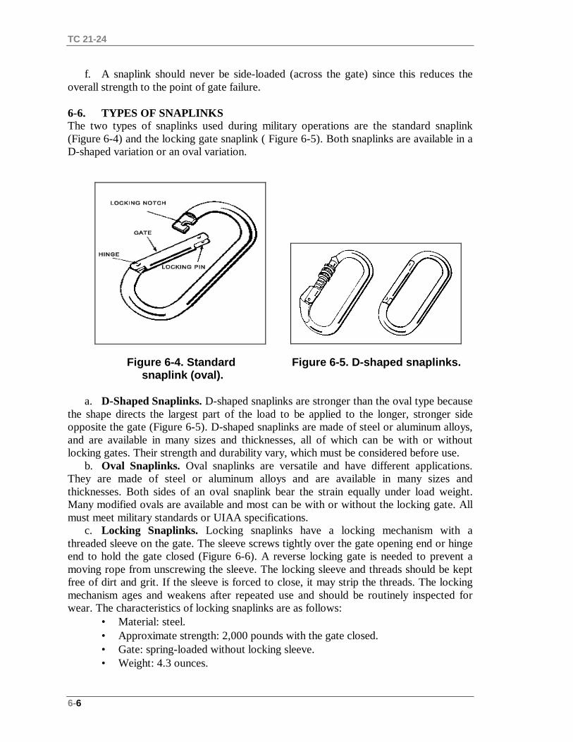
TC 21-24
6-6
f. A snaplink should never be side-loaded (across the gate) since this reduces theoverall strength to the point of gate failure.
6-6. TYPES OF SNAPLINKSThe two types of snaplinks used during military operations are the standard snaplink(Figure 6-4) and the locking gate snaplink ( Figure 6-5). Both snaplinks are available in aD-shaped variation or an oval variation.
Figure 6-4. Standard Figure 6-5. D-shaped snaplinks. snaplink (oval).
a. D-Shaped Snaplinks. D-shaped snaplinks are stronger than the oval type becausethe shape directs the largest part of the load to be applied to the longer, stronger sideopposite the gate (Figure 6-5). D-shaped snaplinks are made of steel or aluminum alloys,and are available in many sizes and thicknesses, all of which can be with or withoutlocking gates. Their strength and durability vary, which must be considered before use.
b. Oval Snaplinks. Oval snaplinks are versatile and have different applications.They are made of steel or aluminum alloys and are available in many sizes andthicknesses. Both sides of an oval snaplink bear the strain equally under load weight.Many modified ovals are available and most can be with or without the locking gate. Allmust meet military standards or UIAA specifications.
c. Locking Snaplinks. Locking snaplinks have a locking mechanism with athreaded sleeve on the gate. The sleeve screws tightly over the gate opening end or hingeend to hold the gate closed (Figure 6-6). A reverse locking gate is needed to prevent amoving rope from unscrewing the sleeve. The locking sleeve and threads should be keptfree of dirt and grit. If the sleeve is forced to close, it may strip the threads. The lockingmechanism ages and weakens after repeated use and should be routinely inspected forwear. The characteristics of locking snaplinks are as follows:
• Material: steel.• Approximate strength: 2,000 pounds with the gate closed.• Gate: spring-loaded without locking sleeve.• Weight: 4.3 ounces.

TC 21-24
6-7
Figure 6-6. Locking snaplink.
6-7. INSPECTIONAll rappelling material and individual rappelling equipment must be inspected beforeconducting a rappelling operation. The rappel master is responsible for ensuring theserviceability of rappelling material and individual rappelling equipment.
a. Snaplinks. Snaplinks should be inspected daily before, during, and after use.(1) The metal should be checked for cracks, grooves, burrs, rust, and flaws. The gate
should open and close freely without binding. There should be no lateral movement whenthe gate is open. The gate spring action should snap shut when released. The lockingnotch should have a slant or slot so that the gate remains shut under the impact of arappeller’s fall. The gate pins should not work their way out of their holes and should notbe shorter than their holes. If there is a locking mechanism, it should be inspected toensure that threads are not stripped and that the sleeve tightly locks the gate.
(2) If burrs, grooves, or rough areas are identified, the snaplink should not be used.Rust should be removed with steel wool and the spot rubbed with oil or solvent. Thespring should be lubricated as needed. The snaplink must be boiled in water for 20 to 30seconds to remove the cleaning agents since solvents and oils cause dirt to cling to thesnaplink and to rub off on the ropes. It is better to use a dry graphite-based lubricant onsnaplinks since such lubricants do not attract dirt.
b. Ropes. The ropes are inspected for serviceability. A rappel rope is unserviceableif it is saturated with petroleum products, is mildewed, shows excessive wear, has softspots (internal damage), or if one strand is cut more than one-half of its diameter. Ropesshould be inspected daily— before, during, and after use. An applicable annotation shouldbe made in a corresponding rope log (DA Form 5752-R) ( Figure 6-7).

TC 21-24
6-8
Figure 6-7. Example of completed DA Form 5752-R.
c. Gloves. The gloves are inspected for serviceability. They are unserviceable ifholes are found in the friction-bearing surfaces or along the seams.
d. Helmet. The helmet is inspected for correct assembly and serviceability. It isunserviceable if it cannot be properly assembled or if any straps are cut or torn one-quarter of its width.
(1) Ensure that the chin strap attaching tabs are secured to the helmet by the lockingnuts.
(2) Ensure that the pull-the-dot tab has four plies of nylon and that the chin strap isrouted from the inside of the buckle around the horizontal bar and back toward the insideof the buckle.
Section III. ALTERNATE METHODS OF DESCENTSnaplinks or carabiners that are used for rappelling are placed through the sewn loops ofthe seat harness or the sewn loops of the seat-chest combination.
6-8. FIGURE-EIGHT DESCENDERThe rappeller attaches a locking carabiner to the harness (Figure 6-8). He routes therappel rope up through the large hole and places the bight over the collar. He inserts thefigure eight with the rappel rope attached into the locking carabiner, and locks it down.The rappeller brakes to the rear and descends as in a seat hip rappel. If heavy loads are tobe descended, he uses a double wrap around the collar.

TC 21-24
6-9
Figure 6-8. Figure-eight descender.
6-9. MUNTER HITCHThe rappeller attaches a large radius snaplink to the harness or rappel seat. He ties aMunter hitch and clip into the snaplink (Figure 6-9, page 6-9). He brakes to the front anddescends with an L-shape body position.
Notes: 1. The guide hand should remain on the standing end of the rope to keep the rappeller’s head and face away from the hardware.
2. The Munter hitch creates significant rope-to-rope friction and may cause premature wear on nylon ropes.
Figure 6-9. Munter hitch.

6-1
CHAPTER 6
EQUIPMENT
This chapter discusses the basic equipment used for rappellingoperations (Appendix B). It covers the types of ropes, the procedures forrope selection, and the care for each rope type. It also discusses the twomethods of coiling and the different snaplinks used to join the equipmentand rope.
Section I. ROPESRopes are the most important items of equipment for the rappeller. They provide accessdown the obstacle or aerial platform, while ensuring individual safety.
6-1. TYPES OF ROPESTwo types of ropes are available to the rappeller— static and dynamic.
a. Static Rope. This rope allows for minimal stretch of the rope. The static ropestretches about 5 to 15 percent at the point of failure and about 2 percent under a workingload. The minimum tensile strength for an 11-mm (7/16-inch) static rope for military useis 4,500 pounds. Kernmantle static ropes range from 3 millimeters to 11 millimeters indiameter and are constructed similar to the 550-parachute cord. (Kern means core andmantle means sheath.) The internal core of the rope is constructed of a continuousmultifilament-nylon yarn, which is spun into continuous parallel strands. This internalcore is then covered with a nylon-braided outer sheath. Due to the internal parallel strandconstruction of the static rope, there is less spinning and kinking than with a dynamicrope. Static ropes can be used for slings, harnesses, etriers (stirrups), rappelling, ropeinstallations, hauling lines, and where stretch of the rope is not desired.
b. Dynamic Rope. This rope allows for stretch within the fibers of the rope, whichcan be a disadvantage in rappelling, prusik climbing, and other applications. Dynamicropes are more susceptible to abrasion and wear. They have about a 5 to 10 percentworking stretch. The minimum tensile strength for an 11-mm (7/16-inch) rope formilitary use is 4,500 pounds. Two types of dynamic ropes are nylon-laid and kernmantle:
(1) Nylon-laid ropes. Synthetic fibers are the best climbing and rappelling material.Nylon has become the standard material for climbing ropes and has replaced manila, flax,hemp, and sisal. The military mountaineering critical application rope is constructed in alaid fashion with continuous multifilament-nylon fiber yarn twisted into strands. Threestrands are twisted into a climbing rope of a specific diameter ( Figure 6-1). Nylon-laidropes are easy to inspect for serviceability by twisting the fibers. Laid ropes tend tountwist slightly when under a load, causing kinking and spinning. They are alsosusceptible to abrasion. The following specifications pertain to the standard militarynylon-laid climbing/rappelling rope:
• 36 1/2 meters (120 feet) long.• 11 millimeters (7/16 inch) wide.• At least a 4,500-pound tensile strength.• Right-hand lay.• One-third stretch factor (at point of failure).
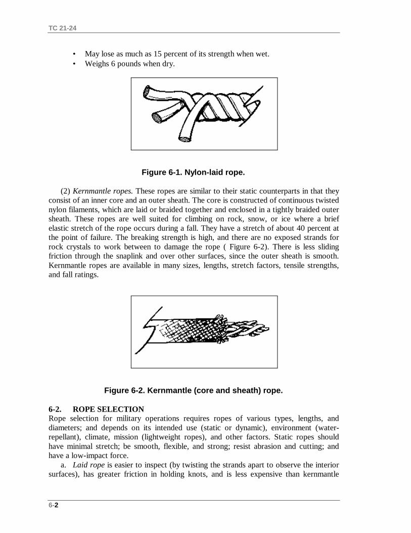
TC 21-24
6-2
• May lose as much as 15 percent of its strength when wet.• Weighs 6 pounds when dry.
Figure 6-1. Nylon-laid rope.
(2) Kernmantle ropes. These ropes are similar to their static counterparts in that theyconsist of an inner core and an outer sheath. The core is constructed of continuous twistednylon filaments, which are laid or braided together and enclosed in a tightly braided outersheath. These ropes are well suited for climbing on rock, snow, or ice where a briefelastic stretch of the rope occurs during a fall. They have a stretch of about 40 percent atthe point of failure. The breaking strength is high, and there are no exposed strands forrock crystals to work between to damage the rope ( Figure 6-2). There is less slidingfriction through the snaplink and over other surfaces, since the outer sheath is smooth.Kernmantle ropes are available in many sizes, lengths, stretch factors, tensile strengths,and fall ratings.
Figure 6-2. Kernmantle (core and sheath) rope.
6-2. ROPE SELECTIONRope selection for military operations requires ropes of various types, lengths, anddiameters; and depends on its intended use (static or dynamic), environment (water-repellant), climate, mission (lightweight ropes), and other factors. Static ropes shouldhave minimal stretch; be smooth, flexible, and strong; resist abrasion and cutting; andhave a low-impact force.
a. Laid rope is easier to inspect (by twisting the strands apart to observe the interiorsurfaces), has greater friction in holding knots, and is less expensive than kernmantle
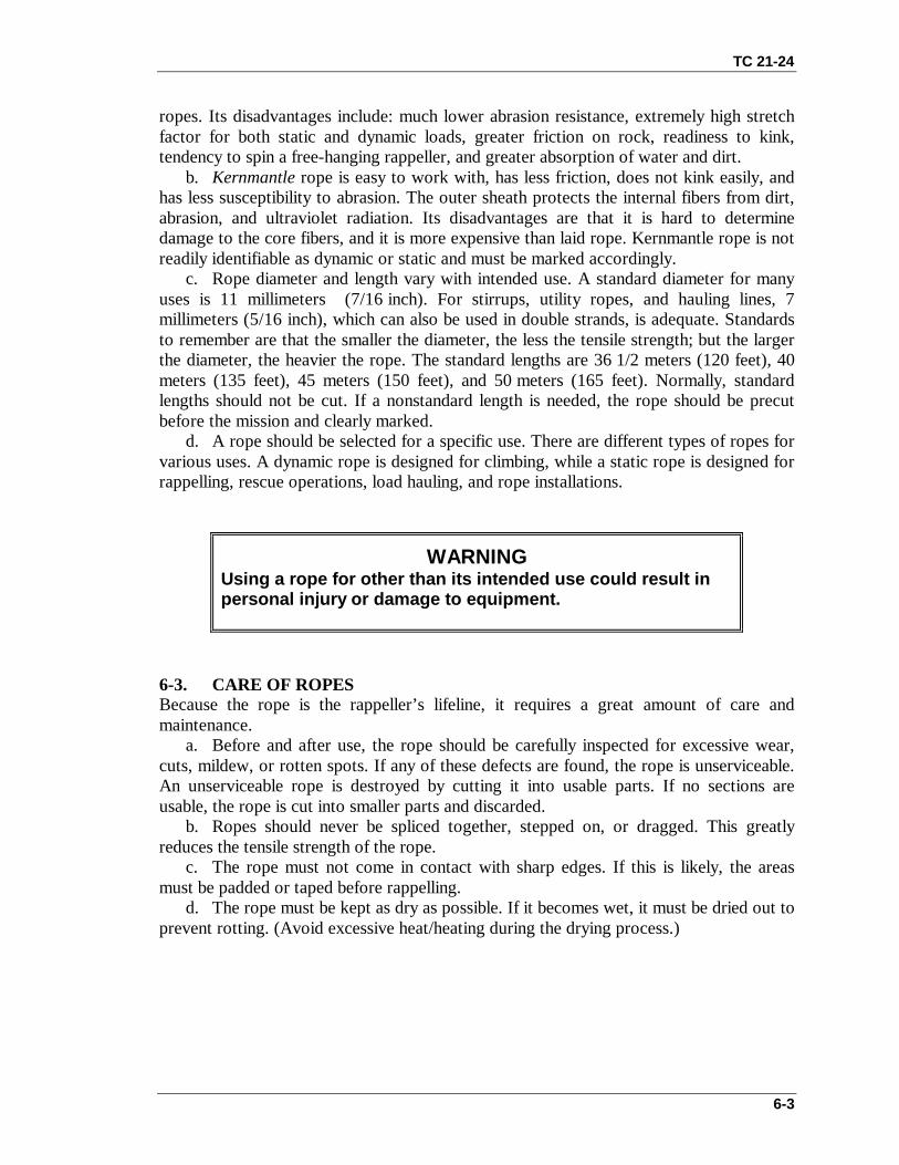
TC 21-24
6-3
ropes. Its disadvantages include: much lower abrasion resistance, extremely high stretchfactor for both static and dynamic loads, greater friction on rock, readiness to kink,tendency to spin a free-hanging rappeller, and greater absorption of water and dirt.
b. Kernmantle rope is easy to work with, has less friction, does not kink easily, andhas less susceptibility to abrasion. The outer sheath protects the internal fibers from dirt,abrasion, and ultraviolet radiation. Its disadvantages are that it is hard to determinedamage to the core fibers, and it is more expensive than laid rope. Kernmantle rope is notreadily identifiable as dynamic or static and must be marked accordingly.
c. Rope diameter and length vary with intended use. A standard diameter for manyuses is 11 millimeters (7/16 inch). For stirrups, utility ropes, and hauling lines, 7millimeters (5/16 inch), which can also be used in double strands, is adequate. Standardsto remember are that the smaller the diameter, the less the tensile strength; but the largerthe diameter, the heavier the rope. The standard lengths are 36 1/2 meters (120 feet), 40meters (135 feet), 45 meters (150 feet), and 50 meters (165 feet). Normally, standardlengths should not be cut. If a nonstandard length is needed, the rope should be precutbefore the mission and clearly marked.
d. A rope should be selected for a specific use. There are different types of ropes forvarious uses. A dynamic rope is designed for climbing, while a static rope is designed forrappelling, rescue operations, load hauling, and rope installations.
WARNINGUsing a rope for other than its intended use could result inpersonal injury or damage to equipment.
6-3. CARE OF ROPESBecause the rope is the rappeller’s lifeline, it requires a great amount of care andmaintenance.
a. Before and after use, the rope should be carefully inspected for excessive wear,cuts, mildew, or rotten spots. If any of these defects are found, the rope is unserviceable.An unserviceable rope is destroyed by cutting it into usable parts. If no sections areusable, the rope is cut into smaller parts and discarded.
b. Ropes should never be spliced together, stepped on, or dragged. This greatlyreduces the tensile strength of the rope.
c. The rope must not come in contact with sharp edges. If this is likely, the areasmust be padded or taped before rappelling.
d. The rope must be kept as dry as possible. If it becomes wet, it must be dried out toprevent rotting. (Avoid excessive heat/heating during the drying process.)
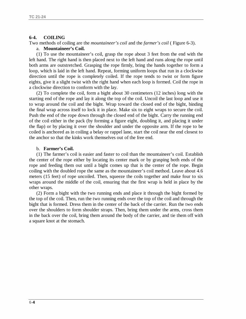
TC 21-24
6-4
6-4. COILINGTwo methods of coiling are the mountaineer’s coil and the farmer’s coil ( Figure 6-3).
a. Mountaineer’s Coil.(1) To use the mountaineer’s coil, grasp the rope about 3 feet from the end with the
left hand. The right hand is then placed next to the left hand and runs along the rope untilboth arms are outstretched. Grasping the rope firmly, bring the hands together to form aloop, which is laid in the left hand. Repeat, forming uniform loops that run in a clockwisedirection until the rope is completely coiled. If the rope tends to twist or form figureeights, give it a slight twist with the right hand when each loop is formed. Coil the rope ina clockwise direction to conform with the lay.
(2) To complete the coil, form a bight about 30 centimeters (12 inches) long with thestarting end of the rope and lay it along the top of the coil. Uncoil the last loop and use itto wrap around the coil and the bight. Wrap toward the closed end of the bight, bindingthe final wrap across itself to lock it in place. Make six to eight wraps to secure the coil.Push the end of the rope down through the closed end of the bight. Carry the running endof the coil either in the pack (by forming a figure eight, doubling it, and placing it underthe flap) or by placing it over the shoulder and under the opposite arm. If the rope to becoiled is anchored as in coiling a belay or rappel lane, start the coil near the end closest tothe anchor so that the kinks work themselves out of the free end.
b. Farmer’s Coil.(1) The farmer’s coil is easier and faster to coil than the mountaineer’s coil. Establish
the center of the rope either by locating its center mark or by grasping both ends of therope and feeding them out until a bight comes up that is the center of the rope. Begincoiling with the doubled rope the same as the mountaineer’s coil method. Leave about 4.6meters (15 feet) of rope uncoiled. Then, squeeze the coils together and make four to sixwraps around the middle of the coil, ensuring that the first wrap is held in place by theother wraps.
(2) Form a bight with the two running ends and place it through the bight formed bythe top of the coil. Then, run the two running ends over the top of the coil and through thebight that is formed. Dress them in the center of the back of the carrier. Run the two endsover the shoulders to form shoulder straps. Then, bring them under the arms, cross themin the back over the coil, bring them around the body of the carrier, and tie them off witha square knot at the stomach.

TC 21-24
6-5
Figure 6-3. Two methods of tying a coil.
Section II. SNAPLINKSSnaplinks are used to join equipment, rope, and people into a functioning system. Whenused properly, they are strong, versatile items. Snaplinks are metal (steel, aluminum, oralloys) loops with a hinged, spring-loaded gate on one side. They come in many sizes,shapes, and strengths (with and without locking gates) and in many types of metal. Steelis the strongest snaplink, but it is heavier.
6-5. DESCRIPTIONSnaplinks are available in many sizes and shapes to suit different needs. A lockingsnaplink is best for rappelling. Nonlocking snaplinks are easy to operate, but should beused only where they cannot be accidentally opened. Hollow snaplinks should be avoidedsince their use is limited. The following information applies to all snaplinks.
a. The weakest part of a snaplink is the gate. The gate must be closed beforeapplying a load. When the gate is open, snaplinks should have little or no lateralmovement of the gate.
b. Locking pins should be checked to ensure that they are not loose, worn, orcorroded.
c. The metal should be checked for any cracks, grooves, burrs, flaws, or rust.d. The spring-loaded gate should automatically close securely from an open to a
closed position with no gap between the locking pin and notch.e. If an engraver is used to mark snaplinks, it should be applied only to the gate,
never to the load-bearing side.

TC 21-24
6-6
f. A snaplink should never be side-loaded (across the gate) since this reduces theoverall strength to the point of gate failure.
6-6. TYPES OF SNAPLINKSThe two types of snaplinks used during military operations are the standard snaplink(Figure 6-4) and the locking gate snaplink ( Figure 6-5). Both snaplinks are available in aD-shaped variation or an oval variation.
Figure 6-4. Standard Figure 6-5. D-shaped snaplinks. snaplink (oval).
a. D-Shaped Snaplinks. D-shaped snaplinks are stronger than the oval type becausethe shape directs the largest part of the load to be applied to the longer, stronger sideopposite the gate (Figure 6-5). D-shaped snaplinks are made of steel or aluminum alloys,and are available in many sizes and thicknesses, all of which can be with or withoutlocking gates. Their strength and durability vary, which must be considered before use.
b. Oval Snaplinks. Oval snaplinks are versatile and have different applications.They are made of steel or aluminum alloys and are available in many sizes andthicknesses. Both sides of an oval snaplink bear the strain equally under load weight.Many modified ovals are available and most can be with or without the locking gate. Allmust meet military standards or UIAA specifications.
c. Locking Snaplinks. Locking snaplinks have a locking mechanism with athreaded sleeve on the gate. The sleeve screws tightly over the gate opening end or hingeend to hold the gate closed (Figure 6-6). A reverse locking gate is needed to prevent amoving rope from unscrewing the sleeve. The locking sleeve and threads should be keptfree of dirt and grit. If the sleeve is forced to close, it may strip the threads. The lockingmechanism ages and weakens after repeated use and should be routinely inspected forwear. The characteristics of locking snaplinks are as follows:
• Material: steel.• Approximate strength: 2,000 pounds with the gate closed.• Gate: spring-loaded without locking sleeve.• Weight: 4.3 ounces.
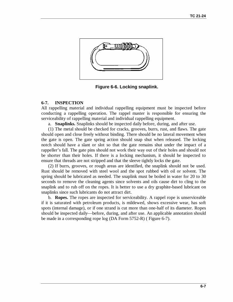
TC 21-24
6-7
Figure 6-6. Locking snaplink.
6-7. INSPECTIONAll rappelling material and individual rappelling equipment must be inspected beforeconducting a rappelling operation. The rappel master is responsible for ensuring theserviceability of rappelling material and individual rappelling equipment.
a. Snaplinks. Snaplinks should be inspected daily before, during, and after use.(1) The metal should be checked for cracks, grooves, burrs, rust, and flaws. The gate
should open and close freely without binding. There should be no lateral movement whenthe gate is open. The gate spring action should snap shut when released. The lockingnotch should have a slant or slot so that the gate remains shut under the impact of arappeller’s fall. The gate pins should not work their way out of their holes and should notbe shorter than their holes. If there is a locking mechanism, it should be inspected toensure that threads are not stripped and that the sleeve tightly locks the gate.
(2) If burrs, grooves, or rough areas are identified, the snaplink should not be used.Rust should be removed with steel wool and the spot rubbed with oil or solvent. Thespring should be lubricated as needed. The snaplink must be boiled in water for 20 to 30seconds to remove the cleaning agents since solvents and oils cause dirt to cling to thesnaplink and to rub off on the ropes. It is better to use a dry graphite-based lubricant onsnaplinks since such lubricants do not attract dirt.
b. Ropes. The ropes are inspected for serviceability. A rappel rope is unserviceableif it is saturated with petroleum products, is mildewed, shows excessive wear, has softspots (internal damage), or if one strand is cut more than one-half of its diameter. Ropesshould be inspected daily— before, during, and after use. An applicable annotation shouldbe made in a corresponding rope log (DA Form 5752-R) ( Figure 6-7).

TC 21-24
6-8
Figure 6-7. Example of completed DA Form 5752-R.
c. Gloves. The gloves are inspected for serviceability. They are unserviceable ifholes are found in the friction-bearing surfaces or along the seams.
d. Helmet. The helmet is inspected for correct assembly and serviceability. It isunserviceable if it cannot be properly assembled or if any straps are cut or torn one-quarter of its width.
(1) Ensure that the chin strap attaching tabs are secured to the helmet by the lockingnuts.
(2) Ensure that the pull-the-dot tab has four plies of nylon and that the chin strap isrouted from the inside of the buckle around the horizontal bar and back toward the insideof the buckle.
Section III. ALTERNATE METHODS OF DESCENTSnaplinks or carabiners that are used for rappelling are placed through the sewn loops ofthe seat harness or the sewn loops of the seat-chest combination.
6-8. FIGURE-EIGHT DESCENDERThe rappeller attaches a locking carabiner to the harness (Figure 6-8). He routes therappel rope up through the large hole and places the bight over the collar. He inserts thefigure eight with the rappel rope attached into the locking carabiner, and locks it down.The rappeller brakes to the rear and descends as in a seat hip rappel. If heavy loads are tobe descended, he uses a double wrap around the collar.

TC 21-24
6-9
Figure 6-8. Figure-eight descender.
6-9. MUNTER HITCHThe rappeller attaches a large radius snaplink to the harness or rappel seat. He ties aMunter hitch and clip into the snaplink (Figure 6-9, page 6-9). He brakes to the front anddescends with an L-shape body position.
Notes: 1. The guide hand should remain on the standing end of the rope to keep the rappeller’s head and face away from the hardware.
2. The Munter hitch creates significant rope-to-rope friction and may cause premature wear on nylon ropes.
Figure 6-9. Munter hitch.

7-1
CHAPTER 7
KNOTS
A knot is a fastening made by intertwining or tying pieces of string,cord, rope, or webbing. All knots used by a rappeller are divided into fourclasses: Class I— joining knots, Class II— anchor knots, Class III— middlerope knots, and Class IV— special knots. These classes of knots areintended only as a general guide since some of the knots discussed hereinmay be appropriate in more than one class. The skill of knot tying may belost if it is not used and practiced. With experience and practice, knottying becomes instinctive and helps the soldier in many situations.
7-1. MILITARY MOUNTAINEERING TERMINOLOGYThe terms explained below are the most commonly used in military mountaineering(Figure 7-1).
a. A bight of rope is a simple bend of rope in which the rope does not cross itself.b. A loop is a bend of rope in which the rope does cross itself.c. A half hitch is a loop that runs around an object and locks itself.d. The running end (working end) of the rope is the free end of the rope that can be
used.e. The standing part of the rope is the part that is static (anchored, coiled); the
remaining part of the rope not being used (also called static end).f. The lay of the rope is the same as the twist of the rope.g. A round turn is a single complete wrap of the rope around an object providing
360-degree contact. The running end leaves the completed circle in the same direction asthe standing part. In a round turn, the rope is wrapped around an object 1 1/2 times.
h. The pigtail is the short length of rope remaining at the end after tying a knot orcoiling a rope.
i. Back feeding (or stacking) is taking off one wrap at a time from a coil, and lettingit fall naturally to the ground.
j. Dress down the knot is tightening down a knot to its functioning form.k. An overhand is a loop with the running end pulled through the loop.
Figure 7-1. Examples of rope terminology.
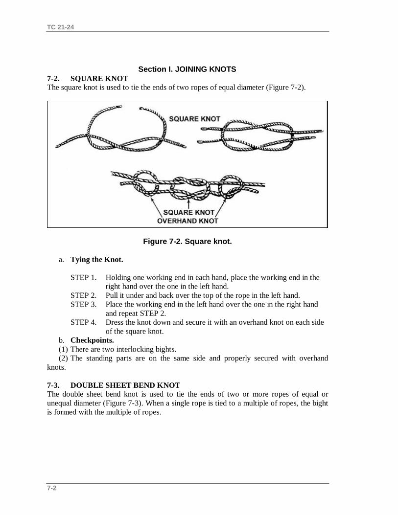
TC 21-24
7-2
Section I. JOINING KNOTS7-2. SQUARE KNOTThe square knot is used to tie the ends of two ropes of equal diameter (Figure 7-2).
Figure 7-2. Square knot.
a. Tying the Knot.
STEP 1. Holding one working end in each hand, place the working end in the right hand over the one in the left hand.
STEP 2. Pull it under and back over the top of the rope in the left hand.STEP 3. Place the working end in the left hand over the one in the right hand
and repeat STEP 2.STEP 4. Dress the knot down and secure it with an overhand knot on each side
of the square knot.b. Checkpoints.(1) There are two interlocking bights.(2) The standing parts are on the same side and properly secured with overhand
knots.
7-3. DOUBLE SHEET BEND KNOTThe double sheet bend knot is used to tie the ends of two or more ropes of equal orunequal diameter (Figure 7-3). When a single rope is tied to a multiple of ropes, the bightis formed with the multiple of ropes.

TC 21-24
7-3
Figure 7-3. Double sheet bend knot.
a. Tying the Knot.
STEP 1. Form a 30-centimeter (12-inch) bight in the left hand with the rope or ropes. Ensure that the short end of the bight is facing to the inside.
STEP 2. Place the index finger of the left hand on top of the bight. Bring the rope in the right hand up through the bight and over the index finger ofthe left hand, so the working end is away from the body.
STEP 3. Reach through the loop and grasp the working end of the rope and bring it back towards the body. Place it between the index finger and the bight, forming a round turn. Repeat this one more time, wrapping toward the tip of the index finger.
STEP 4. Remove the finger and dress the knot down.
b. Checkpoints.(1) The two wraps around the bight are held in place by a locking bar.(2) The two standing parts of the ropes exit parallel and from opposite ends of the
knot. The two working ends form an L and exit the knot at a 90-degree angle and onopposite sides of the knot.
7-4. FISHERMAN’S KNOTThe fisherman’s knot is used to tie two ropes of similar or dissimilar materials (Figure 7-4).
Figure 7-4. Fisherman’s knot.

TC 21-24
7-4
a. Tying the Knot.
STEP 1. Tie an overhand knot in one end of the rope.STEP 2. Pass the working end of the other rope through the first overhand knot.
Tie an overhand knot around the standing part of the first rope with the working end of the second rope.
STEP 3. Tightly dress down each overhand knot and tightly draw the knots together.
b. Checkpoints.(1) The two separate overhand knots are tied tightly around the long standing part of
the opposing rope.(2) The two overhand knots are drawn snug.
7-5. DOUBLE FISHERMAN’S KNOTThe double fisherman’s knot (also called double English or grapevine) is used to tie tworopes of similar or dissimilar materials (Figure 7-5).
Figure 7-5. Double fisherman’s knot.
a. Tying the Knot.
STEP 1. With the working end of one rope, tie two wraps around the standing part of another rope.
STEP 2. Insert the working end (STEP 1) back through the two wraps and drawit tight.

TC 21-24
7-5
STEP 3. With the working end of the other rope, which contains the standing part (STEPS 1 and 2), tie two wraps around the standing part of the other rope (the working end in STEP 1). Insert the working end back through the two wraps and draw tight.
STEP 4. Pull on the opposing ends to bring the two knots together.
b. Checkpoints.(1) Two wraps with the working end running through and drawn tight.(2) Both wraps are drawn together with all the slack out of the knot.
7-6. WATER KNOTThe water knot is used to attach two webbing ends (Figure 7-6). It is also called a ringbend, overhand retrace, or tape knot. It is used in runners and harnesses.
Figure 7-6. Water knot
a. Tying the Knot.
STEP 1. Tie an overhand knot in one of the ends.STEP 2. Feed the other end back through the knot, following the path of the
first rope in reverse.
b. Checkpoints.(1) There are two overhand knots, one retracing the other.(2) There is no slack in the knot, with the working ends coming out of the knot in
opposite directions (at least 5 centimeters [2 inches] long).

TC 21-24
7-6
Section II. ANCHOR KNOTS
7-7. BOWLINE KNOTThe bowline knot is used to tie a single fixed loop in the end of a rope (Figure 7-7). Itdoes not slip under strain and is easily untied. This knot is always used when there isalternating tension. It can also be used to tie the end of a rope to an anchor.
Figure 7-7. Bowline knot.a. Tying the Knot.
STEP 1. Bring the working end of the rope around the anchor, from right to left(as the rappeller faces the anchor).
STEP 2. Form an overhand loop in the standing part of the rope (on the rappeller’s right) toward the anchor.
STEP 3. Reach through the loop and pull up a bight.STEP 4. Place the working end of the rope (on the rappeller’s left) through the
bight, and bring it back onto itself. Dress the knot down.STEP 5. Form an overhand knot with the tail from the bight.
b. Checkpoints.(1) The loop is locked into place by a bight.(2) The short portion of the bight is on the inside and on the loop around the anchor
(or inside the fixed loop).
7-8. ROUND TURN AND TWO HALF HITCHES KNOTThe round turn and twohalf hitches knot is used to tie the end of a rope to an anchor and must have constanttension (Figure 7-8).

TC 21-24
7-7
Figure 7-8. Round turn and two half hitches knot.
a.Tying the Knot.
STEP 1. Route the rope around the anchor from right to left and wrap down (must have two wraps in the rear of the anchor and one in the front). Run the loop around the object to provide 360-degree contact, distributing the load over the anchor.
STEP 2. Bring the working end of the rope left to right and over the standing part, forming a half hitch (first half hitch).
STEP 3. Repeat STEP 2 (last half hitch has a 15-centimeter [6-inch] pigtail).STEP 4. Dress the knot down.
b. Checkpoints.(1) A complete round turn should exist around the anchor with no crosses.(2) Two half hitches should be held in place by a locking bar with no less than a
15-centimeter (6-inch) tail remaining.(3) When the two half hitches are twisted to the left or the right, they will appear to
for a figure eight.(4) Looking at the top of the half hitches, the rope should appear to be one continuous
rope.
7-9. FIGURE-EIGHT RETRACE KNOTThe figure-eight retrace knot is also called a rerouted figure eight. Although it producesthe same result as a figure-eight loop, by tying the knot in a retrace it can be used tofasten the rope to trees or to places where the loop cannot be used (Figure 7-9).
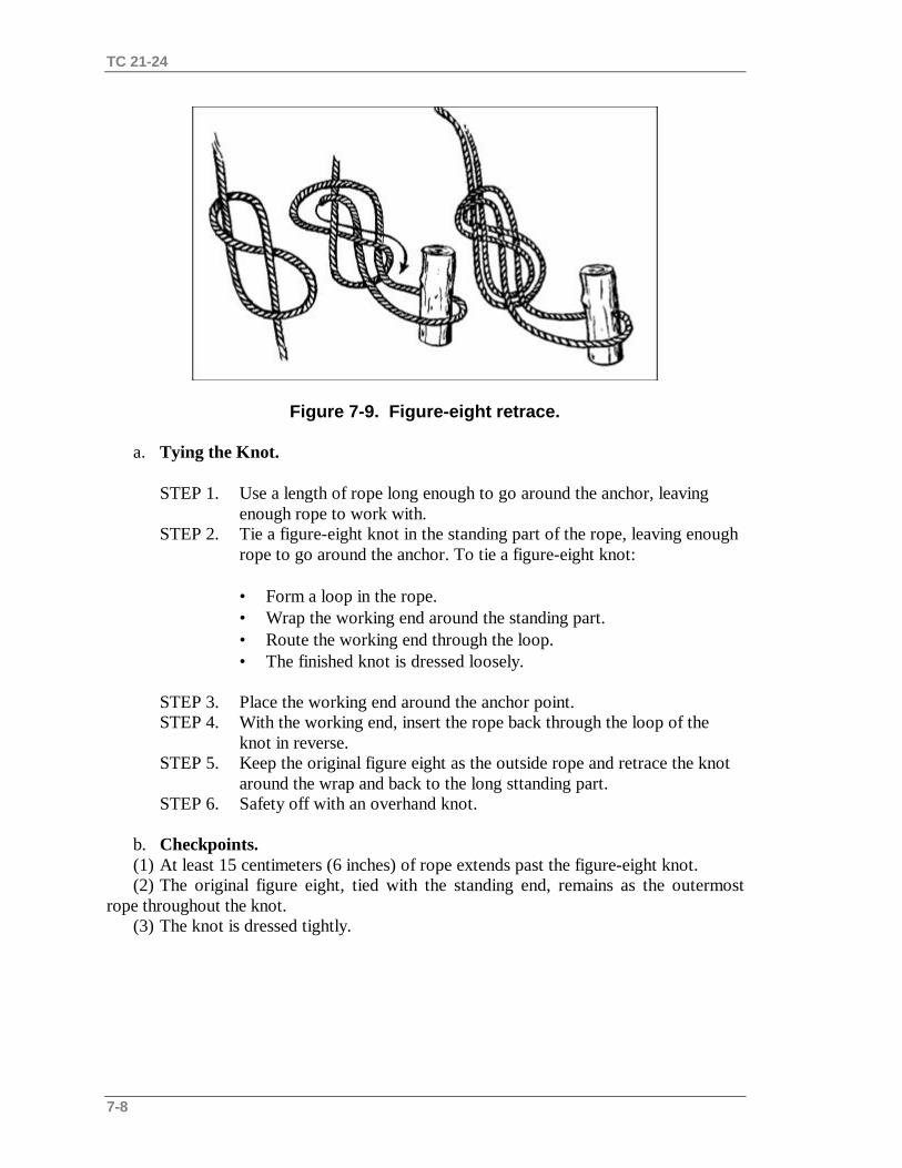
TC 21-24
7-8
Figure 7-9. Figure-eight retrace.
a. Tying the Knot.
STEP 1. Use a length of rope long enough to go around the anchor, leaving enough rope to work with.
STEP 2. Tie a figure-eight knot in the standing part of the rope, leaving enough rope to go around the anchor. To tie a figure-eight knot:
• Form a loop in the rope.• Wrap the working end around the standing part.• Route the working end through the loop.• The finished knot is dressed loosely.
STEP 3. Place the working end around the anchor point.STEP 4. With the working end, insert the rope back through the loop of the
knot in reverse.STEP 5. Keep the original figure eight as the outside rope and retrace the knot
around the wrap and back to the long sttanding part.STEP 6. Safety off with an overhand knot.
b. Checkpoints.(1) At least 15 centimeters (6 inches) of rope extends past the figure-eight knot.(2) The original figure eight, tied with the standing end, remains as the outermost
rope throughout the knot.(3) The knot is dressed tightly.
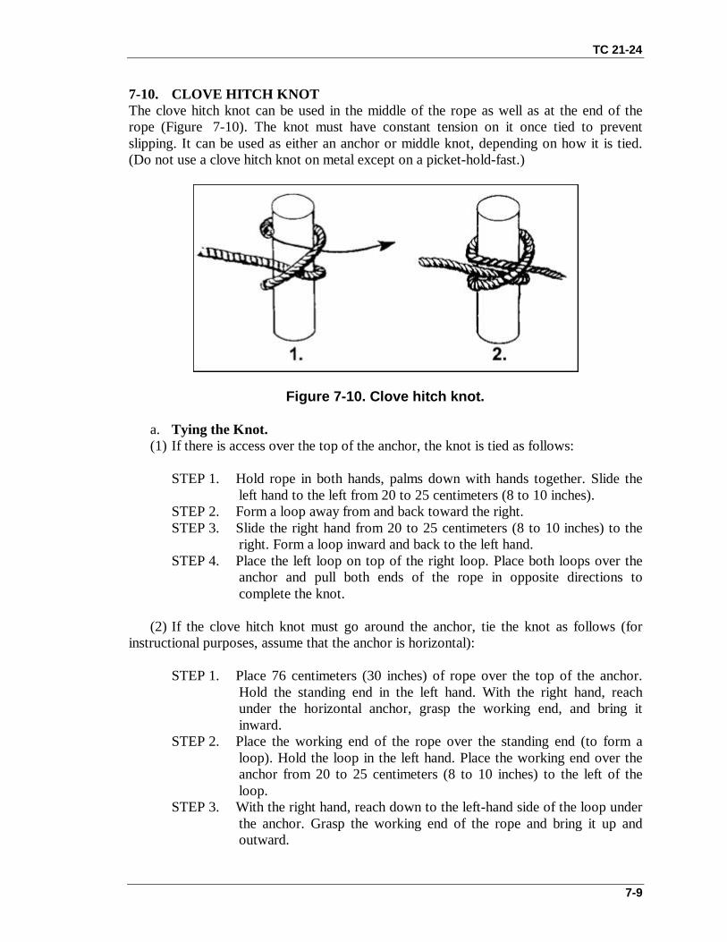
TC 21-24
7-9
7-10. CLOVE HITCH KNOTThe clove hitch knot can be used in the middle of the rope as well as at the end of therope (Figure 7-10). The knot must have constant tension on it once tied to preventslipping. It can be used as either an anchor or middle knot, depending on how it is tied.(Do not use a clove hitch knot on metal except on a picket-hold-fast.)
Figure 7-10. Clove hitch knot.
a. Tying the Knot.(1) If there is access over the top of the anchor, the knot is tied as follows:
STEP 1. Hold rope in both hands, palms down with hands together. Slide theleft hand to the left from 20 to 25 centimeters (8 to 10 inches).
STEP 2. Form a loop away from and back toward the right.STEP 3. Slide the right hand from 20 to 25 centimeters (8 to 10 inches) to the
right. Form a loop inward and back to the left hand.STEP 4. Place the left loop on top of the right loop. Place both loops over the
anchor and pull both ends of the rope in opposite directions tocomplete the knot.
(2) If the clove hitch knot must go around the anchor, tie the knot as follows (forinstructional purposes, assume that the anchor is horizontal):
STEP 1. Place 76 centimeters (30 inches) of rope over the top of the anchor.Hold the standing end in the left hand. With the right hand, reachunder the horizontal anchor, grasp the working end, and bring itinward.
STEP 2. Place the working end of the rope over the standing end (to form aloop). Hold the loop in the left hand. Place the working end over theanchor from 20 to 25 centimeters (8 to 10 inches) to the left of theloop.
STEP 3. With the right hand, reach down to the left-hand side of the loop underthe anchor. Grasp the working end of the rope and bring it up andoutward.

TC 21-24
7-10
STEP 4. Dress down the knot.
b. Checkpoints.(1) The knot has two round turns around the anchor with locking bar.(2) The locking bar is facing 90 degrees from the direction of pull.(3) The ends exit 180 degrees from each other.(4) The knot has more than a 15-centimeter (6-inch) pigtail remaining.
SECTION III. MIDDLE ROPE KNOTS
7-11. WIREMAN’S KNOTThe wireman’s knot forms a single, fixed loop in the middle of the rope (Figure 7-11).
Figure 7-11. Wireman’s knot.
a. Tying the Knot.
STEP 1. When tying this knot, face the anchor that the tie-off system will be tied to. Take up the slack from the anchor, and wrap two turns around the left hand (palm up) from left to right.
STEP 2. Take up a loop of 30 centimeters (12 inches) in the second round turn to create the fixed loop of the knot.
STEP 3. Name the wraps from the palm to the fingertips: heel, palm, and fingertip.
STEP 4. Grasp the palm wrap with the right thumb and forefinger, and place it over the heel wrap.
STEP 5. Grasp the heel wrap and place it over the fingertip wrap.STEP 6. Grasp the fingertip wrap and place it over the palm wrap.STEP 7. Grasp the palm wrap and pull up to form a fixed loop.STEP 8. Dress the knot down by pulling on the fixed loop and the two working
ends.STEP 9. Pull the working ends apart to finish the knot.

TC 21-24
7-11
b. Checkpoints.(1) The completed knot should have four separate bights locking down on themselves
with the fixed loop exiting from the top of the knot and laying toward the near sideanchor point.
(2) Both ends should exit opposite each other without any bends.
7-12. DIRECTIONAL FIGURE-EIGHT KNOTThe directional figure-eight knot forms a single, fixed loop in the middle of the rope thatlays back along the standing part of the rope (Figure 7-12).
Figure 7-12. Directional figure-eight knot.
a. Tying the Knot.
STEP 1. Face the far side anchor so that when the knot is tied, it lays inward.STEP 2. Lay the rope from the far side anchor over the left palm. Make one
wrap around the palm.STEP 3. With the wrap thus formed, tie a figure-eight knot around the standing
part that leads to the far side anchor.STEP 4. Dress the knot down with the tail and the bight together.
b. Checkpoints.(1) The loop should be large enough to accept a snaplink but no larger than a helmet-
size loop.(2) The tail and bight must be together.(3) The figure eight is tied tightly.(4) The bight in the knot faces back toward the near side.
7-13. BOWLINE-ON-A-BIGHT KNOTThe bowline-on-a-bight knot is used to form two fixed loops in the middle of a rope(Figure 7-13).

TC 21-24
7-12
Figure 7-13. Bowline-on-a-bight knot.
a. Tying the Knot.
STEP 1. Form a bight in the rope about twice as long as the finished loops will be.
STEP 2. Tie an overhand knot on a bight.STEP 3. Hold the overhand knot in the left hand so that the bight is running
down and outward.STEP 4. Grasp the bight with the right hand, fold it back over the overhand
knot so that the overhand knot goes through the bight.STEP 5. From the end (apex) of the bight, follow the bight back to where it
forms the cross in the overhand knot. Grasp the two ropes that run down and outward and pull up, forming two loops.
STEP 6. Pull the two ropes out of the overhand knot and dress the knot down.STEP 7. A final dress is required: grasp the ends of the two fixed loops and
pull, spreading them apart to ensure the loops do not slip.b. Checkpoints.
(1) There are two fixed loops that will not slip.(2) There are no twists in the knot.(3) A double loop is held in place by a bight.
7-14. FIGURE-EIGHT-ON-A-BIGHT KNOTThe figure-eight-on-a-bight knot is used to form two fixed loops in the middle of a rope . (Figure 7-14).
Figure 7-14. Figure-eight-on-a-bight knot.

TC 21-24
7-13
a. Tying the Knot.
STEP 1. Using the doubled rope, form a 46-centimeter (18-inch) bight in the left hand with the running end facing to the left.
STEP 2. Grasp the bight with the right hand and make a 360-degree turn aroundthe standing end in a counterclockwise direction.
STEP 3. With the working end, form another bight and place that bight through the loop just formed in the left hand.
STEP 4. Hold the bight with the left hand, and place the original bight (moving toward the left hand) over the knot.
STEP 5. Dress the knot down.
b. Checkpoints.(1) There is a double figure eight with two loops.(2) The knot will not slip.
7-15. OVERHAND LOOP KNOTThe overhand loop knot forms a single loop in the middle of a rope. It should not be usedin a transport tightening system (Figure 7-15).
Figure 7-15. Overhand loop knot
a. Tying the Knot.STEP 1. Form a bight in the rope about as long as the loop needed.STEP 2. With the bight, form an overhand knot using the bight as the working
end. Dress the knot tightly.
b. Checkpoints.(1) The loop is the desired size.(2) The ropes in the overhand knot are parallel and do not cross over each other.(3) The knot is tightly dressed.

TC 21-24
7-14
7-16. FIGURE-EIGHT LOOP KNOTThe figure-eight loop knot is a variation of the overhand loop and is easy to untie after ithas held weight (Figure 7-16).
Figure 7-16. Figure eight loop knot.
a. Tying the Knot.
STEP 1. Form a bight in the rope about as large as the diameter of the desiredloop.
STEP 2. With the bight as the working end, form a loop in rope (standing part).STEP 3. Wrap the working end around the standing part 360 degrees and feed
the working end through the loop. Dress the knot tightly.
b. Checkpoints.(1) The loop is the desired size.(2) The ropes in the loop are parallel and do not cross over each other.(3) The knot is tightly dressed.
SECTION IV. SPECIAL KNOTS
7-17. SINGLE BUTTERFLY KNOTThe single butterfly knot is used to form a single, fixed loop in the middle of the ropewithout using the ends (Figure 7-17). The butterfly can be used for the middle man in arope party as well as in a transport tightening system. The knot can be hard to untie whenheavy weight has been placed on it for extended periods.

TC 21-24
7-15
Figure 7-17. Single butterfly knot.
a. Tying the Knot.
STEP 1. Form a loop over the palm of the left hand.STEP 2. With the right hand, cross the two long-standing ends; reach under and
grasp the bottom of the loop formed in STEP 1.STEP 3. Route the bottom of the loop over the crossed standing ends and back
through the top of the loop.STEP 4. Hold the newly formed loop and dress the knot down, removing all of the
slack out of the knot.
b. Checkpoints.(1) The wings of the knot are dressed down tightly and as close together as possible.(2) The ropes between the wings are parallel with no crossovers.(3) The loop is no larger than a helmet but large enough to accept a snaplink.(4) All ropes in the knot are tightly dressed.
7-18. PRUSIK KNOTThe prusik knot is used to put a moveable rope on a fixed rope such as a prusik ascent ora tightening system. This knot can be tied as a middle, finger, or end knot.
a. Tying the Knot.(1) First method. The prusik knot is tied at the middle or end of a rope; there are
many ways to do this (Figure 7-18). The middle-of-the-rope prusik knot can be tied witha short rope to a long rope as follows:
STEP 1. Double the short rope, forming a bight, with the working ends even.Lay it over the long rope so that the closed end of the bight is 30centimeters (12 inches) below the long rope and the remaining part ofthe rope (working ends) is the closest to the rappeller; spread theworking end apart.

TC 21-24
7-16
STEP 2. Reach down through the 30-centimeter (12-inch) bight. Pull up both ofthe working ends and lay them over the long rope. Repeat this processmaking sure that the working ends pass in the middle of the first twowraps. Now there are four wraps and a locking bar working across themon the long rope.
STEP 3. Dress the wraps and locking bar down to ensure they are tight and not twisted. Tie an overhand knot with both ropes to prevent the knot fromslipping during periods of variable tension.
Figure 7-18. Middle-of-the-rope prusik knot.
(2) Second method. Another way of tying the prusik knot is the finger prusik(Figure 7-19).
STEP 1. Lay the rope across the thumb and index finger of the left hand.
STEP 2. Wrap the rope around the index finger twice (wrapping away from the rappeller). Wrap the rope around the thumb twice (wrapping towards the rappeller).
STEP 3. Place the thumb and index finger tip to tip. Push the wraps together so that the prusik is on the left thumb. Four wraps and a locking bar should be across them.
STEP 4. Pass the running end of the rope through the wraps of the prusik knot.
STEP 5. Dress the wraps and locking bar down to ensure they are tight and not twisted.

TC 21-24
7-17
Figure 7-19. Finger prusik knot.
(3) Third method. Another way of tying a prusik knot is the end-of-the-rope knot(Figure 7-20).
Figure 7-20. End-of-the-rope prusik knot.
STEP 1. Using an arm’s length of rope, place it over the long rope.STEP 2. Form a complete round turn in the rope.STEP 3. Cross over the standing part of the short rope with the working end of the
short rope.STEP 4. Lay the working end under the long rope.STEP 5. Form a complete round turn in the rope, working back toward the middle
of the knot.

TC 21-24
7-18
STEP 6. Four wraps and a locking bar should run across them on the long rope. Dress the wraps and locking bar down. Ensure they are tight, parallel, and not twisted.
STEP 7. Finish the knot with a bowline to ensure that the prusik knot will not slip out during periods of varying tension.
b. Checkpoints.(1) Four wraps with a locking bar.(2) The locking bar faces the rappeller.(3) The knot is tight and dressed down with no ropes twisted or crossed.(4) Other than a finger prusik, the knot should contain an overhand or bowline to
prevent slipping.
7-19. BACHMAN KNOTThe bachman knot provides a means of using a makeshift mechanized ascender (Figure7-21).
Figure 7-21. Bachman knot.
a. Tying the Knot.
STEP 1. Find the middle of a utility rope and insert it into a snaplink.STEP 2. Place the snaplink and utility rope next to a long climbing rope.STEP 3. With the two ropes parallel fromthe snaplink, make two or more wraps
wraps around the climbing rope and through the inside portion of the snaplink.
Note: The rope can be tied into an etrier (stirrup) and used as a prusik-friction principal ascender.
b. Checkpoints.(1) The bight of the climbing rope is at the top of the snaplink.(2) The two ropes run parallel without twisting or crossing.

TC 21-24
7-19
(3) Two or more wraps are made around the long climbing rope and through theinside portion of the snaplink.
7-20. BOWLINE-ON-A-COIL KNOTThe bowline-on-a-coil knot is an expedient tie-in used by rappellers in two- and three-man party climbs when a climbing harness is not available (Figure 7-22).
Figure 7-22. Bowline-on-a-coil knot.
Note: A safer tie in, when possible, is a swiss seat and figure eight around the shoulder, to avoid damaging the ribs if the climber falls.
a. Tying the Knot.STEP 1. To tie a bowline-on-a-coil knot, start the same as tying a bowline
around the waist. (The waist of the rappeller is the anchor point. The rappeller has about 40 centimeters [16 inches] of rope in the right hand. The standing end is coming from the remainder of the rope in hisleft hand.)
STEP 2. Draw slack from the standing end of the rope in the left hand, wrapping enough coils around the body to complete a minimum of four (but no more than six) coils.
STEP 3. With the rope in the left hand, make a loop inward with the standing end.

TC 21-24
7-20
STEP 4. Slide the loop up between the horizontal wraps and the body, ensuring that the loop does not come uncrossed.
STEP 5. Bring a bight up through the loop. Bring the working end of the rope in the right hand through the bight and back onto itself.
OR
Insert the short working end to the right through the loop (just passedthrough the wraps). Pass the working end around the long standing endand back on itself, forming a bight.
STEP 6. Dress the knot down.STEP 7. Safety off with an overhand knot against the knot formed on the top
single coil. From 10 to 15 centimeters (4 to 6 inches) of rope should beleft (standing part).
b. Checkpoints.(1) There are a minimum of four (maximum of six) parallel wraps; the top and
bottom ropes cross forward of the hips.(2) The loop must be underneath all wraps.(3) Other checkpoints are the same as the bowline.
7-21. THREE-LOOP BOWLINE KNOTThe three-loop bowline knot is used to form three fixed loops in the middle of a rope(Figure 7-23). It is used in a self-equalizing anchor system.
Figure 7-23. Three-loop bowline knot.
a. Tying the Knot.STEP 1. Form about a 60 centimeter (24-inch) bight in the rope, laying it
across the left hand, palm up, with the bight to the front.STEP 2. With the right hand, form a loop with both ropes. Hold it in the left
hand.STEP 3. With the right hand, bring the long bight through the loop(formed in
STEP 2) and around and around the two standing ends.

TC 21-24
7-21
STEP 4. Follow the bight around the standing ends and back down into theloop.
STEP 5. Hold all three loops in the left hand. With the right hand, grasp bothstanding ropes and pull while dressing up the bowline.
b. Checkpoints.(1) Checkpoints are the same as a regular bowline, except that it is tied with two
ropes.(2) An overhand knot must be tied if the third loop is not to be used as a secondary
anchor.
7-22. FIGURE-EIGHT SLIP KNOTThe figure-eight slip knot forms an adjustable bight in a rope (Figure 7-24).
Figure 7-24. Figure-eight slip knot.
a. Tying the Knot.
STEP 1. Form a 30-centimeter (12-inch) bight in the end of the rope.STEP 2. Hold the center of the bight in the right hand. Hold the two parallel
ropes from the bight in the left hand about 30 centimeters (12 inches)up the rope.
STEP 3. With the center of the bight in the right hand, twist two complete turnsclockwise.
STEP 4. Reach through the bight and grasp the long standing end of the rope.Pull another bight (from the long standing end) back through theoriginal bight.
STEP 5. Pull down on the short working end of the rope and dress the knotdown.
STEP 6. If the knot is to be used in a transport tightening system, take theworking end of the rope and form a half hitch around the loop of thefigure-eight knot.
b. Checkpoints.(1) The knot is in the shape of a figure eight.(2) The sliding portion of the rope is the long working end of the rope.

TC 21-24
7-22
Section V. SPECIAL-PURPOSE KNOTS
7-23. KLEIMHIEST KNOTThe kleimhiest knot provides a moveable, easily adjustable, high-tension knot capable ofholding extremely heavy loads while being pulled tight (Figure 7-25). This systemrequires a six-man pulling team when used in a transport tightening system.
Figure 7-25. Kleimhiest knot.
a. Tying the Knot.
STEP 1. Using a utility rope, offset the ends by 30 centimeters (12inches). Withthe ends offset, find the center of the rope and form a bight. Lay the bight over a horizontal rope near the far side anchor.
STEP 2. Wrap the tails of the utility rope around the horizontal rope back toward the near side anchor. Wrap at least four complete turns.
STEP 3. Pass the remaining tails of the utility rope through the bight (see STEP1).
STEP 4. Join the two ends of the tail with a joining knot (square knot with overhand safety knots).
STEP 5. Dress the knot down tightly so that all wraps are touching. Insert two snaplinks (opposing gates) into the large loop tied with the tails.
b. Checkpoints.(1) The bight is closest to the far side anchor.(2) All wraps are tight and touching.(3) The ends of the utility rope are properly secured with the adjoining knot.

TC 21-24
7-23
7-24. OVERHAND KNOTThe overhand knot (Figure 7-26) is used to make a knotted rope for a handline, to securethe ends of other knots, and to make stirrups in direct-aid climbing. This knot can also beused to temporarily whip the end of a rope. It is used with other knots.
Figure 7-26. Overhand knot.
a. Tying the Knot.
STEP 1. Make a loop in the rope.STEP 2. Pass the working end of the rope through the loop.STEP 3. Dress down the knot.
b. Checkpoints.(1) Running ends exit the loop in opposite directions.(2) The knot is dressed down tightly.
7-25. FROST KNOTThe frost knot is used when working with flat webbing (Figure 7-27). It holds better thana standard overhand knot or square knot.
Figure 7-27. Frost knot.

TC 21-24
7-24
a. Tying the Knot.
STEP 1. Lap one end (a bight) of webbing over the other (about 25 to 30 centimeters [10 to 12 inches]).
STEP 2. Tie an overhand knot with the newly formed triple-strand webbing; dress tightly.
b. Checkpoints.(1) The tails of the webbing run in opposite directions.(2) Three strands of webbing are formed into a tight overhand knot.(3) A bight and tail exit the top of the overhand knot.
7-26. GIRTH HITCH KNOTThe girth hitch knot is used in tying a runner to a partly driven piton (Figure 7-28).
Figure 7-28. Girth hitch knot.
a. Tying the Knot.
STEP 1. Bring the standing ends back through the bight of a length of rope or webbing.
STEP 2. Dress the knot tightly.
b. Checkpoints.(1) Two wraps exist with a locking bar running across the wraps.(2) The knot is dressed tightly.

A-1
APPENDIX A
RISK ASSESSMENT
This appendix explains risk assessment for rappel operations. A riskassessement matrix is shown in Table A-1.
A-1. EFFECTa. Catastrophic. Death or permanent total disability, system loss, major property
damage.b. Critical. Permanent partial disability, temporary total disability in excess of three
months, major system damage, significant property damage.c. Moderate.Minor injury, lost workday accident, compensable injury or illness, minor
system damage, minor property damage.d. Negligible. First aid or minor supportive medical treatment, minor system impairment.
A-2. PROBABILITYa. Frequent.
(1) Individual soldier or item— Occurs often in career or equipment service life.(2) All soldiers exposed or item inventory— Continuously experienced.b. Likely.
(1) Individual soldier or item— Occurs several times in career or equipment service life.(2) All soldier exposed or item inventory— Occurs frequently.c. Occasional.
(1) Individual soldier or item— Occurs sometime in career or equipment service life.(2) All soldiers exposed or item inventory— Occurs sporadically, or several times ininventory service life.d. Seldom.
(1) Individual soldier or item— Possible to occur in career or equipment service life.(2) All soldiers exposed or item inventory— Remote chance of occurrence; expected tooccur sometime in inventory service life.e. Unlikely.(1) Individual soldier or item— Can assume will not occur in career or equipment service
life.(2) All soldiers exposed or item inventory— Possible, but improbable; occurs only very
rarely.
A-3. RISK LEVELSa. Extremely High. Loss of ability to accomplish mission.b. High. Significantly degrades mission capabilities in terms of required mission
standards.c. Medium. Degrades mission capabilities in terms of required mission standards.d. Low. Little or no impact on mission accomplishment.

TC 21-24
A-2
HAZARD PROBABILITY
Frequent
Likely
Occasional
Seldom
UnlikelyRISK ASSESSMENT
A B C D E
Catastrophic I Extremely High
Critical II High
Moderate III Medium
EFFECT
Negligible IV Low
Table A-1. Risk assessment matrix.

B-1
APPENDIX B
BASIC EQUIPMENT FOR RAPPEL OPERATIONS
The equipment listed in this appendix is the standard basic items required toconduct ground and air rappelling operations.
B-1. GROUND OPERATIONSFor ground operations, the following equipment is needed:
a. Nylon rope, 120 feet (NSN 4020-00-931-8793).b. Snaplinks (NSN 8465-00-360-0228).c. Gloves (NSN 8415-00-268-7868).d. Rope coiling log or standard deployment bag.e. Rappel seat.f. Rappel rings (used as expedient anchor points).
B-2. AIR OPERATIONSFor air operations, the following equipment is needed:
a. All items in paragraph B-1.b. Donut ring (UH-1H operations only) (locally produced TSC item).c. Safety floating ring.d. Two 6-foot safety ropes (with snaplinks).e. Eight 120-foot nylon ropes.f. Monkey harness for static rappel master.g. Sixteen snaplinks (UH-60 operations).h. Twenty-two snaplinks (UH-1H operations).i. FM communications.j. Aircraft communications headset.