Traffic Signal Phasing, Course #310 Presented by · traffic signal operations course – traffic...
24
TRAFFIC SIGNAL OPERATIONS COURSE – TRAFFIC SIGNAL PHASING Copyright © Jeffrey W. Buckholz, PhD, PE, PTOE Page 1 of 24 Traffic Signal Phasing, Course #310 Presented by: PDH Enterprises, LLC PO Box 942 Morrisville, NC 27560 (919)208-5296 www.PDHSite.com Course Author: Jeffrey W. Buckholz, PhD, PE, PTOE TRAFFIC SIGNAL PHASING This Traffic Signal Operations course presents information regarding phasing sequences used for traffic signal control. The material is intended to provide a practical overview of traffic signal phasing and its proper application. Since fully actuated controller operation demonstrates the most sophisticated features and capabilities with respect to signal phasing, the explanation of phasing concepts centers on this mode of controller operation. However, many of the concepts are similar for pre-timed or semi- actuated controller operation. This is not an introductory course and a basic knowledge of traffic signal operation is assumed. Since traffic engineers and traffic technicians use the word "phasing" a little differently, confusion can occur. Technicians typically have in mind the individual vehicle movements (or NEMA phases) when they speak of phasing, whereas traffic engineers are typically referring to a specific combination of phases, or what one might call a phase set. For example, when opposing main street left turns go green together, the engineer would say that the lead left turn phase (or more precisely, the lead left turn phase set) has started, whereas the technician would say that phases 1 and 5 have begun concurrent operation.
-
Upload
truongtruc -
Category
Documents
-
view
223 -
download
1
Transcript of Traffic Signal Phasing, Course #310 Presented by · traffic signal operations course – traffic...
TRAFFIC SIGNAL OPERATIONS COURSE – TRAFFIC SIGNAL PHASING
Copyright © Jeffrey W. Buckholz, PhD, PE, PTOE Page 1 of 24
Traffic Signal Phasing, Course #310 Presented by:
PDH Enterprises, LLC PO Box 942
Morrisville, NC 27560 (919)208-5296
www.PDHSite.com
Course Author: Jeffrey W. Buckholz, PhD, PE, PTOE
TRAFFIC SIGNAL PHASING This Traffic Signal Operations course presents information regarding phasing sequences used for traffic signal control. The material is intended to provide a practical overview of traffic signal phasing and its proper application. Since fully actuated controller operation demonstrates the most sophisticated features and capabilities with respect to signal phasing, the explanation of phasing concepts centers on this mode of controller operation. However, many of the concepts are similar for pre-timed or semi-actuated controller operation. This is not an introductory course and a basic knowledge of traffic signal operation is assumed. Since traffic engineers and traffic technicians use the word "phasing" a little differently, confusion can occur. Technicians typically have in mind the individual vehicle movements (or NEMA phases) when they speak of phasing, whereas traffic engineers are typically referring to a specific combination of phases, or what one might call a phase set. For example, when opposing main street left turns go green together, the engineer would say that the lead left turn phase (or more precisely, the lead left turn phase set) has started, whereas the technician would say that phases 1 and 5 have begun concurrent operation.
TRAFFIC SIGNAL OPERATIONS COURSE – TRAFFIC SIGNAL PHASING
Copyright © Jeffrey W. Buckholz, PhD, PE, PTOE Page 2 of 24
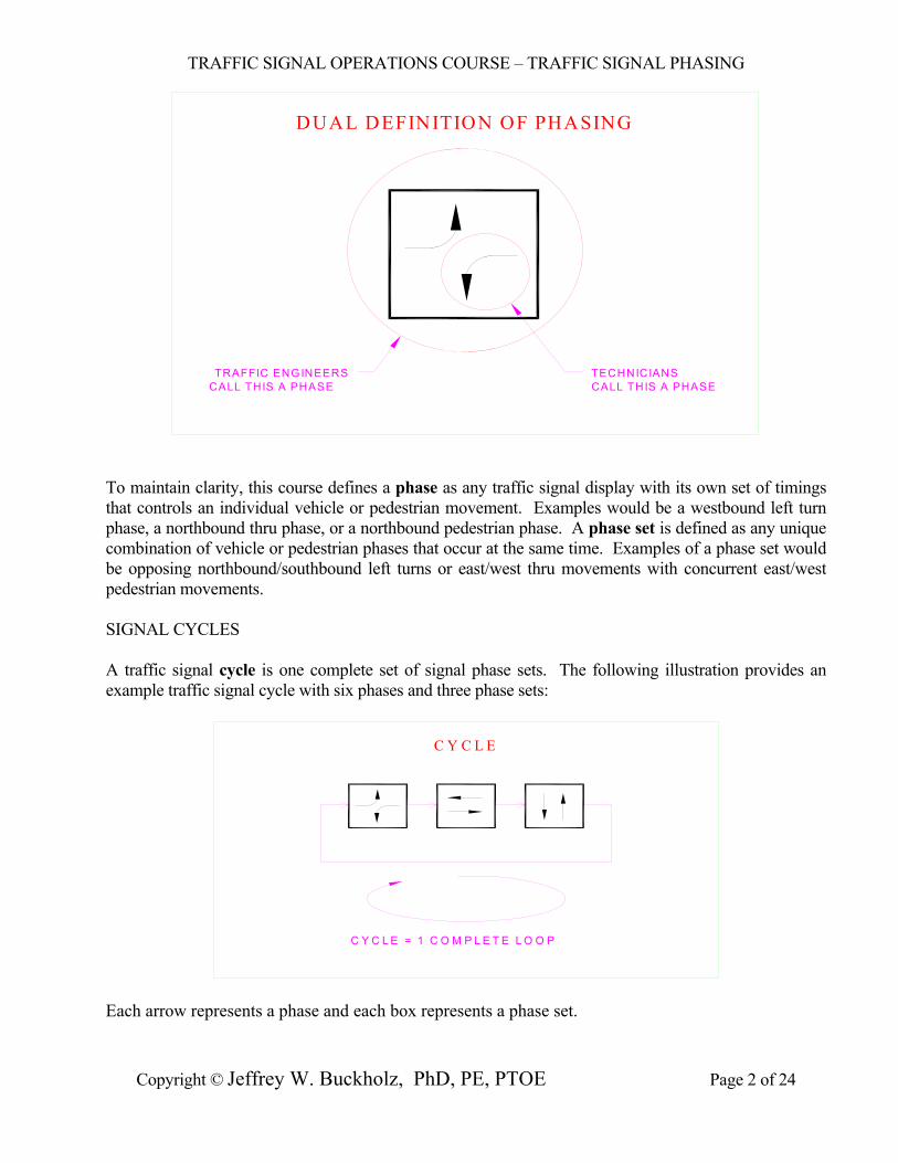
DUAL DEFINITION OF PHASING
TRAFFIC ENGINEERSCALL THIS A PHASE CALL THIS A PHASE
TECHNICIANS
To maintain clarity, this course defines a phase as any traffic signal display with its own set of timings that controls an individual vehicle or pedestrian movement. Examples would be a westbound left turn phase, a northbound thru phase, or a northbound pedestrian phase. A phase set is defined as any unique combination of vehicle or pedestrian phases that occur at the same time. Examples of a phase set would be opposing northbound/southbound left turns or east/west thru movements with concurrent east/west pedestrian movements. SIGNAL CYCLES A traffic signal cycle is one complete set of signal phase sets. The following illustration provides an example traffic signal cycle with six phases and three phase sets:
C Y C L E
C Y C L E = 1 C O M P L E T E L O O P
Each arrow represents a phase and each box represents a phase set.
TRAFFIC SIGNAL OPERATIONS COURSE – TRAFFIC SIGNAL PHASING
Copyright © Jeffrey W. Buckholz, PhD, PE, PTOE Page 3 of 24
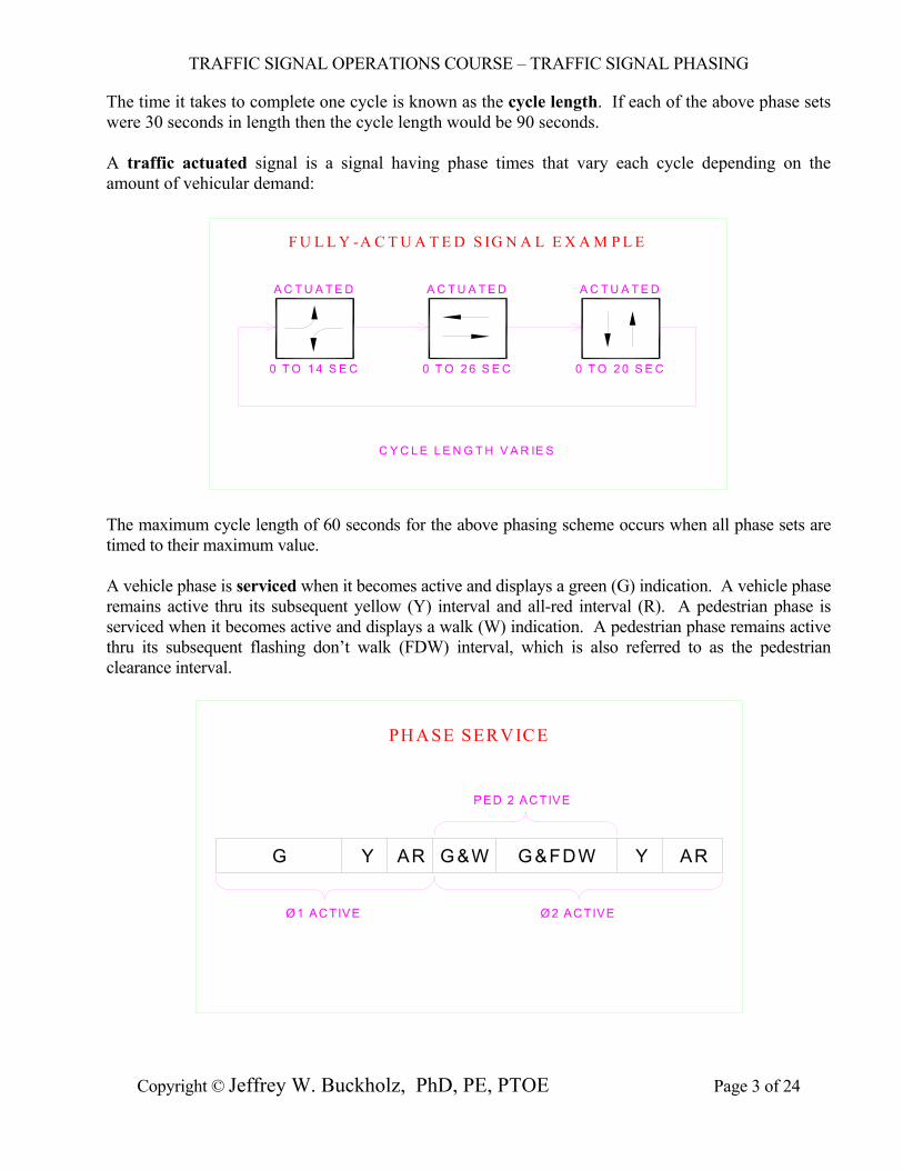
The time it takes to complete one cycle is known as the cycle length. If each of the above phase sets were 30 seconds in length then the cycle length would be 90 seconds. A traffic actuated signal is a signal having phase times that vary each cycle depending on the amount of vehicular demand:
F U L L Y -A C T U A T E D S IG N A L E X A M P L E
0 T O 1 4 S E C 0 T O 2 6 S E C 0 T O 2 0 S E C
A C T U A T E D A C T U A T E D A C T U A T E D
C Y C L E L E N G T H V A R IE S
The maximum cycle length of 60 seconds for the above phasing scheme occurs when all phase sets are timed to their maximum value. A vehicle phase is serviced when it becomes active and displays a green (G) indication. A vehicle phase remains active thru its subsequent yellow (Y) interval and all-red interval (R). A pedestrian phase is serviced when it becomes active and displays a walk (W) indication. A pedestrian phase remains active thru its subsequent flashing don’t walk (FDW) interval, which is also referred to as the pedestrian clearance interval.
PH A SE SERV ICE
G Y AR G &W G&FDW Y AR
Ø 1 ACTIVE Ø 2 ACTIVE
PED 2 ACTIVE
TRAFFIC SIGNAL OPERATIONS COURSE – TRAFFIC SIGNAL PHASING
Copyright © Jeffrey W. Buckholz, PhD, PE, PTOE Page 4 of 24
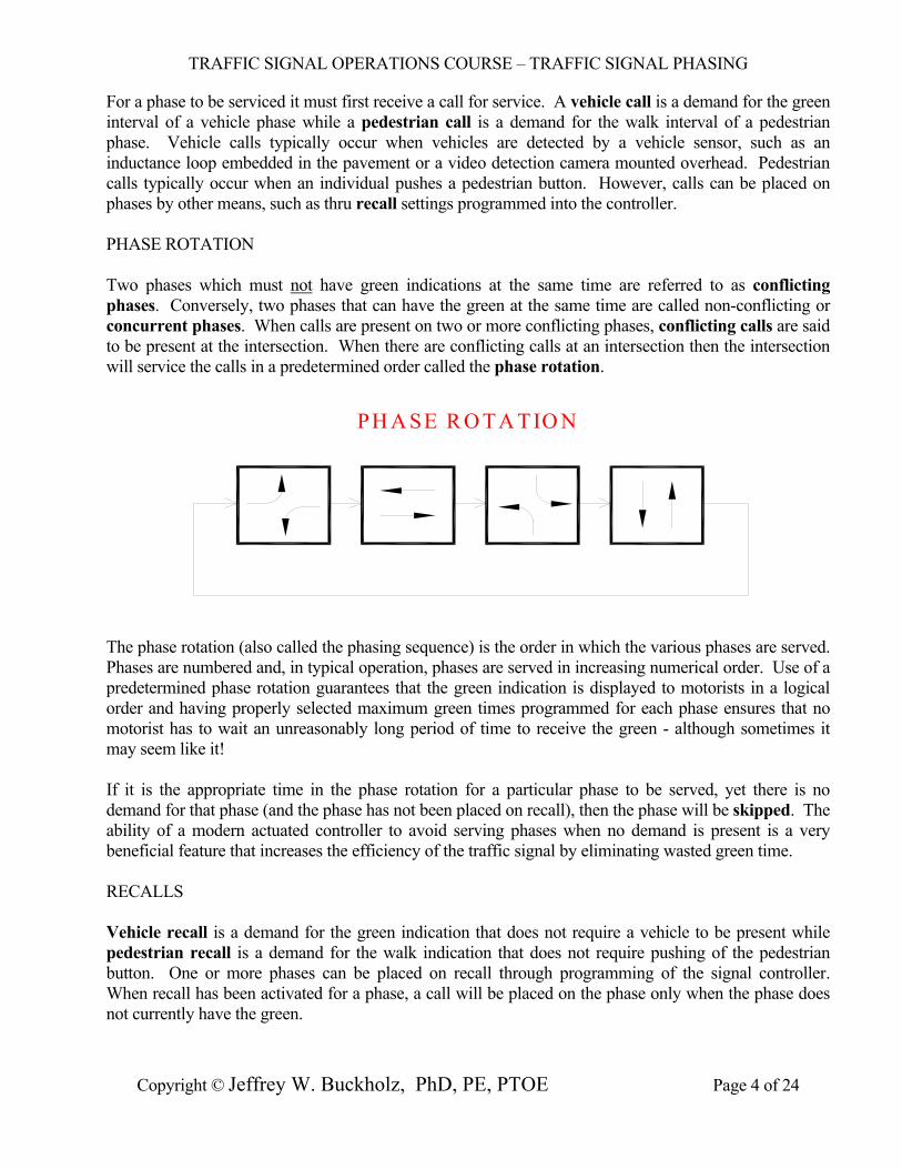
For a phase to be serviced it must first receive a call for service. A vehicle call is a demand for the green interval of a vehicle phase while a pedestrian call is a demand for the walk interval of a pedestrian phase. Vehicle calls typically occur when vehicles are detected by a vehicle sensor, such as an inductance loop embedded in the pavement or a video detection camera mounted overhead. Pedestrian calls typically occur when an individual pushes a pedestrian button. However, calls can be placed on phases by other means, such as thru recall settings programmed into the controller. PHASE ROTATION Two phases which must not have green indications at the same time are referred to as conflicting phases. Conversely, two phases that can have the green at the same time are called non-conflicting or concurrent phases. When calls are present on two or more conflicting phases, conflicting calls are said to be present at the intersection. When there are conflicting calls at an intersection then the intersection will service the calls in a predetermined order called the phase rotation.
PH A SE R O TA TIO N
The phase rotation (also called the phasing sequence) is the order in which the various phases are served. Phases are numbered and, in typical operation, phases are served in increasing numerical order. Use of a predetermined phase rotation guarantees that the green indication is displayed to motorists in a logical order and having properly selected maximum green times programmed for each phase ensures that no motorist has to wait an unreasonably long period of time to receive the green - although sometimes it may seem like it! If it is the appropriate time in the phase rotation for a particular phase to be served, yet there is no demand for that phase (and the phase has not been placed on recall), then the phase will be skipped. The ability of a modern actuated controller to avoid serving phases when no demand is present is a very beneficial feature that increases the efficiency of the traffic signal by eliminating wasted green time. RECALLS Vehicle recall is a demand for the green indication that does not require a vehicle to be present while pedestrian recall is a demand for the walk indication that does not require pushing of the pedestrian button. One or more phases can be placed on recall through programming of the signal controller. When recall has been activated for a phase, a call will be placed on the phase only when the phase does not currently have the green.

TRAFFIC SIGNAL OPERATIONS COURSE – TRAFFIC SIGNAL PHASING
Copyright © Jeffrey W. Buckholz, PhD, PE, PTOE Page 5 of 24
The following three types of vehicle recall are typically available: o Minimum Recall o Maximum Recall o Soft Recall The following timing chart shows that minimum recall is active for NEMA phases 2 and 6 at this signalized intersection:
RECALL
MAX Recall
MIN Recall
PED Recall
Soft Recall
Phase Omit
Flashing Walk
CNA 1
CNA 2
Ped Omit
Non-Locking
DESCRIPTIONPHASE
1 2 3 4 5 6 87
X
X
X X
X
X
X
X
X
X
Minimum recall places a call on a phase and then keeps the phase green for at least as long as the initial (or minimum) setting programmed in the signal controller. The phase's green interval may be longer than the initial if actual vehicles continue to activate the vehicle detector and extend the green, but it will never be less than the initial setting. Maximum recall places a call on a phase and then keeps the phase green for a time equal to the maximum setting programmed in the signal controller. Unless there is no other demand at the intersection, the green interval for the phase on maximum recall will exactly equal the maximum setting, it will not be any less or any greater. If there is no other conflicting demand at the intersection once the maximum interval has fully timed, the green time will continue to be displayed to the recall phases until such demand occurs. In this case, the green time experienced by the recall phases will be longer than their maximum green setting. The recall phases are said to rest in green during the period when the actual green time exceeds the maximum green time. Soft recall is almost the same as minimum recall, with one important difference: soft recall will discontinue its call for the green if there are conflicting calls at the intersection generated by actual vehicle demand. The end result is that phases set to soft recall can be skipped if there is no actual
TRAFFIC SIGNAL OPERATIONS COURSE – TRAFFIC SIGNAL PHASING
Copyright © Jeffrey W. Buckholz, PhD, PE, PTOE Page 6 of 24
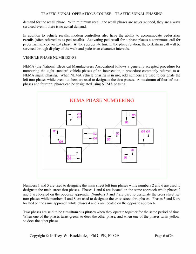
demand for the recall phase. With minimum recall, the recall phases are never skipped, they are always serviced even if there is no actual demand. In addition to vehicle recalls, modern controllers also have the ability to accommodate pedestrian recalls (often referred to as ped recalls). Activating ped recall for a phase places a continuous call for pedestrian service on that phase. At the appropriate time in the phase rotation, the pedestrian call will be serviced through display of the walk and pedestrian clearance intervals. VEHICLE PHASE NUMBERING NEMA (the National Electrical Manufacturers Association) follows a generally accepted procedure for numbering the eight standard vehicle phases of an intersection, a procedure commonly referred to as NEMA signal phasing. When NEMA vehicle phasing is in use, odd numbers are used to designate the left turn phases while even numbers are used to designate the thru phases. A maximum of four left turn phases and four thru phases can be designated using NEMA phasing:
NEMA PHASE NUMBERING
Ø1
Ø5
Ø5Ø2
Ø6Ø1
Ø2
Ø6 Ø7
Ø3
Ø8
Ø3
Ø4
Ø7
Ø8 Ø4
Numbers 1 and 5 are used to designate the main street left turn phases while numbers 2 and 6 are used to designate the main street thru phases. Phases 1 and 6 are located on the same approach while phases 2 and 5 are located on the opposite approach. Numbers 3 and 7 are used to designate the cross street left turn phases while numbers 4 and 8 are used to designate the cross street thru phases. Phases 3 and 8 are located on the same approach while phases 4 and 7 are located on the opposite approach. Two phases are said to be simultaneous phases when they operate together for the same period of time. When one of the phases turns green, so does the other phase, and when one of the phases turns yellow, so does the other phase.
TRAFFIC SIGNAL OPERATIONS COURSE – TRAFFIC SIGNAL PHASING
Copyright © Jeffrey W. Buckholz, PhD, PE, PTOE Page 7 of 24
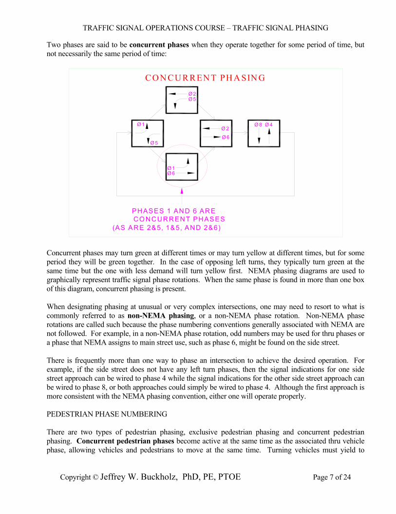
Two phases are said to be concurrent phases when they operate together for some period of time, but not necessarily the same period of time:
C O N CU R R EN T PH A SIN G
Ø 1
Ø 5
Ø 5Ø 2
Ø 6Ø 1
Ø 2
Ø 6
Ø 8 Ø 4
PHASES 1 AND 6 ARECO NCURRENT PHASES
(AS ARE 2&5, 1&5, AND 2&6)
Concurrent phases may turn green at different times or may turn yellow at different times, but for some period they will be green together. In the case of opposing left turns, they typically turn green at the same time but the one with less demand will turn yellow first. NEMA phasing diagrams are used to graphically represent traffic signal phase rotations. When the same phase is found in more than one box of this diagram, concurrent phasing is present. When designating phasing at unusual or very complex intersections, one may need to resort to what is commonly referred to as non-NEMA phasing, or a non-NEMA phase rotation. Non-NEMA phase rotations are called such because the phase numbering conventions generally associated with NEMA are not followed. For example, in a non-NEMA phase rotation, odd numbers may be used for thru phases or a phase that NEMA assigns to main street use, such as phase 6, might be found on the side street. There is frequently more than one way to phase an intersection to achieve the desired operation. For example, if the side street does not have any left turn phases, then the signal indications for one side street approach can be wired to phase 4 while the signal indications for the other side street approach can be wired to phase 8, or both approaches could simply be wired to phase 4. Although the first approach is more consistent with the NEMA phasing convention, either one will operate properly. PEDESTRIAN PHASE NUMBERING There are two types of pedestrian phasing, exclusive pedestrian phasing and concurrent pedestrian phasing. Concurrent pedestrian phases become active at the same time as the associated thru vehicle phase, allowing vehicles and pedestrians to move at the same time. Turning vehicles must yield to
TRAFFIC SIGNAL OPERATIONS COURSE – TRAFFIC SIGNAL PHASING
Copyright © Jeffrey W. Buckholz, PhD, PE, PTOE Page 8 of 24
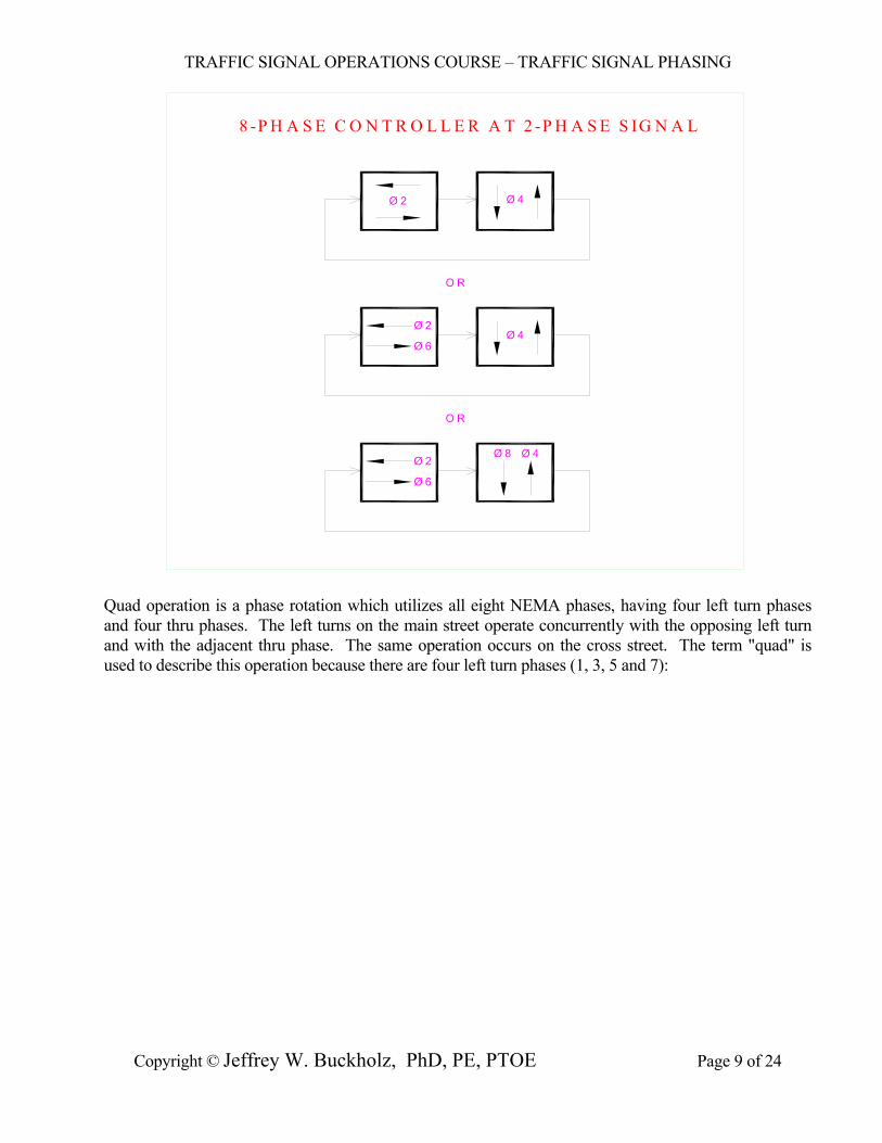
pedestrians that have legally entered the crosswalk. When exclusive pedestrian phases are active, no vehicles are allowed to move during the pedestrian crossing interval. Although it provides maximum protection for pedestrians, exclusive pedestrian operation can result in considerable vehicular delay at an intersection and should be used only where absolutely needed. NEMA also has a generally accepted procedure for numbering the four standard pedestrian phases of an intersection. When NEMA pedestrian phase numbering is in use, each concurrent pedestrian phase has the same number as the vehicle thru phase to which it is associated. The vehicle movements associated with this thru phase are typically adjacent to, and run parallel with, the crosswalk for the pedestrian phase. Since concurrent pedestrian phases have the same numbers as thru phases, they are always even numbers (2, 4, 6, or 8) if NEMA phasing conventions are being followed. PHASING OPTIONS AND EXAMPLES Traffic signal controllers typically come with either two-phase, four-phase, or eight-phase capabilities. The older two-phase controllers are the most basic and can control only the simplest of intersections - intersections without left turn phases. Four-phase controllers can handle more complicated intersections, such as T-intersections with main street left turn phasing and freeway off ramps. Modern eight-phase controllers can handle virtually any type of signalized intersection. Most controller manufacturers now make available 12 or 16 phase units which can handle extremely complex phasing requirements such as those sometimes found at five-leg intersections and intersections with frontage roads. As the number of signal phases increases, the size, complexity, and cost of the controller assembly needed to accommodate these phases increases correspondingly. A two-phase signal has the simplest of all phasing arrangements, having no left turn phases at all. If a two-phase controller is used at a simple two-phase signal then both approaches of the main street might be wired to phase 1 while the side street is wired to phase 2, or vice versa. If an eight-phase controller is used at a two-phase signal then the main street might be wired to phase 2 while the side street is wired to phase 4. Alternatively, the main street phases might be wired to 2 and 6 while the side street phases are wired to 4 and 8 or to 4 only. All of these alternatives would be generally consistent with NEMA phasing conventions. A large variety of phase numbering options exist when an eight-phase controller is used at a two-phase signal:
TRAFFIC SIGNAL OPERATIONS COURSE – TRAFFIC SIGNAL PHASING
Copyright © Jeffrey W. Buckholz, PhD, PE, PTOE Page 9 of 24
8 -P H A S E C O N T R O L L E R A T 2 -P H A S E S IG N A L
Ø 2Ø 4
Ø 8
Ø 2 Ø 4
Ø 6
Ø 6
Ø 2Ø 4
O R
O R
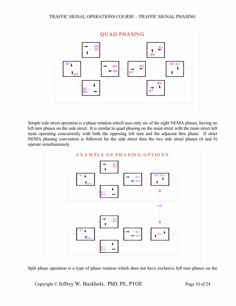
Quad operation is a phase rotation which utilizes all eight NEMA phases, having four left turn phases and four thru phases. The left turns on the main street operate concurrently with the opposing left turn and with the adjacent thru phase. The same operation occurs on the cross street. The term "quad" is used to describe this operation because there are four left turn phases (1, 3, 5 and 7):
TRAFFIC SIGNAL OPERATIONS COURSE – TRAFFIC SIGNAL PHASING
Copyright © Jeffrey W. Buckholz, PhD, PE, PTOE Page 10 of 24
QUAD PHASING
Ø1
Ø5
Ø5Ø2
Ø6Ø1
Ø2
Ø6 Ø7
Ø3
Ø8
Ø3
Ø4
Ø7
Ø8 Ø4
Simple side street operation is a phase rotation which uses only six of the eight NEMA phases, having no left turn phases on the side street. It is similar to quad phasing on the main street with the main street left turns operating concurrently with both the opposing left turn and the adjacent thru phase. If strict NEMA phasing convention is followed for the side street then the two side street phases (4 and 8) operate simultaneously.
E X A M P L E O F P H A S I N G O P T I O N S
Ø 1
Ø 5
Ø 5Ø 2
Ø 6Ø 1
Ø 2
Ø 6
Ø 8 Ø 4
O R
Ø 6
Ø 1
Ø 1
Ø 5Ø 6
Ø 2
Ø 5Ø 2
Ø 4
Split phase operation is a type of phase rotation which does not have exclusive left turn phases on the
TRAFFIC SIGNAL OPERATIONS COURSE – TRAFFIC SIGNAL PHASING
Copyright © Jeffrey W. Buckholz, PhD, PE, PTOE Page 11 of 24
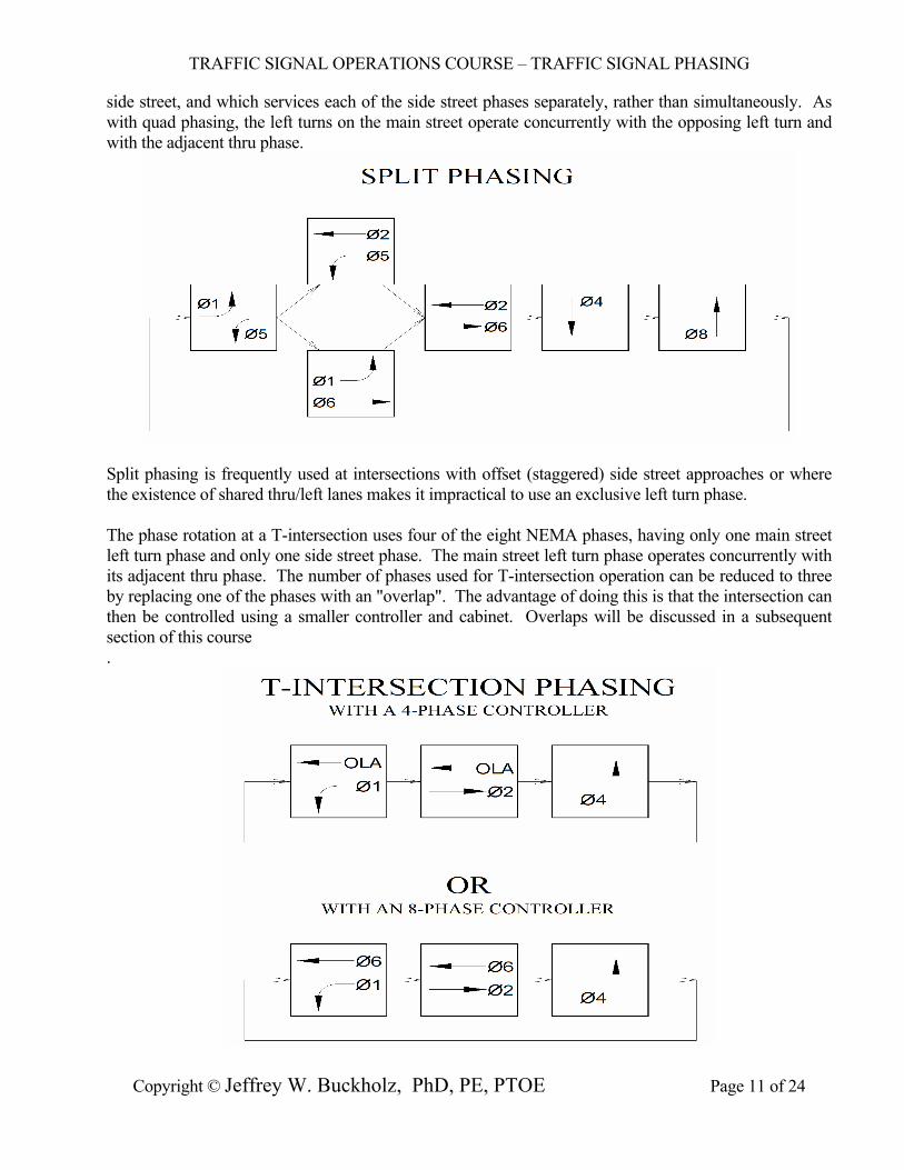
side street, and which services each of the side street phases separately, rather than simultaneously. As with quad phasing, the left turns on the main street operate concurrently with the opposing left turn and with the adjacent thru phase.
Split phasing is frequently used at intersections with offset (staggered) side street approaches or where the existence of shared thru/left lanes makes it impractical to use an exclusive left turn phase. The phase rotation at a T-intersection uses four of the eight NEMA phases, having only one main street left turn phase and only one side street phase. The main street left turn phase operates concurrently with its adjacent thru phase. The number of phases used for T-intersection operation can be reduced to three by replacing one of the phases with an "overlap". The advantage of doing this is that the intersection can then be controlled using a smaller controller and cabinet. Overlaps will be discussed in a subsequent section of this course .
TRAFFIC SIGNAL OPERATIONS COURSE – TRAFFIC SIGNAL PHASING
Copyright © Jeffrey W. Buckholz, PhD, PE, PTOE Page 12 of 24
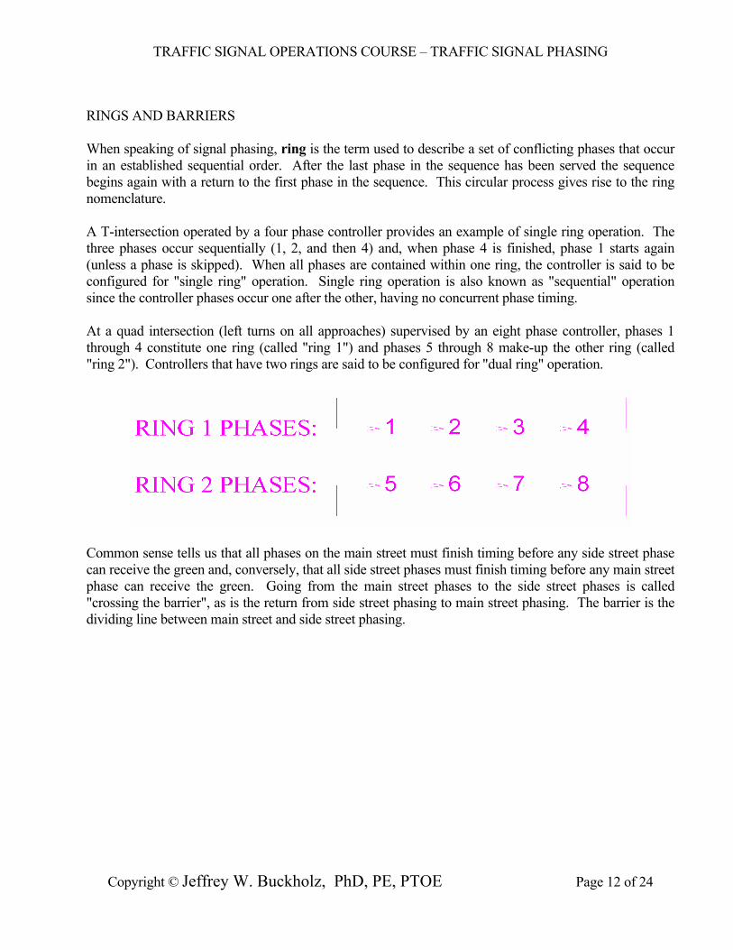
RINGS AND BARRIERS When speaking of signal phasing, ring is the term used to describe a set of conflicting phases that occur in an established sequential order. After the last phase in the sequence has been served the sequence begins again with a return to the first phase in the sequence. This circular process gives rise to the ring nomenclature. A T-intersection operated by a four phase controller provides an example of single ring operation. The three phases occur sequentially (1, 2, and then 4) and, when phase 4 is finished, phase 1 starts again (unless a phase is skipped). When all phases are contained within one ring, the controller is said to be configured for "single ring" operation. Single ring operation is also known as "sequential" operation since the controller phases occur one after the other, having no concurrent phase timing. At a quad intersection (left turns on all approaches) supervised by an eight phase controller, phases 1 through 4 constitute one ring (called "ring 1") and phases 5 through 8 make-up the other ring (called "ring 2"). Controllers that have two rings are said to be configured for "dual ring" operation.
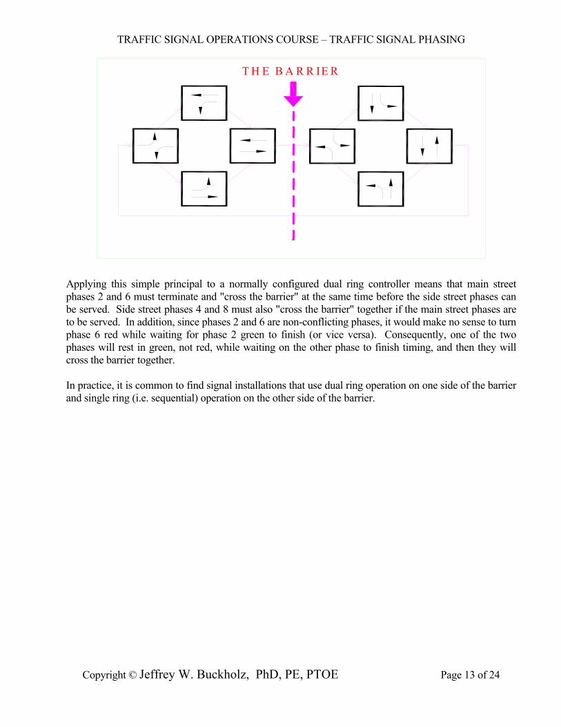
Common sense tells us that all phases on the main street must finish timing before any side street phase can receive the green and, conversely, that all side street phases must finish timing before any main street phase can receive the green. Going from the main street phases to the side street phases is called "crossing the barrier", as is the return from side street phasing to main street phasing. The barrier is the dividing line between main street and side street phasing.
TRAFFIC SIGNAL OPERATIONS COURSE – TRAFFIC SIGNAL PHASING
Copyright © Jeffrey W. Buckholz, PhD, PE, PTOE Page 13 of 24
T H E B A R R IE R
Applying this simple principal to a normally configured dual ring controller means that main street phases 2 and 6 must terminate and "cross the barrier" at the same time before the side street phases can be served. Side street phases 4 and 8 must also "cross the barrier" together if the main street phases are to be served. In addition, since phases 2 and 6 are non-conflicting phases, it would make no sense to turn phase 6 red while waiting for phase 2 green to finish (or vice versa). Consequently, one of the two phases will rest in green, not red, while waiting on the other phase to finish timing, and then they will cross the barrier together. In practice, it is common to find signal installations that use dual ring operation on one side of the barrier and single ring (i.e. sequential) operation on the other side of the barrier.
TRAFFIC SIGNAL OPERATIONS COURSE – TRAFFIC SIGNAL PHASING
Copyright © Jeffrey W. Buckholz, PhD, PE, PTOE Page 14 of 24
M IXED OPERATION
Ø1
Ø5
Ø5Ø2
Ø6Ø1
Ø2
Ø6Ø3
Ø4
CONCURRENT PHASING(DUAL RING) (SINGLE RING)
SEQUENTIAL PHASING
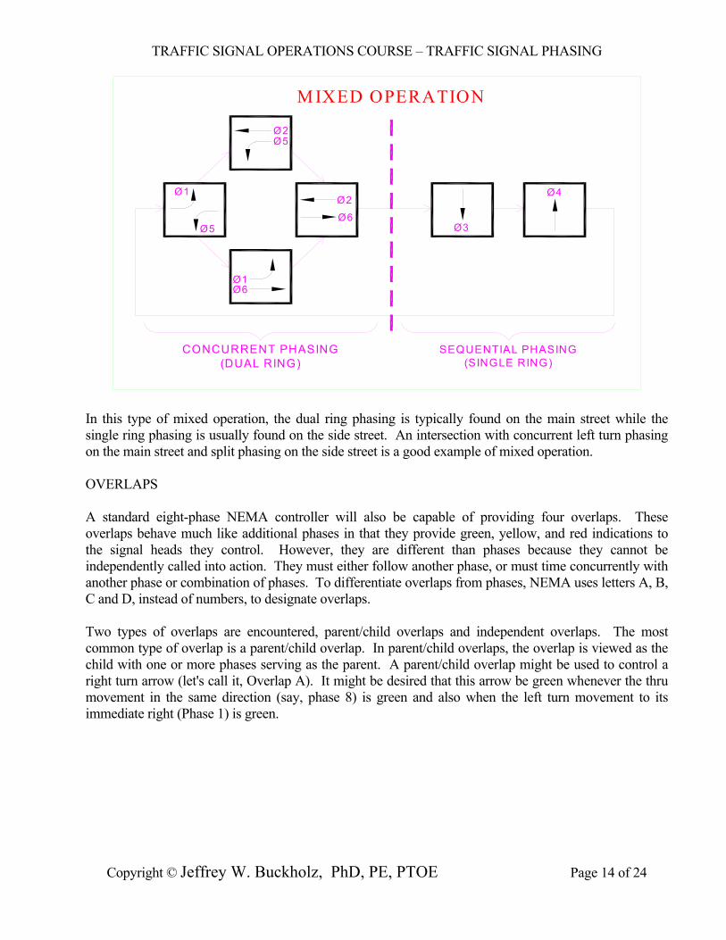
In this type of mixed operation, the dual ring phasing is typically found on the main street while the single ring phasing is usually found on the side street. An intersection with concurrent left turn phasing on the main street and split phasing on the side street is a good example of mixed operation. OVERLAPS A standard eight-phase NEMA controller will also be capable of providing four overlaps. These overlaps behave much like additional phases in that they provide green, yellow, and red indications to the signal heads they control. However, they are different than phases because they cannot be independently called into action. They must either follow another phase, or must time concurrently with another phase or combination of phases. To differentiate overlaps from phases, NEMA uses letters A, B, C and D, instead of numbers, to designate overlaps. Two types of overlaps are encountered, parent/child overlaps and independent overlaps. The most common type of overlap is a parent/child overlap. In parent/child overlaps, the overlap is viewed as the child with one or more phases serving as the parent. A parent/child overlap might be used to control a right turn arrow (let's call it, Overlap A). It might be desired that this arrow be green whenever the thru movement in the same direction (say, phase 8) is green and also when the left turn movement to its immediate right (Phase 1) is green.
TRAFFIC SIGNAL OPERATIONS COURSE – TRAFFIC SIGNAL PHASING
Copyright © Jeffrey W. Buckholz, PhD, PE, PTOE Page 15 of 24
PARENT/CHILD OVERLAP EXAM PLE
Ø1Ø6
Ø6
Ø2
Ø4
OLA Ø8OLA
OLA = 1 + 8
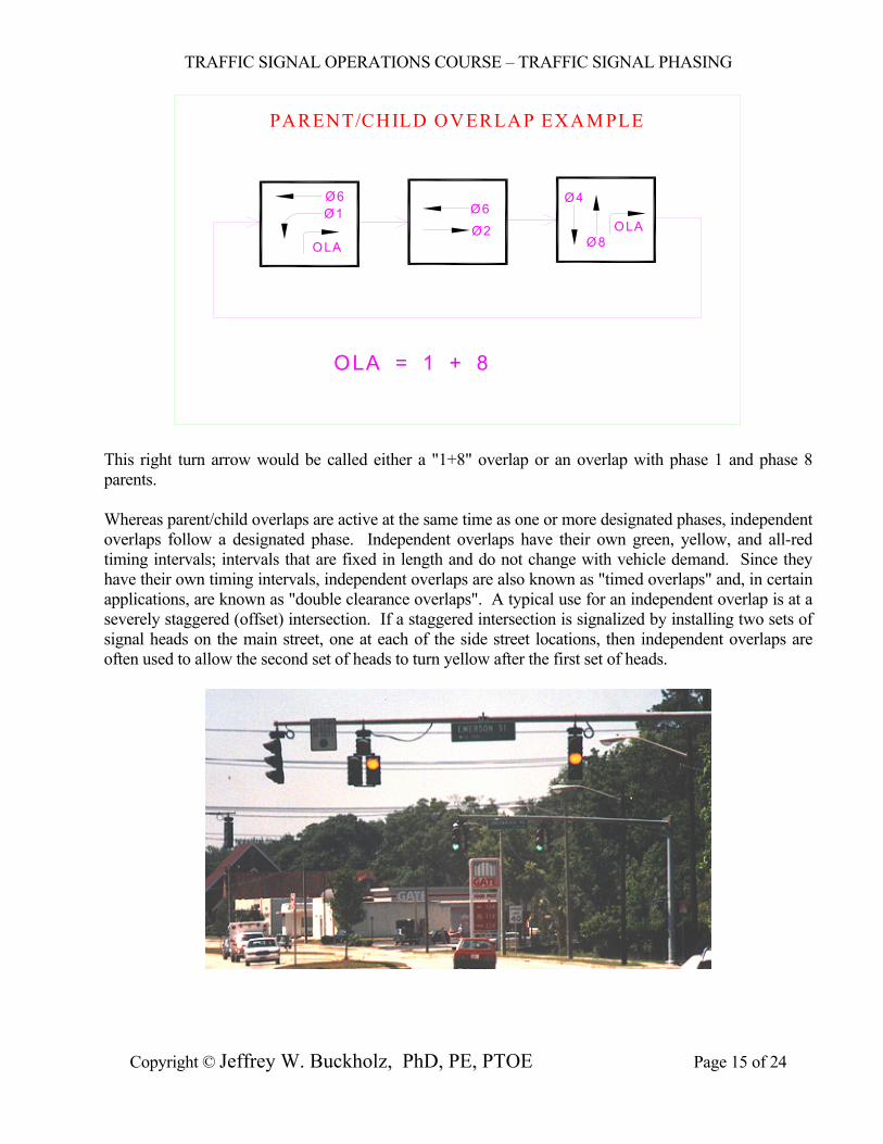
This right turn arrow would be called either a "1+8" overlap or an overlap with phase 1 and phase 8 parents. Whereas parent/child overlaps are active at the same time as one or more designated phases, independent overlaps follow a designated phase. Independent overlaps have their own green, yellow, and all-red timing intervals; intervals that are fixed in length and do not change with vehicle demand. Since they have their own timing intervals, independent overlaps are also known as "timed overlaps" and, in certain applications, are known as "double clearance overlaps". A typical use for an independent overlap is at a severely staggered (offset) intersection. If a staggered intersection is signalized by installing two sets of signal heads on the main street, one at each of the side street locations, then independent overlaps are often used to allow the second set of heads to turn yellow after the first set of heads.
TRAFFIC SIGNAL OPERATIONS COURSE – TRAFFIC SIGNAL PHASING
Copyright © Jeffrey W. Buckholz, PhD, PE, PTOE Page 16 of 24
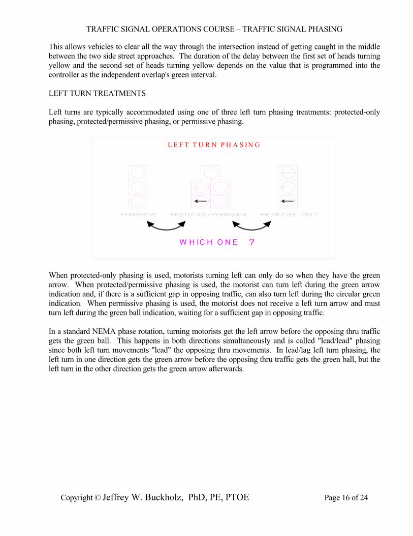
This allows vehicles to clear all the way through the intersection instead of getting caught in the middle between the two side street approaches. The duration of the delay between the first set of heads turning yellow and the second set of heads turning yellow depends on the value that is programmed into the controller as the independent overlap's green interval. LEFT TURN TREATMENTS Left turns are typically accommodated using one of three left turn phasing treatments: protected-only phasing, protected/permissive phasing, or permissive phasing.
W H IC H O N E
L E F T T U R N P H A S I N G
?
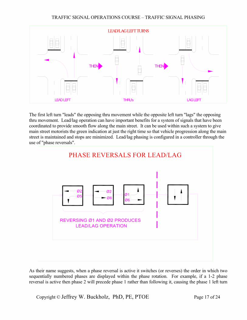
When protected-only phasing is used, motorists turning left can only do so when they have the green arrow. When protected/permissive phasing is used, the motorist can turn left during the green arrow indication and, if there is a sufficient gap in opposing traffic, can also turn left during the circular green indication. When permissive phasing is used, the motorist does not receive a left turn arrow and must turn left during the green ball indication, waiting for a sufficient gap in opposing traffic. In a standard NEMA phase rotation, turning motorists get the left arrow before the opposing thru traffic gets the green ball. This happens in both directions simultaneously and is called "lead/lead" phasing since both left turn movements "lead" the opposing thru movements. In lead/lag left turn phasing, the left turn in one direction gets the green arrow before the opposing thru traffic gets the green ball, but the left turn in the other direction gets the green arrow afterwards.
TRAFFIC SIGNAL OPERATIONS COURSE – TRAFFIC SIGNAL PHASING
Copyright © Jeffrey W. Buckholz, PhD, PE, PTOE Page 17 of 24
LEAD/LAG LEFT TURNS
THRU'sLEAD LEFT LAG LEFT
THEN THEN
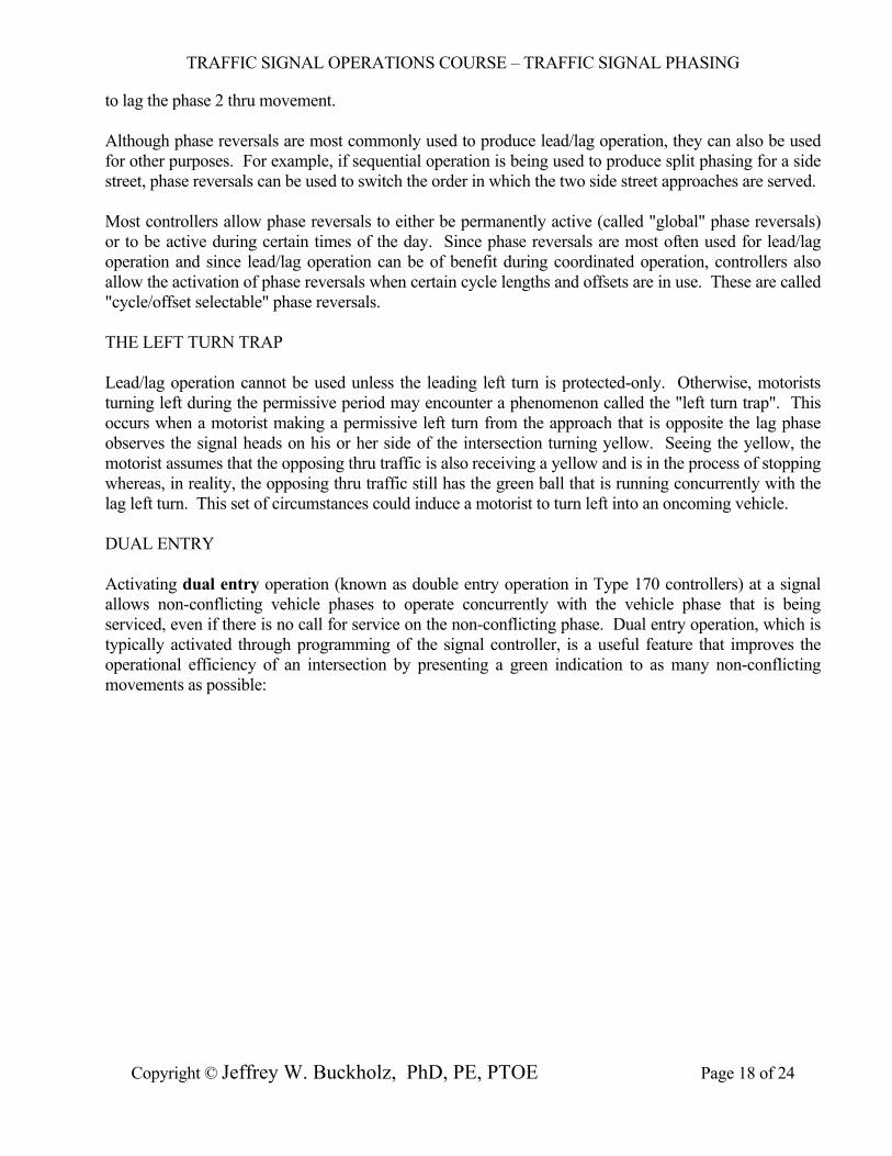
The first left turn "leads" the opposing thru movement while the opposite left turn "lags" the opposing thru movement. Lead/lag operation can have important benefits for a system of signals that have been coordinated to provide smooth flow along the main street. It can be used within such a system to give main street motorists the green indication at just the right time so that vehicle progression along the main street is maintained and stops are minimized. Lead/lag phasing is configured in a controller through the use of "phase reversals".
PHASE REVERSALS FOR LEAD/LAG
Ø5Ø2 Ø2
Ø6Ø1Ø6
REVERSING Ø1 AND Ø2 PRODUCESLEAD/LAG OPERATION
As their name suggests, when a phase reversal is active it switches (or reverses) the order in which two sequentially numbered phases are displayed within the phase rotation. For example, if a 1-2 phase reversal is active then phase 2 will precede phase 1 rather than following it, causing the phase 1 left turn
TRAFFIC SIGNAL OPERATIONS COURSE – TRAFFIC SIGNAL PHASING
Copyright © Jeffrey W. Buckholz, PhD, PE, PTOE Page 18 of 24
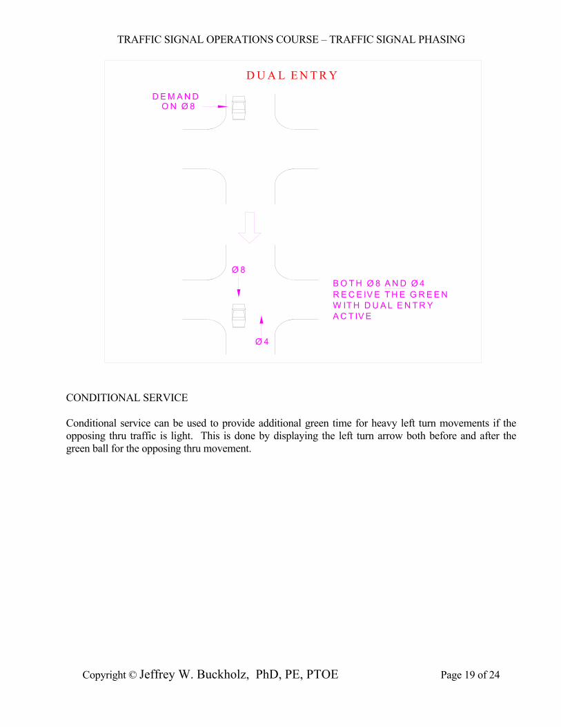
to lag the phase 2 thru movement. Although phase reversals are most commonly used to produce lead/lag operation, they can also be used for other purposes. For example, if sequential operation is being used to produce split phasing for a side street, phase reversals can be used to switch the order in which the two side street approaches are served. Most controllers allow phase reversals to either be permanently active (called "global" phase reversals) or to be active during certain times of the day. Since phase reversals are most often used for lead/lag operation and since lead/lag operation can be of benefit during coordinated operation, controllers also allow the activation of phase reversals when certain cycle lengths and offsets are in use. These are called "cycle/offset selectable" phase reversals. THE LEFT TURN TRAP Lead/lag operation cannot be used unless the leading left turn is protected-only. Otherwise, motorists turning left during the permissive period may encounter a phenomenon called the "left turn trap". This occurs when a motorist making a permissive left turn from the approach that is opposite the lag phase observes the signal heads on his or her side of the intersection turning yellow. Seeing the yellow, the motorist assumes that the opposing thru traffic is also receiving a yellow and is in the process of stopping whereas, in reality, the opposing thru traffic still has the green ball that is running concurrently with the lag left turn. This set of circumstances could induce a motorist to turn left into an oncoming vehicle. DUAL ENTRY Activating dual entry operation (known as double entry operation in Type 170 controllers) at a signal allows non-conflicting vehicle phases to operate concurrently with the vehicle phase that is being serviced, even if there is no call for service on the non-conflicting phase. Dual entry operation, which is typically activated through programming of the signal controller, is a useful feature that improves the operational efficiency of an intersection by presenting a green indication to as many non-conflicting movements as possible:
TRAFFIC SIGNAL OPERATIONS COURSE – TRAFFIC SIGNAL PHASING
Copyright © Jeffrey W. Buckholz, PhD, PE, PTOE Page 19 of 24
D U A L E N T R Y
D E M A N DO N Ø 8
Ø 8
Ø 4
B O T H Ø 8 A N D Ø 4R E C E IV E T H E G R E E NW IT H D U A L E N T R YA C T IV E
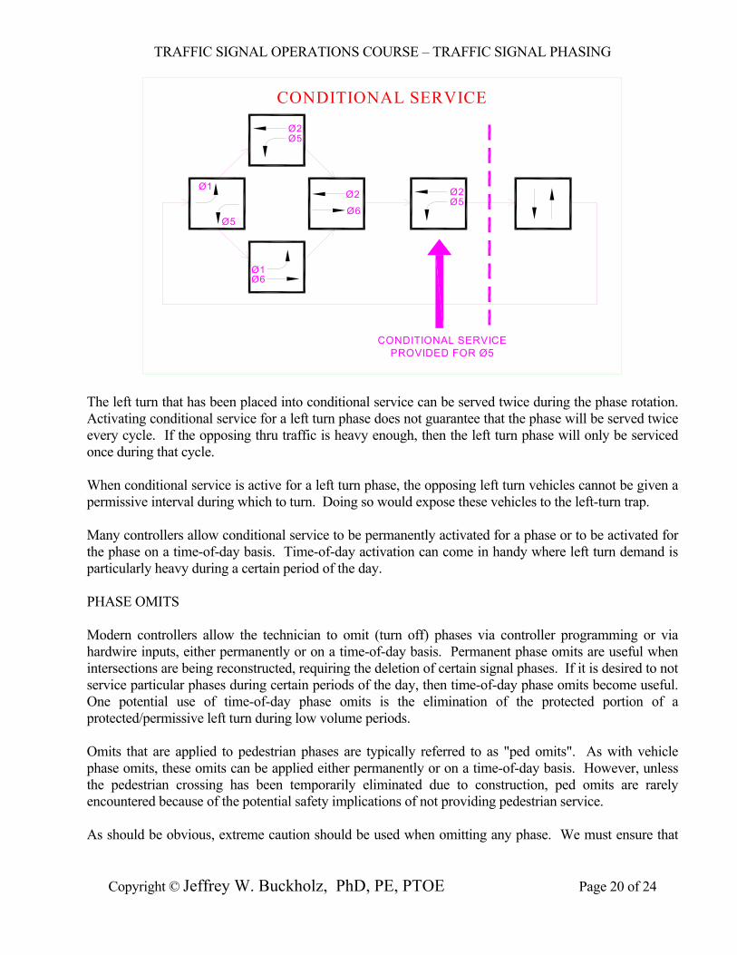
CONDITIONAL SERVICE Conditional service can be used to provide additional green time for heavy left turn movements if the opposing thru traffic is light. This is done by displaying the left turn arrow both before and after the green ball for the opposing thru movement.
TRAFFIC SIGNAL OPERATIONS COURSE – TRAFFIC SIGNAL PHASING
Copyright © Jeffrey W. Buckholz, PhD, PE, PTOE Page 20 of 24
CONDITIONAL SERVICE
Ø1
Ø5
Ø5Ø2
Ø6Ø1
Ø2
Ø6
PROVIDED FOR Ø5CONDITIONAL SERVICE
Ø2Ø5
The left turn that has been placed into conditional service can be served twice during the phase rotation. Activating conditional service for a left turn phase does not guarantee that the phase will be served twice every cycle. If the opposing thru traffic is heavy enough, then the left turn phase will only be serviced once during that cycle. When conditional service is active for a left turn phase, the opposing left turn vehicles cannot be given a permissive interval during which to turn. Doing so would expose these vehicles to the left-turn trap. Many controllers allow conditional service to be permanently activated for a phase or to be activated for the phase on a time-of-day basis. Time-of-day activation can come in handy where left turn demand is particularly heavy during a certain period of the day. PHASE OMITS Modern controllers allow the technician to omit (turn off) phases via controller programming or via hardwire inputs, either permanently or on a time-of-day basis. Permanent phase omits are useful when intersections are being reconstructed, requiring the deletion of certain signal phases. If it is desired to not service particular phases during certain periods of the day, then time-of-day phase omits become useful. One potential use of time-of-day phase omits is the elimination of the protected portion of a protected/permissive left turn during low volume periods. Omits that are applied to pedestrian phases are typically referred to as "ped omits". As with vehicle phase omits, these omits can be applied either permanently or on a time-of-day basis. However, unless the pedestrian crossing has been temporarily eliminated due to construction, ped omits are rarely encountered because of the potential safety implications of not providing pedestrian service. As should be obvious, extreme caution should be used when omitting any phase. We must ensure that
TRAFFIC SIGNAL OPERATIONS COURSE – TRAFFIC SIGNAL PHASING
Copyright © Jeffrey W. Buckholz, PhD, PE, PTOE Page 21 of 24
all vehicles and pedestrians have an opportunity to proceed safely at some point during the cycle. REST IN GREEN When there are no vehicles at an intersection, a condition that often occurs late at night, the controller will rest in whatever phase or phases have recall active. The controller is said to "rest in green" in the recall phase. When vehicle demand is sensed on a conflicting phase, a controller that is resting in green will immediately service that phase. If two or more conflicting phases have recall active then the controller will cycle between these phases. If there are no recalls, the controller will rest in green in the last phase that received service. A controller can also rest in green during concurrent operation. If two phases are operating concurrently and there is demand on one phase but not on the other, the phase without the demand will "rest in green" while waiting on the other phase to finish serving its vehicles. RED REST When there are no vehicles at an intersection, the controller can be programmed for "red rest" operation, displaying the red indication to all approaches. The controller will provide an immediate green indication to the first phase where vehicle demand is sensed. After the demand is serviced, and assuming no other demand occurs, the intersection will return to red indications on all approaches. Red revert timing is used with red rest to ensure that unreasonably short red intervals do not occur. Without some amount of red revert timing (usually between 2 and 6 seconds), the green indication could very quickly, and unexpectedly, return to a phase that had just turned red. This might surprise a driver since, once a signal turns red, most drivers expect to wait a certain amount of time before receiving the green again. START-UP PHASES The phases that will be active when the controller is first turned on, or when the controller returns from a power failure, can be programmed into the controller. Also programmable is the interval (red, yellow, or green) that these phases will be in upon start-up. One common configuration is to have the main street thru phases (2 and 6) start-up in the green interval with all other phases starting-up in red. This start-up sequence minimizes delay at an intersection since the highest traffic volumes at an intersection are typically associated with the main street thru lanes, and these lanes get the green first. Another more conservative approach is to have all phases start in red and to keep this all-red interval for a certain specified period of time (say, 5 seconds) before proceeding with normal controller sequencing. Some engineers feel that this start-up sequence is safer since it forces all vehicles to stop before any green indications are displayed. FLASHING OPERATION There are three common means whereby a traffic signal is placed into flashing operation:
TRAFFIC SIGNAL OPERATIONS COURSE – TRAFFIC SIGNAL PHASING
Copyright © Jeffrey W. Buckholz, PhD, PE, PTOE Page 22 of 24
1. When the conflict monitor senses an operational problem and places the signal in flash, the signal
is said to be in "conflict flash",
2. When a police officer or technician throws the "FLASH/AUTO" switch in the police panel to the FLASH position, the signal is said to be in "manual flash", and
3. When the controller itself sends the signal to flash because it has been programmed to do so
during low-volume periods, the signal is said to be in "program flash" (also known as "plan flash" or "remote flash").
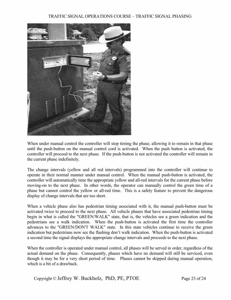
Flashing operation occurs immediately during conflict or manual flash; however, for program flash the controller must enter and exit flashing operation in a manner that is consistent with the MUTCD. Because of this, program flash is also referred to as "MUTCD flash". The phase or phases that are green immediately prior to the beginning of program flash are known as the flash entry phases. The phase or phases that are green immediately after the discontinuance of flashing operation are known as the flash exit phases. These flash exit and entry phases must be programmed into the controller. To meet MUTCD (Manual on Uniform Traffic Control Devices) requirements, the signal must enter flashing operation at the end of the main street thru phase and the main street thru phases must be the first phase displayed upon exit from program flash. MANUAL CONTROL OF TRAFFIC SIGNALS The timing of modern traffic signal controllers can be manually controlled by placing the "AUTO/MANUAL" switch located in the police panel in the "MANUAL" position and using a push-button control cord to step through the phasing sequence.
TRAFFIC SIGNAL OPERATIONS COURSE – TRAFFIC SIGNAL PHASING
Copyright © Jeffrey W. Buckholz, PhD, PE, PTOE Page 23 of 24
When under manual control the controller will stop timing the phase, allowing it to remain in that phase until the push-button on the manual control cord is activated. When the push button is activated, the controller will proceed to the next phase. If the push-button is not activated the controller will remain in the current phase indefinitely. The change intervals (yellow and all red intervals) programmed into the controller will continue to operate in their normal manner under manual control. When the manual push-button is activated, the controller will automatically time the appropriate yellow and all-red intervals for the current phase before moving-on to the next phase. In other words, the operator can manually control the green time of a phase but cannot control the yellow or all-red time. This is a safety feature to prevent the dangerous display of change intervals that are too short. When a vehicle phase also has pedestrian timing associated with it, the manual push-button must be activated twice to proceed to the next phase. All vehicle phases that have associated pedestrian timing begin in what is called the "GREEN/WALK" state, that is, the vehicles see a green indication and the pedestrians see a walk indication. When the push-button is activated the first time the controller advances to the "GREEN/DON'T WALK" state. In this state vehicles continue to receive the green indication but pedestrians now see the flashing don’t walk indication. When the push-button is activated a second time the signal displays the appropriate change intervals and proceeds to the next phase. When the controller is operated under manual control, all phases will be served in order, regardless of the actual demand on the phase. Consequently, phases which have no demand will still be serviced, even though it may be for a very short period of time. Phases cannot be skipped during manual operation, which is a bit of a drawback.
TRAFFIC SIGNAL OPERATIONS COURSE – TRAFFIC SIGNAL PHASING
Copyright © Jeffrey W. Buckholz, PhD, PE, PTOE Page 24 of 24
When the controller is operated under manual control, concurrent operation is also lost. Consider an eight phase controller in quad operation. Let's assume that both left turn arrows on the main street are currently green and that demand for the left turn is heavy in one direction but light in the other. When all of the left turns in the direction having light demand have been served we would like the opposing thru movement to get the green while the heavy left turn continues to be served, as routinely happens when the controller is operating normally. However, under manual control, both left turn arrows must be terminated at the same time before the thru phases can be served. This inability to provide concurrent phasing that is sensitive to actual vehicle demand is a more serious drawback of manual control. Police officers often use manual signal control during special events, giving large amounts of green time to the heaviest traffic movements. For example, when a football game ends and everybody leaves the stadium parking lots at once, manual control can be used to provide long green intervals on roadways leaving the stadium area.