Traffic Signal Optimization Project (Electronics … Onondaga County Department of Transportation...
28
Onondaga County Department of Transportation Traffic Signal Optimization Project (Electronics Parkway/Henry Clay Boulevard) (Future Coordinated Corridor) Prepared for: Syracuse Metropolitan Transportation Council 126 North Salina Street 100 Clinton Square, Suite 100 Syracuse, NY 13202 Prepared by: Creighton Manning Engineering, LLP 17 Computer Drive West Albany, NY 12205 October 2010
Transcript of Traffic Signal Optimization Project (Electronics … Onondaga County Department of Transportation...
Onondaga County Department of Transportation
Traffic Signal Optimization Project (Electronics Parkway/Henry Clay
Boulevard) (Future Coordinated Corridor)
Prepared for: Syracuse Metropolitan Transportation Council
126 North Salina Street 100 Clinton Square, Suite 100
Syracuse, NY 13202
Prepared by:
Creighton Manning Engineering, LLP
17 Computer Drive West Albany, NY 12205
October 2010
ii
Onondaga County Department of Transportation Traffic Signal Optimization Project (Electronics Parkway/Henry Clay Boulevard) (Future Coordinated Corridor) October 2010 This document was prepared with financial assistance from the Federal Highway Administration and the Federal Transit Administration of the U.S. Department of Transportation through the New York State Department of Transportation. The Syracuse Metropolitan Transportation Council is solely responsible for its contents.
For further information contact: Mario Colone, Project Manager Syracuse Metropolitan Transportation Council 126 N. Salina St., 100 Clinton Square, Suite 100 Syracuse, NY 13202 PHONE: (315) 422-5716; FAX: (315) 422-7753 www.smtcmpo.org

iii
Table of Contents Page Title Page ......................................................................................................................... i Table of Contents............................................................................................................ iii List of Figures..................................................................................................................iv List of Tables...................................................................................................................iv List of Appendices........................................................................................................... v
I. INTRODUCTION.................................................................................................. 1 A. Study Area ................................................................................................. 1 B. Purpose and Methodology ......................................................................... 1
II. ANALYSIS............................................................................................................ 3 A. Electronics Parkway/Old Liverpool Road/Rite Aid Driveway...................... 4 B. Electronics Parkway/Sunflower Drive ........................................................ 5 C. Electronics Parkway/7th North Street/Holiday Inn Driveway....................... 6 D. Electronics Parkway/I-90 Exit 37/Holiday Inn Driveway............................. 8 E. Electronics Parkway/Transistor Parkway ................................................. 10 F. Electronics Parkway/Continuum Drive/Limestone Drive .......................... 11 G. Electronics Parkway/Henry Clay Boulevard/Hopkins Road ..................... 13 H. Henry Clay Boulevard/Metropolitan Park Drive........................................ 14 I. Henry Clay Boulevard/West Taft Road/Vine Street ................................. 15 J. Corridor Evaluation Summary.................................................................. 17 K. Optimization Summary............................................................................. 18
III. CONCLUSIONS ................................................................................................. 21

iv
List of Figures Page
Figure 1 – Project Location and Study Area Intersections............................................... 2
List of Tables
Table II.A.1 – Electronics Pkwy/Old Liverpool Rd/Rite Aid Drwy LOS Summary ............ 4
Table II.A.2 – Electronics Pkwy/Old Liverpool Rd/Rite Aid Drwy Parameter Summary... 5
Table II.B.1 – Electronics Pkwy/Sunflower Dr LOS Summary......................................... 5
Table II.B.2 – Electronics Pkwy/Sunflower Dr Parameter Summary ............................... 6
Table II.C.1 – Electronics Pkwy/7th North St/Holiday Inn Drwy LOS Summary ............... 7
Table II.C.2 – Electronics Pkwy/7th North St/Holiday Inn Drwy Parameter Summary...... 8
Table II.D.1 – Electronics Pkwy/I-90 Exit 37/Holiday Inn Drwy LOS Summary ............... 9
Table II.D.2 – Electronics Pkwy/I-90 Exit 37/Holiday Inn Drwy Parameter Summary.... 10
Table II.E.1 – Electronics Pkwy/Transistor Pkwy LOS Summary .................................. 10
Table II.E.2 – Electronics Pkwy/Transistor Pkwy Parameter Summary......................... 11
Table II.F.1 – Electronics Pkwy/Continuum Dr/Limestone Dr LOS Summary ............... 12
Table II.F.2 – Electronics Pkwy/Continuum Dr/Limestone Dr Parameter Summary...... 13
Table II.G.1 – Electronics Pkwy/Henry Clay Blvd/Hopkins Rd LOS Summary .............. 13
Table II.G.2 – Electronics Pkwy/Henry Clay Blvd/Hopkins Rd Parameter Summary .... 14
Table II.H.1 – Henry Clay Blvd/Metropolitan Park Dr LOS Summary............................ 15
Table II.H.2 – Henry Clay Blvd/Metropolitan Park Dr Parameter Summary .................. 15
Table II.I.1 – Henry Clay Blvd/West Taft Rd/Vine St LOS Summary............................. 16
Table II.I.2 – Henry Clay Blvd/West Taft Rd/Vine St Parameter Summary ................... 17
Table II.J.1 – Measures of Effectiveness on Electronics Pkwy/Henry Clay Blvd ........... 17
Table II.K.1 – Standard Coordination Data Table (AM Peak Hour) ............................... 19
Table II.K.2 – Standard Coordination Data Table (PM Peak Hour) ............................... 19
Table II.K.3 – Clustered Coordination Data Table (AM Peak Hour) .............................. 19
Table II.K.4 – Clustered Coordination Data Table (PM Peak Hour) .............................. 20

v
List of Appendices
Appendix A......................................................................... Glossary and LOS Definitions
Appendix B.......................................................................................... Intersection Details
• Location Map • Sketch • Intersection Photos • Traffic Volumes • Signal Timings (Existing, Proposed) • Existing LOS Report • Optimized LOS Reports

OCDOT/SMTC Signal Optimization Engineers, Planners and Surveyors Electronics Pkwy/Henry Clay Blvd Corridor Study- Page 1
CHAPTER I INTRODUCTION
Outdated traffic signal timings account for a significant amount of traffic delay on urban and suburban roadways across the country. Periodically updating traffic signal equipment and timings based on new technology and current traffic volumes can provide significant benefits at a relatively low cost, alleviate the need for additional infrastructure, and reduce time spent in traffic, fuel consumption, and emissions. This report summarizes the results of a Traffic Signal Timing Optimization study conducted at various county-owned and controlled intersections along the Electronics Parkway/Henry Clay Boulevard corridor located in Onondaga County, New York.
A. Study Area The study area intersections for this report include the following, as shown on Figure 1:
Electronics Parkway/Old Liverpool Road/Rite Aid Driveway Electronics Parkway/Sunflower Drive Electronics Parkway/7th North Street/Holiday Inn Driveway Electronics Parkway/I-90 Exit 37 Ramp/Holiday Inn Driveway Electronics Parkway/Transistor Parkway Electronics Parkway/Limestone Drive/Continuum Drive Electronics Parkway/Henry Clay Boulevard/Hopkins Road Henry Clay Boulevard/Metropolitan Park Drive Henry Clay Boulevard/West Taft Road/Vine Street
B. Purpose and Methodology The purpose of this study was to update intersection signal timings in order to maximize intersection capacity, reduce driver delays, reduce vehicle emissions, and improve the overall efficiency of traffic operations for the motoring public. In order to accomplish this task, traffic count data, signal timing parameters, and intersection geometry was provided by the Syracuse Metropolitan Transportation Council (SMTC) and the Onondaga County Department of Transportation (OCDOT) to evaluate the current performance of the intersections. Adjustments in signal timings, off-sets, detection, and other parameters were made to improve intersection performance. Once adjustments were identified, changes to the field equipment could be made to implement improvements. Some adjustments, like converting from a leading protected left turn arrow to a lagging arrow will be easily noticed, while others, such as vehicle detection modifications, or minor changes in the green time allocation, may not be realized by drivers. Traffic simulation models of each intersection were developed using the Synchro 7 program. Existing traffic operations were documented and summarized and then optimization of the signals was performed. The changes in the signal timing parameters and the resulting performance changes were then documented to identify the net benefits for the actions.

F:\
Proje
cts
\2009\1
09-094 S
MT
C O
CD
OT
\cadd\d
gn\t
raf_lo
c o
verall
ele
ctr
onic
s.d
gn
N
PROJECT: DATE: 09-094d 7/10 FIGURE: 1
PROJECT LOCATION
TRAFFIC SIGNAL OPTIMIZATION
ONONDAGA COUNTY
SYRACUSE, NEW YORK
ddoran
81INTERSTATE
81INTERSTATE
s
s
695
90INTERSTATE
690
INTERSTATE
690
INTERSTATE
90INTERSTATE
ELECTRONICS PKWY/OLDLIVERPOOL RD/RITE AID DRWY
ELECTRONICS PKWY/SUNFLOWER DR
ELECTRONICS PKWY/7THNORTH ST/HOLIDAY INN DRWY
ELECTRONICS PKWY/I-90 EXIT37 RAMP/HOLIDAY INN DRWY
ELECTRONICS PKWY/TRANSISTOR PKWY
ELECTRONICS PKWY/LIMESTONE DR/CONTINUUM DR
ELECTRONICS PKWY/HENRYCLAY BLVD/HOPKINS RD
HENRY CLAY BLVD/METROPOLITAN PARK DR
HENRY CLAY BLVD/WEST TAFT RD/VINE ST

OCDOT/SMTC Signal Optimization Engineers, Planners and Surveyors Electronics Pkwy/Henry Clay Blvd Corridor Study- Page 3
CHAPTER II ANALYSIS
Traffic volume data, signal timings, intersection sketches, and photos of the study area intersections were gathered from data provided by the OCDOT and the SMTC. This information was used to create existing condition models of each intersection, which were then analyzed to determine their existing performance criteria. With the existing levels of service (LOS) established as the baseline condition, the signal was then optimized. The LOS definitions and a glossary of terms are included in Appendix A.
To maximize the efficiency and performance of each intersection, the traffic volumes
for each peak hour were evaluated using a variety of cycle lengths and timing splits. In some cases, the optimized cycle lengths resulted in each signal phase operating at its maximum green time during each cycle of the peak hour. Given that traffic volumes will vary throughout the course of the peak hour, consideration was given to adjusting the cycle length to longer cycles, allowing the signal more flexibility to alter timings as traffic conditions warrant. For example, during low levels of traffic, the controller can reduce the cycle length and serve different approaches quicker. This is particularly useful during off-peak periods. During higher levels of traffic, most notably during peak hours, the cycle length can increase to provide longer green times on approaches that have higher volumes of traffic.
The nine study area intersections on Electronics Parkway/Henry Clay Boulevard
were also evaluated to determine how the implementation of a traffic signal coordination plan would impact traffic progression through the corridor.
Changes to the existing timings, detection, or parameters such as minimums,
maximums, recalls, clearance intervals, and vehicle extensions, are presented in this chapter along with the resulting intersection performance. Changes to these parameters are based on the Onondaga County Department of Transportation’s Traffic Signal Timing Standards and the Traffic Signal Timing Manual, published by the Institute of Transportation Engineers (ITE), 2009. Appendix B includes detailed sketches, photos, controller settings, signal timings/splits, and level of service reports for each intersection.

OCDOT/SMTC Signal Optimization Engineers, Planners and Surveyors Electronics Pkwy/Henry Clay Blvd Corridor Study- Page 4
A. Electronics Parkway/Old Liverpool Road/Rite Aid Driveway This four-leg intersection operates under a four-phase traffic signal with a 140-second maximum cycle length. No recall is set, such that any phase can be skipped if no calls are placed on an approach. The southbound Electronics Parkway approach provides a shared left-turn/through lane and a separate right-turn lane while the northbound Rite Aid Driveway approach provides a single lane for shared travel movements. The westbound Old Liverpool Road approach provides a shared left-turn/through lane, a second through lane, and a separate slip right-turn lane controlled by a yield sign. The eastbound Old Liverpool Road approach provides two through lanes with shared left and right turns. Presence detection is provided on all lanes with the exception of the westbound slip right-turn lane. No sidewalks, crosswalks, or pedestrian controls are provided. The posted speed limit on Electronics Parkway and Old Liverpool Road is 40 mph. Table II.A.1 summarizes the detailed levels of service for existing and proposed conditions.
Table II.A.1 – Electronics Pkwy/Old Liverpool Rd/Rite Aid Drwy LOS Summary
AM Peak Hour PM Peak Hour Intersection
Con
trol
Existing Coordinated Existing Coordinated
Electronics Pkwy/Old Liverpool Rd/Rite Aid Drwy S Old Liverpool Road EB
Old Liverpool Road WB Rite Aid Drwy NB
Electronics Parkway SB
LT,TR LT,T LTR
LT R
C (35) D (37) D (45) C (28) A (8)
C (34) C (32) A (9)
B (18) A (9)
D (44) D (46) E (56) D (53) B (16)
D (35) D (38) B (12) C (24) A (5)
Overall C (31) C (26) D (42) C (28) Key: NB, SB, EB, WB = Northbound, Southbound, Eastbound, Westbound intersection approaches
L, T, R = Left-turn, through, and/or right-turn movements X (Y) = Level of Service (Delay, seconds per vehicle) The intersection currently operates at LOS C/D during the AM and PM peak hours, respectively, with the northbound Rite Aid Driveway operating at LOS E. After optimization of the traffic signal, the intersection will operate at LOS C during both peak hours with all movements operating at LOS D or better. To improve operations, the yellow/all-red clearance, the minimum greens, and vehicle extension were modified. In addition, the northbound and southbound split phasing was removed to allow for permitted travel movements. The signal was optimized using Synchro which resulted in an 80-second cycle length during the AM and PM peak hours. The AM and PM peak hour cycle lengths were adjusted to minimize vehicle delays, minimize the volume to capacity (v/c) ratio, and to coordinate the timings with adjacent signals located to the north. During the peak hours, the intersection will operate at the maximum cycle length during the higher percentiles of traffic, and shorter cycle lengths during lower percentiles of traffic. Table II.A.2 summarizes the suggested changes in the signal timing parameters. It is noted that there is also the potential to remove the eastbound and westbound split phasing for traffic traveling on Old Liverpool Road if it is not needed for other traffic related issues such as safety. The installation of a permitted eastbound and

OCDOT/SMTC Signal Optimization Engineers, Planners and Surveyors Electronics Pkwy/Henry Clay Blvd Corridor Study- Page 5
westbound phase would allow this intersection to operate at better overall levels of service.
Table II.A.2 – Electronics Pkwy/Old Liverpool Rd/Rite Aid Drwy Parameter Summary Parameter Existing Proposed Detection NB, SB, EB, WB No change Recall None Min SB Minimum Green 5-sec SB; 7-sec EB/WB/NB 7-sec NB; 10-sec EB/WB/SB Yellow/All Red: 4/2-sec 4/1.5-sec for 30-40-mph Vehicle Extension 3.5-sec 1.5-sec SB/EB/WB1, 1.8-sec NB2 Cycle Length 140-sec 80-sec AM; 80-sec PM
It may be necessary to modify the parameters in Table II.A.2 if Old Liverpool Road is or becomes a coordinated corridor.
B. Electronics Parkway/Sunflower Drive
This three-leg intersection operates under a two-phase traffic signal with a 59-second maximum cycle length. The northbound Electronics Parkway approach provides an exclusive left-turn lane and two through lanes with presence detection provided on the left-turn lane and a maximum recall. The southbound Electronics Parkway approach provides two through lanes with a shared right-turn lane with no detection and a maximum recall. The eastbound Sunflower Drive approach provides separate left and right turn lanes with presence detection and no recall. The eastbound phase is allowed to skip if no vehicles are detected since no recall has been set. No sidewalks, crosswalks, or pedestrian controls are provided. The posted speed limit on Electronics Parkway is 40 mph and 30 mph on Sunflower Drive. Table II.B.1 summarizes the detailed levels of service for existing and proposed conditions.
Table II.B.1 – Electronics Pkwy/Sunflower Dr LOS Summary
AM Peak Hour PM Peak Hour Intersection
Con
trol
Existing Coordinated Existing Coordinated
Electronics Pkwy/Sunflower Dr S Sunflower Drive EB
Electronics Parkway NB
Electronics Parkway SB
L R L
T,T T,TR
B (20) B (18) A (4) A (4) A (4)
B (14) B (13) A (4) A (5) A (5)
C (21) C (20) A (4) A (3) A (3)
B (15) B (14) A (4) A (3) A (4)
Overall A (6) A (6) A (4) A (4) Key: NB, SB, EB, WB = Northbound, Southbound, Eastbound, Westbound intersection approaches
L, T, R = Left-turn, through, and/or right-turn movements X (Y) = Level of Service (Delay, seconds per vehicle) The intersection currently operates at good levels of service with low delays during the AM and PM peak hours. With the addition of point detection and minimum recall
1 Max allowable headway = 3 sec, detection zone = 70 feet, approach speed = 40-45 mph. 2 Max allowable headway = 3 sec, detection zone = 30 feet, approach speed = 30 mph.

OCDOT/SMTC Signal Optimization Engineers, Planners and Surveyors Electronics Pkwy/Henry Clay Blvd Corridor Study- Page 6
on the northbound/southbound approaches, presence detection on the northbound left-turn lane, a half-cycle length, and traffic signal optimization, delay will be slightly reduced and drivers on the northbound and southbound Electronics Parkway approaches will be coordinated with the adjacent signals. This intersection will continue to operate at an overall LOS A with these improvements.
To improve operations as noted above, point detection was added to northbound and southbound Electronics Parkway through lanes, presence detection was added to the northbound left-turn lane, traffic signal coordination was provided, and the yellow/all-red clearance, minimum greens, and vehicle extension were modified. The signal was optimized using Synchro which resulted in a 40-second cycle length during the AM and PM peak hours. Review of the actuated green times indicated that each approach will generally operate below the maximum allowable split for all levels of traffic. Table II.B.2 summarizes the suggested changes in the signal timing parameters.
Table II.B.2 – Electronics Pkwy/Sunflower Dr Parameter Summary
Parameter Existing Proposed Detection EB Point detection added to NB/SB
throughs; Presence detection added to NB left
Recall Max NB/SB throughs Min NB/SB throughs Minimum Green 8-sec EB; 10-sec NB/SB throughs 7-sec EB; 10-sec NB/SB throughs Yellow/All Red: 3/3-sec 4/2-sec for 30-40 mph speed Vehicle Extension 3-sec 1.6-sec EB3; 3.8-sec NB/SB
throughs4 Cycle Length 59-sec 40-sec AM; 40-sec PM
C. Electronics Parkway/7th North Street/Holiday Inn Driveway
This four-leg intersection operates under a three-phase traffic signal with a 103-second maximum cycle length. The southbound Electronics Parkway approach provides two left-turn lanes and two through lanes with shared right-turns while the northbound approach provides an exclusive left-turn lane, two through lanes, and a separate right-turn lane. Presence detection is provided on the northbound and southbound left-turn lanes while a maximum recall is only provided on the through movements. The westbound 7th North Street approach provides a shared left-turn/through lane and a separate yield controlled right-turn lane with presence detection and no recall. The eastbound Holiday Inn Driveway approach provides two through lanes with shared left and right turns with presence detection and no recall. The eastbound and westbound phases are allowed to skip if no vehicles are detected since no recall has been set. No sidewalks, crosswalks, or pedestrian controls are provided. The posted speed limit on Electronics Parkway and 7th North Street is 40 mph. Table II.C.1 summarizes the detailed levels of service for existing and proposed conditions.
3 Max allowable headway = 3 sec, detection zone = 30 feet, approach speed = 30 mph. 4 Max allowable headway = 3 sec, detection zone = 6 feet (placed 200 feet from the intersection), approach speed = 40-45 mph.
OCDOT/SMTC Signal Optimization Engineers, Planners and Surveyors Electronics Pkwy/Henry Clay Blvd Corridor Study- Page 7
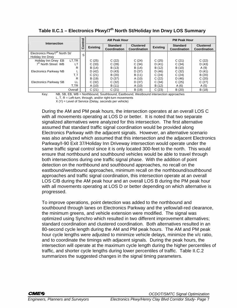
Table II.C.1 – Electronics Pkwy/7th North St/Holiday Inn Drwy LOS Summary
AM Peak Hour PM Peak Hour Intersection
Con
trol
Existing Standard Coordination
Clustered Coordination Existing Standard
Coordination Clustered
Coordination Electronics Pkwy/7th North St/ Holiday Inn Drwy S
Holiday Inn Drwy EB 7th North Street WB
Electronics Parkway NB
Electronics Parkway SB
LT,TR LT R L
T,T R
LL T,TR
C (25) C (33) B (14) D (42) C (21) B (19) C (32) A (10)
C (22) C (28) B (13) D (43) B (20) D (37) C (32) B (11)
C (24) C (34) B (14) D (37) B (11) A (10) D (37) A (10)
C (25) D (41) B (12) D (46) C (24) C (22) C (34) B (12)
C (21) C (34) B (10) C (32) C (24) D (46) C (25) A (6)
C (22) D (43) A (9)
D (41) B (20) C (20) C (27) A (5)
Overall C (21) C (21) B (19) C (23) B (20) B (18) Key: NB, SB, EB, WB = Northbound, Southbound, Eastbound, Westbound intersection approaches
L, T, R = Left-turn, through, and/or right-turn movements X (Y) = Level of Service (Delay, seconds per vehicle)
During the AM and PM peak hours, the intersection operates at an overall LOS C with all movements operating at LOS D or better. It is noted that two separate signalized alternatives were analyzed for this intersection. The first alternative assumed that standard traffic signal coordination would be provided along Electronics Parkway with the adjacent signals. However, an alternative scenario was also analyzed which assumed that this intersection and the adjacent Electronics Parkway/I-90 Exit 37/Holiday Inn Driveway intersection would operate under the same traffic signal control since it is only located 300-feet to the north. This would ensure that northbound and southbound vehicles would be able to travel through both intersections during one traffic signal phase. With the addition of point detection on the northbound and southbound approaches, no recall on the eastbound/westbound approaches, minimum recall on the northbound/southbound approaches and traffic signal coordination, this intersection operate at an overall LOS C/B during the AM peak hour and an overall LOS B during the PM peak hour with all movements operating at LOS D or better depending on which alternative is progressed.
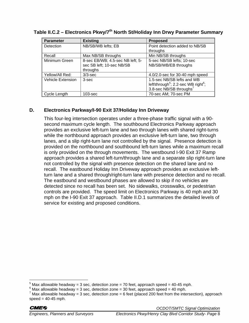
To improve operations, point detection was added to the northbound and southbound through lanes on Electronics Parkway and the yellow/all-red clearance, the minimum greens, and vehicle extension were modified. The signal was optimized using Synchro which resulted in two different improvement alternatives; standard coordination and clustered coordination. Both alternatives resulted in an 80-second cycle length during the AM and PM peak hours. The AM and PM peak hour cycle lengths were adjusted to minimize vehicle delays, minimize the v/c ratio, and to coordinate the timings with adjacent signals. During the peak hours, the intersection will operate at the maximum cycle length during the higher percentiles of traffic, and shorter cycle lengths during lower percentiles of traffic. Table II.C.2 summarizes the suggested changes in the signal timing parameters.
OCDOT/SMTC Signal Optimization Engineers, Planners and Surveyors Electronics Pkwy/Henry Clay Blvd Corridor Study- Page 8
Table II.C.2 – Electronics Pkwy/7th North St/Holiday Inn Drwy Parameter Summary Parameter Existing Proposed Detection NB/SB/WB lefts; EB Point detection added to NB/SB
throughs Recall Max NB/SB throughs Min NB/SB throughs Minimum Green 8-sec EB/WB; 4.5-sec NB left; 5-
sec SB left; 10-sec NB/SB throughs
5-sec NB/SB lefts; 10-sec NB/SB/WB/EB throughs
Yellow/All Red: 3/3-sec 4.0/2.0-sec for 30-40 mph speed Vehicle Extension 3-sec 1.5-sec NB/SB lefts and WB
left\through5; 2.2-sec WB right6; 3.8-sec NB/SB throughs7
Cycle Length 103-sec 70-sec AM; 70-sec PM D. Electronics Parkway/I-90 Exit 37/Holiday Inn Driveway
This four-leg intersection operates under a three-phase traffic signal with a 90-second maximum cycle length. The southbound Electronics Parkway approach provides an exclusive left-turn lane and two through lanes with shared right-turns while the northbound approach provides an exclusive left-turn lane, two through lanes, and a slip right-turn lane not controlled by the signal. Presence detection is provided on the northbound and southbound left-turn lanes while a maximum recall is only provided on the through movements. The westbound I-90 Exit 37 Ramp approach provides a shared left-turn/through lane and a separate slip right-turn lane not controlled by the signal with presence detection on the shared lane and no recall. The eastbound Holiday Inn Driveway approach provides an exclusive left-turn lane and a shared through/right-turn lane with presence detection and no recall. The eastbound and westbound phases are allowed to skip if no vehicles are detected since no recall has been set. No sidewalks, crosswalks, or pedestrian controls are provided. The speed limit on Electronics Parkway is 40 mph and 30 mph on the I-90 Exit 37 approach. Table II.D.1 summarizes the detailed levels of service for existing and proposed conditions.
5 Max allowable headway = 3 sec, detection zone = 70 feet, approach speed = 40-45 mph. 6 Max allowable headway = 3 sec, detection zone = 30 feet, approach speed = 40 mph. 7 Max allowable headway = 3 sec, detection zone = 6 feet (placed 200 feet from the intersection), approach speed = 40-45 mph.

OCDOT/SMTC Signal Optimization Engineers, Planners and Surveyors Electronics Pkwy/Henry Clay Blvd Corridor Study- Page 9
Table II.D.1 – Electronics Pkwy/I-90 Exit 37/Holiday Inn Drwy LOS Summary
AM Peak Hour PM Peak Hour Intersection
Con
trol
Existing Standard Coordination
Clustered Coordination Existing Standard
Coordination Clustered
Coordination Electronics Pkwy/I-90 Exit 37 Ramp/Holiday Inn Drwy S
Holiday Inn Drwy EB
I-90 Exit 37 Ramp WB
Electronics Pkwy NB
Electronics Pkwy SB
L TR LT R L
T,TR L
T,TR
C (21) C (21) C (34) A (1)
C (35) C (35) C (31) B (13)
C (24) C (24) D (45) A (1)
D (37) C (23) D (52) B (11)
C (24) C (24) D (45) A (1)
D (36) C (24) D (54) A (4)
C (27) C (26) D (36) A (0)
D (40) C (29) D (44) A (10)
C (29) C (28) D (47) A (0)
C (33) C (22) C (29) B (11)
C (23) C (23) C (27) A (0)
D (36) D (35) C (33) B (11)
Overall C (21) B (20) B (18) C (22) B (19) C (22) Key: NB, SB, EB, WB = Northbound, Southbound, Eastbound, Westbound intersection approaches
L, T, R = Left-turn, through, and/or right-turn movements X (Y.Y) = Level of Service (Delay, seconds per vehicle) During the AM and PM peak hours, the intersection operates at an overall LOS C with all movements operating at LOS D or better. It is noted that two separate signalized alternatives were analyzed for this intersection. The first alternative assumed that standard traffic signal coordination would be provided along Electronics Parkway with the adjacent signals. However, an alternative scenario was also analyzed which assumed that this intersection and the adjacent Electronics Parkway/7th North Street/Holiday Inn Driveway intersection would operate under the same traffic signal control since it is only located 300-feet to the south. This would ensure that northbound and southbound vehicles would be able to travel through both intersections during one traffic signal phase. With the addition of point detection on the northbound and southbound approaches, no recall on the eastbound/westbound approaches, minimum recall on the northbound/southbound approaches and traffic signal coordination, this intersection operate at an overall LOS B during the AM peak hour and an overall LOS B/C during the PM peak hour with all movements operating at LOS D or better depending on which alternative is progressed.
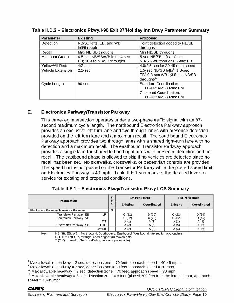
To improve operations, point detection was added to the northbound and southbound through lanes on Electronics Parkway and the yellow/all-red clearance, the minimum greens, and vehicle extension were modified. The signal was optimized using Synchro which resulted in two different improvement alternatives; standard coordination and clustered coordination. Both alternatives resulted in an 80-second cycle length during the AM and PM peak hours. The AM and PM peak hour cycle lengths were adjusted to minimize vehicle delays, minimize the v/c ratio, and to coordinate the timings with adjacent signals. During the peak hours, the intersection will operate at the maximum cycle length during the higher percentiles of traffic, and shorter cycle lengths during lower percentiles of traffic. Table II.D.2 summarizes the suggested changes in the signal timing parameters.
OCDOT/SMTC Signal Optimization Engineers, Planners and Surveyors Electronics Pkwy/Henry Clay Blvd Corridor Study- Page 10
Table II.D.2 – Electronics Pkwy/I-90 Exit 37/Holiday Inn Drwy Parameter Summary Parameter Existing Proposed Detection NB/SB lefts, EB, and WB
left/through Point detection added to NB/SB throughs
Recall Max NB/SB throughs Min NB/SB throughs Minimum Green 4.5-sec NB/SB/WB lefts; 4-sec
EB; 10-sec NB/SB throughs 5-sec NB/SB lefts; 10-sec NB/SB/WB throughs; 7-sec EB
Yellow/All Red: 4/2-sec 4.0/2.5-sec for 30-45 mph speed Vehicle Extension 2.2-sec 1.5-sec NB/SB lefts8; 1.8-sec
EB9;0.8-sec WB10;3.8-sec NB/SB throughs11
Cycle Length 90-sec Standard Coordination: 80-sec AM; 80-sec PM Clustered Coordination: 80-sec AM; 80-sec PM
E. Electronics Parkway/Transistor Parkway
This three-leg intersection operates under a two-phase traffic signal with an 87-second maximum cycle length. The northbound Electronics Parkway approach provides an exclusive left-turn lane and two through lanes with presence detection provided on the left-turn lane and a maximum recall. The southbound Electronics Parkway approach provides two through lanes with a shared right-turn lane with no detection and a maximum recall. The eastbound Transistor Parkway approach provides a single lane for shared left and right turns with presence detection and no recall. The eastbound phase is allowed to skip if no vehicles are detected since no recall has been set. No sidewalks, crosswalks, or pedestrian controls are provided. The speed limit is not posted on the Transistor Parkway while the posted speed limit on Electronics Parkway is 40 mph. Table II.E.1 summarizes the detailed levels of service for existing and proposed conditions.
Table II.E.1 – Electronics Pkwy/Transistor Pkwy LOS Summary
AM Peak Hour PM Peak Hour Intersection
Con
trol
Existing Coordinated Existing Coordinated
Electronics Parkway/Transistor Parkway S Transistor Parkway EB
Electronics Parkway NB
Electronics Parkway SB
LR L
T,T T,TR
C (22) C (22) A (1) A (3)
D (36) C (29) A (1) A (5)
C (21) C (22) A (1) A (5)
D (36) D (45) A (1) A (6)
Overall A (2) A (3) A (4) A (5) Key: NB, SB, EB, WB = Northbound, Southbound, Eastbound, Westbound intersection approaches
L, T, R = Left-turn, through, and/or right-turn movements X (Y.Y) = Level of Service (Delay, seconds per vehicle)
8 Max allowable headway = 3 sec, detection zone = 70 feet, approach speed = 40-45 mph. 9 Max allowable headway = 3 sec, detection zone = 30 feet, approach speed = 30 mph. 10 Max allowable headway = 3 sec, detection zone = 70 feet, approach speed = 30 mph. 11 Max allowable headway = 3 sec, detection zone = 6 feet (placed 200 feet from the intersection), approach speed = 40-45 mph.

OCDOT/SMTC Signal Optimization Engineers, Planners and Surveyors Electronics Pkwy/Henry Clay Blvd Corridor Study- Page 11
The intersection currently operates at good levels of service with low delays during the AM and PM peak hours. With the addition of point detection and minimum recall on the northbound/southbound through lanes and traffic signal optimization, this intersection will continue to operate at good levels of service and drivers on the northbound and southbound Electronics Parkway approaches will be coordinated with the adjacent signals.
To improve operations as noted above, point detection was added to northbound and southbound Electronics Parkway through lanes, traffic signal coordination was provided, and the yellow/all-red clearance, minimum greens, and vehicle extension were modified. The signal was optimized using Synchro which resulted in an 80-second cycle length during the AM and PM peak hours. Review of the actuated green times indicated that each approach will generally operate below the maximum allowable split for all levels of traffic. Table II.E.2 summarizes the suggested changes in the signal timing parameters.
Table II.E.2 – Electronics Pkwy/Transistor Pkwy Parameter Summary
Parameter Existing Proposed Detection NB left, EB Point detection added to NB/SB
throughs Recall Max NB/SB throughs Min NB/SB throughs Minimum Green 4.5-sec NB lefts and EB; 14-sec
NB/SB throughs 5-sec NB left; 10-sec NB/SB throughs; 7-sec EB
Yellow/All Red: 4/1-sec NB/SB; 3/1 EB and NB left 4.5/2-sec for 30-45 mph speed Vehicle Extension 2.2-sec 3.0-sec NB left12; 1.8-sec EB13;
3.8-sec NB/SB throughs14 Cycle Length 87-sec 80-sec AM; 80-sec PM
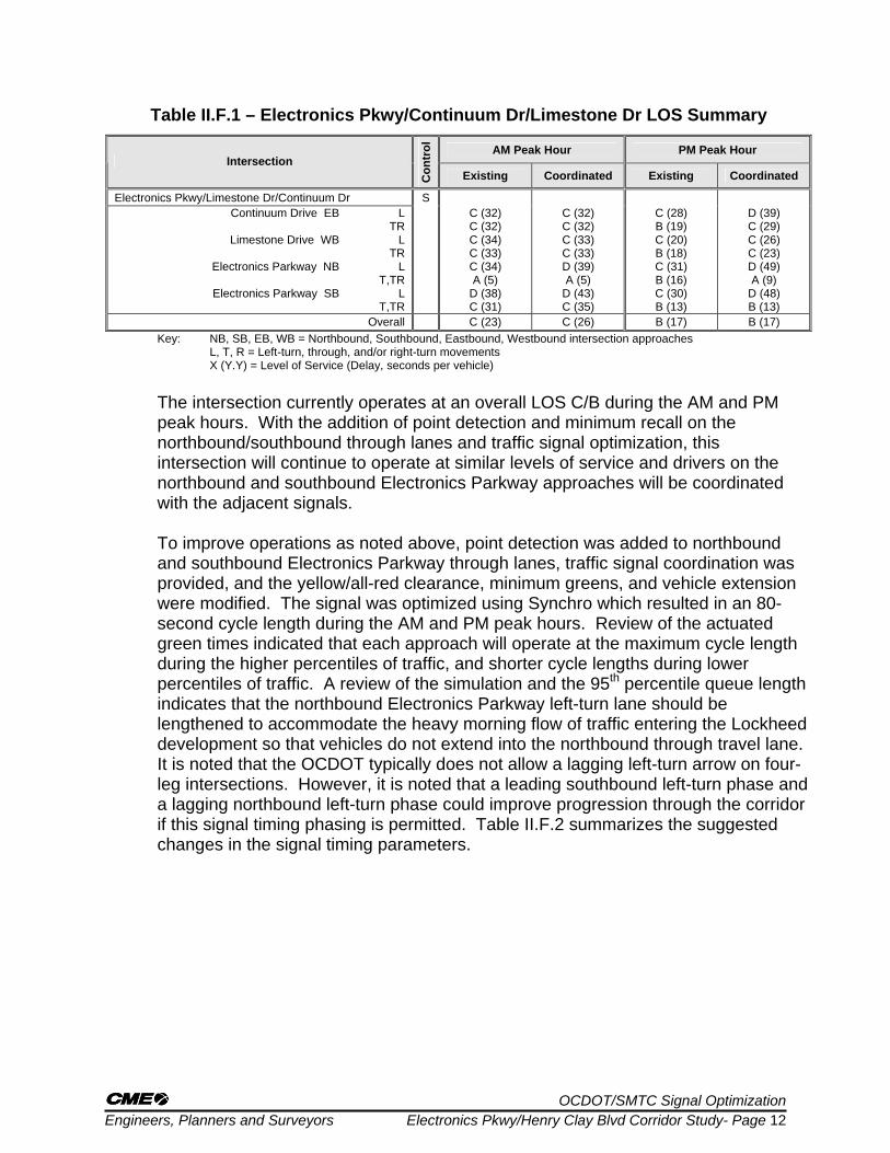
F. Electronics Parkway/Continuum Drive/Limestone Drive
This four-leg intersection operates under a three-phase traffic signal with a 96-second maximum cycle length. The northbound and southbound Electronics Parkway approaches provide an exclusive left-turn lane and two through lanes with shared right-turns. Presence detection is provided on the northbound and southbound left-turn lanes while a maximum recall is only provided on the through movements. The eastbound Continuum Drive approach and the westbound Limestone Drive approach provide an exclusive left-turn lane and a shared through/right-turn lane with presence detection and no recall. The eastbound and westbound phases are allowed to skip if no vehicles are detected since no recall has been set. No sidewalks, crosswalks, or pedestrian controls are provided. The posted speed limit on Electronics Parkway is 45 mph and presumed to be 20 to 30 mph on Continuum Drive and Limestone Drive. Table II.F.1 summarizes the detailed levels of service for existing and proposed conditions.
12 Max allowable headway = 3 sec, detection zone = 30 feet, approach speed = 45-50 mph. 13 Max allowable headway = 3 sec, detection zone = 30 feet, approach speed = 30 mph. 14 Max allowable headway = 3 sec, detection zone = 6 feet (placed 200 feet from the intersection), approach speed = 45-50 mph.
OCDOT/SMTC Signal Optimization Engineers, Planners and Surveyors Electronics Pkwy/Henry Clay Blvd Corridor Study- Page 12
Table II.F.1 – Electronics Pkwy/Continuum Dr/Limestone Dr LOS Summary
AM Peak Hour PM Peak Hour Intersection
Con
trol
Existing Coordinated Existing Coordinated
Electronics Pkwy/Limestone Dr/Continuum Dr S Continuum Drive EB
Limestone Drive WB
Electronics Parkway NB
Electronics Parkway SB
LTR
L TR
L T,TR
L T,TR
C (32) C (32) C (34) C (33) C (34) A (5)
D (38) C (31)
C (32) C (32) C (33) C (33) D (39) A (5)
D (43) C (35)
C (28) B (19) C (20) B (18) C (31) B (16) C (30) B (13)
D (39) C (29) C (26) C (23) D (49) A (9)
D (48) B (13)
Overall C (23) C (26) B (17) B (17) Key: NB, SB, EB, WB = Northbound, Southbound, Eastbound, Westbound intersection approaches
L, T, R = Left-turn, through, and/or right-turn movements X (Y.Y) = Level of Service (Delay, seconds per vehicle) The intersection currently operates at an overall LOS C/B during the AM and PM peak hours. With the addition of point detection and minimum recall on the northbound/southbound through lanes and traffic signal optimization, this intersection will continue to operate at similar levels of service and drivers on the northbound and southbound Electronics Parkway approaches will be coordinated with the adjacent signals.
To improve operations as noted above, point detection was added to northbound and southbound Electronics Parkway through lanes, traffic signal coordination was provided, and the yellow/all-red clearance, minimum greens, and vehicle extension were modified. The signal was optimized using Synchro which resulted in an 80-second cycle length during the AM and PM peak hours. Review of the actuated green times indicated that each approach will operate at the maximum cycle length during the higher percentiles of traffic, and shorter cycle lengths during lower percentiles of traffic. A review of the simulation and the 95th percentile queue length indicates that the northbound Electronics Parkway left-turn lane should be lengthened to accommodate the heavy morning flow of traffic entering the Lockheed development so that vehicles do not extend into the northbound through travel lane. It is noted that the OCDOT typically does not allow a lagging left-turn arrow on four-leg intersections. However, it is noted that a leading southbound left-turn phase and a lagging northbound left-turn phase could improve progression through the corridor if this signal timing phasing is permitted. Table II.F.2 summarizes the suggested changes in the signal timing parameters.

OCDOT/SMTC Signal Optimization Engineers, Planners and Surveyors Electronics Pkwy/Henry Clay Blvd Corridor Study- Page 13
Table II.F.2 – Electronics Pkwy/Continuum Dr/Limestone Dr Parameter Summary Parameter Existing Proposed Detection NB/SB lefts, EB/WB Point detection added to NB/SB
throughs Recall Max NB/SB throughs Min NB/SB throughs Minimum Green 4.5-sec NB/SB lefts; 12-sec NB/SB
throughs; 6-sec EB/WB 5-sec NB/SB left; 10-sec NB/SB throughs; 10-sec EB/WB
Yellow/All Red: 4/2-sec NB/SB; 3/2 EB/WB and NB/SB lefts
4.5/2-sec for 30-45 mph speed
Vehicle Extension 2.0-sec 1.5-sec NB/SB lefts15; 1.8-sec EB/WB16; 3.8-sec NB/SB throughs17
Cycle Length 96-sec 70-sec AM; 70-sec PM G. Electronics Parkway/Henry Clay Boulevard/Hopkins Road
This three-leg intersection operates under a three-phase traffic signal with a 93-second maximum cycle length. The southbound Henry Clay Boulevard approach provides an exclusive left-turn lane and two through lanes with presence detection provided on the left-turn lane and maximum recall on the through movement. The northbound Electronics Parkway approach provides two through lanes with a shared right-turn lane with no detection and maximum recall. The westbound Hopkins Road approach provides separate left and right turn lanes with presence detection and no recall. The westbound phase is allowed to skip if no vehicles are detected since no recall has been set. No sidewalks, crosswalks, or pedestrian controls are provided. The posted speed limit on the Electronics Parkway and Henry Clay Boulevard is 45 mph and 40 mph on Hopkins Road. Table II.G.1 summarizes the detailed levels of service for existing and proposed conditions.
Table II.G.1 – Electronics Pkwy/Henry Clay Blvd/Hopkins Rd LOS Summary
AM Peak Hour PM Peak Hour Intersection
Con
trol
Existing Coordinated Existing Coordinated
Electronics Pkwy/Henry Clay Blvd/Hopkins Rd S Hopkins Road WB
Electronics Parkway NB
Henry Clay Boulevard SB
LR
T,TR L
T,T
C (32) C (28) A (9)
C (32) A (3)
C (35) B (19) A (7)
D (42) A (2)
C (30) C (28) B (12) C (31) A (3)
C (32) C (20) A (7)
C (25) A (6)
Overall A (9) A (8) B (11) A (9) Key: NB, SB, EB, WB = Northbound, Southbound, Eastbound, Westbound intersection approaches
L, T, R = Left-turn, through, and/or right-turn movements X (Y.Y) = Level of Service (Delay, seconds per vehicle) The intersection currently operates at an overall LOS A/B during the AM and PM peak hours. With the addition of point detection and minimum recall on the northbound/southbound through lanes and traffic signal optimization, this
15 Max allowable headway = 3 sec, detection zone = 70 feet, approach speed = 45-50 mph. 16 Max allowable headway = 3 sec, detection zone = 30 feet, approach speed = 20 to 30 mph. 17 Max allowable headway = 3 sec, detection zone = 6 feet (placed 200 feet from the intersection), approach speed = 40-45 mph.

OCDOT/SMTC Signal Optimization Engineers, Planners and Surveyors Electronics Pkwy/Henry Clay Blvd Corridor Study- Page 14
intersection will operate at an overall LOS A during both peak hours and drivers on the northbound and southbound Electronics Parkway approaches will be coordinated with the adjacent signals. To improve operations as noted above, point detection was added to northbound and southbound Electronics Parkway through lanes, traffic signal coordination was provided, and the yellow/all-red clearance, minimum greens, and vehicle extension were modified. The signal was optimized using Synchro which resulted in an 80-second cycle length during the AM and PM peak hours. Review of the actuated green times indicated that each approach will generally operate below the maximum allowable split for all levels of traffic. Table II.G.2 summarizes the suggested changes in the signal timing parameters.
Table II.G.2 – Electronics Pkwy/Henry Clay Blvd/Hopkins Rd Parameter Summary
Parameter Existing Proposed Detection SB lefts, WB Point detection added to NB/SB
throughs Recall Max NB/SB throughs Min NB/SB throughs Minimum Green 4.5-sec SB left; 12-sec NB/SB
throughs; 6-sec WB 5-sec SB left; 10-sec NB/SB throughs; 10-sec WB
Yellow/All Red: 4/2-sec NB/SB; 3/2 WB and SB lefts
4.5/2-sec for 40-45 mph speed
Vehicle Extension 2.0-sec 1.5-sec SB left18; 1.4-sec WB19; 3.8-sec NB/SB throughs20
Cycle Length 93-sec 80-sec AM; 80-sec PM H. Henry Clay Boulevard/Metropolitan Park Drive
This three-leg intersection operates under a two-phase traffic signal with a 68-second maximum cycle length. The southbound Henry Clay Boulevard approach provides two through lanes with a shared left-turn lane while the northbound Henry Clay Boulevard approach provides two through lanes with a shared right-turn lane. Presence detection and maximum recall is provided on the northbound and southbound movements. The westbound Metropolitan Park Drive approach provides a single lane for shared left and right turns with presence detection and no recall. The westbound phase is allowed to skip if no vehicles are detected since no recall has been set. No sidewalks, crosswalks, or pedestrian controls are provided. The posted speed limit on Henry Clay Boulevard is 45 mph and 30 mph on Metropolitan Park Drive. Table II.H.1 summarizes the detailed levels of service for existing and proposed conditions.
18 Max allowable headway = 3 sec, detection zone = 70 feet, approach speed = 45-50 mph. 19 Max allowable headway = 3 sec, detection zone = 30 feet, approach speed = 40 mph. 20 Max allowable headway = 3 sec, detection zone = 6 feet (placed 200 feet from the intersection), approach speed = 45-50 mph.
OCDOT/SMTC Signal Optimization Engineers, Planners and Surveyors Electronics Pkwy/Henry Clay Blvd Corridor Study- Page 15
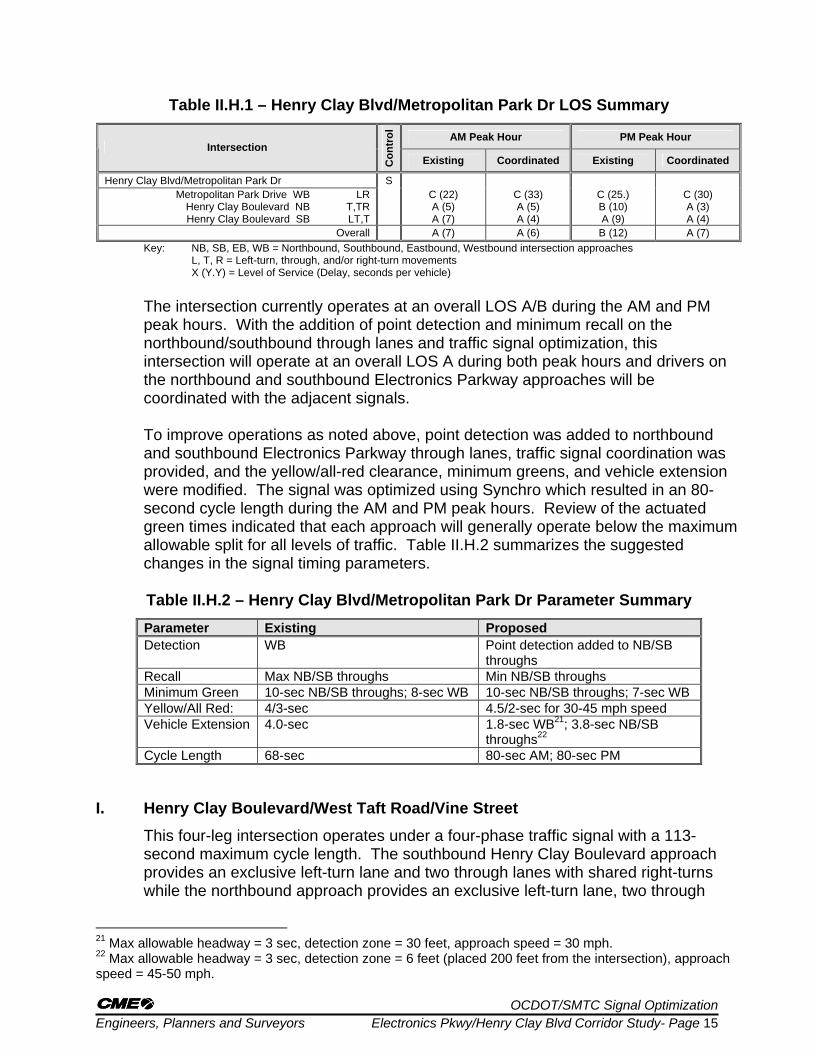
Table II.H.1 – Henry Clay Blvd/Metropolitan Park Dr LOS Summary
AM Peak Hour PM Peak Hour Intersection
Con
trol
Existing Coordinated Existing Coordinated
Henry Clay Blvd/Metropolitan Park Dr S Metropolitan Park Drive WB
Henry Clay Boulevard NB Henry Clay Boulevard SB
LR T,TR LT,T
C (22) A (5) A (7)
C (33) A (5) A (4)
C (25.) B (10) A (9)
C (30) A (3) A (4)
Overall A (7) A (6) B (12) A (7) Key: NB, SB, EB, WB = Northbound, Southbound, Eastbound, Westbound intersection approaches
L, T, R = Left-turn, through, and/or right-turn movements X (Y.Y) = Level of Service (Delay, seconds per vehicle) The intersection currently operates at an overall LOS A/B during the AM and PM peak hours. With the addition of point detection and minimum recall on the northbound/southbound through lanes and traffic signal optimization, this intersection will operate at an overall LOS A during both peak hours and drivers on the northbound and southbound Electronics Parkway approaches will be coordinated with the adjacent signals. To improve operations as noted above, point detection was added to northbound and southbound Electronics Parkway through lanes, traffic signal coordination was provided, and the yellow/all-red clearance, minimum greens, and vehicle extension were modified. The signal was optimized using Synchro which resulted in an 80-second cycle length during the AM and PM peak hours. Review of the actuated green times indicated that each approach will generally operate below the maximum allowable split for all levels of traffic. Table II.H.2 summarizes the suggested changes in the signal timing parameters.
Table II.H.2 – Henry Clay Blvd/Metropolitan Park Dr Parameter Summary Parameter Existing Proposed Detection WB Point detection added to NB/SB
throughs Recall Max NB/SB throughs Min NB/SB throughs Minimum Green 10-sec NB/SB throughs; 8-sec WB 10-sec NB/SB throughs; 7-sec WB Yellow/All Red: 4/3-sec 4.5/2-sec for 30-45 mph speed Vehicle Extension 4.0-sec 1.8-sec WB21; 3.8-sec NB/SB
throughs22 Cycle Length 68-sec 80-sec AM; 80-sec PM
I. Henry Clay Boulevard/West Taft Road/Vine Street
This four-leg intersection operates under a four-phase traffic signal with a 113-second maximum cycle length. The southbound Henry Clay Boulevard approach provides an exclusive left-turn lane and two through lanes with shared right-turns while the northbound approach provides an exclusive left-turn lane, two through
21 Max allowable headway = 3 sec, detection zone = 30 feet, approach speed = 30 mph. 22 Max allowable headway = 3 sec, detection zone = 6 feet (placed 200 feet from the intersection), approach speed = 45-50 mph.

OCDOT/SMTC Signal Optimization Engineers, Planners and Surveyors Electronics Pkwy/Henry Clay Blvd Corridor Study- Page 16
lanes, and a right-turn lane. Presence detection is provided on all northbound and southbound movements while maximum recall is provided on the through movements. The westbound West Taft Road approach provides two exclusive left-turn lanes and two through lanes with shared right-turns that flare at the intersection and are controlled by a yield sign. The eastbound Vine Street approach provides an exclusive left-turn lane, a through lane, and a separate slip right-turn lane that is controlled by a yield sign. Presence detection is provided on all of the eastbound and westbound movements with the exception of the right-turn movements. The eastbound and westbound phases are allowed to skip if no vehicles are detected since no recall has been set. No sidewalks, crosswalks, or pedestrian controls are provided. The posted speed limit on the Henry Clay Boulevard, West Taft Road, and Vine Street is 40 mph. Table II.I.1 summarizes the detailed levels of service for existing and proposed conditions.
Table II.I.1 – Henry Clay Blvd/West Taft Rd/Vine St LOS Summary
AM Peak Hour PM Peak Hour Intersection
Con
trol
Existing Coordinated Existing Coordinated
Henry Clay Blvd/West Taft Rd/Vine St S Vine Street EB
West Taft Road WB
Henry Clay Boulevard NB
Henry Clay Boulevard SB
L T R
L,L T,TR
L T,T
R L
T,TR
D (49) D (39) A (0)
D (47) C (31) D (45) D (37) C (21) D (48) D (37)
D (36) C (35) A (0)
D (40) C (25) D (47) D (39) D (54) D (47) C (29)
D (52) D (46) A (0)
D (52) D (40) D (54) E (62) C (32) E (58) D (41)
D (42) D (54) A (0)
D (55) C (31) D (49) D (46) C (28) D (52) C (28)
Overall D (36) C (34) D (47) D (39) Key: NB, SB, EB, WB = Northbound, Southbound, Eastbound, Westbound intersection approaches
L, T, R = Left-turn, through, and/or right-turn movements X (Y.Y) = Level of Service (Delay, seconds per vehicle) During the AM and PM peak hours, the intersection operates at an overall LOS D with all movements operating at LOS D or better, with the exception of the northbound through movement and the southbound left-turn movement which operates at LOS E during the PM peak hour. With no recall provided on the eastbound/westbound approaches and minimum recall on the northbound/southbound approaches, drivers on Henry Clay Boulevard will be served more frequently when gaps appear in Vine Street/West Taft Road traffic and overall delay will be reduced. To improve operations, the yellow/all-red clearance, the minimum greens, and vehicle extension were modified. The signal was optimized using Synchro which resulted in two different improvement scenarios. The signal was optimized using Synchro which resulted in an 80-second cycle length during the AM and PM peak hours. Review of the actuated green times indicated that each approach will operate at the maximum cycle length during the higher percentiles of traffic, and shorter cycle lengths during lower percentiles of traffic. Table II.I.2 summarizes the suggested changes in the signal timing parameters.

OCDOT/SMTC Signal Optimization Engineers, Planners and Surveyors Electronics Pkwy/Henry Clay Blvd Corridor Study- Page 17
Table II.I.2 – Henry Clay Blvd/West Taft Rd/Vine St Parameter Summary Parameter Existing Proposed Detection NB/SB; EB/WB lefts and throughs No change Recall Min EB/WB throughs Min NB/SB throughs Minimum Green 5-sec NB/SB/EB/WB lefts; 10-sec
NB/SB/EB/WB throughs No change
Yellow/All Red: 3.5/1.5-sec NB/SB/EB/WB lefts; 3.5/2 NB/SB/EB/WB throughs
4.5/1.5-sec for 40-45 mph speed
Vehicle Extension 3.5-sec NB/SB/EB/WB lefts; 5.0-sec EB/WB throughs; 6.0-sec SB through; 4-sec NB through
1.5-sec SB/EB/WB23; 1.7-sec NB24
Cycle Length 113-sec 80-sec AM; 80-sec PM J. Corridor Evaluation Summary
Measures of effectiveness (MOEs) serve as performance measures for evaluating the Electronics Parkway/Henry Clay Boulevard corridor. The MOEs can include delays, fuel consumption, average speed, emissions, travel time, and the “performance index” (PI) from the traffic simulation model. The PI represents a combination of the delays, stops, and queuing penalty. A lower PI indicates better overall operations. The corridor was optimized and evaluated with coordination. Table II.J.1 summarizes the MOEs for Electronics Parkway/Henry Clay Boulevard for the standard coordinated alternative and the clustered coordinated alternative.
Table II.J.1 – Measures of Effectiveness on Electronics Pkwy/Henry Clay Blvd AM Peak Hour PM Peak Hour Measure of
Effectiveness Existing Standard Coordination
Clustered Coordination Existing Standard
Coordination Clustered
Coordination
Total Delay (Hours) 75 63 63 87 62 65
Performance Index 95.6 83.0 81.8 111.2 84.2 89.3
Fuel Consumed (gal) 267 254 247 311 280 293
Overall Speed (mph)
NB
SB
23
22
25
24
25
24
22
23
26
26
25
26
Travel Time (seconds)
NB
SB
323
357
288
316
281
310
359
365
302
304
314
297
Overall, Table II.J.1 shows that the MOEs along Electronics Parkway/Henry Clay Boulevard will improve under both coordinated systems. Total delay through the corridor will be reduced and speeds will improve from 2 to 4-mph based on peak hour and approach. 23 Max allowable headway = 3 sec, detection zone = 70 feet, approach speed = 40-45 mph. 24 Max allowable headway = 3 sec, detection zone = 55 feet, approach speed = 40-45 mph.

OCDOT/SMTC Signal Optimization Engineers, Planners and Surveyors Electronics Pkwy/Henry Clay Blvd Corridor Study- Page 18
K. Optimization Summary The recommendations discussed in the preceding sections are intended to develop
consistency in the operations of each signal, improve responsiveness, and increase efficiency. The addition of detection on all approaches enables a signal to respond to changing traffic conditions, which increases the capacity of the intersection. Once vehicle detection is installed, recall settings in the signal controller can be used to create a minimum operating condition that the signal must serve. Beyond that, the controller can respond to the current demand.
Another key component of the recommendations is updating the vehicle extension
times to accurately reflect the existing or proposed detection. The vehicle extension adds time to an approach that has already served the initial platoon of traffic with the minimum green, but continues to see additional vehicles arriving on the approach. The traffic signal will not start to “gap out” (i.e. end the current phase) until the vehicle has left the detection zone.
Many of the intersections included in this analysis currently have presence detection
(long vehicle detection loops, typically 60 to 70 feet) and a 3 or 4 second vehicle extension time. Depending on the speed of approaching vehicles, this combination of presence detection and a 3 to 4 second vehicle extension will result in the continued extension of the green phase for a dwindling amount of vehicles, which increases the delay for drivers on conflicting approaches waiting for straggling vehicles to pass through the intersection. Therefore, this report generally recommends that the vehicle extension time be reduced to 0.8 to 3.0 seconds for presence detection to allow the signal to serve all approaches more efficiently and reduce overall delay at the intersection.
In contrast, point detection uses a small detection zone; typically a 6-foot detector
loop placed 100 to 200 feet from the intersection, and has a much shorter period of detection as a vehicle passes over it. Point detection requires longer vehicle extensions, since the detector has less time to detect a vehicle approaching the intersection. Therefore, for point detection, this report generally recommends using a 3.8-second vehicle extension time to allow the signal to serve all approaches more efficiently and reduce overall delay at the intersection.
Tables II.K.1-2 and Tables II.K.3-4 provide the traffic signal coordination plans for
the AM and PM peak hours for the standard coordinated alternative and the clustered coordinated alternative.

OCDOT/SMTC Signal Optimization Engineers, Planners and Surveyors Electronics Pkwy/Henry Clay Blvd Corridor Study- Page 19
Table II.K.1 – Standard Coordination Data Table (AM Peak Hour) AM Peak Hour – 80 Second Cycle Length (7:00 to 9:00 AM)
Splits Intersection
Ø1 Ø2 Ø3 Ø4 Ø5 Ø6 Ø7 Ø8 Offset
Old Liverpool Rd 19 17 44 44 64 Sunflower Dr 25 15 8 7th North St/Holiday Inn Drwy 24 26 30 11 39 10 I-90 Exit 37/Holiday inn Drwy 22 33 25 12 43 25 0 Transistor Pkwy 12 54 14 76 Continuum Dr/Limestone Dr 12 51 17 29 34 56 Hopkins Rd 19 41 20 60 48 Metropolitan Park Dr 63 17 4 West Taft Rd/Vine St 14 23 13 30 15 22 22 21 76
Table II.K.2 – Standard Coordination Data Table (PM Peak Hour)
PM Peak Hour – 80 Second Cycle Length (4:00 to 6:00 PM) Splits
Intersection Ø1 Ø2 Ø3 Ø4 Ø5 Ø6 Ø7 Ø8
Offset
Old Liverpool Rd 19 21 40 40 23 Sunflower Dr 27 13 16 7th North St/Holiday Inn Drwy 24 24 32 11 37 6 I-90 Exit 37/Holiday inn Drwy 30 30 20 12 48 20 0 Transistor Pkwy 12 54 14 20 Continuum Dr/Limestone Dr 12 39 29 12 39 28 Hopkins Rd 16 47 17 63 28 Metropolitan Park Dr 49 31 52 West Taft Rd/Vine St 16 19 16 29 12 23 20 25 24
Table II.K.3 – Clustered Coordination Data Table (AM Peak Hour)
AM Peak Hour – 80 Second Cycle Length (7:00 to 9:00 AM) Splits
Intersection Ø1 Ø2 Ø3 Ø4 Ø5 Ø6 Ø7 Ø8
Offset
Old Liverpool Rd 19 17 44 44 58 Sunflower Dr 25 15 18 7th North St/Holiday Inn Drwy 24 31 25 12 43 25 0 I-90 Exit 37/Holiday inn Drwy 24 31 25 12 43 25 0 Transistor Pkwy 25 41 14 64 Continuum Dr/Limestone Dr 12 51 17 30 33 52 Hopkins Rd 19 41 20 60 58 Metropolitan Park Dr 63 17 10 West Taft Rd/Vine St 14 23 13 30 15 22 21 22 4

OCDOT/SMTC Signal Optimization Engineers, Planners and Surveyors Electronics Pkwy/Henry Clay Blvd Corridor Study- Page 20
Table II.K.4 – Clustered Coordination Data Table (PM Peak Hour) PM Peak Hour – 80 Second Cycle Length (4:00 to 6:00 PM)
Splits Intersection
Ø1 Ø2 Ø3 Ø4 Ø5 Ø6 Ø7 Ø8 Offset
Old Liverpool Rd 19 21 40 40 38 Sunflower Dr 27 13 18 7th North St/Holiday Inn Drwy 27 25 28 12 40 28 0 I-90 Exit 37/Holiday inn Drwy 27 25 28 12 40 28 0 Transistor Pkwy 16 50 14 26 Continuum Dr/Limestone Dr 12 39 29 12 39 30 Hopkins Rd 16 47 17 63 50 Metropolitan Park Dr 49 31 78 West Taft Rd/Vine St 15 20 16 29 12 23 20 25 40
The tables above illustrate the differences in the standard and cluster coordination tables. It is noted that the splits for the standard coordination plan at the 7th North Street/Holiday Inn Driveway and I-90 Exit 37/Holiday Inn Driveway on Electronics Boulevard are similar and the offsets are very close to each other for the AM and PM peak hours (ten seconds for the AM peak hour and six seconds for the PM peak hour). This indicates that the northbound and southbound coordinated approaches will have slightly staggered green phases which will allow vehicles to travel through the adjacent intersection without stopping. The clustered coordination plan shows that these two traffic signals would have the same exact splits which would turn green at the same exact time for the northbound and southbound movements as evidence by the zero offset. For example, a motorist stopped at the 7th North Street/Holiday Inn Driveway intersection traveling northbound on Electronics Boulevard would receive a green light at the same time as the traffic signal at the I-90 Exit 37/Holiday Inn Driveway intersection.

OCDOT/SMTC Signal Optimization Engineers, Planners and Surveyors Electronics Pkwy/Henry Clay Blvd Corridor Study- Page 21
CHAPTER IV CONCLUSIONS
Based on the results of this Traffic Signal Timing Optimization study, the following recommendations are offered for the study area intersections:
• Electronics Parkway/Old Liverpool Road/Rite Aid Driveway: This intersection currently operates at LOS C/D during the AM and PM peak hours, respectively, with the northbound Rite Aid Driveway operating at LOS E. It is recommended that the northbound and southbound split phasing be removed to allow for permitted travel movements and that the timing parameters be adjusted as shown in Table II.A.2 to minimize vehicle delays, minimize the v/c ratio, and coordinate the timings with adjacent signals for the coordinated condition. These changes will result in continued acceptable overall operating conditions with all movements operating at LOS D or better during both peak hours. It is noted that there is also the potential to remove the eastbound and westbound split phasing for traffic traveling on Old Liverpool Road if it is not needed for other traffic related issues such as safety. The installation of a permitted eastbound and westbound phase would allow this intersection to operate at better overall levels of service.
• Electronics Parkway/Sunflower Drive: This intersection currently operates at
acceptable levels of service during the AM and PM peak hours. However it is recommended that the timing parameters be adjusted as shown in Table II.B.2 to minimize vehicle delays, minimize the v/c ratio, and coordinate the timings with adjacent signals. These changes will result in continued acceptable operating conditions.
• Electronics Parkway/7th North Street/Holiday Inn Driveway: During the AM and PM peak hours, this intersection operates at an overall LOS C with all movements operating at LOS D or better. It is noted that two separate signalized alternatives were analyzed for this intersection. The first alternative assumed that standard traffic signal coordination would be provided along Electronics Parkway with the adjacent signals while a second alternative scenario was analyzed which assumed that this intersection and the adjacent Electronics Parkway/7th North Street/Holiday Inn Driveway intersection would operate under the same traffic signal control since it is only located 300-feet to the north. This would ensure that northbound and southbound vehicles would be able to travel through both intersections during one traffic signal phase. It is recommended that the timing parameters be adjusted as shown in Table II.C.2 to minimize vehicle delays, minimize the v/c ratio, and coordinate the timings with adjacent signals. These changes will result in continued acceptable operating conditions for either the standard coordination or clustered coordination scenarios.
• Electronics Parkway/I-90 Exit 37/Holiday Inn Driveway: During the AM and PM peak
hours, this intersection operates at an overall LOS C with all movements operating at LOS D or better. It is noted that two separate signalized alternatives were

OCDOT/SMTC Signal Optimization Engineers, Planners and Surveyors Electronics Pkwy/Henry Clay Blvd Corridor Study- Page 22
analyzed for this intersection. The first alternative assumed that standard traffic signal coordination would be provided along Electronics Parkway with the adjacent signals, while a second alternative scenario was analyzed which assumed that this intersection and the adjacent Electronics Parkway/7th North Street/Holiday Inn Driveway intersection would operate under the same traffic signal control. This would ensure that northbound and southbound vehicles would be able to travel through both intersections during one traffic signal phase. It is recommended that the timing parameters be adjusted as shown in Table II.D.2 to minimize vehicle delays, minimize the v/c ratio, and coordinate the timings with adjacent signals. These changes will result in continued acceptable operating conditions for either the standard coordination or clustered coordination scenarios.
• Electronics Parkway/Transistor Parkway: This intersection currently operates at
acceptable levels of service during the AM and PM peak hours. However it is recommended that the timing parameters be adjusted as shown in Table II.E.2 to minimize vehicle delays, minimize the v/c ratio, and coordinate the timings with adjacent signals. These changes will result in continued acceptable operating conditions.
• Electronics Parkway/Limestone Drive/Continuum Drive: This intersection currently
operates at an overall LOS C/B during the AM and PM peak hours. However it is recommended that the timing parameters be adjusted as shown in Table II.F.2 to minimize vehicle delays, minimize the v/c ratio, and coordinate the timings with adjacent signals. A review of the traffic simulation and the 95th percentile queue length indicates that the northbound Electronics Parkway left-turn lane should be lengthened to accommodate the heavy morning flow of traffic entering the Lockheed development so that vehicles do not extend into the northbound through travel lane. It is noted that the OCDOT typically does not allow a lagging left-turn arrow on four-leg intersections. However, it is noted that a leading southbound left-turn phase and a lagging northbound left-turn phase could improve progression through the corridor if this signal timing phasing is permitted.
• Electronics Parkway/Henry Clay Boulevard/Hopkins Road: This intersection
currently operates at acceptable levels of service during the AM and PM peak hours. However it is recommended that the timing parameters be adjusted as shown in Table II.G.2 to minimize vehicle delays, minimize the v/c ratio, and coordinate the timings with adjacent signals. These changes will result in continued acceptable operating conditions.
• Henry Clay Boulevard/Metropolitan Park Drive: This intersection currently operates
at acceptable levels of service during the AM and PM peak hours. However it is recommended that the timing parameters be adjusted as shown in Table II.H.2 to minimize vehicle delays, minimize the v/c ratio, and coordinate the timings with adjacent signals for the coordinated condition. These changes will result in continued acceptable operating conditions.

OCDOT/SMTC Signal Optimization Engineers, Planners and Surveyors Electronics Pkwy/Henry Clay Blvd Corridor Study- Page 23
• Henry Clay Boulevard/Vine Street/West Taft Road: During the AM and PM peak hours, the intersection operates at an overall LOS D with all movements operating at LOS D or better, with the exception of the northbound through movement and the southbound left-turn movement which operates at LOS E during the PM peak hour. It is recommended that the timing parameters be adjusted as shown in Table II.I.2 to minimize vehicle delays, minimize the v/c ratio, and coordinate the timings with adjacent signals for the coordinated condition. These changes will result in continued acceptable overall operating conditions with all movements operating at LOS D or better during both peak hours.
Overall, most intersections can achieve better levels of service and reduced delays with the addition of vehicle detection, updated signal timings, modified controller parameters, and implementing a traffic signal coordination plan. In some instances, these improvements will reduce delays on most movements. Additional physical improvements may be necessary to further reduce delays and congestion. These recommendations are made solely on the basis of the information provided. Other engineering factors, such as sight distances, accident history, presumed detector locations, and previous experiences at these intersections need to be considered in the implementation or modification of these recommendations.