![Center for Biomedical and Robotics Technology - Conference on …. Jackrit's Papers/international... · 2018. 1. 12. · of in vivo testing [6,7]. Beyond the usage of the commercial](https://static.fdocuments.us/doc/165x107/60a67891f5e6d4342a42a748/center-for-biomedical-and-robotics-technology-conference-on-jackrits-papersinternational.jpg)
Traffic Sign Recognition for Intelligent Vehicle/Driver .... Jackrit's...
6
The 4th International Conference on Ubiquitous Robots and Ambient Intelligence (URAI 2007) Traffic Sign Recognition for Intelligent Vehicle/Driver Assistance System Using Neural Network on OpenCV Abstract - Traffic Sign Recognition (TSR) is used to regulate traffic signs, warn a driver, and command or prohibit certain actions. A fast real-time and robust automatic traffic sign detection and recognition can support and disburden the driver and significantly increase driving safety and comfort. Automatic recognition of traffic signs is also important for automated intelligent driving vehicle or driver assistance systems. This paper presents a study to recognize traffic sign patterns using Neural Networks technique. The images are pre-processed with several image processing techniques, such as, threshold techniques, Gaussian filter, Canny edge detection, Contour and Fit Ellipse. Then, the Neural Networks stages are performed to recognize the traffic sign patterns. The system is trained and validated to find the best network architecture. The experimental results show the highly accurate classifications of traffic sign patterns with complex background images and the computational cost of the proposed method. Keywords - Traffic Sign Recognition, Intelligence vehicle, Neural Network 1. Introduction In traffic environments, Traffic Sign Recognition (TSR) is used to regulate traffic signs, warn the driver, and command or prohibit certain actions. A fast real-time and robust automatic traffic sign detection and recognition can support and disburden the driver, and thus, significantly increase driving safety and comfort. Generally, traffic signs provide the driver various information for safe and efficient navigation. Automatic recognition of traffic signs is, therefore, important for automated intelligent driving vehicle or driver assistance systems. However, identification of traffic signs with respect to various natural background viewing conditions still remains challenging tasks. The Traffic Sign Recognition Systems usually have developed into two specific phases [1-7]. The first is normally related to the detection of traffic signs in a video sequence or image using image processing. The second one is related to recognition of these detected signs, which is deal with the interest of performance in artificial neural network. The detection algorithms normally based on shape or color segmentation. The segmented potential regions are extracted to be input in recognition stage. The efficiency and speed of the detection play important role in the system. To recognize traffic signs, various methods for automatic traffic sign identification have been developed and shown promising results. Neural Networks precisely represents a technology that used in traffic sign recognition [1-8]. One specific area in which many neural network applications have been developed is the automatic recognition of signs. The difficulties of traffic sign detection and recognition are involved with the performance of system in real time. High efficient algorithms and powerful performance hardware are required in the system [3]. Furthermore, the environment constraint included lighting, shadow occlusion, air pollution, weather conditions (sunny, rainy, foggy, etc.) as well as the additional image distortions, such as, motion burl, vehicle vibration, and abrupt contrast changes possibly occur frequently in the actual system [3,7,8]. In recently studies, the detection and recognition of traffic signs have been developed in many research centers. A vision system for the traffic sign recognition and integrated autonomous vehicle was developed in part of European research project PROMETETHEUS at DAIMLER-BENZ Research Center [3]. Moreover, many techniques have been developed for road sign recognition, for example, Pacheco et al. [9] used special color barcodes under road sign for detecting road sign in vision-based system. This took a lot of time and resources. Genetic algorithm was also proposed by Aoyagi and Askura [10] to identify road sign from gray-level images, but the limitation of crossover, mutation operator, and optimal solution are not guaranteed. Color indexing was propose by Lalonde and Li [11] to approach identifying road sign, unfortunately, the computation time was not allowed to be accepted in the complex traffic scenes. This paper is proposed to develop the real implementation using in intelligent vehicle. The main objective is to reduce the search space and indicate only potential regions for increasing the efficiency and speed of the system. A higher robust and faster intelligent algorithm is required to provide the necessary accuracy in recognition of traffic signs. In the detection phase, the acquisition image is preprocessed, enhanced, and segmented according to the sign properties of color and shape. The traffic sign images are investigated to detect potential pixel regions which could be recognized as Auranuch Lorsakul Department of Biomedical Engineering Faculty of Engineering, Mahidol University [email protected] Jackrit Suthakorn Center for Biomedical and Robotics Technology Faculty of Engineering, Mahidol University [email protected]
-
Upload
truongthuan -
Category
Documents
-
view
218 -
download
3
Transcript of Traffic Sign Recognition for Intelligent Vehicle/Driver .... Jackrit's...
The 4th International Conference on Ubiquitous Robots and Ambient Intelligence (URAI 2007)
Traffic Sign Recognition for Intelligent Vehicle/Driver Assistance System Using Neural Network on OpenCV
Abstract - Traffic Sign Recognition (TSR) is used to regulate traffic signs, warn a driver, and command or prohibit certain actions. A fast real-time and robust automatic traffic sign detection and recognition can support and disburden the driver and significantly increase driving safety and comfort. Automatic recognition of traffic signs is also important for automated intelligent driving vehicle or driver assistance systems. This paper presents a study to recognize traffic sign patterns using Neural Networks technique. The images are pre-processed with several image processing techniques, such as, threshold techniques, Gaussian filter, Canny edge detection, Contour and Fit Ellipse. Then, the Neural Networks stages are performed to recognize the traffic sign patterns. The system is trained and validated to find the best network architecture. The experimental results show the highly accurate classifications of traffic sign patterns with complex background images and the computational cost of the proposed method.
Keywords - Traffic Sign Recognition, Intelligence vehicle, Neural Network
1. Introduction
In traffic environments, Traffic Sign Recognition (TSR) is used to regulate traffic signs, warn the driver, and command or prohibit certain actions. A fast real-time and robust automatic traffic sign detection and recognition can support and disburden the driver, and thus, significantly increase driving safety and comfort. Generally, traffic signs provide the driver various information for safe and efficient navigation. Automatic recognition of traffic signs is, therefore, important for automated intelligent driving vehicle or driver assistance systems. However, identification of traffic signs with respect to various natural background viewing conditions still remains challenging tasks. The Traffic Sign Recognition Systems usually have developed into two specific phases [1-7]. The first is normally related to the detection of traffic signs in a video sequence or image using image processing. The second one is related to recognition of these detected signs, which is deal with the interest of performance in artificial neural network. The detection algorithms normally based on shape or color segmentation. The segmented potential regions are extracted to be input in recognition stage. The efficiency and speed of the
detection play important role in the system. To recognize traffic signs, various methods for automatic traffic sign identification have been developed and shown promising results. Neural Networks precisely represents a technology that used in traffic sign recognition [1-8]. One specific area in which many neural network applications have been developed is the automatic recognition of signs.
The difficulties of traffic sign detection and recognition are involved with the performance of system in real time. High efficient algorithms and powerful performance hardware are required in the system [3]. Furthermore, the environment constraint included lighting, shadow occlusion, air pollution, weather conditions (sunny, rainy, foggy, etc.) as well as the additional image distortions, such as, motion burl, vehicle vibration, and abrupt contrast changes possibly occur frequently in the actual system [3,7,8].
In recently studies, the detection and recognition of traffic signs have been developed in many research centers. A vision system for the traffic sign recognition and integrated autonomous vehicle was developed in part of European research project PROMETETHEUS at DAIMLER-BENZ Research Center [3]. Moreover, many techniques have been developed for road sign recognition, for example, Pacheco et al. [9] used special color barcodes under road sign for detecting road sign in vision-based system. This took a lot of time and resources. Genetic algorithm was also proposed by Aoyagi and Askura [10] to identify road sign from gray-level images, but the limitation of crossover, mutation operator, and optimal solution are not guaranteed. Color indexing was propose by Lalonde and Li [11] to approach identifying road sign, unfortunately, the computation time was not allowed to be accepted in the complex traffic scenes.
This paper is proposed to develop the real implementation using in intelligent vehicle. The main objective is to reduce the search space and indicate only potential regions for increasing the efficiency and speed of the system. A higher robust and faster intelligent algorithm is required to provide the necessary accuracy in recognition of traffic signs. In the detection phase, the acquisition image is preprocessed, enhanced, and segmented according to the sign properties of color and shape. The traffic sign images are investigated to detect potential pixel regions which could be recognized as
Auranuch Lorsakul Department of Biomedical Engineering
Faculty of Engineering, Mahidol University [email protected]
Jackrit Suthakorn Center for Biomedical and Robotics Technology
Faculty of Engineering, Mahidol University [email protected]
The 4th International Conference on Ubiquitous Robots and Ambient Intelligence (URAI 2007)
possible road signs from the complex background. The potential objects are then normalized to a specified size and input to recognition phase. This study investigates only to circle and hexagonal shape objects because these shapes normally present in many types of traffic signs. Multilayer Perceptron (MLP) with respect to backpropagation learning algorithm is an alternative method to approach the problem of recognizing sign in this work. The image processing tool that used in this paper is a free- and non-commercial Intel® Open Source Computer Vision Library (OpenCV) [12]. The remainder of the paper is organized as follows: Section 2 presents a system description of image processing stages to extract the potential feature. The description of Neural Network recognition stage is presented in Section 3. Section 4 and 5 show the representative experimental results/analysis and conclusion, respectively.
2. System Description of Image Processing Stages
2.1 System Overview
Fig. 1. System configuration
The first section is Image Extraction and Sign Detection and Extraction parts. The video images have been taken by a video camera, and Image Extraction block is the responsible for creating images. The Sign Detection and Extraction Stage extracts all the traffic signs contained in each image and generates the small images called blobs. Each blob will be performed by Form Recognition Stage to be valuable parameters input to Artificial Neural Networks in Recognition Stage which is the final part. Fig. 1 illustrates the system configuration. Then the output of traffic sign recognition will be presented. The system is based on previous works presented by [1], [2]. The description of the traffic sign recognition system can be explained into Traffic Sign Pre-processing Stage and Recognition Core. For Traffic Sign Pre-processing Stage, it is divided in two parts: Sign Detection and Extraction and Form Recognition Stage.
2.2 Traffic Sign Pre-Processing Stage
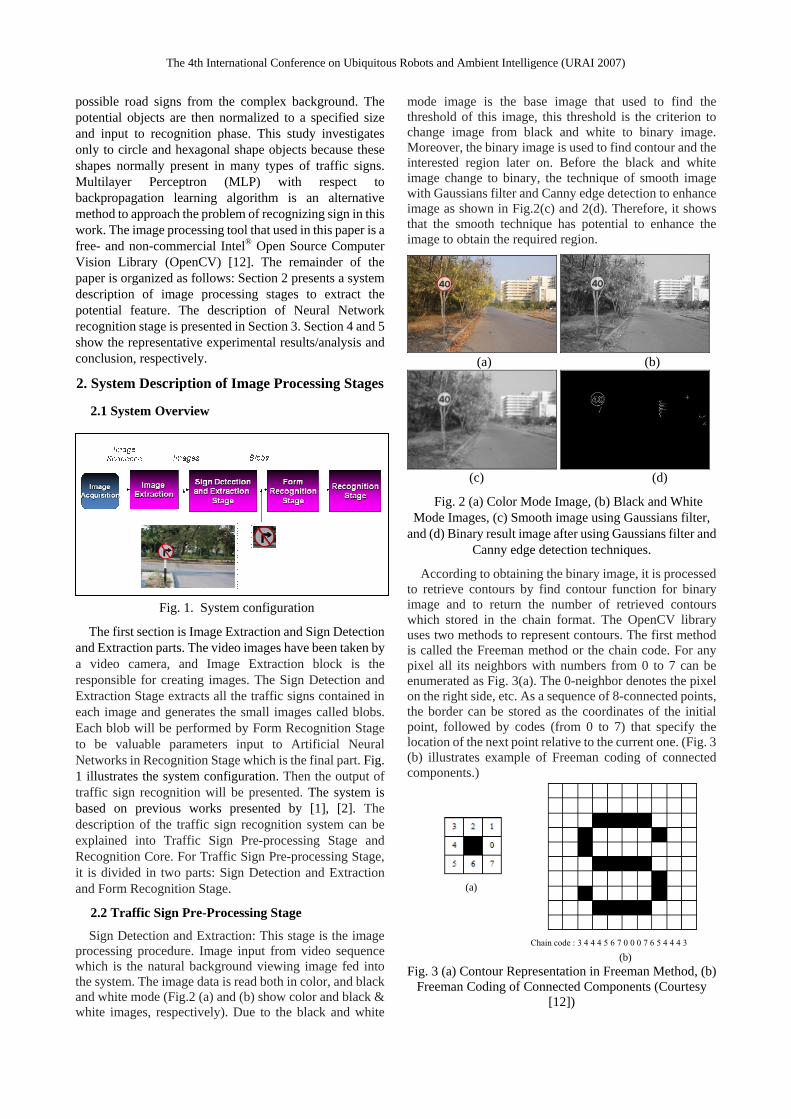
Sign Detection and Extraction: This stage is the image processing procedure. Image input from video sequence which is the natural background viewing image fed into the system. The image data is read both in color, and black and white mode (Fig.2 (a) and (b) show color and black & white images, respectively). Due to the black and white
mode image is the base image that used to find the threshold of this image, this threshold is the criterion to change image from black and white to binary image. Moreover, the binary image is used to find contour and the interested region later on. Before the black and white image change to binary, the technique of smooth image with Gaussians filter and Canny edge detection to enhance image as shown in Fig.2(c) and 2(d). Therefore, it shows that the smooth technique has potential to enhance the image to obtain the required region.
(a) (b)
(c) (d)
Fig. 2 (a) Color Mode Image, (b) Black and White Mode Images, (c) Smooth image using Gaussians filter,
and (d) Binary result image after using Gaussians filter and Canny edge detection techniques.
According to obtaining the binary image, it is processed to retrieve contours by find contour function for binary image and to return the number of retrieved contours which stored in the chain format. The OpenCV library uses two methods to represent contours. The first method is called the Freeman method or the chain code. For any pixel all its neighbors with numbers from 0 to 7 can be enumerated as Fig. 3(a). The 0-neighbor denotes the pixel on the right side, etc. As a sequence of 8-connected points, the border can be stored as the coordinates of the initial point, followed by codes (from 0 to 7) that specify the location of the next point relative to the current one. (Fig. 3 (b) illustrates example of Freeman coding of connected components.)
Chain code : 3 4 4 4 5 6 7 0 0 0 7 6 5 4 4 4 3
(b) Fig. 3 (a) Contour Representation in Freeman Method, (b)
Freeman Coding of Connected Components (Courtesy [12])
(a)
The 4th International Conference on Ubiquitous Robots and Ambient Intelligence (URAI 2007)
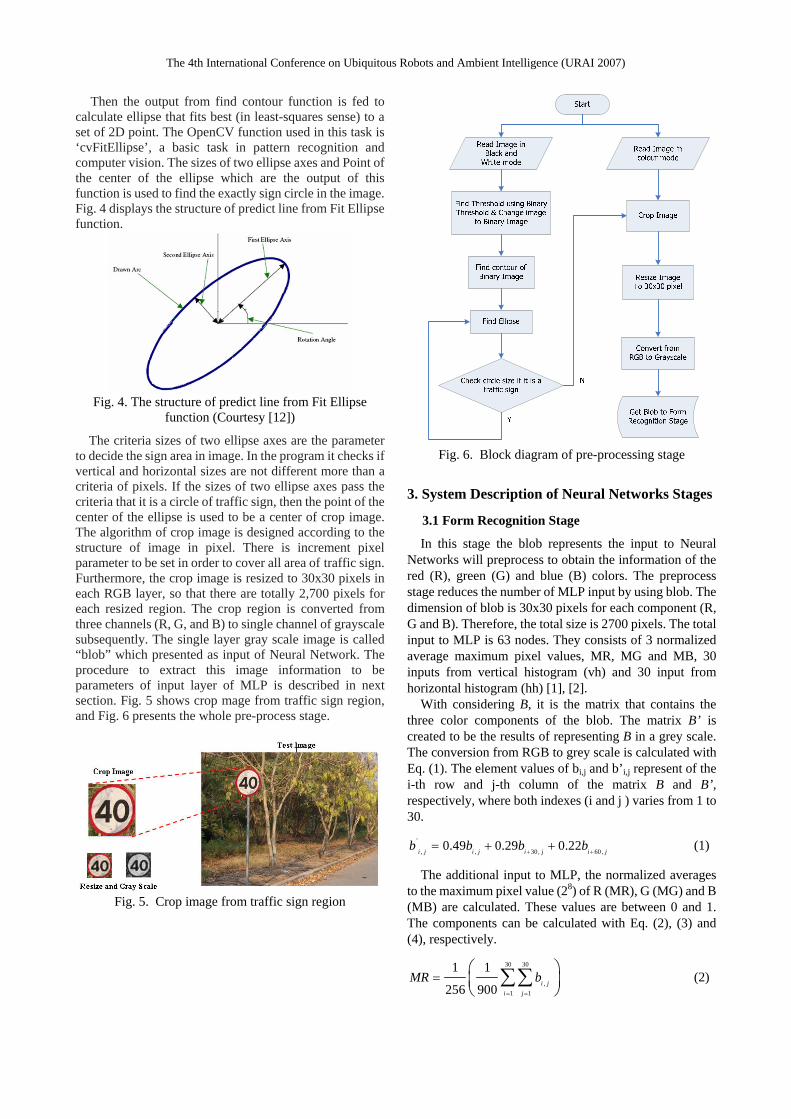
Then the output from find contour function is fed to
calculate ellipse that fits best (in least-squares sense) to a set of 2D point. The OpenCV function used in this task is ‘cvFitEllipse’, a basic task in pattern recognition and computer vision. The sizes of two ellipse axes and Point of the center of the ellipse which are the output of this function is used to find the exactly sign circle in the image. Fig. 4 displays the structure of predict line from Fit Ellipse function.
Fig. 4. The structure of predict line from Fit Ellipse
function (Courtesy [12])
The criteria sizes of two ellipse axes are the parameter to decide the sign area in image. In the program it checks if vertical and horizontal sizes are not different more than a criteria of pixels. If the sizes of two ellipse axes pass the criteria that it is a circle of traffic sign, then the point of the center of the ellipse is used to be a center of crop image. The algorithm of crop image is designed according to the structure of image in pixel. There is increment pixel parameter to be set in order to cover all area of traffic sign. Furthermore, the crop image is resized to 30x30 pixels in each RGB layer, so that there are totally 2,700 pixels for each resized region. The crop region is converted from three channels (R, G, and B) to single channel of grayscale subsequently. The single layer gray scale image is called “blob” which presented as input of Neural Network. The procedure to extract this image information to be parameters of input layer of MLP is described in next section. Fig. 5 shows crop mage from traffic sign region, and Fig. 6 presents the whole pre-process stage.
Fig. 5. Crop image from traffic sign region
Fig. 6. Block diagram of pre-processing stage
3. System Description of Neural Networks Stages
3.1 Form Recognition Stage
In this stage the blob represents the input to Neural Networks will preprocess to obtain the information of the red (R), green (G) and blue (B) colors. The preprocess stage reduces the number of MLP input by using blob. The dimension of blob is 30x30 pixels for each component (R, G and B). Therefore, the total size is 2700 pixels. The total input to MLP is 63 nodes. They consists of 3 normalized average maximum pixel values, MR, MG and MB, 30 inputs from vertical histogram (vh) and 30 input from horizontal histogram (hh) [1], [2].
With considering B, it is the matrix that contains the three color components of the blob. The matrix B’ is created to be the results of representing B in a grey scale. The conversion from RGB to grey scale is calculated with Eq. (1). The element values of bi,j and b’i,j represent of the i-th row and j-th column of the matrix B and B’, respectively, where both indexes (i and j ) varies from 1 to 30.
'
, , 30, 60,0.49 0.29 0.22i j i j i j i jb b b b+ +
= + + (1)
The additional input to MLP, the normalized averages to the maximum pixel value (28) of R (MR), G (MG) and B (MB) are calculated. These values are between 0 and 1. The components can be calculated with Eq. (2), (3) and (4), respectively.
30 30
,1 1
1 1
256 900 i ji j
MR b= =
=⎛ ⎞⎜ ⎟⎝ ⎠
∑∑ (2)
The 4th International Conference on Ubiquitous Robots and Ambient Intelligence (URAI 2007)
60 30
,31 1
1 1
256 900 i ji j
MG b= =
=⎛ ⎞⎜ ⎟⎝ ⎠
∑∑ (3)
90 30
,61 1
1 1
256 900 i ji j
MB b= =
=⎛ ⎞⎜ ⎟⎝ ⎠
∑∑ (4)
The 30 vertical parameters (vh) and 30 horizontal
parameters (hh) are calculated with Eq. (5) and (6), respectively.
30
,1
1( ' )
30i i jj
vh b T=
= >∑ , 1, 2,..., 30i = (5)
30
,1
1( ' )
30i i ji
vh b T=
= >∑ , 1, 2, ..., 30j = (6)
where 30 30
,1 1
1'
900 i ji j
T b= =
= ∑∑ , adaptive threshold.
3.2 Traffic Sign Data Base Description The data base has been divided into: train, validation
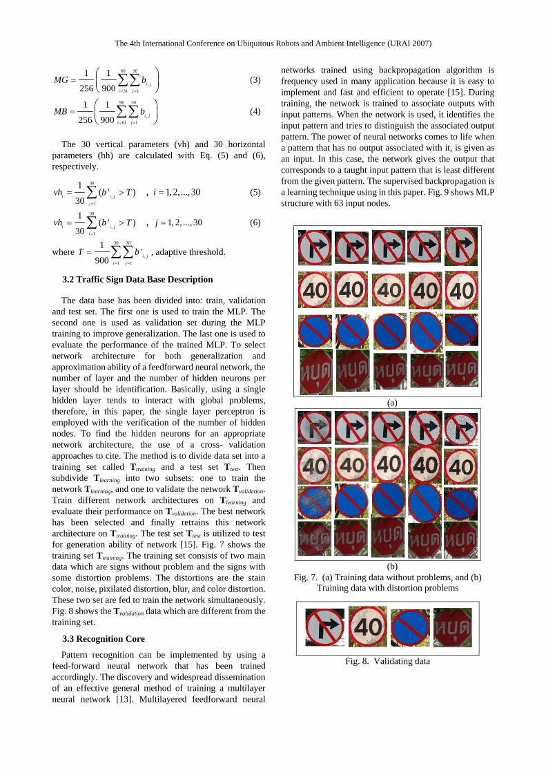
and test set. The first one is used to train the MLP. The second one is used as validation set during the MLP training to improve generalization. The last one is used to evaluate the performance of the trained MLP. To select network architecture for both generalization and approximation ability of a feedforward neural network, the number of layer and the number of hidden neurons per layer should be identification. Basically, using a single hidden layer tends to interact with global problems, therefore, in this paper, the single layer perceptron is employed with the verification of the number of hidden nodes. To find the hidden neurons for an appropriate network architecture, the use of a cross- validation approaches to cite. The method is to divide data set into a training set called Ttraining and a test set Ttest. Then subdivide Tlearning into two subsets: one to train the network Tlearning, and one to validate the network Tvalidation. Train different network architectures on Tlearning and evaluate their performance on Tvalidation. The best network has been selected and finally retrains this network architecture on Ttraining. The test set Ttest is utilized to test for generation ability of network [15]. Fig. 7 shows the training set Ttraining. The training set consists of two main data which are signs without problem and the signs with some distortion problems. The distortions are the stain color, noise, pixilated distortion, blur, and color distortion. These two set are fed to train the network simultaneously. Fig. 8 shows the Tvalidation data which are different from the training set.
3.3 Recognition Core
Pattern recognition can be implemented by using a feed-forward neural network that has been trained accordingly. The discovery and widespread dissemination of an effective general method of training a multilayer neural network [13]. Multilayered feedforward neural
networks trained using backpropagation algorithm is frequency used in many application because it is easy to implement and fast and efficient to operate [15]. During training, the network is trained to associate outputs with input patterns. When the network is used, it identifies the input pattern and tries to distinguish the associated output pattern. The power of neural networks comes to life when a pattern that has no output associated with it, is given as an input. In this case, the network gives the output that corresponds to a taught input pattern that is least different from the given pattern. The supervised backpropagation is a learning technique using in this paper. Fig. 9 shows MLP structure with 63 input nodes.
(a)
(b)
Fig. 7. (a) Training data without problems, and (b) Training data with distortion problems
Fig. 8. Validating data
The 4th International Conference on Ubiquitous Robots and Ambient Intelligence (URAI 2007)
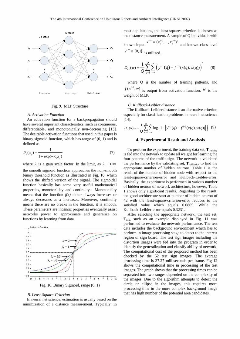
Fig. 9. MLP Structure
A. Activation Function An activation function for a backpropagation should
have several important characteristics, such as continuous, differentiable, and monotonically non-decreasing [13]. The desirable activation functions that used in this paper is binary sigmoid function, which has range of (0, 1) and is defined as
1( )
1 exp( )j j
j j
xx
δλ
=+ −
(7)
where iλ is a gain scale factor. In the limit, as iλ →∞ the smooth sigmoid function approaches the non-smooth binary threshold function as illustrated in Fig. 10, which shows the shifted version of the signal. The sigmoidal function basically has some very useful mathematical properties, monotonicity and continuity. Monotonicity means that the function f(x) either always increases or always decreases as x increases. Moreover, continuity means there are no breaks in the function, it is smooth. These parameters are intrinsic properties eventually assist networks power to approximate and generalize on functions by learning from data.
Fig. 10. Binary Sigmoid, range (0, 1)
B. Least-Square-Criterion In neural net science, estimation is usually based on the
minimization of a distance measurement. Typically, in
most applications, the least squares criterion is chosen as the distance measurement. A sample of Q individuals with
known input ( ) ( ) ( )
1( , ..., ) 'n n n
px x x= and known class level
( ) {0,1}ny ∈ is utilized.
( )2
( ) ( )
11( ) ( ( ), ( ))
1 ( )R
r r
LSr
Q
qD w y f x q w qq
Q ==
= −∑∑ (8)
where Q is the number of training patterns, and
( )( , )nf x w is output from activation function. w is the weight of MLP.
C. Kullback-Leibler distance The Kullback-Leibler distance is an alternative criterion
especially for classification problems in neural net science [14].
1
( ) ( )
1
( )1
log 1 ( ) ( ( ), ( ))R
KL
r
Qr r
q
D w y q f x q w qQ ==
= − − −⎡ ⎤⎣ ⎦∑∑ (9)
4. Experimental Result and Analysis
To perform the experiment, the training data set, Ttraining is fed into the network to update all weight for learning the four patterns of the traffic sign. The network is validated the performance by the validating set, Tvalidation to find the appropriate number of hidden neurons. Table 1 is the result of the number of hidden node with respect to the least-square-criterion-error and Kullback-Leibler-error. Basically, the experiment is performed in various number of hidden neuron of network architecture, however, Table 1 shows only significant results. Regarding to the result, the good architecture start at number of hidden neuron of 42 with the least-square-criterion-error reduces to the satisfied value which equals 0.0865. While the Kullback-Leibler-error equals 0.3231.
After selecting the appropriate network, the test set, Ttest, such as an example displayed in Fig. 11 was performed to evaluate the network performance. The test data includes the background environment which has to perform in image processing stage to detect to the interest region of sign board. The test sign images including the distortion images were fed into the program in order to identify the generalization and classify ability of network. The computational cost of the proposed method has been checked by the 52 test sign images. The average processing time is 37.27 milliseconds per frame. Fig 12 shows the computational time in processing of the test images. The graph shows that the processing times can be separated into two ranges depended on the complexity of the images. Due to the algorithm attempts to detect the circle or ellipse in the images, this requires more processing time in the more complex background image that has high number of the potential area candidates.
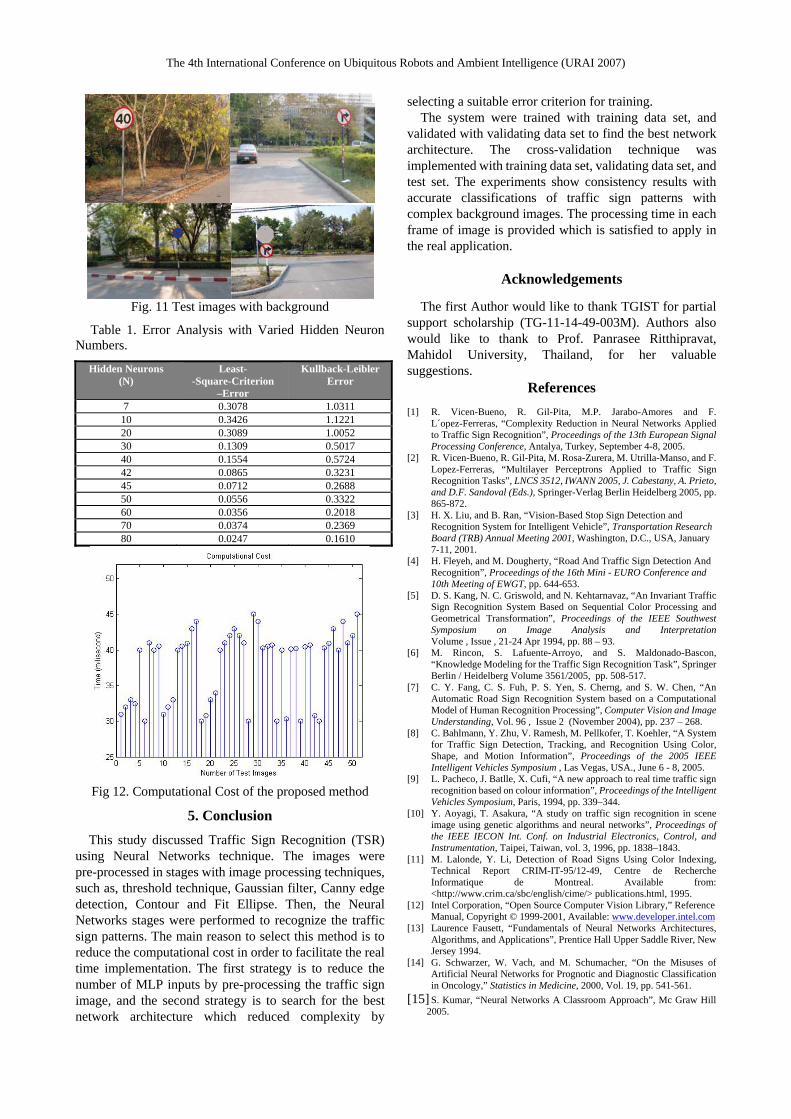
The 4th International Conference on Ubiquitous Robots and Ambient Intelligence (URAI 2007)
Fig. 11 Test images with background
Table 1. Error Analysis with Varied Hidden Neuron Numbers.
Hidden Neurons (N)
Least- -Square-Criterion
–Error
Kullback-Leibler Error
7 0.3078 1.0311 10 0.3426 1.1221 20 0.3089 1.0052 30 0.1309 0.5017 40 0.1554 0.5724 42 0.0865 0.3231 45 0.0712 0.2688 50 0.0556 0.3322 60 0.0356 0.2018 70 0.0374 0.2369 80 0.0247 0.1610
Fig 12. Computational Cost of the proposed method
5. Conclusion
This study discussed Traffic Sign Recognition (TSR) using Neural Networks technique. The images were pre-processed in stages with image processing techniques, such as, threshold technique, Gaussian filter, Canny edge detection, Contour and Fit Ellipse. Then, the Neural Networks stages were performed to recognize the traffic sign patterns. The main reason to select this method is to reduce the computational cost in order to facilitate the real time implementation. The first strategy is to reduce the number of MLP inputs by pre-processing the traffic sign image, and the second strategy is to search for the best network architecture which reduced complexity by
selecting a suitable error criterion for training. The system were trained with training data set, and
validated with validating data set to find the best network architecture. The cross-validation technique was implemented with training data set, validating data set, and test set. The experiments show consistency results with accurate classifications of traffic sign patterns with complex background images. The processing time in each frame of image is provided which is satisfied to apply in the real application.
Acknowledgements
The first Author would like to thank TGIST for partial
support scholarship (TG-11-14-49-003M). Authors also would like to thank to Prof. Panrasee Ritthipravat, Mahidol University, Thailand, for her valuable suggestions.
References [1] R. Vicen-Bueno, R. Gil-Pita, M.P. Jarabo-Amores and F.
L´opez-Ferreras, “Complexity Reduction in Neural Networks Applied to Traffic Sign Recognition”, Proceedings of the 13th European Signal Processing Conference, Antalya, Turkey, September 4-8, 2005.
[2] R. Vicen-Bueno, R. Gil-Pita, M. Rosa-Zurera, M. Utrilla-Manso, and F. Lopez-Ferreras, “Multilayer Perceptrons Applied to Traffic Sign Recognition Tasks”, LNCS 3512, IWANN 2005, J. Cabestany, A. Prieto, and D.F. Sandoval (Eds.), Springer-Verlag Berlin Heidelberg 2005, pp. 865-872.
[3] H. X. Liu, and B. Ran, “Vision-Based Stop Sign Detection and Recognition System for Intelligent Vehicle”, Transportation Research Board (TRB) Annual Meeting 2001, Washington, D.C., USA, January 7-11, 2001.
[4] H. Fleyeh, and M. Dougherty, “Road And Traffic Sign Detection And Recognition”, Proceedings of the 16th Mini - EURO Conference and 10th Meeting of EWGT, pp. 644-653.
[5] D. S. Kang, N. C. Griswold, and N. Kehtarnavaz, “An Invariant Traffic Sign Recognition System Based on Sequential Color Processing and Geometrical Transformation”, Proceedings of the IEEE Southwest Symposium on Image Analysis and Interpretation Volume , Issue , 21-24 Apr 1994, pp. 88 – 93.
[6] M. Rincon, S. Lafuente-Arroyo, and S. Maldonado-Bascon, “Knowledge Modeling for the Traffic Sign Recognition Task”, Springer Berlin / Heidelberg Volume 3561/2005, pp. 508-517.
[7] C. Y. Fang, C. S. Fuh, P. S. Yen, S. Cherng, and S. W. Chen, “An Automatic Road Sign Recognition System based on a Computational Model of Human Recognition Processing”, Computer Vision and Image Understanding, Vol. 96 , Issue 2 (November 2004), pp. 237 – 268.
[8] C. Bahlmann, Y. Zhu, V. Ramesh, M. Pellkofer, T. Koehler, “A System for Traffic Sign Detection, Tracking, and Recognition Using Color, Shape, and Motion Information”, Proceedings of the 2005 IEEE Intelligent Vehicles Symposium , Las Vegas, USA., June 6 - 8, 2005.
[9] L. Pacheco, J. Batlle, X. Cufi, “A new approach to real time traffic sign recognition based on colour information”, Proceedings of the Intelligent Vehicles Symposium, Paris, 1994, pp. 339–344.
[10] Y. Aoyagi, T. Asakura, “A study on traffic sign recognition in scene image using genetic algorithms and neural networks”, Proceedings of the IEEE IECON Int. Conf. on Industrial Electronics, Control, and Instrumentation, Taipei, Taiwan, vol. 3, 1996, pp. 1838–1843.
[11] M. Lalonde, Y. Li, Detection of Road Signs Using Color Indexing, Technical Report CRIM-IT-95/12-49, Centre de Recherche Informatique de Montreal. Available from: <http://www.crim.ca/sbc/english/cime/> publications.html, 1995.
[12] Intel Corporation, “Open Source Computer Vision Library,” Reference Manual, Copyright © 1999-2001, Available: www.developer.intel.com
[13] Laurence Fausett, “Fundamentals of Neural Networks Architectures, Algorithms, and Applications”, Prentice Hall Upper Saddle River, New Jersey 1994.
[14] G. Schwarzer, W. Vach, and M. Schumacher, “On the Misuses of Artificial Neural Networks for Prognotic and Diagnostic Classification in Oncology,” Statistics in Medicine, 2000, Vol. 19, pp. 541-561.
[15] S. Kumar, “Neural Networks A Classroom Approach”, Mc Graw Hill 2005.


![Workspace Determination and Robot Design of A Prototyped .... Jackrit's Papers/international proceedings/Workspace Determination...Endonasal transsphenoidal surgery [2]. Surgical Tool](https://static.fdocuments.us/doc/165x107/5e7d3f6dfc1005351034dbcd/workspace-determination-and-robot-design-of-a-prototyped-jackrits-papersinternational.jpg)

