Torsional vibration of a shafting system under electrical ...
12
Shock and Vibration 19 (2012) 1223–1233 1223 DOI 10.3233/SAV-2012-0666 IOS Press Torsional vibration of a shafting system under electrical disturbances Ling Xiang, Shixi Yang and Chunbiao Gan ∗ Department of Mechanical Engineering, Zhejiang University, Hangzhou, Zhejiang, China Received 24 May 2011 Accepted 14 November 2011 Abstract. Torsional vibration responses of a nonlinear shafting system are studied by a modified Riccati torsional transfer matrix combining with the Newmark-β method. Firstly, the system is modeled as a chain consisting of an elastic spring with concentrated mass points, from which a multi-segment lumped mass model is established. Secondly, accumulated errors are eliminated from the eigenfrequencies and responses of the system’s torsional vibration by this newly developed procedure. The incremental transfer matrix method, combining the modified Riccati torsional transfer matrix with Newmark-β method, is further applied to solve the dynamical equations for the torsional vibration of the nonlinear shafting system. Lastly, the shafting system of a turbine- generator is employed as an illustrating example, and simulation analysis has been performed on the transient responses of the shaft’s torsional vibrations during typical power network disturbances, such as three-phase short circuit, two-phase short circuit and asynchronous juxtaposition. The results validate the present method and are instructive for the design of a turbo-generator shaft. Keywords: Transfer matrix method, Newmark-β method, turbo-generator shaft, electrical disturbance, torsional vibration 1. Introduction Rotor dynamics plays an important role in many engineering fields, such as gas turbine, steam turbine, reciprocating and centrifugal compressors, the spindle of machine tools, and so on. Owing to the growing demands for high power of the rotor system, computations of critical speeds and dynamical response become essential for system design, identification, diagnosis, and control. Due to the turbine rotor failures at Southern California Edison’s Mohave station in 1970 and 1971 [1], industry’s attention was focused on the shaft’s torsional vibration caused by the transmission operation in a turbine-generator. The shafting system of modern large turbine-generator units is a high speed coaxial solid of revolution. It is connected by elastic-coupling parts, and composed of the turbine rotors, generator and exciter. An electromechanical transient process caused by power system failure or changes of operating conditions may lead to the shaft’s torsional vibration, which is very important for shafting system designers. Fundamental to the study of turbo-generator shaft torsional vibrations, as occurs in subsynchronous resonance and high speed reclosing, is the calculation of the characteristic frequencies and responses of the vibrations. Currently, the finite element and transfer matrix approaches are two of the most prevalent methods for analyzing torsional vibration of shafting systems. The finite element method (FEM) formulates rotor systems by second-order differential equations directly utilized for control design and estimation, while the transfer matrix method (TMM) solves dynamical problems in the frequency domain [2]. The TMM utilizes a marching procedure, i.e., starting with the boundary conditions at one side of the system and successively marching along the structure to the other side of the system. The satisfaction of the boundary conditions at all boundary points provides the basis for solution’s ∗ Corresponding author. E-mail: cb [email protected] or cb [email protected]. ISSN 1070-9622/12/$27.50 2012 – IOS Press and the authors. All rights reserved
Transcript of Torsional vibration of a shafting system under electrical ...
Shock and Vibration 19 (2012) 1223–1233 1223DOI 10.3233/SAV-2012-0666IOS Press
Torsional vibration of a shafting system underelectrical disturbances
Ling Xiang, Shixi Yang and Chunbiao Gan∗Department of Mechanical Engineering, Zhejiang University, Hangzhou, Zhejiang, China
Received 24 May 2011
Accepted 14 November 2011
Abstract. Torsional vibration responses of a nonlinear shafting system are studied by a modified Riccati torsional transfer matrixcombining with the Newmark-β method. Firstly, the system is modeled as a chain consisting of an elastic spring with concentratedmass points, from which a multi-segment lumped mass model is established. Secondly, accumulated errors are eliminated fromthe eigenfrequencies and responses of the system’s torsional vibration by this newly developed procedure. The incrementaltransfer matrix method, combining the modified Riccati torsional transfer matrix with Newmark-β method, is further applied tosolve the dynamical equations for the torsional vibration of the nonlinear shafting system. Lastly, the shafting system of a turbine-generator is employed as an illustrating example, and simulation analysis has been performed on the transient responses of theshaft’s torsional vibrations during typical power network disturbances, such as three-phase short circuit, two-phase short circuitand asynchronous juxtaposition. The results validate the present method and are instructive for the design of a turbo-generatorshaft.
Keywords: Transfer matrix method, Newmark-β method, turbo-generator shaft, electrical disturbance, torsional vibration
1. Introduction
Rotor dynamics plays an important role inmany engineeringfields,such as gas turbine, steam turbine, reciprocatingand centrifugal compressors, the spindle of machine tools, and so on. Owing to the growing demands for high powerof the rotor system, computations of critical speeds and dynamical response become essential for system design,identification, diagnosis, and control. Due to the turbine rotor failures at SouthernCalifornia Edison’sMohave stationin 1970 and 1971 [1], industry’s attention was focused on the shaft’s torsional vibration caused by the transmissionoperation in a turbine-generator. The shafting system of modern large turbine-generator units is a high speed coaxialsolid of revolution. It is connected by elastic-coupling parts, and composed of the turbine rotors, generator andexciter. An electromechanical transient process caused by power system failure or changes of operating conditionsmay lead to the shaft’s torsional vibration, which is very important for shafting system designers. Fundamental to thestudy of turbo-generator shaft torsional vibrations, as occurs in subsynchronous resonance and high speed reclosing,is the calculation of the characteristic frequencies and responses of the vibrations.
Currently, the finite element and transfer matrix approaches are two of the most prevalent methods for analyzingtorsional vibration of shafting systems. The finite element method (FEM) formulates rotor systems by second-orderdifferential equations directly utilized for control design and estimation, while the transfer matrix method (TMM)solves dynamical problems in the frequency domain [2]. The TMM utilizes a marching procedure, i.e., starting withthe boundary conditions at one side of the system and successively marching along the structure to the other sideof the system. The satisfaction of the boundary conditions at all boundary points provides the basis for solution’s
∗Corresponding author. E-mail: cb [email protected] or cb [email protected].
ISSN 1070-9622/12/$27.50 2012 – IOS Press and the authors. All rights reserved
1224 L. Xiang et al. / Torsional vibration of a shafting system under electrical disturbances
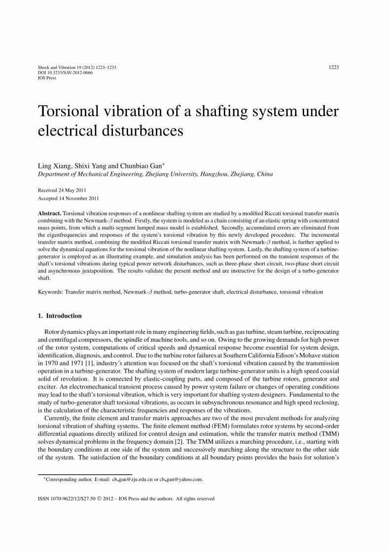
Fig. 1. Multi-segment lumped mass model.
location, and the state of the rotor system at a specific point is transferred between successive points through transfermatrices. This method is particularly suitable for “chainlinked” structures such as rotor systems, and primarily, itdoes not require the storage and manipulation of large system arrays [2].
The TMM was firstly proposed by Prohl [3]. Till now, there have been many contributions on the torsionalvibration characteristics [4–9]. Pestel and Leckie [10] provided a thorough reference for applying the TMM todetermine the natural frequencies and mode shapes for torsional systems. Rao [11] employed the TMM to analyzethe free vibration, transient response, critical speed, and instability of the torsional rotor system. In Ref. [12],Lee et al. improved the TMM of the continuous-systems to fit the synchronous elliptical orbits of the linear rotor-bearing systems by doubling the number of state variables. Their study also considered effects of the rotary inertia,gyroscopic and transverse shear. Furthermore, the TMM for continuous systems was extended to the unbalancingshaft [13] and the asymmetric rotor-bearing systems [14]. Aleyaasin et al. [15] applied the TMM to perform theflexural vibration analysis of a rotor mounted on fluid film bearings. Chen [16] investigated the torsional vibrationsof a cylinder with varying cross-section and adhesive masses. Koser and Pasin [17] discussed the torsional vibrationsof the drive shafts and mechanisms by means of analytical approach. In addition, the TMM and the Lagrangiandynamical method were developed to investigate the torsional and lateral vibrations of shafting systems in [18,19].
Customarily, there are two kinds of direct time-integration method to obtain the transient response of a dynamicalsystem. The first one is the explicit method such as the Runge-Kutta method, and the second one is the implicitmethod such as the Newmark method. Among the implicit methods, the Newmark method is based on the averageacceleration and used most widely, which can guarantee numerical stability and have the second-order accuracy [20].In Ref. [21], the Newmark-β method combining with the Newton-Raphson approach was used to solve the nonlineardifferential equations iteratively.
In this work, a modified Riccati torsional transfer matrix method is proposed. Combining with the Newmark-βmethod, it is applied to study the characteristic frequencies and responses of the torsional vibrations in the turbo-generator shaft during power network faults or disturbance. In Section 2, the shafting system is modeled as a chainconsisting of an elastic spring with concentrated mass points, and the modified Riccati transfer matrix method isthen employed to derive the equations of characteristic frequencies. In Section 3, the modified matrix method isfurther applied to solve the responses of the torsional vibration of shafts combining with the Newmark-β method.In Section 4, an experimental shafting system is set up to validate our approach. In the final section, the results ofthis work are summarized and discussed.
2. Modified riccati torsional transfer matrix
2.1. Shafting system model
According to the characteristic of a shaft’s structure, a shafting system can be discretized into n torsional vibrationunits, and the center line connecting all the units with large inertia is the center of the system. From Fig. 1, the shaftis now equivalent to a multi-segment lumped mass model. It consists of a uniform, free-free torsional bar with thelength L and torsional rigidity Ki, carrying n mass moment of inertia Ji (i = 1, 2, . . . n). The interest here lies inestablishing a relationship between the n eigenfrequencies of this torsional vibration system.
The equation of motion of the system shown in Fig. 1 can be written in the following classical form:
L. Xiang et al. / Torsional vibration of a shafting system under electrical disturbances 1225
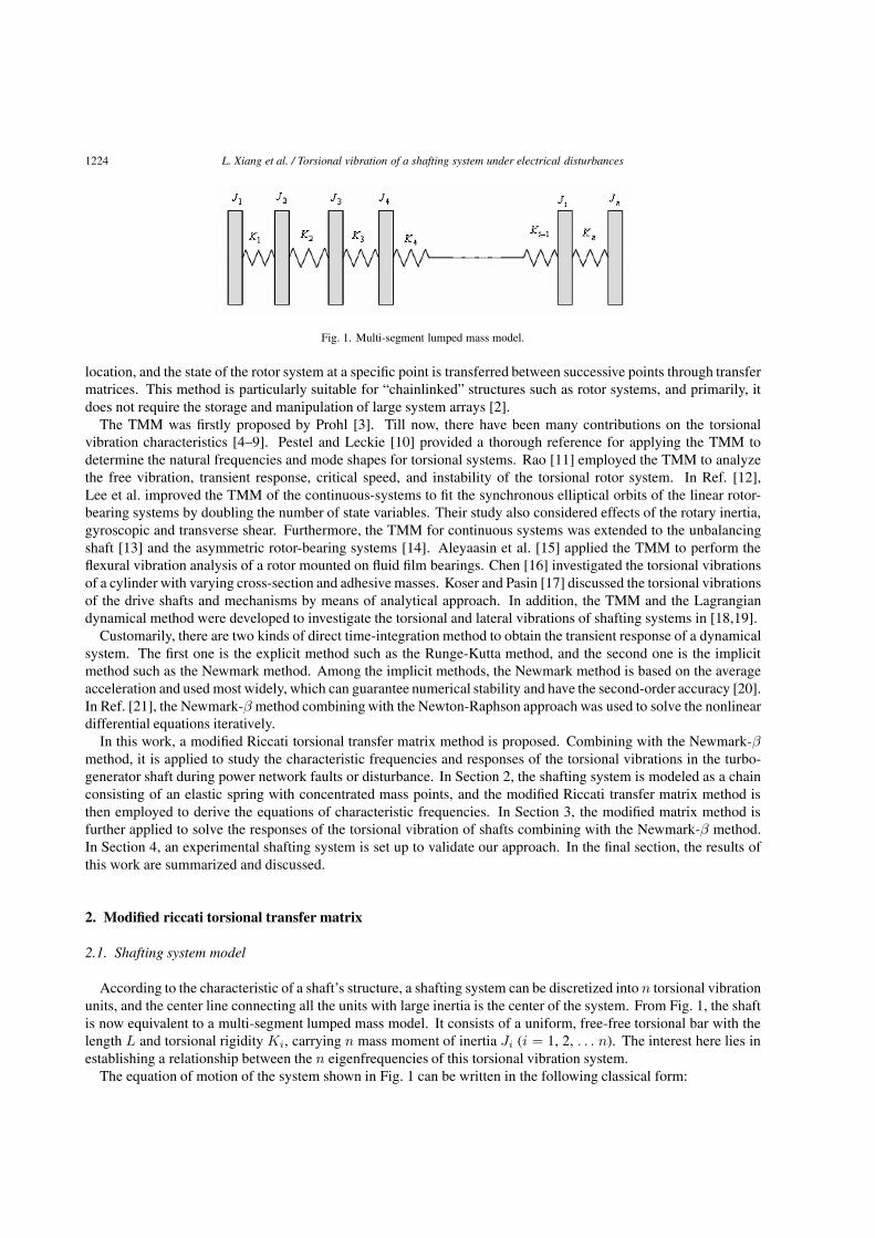
Fig. 2. Dynamical characteristic units.
Jθ̈(t) + Kθ(t) = Tt (1)
where Tt represents the external torque acting on the shaft, θ and θ̈ represent the rotational angular displacementand angular acceleration respectively, J and K represent the angular moment of inertia and the rigidity matrix,respectively. When the external torque Tt = 0, the natural frequencies and the mode shapes can be readily obtainedfrom the following equation:
Jθ̈(t) + Kθ(t) = 0 (2)
2.2. Riccati torsional transfer matrix
In Fig. 2, the system is further divided into a series of dynamical characteristic units. The state vector of theendpoint represents the torsional vibration state of the system, while the transfer matrix represents the relationshipbetween the state vectors of the adjacent elements.
The equation of motion of the i-th disk shown in Fig. 2 can be written as
Jiθ̈i = T Ri − T L
i (3)
where the state vector θi is the i-th torsional angular displacement, Ti is the i-th internal torsional torque, T Ri
represents the i-th internal torsional torque in the right side, and T Li represents the i-th internal torsional torque in
the left side. The relationship between the variables in the left and right sides has the following form[θT
]R
i
=[
1 0−ω2Ji 1
] [θT
]L
i
(4)
where
T Li = T R
i−1 (5)
and
θLi = θR
i−1 +Ti−1
Ki−1(6)
Substituting Eqs (5) and (6) into Eq. (4) yields[θT
]R
i
=
[1 1
Ki - 1−p2Ji 1 − p2Ji
Ki−1
][θT
]R
i−1
(7)
where p is the angular frequency. When we introduce the Riccati transfer matrix [S]i: {f}Ri = [S]i {e}R
i ,
{Z}i ={
ef
}R
i
, {e}i = θi, {f}i = Ti, Eq. (7) is then replaced by
[ef
]R
i+1
=[
U11 U12
U21 U22
]i
[ef
]R
i
(8)
1226 L. Xiang et al. / Torsional vibration of a shafting system under electrical disturbances
[S]i+1 ={f}R
i+1
{e}Ri+1
=U21i + U22i [S]iU11i + U12i [S]i
(9)
Equation (9) is the recurrence relation equationwhich can be used to calculate the natural frequency of the torsionalvibration for a shafting system. With a certain calculating step, there must be a zero point between the residualvalues for the trial frequencies if the signs of two residual values are different, that is to say, there exits a correct rootof the frequency equation between the two trial frequencies, which could be obtained from differential calculation.When the natural frequency is confirmed, its corresponding mode shape can also be deduced from Eq. (7).
2.3. Improved riccati torsional transfer matrix
In the use of Riccati method, the frequency equation usually leads to infinite singular points owing to the divisionoperation, which influence the effectual calculation of the natural frequency. For the sake of eliminating the infinitesingular points, Eq. (9) is improved by
R = [S]i+1 ·N∏
i=1
U11i + U12i[S]iabs(U11i + U12i[S]i)
= 0 (10)
where N is the total number of characteristic units (see Figs 1 and 2), the symbol “Π” denotes the multiply operator,and “abs(x)”means the absolute value of “x”. The improvedcharacteristic Eq. (10) can not only retain the advantagesof the classical transfer matrix, but also avoid to lose the intrinsic frequency or add any nonexistent frequency dueto the interference of infinite singular points.
3. Incremental transfer matrix method
3.1. Incremental equation
Rotor system is a highly complex nonlinear vibration system. For such a system, classical vibration theoriesand perturbation methods are no longer applicable. Currently, there are two categories of methods to calculate thetransient vibration response of a rotor, i.e., the TMM and the mode synthesis method, both are supplemented bynumerical integration. However, they can not be directly applied to study the torsional vibration of a rotor system.
In this subsection, we combine the Newmark-β method with the TMM to establish the incremental equations ofthe rotor system. The Newmark-β method is an integration method, and can be used to solve nonlinear equationseffectively. The iteration algorithm from this method is usually expressed by the acceleration and velocity as
q̈t+Δt =1
βΔt2(qt+Δt − qt) − 1
βΔtq̇t −
(12β
− 1)
q̈t (11)
q̇t+Δt = q̇t +γ
βΔt(qt+Δt − qt) − γ
βq̇t −
(γ
2β− 1
)q̈tΔt (12)
where γ and β are the parameters of the Newmark-β function, q is the generalized coordinate. From Eqs (11)–(12),the incremental equations are written as
Δq̈t+Δt = q̈t+Δt − q̈t =1
βΔt2(Δqt+Δt) − 1
βΔtq̇t −
(12β
)q̈t (13)
Δq̇t+Δt = q̇t+Δt − q̇t =γ
βΔt(Δqt+Δt) − γ
βq̇t −
(γ
2β− 1
)q̈tΔt (14)
Now, Eqs (13)–(14) describe the incremental changes of the velocity and acceleration during the given timeinterval Δt, and can be applied to solve nonlinear equations.
L. Xiang et al. / Torsional vibration of a shafting system under electrical disturbances 1227
3.2. Incremental transfer equations of torsional vibration
From Fig. 1, the typical shafting system can be modeled as multi-disks. Each disk is acted by the inertia torque,the resistance torque, the torques from the left and right cross-sections, and the external torque. According to themoment equilibrium condition, the incremental equation is expressed as
ΔT Ri (t + Δt) = ΔT L
i (t + Δt) + JiΔθ̈ (t + Δt) + CiΔθ̇ (t + Δt) − ΔTti (t + Δt) (15)
where ΔθRi = ΔθL
i , Ci is the resistance coefficient, and ΔTti is the inertia torque.Substituting Eqs (13)–(14) into (15) yields
ΔT Ri = ΔT L
i + Ai · ΔθLi + Bi (16)
where
Ai =Ji
β · Δt2+
Ciγ
β · Δt, Bi = −Ji
(1
β · Δt· θ̈i +
12β
· θ̈i
)− Ci
[γ
β· θ̇i +
(γ
2β− 1
)· θ̈iΔt
](17)
−ΔTti (t + Δt)
For massless elastic shaft section, the incremental relation is as follows{ΔT R
i = ΔT Li+1
ΔθLi+1 = ΔθR
i + ΔT Ri
Ki
(18)
In respect to Eq. (8), for the i-th disk, if we denote fi ≡ ΔTi and ei ≡ Δθi, then the transfer matrix can be writtenas {
fe
}L
i+1
=[
U11 U12
U21 U22
]{fe
}L
i
+{
Ff
Fe
}i
(19)
where U11 = 1, U12 = Ai, U21 = 1/Ki, U22 = 1 + Ai/Ki, Ffi = Bi, Fei = Bi/Ki.Substituting the Riccati transfer relation fL
i = SieLi + Pi into Eq. (19), we have⎧⎨
⎩Si+1 = [U11iSi + U12i] · [U21iSi + U22i]
−1
Pi+1 = [U11iPi + Ffi] − Si+1 [U21iPi + Fei]eL
i = [U21iSi + U22i]−1 eL
i+1 − [U21iSi + U22i]−1 [U21iPi + Fei]
(20)
Then, the transfer matrices of Si, Pi and eLi can be derived from Eq. (20).
4. An illustrating example
4.1. Natural frequencies of torsional vibration
Figure 3 shows the shafting system of a turbo-generator, where the length unit is mm. This physical shaftingsystem can adopt the rotor structure to simulate the high-pressure cylinder rotor, the low pressure cylinder rotor, thegenerator rotor, and the main exciter rotor. This simulated shaft is a multiple-rotor spring-mass system as shown inFig. 1. Here, the total number of characteristic units is n = 163.
The torsional natural frequencies of the shafting system are calculated throughEq. (9), where the shafting system isassumed to be free-free for the torsional vibration, and the boundary conditions on the start section are {e}1 = θ1 �= 0and {f}1 = T1 = 0, while those on end section are {e}n = θn �= 0 and {f}n = Tn = 0. So, we have
[S]1 = {f}1{e}1
= 0 and [S]n = {f}n
{e}n= 0.
The first five natural frequencies for the torsional vibration of the shaft are shown in Table 1, where the frequenciesby Eq. (9) are consistent with the design values. So, the improved Riccati transfer matrix method is very effective.In Fig. 4, we present the mode shapes corresponding to the first three natural frequencies.

1228 L. Xiang et al. / Torsional vibration of a shafting system under electrical disturbances
Table 1The natural frequencies of the torsional vibration for the shaft
Order 1 2 3 4 5
Calculation (Hz) 7.05 26.08 41.23 47.31 72.08Design Value (Hz) 7.35 25.75 40.55 46.75 71.75
Fig. 3. The shaft structure of a turbo-generator, length unit: mm.
Fig. 4. The first three natural torsional modes of the shaft.
4.2. Responses of torsional vibration under electrical disturbances
To calculate the responses of the torsional vibration of the shaft, we firstly establish the physical parametersJi, Ci, Ki, and the external torque incrementΔTti as shown in Fig. 1. For the sake of abbreviation, these parameters’values are not presented here. For the free-free shaft, the boundary conditions for the left and the right sectionsare fL
1 = 0, eL1 �= 0, S1 = 0, P1 = 0 and fR
n = fLn + AneL
n + Bn = 0 respectively, where fLn = SneL
n + Pn,eL
n = − (Pn + Bn) / (Sn + An). Substituting the boundary conditions into Eq. (19), we can obtain the angulardisplacement increment eL
i (i = n, n − 1, · · · , 1) of each node and the torque increment fLi of each section from
right to left at the instant t + Δt by the recursive formula.In general, the short-circuit fault can bring a strong impact on the short-circuit current and the torque in the vicinity
of a power system, especially in the generator outlet. The electromagnetic torque of two-phase and three-phaseshort-circuit can be described as in Ref. [21]. Equation (21) is the electromagnetic torque for three-phase short-circuit, its characteristic in time-domain is displayed in Fig. 5(a). While Eq. (22) is the electromagnetic torque fortwo-phase short-circuit, its characteristic in time-domain is displayed in Fig. 5(b).

L. Xiang et al. / Torsional vibration of a shafting system under electrical disturbances 1229
Fig. 5. Characteristics of the electromagnetic torques under the short-circuit faults.
Fig. 6. Characteristics of the electromagnetic torques under the asynchronous juxtapositions.
Tt(x, t) = M0(AMe−αt sin ωt + BM2) (21)
where A = 6.259, B = 0.0877, α = 3.9809, ω = 2πn1/60, M0 is the rated torque of the generator under the normaloperation, M = 0.07954 + 0.563e−1.1443t + 0.3569e−9.1575t, and n1 is the speed of the rotor, see [21]. So,
Tt(x, t) = M0(Ae−αt sin ωt − Be−βt sin 2ωt + Ce−γt) (22)
where A = 7.591, B = 3.795, C = 0.742, α = 5.305, β = 2.65, γ = 4.428, and the other parameters are the sameas those in Eq. (21).
The asynchronous juxtaposition with a strong impact on the current and the torque is one of the typical electricalinterferences during the power operation. The electromagnetic torques of 120◦ and 180◦ asynchronous juxtapositionscan be described as Eqs (23)–(24), where Eq. (23) is the electromagnetic torque for 120◦ asynchronous juxtaposition,its characteristic in time-domain is displayed in Fig. 6(a), while Eq. (24) is the electromagnetic torque for 180◦
asynchronous juxtaposition, its characteristic is displayed in Fig. 6(b).
Tt (x, t) = M0 (M1 (t) · M2 (t) + M3 (t)) (23)
where M1 (t) = 2.796 × (0.2226e−7.5175t + 0.634e−0.876t + 0.7774
), M2 (t) = e−9.1575t cosωt, M3 (t) =
5.004 sinωt − 2.796e−3.981t cosωt. So,
Tt(x, t) = M0Ae−αt sin ωt (24)
where A = 6.6172, α = 3.9809, and the other parameters are the same as those in Eq. (21).In a variety of short-circuit faults, the two-phase or three-phase short-circuit of the generator outlet is more serious
for the shaft. The electromagnetic torque of the two-phase short-circuit shown in Fig. 6(b) is larger than that of thethree-phase short-circuit shown in Fig. 6(a). Figures 7 and 8 are the dynamical responses and their correspondingfrequencies of the torsional vibration under the network short circuit faults. The response trail of the torsionalvibration under the two-phase short-circuit in Fig. 8(a) is similar to that under the three-phase short-circuit in Fig. 7(a),and the fast Fourier transform (FFT) plots shown in Figs 7(b) and 8(b) indicate that both the responses have thesame frequencies, i.e., 7.0 Hz, 26.2 Hz, 41.4 Hz, 47.6 Hz, 50 Hz and 72.1 Hz, among which the frequency 50 Hz
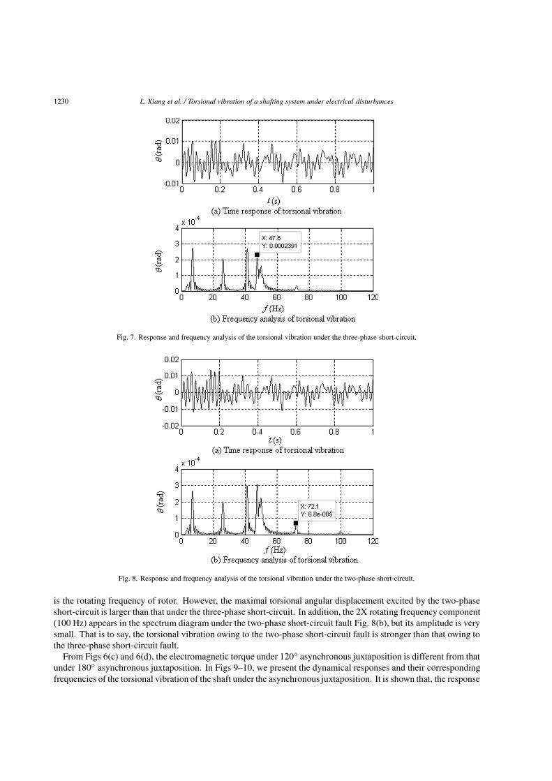
1230 L. Xiang et al. / Torsional vibration of a shafting system under electrical disturbances
Fig. 7. Response and frequency analysis of the torsional vibration under the three-phase short-circuit.
Fig. 8. Response and frequency analysis of the torsional vibration under the two-phase short-circuit.
is the rotating frequency of rotor. However, the maximal torsional angular displacement excited by the two-phaseshort-circuit is larger than that under the three-phase short-circuit. In addition, the 2X rotating frequency component(100 Hz) appears in the spectrum diagram under the two-phase short-circuit fault Fig. 8(b), but its amplitude is verysmall. That is to say, the torsional vibration owing to the two-phase short-circuit fault is stronger than that owing tothe three-phase short-circuit fault.
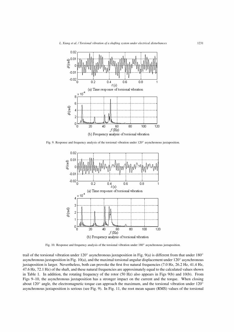
From Figs 6(c) and 6(d), the electromagnetic torque under 120◦ asynchronous juxtaposition is different from thatunder 180◦ asynchronous juxtaposition. In Figs 9–10, we present the dynamical responses and their correspondingfrequencies of the torsional vibration of the shaft under the asynchronous juxtaposition. It is shown that, the response
L. Xiang et al. / Torsional vibration of a shafting system under electrical disturbances 1231
Fig. 9. Response and frequency analysis of the torsional vibration under 120◦ asynchronous juxtaposition.
Fig. 10. Response and frequency analysis of the torsional vibration under 180◦ asynchronous juxtaposition.
trail of the torsional vibration under 120◦ asynchronous juxtaposition in Fig. 9(a) is different from that under 180◦
asynchronous juxtaposition in Fig. 10(a), and the maximal torsional angular displacement under 120◦ asynchronousjuxtaposition is larger. Nevertheless, both can provoke the first five natural frequencies (7.0 Hz, 26.2 Hz, 41.4 Hz,47.6 Hz, 72.1 Hz) of the shaft, and these natural frequencies are approximately equal to the calculated values shownin Table 1. In addition, the rotating frequency of the rotor (50 Hz) also appears in Figs 9(b) and 10(b). FromFigs 9–10, the asynchronous juxtaposition has a stronger impact on the current and the torque. When closingabout 120◦ angle, the electromagnetic torque can approach the maximum, and the torsional vibration under 120◦
asynchronous juxtaposition is serious (see Fig. 9). In Fig. 11, the root mean square (RMS) values of the torsional
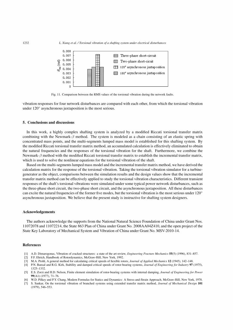
1232 L. Xiang et al. / Torsional vibration of a shafting system under electrical disturbances
Fig. 11. Comparison between the RMS values of the torsional vibration during the network faults.
vibration responses for four network disturbances are compared with each other, from which the torsional vibrationunder 120◦ asynchronous juxtaposition is the most serious.
5. Conclusions and discussions
In this work, a highly complex shafting system is analyzed by a modified Riccati torsional transfer matrixcombining with the Newmark-β method. The system is modeled as a chain consisting of an elastic spring withconcentrated mass points, and the multi-segments lumped mass model is established for this shafting system. Bythe modified Riccati torsional transfer matrix method, an accumulated calculation is effectively eliminated to obtainthe natural frequencies and the responses of the torsional vibration for the shaft. Furthermore, we combine theNewmark-β method with the modified Riccati torsional transfer matrix to establish the incremental transfer matrix,which is used to solve the nonlinear equations for the torsional vibration of the shaft.
Based on the multi-segments lumped mass model and the incremental transfer matrix method, we have derived thecalculation matrix for the response of the torsional vibration. Taking the torsional vibration simulator for a turbine-generator as the object, comparisons between the simulation results and the design values show that the incrementaltransfer matrix method can be effectively applied to study the torsional vibration characteristics. Different transientresponses of the shaft’s torsional vibrations were simulated under some typical power network disturbances, such asthe three-phase short circuit, the two-phase short circuit, and the asynchronous juxtaposition. All these disturbancescan excite the natural frequencies of the former five modes, but the torsional vibration is the most serious under 120◦
asynchronous juxtaposition. We believe that the present study is instructive for shafting system designers.
Acknowledgements
The authors acknowledge the supports from the National Natural Science Foundation of China under Grant Nos.11072078 and 11072214, the State 863 Plan of China under Grant No. 2008AA04Z410, and the open project of theState Key Laboratory of Mechanical System and Vibration of China under Grant No. MSV-2010-14.
References
[1] A.D. Dimarogonas, Vibration of cracked structures: a state of the art review, Engineering Fracture Mechanics 55(5) (1996), 831–857.[2] F.F. Ehrich, Handbook of Rotordynamics, McGraw-Hill, New York, 1992.[3] M.A. Prohl, A general method for calculating critical speeds of fiexible rotors, Journal of Applied Mechanics 12 (1945), 142–148.[4] P.N. Bansal and R.G. Kirk, Stability and damped critical speeds of rotor-bearing systems, Journal of Engineering for Industry 97 (1975),
1325–1332.[5] E.S. Zorzi and H.D. Nelson, Finite element simulation of rotor-bearing systems with internal damping, Journal of Engineering for Power
99(A1) (1977), 71–76.[6] W.D. Pilkey and P.Y. Chang, Modern Formulas for Statics and Dynamics: A Stress-and-Strain Approach, McGraw-Hill, New York, 1978.[7] S. Sankar, On the torsional vibration of branched systems using extended transfer matrix method, Journal of Mechanical Design 101
(1979), 546–553.
L. Xiang et al. / Torsional vibration of a shafting system under electrical disturbances 1233
[8] J.W. Lund, Sensitivity of the critical speeds of a rotor to changes in the design, Journal of Mechanical Design 102 (1980), 115–121.[9] K.B. Yim, S.T. Noah and J.M. Vance, Effect of tangential torque on the dynamics of fiexible rotors, Journal of Applied Mechanics 53
(1986), 711–718.[10] E.C. Pestel and F.A. Leckie, Matrix Methods in Elastomechanics, McGraw-Hill, New York, 1963.[11] J.S. Rao, Rotor Dynamics, Wiley Eastern, New Delhi, 1991.[12] A.C. Lee, Y. Kang and S.L. Liu, A modified transfer matrix method for linear rotor-bearing systems, Journal of Applied Mechanics 58
(1991), 776–783.[13] A.C. Lee, Y.P. Shih and Y. Kang, The analysis of linear rotor-bearing systems: a general transfer matrix method, Journal of Vibration and
Acoustics 115 (1993), 490–496.[14] S.C. Hsieh, J.H. Chen and A.C. Lee, A modified transfer matrix method for the coupled lateral and torsional vibrations of asymmetric
rotor-bearing systems, Journal of Sound and Vibration 312 (2008), 563–571.[15] M. Aleyaasin, M. Ebrahimi and R. Whalley, Multivariable hybrid models for rotor-bearing systems, Journal of Sound and Vibration 233
(2000), 835–856.[16] Y.Z. Chen, Torsional free vibration of a cylinder with varying cross-section and adhesive masses, Journal of Sound and Vibration 241(3)
(2001), 503–512.[17] K. Koser and F. Pasin, Torsional vibrations of the drive shafts of mechanisms, Journal of Sound and Vibration 199 (1997), 559–565.[18] J.S. Wu and I.H. Yang, Computer method for torsion-and-fiexural-coupled forced vibration of shafting system with damping, Journal of
Sound and Vibration 180(3) (1995), 417–435.[19] B.O. Al-Bedoor, Transient torsional and lateral vibrations of unbalanced rotors with rotor-to-stator rubbing, Journal of Sound and Vibration
229 (2000), 627–645.[20] S.P. Harsha and P.K. Kankar, Stability analysis of a rotor bearing system due to surface waviness and number of balls, Journal of Mechanical
Sciences 46 (2004), 1057–1081.[21] K. Bathe and E. Wilson, Numerical methods in finite element analysis. Englewood Cliffs, NJ: Prentice-Hall, 1990.[22] IEEE SSR Working Group. Second benchmark model for computer simulation of subsynchronous oscillations, IEEE Trans on PAS 104(5)
(1985), 1057–1066.

International Journal of
AerospaceEngineeringHindawi Publishing Corporationhttp://www.hindawi.com Volume 2010
RoboticsJournal of
Hindawi Publishing Corporationhttp://www.hindawi.com Volume 2014
Hindawi Publishing Corporationhttp://www.hindawi.com Volume 2014
Active and Passive Electronic Components
Control Scienceand Engineering
Journal of
Hindawi Publishing Corporationhttp://www.hindawi.com Volume 2014
International Journal of
RotatingMachinery
Hindawi Publishing Corporationhttp://www.hindawi.com Volume 2014
Hindawi Publishing Corporation http://www.hindawi.com
Journal ofEngineeringVolume 2014
Submit your manuscripts athttp://www.hindawi.com
VLSI Design
Hindawi Publishing Corporationhttp://www.hindawi.com Volume 2014
Hindawi Publishing Corporationhttp://www.hindawi.com Volume 2014
Shock and Vibration
Hindawi Publishing Corporationhttp://www.hindawi.com Volume 2014
Civil EngineeringAdvances in
Acoustics and VibrationAdvances in
Hindawi Publishing Corporationhttp://www.hindawi.com Volume 2014
Hindawi Publishing Corporationhttp://www.hindawi.com Volume 2014
Electrical and Computer Engineering
Journal of
Advances inOptoElectronics
Hindawi Publishing Corporation http://www.hindawi.com
Volume 2014
The Scientific World JournalHindawi Publishing Corporation http://www.hindawi.com Volume 2014
SensorsJournal of
Hindawi Publishing Corporationhttp://www.hindawi.com Volume 2014
Modelling & Simulation in EngineeringHindawi Publishing Corporation http://www.hindawi.com Volume 2014
Hindawi Publishing Corporationhttp://www.hindawi.com Volume 2014
Chemical EngineeringInternational Journal of Antennas and
Propagation
International Journal of
Hindawi Publishing Corporationhttp://www.hindawi.com Volume 2014
Hindawi Publishing Corporationhttp://www.hindawi.com Volume 2014
Navigation and Observation
International Journal of
Hindawi Publishing Corporationhttp://www.hindawi.com Volume 2014
DistributedSensor Networks
International Journal of