Torit Radial Blade Fan - Donaldson Company · Torit Radial Blade Fan, TRB-1 through 10 2...
20
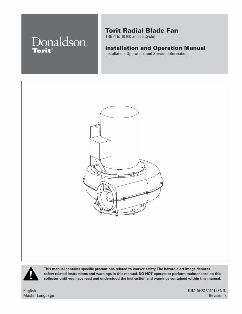
This manual contains specific precautions related to worker safety. The hazard alert image denotes safety related instructions and warnings in this manual. DO NOT operate or perform maintenance on this collector until you have read and understood the instruction and warnings contained within this manual. Torit Radial Blade Fan TRB-1 to 10 (60 and 50 Cycle) Installation and Operation Manual Installation, Operation, and Service Information IOM AG8130401 (ENG) Revision 2 English Master Language
Transcript of Torit Radial Blade Fan - Donaldson Company · Torit Radial Blade Fan, TRB-1 through 10 2...
This manual contains specific precautions related to worker safety. The hazard alert image denotes safety related instructions and warnings in this manual. DO NOT operate or perform maintenance on this collector until you have read and understood the instruction and warnings contained within this manual.
Torit Radial Blade Fan TRB-1 to 10 (60 and 50 Cycle)
Installation and Operation ManualInstallation, Operation, and Service Information
IOM AG8130401 (ENG)Revision 2
English Master Language
Donaldson Company, Inc.
i
The Safety Alert Symbol indicates a hazardous situation which, if not avoided could result in death or serious injury. Obey all safety messages following this symbol to avoid possible injury or death. The possible hazards are explained in the associated text messages.
CAUTION, used with the safety alert symbol, indicates a hazardous situation which, if not avoided, could result in minor or moderate injury.NOTICE indicates a potential situation or practice which is not expected to result in personal injury, but which if not avoided, may result in damage to equipment.
This manual has been supplied to assist with the installation, operation and maintenance for the collector purchased. Please read the manual before installing, operating, or performing maintenance on the collector as it contains specific precautions for worker safety. It is the owner’s responsibility to ensure that this manual is available for use by installers, operators and maintenance personnel that will be working with this collector. This manual is the property of the owner and should be left with the collector when installation has been completed. DO NOT operate this collector until you have read and understood the instructions and warnings located in the installation and operation manual.
For additional copies of this manual, contact Donaldson Torit
IMPORTANT NOTES
Torit Radial Blade Fan, TRB-1 through 10
ii
Contents
IMPORTANT NOTES .................................................................iSafety Communication ............................................................1Description ................................................................................2Operation ...................................................................................2Inspection on Arrival ...............................................................2Installation Codes and Procedures ......................................2
Hoisting Information ............................................................3Storage ...................................................................................3Electrical Wiring ...................................................................3
Fan Installation .........................................................................4Motor Drain Hole Orientation (Side Mount Fans) ................................................................6Top Mount Fan Blower Installation Instructions .............6
Initial Fan Start-Up ...................................................................7Duct Connections and Support ..........................................8Top Mount Chamber Silencer ............................................8
Maintenance Information .......................................................9Motor Maintenance .............................................................9Grease Motors ....................................................................10Wheel Balance ...................................................................10
Troubleshooting Guidelines ..................................................10Troubleshooting ......................................................................11Product Information...............................................................13Service Notes .........................................................................14Donaldson Industrial Air Filtration Warranty ....................16
1
Donaldson Company, Inc.
Improper operation of dust collectors and/or dust control systems may contribute to conditions in a work area or facility which could result in severe personal injury, and product or property damage. All dust collection equipment should be used only for its intended purpose and should be properly selected and sized for its intended use.Process owners have important responsibilities relating to identifying and addressing potential hazards in their processes. When the potential for handling combustible dust exists within a process the process owner should include combustion hazards in their risk management activities and should comply with applicable codes and standards related to combustible dust.Electrical installation must be performed by a qualified electrician.This equipment is not designed to support site ducts, piping, or electrical services. All ducts, piping, or electrical services must be adequately supported to prevent injury and/or property damage.Site selection must account for wind, seismic zone, and other load conditions.Equipment may reach peak sound pressure levels above 80 dB (A). Noise levels should be considered when selecting collector location.
Combustible Dust Hazards
Among other considerations, the current NFPA standards require owners whose processes involve potentially combustible materials to have a current Dust Hazard Analysis, which can serve as the foundation for their process hazard mitigation strategy. Mitigation may include but is not limited to:
• Prevention of all ignition sources from entering any dust collection equipment.
• Selection and implementation of fire and explosion mitigation, suppression, and isolation strategies appropriate for the risks in their process.
• Development and use of work practices to maintain safe operating conditions, and to ensure combustible dust does not accumulate within their plant or process equipment.
Donaldson designs, manufactures, and sells industrial air filtration products for a wide variety of applications. Some applications may include processes or materials with inherent fire and explosion hazards. Donaldson is neither an expert nor a certified consultant in fire, spark, or explosion detection, suppression, or control. Donaldson does not provide engineering consulting services related to process or dust hazard analyses, or code and standard compliance. Complying with applicable codes and standards and managing the risks associated with the process or materials remains the responsibility of the process owner/operator. Donaldson may provide referrals to consultants, suppliers of equipment or services related to the detection and/or mitigation of sparks, fires and/or explosions, but Donaldson does not assume responsibility for any such referrals, nor does Donaldson assume any liability for the fitness of a mitigation strategy or product for a particular installation or application. The process owner’s final selection of dust collectors and risk mitigation strategies should be based on the outcome of a Dust Hazard / Process Hazard Analysis performed by the process owner. Although early engagement of a dust collector supplier provides helpful insights on the availability and features of various products, process owners should consult with a combustible dust expert and/or a process safety expert before making actual product and mitigation strategy selections.
Donaldson recommends that all industrial air filtration system designs be reviewed and approved by an expert consultant who is responsible for the integrity of the system design and compliance with applicable codes and standards. It is the process owner’s responsibility to understand the risks in their process and mitigate those risks in accordance with all applicable laws, regulations and standards, including those published by the NFPA. Donaldson also recommends that proper maintenance and housekeeping procedures and work practices be evaluated, developed, and followed to maintain any industrial air filtration products in safe operating condition.
Many factors beyond the control of Donaldson can affect the use and performance of Donaldson products in a particular application, including the conditions under which the product is used. Since these factors are uniquely within the user’s knowledge and control, it is essential the user evaluate the Donaldson products to determine whether the product is fit for the particular purpose and suitable for the user’s application. All products, product specifications, and data (airflow, capacity, dimensions, or availability) are subject to change without notice, and may vary by region or country.
Safety Communication

Torit Radial Blade Fan, TRB-1 through 10
2
Description
Torit Radial Blade (TRB) Fans provide a convenient, cost-effective method of integrating a fan with a Donaldson® Torit® dust collector. The TRB mounts directly to the clean-air outlet of the dust collector, eliminating costly transition ducts, and reducing the footprint of the system.
Operation
The TRB Fans feature a radial blade fan wheel which provides high static pressure. It also has direct drive operation to eliminate maintenance of fan bearings and belts. TRB Fans have computer balanced fan and motor assemblies to ensure vibration-free operation. When mounted to a Donaldson Torit Dust collector, the fan is designed to pull dusty air through the collector to be filtered. Cleaned air then exits the collector via the outlet of the TRB Fan.
Inspection on Arrival
1. Inspect equipment and parts on delivery
2. Report any damage to the delivery carrier.
3. Request a written inspection report from the Claims Inspector to substantiate any damage claim.
4. File claims with the delivery carrier.
5. Compare equipment and parts received with description of product ordered.
6. Report incomplete shipments to the delivery carrier and your Donaldson Torit representative.
7. Remove crates and shipping straps. Remove loose components and accessory packages before lifting parts from truck.
8. Check for hardware that may have loosened during shipping.
9. Use caution removing temporary covers.
10. The fan and accessories should be inspected on receipt for any shipping damage. Turn the wheel by hand to see that it rotates freely and does not bind. If dampers are provided, check for free operation of all moving parts.
Installation Codes and Procedures
Codes may regulate recirculating filtered air in your facility.
Consult with the appropriate authorities having jurisdiction to ensure compliance with all national and local codes regarding recirculating filtered air.
Safe and efficient operation of the equipment depends on proper installation.
Authorities with jurisdiction should be consulted before installing to verify local codes and installation procedures. In the absence of such codes, install collector according to the National Electric Code, NFPA No. 70-latest edition and NFPA 91 (NFPA 654 if combustible dust is present).
A qualified installation and service agent must complete installation and service of this equipment.
All shipping materials, including shipping covers, must be removed from the fan prior to or during equipment installation.
Failure to remove shipping materials from the fan will
compromise collector performance.
Inspect parts to ensure all hardware is properly installed and tight prior to operating equipment.
3
Donaldson Company, Inc.
Electrical Wiring
Electrical installation, service, or maintenance work must
be performed by a qualified electrician and comply with all applicable national and local codes.
Turn power off and lock out all power before performing service or maintenance work.
Do not install in classified hazardous atmospheres without an enclosure rated for the application.
Do not look into fan outlet to determine rotation. Material may unexpectedly be discharged from the fan. View the fan rotation through the back of the motor.
To reverse rotation, three-phase power supply: switch any two leads on the output side of the motor starter.
Do not interchange a power lead with the ground wire. Severe
personal injury and/or property damage may result.
All electrical wiring and connections, including electrical grounding, should be made in accordance with the National Electric Code (NFPA No. 70-latest edition).
Check local ordinances for additional requirements that apply.
The appropriate wiring schematic and electrical rating must be used. See collector’s rating plate for required voltage.
Refer to the wiring diagram for number of wires required for main power wiring and remote wiring.
Hoisting Information
Failure to lift the fan correctly can result in severe personal injury
and/or property damage.
A crane or forklift and qualified operator are recommended for unloading, assembly, and installation of the fan.
Use all lifting points provided.
Fans should be lifted by the base, mounting supports, or lifting points only. Never lift a fan by the wheel, shaft, motor, motor bracket, housing inlet, outlet, or any fan part not designed for lifting.
Use clevis connectors, not hooks, on lifting slings.
Check the Specification Control drawing for weight and dimensions of the fan to ensure adequate crane capacity.
Refer to applicable OSHA regulations and local codes when using cranes, forklifts, and other lifting equipment.
Use drift pins to align holes in flanges during assembly.
Storage
Check dampers for free operation and lubricate moving parts prior to storage. Inspect the stored fan periodically. Rotate the wheel by hand every two weeks to redistribute grease on motor bearing parts.
Torit Radial Blade Fan, TRB-1 through 10
4
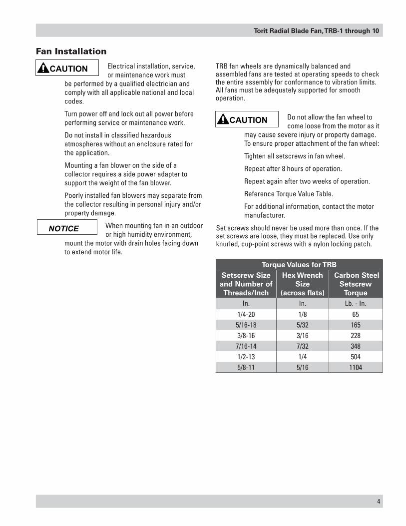
TRB fan wheels are dynamically balanced and assembled fans are tested at operating speeds to check the entire assembly for conformance to vibration limits. All fans must be adequately supported for smooth operation.
Do not allow the fan wheel to come loose from the motor as it
may cause severe injury or property damage. To ensure proper attachment of the fan wheel:
Tighten all setscrews in fan wheel.
Repeat after 8 hours of operation.
Repeat again after two weeks of operation.
Reference Torque Value Table.
For additional information, contact the motor manufacturer.
Electrical installation, service, or maintenance work must
be performed by a qualified electrician and comply with all applicable national and local codes.
Turn power off and lock out all power before performing service or maintenance work.
Do not install in classified hazardous atmospheres without an enclosure rated for the application.
Mounting a fan blower on the side of a collector requires a side power adapter to support the weight of the fan blower.
Poorly installed fan blowers may separate from the collector resulting in personal injury and/or property damage.
When mounting fan in an outdoor or high humidity environment,
mount the motor with drain holes facing down to extend motor life.
Fan Installation
Torque Values for TRBSetscrew Size and Number of Threads/Inch
Hex Wrench Size
(across flats)
Carbon Steel Setscrew
TorqueIn. In. Lb. - In.
1/4-20 1/8 655/16-18 5/32 1653/8-16 3/16 2287/16-14 7/32 3481/2-13 1/4 5045/8-11 5/16 1104
Set screws should never be used more than once. If the set screws are loose, they must be replaced. Use only knurled, cup-point screws with a nylon locking patch.

5
Donaldson Company, Inc.
1. TRB power packs are shipped assembled and partial disassembly is required before installing.
2. Disassemble the power pack by the blower housing fasteners and splitting the blower halves. The motor half contains the motor, half of the blower housing, and the blower wheel.
3. Apply sealant to the collector toward the outside edge of the bolt pattern.
Note: For top-mounted TRB with a blast-gate style damper, install a spacer ring between the blower housing and the collector to provide the necessary clearance for the damper installation.
4. Mount the inlet half of the blower housing (the one without the motor and fan wheel) to the collector using the hardware supplied.
5. Reattach the motor half of the blower housing to the inlet half of the blower housing. Apply sealant around fan case flange to inside of case flange bolt holes before reassembling.
6. Rotate the blower wheel after installation to ensure proper clearance between the inlet cone and the blower wheel.
Fan Installation
fan housingmotor half
fan housinginlet half
sealant
collector mounting surface
hex bolt flat washer
flat washer
hex nut
Torit Radial Blade Fan, TRB-1 through 10
6
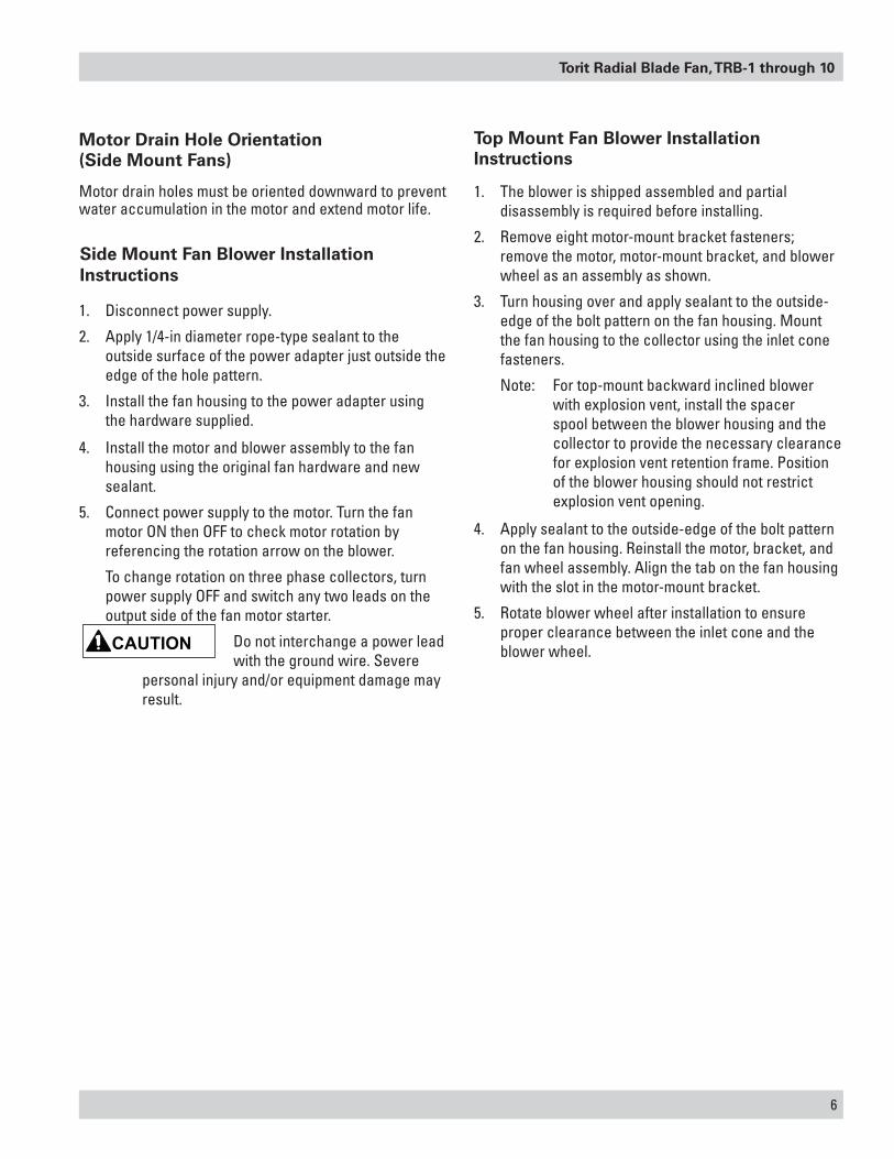
1. Disconnect power supply.
2. Apply 1/4-in diameter rope-type sealant to the outside surface of the power adapter just outside the edge of the hole pattern.
3. Install the fan housing to the power adapter using the hardware supplied.
4. Install the motor and blower assembly to the fan housing using the original fan hardware and new sealant.
5. Connect power supply to the motor. Turn the fan motor ON then OFF to check motor rotation by referencing the rotation arrow on the blower.
To change rotation on three phase collectors, turn power supply OFF and switch any two leads on the output side of the fan motor starter.
Do not interchange a power lead with the ground wire. Severe
personal injury and/or equipment damage may result.
Side Mount Fan Blower Installation Instructions
Top Mount Fan Blower Installation Instructions
1. The blower is shipped assembled and partial disassembly is required before installing.
2. Remove eight motor-mount bracket fasteners; remove the motor, motor-mount bracket, and blower wheel as an assembly as shown.
3. Turn housing over and apply sealant to the outside-edge of the bolt pattern on the fan housing. Mount the fan housing to the collector using the inlet cone fasteners.
Note: For top-mount backward inclined blower with explosion vent, install the spacer spool between the blower housing and the collector to provide the necessary clearance for explosion vent retention frame. Position of the blower housing should not restrict explosion vent opening.
4. Apply sealant to the outside-edge of the bolt pattern on the fan housing. Reinstall the motor, bracket, and fan wheel assembly. Align the tab on the fan housing with the slot in the motor-mount bracket.
5. Rotate blower wheel after installation to ensure proper clearance between the inlet cone and the blower wheel.
Motor Drain Hole Orientation (Side Mount Fans)
Motor drain holes must be oriented downward to prevent water accumulation in the motor and extend motor life.
7
Donaldson Company, Inc.
gasses” greater than 150°F (65°C) it is imperative that the blower be subjected to a gradual rate of temperature increase, not to exceed 15°F/minute (8°C/minute). The same temperature limits are also important when the blower is experiencing a drop in temperature until the temperature drops down to 150°F (65°C). Only when the entire blower has reached an equilibrium temperature of 150°F (65°C) or less, should the power be turned OFF.
11. Ensure the power source connections to the blower motor are per the motor manufacturer’s instructions.
12. Ensure the blower wheel is stationary prior to start-up. Starting a blower with a wheel that is rotating backwards can cause wheel damage.
Turn blower fan motor ON momentarily (i.e. bump start) to check for proper fan rotation as noted on the fan housing.
To reverse rotation, single-phase power supply: Follow manufacturer’s instructions on the motor’s nameplate.
To reverse rotation, three-phase power supply: Switch any two leads on the motor junction box.
Do not look into fan outlet to determine rotation. View the fan
rotation through the back of the motor.
Check that the exhaust plenum is free of tools or debris before checking blower/fan rotation.
Stand clear of exhaust to avoid personal injury.
Do not interchange a power lead with the ground wire. Severe damage or personal injury may result.
13. Apply power to the blower motor and let it come to full speed. Turn power OFF. Look and listen for any unusual noise or mechanical abnormality while the blower wheel is still spinning. If any are noticed, lock out the power, wait for blower wheel to come to a complete stop, locate the cause and correct it.
14. Unlock power and start the blower.
Initial Fan Start-Up
Instruct all personnel on safe use and maintenance procedures.
Electrical work during installation, service or
maintenance must be performed by a qualified electrician and comply with all applicable national and local codes.
Turn power off and lock out electrical power sources before performing service or maintenance work.
Check that the collector is clear and free of all debris before starting.
Do not install in classified hazardous atmospheres without an enclosure rated for the application.
Optional fans over 600 lbs must be independently supported.
1. If possible, carefully spin the blower wheel by hand to ensure it rotates freely and no rubbing or clicking noise is heard.
2. Check that all blower mounting flange and duct work hardware is tight.
3. Check all blower wheel set screws tare tight per Torque Values table found in this manual.
4. Make certain there is no foreign material in the blower or duct work that can be become a projectile.
5. Ensure any inspection doors in the duct work are securely bolted or locked.
6. Ensure all electrical power components are properly sized and matched for electrical system.
7. Check that all required guards are properly secured.
8. Dampers should be fully opened and closed to make sure their is no binding or interference.
9. If blower is mounted on an elevated support structure, make sure the structure is welded at all joint connections and the structure is properly braced to prevent “side sway”.
10. Close any dampers to minimize load on motor, especially on blowers with high temperature construction. Never subject a “cold” blower to a “hot” gas stream. If the blower will be handling “hot
Torit Radial Blade Fan, TRB-1 through 10
8
Vibration
If the blower is going to be conveying material, it is the users responsibility to periodically turn the blower off and lock out the power.
The blower wheel should then be checked for material build-up and/or erosion. If material has built up on any parts of the wheel, it must be removed and cleaned before it is put back into service.
If any parts of the wheel have been eroded, the wheel must be replaced. Failure to perform this inspection can cause excessive vibration that will damage the blower and/or motor bearings. When vibration becomes excessive, it will lead to complete blower failure that could cause property damage, severe personal injury and death.
The user must determine the frequency of this inspection based on the actual circumstances of their operation, but check the vibration readings should never exceed a 12 month period.
The blower was balanced at the factory to comply with ANSI/AMCA Standard 204-05, Category BV-2. However, rough handling in shipment and/or erection, weak and/or non-rigid foundations and misalignment may cause a vibration problem after installation. After installation, the vibration levels should be checked by personnel experienced with vibration analysis and vibration analysis equipment.
Note: The blower should not be operated if the vibration velocity of the fan exceeds 0.50 inches per second, filter out, with the blower rigidly mounted.
Vibration readings for direct driven blowers should be taken on the motor at the top, sides, and end.
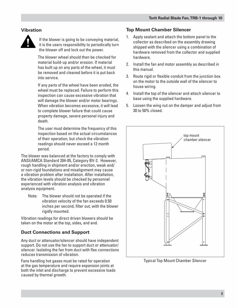
Top Mount Chamber Silencer
1. Apply sealant and attach the bottom panel to the collector as described on the assembly drawing shipped with the silencer using a combination of hardware removed from the collector and supplied hardware.
2. Install the fan and motor assembly as described in this manual.
3. Route rigid or flexible conduit from the junction box on the motor to the outside wall of the silencer to house wiring.
4. Install the top of the silencer and attach silencer to base using the supplied hardware.
5. Loosen the wing nut on the damper and adjust from 30 to 50% closed.
Duct Connections and Support
Any duct or attenuator/silencer should have independent support. Do not use the fan to support duct or attenuator/silencer. Isolating the fan from duct with flex connections reduces transmission of vibration. Fans handling hot gases must be rated for operation at the gas temperature and require expansion joints at both the inlet and discharge to prevent excessive loads caused by thermal growth.
Typical Top Mount Chamber Silencer
top mount chamber silencer
9
Donaldson Company, Inc.
Donaldson Torit TRB fans are manufactured to high standards with quality materials and components. Proper maintenance will ensure a long and trouble-free service life.
Motor Maintenance
TRB Fans typically use motors with sealed bearings that are permanently lubricated for the life of the motor, but other types of motors may have been selected for your fan.
The key to good fan maintenance is regular and systematic inspection of all fan parts. Inspection frequency is determined by the severity of the application and local conditions. Strict adherence to an inspection schedule is essential.
Regular fan maintenance should include the following:
Check the fan wheel for any wear or corrosion, as either can cause catastrophic failures. Check also for the build-up of material which could cause unbalance resulting in vibration, bearing wear and serious safety hazards. Clean or replace the wheel as required.
Lubricate the bearings, but do not over lubricate.
Periodically inspect the shaft for dirt buildup, corrosion and signs of excess stress or fatigue.
During any routine maintenance, all setscrews and bolts should be checked for tightness. See Torque Value Table.
Maintenance Information
Instruct all personnel on safe use and maintenance procedures.
Use proper equipment and adopt all safety precautions needed
for servicing equipment.
Electrical service or maintenance work must be performed by a qualified electrician and comply with all applicable national and local codes.
Turn power off and lock out electrical power sources before performing service or maintenance work.
Do not install in classified hazardous atmospheres without an enclosure rated for the application.
When mounting fan in an outdoor or high humidity environment,
mount the motor with drain holes facing down to extend motor life.
For additional information, contact the motor manufacturer.
Torit Radial Blade Fan, TRB-1 through 10
10
Grease Motors
Use the following steps for greaseable motors only:
1. Inspect the motor at approximately every 500 hours of operation or every 3 months, whichever occurs first.
2. Keep the motor clean and the ventilation openings clear. If the motor is not properly ventilated overheating can occur.
3. Use an electrical insulation tester to periodically ensure that the integrity of the winding insulation has been maintained. Investigate any significant drop in resistance.
4. Grease the motor bearings using a high grade bearing grease. For standard service conditions ExxonMobil Polyrex™ EM grease is recommended.
Under standard conditions, grease every 5,500 hours. In severe dirt and abrasive dust conditions, grease every 2750 hours. Under extreme conditions, such as an environment with iron dust, grease every 550 hours.
Wheel Balance
Airstreams containing particulate or chemicals can cause abrasion or corrosion of the fan parts. This is often uneven and can lead to wheel imbalance over time. When such wear is discovered, a decision must be made to rebalance or replace the wheel.
The soundness of all parts should be determined making sure there is no hidden structural damage. The airstream components should also be cleaned to remove any build-up of foreign material. Specialized equipment can be used to rebalance a cleaned wheel that is considered structurally sound.
Balance weights should be rigidly attached at a point that will not interfere with the housing nor disrupt airflow.
Troubleshooting Guidelines
Use current safety practices when investigating fan or system performance problems. General safe practices and performance troubleshooting guidelines can be found in AMCA Publications 410 and 202, respectively. Fan application and field measurement procedures can be found in AMCA Publications 201 and 203.
ExxonMobil Polyrex™ EM is a trademark of Exxon Mobil Corporation

11
Donaldson Company, Inc.
Troubleshooting
Problem Probable Cause Remedy
Fan blower and motor do not start
Improper motor wire size Rewire using the correct wire gauge as specified by national and local codes.
Not wired correctly Check and correct motor wiring for supply voltage. See motor manufacturer's wiring diagram. Follow wiring diagram and the National Electric Code.
Collector not wired for available voltage
Correct wiring for proper supply voltage.
Input circuit down Check power supply to motor circuit on all leads.Electrical supply circuit down Check power supply circuit for proper voltage.
Check for fuse or circuit breaker fault. Replace as necessary.
Damaged motor Replace damaged motor.Fan blower and motor start, but do not stay running
Incorrect motor starter installed Check for proper motor starter and replace if necessary.
Access doors are open or not closed tight
Close and tighten access doors. See Filter Installation.
Hopper discharge open Check that dust container is installed and properly sealed.
Damper control not adjusted properly
Check airflow in duct. Adjust damper control until proper airflow is achieved and the blower motor’s amp draw is within the manufacturer’s rated amps.
Electrical circuit overload Check that the power supply circuit has sufficient power to run all equipment.
Insufficient airflow Fan rotation backwards Proper fan rotation is clockwise when viewed from the motor side or counterclockwise when viewed through the inlet cone. See Preliminary Start-Up Check.
Access doors open or not closed tight
Check that all access doors are in place and secured. Check that the hopper discharge opening is sealed and that dust container is installed correctly.
Fan exhaust area restricted Check fan exhaust area for obstructions. Remove material or debris. Adjust damper flow control.
Filters need replacement Remove and replace using genuine Donaldson replacement filters. See Filter Removal and Installation.
Excessive vibration Loose mounting bolts or set screws
Tighten loose bolts or set screws.
Misalignment or excessive wear of wheel
Align wheel and balance fan.
Misaligned or unbalanced motor Balance fan.
Bent shaft due to mishandling or material impact
Replace motor with bent shaft and rebalance fan.

Torit Radial Blade Fan, TRB-1 through 10
12
Problem Probable Cause Remedy
Excessive vibration Externally transmitted vibration Isolate collector from external vibration.Accumulation of foreign material on the wheel
Clean the wheel.
Excessive system pressure or restriction of airflow due to closed dampers
Open dampers far enough for fan to operate in stable flow regime.
Inadequate performance Fan running too slowly Check power frequency against fan motor design frequency.
Fan wheel rotating in wrong direction or installed backwards on shaft
Proper fan rotation is clockwise from the top of the fan. The fan can be viewed through the back of the motor.
Poor system design, closed dampers, air leaks or clogged filters
Check system for damper positions leak points. Check filter Delta P.
Sharp deflection of airstream at fan outlet
Do not place fan discharge next to a wall.
Missing discharge fittings Install discharge fittings.Excessive noise Fan operating near “stall” due
to incorrect system design or installation
Correct system or replace with correctly sized fan.
Vibration originating elsewhere in the system
Isolate collector vibration from the system.
Loose accessories or components
Tighten accessories or components.
Bent motor shaft Replace motor.Fan wheel out of balance Balance wheel.Worn motor bearings Replace bearings.Motor bearing needs lubrication Lubricate motor bearing.Worn or corroded blower wheel Replace blower wheel.Accumulation of foreign material on blower wheel
Clean and rebalance blower wheel.
Motor overheating Actual system static pressure (SP) is lower than expected
Close damper.
Voltage supplied to motor is too high or too low
Rewire motor.
Motor speed (RPM) too high or defective motor
Replace motor.
Cooling fan cover on back of motor is clogged
Clean cooling fan motor.
Bad motor bearings Replace motor.

13
Donaldson Company, Inc.
Model Number _____________________________ Serial Number ______________________________
Ship Date _________________________________ Installation Date _____________________________
Filter Type ____________________________________________________________________________
Collected Dust ________________________________________________________________________
Dust Properties: Kst ______________Pmax _____________MIE ___________MEC ________________
Accessories __________________________________________________________________________
Other ________________________________________________________________________________
____________________________________________________________________________________
Product Information (Process Owner to complete and retain for your records)
Torit Radial Blade Fan, TRB-1 through 10
14
Service Notes
Date Service Performed Notes

15
Donaldson Company, Inc.
Service Notes
Date Service Performed Notes
Torit Radial Blade Fan, TRB-1 through 10
16
Donaldson warrants to the original purchaser only that the Goods will be free from defects in material and manufacture for the applicable time periods stated below: (1) Major structural components for a period of ten (10) years from the date of shipment; (2) Non-Structural, Donaldson-built components and accessories including Donaldson Airlocks, TBI Fans, TRB Fans, Fume Collector products, Donaldson built electrical control components, and Donaldson-built Afterfilter housings for a period of twelve (12) months from date of shipment; and (3) Donaldson-built filter elements for a period of eighteen (18) months from date of shipment.
Buyer is solely responsible for determining if goods fit Buyer’s particular purpose and are suitable for Buyer’s process and application. Seller’s statements, engineering and technical information, and recommendations are provided for the Buyer’s convenience and the accuracy or completeness thereof is not warranted. If, after Seller receives written notice, within the warranty period, that any goods allegedly do not meet Seller’s warranty, and Seller, in its sole discretion, determines that such claim is valid, Seller’s sole obligation and Buyer’s exclusive remedy for breach of the foregoing warranty or any Seller published warranty, will be, at Seller’s option, either: (i) repair or replacement of such goods or (ii) credit or refund to Buyer for the purchase price from Seller. In the case of repair or replacement, Seller will be responsible for the cost of shipping the parts but not for labor to remove, repair, replace or reinstall the allegedly defective goods. Refurbished goods may be used to repair or replace the goods and the warranty on such repaired or replaced goods shall be the balance of the warranty remaining on the goods which were repaired or replaced. Any repair or rework made by anyone other than Seller is not permitted without prior written authorization by Seller, and voids the warranty set forth herein. Seller warrants to Buyer that it will perform services in accordance with the Sales Documents using personnel of required skill, experience and qualifications and in a professional and workmanlike manner in accordance with generally recognized industry standards for similar services. With respect to any services subject to a claim under the warranty set forth above, Seller shall, in its sole discretion, (i) repair or re-perform the applicable services or (ii) credit or refund the price of such services at the pro rata contract rate and such shall be Seller’s sole obligation and the exclusive remedy for breach of the foregoing warranty on services. Products manufactured by a third party (“Third Party Product”) may constitute, contain, be contained in, incorporated into, attached to or packaged together with, the goods. Buyer agrees that: (a) Third Party Products are excluded from Seller’s warranty in this Section 7 and carry only the warranty extended by the original manufacturer, and (b) Seller’s liability in all cases is limited to goods of Seller’s design and manufacture only. EXCEPT FOR SELLER’S WARRANTY OF TITLE TO THE GOODS, SELLER EXPRESSLY DISCLAIMS AND EXCLUDES ALL OTHER WARRANTIES WHATSOEVER, WHETHER, EXPRESSED OR IMPLIED, ORAL, STATUTORY, OR OTHERWISE, INCLUDING BUT NOT LIMITED TO MERCHANTABILITY, FITNESS FOR A PARTICULAR PURPOSE, NON-INFRINGEMENT OF THIRD PARTY INTELLECTUAL PROPERTY AND ANY WARRANTIES ARISING FROM TECHNICAL ADVICE OR RECOMMENDATIONS, COURSE OF DEALING OR OF PERFORMANCE, CUSTOM OR USAGE OF TRADE. Seller’s obligations do not cover normal wear and tear or deterioration, defects in or damage to any goods resulting from improper installation, accident or any utilization, maintenance, repair or modification of the goods, or any use that is inconsistent with Seller’s instructions as to the storage, installation, commissioning or use of the goods or the designed capabilities of the goods or that, in its sole judgment, the performance or reliability thereof is adversely affected thereby, or which is subjected to abuse, mishandling, misuse or neglect or any damage caused by connections, interfacing or use in unforeseen or unintended environments or any other cause not the sole fault of Seller, and shall be at Buyer’s expense. Seller’s warranty is contingent upon the accuracy of all information provided by Buyer. Any changes to or inaccuracies in any information or data provided by Buyer voids this warranty. Seller does not warrant that the operation of the goods will be uninterrupted or error-free, that the functions of the goods will meet Buyer’s or its customer’s requirements unless specifically agreed to, or that the goods will operate in combination with other products selected by Buyer or Buyer’s customer for its use.
The terms of this warranty may only be modified by a special warranty document signed by a Director, General Manager or Vice President of Donaldson. To ensure proper operational performance of your equipment, use only genuine Donaldson replacement parts.
This Product is provided subject to and conditioned upon Donaldson’s Terms of Sale (“Terms”), a current copy of which is located at termsofsale.donaldson.com. These Terms are incorporated herein by reference. By purchasing or using this Product, the user accepts these Terms. The Terms are available on our website or by calling our customer service line at 1-800-365-1331.
Donaldson Industrial Air Filtration Warranty

IOM AG8130401 (ENG), Revision 2 (October 2018) ©2014-2018 Donaldson Company, Inc. Donaldson, Torit and the color blue are marks of Donaldson Company, Inc. All other marks belong to their respective owners.
Donaldson Company, Inc. Minneapolis, MN
donaldsontorit.com • shop.donaldson.com
North AmericaEmail: [email protected] Phone: (USA): 800-365-1331 • (MX): 800-343-3639
AustralasiaEmail: [email protected] Phone: +61 2 4350 2000 Toll Free: (AU) 1800 345 837 • (NZ) 0800 743 387
China IAFEmail: [email protected] Phone: (86) 400-820-1038
Donaldson Europe B.V.B.A.Email: [email protected] Phone: + 32 (0) 16 38 38 11
IndiaEmail: [email protected] Phone: +91 124 4807400 Toll Free: 18001035018
LatinoamericaEmail: [email protected] Phone: +52 449 300 2442
South AfricaEmail: [email protected] Phone: +27 11 997 6000
Southeast Asia IAFEmail: [email protected] Phone: (65) 63117373
Important NoticeMany factors beyond the control of Donaldson can affect the use and performance of Donaldson products in a particular application, including the conditions under which the product is used. Since these factors are uniquely within the user’s knowledge and control, it is essential the user evaluate the products to determine whether the product is fit for the particular purpose and suitable for the user’s application. All products, product specifications, availability and data are subject to change without notice, and may vary by region or country.
Significantly improve the performance of your collector with genuine Donaldson Torit replacement filters and parts. Call Donaldson Torit at 800-365-1331.