Topics Today - Stanford University
36
Topics Today • Physical layer: chips versus bits • Link layer • Media access control (MAC) • Ethernet • MPLS
Transcript of Topics Today - Stanford University

Topics Today
• Physical layer: chips versus bits
• Link layer
• Media access control (MAC)
• Ethernet
• MPLS

Protocol Layering
SessionTransportNetworkLink
Physical
PresentationApplication7
654321

Protocol Layering
SessionTransportNetworkLink
Physical
PresentationApplication7
654321
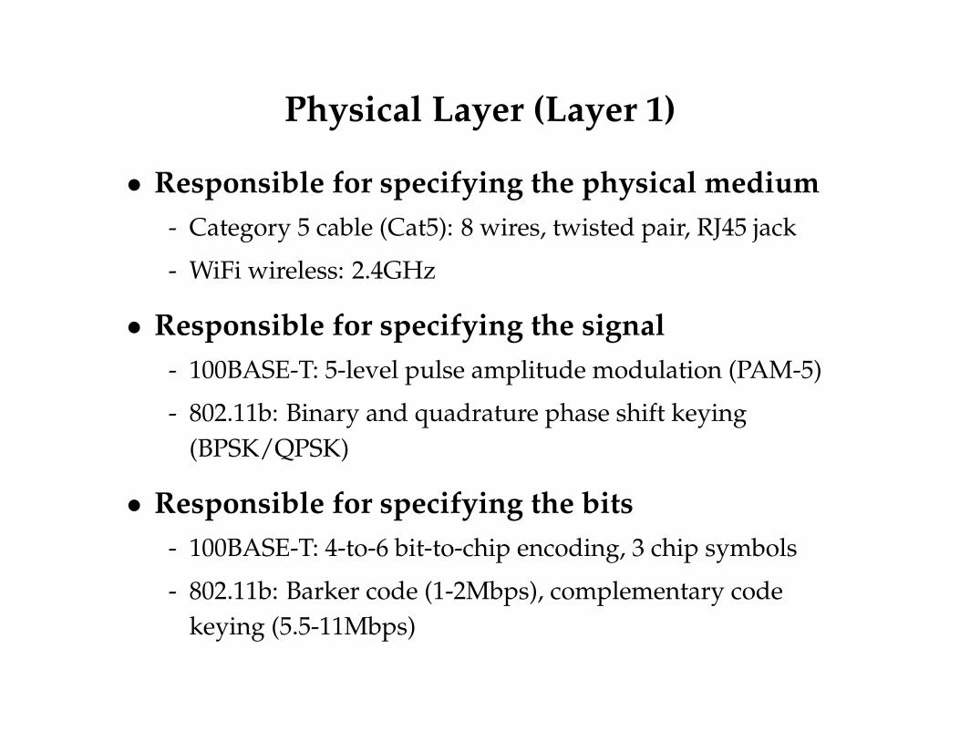
Physical Layer (Layer 1)
• Responsible for specifying the physical medium- Category 5 cable (Cat5): 8 wires, twisted pair, RJ45 jack
- WiFi wireless: 2.4GHz
• Responsible for specifying the signal- 100BASE-T: 5-level pulse amplitude modulation (PAM-5)
- 802.11b: Binary and quadrature phase shift keying(BPSK/QPSK)
• Responsible for specifying the bits- 100BASE-T: 4-to-6 bit-to-chip encoding, 3 chip symbols
- 802.11b: Barker code (1-2Mbps), complementary codekeying (5.5-11Mbps)

Specifying the signal
• Chips versus bits- Chips: data (in bits) at the physical layer
- Bits: data above the physical layer
• Physical layer specifies Analog signal↔ chipmapping

How fast can you transmit information?• Depends on bandwidth and Signal/Noise ration
• Shannon: Channel capacity C = B log2(1 + S/N)
- B is bandwidth of line
- S and N are average signal & noise power
• For any transmission rate R < C, can have arbitrarilylow error rate
• Example: Telephone line- 3 KHz b/w, 30 db S/N = 1030/10 = 1000
- C ≈ 30 Kbps (so 56 Kbps modems need better S/N ratio)
• Crude intuition for Shannon- Sample rate ∼ B
- V voltage levels encode log2 V bits, so bits/sample ∼ log2(1 + S/N)

Straw man: On-off keyingBits
NRZ
0 0 1 0 1 1 1 1 0 1 0 0 0 0 1 0
• To transmit 0 bit, sent 0 V , to transmit 1, sent +5 V
- A bit is a chip in this scheme
• OOK a form of Amplitude Shift Keying (ASK)- Bits are encoded in amplitude of the signal
- Can also have frequency shift keying (FSK)
- And phase shift keying (PSK)
• Also an example of non-return to zero (NRZ)- E.g., four 1 bits transmitted by asserting +5 V for 4 clock ticks

NRZ drawbacks
• Consecutive 1s or 0s are problematic
• Non signal could be interpreted as 0s (or viceversa)
• “Baseline wander” problem- Where is threshold between low and high?
- Could compare signal to average value, but avg. will drift
• Sender and receiver need synchronized clocks- Otherwise, can experience “bit slip”

Non-return to Zero Inverted (NRZI)
• Encode 1 with transition from current signal
• Encode 0 by staying at same level
• At least solves problem of consecutive 1s

Encoding Goals• DC balancing (same number of 0 and 1 chips)
• Clock synchronization
• Can recover from some chip errors
• Can constrain analog signal patterns to makesignal more robust
• Want near-chanel capacity with negligible errors- But Shannon only says it’s possible, doesn’t tell us how
- Codes could also get computationally expensive
• In practice:- Higher encoding→ fewer bps, more robust
- Lower encoding→more bps, less robust

Manchester Encoding• Map bit 0→ chips 01, bit 1→ chips 10
- Transmission rate now 1 bit per two clock cycles
- Like XORing an NRZ encoding with the clock
5.5.2 CSMA/CD: Ethernet’s Multiple Access Protocol
Nodes in an Ethernet LAN are interconnected by a broadcast channel, so that whenan adapter transmits a frame, all the adapters on the LAN receive the frame. As wementioned in Section 5.3, Ethernet uses a CSMA/CD multiple access algorithm.Summarizing our discussion from Section 5.3, recall that CSMA/CD employs thefollowing mechanisms:
1. An adapter may begin to transmit at any time; that is, no slots are used.2. An adapter never transmits a frame when it senses that some other adapter is
transmitting; that is, it uses carrier sensing.3. A transmitting adapter aborts its transmission as soon as it detects that another
adapter is also transmitting; that is, it uses collision detection.4. Before attempting a retransmission, an adapter waits a random time that is typ-
ically small compared with the time to transmit a frame.
These mechanisms give CSMA/CD much better performance than slottedALOHA in a LAN environment. In fact, if the maximum propagation delay betweenstations is very small, the efficiency of CSMA/CD can approach 100 percent. Butnote that the second and third mechanisms listed above require each Ethernetadapter to be able to (1) sense when some other adapter is transmitting, and (2) de-tect a collision while it is transmitting. Ethernet adapters perform these two tasks bymeasuring voltage levels before and during transmission.
Each adapter runs the CSMA/CD protocol without explicit coordination withthe other adapters on the Ethernet. Within a specific adapter, the CSMA/CD proto-col works as follows:
1. The adapter obtains a network-layer PDU from its parent node, prepares anEthernet frame, and puts the frame in an adapter buffer.
460 CHAPTER 5 � Link Layer and Local Area Networks
Figure 5.24 Manchester encoding
Bit stream
Manchesterencoding
Binaryencoding
Time
1 0 0 0 1 0 0 1 1 1 1
02-068 C05 pp4 6/14/02 3:01 PM Page 460
• Solves clock synchronization & baseline wander
• But cuts transmission rate in half

4B/5B
• Every 4 bits of data encoded in 5 chips
• 5-bit codes selected to have no more than oneleading 0 and no more than two trailing 0s
- thus, never get more than three consecutive 0s
• 16 codes used for all 4-bit sequences
• Resulting 5bit codes are transmitted using NRZI
• Remaining codes used for other purposes- E.g., 11111 – line idle, 00000 – line dead, . . .
• Achieves 80% bit/chip efficiency

802.15.4
• Standard for low-rate wireless personal networks- Must tolerate high chip error rates
• Uses a 32-to-4 chip-to-bit encoding
0011001000010000
1111
1 1 0 1 1 0 0 1 1 1 0 0 0 0 1 1 0 1 0 1 0 0 1 0 0 0 1 0 1 1 1 01 1 1 0 1 1 0 1 1 0 0 1 1 1 0 0 0 0 1 1 0 1 0 1 0 0 1 0 0 0 1 00 0 1 0 1 1 1 0 1 1 0 1 1 0 0 1 1 1 0 0 0 0 1 1 0 1 0 1 0 0 1 00 0 1 0 0 0 1 0 1 1 1 0 1 1 0 1 1 0 0 1 1 1 0 0 0 0 1 1 0 1 0 1
1 1 0 0 1 0 0 1 0 1 1 0 0 0 0 0 0 1 1 1 0 1 1 1 1 0 1 1 1 0 0 0
Bits Chips
Symbols

Physical Layer Frames
• Usually minimalist: “here’s N bytes”- Start symbol/preamble
- Length field
- Payload (link layer frame)
Pre L Data

Link Layer Responsibilities
• Single-hop addressing (e.g., Ethernet addresses)
• Media access control- Link-layer congestion control
- Collision detection/collision avoidance
• Single-hop acknowledgements

Ethernet: 802.3
• Dominant wired LAN technology- 10BASE5 (vampire taps)
- 10BASE-T, 100BASE-TX, 1000BASE-T
• Frame format:
Preamble Type/Len Payload
7 x 10101010
SFD10101011
Src6 bytes 2 bytes 46-1500 bytes
CRC4 bytes
Gap96 ns,960 ns,9600 ns
Physical Link LinkLayer 3
Dest6 bytes

Ethernet Addressing
• Each Ethernet card has a unique 48-bit ID- Example: www.scs.stanford.edu has 00:07:e9:0f:1f:3e
- Example: myth15 has 00:1e:c9:2f:a2:9c
• 24-bit organizationally unique identifier, 24-bit ID- 0x000000–0x000009: Xerox
- 0x0007e9: Intel (www.scs)
- 0x001ec9: Dell (myth15)
- http://standards.ieee.org/regauth/oui/oui.txt

Media Access Control (MAC)
• Control access to shared physical medium- E.g., who can use coax/radio when?
- If everyone talks at once, no-one hears anything
- This job falls to the link layer
• Prevent collisions by controlling when nodes send
• Variety of approaches- Time Division Multiple Access (TDMA)
- Carrier Sense Multiple Access, Collision Detection(CSMA/CD)
- Carrier Sense Multiple Access, Collision Avoidance(CSMA/CA)
- Request-to-send, clear-to-send (RTS/CTS)

MAC Approaches• Channel Partitioning
- Divide channel into smaller “pieces,” allocate pieces tonodes
• Random Access- Don’t divide channel, allow conflicts
- Recover from errors caused by conflicts
• “Taking turns”- Nodes take turns, but nodes with more to send can take
longer turns
• MAC goals: Maximize use of the link capacity- One node should get 100% in absence of competition
- Multiple nodes can each get a share, not collide

TDMA• Divide time into slots
- Each device is allowed to transmit in some number of slots
• No collisions
• Link is fully utilized when everyone transmits:
1 2 3 4 1 2 3 4 1 2 3 4 1 2 3 4
• Single node cannot use all of the capacity ( 1n
):
11 11
• Can’t get full link utilization unless everyonetransmits:
1 4 1 2 4 21 4 1

CSMA
• Node senses the channel for activity
• Transmits if it thinks the channel is idle
• CSMA/CD: can detect if there is a collision, andback off
- Randomized backoff time, grows exponentially
- After C consecutive collisions, wait rand(0, 2C) · 512
- Drop when C grows large (in practice)

Collision Detect (10base2 Ethernet)
• Detect collision when average voltage spikes- 10base2 uses Manchester encoding
- Has constant average voltage unless multiple transmitters
• When a node detects a collision- Broadcasts jam signal to ensure other nodes drop packet
• Collision detection constrains protocol- Imposes min. packet size (64 bytes)
- Imposes maximum network diameter (2800 m)
- Ensure transmission time ≥ twice propagation time—why?

Violating Timing Constraints
Time
CollisionDetect
No CollisionDetect!
• Without min packet size, might miss collision
Ethernet Capture Effect
• Exponential backoff leads to self-adaptive use ofchannel
• When a node succeeds, it transmits the next packetimmediately
• Result: bursts of packets from single nodes

Ethernet Speeds
• Network diameter limits:- 10Mbps: 2800m
- 100Mbps: 205m
- Gigabit: 205m!
• Gigabit Ethernet- Uses more of the CAT5 wires (125 MHz · 8 signals)
- Pad with dummy data (signal extension) for CD(so min packet size is now 512 bytes, not bits)
Hubs vs. Switches
• Hub: connects multiple Ethernet segments to actlike a single segment (shared collision domain,physical layer connectivity)
• Switch: store and forward between segments(single collision domains, link layer connectivity)
• Very little Ethernet today is shared- Means collision detection never triggered (duplex, separate
RX and TX wires)
- 10Gbps Ethernet standard does not allow shared medium

Bridges and extended LANsA
Bridge
B C
X Y Z
Port 1
Port 2
• LANs have physical limitations (e.g., 208 m)
• Connect two or more LANs with a bridge- Operates on Ethernet addresses
- No encapsulation required
• Ethernet switch like a multi-way bridge

Learning bridgesA
Bridge
B C
X Y Z
Port 1
Port 2
• Idea: Don’t forward packet if not useful- If you know recipient is not on that port
• Learn host’s location based on source address- Switch builds a table when it receives packets
A B C X Y Z
1 1 1 2 2 2
• Table says when not to forward packet- Does not need to be complete for correct behavior
- Spanning tree algorithm avoids loops

Congestion Interaction
• Congestion can occur at layer 2 (collisions, highutilization)
• Congestion control can occur at layer 2 (backoff)
• Congestion can occur at layer 3 (packet drops)
• Congestion control can occur at layer 4 (rateadaptation)
• Interactions are non-trivial

ARP and DHCP, revisited
• DHCP allows a node to dynamically obtain an IPaddress, netmask, and gateway
• Address Resolution Protocol maps IP addresses tolink address
• Common exchange:- Broadcast DHCP discover
- Receive gateway IP address IPG, local address IPA
- ARP to get gateway address IPG (announcing self), receiveEtherG
- Send packet to IPB using EtherG as next hop
• What if node is on the subnet?

Layer 2 Acknowledgements
• Common in wireless (more on this in wirelesslecture)
• If layer 2 successfully receives a frame, itimmediately sends an ACK
• Assumes tprop << ttrans
• Hypothetical situation:- Let’s say a router won’t send an ACK if it drops the packet
- Let’s say a router will keep on retrying a packet until it isACKed
- Do we still need end-to-end ACKs?

Ack Effect on CSMA
• Layer 2 acks require two channel checks
• Want to make sure we don’t check between packetand ACK
AckData
CSMA check

MPLS
• Multiprotocol Label Switching
• Sits between layer 2 and 3 (“layer 2.5”)
• Prepend a “label” to frame
• Switch in terms of label, rather than destinationaddress
- Two packets to the same destination can take different paths
- Separating addressing from forwarding enables trafficengineering
- Label changes from input to output

MLPS packet format
• 20-bit label
• 3 experimental bits
• 1 “bottom of stack bit”- Allows multiple MPLS headers to be stacked in a packet
• 5-bit TTL (since network-level TTL not used)

MLPS Architecture
• Label Edge Routers (LERs)- Talks to regular IP routers and MPLS-enabled ones
• Label Switch Routers (LSRs)- E.g., The core routers in a large backbone provider
• Label Distribution Protocol (LDP)
• Label Forwarding Information Base (LFIB)

Example MPLS (from textbook)