To the Stage of Control Panel Coolers The Advent of … · The Advent of the Next-Generation,...
14
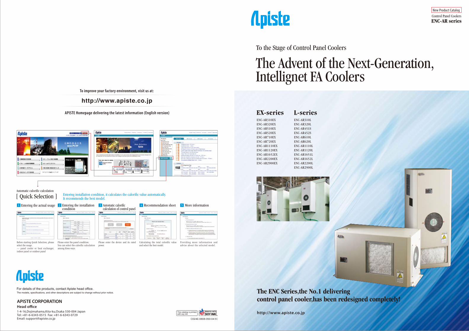
The Advent of the Next-Generation, Intellignet FA Coolers To the Stage of Control Panel Coolers Control Panel Coolers New Product Catalog The ENC Series,the No.1 delivering control panel cooler,has been redesigned completely! ENC-AR series EX-series L-series ENC-AR310EX ENC-AR320EX ENC-AR510EX ENC-AR520EX ENC-AR710EX ENC-AR720EX ENC-AR1110EX ENC-AR1120EX ENC-AR1652EX ENC-AR2200EX ENC-AR2900EX ENC-AR310L ENC-AR320L ENC-AR451S ENC-AR452S ENC-AR610L ENC-AR620L ENC-AR1110L ENC-AR1120L ENC-AR1651L ENC-AR1652L ENC-AR2200L ENC-AR2900L http://www.apiste.co.jp Head office 1-4-16,Dojimahama,Kita-ku,Osaka 530-004 Japan Tel: +81-6-6343-0515 Fax: +81-6-6343-0729 Email: [email protected] http://www.apiste.co.jp To improve your factory environment, visit us at: For details of the products, contact Apiste head office. The models, specifications, and other descriptions are subject to change without prior notice. APISTE Homepage delivering the latest information (English version) APISTE CORPORATION Please enter the device and its rated power. Automatic calorific calculation of control panel Calculating the total colorific value and select the best model. Recommendation sheet Providing more information and advise about the selected model. More information Please enter the panel condition. You can select the calorific calculation among three ways. Entering the installation condition Entering the actual usage 1 2 3 4 5 Automatic calorific calculation [ Quick Selection ] Entering installation condition, it calculates the calorific value automatically. It recommends the best model. Before starting Quick Selection, please select the usage. --- panel cooler or heat exchanger, indoor panel or outdoor panel C024E-0808-050-04(K)
Transcript of To the Stage of Control Panel Coolers The Advent of … · The Advent of the Next-Generation,...
The Advent of the Next-Generation,Intellignet FA Coolers
To the Stage of Control Panel Coolers
Control Panel Coolers
New Product Catalog
The ENC Series,the No.1 deliveringcontrol panel cooler,has been redesigned completely!
ENC-AR series
EX-series L-seriesENC-AR310EXENC-AR320EXENC-AR510EXENC-AR520EXENC-AR710EXENC-AR720EXENC-AR1110EX ENC-AR1120EXENC-AR1652EXENC-AR2200EXENC-AR2900EX
ENC-AR310LENC-AR320LENC-AR451SENC-AR452SENC-AR610LENC-AR620LENC-AR1110LENC-AR1120LENC-AR1651LENC-AR1652LENC-AR2200LENC-AR2900L
http://www.apiste.co.jpHead o�ce1-4-16,Dojimahama,Kita-ku,Osaka 530-004 JapanTel: +81-6-6343-0515 Fax: +81-6-6343-0729Email: [email protected]
http://www.apiste.co.jpTo improve your factory environment, visit us at:
For details of the products, contact Apiste head office.The models, specifications, and other descriptions are subject to change without prior notice.
APISTE Homepage delivering the latest information (English version)
APISTE CORPORATION
Please enter the device and its rated power.
Automatic calorific calculation of control panel
Calculating the total colorific value and select the best model.
Recommendation sheet
Provid ing more informat ion and advi se about the se lec ted model .
More information
Please enter the panel condition. You can select the calorific calculation among three ways.
Entering the installation condition
Entering the actual usage1 2 3 4 5
Automatic calorific calculation
[ Quick Selection ] Entering installation condition, it calculates the calorific value automatically. It recommends the best model.
Before starting Quick Selection, please select the usage. --- panel cooler or heat exchanger, indoor panel or outdoor panel
C024E-0808-050-04(K)

�ENC series˝Protect control panels from break down and troubles!
Entrust Apiste whenever, wherever!
Heat
● Effect
● Digest Features
Moisture EX-series ( Top mount ) L-series ( Side mount )
EX-series ( Top mount ) L-series ( Side mount )
Dust Particle
Electric devices and controllers are facing severe condition
By temperature rising,electric devices are deteriorated andbroken down.
Moisture brings corrosion, rust, insulation deterioration and a short circuit accident.
Fire, operation deterioration and insulation deterioration are occurred byparticles and oil mist.
Note: This is a composite photograph. Some parts may differ one an actual machine.
Note: This is a composite photograph. Some parts may differ one an actual machine.
Multi-digitalcontrol panel
Multi-digitalcontrol panel
Double-panel-structureair-cutoff panel
Condenser
Condenser
Cooling fan
Condenser fan Condenser fan
FilterFilter
Compressor for CFC substitute
For die casting machine panel For painting robot panel For NC machine panel For film molding base panel
For generator panel For furnace panel For stamping press panel For wire forming panel
Compressor for CFC substitute
by InternalAir-Circulation
Direct easymounting
Automatic temperaturehumidity control
Mild coolingwithout condensation
Easy maintenanceDiagnosis function
What’s the problem of control panels ? Design
What’s Apiste’s Panel Cooler “ENC series” ?
Application
Cooling
Dehumidification
Dust Prevention
&
&
1 2

With the rapidly growing globalization of the marketplace and the necessity for worldwide cost competi-tiveness, it is urgent to improve production efficiency in factories or to establish an automation system.Apiste’s idea is that it is also a new age for control panel coolers, which are indispensable for such sophisti-cated production systems.Witness the advent of the next-generation co ntrol panel cooler, offering unprecedented safety and reliability.
Self-diagnosis Function for Ultimate SafetyApiste’s FA coolers are designed to provide doubled or tripled safety measures all of the time.They conduct continuous self-diagnosis and monitor cooling operations in real time.
250V, 2 ARelay output
Buzzer
Signal tower
Voice
Indicators
Apiste’s cooler’s self-diagnosis function not only detects clogged filters but also checks various points. The safety-conscious design monitors operation in real time and provides alarm display and external output when an abnormal condition is detected. Coolers that only cool are behind the times now.
Alarm display & External outputAlarm display & External output notifying abnormal conditions
Self-diagnosis for proper operation
The decrease in the heat radiation air volume due to clogged filters causes lower cooling ability and a shorter operating life.The ENC-AR series features Apiste’s original the wind velocity sensor, which monitors the flow of heat-dissipating air sent from the condenser and conducts self-diagnosis of the heat exchange of the cooler.When the air flow decreases, the cooler outputs an alarm signal, allowing a significant reduction of man-hours for inspection. The next-generation self-diagnosis function ensures stable cooling ability and promotes a longer operating life for the cooler.
For every product, regular maintenance is effective for long time use. The ENC-AR series features a function to calculate its operating period and automatically notifies users of the time for inspection. This function is useful to prevent inspections from being overlooked.
In today’s environment even control panel coolers must be conscious of ecology.Unlike conventional coolers which operate ventilating fans continuously, the new ENC-AR series offers an energy-saving mode to operate the fan according to the compressor operation. You can save electricity as compared to coolers whose fans operate all of the time and even during winter.The energy-saving mode also offers periodic ventilation during a cooling operation. This reduces current consumption and makes the ENC-AR series fully compliant with the Revised Energy Conservation Law of Japan.
Newly-developed the wind velocity sensorMonitoring clogged filters
Overflow sensor + Double drain panSafety design preventing water leakage
Maintenance notificationIndustry-first function to prevent inspection from being overlooked
Monitoring compressor operationIndustry-first remote monitoring
Energy-saving operation modeReduction of running cost
Cont
rol p
anel
Cool
er
* The alarm for the abnormal drain water level is available with the EX type only.
Air flowsensor
Tempdisplay
Ductmounting
Panel tempalarm
Comprunning
Mildcooling
Double safetydrain pan
Maintenancemonitor
Energy saving mode
Hi directivelouver
Over flowalarm
Filter fanalarm
Thermistoralarm
Compoverload
Evaporatortemp
Frozenprotect
Halfembedded
RoHS Turbofan
The wind speed is converted from the change
in electrical resistance.
The wind speed is converted from the change
in electrical resistance.
Glass ball
Original drain pan
The top-mount type coolers have a well designed draining structure. With the reliable double drain pan structure, if water leakage from the first drain pan, the second drain pan holds and drains the water. Moreover, an overflow sensor is mounted inside the first drain pan and activates the protection circuit if the drain water level becomes abnormally high. An alarm sign is displayed, an external output is provided, and the cooling operation is forced to stop. As a result, a water leakage can be prevented reliably.
The ENC-AR series features a cooling operation confirmation output as standard. The operating status of the cooler's compressor can be monitored continuously. Using this output together with various diagnosis functions also enables advanced inspection and maintenance.
TEMP
STOP!
The sensor detects an abnormal drain water level before the water reaches a dangerous level.
The cooling operation is forced to stop.
An alarm sign is displayed and an alarm output is sent to the external device.
If water leakage from the 1st drain pan, the 2nd drain pan holds it reliably.
Overflow sensor
Overflow sensor
L-shaped pipes
Joint hoses2nd drain pan (Stainless steel)
1st drain pan (Stainless steel)
Note: The joint hoses and L-shaped pipes are included as standard accessories.
Filte
r dirt
ines
s
Time (Month)
3 6 12
CHECK!
The FA Cooler Evolving Continuously
3 4

The FA Cooler Evolving Continuously Even with abundant functions, a “hard-to-use” machine is out of the question.The ENC-AR series was designed with uppermost awareness of not only visible items but also invisible issues such as operability and maintainability.
Conventional lateral-mount type coolers may not be mounted properly due to their thickness when there are obstacles around or when the control panel faces a passage.The lateral-mount type of the ENC-AR Series(*) has adopted a separate body to allow neat half embedded-mounting without requiring additional options.
Half embedded-mounting supported as standardNo need for additional options
It is said that the 21st century is the age of the environment. Apiste took an early lead in working on the global environment issues that have been receiving attention in recent years. The "lead-free" control PWB of the ENC-AR series is the outcome of such efforts.The ENC Series will continue constant evolution with the aim of being an earth-friendly product.
Lead-free control PWBEarth-friendly design
The public announcement of the Ministry of Economy, Trade and Industry of Japan, which was issued in July 2003, stipulated that control panel coolers are also categorized as products subject to the Electrical Appliance and Material Safety Law. Apiste immediately focused attention on the change in the market and introduced the ENC-AR Series as the industry’s first compliant product.Moreover, among control panel coolers manufacturers in Japan, the ENC-AR series has the industry-first UL-listed version(*).It is only Apiste, a specialist in FA coolers, that can establish such high reliability.(Category of electrical appliance: Electric cooler for control panels (cubicles))
Compliance with Electrical Appliance and Material Safety LawSafety-conscious design
Compliance with Electrical Appliance and Material Safety LawSafety-conscious designSpecial fan against oil mist (Optional)
Highly rugged design as defense against harsh environments
* Some models have additional dimensions for half embedded mounting.
* The ENC-AR610L/AR620L/AR1110L/AR1120L only.
The filter can be replaced by simply detaching it from the aluminum frame. The fan can also be replaced easily by removing the front panel. The separate body structure makes inspection of main parts easier. The ENC-AR Series has achieved high maintenance efficiency.
Usable design for maintenance efficiencyA concept, constant, manufacturing field-oriented
Apiste’s redesigned coolers are compatible with conventional models in terms of outer and panel cutout dimensions. There is no need to worry about replacing old coolers.
A concept profoundly customer-oriented
* For delivery time, contact Apiste.
Most FA coolers are installed in harsh environments, and the ENC-AR Series has a long-established reputation for its high durability. Now, Apiste has developed an original oil-resistant fan in order to ensure a longer life in environments with a lot of oil mist (Optional accessory). The fan can be attached not only to new cooler models but also to conventional, existing coolers.
* This picture is for illustration only. The actual product may di�er from this.
* For details of the UL version models, contact an Apiste Head Office.
Electrical Appliance and Material Safety LawThe Electrical Appliance and Material Safety Law was revised from the former Electrical Appliance and Material Control Law (DENTORI HO) and went into e�ect in April 2001. This includes the regulations to ensure the safety of electrical appliances and to prevent the danger and problems resulting from them. It is mandatory that manufacturers of electrical appliances subject to the law report their products to the Ministry of Economy, Trade and Industry, inspect their conformance to the relevant technical standards, and apply the PSE label on their products. Selling products without the PSE label may be restricted.
Apiste is now releasing the China Compulsory Certificatio models (called CCC) as the industry first standard product lineup, to meet the needs of many customers.Apiste proposes the ENC-CCC Series is the most appropriateproduct series for the Chinese market. The ENC-CCC Series meets the two requirements, “Safety” and “EMC” under the CCC certifications; based on the favorably-received ENC-A Series that gathers our individual control panel cooling technologies that we have accumulated for many years as a manufacturer specialized in control panel coolers.
ENC-CCC model(all 6 models)
With the release of the ENC-CU Series, Apiste has become the first Japanese domestic manufacturer to release control panel coolers with full certification for both the CE marking and the UL standard at the same time. The ENC-CU lineup consists of twelve coolers: six ceiling-mount and six lateral-mount type models.Naturally, the lineup is environmentally-friendly, being RoHS Directive compliant. In this new release, Apiste has not only given consideration to the control panel installation environment, but also to the natural environment. The ENC-CU Series thus represents the first step in Apiste’s challenge to become a company with global standards and also marks the beginning of a series of product releases that reflect Apiste’s commitment to achieving this goal.
ENC-CU model(all 12 models)
The CE marking is the safety mark that must be compulsorily applied to specificproducts for marking in the EU area.Conventionally, the scope and level of safety requirements in the EU area were different by country. Therefore, manufacturers need to modify their product specifications depending on the standard of each country.The CE marking was started in order to eliminate the country-specific standards that are troublesome and to establish a uniform standard in the EU area, aiming to ensure free distribution and build a huge economic bloc.
In U.S.A., the UL standard prepared by UL (a private party in U.S.A.) is socially trusted as the highest authority of safety standard. The UL standard is recognized as the safety standard by municipal ordinances of each state and city.Consumers have made it practice to check for the UL mark to verify product safety. Thus, the UL mark serves as an index for product selection.For example, people who see a ruler with the JIS mark think that it is a high-precision product. As with the JIS mark, the UL mark is recognized as a high-safety product.
The RoHS Directive was enacted on July 1, 2006 by EU (European Union).“RoHS” is an abbreviation for “Restriction of the Use of Certain Hazardous Substance in Electrical and Electronic Equipment”, which means that electrical and electronic equipment are prohibited from containing specific hazardous substances.There are six substances subjected to control which were agreed upon at the EU Mediation Committee in November 2002.
Unification of safety standards
Acquisition of the highest authority’s certification
Environmental considerationRoHS
R
ENC-AR-CU
+
+
=
The CE marking is the safety mark that must be compulsorily applied to speci�cproducts for marking in the EU area.Conventionally, the scope and level of safety requirements in the EU area were di�erent by country. Therefore, manufacturers need to modify their product speci�cations depending on the standard of each country.The CE marking was started in order to eliminate the country-speci�c standards that are troublesome and to establish a uniform standard in the EU area, aiming to ensure free distribution and build a huge economic bloc.
In U.S.A., the UL standard prepared by UL (a private party in U.S.A.) is socially trusted as the highest authority of safety standard. The UL standard is recognized as the safety standard by municipal ordinances of each state and city.Consumers have made it practice to check for the UL mark to verify product safety. Thus, the UL mark serves as an index for product selection.For example, people who see a ruler with the JIS mark think that it is a high-precision product. As with the JIS mark, the UL mark is recognized as a high-safety product.
The RoHS Directive was enacted on July 1, 2006 by EU (European Union).“RoHS” is an abbreviation for “Restriction of the Use of Certain Hazardous Substance in Electrical and Electronic Equipment”, which means that electrical and electronic equipment are prohibited from containing speci�c hazardous substances.
Unification of safety standards
Acquisition of the highest authority’s certification
Environmental consideration
対応RoHS指令
R
ENC-AR-CU
+
+
=
Outer and panel cutout dimensions unchangedfrom conventional models (*)
5 6

Outer Dimensions(unit : mm)
L-seriesENC-AR310L / AR320L ENC-AR451S / AR452S
ENC-AR610L / AR620L ENC-AR1110L / AR1120L
ENC-AR1651L / AR1652L ENC-AR2200L
ENC-AR2900L
110
7020
70 60 33
20202020
2040
751104
10 180 10
142
100
29
30265
265
30
25
125
102.5
190
150
40
100 41
200 102004753
77.5
35230
590
253
20
100
15025
①
②③
Drain hose(φ9×φ13) Drain hose(φ13)
Drain pipe(φ16)
Drain pipe(φ16)
Drain pipe(φ16)
Drain hose(φ20)
100
133
12
95
2020
22020
20
130
75
809817
158
21178.5
35450
2595
20
10
27.5115
5329.5300
③
②
①
15327.5
26.578
41.3217.4
150
41.3
30173
32.5 140102.5
89
26.5
135
11.3 277.4 11.3
36.5
130
φ130
110
6030
450
114
53 52350 200
1143.5
329 10
27
29.5
40176
27.5
11994 82
121
168
79
198
170128.575
10
170
3430 100
106
35 11510127 ①
②
③
45140
15
50
60 60230
135
Drain hose(φ13)
5382.5300
730
137
3527
45170
1590
30170 337
30
23 25445
30
23
240150
230280214
150
43
3636
228
126
47.5
157
45
40231
415
225
45
10 10
431068.8
①
②
③
125
7530
40053 83.5
163.5
35
251000
35500
130
260
36132 115
15 370 15
30
15170
45
8530
200
230 10
71.2
12.5 375 12.5
37 163 163 37
200
30475
465
30
186
57
150
33 334 33
310
88
1
2
3
① Power cable(External length 3m)② Cooling operation output cable(External length 3m)③ Alarm output cable(External length 3m)
① Power cable(External length 3m)② Cooling operation output cable(External length 3m)③ Alarm output cable(External length 3m)
① Power cable(External length 3m)② Cooling operation output cable(External length 3m)③ Alarm output cable(External length 3m)
① Power cable(External length 3m)② Cooling operation output cable(External length 3m)③ Alarm output cable(External length 3m)
① Power cable(External length 3m)② Cooling operation output cable(External length 3m)③ Alarm output cable(External length 3m)
① Power cable(External length 3m)② Cooling operation output cable(External length 3m)③ Alarm output cable(External length 3m)
① Power cable(External length 3m)② Cooling operation output cable(External length 3m)③ Alarm output cable(External length 3m)
10
12.3
230
26
26149
26
55
30
46.2
126.5
390
45170
30
15
140
45053160
351380
25
20
45
380
190
490
170
326.2
306.2
17511 1150
22541.2
50640
640
50
30
4040
50 50
30
161.2
225
55.4
398
35647 47
154
300
35 35
428
390
370
350
③②①
45053 58.5
509
35
1200
25 35553
185
245
36 157 120
30 30390
8015170 18045
14926
55
230 10
11 1142842.5 182.5 182.5 42.5
22556.556.5 337
50550
550
50225
181.5
40
398 2626
3
2
1
7 8
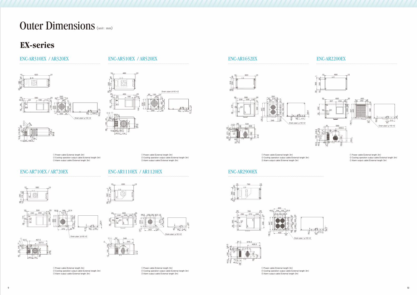
ENC-AR310EX / AR320EX ENC-AR510EX / AR520EX
ENC-AR710EX / AR720EX ENC-AR1110EX / AR1120EX
ENC-AR1652EX ENC-AR2200EX
ENC-AR2900EX
10 10620
20180
100
4040
5902532.5 53 180 114
25200
35 150 1590
200 50 159.5
30.5
9
35
9835
150
230
223
115716295
135
7
24
112
134
94.8
12.3
75.750
40
11.5 168.5134
62
①③②
Drain pipe(φ16)×2
Drain pipe(φ16)×2Drain pipe(φ16)×2
42 50 140
53
600200240 160
2525
50 53
220163
35
20
343
54852
189
189
125
111
17181155
63010 10
322
301 40
272
10
①②
③
353 35
58.5 126 126 42.5
318
311
210
17814035
(37)
Drain pipe(φ16)×2
349 3517750
59.4
40.5
35093 216 41201 149
144
160
144
61.5
162.5
162.5
61.5
(35.1)
447
440
1562015
1319
3049
250
20
3059030130230230
47330275
35
5338
308
114
19190
190
27153
26
90
56 534
62
20 70
35189126
1 2
3
53
50300
1930369
1
15 680 15
30
292
35
50
650 30327 234 89
124.1
271
44.5
63.5
190146.584.5
81 569335.5
75
40 70
29.6
190
19090
1
23
40040 292 68
16398
33
36
440
447
(36.1)
90220
39.5
60
21350
790
760
400
40035
49.5 165 165 20.5
213.7
58.2
50
290 270 200
3030
50 53
81.7
7040.775.7
678.3428.3
1515
1369
300
1950
30292
35
146.5
150
84.5
271
44.5
190
63.5
47330
60 38
39.7
447
(36.1)
440
①
③②
Drain pipe (φ16)×2
134.5134.5 160160 105.5105.5
122
122
141
141
141
41 19222
16822162
184
184
162
190
190
55
① Power cable(External length 3m)② Cooling operation output cable(External length 3m)③ Alarm output cable(External length 3m)
① Power cable(External length 3m)② Cooling operation output cable(External length 3m)③ Alarm output cable(External length 3m)
① Power cable(External length 3m)② Cooling operation output cable(External length 3m)③ Alarm output cable(External length 3m)
① Power cable(External length 3m)② Cooling operation output cable(External length 3m)③ Alarm output cable(External length 3m)
① Power cable(External length 3m)② Cooling operation output cable(External length 3m)③ Alarm output cable(External length 3m)
① Power cable(External length 3m)② Cooling operation output cable(External length 3m)③ Alarm output cable(External length 3m)
① Power cable(External length 3m)② Cooling operation output cable(External length 3m)③ Alarm output cable(External length 3m)
EX-series
Outer Dimensions(unit : mm)
9 10
931.550 12835250
11162
5795
135
85 150 1590
230
150
24
220
30 10
170
40
3118053402545025
35105
59.8
6015.8 134.7
98.5
31.5
51
91120
39
134143.5
10 480 10
①②③
223
Drain pipe(φ16)×2
134
220
332
77210
45150
182
177
35
4624025 25
200550 180
270 35
37.5127.5
52.5110
551030
175240
10 580 10
13050
41.5
50.5
50 53
Drain pipe (φ16)×2①②③ 337.5
497.552.5
145
4283
118.5
145.5 134 39134
106
325

ENC-AR310L / AR320L ENC-AR451S / AR452S ENC-AR610L / AR620L
ENC-AR1651L / AR1652LENC-AR1110L / AR1120L
ENC-AR2900L
ENC-AR2200L
30265
265
30 30405
18010 10
22.522.5 155
6-φ10(Mounting hole)
21.3
2041.3
150
217.4
450370
25
11.310
11.310
300
257.4
6-φ10(Mounting hole)
EX-seriesENC-AR310EX / AR320EX ENC-AR510EX / AR520EX ENC-AR710EX / AR720EX
ENC-AR1652EXENC-AR1110EX / AR1120EX
ENC-AR2900EX
ENC-AR2200EX
6-φ10(Mounting hole) 350
216114 20
20361
69
82168
121
79
450
27 10 329 11
30023035 35
35
730
530
165
45415
225
4510 280 10 6-φ10(Mounting hole)
30
50
30 35
465
475
510
10.510.5
354
375 12.5
2323
12.56 -φ11
(Mounting hole)
1200
550
550
730
450
20
30
428390 1919
6-φ11(Mounting hole)
45042839019
111911
640
20 30
640
50
730
1380
6-φ11(Mounting hole))
4-φ10(Mounting hole)
4-φ10(Mounting hole)
620480
10 280
45015 15
59015
25 310 285
40100
60
15
30100
250
230
170
29
4-φ10(Mounting hole)
3025
175
225
2515 10
30300 250 10
10 630 10
41272
40
12279
62
36 378 236
4-φ10(Mounting hole) 4-φ10
(Mounting hole)
620
10 40
10 40
350
330
250
15
15
380
590 15
4050320
300
400
4050
425
710
5515 15200
4 -φ10(Mounting hole)
230820
5055515
300
320
400
50405040
15
4-φ10(Mounting hole)
Diagram of Panel Cutout(unit : mm)
L-series
11 12

EX-series
ENC-AR310L / AR320L ENC-AR451S / AR452S ENC-AR610L / AR620L
ENC-AR1110L / AR1120L
ENC-AR2900L
ENC-AR1651L / AR1652L ENC-AR2200L
ENC-AR310EX / AR320EX ENC-AR510EX / AR520EX ENC-AR710EX / AR720EX
ENC-AR1110EX / AR1120EX
ENC-AR2900EX
ENC-AR1652EX ENC-AR2200EX
100
200
300
400
25 30 35 40 45 50
454535352525
60Hz50Hz
Inte
rnal
set
ting
tem
pera
ture
[ °C
]
7006005004003002001000
30 4025 35 45
454535352525
60Hz50Hz
Inte
rnal
set
ting
tem
pera
ture
[ °C
]
700
800
600
500
400
30020 25 30 35 40 45 50
253525453545
60Hz50Hz
Inte
rnal
set
ting
tem
pera
ture
[ °C
]
4540
3035302525
454035
25 30 35 40 45 50
1400
1200
1000
800
600
400
60Hz50Hz
200018001600
12001400
1000800
2520 30 35 40 45 5550
50Hz60Hz
454535352525
Inte
rnal
set
ting
tem
pera
ture
[ °C
]In
tern
al s
ettin
g te
mpe
ratu
re [
°C ]
Inte
rnal
set
ting
tem
pera
ture
[ °C
]
340030002600220018001400100060025 30 35 40 45 50 55
454535352525
50Hz60Hz
42004600
38003400300026002200180014001000
25 30 35 40 45 50 5520
454535352525
Inte
rnal
set
ting
tem
pera
ture
[ °C
]
60Hz50Hz
100
200
300
400 800
454535352525
700600500400300200
25 30 35 40 45 50
454535352525
60Hz50Hz
Inte
rnal
set
ting
tem
pera
ture
[ °C
]
Inte
rnal
set
ting
tem
pera
ture
[ °C
]
Inte
rnal
set
ting
tem
pera
ture
[ °C
]60Hz50Hz 1000
1100
500
30 40 50
25
35
25
45
35
45
900800700600
400
200300
10020 2525 30 35 40 45 50 35 45
60Hz50Hz
Inte
rnal
set
ting
tem
pera
ture
[ °C
]
Ambient temperature [ °C ]
Inte
rnal
set
ting
tem
pera
ture
[ °C
]
Inte
rnal
set
ting
tem
pera
ture
[ °C
]
4540
3035302525
4540
35
25 30 35 40 45 50
1400
1200
1000
800
600
400
60Hz50Hz
2000
1800
1600
1200
1400
1000
80025 30 35 40 4520 5550
50 Hz60 Hz
45453535
2525
3400300026002200180014001000600
2520 30 35 40 45 50 55
454535352525
50Hz60Hz
420038003400300026002200180014001000
25 30 35 40 45 50 55
454535352525
60Hz50Hz
In addition to the cooling capacitycalculation with the cooling capacity characteristic chart, it is necessary to carry out the selection procedure when using the FA cooler at an almost upper limit ambient temperature. For further information, contact Apiste sales representatives.
(unit : mm)
L-series Completely eliminating hazardous chemical substances from the standard models
The ENC-CCC Series’ standard models are completely free from the six hazardous chemical substances subjected to control in EU, and made only of materials friendly to the global environment.The display substrate is also lead-free. Thereby, the ENC-CCC Series is made entirely of environmental-friendly materials.
Operation in energy-saving mode
The ENC-CCC Series provides the intermittent operation mode that conducts air blowing operation at regular intervals, to ensure energy conservation.The fan also provides the energy-saving mode that runs in synchronization with compressor operation. Thereby the ENC-CCC Series’ models are designed with consider-ation for the global environment.
Commitment to greenhouse gas reduction
CFC gas is required for coolers.Apiste uses R-134a, because it is not subjected to control and has been proven in handling reliability and safety.“CFC Collection and Destruction Law” was reformed on October 1, 2007.Apiste intends to make efforts to reduce impact on global environment, in compliance with relevant laws and ordinances.
・ Lead (Pb)
・ Cadmium (Cd)
・ Mercury (Hg)
Hazardous chemical substances
・ Hexavalent chromium (Cr6+)
・ Polybrominated Biphenyl (PBB)
・ Polybrominated diphenyl ether (PBDE)
Cooling operation Cooling operation
Air blowing operation Air blowing operation
5 10 15 20 25 30 35 40 45 50 55 60 65 70(min)
Recently approved new refrigerant. At present, R-207c is mainly used for large-size air conditioners with 2 horsepower or more.
Mainly used for automotive air conditioners. R-134a is frequently used as refrigerant for refrigerators, in substitution for R-12.
There are wide applications in various fields. However, the complete elimination of R-22 before 2020 has been decided, and is being reduced now.
Production of R-12 was prohibited at the end of 1995, as an ozone layer depletion factor.
* The ENC-CCC Series conforms to the RoHS Directive, but is not a CE certified product.
( Note: When CFC=1)
13 14
Ozonedepletioncoefficient
Refrigerant ApplicationGreenhousecoefficient
(Note)
1 0.79R-12
0.055 0.36R-22
0 0.25R-134a
0 0.4R-407c
Diagram of Cooling Characteristics Consideration for the global environmentCo
olin
g ca
paci
ty [
W ]
Cool
ing
capa
city
[ W
]
Inte
rnal
set
ting
tem
pera
ture
[ °C
]
Ambient temperature [ °C ]
Cool
ing
capa
city
[ W
]
Cool
ing
capa
city
[ W
]
Cool
ing
capa
city
[ W
]
Cool
ing
capa
city
[ W
]
Cool
ing
capa
city
[ W
]Co
olin
g ca
paci
ty [
W ]
Cool
ing
capa
city
[ W
]
Cool
ing
capa
city
[ W
]
Cool
ing
capa
city
[ W
]
Cool
ing
capa
city
[ W
]
Cool
ing
capa
city
[ W
]
Cool
ing
capa
city
[ W
]
Ambient temperature [ °C ] Ambient temperature [ °C ] Ambient temperature [ °C ]
Ambient temperature [ °C ] Ambient temperature [ °C ] Ambient temperature [ °C ]
Ambient temperature [ °C ] Ambient temperature [ °C ]Ambient temperature [ °C ]
Ambient temperature [ °C ] Ambient temperature [ °C ]Ambient temperature [ °C ]
In addition to the cooling capacitycalculation with the cooling capacity characteristic chart, it is necessary to carry out the selection procedure when using the FA cooler at an almost upper limit ambient temperature. For further information, contact Apiste sales representatives.

L-series
Rating
MAX
Rating
MAX
Lateral-mount Type
ENC-AR310L ENC-AR320L
100V±10% 50/60Hz
3.4/3.2
3.7/3.8
7.4/7.7
290/310
330/370
200V±10% 50/60Hz
1.8/1.5
2.0/1.8
4.0/4.2
280/260
340/320
ENC-AR451S ENC-AR452S
100V±10% 50/60Hz
3.4/3.2
3.6/3.7
7.4/7.7
280/300
320/360
200V±10% 50/60Hz
1.8/1.5
2.0/1.8
4.0/4.2
280/260
340/320
ENC-AR610L ENC-AR620L
100V±10% 50/60Hz
3.3/3.2
3.9/4.1
7.4/7.7
270/310
340/370
200V±10% 50/60Hz
1.8/1.6
2.1/1.9
4.0/4.2
280/270
370/360
10 to 85% (No condensation)
HFC-134a (Non-regulated CFC)
25~45
3
Cooling operation output (Rated voltage, normally open: 250 VAC 2 A), Alarm output (Rated voltage, normally open: 250 VAC 2 A)
Panel internal temperature indicator (Also used as error display), RUN LED
Level 4 in the fast transient/burst immunity test
Approx. 59/61.5 dB
Total amplitude: 20 mm, Frequency: 300 CPM
Munsell 5Y 7/1 Equivalent color of light beige
H450×W300×D115
13kg
500/600W (50/60Hz)400/450W (50/60Hz)280/300W (50/60Hz)
H450×W350×D200
16kg
H590×W200×D200
15kg
20 to 50°C20 to 50°C
22
Approx. 63/67 dBApprox. 65/68 dB
25 to 45°C
Rating
MAX
Rating
MAX
Lateral-mount Type
ENC-AR1110L ENC-AR1120L
100V±10% 50/60Hz
5.5/4.8
6.7/6.8
15.6/14.7
450/470
620/680
200V±10% 50/60Hz
2.6/2.4
3.1/3.2
7.5/7.1
440/460
560/570
ENC-AR1651L ENC-AR1652L
100V±10% 50/60Hz
7.6/7.4
9.0/9.9
22.3/20.5
630/715
840/970
200V±10% 50/60Hz
3.4/3.6
4.3/4.6
12.7/11.6
630/720
810/910
ENC-AR2200L ENC-AR2900L
200V±10% 50/60Hz
3.4/3.2
4.4/4.1
27.0/25.0
815/950
1100/1200
200V±10% 50/60Hz
4.9/4.6
5.7/5.8
31/30
1230/1430
1570/1780
10 to 85% (No condensation)
R-407C (Non-regulated CFC)
25 to 45°C
Cooling operation output (Rated voltage, normally open: 250 VAC 2 A), Alarm output (Rated voltage, normally open: 250 VAC 2 A)
Panel internal temperature indicator (Also used as error display), RUN LED
Level 4 in the fast transient/burst immunity test
Total amplitude: 20 mm, Frequency: 300 CPM
Munsell 5Y 7/1 Equivalent color of light beige
H1000×W400×D230
38kg
2000/2200W (50/60 Hz) 2600/2900W (50/60Hz)1450/1650W (50/60Hz)950/1100W (50/60Hz)
H1380×W450×D230
57kg
H1200×W450×D230
48kg
H730×W300×D230
23kg
20 to 50°C
HFC-134a (Non-regulated CFC)
5
HFC-134a (Non-regulated CFC)
2
Approx. 70/73 dBApprox. 68/72 dBApprox. 64/68 dB
43
20 to 55°C
Specifications
EX-seriesType
Model
Cooling capacity*1
Power supply
Consumptioncurrent (A)
Starting current
Powerconsumption(MAX)*2
Ambient temperature
Ambient humidity
Coolant
Preset temperature range
No. of fan
Output
Display
Noise immunity*3
Noise
Vibration resistance
Paint color
Outer dimensions
Weight
Type
Model
Cooling capacity*1
Power supply
Consumptioncurrent (A)
Starting current
Powerconsumption(MAX)*2
Ambient temperature
Ambient humidity
Coolant
Preset temperature range
No. of fan
Output
Display
Noise immunity*3
Noise
Vibration resistance
Paint color
Outer dimensions
Weight
Type
Model
Cooling capacity*1
Power supply
Consumptioncurrent (A)
Starting current
Powerconsumption(MAX)*2
Ambient temperature
Ambient humidity
Coolant
Preset temperature range
No. of fan
Output
Display
Noise immunity*3
Noise
Vibration resistance
Paint color
Outer dimensions
Weight
Rating
MAX
Rating
MAX
Top-mount Type
ENC-AR310EX ENC-AR320EX
100V±10% 50/60Hz
3.4/3.2
4.0/4.2
7.4/7.7
290/310
360/410
200V±10% 50/60Hz
1.8/1.5
1.9/1.7
4.0/4.2
280/265
340/330
ENC-AR510EX ENC-AR520EX
100V±10% 50/60Hz
3.3/3.0
3.6/3.9
7.4/7.7
270/280
320/360
200V±10% 50/60Hz
1.9/1.4
2.0/1.8
4.0/4.2
280/260
360/320
ENC-AR710EX ENC-AR720EX
100V±10% 50/60Hz
3.2/3.3
3.9/4.1
7.4/7.7
250/300
350/390
200V±10% 50/60Hz
1.9/1.4
2.0/1.8
4.0/4.2
285/265
340/350
10 to 85% (No condensation)
HFC-134a (Non-regulated CFC)
25 to 45°C
Cooling operation output (Rated voltage, normally open: 250 VAC 2 A), Alarm output (Rated voltage, normally open: 250 VAC 2 A)
Panel internal temperature indicator (Also used as error display), RUN LED
Level 4 in the fast transient/burst immunity test
Total amplitude: 20 mm, Frequency: 300 CPM
Munsell 5Y 7/1 Equivalent color of light beige
H230×W450×D250
15kg
600/700 (50/60Hz)450/500 (50/60Hz)280/300 (50/60 Hz)
H333×W550×D270
22kg
H230×W590×D200
16kg
20 to 50°C
2
Approx. 62/65 dB
Rating
MAX
Rating
MAX
Top-mount Type
100V±10% 50/60Hz
5.4/4.8
6.3/6.6
15.6/14.7
440/470
570/630
200V±10% 50/60Hz
2.7/2.4
3.2/3.3
7.5/7.1
440/470
570/630
10 to 85% (No condensation)
R-407C (Non-regulated CFC)
25 to 45°C
Cooling operation output (Rated voltage, normally open: 250 VAC 2 A), Alarm output (Rated voltage, normally open: 250 VAC 2 A)
Panel internal temperature indicator (Also used as error display), RUN LED
Level 4 in the fast transient/burst immunity test
2600/2900(50/60 Hz)1900/2200(50/60 Hz)1500/1650(50/60 Hz)950/1100(50/60 Hz)
H447×W760×D400
57kg
H447×W650×D400
48kg
H448×W590×D350
33kg
H318×W600×D353
27kg
20 to 50°C
HFC-134a (Non-regulated CFC) HFC-134a (Non-regulated CFC)
2
Approx. 65/68 dB Approx. 70/71 dB Approx. 72/73 dBApprox. 60/65 dB
3 2 5
20 to 55°C
The rated capacity value with an ambient temperature of 35°C and a preset panel internal temperature of 35°C.(Measurement condition: JIS-C-9612 air-enthalpy method)The rated value is measured under an ambient temperature of 35°C and an ambient humidity of 40%. The maximum value is measured under the highest allowable ambient temperature and an ambient humidity of 40%.Determined by the standards of the control PCB.
*1 :
*2 :*3 :
Approx. 60/65 dB
15 16
Single-phase Single-phase Single-phase Single-phase Single-phase Single-phase Single-phase
Single-phase Single-phase Single-phase Single-phase Three-phase Three-phaseSingle-phase Single-phase Single-phase Three-phase Three-phase
Single-phase Single-phase Single-phase Single-phase Single-phase
Type
Model
Cooling capacity*1
Power supply
Consumptioncurrent (A)
Starting current
Powerconsumption(MAX)*2
Ambient temperature
Ambient humidity
Coolant
Preset temperature range
No. of fan
Output
Display
Noise immunity*3
Noise
Vibration resistance
Paint color
Outer dimensions
Weight
200V±10% 50/60Hz
3.4/3.5
4.4/4.5
12.7/11.6
610/690
810/890
200V±10% 50/60Hz
3.3/3.2
4.2/4.1
27/25
850/1050
1050/1250
200V±10% 50/60Hz
4.8/4.7
5.7/5.8
31/30
1270/1450
1700/1900
Total amplitude: 20 mm, Frequency: 300 CPM
Munsell 5Y 7/1 Equivalent color of light beige
ENC-AR1110EX ENC-AR1120EX ENC-AR1652EX ENC-AR2200EX ENC-AR2900EX

2
Advancement of Factory Automation and control devices
As automation advances, FA* has contributed to a sophisticated production system that deals with diversification and customization, which are the demands of the time. As a result, the concept of control has also greatly changed.
When FA increases dependence on control systems, other challenges arise. The first is that the environment of control devices becomes more important for risk management in the factory. The second contradicts the above issue that the current FA environment is not suitable for control devices.
Panel air-conditioners are rapidly becoming widespread. The reason why required・・・
Increased dependence on control systems andmore expense for control devices
3 Semiconductor / electronics components are easilyaffected by heat, moisture and dust.
Data has proven that heat and moisture greatly increase the failure rate of semiconductor and electronics components and shorten their operating life.
The phenomenon called "3K alienation" (trend in the labor market in Japan in which people do not want to do jobs that can be characterized by three Japanese words starting with "k": "kiken (danger)", "kitanai(dirty)", and "kitsui (hard)") is continuing even today when job shortages are a societal concern. In order to solve this problem, factories promote the automation of the production process by using robots or automatic
machinery, resulting in a steady increase in the use of control devices. Consequently, in more and more cases, a centralized control system is established on a mezzanine added to the factory, from which workers manage a control panel consisting of several control devices.
Tendency to suffer greater damage from the failure of control devicesThe integrated production line and highly systematized production in a factory involves the risk of a failure or breakdown of a single process affecting the operation of the entire factory. Since the control system is a vital part of FA, even the breakdown of a single control device may cause
significant damage. In other words, we must understand that the reliability of the control devices is an extremely important issue.
Factory environment unsuitable for control devicesFurthermore, the advancement of the integrated production line results in an environment hostile to certain devices such as an assembly robot operating near a heat-treatment process. Such factory environments are detrimental to multi-functional, sophisticated control devices. Semicon-
ductor and electronics components used as the core of those control devices are easily affected by heat, moisture and dust.
In the past, there were several factories (processes) specializing in a certain process, such as heat treatment, working, or assembly. In new FA systems, however, these factories (processes) are integrated into a single production line system including upstream and downstream processes. Production systems,such as FMS*, have become more advanced. It is natural that people will request a flexible and intelligent control system with advanced, multi-functional control devices.
The advancement of FA promotes an increase in control devices and sophisticated control. It can be said that the development of FA was achieved by increased dependence on control systems.
*FA: Factory Automation*FMS: Flexible Manufacturing System
Advanced automation and the increase in control devices
Proliferation of integrated production line and advanced control systems
Temperature inside the control panel for a metal working line of an automotive manufacturer (From spring to summer)
Temperatureinside the controlpanel (℃)
Test facility: Combined punching machineExternal air-conditioner: (Provided) 25 to 27℃Cooling method inside the panel: Axial fanSize of control panel:1800 (H) × 1000 (W) × 450 (D) mmContained devices:NC device, AC servo and other devicesmeasured points: 6 pointsTime of measurement: 3:00 p.m.
Temperature inside and outside the power control panel of an automotive manufacturer
Test facility: Metal working line for automotive partsExternal air-conditioner: Not providedCooling method inside the panel: General-purpose heat exchangerSize of control panel: 2000 (H) × 1000 (W) × 500 (D) mmContained devices: 3-axis AC servo and other devicesMeasured points: 1 point at the center of the panel
17 18
1

The graph on the right shows 'the relationship between the temperature and acceleration of semiconductor failure*. The Y axis shows the accelera-tion of the failure. At a temperature of 25℃, the failure rate is less than 0. At 40℃, the failure rate is 1. The ratio, however, increases to 10 to 30 times at 60℃, and jumps to 100 to 300 times at 80℃. This graph clearly shows that an increase in temperature greatly affects the failure rate of semiconductor/electronics components.
Heat accelerates the failure rate of semiconductor / electronics components
Ambient temperature vs. failure rate of semiconductor
The next graph shows "the relationship between the temperature and the life of a capacitor". At a temperature of 30℃, the life of a capacitor is about 80,000 hours. At 40℃, the life becomes 40,000 hours, it means about half the life at 30℃: At 60℃, the life is further shortened to about 10,000 hours.Heat also greatly affects the life of semiconductor/electronics components.
Heat dramatically shortens the life of semiconductor / electronics components
Ambient temperature vs. life of an electro-lytic capacitor
Control devices have a lot of joints and moisture is one of the greatest enemies of these joints. The graph on the right shows “the relationship between corrosion and relative humidity”. You can see that corrosion rapidly advances when humidity exceeds 60%. Since humidity around 70% is a normal level in Japan, measures against moisture are crucial for control devices. Furthermore, corrosion advances more rapidly at higher temperatures, so the measures against moisture must be considered along with the measures against heat.
In conclusion, we should review the approach to the environment for control devices from the beginning. For example, when a control panel is instaled on the mezzanine of the factory as described earlier, the tempera-ture on the mezzanine is usually higher than the ground surface by 5℃. In summer in particular, the temperature becomes extremely high due to the heat from the factory roof. Needless to say, such an environment is the worst for control devices using many semiconductor/electronics components. Although the manufacturers of control devices continue efforts to enhance the heat resistance of their products, there is a limit. You require drastic measures to solve the problem. In addition to temperature and moisture, dust and oil mist are also known as serious problems to control devices. In some cases, chemical absorption agents are installed in the control panels, but these are only a band-aid-like solution. This problem must be taken seriously along with the measures against heat and moisture.
Destructive influence of moisture on control devices
Relative humidity vs. formation of rust
Axial fan
Spot type air-conditioner
What happens to the production activity when control devices suffer a breakdown? Possible results are as follows:
Assume that one control panel suffers a breakdown. Even if the breakdown lasts for only 30 minutes, the previous and next production processes also stop because of interlocks of the integrated and systematized production line. If a device such as a furnace stops, It takes at least one or two hours to
recover normal operation. As a result, the failure of a single control panel will stop the operation of the previous and next lines, resulting in a time loss of about two hours.
Tremendous loss of time
The cost of replacing an inverter is expected to be about ¥300,000 for a 30 kW inverter. Replacing only a PC board will cost about ¥60,000. Moreover, ordering a necessary part requires at least two to three weeks. If you plan to have the inverter in stock, another ¥300,000 is required. Assigning mainte-nance staff to find faiures at an early stage requires the cost of “(Hourly-wage) × (Working hours) × (No. of people)”. At any rate, you have to be
prepared to pay a considerable cost.What is the best way to solve these problems at their source? After all, these problems can be considered to be an environmental problem of the integrated control devices or control panel.
Significant loss of cost
In production sites, various measures have been taken against these problems for a long time. Such measures, however, were insufficient to solve these problems at their source. The following is a brief explanation and the drawbacks of such measures
Axial fans are often instated inside control panels to prevent control devices from heating up. This is,however, far from an ideal solution. Since axial fans take in outside air indirectly, they cannot prevent the ingress of oil mist
or dust in the factory air. The cooling ability may be totally insufficient because it depends on the temperature of the outside air.
Axial fan
Spot type air-conditioners are also often used as a method to cool the inside of control panels. They are,however, originally designed for home use, not for the control panels in factories. Therefore, the air is not completely separated from outside air, resulting in contamination with oil mist or dust. Spot type air-conditioners are not suitable for cooling the inside of control panels either.
Another method is to install several control panels in a control room with an air-conditioner The potential problems are: It is difficult to find the space for the room;construction requires considerable cost: and it is difficult to change the layout when the production system is changed. Dust may be another problem because many people go in/out of the room.
After reviewing these issues, the best measure for maintaining the proper environment for control panels is finally found: a panel air-conditioner, or an air-conditioner specially designed for a control panel. Apiste and some innovative. FA-related parties are the first to focus attention on such air- conditioners.
Spot type air-conditioner
Air-conditioned control room
Note : This graph was prepared based on Arrhenius’law that predicts the life of a semiconductor(1.2eV) under the stress of heat.
Note : This graph was prepared based on the data for an electrolytic capacitor with heat-resistant characteris-tics at 85℃ for 20,000 hours.
Note : This graph was prepared based on the data for rust formation when an iron plate is exposed to the air with moisture.
19 20
Influence of control device breakdown4
5 Conventional measures for maintainingthe proper environment for a control panel

Panel air-conditioners are rapidly becomingwidespread.Why and what functionsand performance are required?
Apiste is a manufacturer specializing in panel air-conditioners. We have been working to understand the realities of production sites and the environment of control devices, and to identify problems and solutions from the standpoint of specialists. These efforts have led to the development
of various Apiste panel air-conditioners,of which details are provided in this catalog. The basic concept is to provide measures against "heat", "moisture", and "dust".
Temperature inside and outside the control panel of an automotive manufacturer after an FA air-conditioner is installed
Conditions:ENC-720EX1500 (H)x800 (W)x400 (D) mmContained devices:Sequencer, transformer, and othercontrollers for measurement
Panel air-conditioners have a separate air circulation structure to prevent oil mist or dust in a factory from entering the control panel. Their internal air circulation system circulates air only inside the control panel for cooling and dehumidifying the air.
They actively cool and dehumidify the air and prevent dust from entering the control panel by establishing independent air circulation inside the control panel. Thus, all measures against heat, moisture, and dust are implemented. This is the first achievement of an ideal environment for control devices using semiconductor/electronics components in a hostile
production atmosphere. This fact has become the focus of attention of FA-related parties. Panel air-conditioners are being recognized as necessities in the FA environment.
Structure of FA air-conditioners
Panel air-conditioners feature various measures against moisture and condensation as well as gradual cooling.
Conditions for the occurrence of condensation
Humidity trend after installation of panel air-conditioner
Structure of FA air-conditioners o�er various functions in addition to cooling the air.
21 22
time(h)
humid(%) 20
30
40
50
60
70
80
3 421
Power ON
[Condition]targetpanel sizeinner deviceA/C model
: NC machine: H2000 × W1200 × D2600: NC serve driver(3axis): ENC-AR720EX
1
3
Against heat Keeping the temperature inside the controlpanel constant
Against moisture Dehumidification to prevent condensation2 Against dust Separate air circulation shutting the outside air out of the panel
Panel air-conditioner providing measures against "heat","moisture", and "dust"
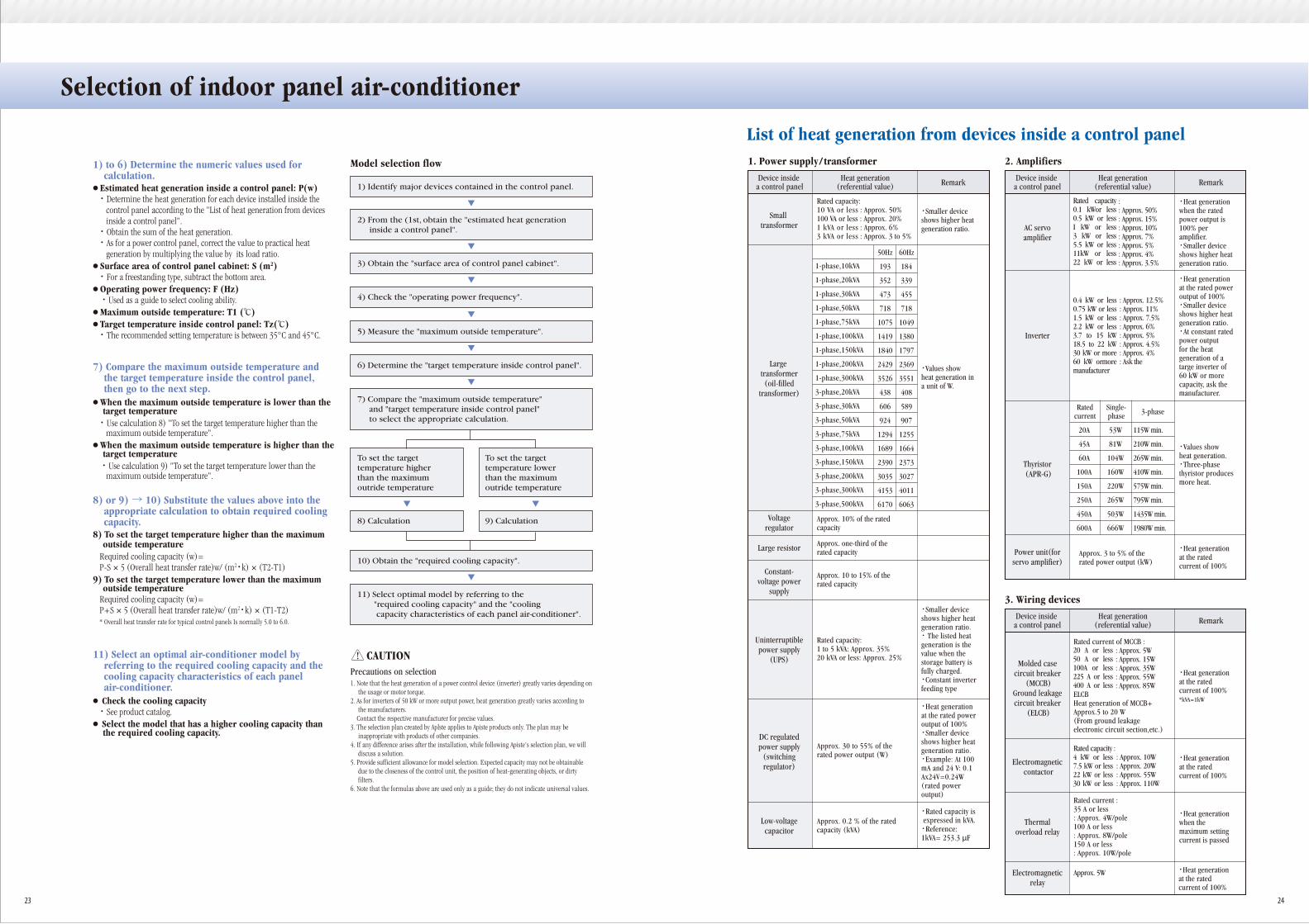
1) to 6) Determine the numeric values used for calculation.
● Estimated heat generation inside a control panel: P(w)・ Determine the heat generation for each device installed inside the
control panel according to the "List of heat generation from devices inside a control panel".・ Obtain the sum of the heat generation.・ As for a power control panel, correct the value to practical heat
generation by multiplying the value by its load ratio.● Surface area of control panel cabinet: S (m2)・ For a freestanding type, subtract the bottom area.● Operating power frequency: F (Hz)
・ Used as a guide to select cooling ability.● Maximum outside temperature: T1 (℃)● Target temperature inside control panel: Tz(℃)・ The recommended setting temperature is between 35°C and 45°C.
7) Compare the maximum outside temperature and the target temperature inside the control panel, then go to the next step.
● When the maximum outside temperature is lower than the target temperature・ Use calculation 8) "To set the target temperature higher than the
maximum outside temperature".● When the maximum outside temperature is higher than the
target temperature ・ Use calculation 9) "To set the target temperature lower than the
maximum outside temperature".
8) or 9) → 10) Substitute the values above into the appropriate calculation to obtain required cooling capacity.
8) To set the target temperature higher than the maximum outside temperature
Required cooling capacity (w)=P-S × 5 (Overall heat transfer rate)w/ (m2・k) × (T2-T1)
9) To set the target temperature lower than the maximum outside temperature
Required cooling capacity (w)=P+S × 5 (Overall heat transfer rate)w/ (m2・k) × (T1-T2)* Overall heat transfer rate for typical control panels Is normally 5.0 to 6.0.
11) Select an optimal air-conditioner model by referring to the required cooling capacity and the cooling capacity characteristics of each panel air-conditioner.
● Check the cooling capacity・ See product catalog.● Select the model that has a higher cooling capacity than
the required cooling capacity.
1. Note that the heat generation of a power control device (inverter) greatly varies depending on the usage or motor torque.
2. As for inverters of 50 kW or more output power, heat generation greatly varies according to the manufacturers.
Contact the respective manufacturer for precise values.3. The selection plan created by Aplste applies to Apiste products only. The plan may be
inappropriate with products of other companies.4. If any difference arises after the installation, while following Apiste's selection plan, we will
discuss a solution.5. Provide sufficient allowance for model selection. Expected capacity may not be obtainable
due to the closeness of the control unit, the position of heat-generating objects, or dirty filters.
6. Note that the formulas above are used only as a guide; they do not indicate universal values.
List of heat generation from devices inside a control panel1. Power supply / transformerModel selection flow
Precautions on selection
CAUTION
1) Identify major devices contained in the control panel.
3) Obtain the "surface area of control panel cabinet".
2) From the (1st, obtain the "estimated heat generation inside a control panel".
4) Check the "operating power frequency".
5) Measure the "maximum outside temperature".
6) Determine the "target temperature inside control panel".
10) Obtain the "required cooling capacity".
8) Calculation 9) Calculation
7) Compare the "maximum outside temperature" and "target temperature inside control panel" to select the appropriate calculation.
To set the targettemperature higherthan the maximumoutride temperature
To set the targettemperature lowerthan the maximumoutride temperature
11) Select optimal model by referring to the "required cooling capacity" and the "cooling capacity characteristics of each panel air-conditioner".
Device inside a control panel
Heat generation(referential value) Remark
Rated capacity:10 VA or less : Approx. 50%100 VA or less : Approx. 20%1 kVA or less : Approx. 6%3 kVA or less : Approx. 3 to 5%
Approx. 10% of the ratedcapacity
Approx. 10 to 15% of therated capacity
Approx. one-third of therated capacity
1-phase,10kVA
1-phase,20kVA
1-phase,30kVA
1-phase,50kVA
1-phase,75kVA
1-phase,100kVA
1-phase,150kVA
1-phase,200kVA
1-phase,300kVA
3-phase,20kVA
3-phase,30kVA
3-phase,50kVA
3-phase,75kVA
3-phase,100kVA
3-phase,150kVA
3-phase,200kVA
3-phase,300kVA
3-phase,500kVA
Small transformer AC servo
amplifier
Large transformer(oil-filled
transformer)
Voltageregulator
Large resistor
Constant-voltage power
supply
DC regulatedpower supply
(switchingregulator)
Uninterruptiblepower supply
(UPS)
・Smaller deviceshows higher heatgeneration ratio.
・Values showheat generation ina unit of W.
2. Amplifiers
50Hz
193
352
473
718
1075
1419
1840
2429
3526
438
606
924
1294
1689
2390
3035
4153
6170
60Hz
184
339
455
718
1049
1380
1797
2369
3551
408
589
907
1255
1664
2373
3027
4011
6063
・Smaller deviceshows higher heatgeneration ratio.・ The listed heatgeneration is thevalue when thestorage battery isfully charged.・Constant inverterfeeding type
Rated capacity:1 to 5 kVA: Approx. 35%20 kVA or less: Approx. 25%
Approx. 30 to 55% of therated power output (W)
Approx. 3 to 5% of therated power output (kW)
・Heat generationat the rated poweroutput of 100%・Smaller deviceshows higher heatgeneration ratio.・Example: At 100mA and 24 V: 0.1Ax24V=0.24W(rated poweroutput)
Low-voltagecapacitor
Approx. 0.2 % of the ratedcapacity (kVA)
・Rated capacity is expressed in kVA.・Reference:1kVA= 253.3 μF
Device inside a control panel
Heat generation(referential value) Remark
:: Approx. 50%: Approx. 15%: Approx. 10%: Approx. 7%: Approx. 5%: Approx. 4%: Approx. 3.5%
・Heat generationwhen the ratedpower output is100% peramplifier.・Smaller deviceshows higher heatgeneration ratio.
Inverter
: Approx. 12.5%: Approx. 11%: Approx. 7.5%: Approx. 6%: Approx. 5%: Approx. 4.5%: Approx. 4%: Ask the
Thyristor (APR-G)
20A
45A
60A
100A
150A
250A
450A
600A
53W
81W
104W
160W
220W
265W
503W
666W
115W min.
210W min.
265W min.
410W min.
575W min.
795W min.
1435W min.
1980W min.
Power unit(forservo amplifier)
・Heat generationat the ratedcurrent of 100%
Ratedcurrent
Single-phase 3-phase
・Heat generationat the rated poweroutput of 100%・Smaller deviceshows higher heatgeneration ratio.・At constant ratedpower outputfor the heatgeneration of atarge inverter of60 kW or morecapacity, ask themanufacturer.
・Values showheat generation.・Three-phasethyristor producesmore heat.
Molded casecircuit breaker
(MCCB)Ground leakagecircuit breaker
(ELCB)
3. Wiring devices
Device inside a control panel
Heat generation(referential value) Remark
: Approx. 5W: Approx. 15W: Approx. 35W: Approx. 55W: Approx. 85W
・Heat generationat the ratedcurrent of 100%*kVA=1kW
・Heat generationat the ratedcurrent of 100%
Electromagnetic contactor
Thermaloverload relay
Electromagneticrelay
Rated current of MCCB :
ELCBHeat generation of MCCB+Approx.5 to 20 W(From ground leakageelectronic circuit section,etc.)
: Approx. 10W: Approx. 20W: Approx. 55W: Approx. 110W
Rated capacity :
Rated current :35 A or less: Approx. 4W/pole100 A or less: Approx. 8W/pole150 A or less: Approx. 10W/pole
Approx. 5W
・Heat generationwhen themaximum settingcurrent is passed
・Heat generationat the ratedcurrent of 100%
23 24
Rated capacity0.1 kWor less0.5 kW or lessI kW or less3 kW or less5.5 kW or less11kW or less22 kW or less
0.4 kW or less0.75 kW or less1.5 kW or less2.2 kW or less3.7 to 15 kW18.5 to 22 kW30 kW or more60 kW ormoremanufacturer
4 kW or less7.5 kW or less22 kW or less30 kW or less
20 A or less50 A or less100A or less225 A or less400 A or less
Selection of indoor panel air-conditioner

Panel air-conditioners are rapidly becomingwidespread.Why and what functionsand performance are required?
4. Control devices
Device inside a control panel
Heat generation(referential value) Remark
Approx. 1 W to 2 W/device
Approx. [Operating current × 1.5(W)]
Small relay
Solid-state relay(SSC, SSR)
Size 48 × 96: Approx. 5 WSize 96 × 96: Approx. 10 W
Temperatureregulator
Approx. 3% of currentconsumptionSequencer
Approx. 60 W to 130 W/deviceCRT (Monitor)
10 to 20 MB: Approx. 100 WHard disk drive
Drive for two 3.5- or 5 1/4-Inchfloppy disks: Approx. 20 W
Floppy diskdrive
capacity
・Large-sizemonitor (more inches)generates more heat.
・Including thepower supply unit
・General- purposeAC axial flowmotor
5. Computer-related devices
Device inside a control panel
Heat generation(referential value) Remark
100 W to 300 W/devicePersonal computer(factory computer)
・At 100% controltorque and 5%brake frequencyMainly used as abrake for a motor
7. Motor control devices
Containeddevices
Heat generation(referential value) Remark
Rated capacity: 3.7kW : 0.19 kW 5.5kW : 0.28 kW 7.5kW : 0.38 kW 1 1 kW : 0.55 kW 1 5 kW : 0.75 kW 1 8 kW : 0.93 kW 2 2 kW : 1.1 kW 3 0 kW : 1.5 kW 3 7 kW : 1.9 kW 4 5 kW : 2.3 kW 5 5 kW : 2.8 kW 7 5 kW : 3.8 kW 9 0 kW : 4.5 kW110kW : 5.5 kW
200 V-class,Device
Including Inverter
Control resistorControl unit
・At 100% controltorque and 5%brake frequencyMainly used as abrake for a motor
Rated capacity: 3.7kW : 0.19 kW 5.5kW : 0.28 kW 7.5kW : 0.38 kW 1 1 kW : 0.55 kW 1 5 kW : 0.75 kW 1 8 kW : 0.93 kW 2 2 kW : 1.1 kW 3 0 kW : 1.5 kW 3 7 kW : 1.9 kW 4 5 kW : 2.3 kW 5 5 kW : 2.8 kW 7 5 kW : 3.8 kW 9 0 kW : 4.5 kW110kW : 5.5 kW
400 V-class,Device
Including Inverter
Control resistorControl unit
6. Other
Device inside a control panel
Heat generation(referential value) Remark
Size 90 × 90: Approx. 10 WSize 120 × 120:Approx. 15 to 20 WSize 160 × 160:Approx. 40 to 50 W
Fan motor
・Typical valueAsk respectivemanufacturer fordetails.
7. Motor control devices
Containeddevices
Heat generation(referential value) Remark
Rated capacity:22 kW: 742 W30 kW: 1052W37 kW: 1820W
Rated capacity:22 kW: 770W30 kW: 1090W37 kW: 1260 W45 kW: 1560W55 kW: 1840W
200 V-class,large AC servo
amplifier
400 V-class,large AC servo
amplifier
*Ask respective manufacturer for details of an inverter.
Use the following table to select the breaker capacity
・Input voltage:50 HzVoltage balance:0%Motor toad: 100%Typical value
7. Motor control devices Selecting a breaker
When using an air-conditioner with a 400V powersupply, use the following table to select the capacity ofa transformer
Selecting a transformer
Containeddevices
Heat generation(referential value) Remark
3.7 kW: 10.1 W5.5 kW: 17.2 W7.5 kW: 18.8 W1 1 kW: 20.2 W15 kW: 28.6 W22 kW: 33.3 W30 kW: 39.3 W37 kW: 70.8 W45 kW: 47.1 W55 kW: 55.1 W75 kW: 65.1 W90 kW: 75.5 W110kW: 83.4 W
200 V-class,AC reactor
・Input voltage:50 HzVoltage balance:0%Motor load: 100%Generation lossmay varydepending on thecapacity andtorque of powersupply.According toG7/P7 invertermanufactured byFUJI DENKI.Typical value
3.7 kW: 7.6 W5.5 kW: 10.9 W17.5 kW: 12.8 W11 kW: 14.3W15 kW: 18.5W18.5 kW: 26.9 W22 kW: 35.6W30 kW: 38.9 W37 kW: 50.2 W45 kW: 55.7 W55 kW: 66.3 W75 kW: 70.7 W90 kW: 85.5 W110 kW: 93.5W132 kW: 119W160kW: 135W200kW: 155W220kW: 170W280kW: 210W
400 V-class,AC reactor
Power Supply Applicable capacity of a breaker (Unit: A)
More than the maximum current consumption of thepanel air-conditioner to be used
Single-phase,100 V
More than the maximum current consumption of thepanel air-conditioner to be used
Single-phase,200 V
More than the maximum current consumption of thepanel air-conditioner to be used
3-phase,200 V
Power Supply Calculation to obtain the capacity of a transformer(Unlt: VA)
100 V x [Starting current of the panel air-conditioner(A)]
Single-phase,100 V
100 V x [Starting current of the panel air-conditioner(A)]
Single-phase,200 V
100 V x [Starting current of the panel-air conditioner(A)]
3-phase,200 V
*Ask respective manufacturer for other devices.
Note: This material is prepared by adding Apiste's original research results to the material provided by the technical study group of heat-related devices for control panels. The heat generation values described here are typical values. Ask respective manufacturers for precise values.
*Note: √3=1.732
25 26
①
②
・At 100% controltorque and 5%brake frequencyMainly used as abrake for a motor
7. Motor control devices
Containeddevices
Heat generation(referential value) Remark
Rated capacity: 30kW : 1.3kW 37kW : 1.6kW 45kW : 2.0kW 55kW : 2.3kW 75kW : 3.1kW 90kW : 3.7kW110kW : 4.4kW
400 V-class,large inverter
・At 100% controltorque and 5%brake frequencyMainly used as abrake for a motor
Rated capacity: 30kW : 1.2kW 37kW : 1.4kW 45kW : 1.7kW 55kW : 1.9kW 75kW : 2.6kW 90kW : 3.0kW110kW : 3.3kW132kW : 4.1kW160kW : 5.0kW200kW : 6.0kW220kW : 6.8kW280kW : 8.2kW
400 V-class,Device
Including Inverter
Control resistorControl unit
③
④