FLUID COOLERS
34
INNOVATIVE HEAT TRANSFER PRODUCTS FLUID COOLERS INSTALLATION AND OPERATING MANUAL A SINGLE SOURCE FOR ALL YOUR COIL NEEDS AND CUSTOM ENGINEERED HEAT TRANSFER PRODUCT
Transcript of FLUID COOLERS
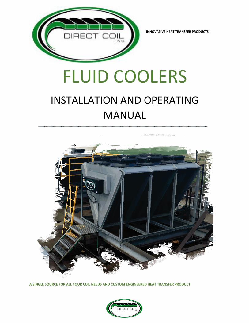
INNOVATIVE HEAT TRANSFER PRODUCTS
FLUID COOLERS INSTALLATION AND OPERATING
MANUAL
A SINGLE SOURCE FOR ALL YOUR COIL NEEDS AND CUSTOM ENGINEERED HEAT TRANSFER PRODUCT

1
Contents 1.0 INTRODUCTION ....................................................................................................................................... 1
1.1 RECIEVING & INSPECTION ................................................................................................................... 1
1.2 UNIT NOMENCLATURE ........................................................................................................................ 1
1.3 STANDARD FEATURES ......................................................................................................................... 1
1.4 UNIT PARAMETERS ............................................................................................................................. 2
1.5 UNIT ELECTRICAL DATA ....................................................................................................................... 5
1.6 TYPICAL WIRING SCHEMATICS ............................................................................................................ 7
1.7 DIMENSIONAL DRAWINGS ................................................................................................................ 11
2.0 INSTALLATION ....................................................................................................................................... 17
2.1 SITE SELECTION ................................................................................................................................. 17
2.2 LIFTING INSTRUCTIONS ..................................................................................................................... 19
2.4 START UP ........................................................................................................................................... 20
2.5 PIPING SCHEMATICS ......................................................................................................................... 20
3.0 MAINTENANCE ...................................................................................................................................... 21
3.1 HEAT EXCHANGER CLEANING ........................................................................................................... 21
3.2 TROUBLESHOOTING & RECOMMENDATIONS .................................................................................. 23
4.0 ADIABATIC COOLING SYSTEM ............................................................................................................... 25
4.1 INSTALLATION ................................................................................................................................... 25
4.2 MAINTENANCE .................................................................................................................................. 25
PRODUCT SUPPORT .................................................................................................................................... 28
PRODUCT WARRANTY ................................................................................................................................. 29
1
1.0 INTRODUCTION
1.1 RECIEVING & INSPECTION Congratulations on purchasing your brand-new Direct Coil Unit, which has been thoroughly inspected and leak tested before shipment to
ensure peak performance as promised. Upon arrival of your system, carefully check that all parts of the shipment are present and visually
inspect for any damages. If any shortages or damages are noticed, report to the delivering carrier before signing the delivery forms. Direct Coil
Inc. is not responsible for any issues that occur while the package is in transit. At this time, you should also check and ensure that all electrical
components are in place. Always keep the unit in a dry and safe storage area after delivery, before the installation.
The installation and maintenance of your unit must always be performed by qualified personnel, who have the experience and knowledge of
local codes and regulations to carry out the processes in a safe and acceptable manner.
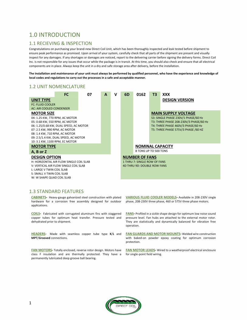
1.2 UNIT NOMENCLATURE
1.3 STANDARD FEATURES CABINETS- Heavy-gauge galvanized steel construction with plated hardware for a corrosion free assembly designed for outdoor applications.
VARIOUS FLUID COOLER MODELS- Available in 208-230V single phase, 208-230V three phase, 460 or 575V three phase motors.
COILS- Fabricated with corrugated aluminum fins with staggered copper tubes for optimum heat transfer. Pressure tested and dehydrated prior to shipment.
FANS- Profiled in a sickle shape design for optimum low noise sound pressure level. Fan hubs are attached to the external motor rotor. They are statistically and dynamically balanced for vibration free operation.
HEADERS- Made with seamless copper tube type K/L and MPT/Grooved connections.
FAN GUARDS AND MOTOR MOUNTS- Welded wire construction with baked-on powder epoxy coating for optimum corrosion protection.
FAN MOTORS- Totally enclosed, reverse rotor design. Motors have class F insulation and are thermally protected. They have a permanently lubricated deep groove ball bearing.
FAN MOTOR LEADS- Wired to a weatherproof electrical enclosure for single-point field wiring.
FC 07 A V 6D 0162 T3 XXX UNIT TYPE FC: FLUID COOLER AC: AIR COOLED CONDENSER
DESIGN VERSION
MOTOR SIZE 04: 1.25 KW, 770 RPM, AC MOTOR 05: 0.68 KW, 550 RPM, AC MOTOR 06: 1.25/0.68 KW, DUAL SPEED, AC MOTOR 07: 2.5 KW, 990 RPM, AC MOTOR 08: 1.4 KW, 710 RPM, AC MOTOR 09: 2.5/1.4 KW, DUAL SPEED, AC MOTOR 10: 3.1 KW, 1100 RPM, EC MOTOR
MAIN SUPPLY VOLTAGE S3: SINGLE PHASE 230V/1 PHASE/60 Hz T3: THREE PHASE 208-230V/3 PHASE/60 Hz T4: THREE PHASE 460V/3 PHASE/60 Hz T5: THREE PHASE 575V/3 PHASE /60 HZ
MOTOR TYPE A, B or Z
NOMINAL CAPACITY 8 TONS UP TO 500 TONS
DESIGN OPTION H: HORIZONTAL AIR FLOW SINGLE COIL SLAB V: VERTICAL AIR FLOW SINGLE COIL SLAB L: LARGE V TWIN COIL SLAB S: SMALL V TWIN COIL SLAB W: W SHAPE QUAD COIL SLAB
NUMBER OF FANS 1 THRU 7: SINGLE ROW OF FANS 4D THRU 9D: DOUBLE ROW FANS

PARAMETERS
2
1.4 UNIT PARAMETERS
MODEL NO. FAN
CONFIG FPI
550 RPM "05"
SOUND LEVEL
Dba (1)
770 RPM "04"
SOUND LEVEL
Dba (1)
710 RPM "08"
SOUND LEVEL
Dba (1)
990 RPM "07" SOUND LEVEL Dba
(1)
1100 RPM "10"
SOUND LEVEL
Dba (1)
INTERNAL VOLUME
US GALLON
APPROX DRY SHIPPING
WEIGHT LBS
SINGLE ROW UNITS
FC**A(V)(H)1010 1X1 9 43 51 50 57 58 3.4 520
FC**A(V)(H)1012 1X1 12 43 51 50 57 58 3.4 535
FC**A(V)(H)1015 1X1 12 43 51 50 57 58 5.1 585
FC**A(V)(H)1018 1X1 12 43 51 50 57 58 6.8 650
FC**A(V)(H)2024 1X2 12 46 54 53 60 61 6.8 845
FC**A(V)(H)2029 1X2 12 46 54 53 60 61 10.2 962
FC**A(V)(H)2035 1X2 12 46 54 53 60 61 13.6 1085
FC**A(V)(H)3038 1X3 9 47 55 54 61 62 15.3 1250
FC**A(V)(H)3046 1X3 12 47 55 54 61 62 15.3 1320
FC**A(V)(H)3051 1X3 12 47 55 54 61 62 20.4 1480
FC**A(V)(H)4063 1X4 12 48 56 55 62 63 20.4 1775
FC**A(V)(H)4071 1X4 12 48 56 55 62 63 27.2 1990
FC**A(V)(H)5080 1X5 12 49 57 56 63 64 25.3 2430
FC**A(V)(H)5089 1X5 12 49 57 56 63 64 33.9 2705
FC**A(V)(H)6098 1X6 12 50 58 57 64 65 30.4 2965
FC**A(V)(H)6108 1X6 12 50 58 57 64 65 40.7 3290
FC**A(V)(H)7116 1X7 12 51 59 58 65 66 35.5 3405
FC**A(V)(H)7127 1X7 12 51 59 58 65 66 47.5 3785
DOUBLE ROW UNITS
FC**A(V)(H)2D048 2X2 12 48 56 55 62 63 13.6 1535
FC**A(V)(H)2D058 2X2 12 48 56 55 62 63 20.4 1750
FC**A(V)(H)2D070 2X2 12 48 56 55 62 63 27.2 1965
FC**A(V)(H)3D076 2X3 9 50 58 57 64 65 30.4 2370
FC**A(V)(H)3D092 2X3 12 50 58 57 64 65 30.4 2490
FC**A(V)(H)3D102 2X3 12 50 58 57 64 65 40.7 2820
FC**A(V)(H)4D126 2X4 12 51 59 58 65 66 40.8 3270
FC**A(V)(H)4D142 2X4 12 51 59 58 65 66 54.4 3700
FC**A(V)(H)5D160 2X5 12 53 61 60 67 68 50.6 4420
FC**A(V)(H)5D178 2X5 12 53 61 60 67 68 67.8 4940
FC**A(V)(H)6D196 2X6 12 54 62 61 68 69 60.8 5200
FC**A(V)(H)6D216 2X6 12 54 62 61 68 69 81.4 5825
FC**A(V)(H)7D232 2X7 12 55 63 62 69 70 71 6045
FC**A(V)(H)7D254 2X7 12 55 63 62 69 70 95 6800
NOTES:
**Motor designation
(1) Sound pressure level at 30 Feet distance

PARAMETERS
3
MODEL NO. FAN
CONFIG FPI
550 RPM "05"
SOUND LEVEL
Dba (1)
770 RPM "04"
SOUND LEVEL Dba
(1)
710 RPM "08"
SOUND LEVEL Dba
(1)
990 RPM "07"
SOUND LEVEL Dba
(1)
1100 RPM "10"
SOUND LEVEL Dba
(1)
INTERNAL VOLUME
US GALLON
APPROX DRY SHIPPING
WEIGHT LBS
SINGLE ROW UNITS
FC**AS10015 1X1 12 43 51 50 57 58 5.1 535
FC**AS10016 1X1 10 43 51 50 57 58 7.7 600
FC**AS10018 1X1 12 43 51 50 57 58 7.7 610
FC**AS10021 1X1 12 43 51 50 57 58 10.3 700
FC**AS20030 1X2 12 46 54 53 60 61 10.2 900
FC**AS2D038 1X2 12 46 54 53 60 61 15.4 1060
FC**AS2D042 1X2 12 46 54 53 60 61 20.6 1200
FC**AS3D059 1X3 12 47 55 54 61 62 23.1 1500
FC**AS3D065 1X3 12 47 55 54 61 62 30.9 1715
FC**AS4D075 1X4 12 48 56 55 62 63 30.8 1925
FC**AS4D084 1X4 12 48 56 55 62 63 41.2 2215
FC**AS5D097 1X5 12 49 57 56 63 64 38.5 2365
FC**AS5D108 1X5 12 49 57 56 63 64 51.5 2720
FC**AS6D110 1X6 12 50 58 57 64 65 46.2 2800
FC**AS6D130 1X6 12 50 58 57 64 65 61.8 3220
FC**AS7D139 1X7 12 51 59 58 65 66 53.9 3245
FC**AS7D154 1X7 12 51 59 58 65 66 72.1 3640
FC**AS8D160 1X8 12 52 60 59 66 67 61.6 3680
FC**AS8D177 1X8 12 52 60 59 66 67 82.4 4210
FC**AS9D181 1X9 12 53 61 60 67 68 69.3 4200
FC**AS9D192 1X9 12 53 61 60 67 68 92.7 4800
NOTES:
**Motor designation
(1) Sound pressure level at 30 Feet distance

PARAMETERS
4
MODEL NO. FAN
CONFIG FPI
550 RPM "05" SOUND LEVEL Dba
(1)
770 RPM "04"
SOUND LEVEL
Dba (1)
710 RPM "08"
SOUND LEVEL
Dba (1)
990 RPM "07"
SOUND LEVEL
Dba (1)
1100 RPM "10"
SOUND LEVEL Dba
(1)
INTERNAL VOLUME US
GALLON
APPROX DRY
SHIPPING WEIGHT LBS
DOUBLE ROW UNITS LARGE V SHAPE UNITS
FC**AL2D076 2X2 12 48 56 55 62 63 30.8 2120
FC**AL2D084 2X2 12 48 56 55 62 63 41.2 2400
FC**AL3D118 2X3 12 50 58 57 64 65 46.2 3000
FC**AL3D130 2X3 12 50 58 57 64 65 61.8 3430
FC**AL4D151 2X4 12 51 59 58 65 66 61.6 3850
FC**AL4D168 2X4 12 51 59 58 65 66 82.4 4430
FC**AL5D193 2X5 12 53 61 60 67 68 77 4730
FC**AL5D215 2X5 12 53 61 60 67 68 103 5440
FC**AL6D220 2X6 12 54 62 61 68 69 92.4 5600
FC**AL6D261 2X6 12 54 62 61 68 69 123.6 6440
FC**AL7D278 2X7 12 55 63 62 69 70 107.8 6490
FC**AL7D307 2X7 12 55 63 62 69 70 144.2 7280
FC**AL8D320 2X8 12 55 63 62 69 70 123.2 7360
FC**AL8D354 2X8 12 49 57 56 63 64 164.8 8420
FC**AL9D362 2X9 12 50 58 57 64 65 138.6 8400
FC**AL9D383 2X9 12 50 58 57 64 65 185.4 9600
DOUBLE ROW UNITS W SHAPE UNITS
FC**AW2D076 2X2 12 48 56 55 62 63 30.8 2060
FC**AW2D084 2X2 12 48 56 55 62 63 41.2 2340
FC**AW3D118 2X3 12 50 58 57 64 65 46.2 2910
FC**AW3D130 2X3 12 50 58 57 64 65 61.8 3340
FC**AW4D151 2X4 12 51 59 58 65 66 61.6 3730
FC**AW4D168 2X4 12 51 59 58 65 66 82.4 4310
FC**AW5D193 2X5 12 53 61 60 67 68 77 4580
FC**AW5D215 2X5 12 53 61 60 67 68 103 5290
FC**AW6D220 2X6 12 54 62 61 68 69 92.4 5420
FC**AW6D261 2X6 12 54 62 61 68 69 123.6 6260
FC**AW7D278 2X7 12 55 63 62 69 70 107.8 6280
FC**AW7D307 2X7 12 55 63 62 69 70 144.2 7070
FC**AW8D320 2X8 12 55 63 62 69 70 123.2 7120
FC**AW8D354 2X8 12 49 57 56 63 64 164.8 8180
FC**AW9D362 2X9 12 50 58 57 64 65 138.6 8130
FC**AW9D383 2X9 12 50 58 57 64 65 185.4 9330
NOTES:
**Motor designation
(1) Sound pressure level at 30 Feet distance

ELECTRICAL DATA
5
1.5 UNIT ELECTRICAL DATA To ensure smooth operation of your equipment and reduce the possibility of electrical power interruption, the following precautions must be
practiced:
I. All electrical work must be done in accordance with the National Electrical Code and existing local codes.
II. An adequate power supply must be provided.
III. The power supply must be the same as that which appears on the data plate of the motors.
IV. Voltage fluctuations in excess of plus or minus 10% should be corrected.
Internal wiring connections of the fan motors, optional controls and contactors has been completed at the factory.
Once wired, make sure the unit has been grounded.
MOTOR MODEL INFORMATION
550 RPM “05” MODELS
NO. OF FAN
MOTORS
208-230/3/60 460/3/60 575/3/60
TOTAL FLA
MCA MOP WATTS TOTAL FLA
MCA MOP WATTS TOTAL FLA
MCA MOP WATTS
1 2.7 3.4 15 680 1.2 1.5 15 680 1.0 1.2 15 680
2 5.4 6.1 15 1360 2.4 2.7 15 1360 1.9 2.2 15 1360
3 8.1 8.8 15 2040 3.6 3.9 15 2040 2.9 3.1 15 2040
4 10.8 11.5 15 2720 4.8 5.1 15 2720 3.8 4.1 15 2720
5 13.5 14.2 15 3400 6.0 6.3 15 3400 4.8 5.0 15 3400
6 16.2 16.9 20 4080 7.2 7.5 15 4080 5.8 6.0 15 4080
7 18.9 19.6 20 4760 8.4 8.7 15 4760 6.7 7.0 15 4760
8 21.6 22.3 25 5440 9.6 9.9 15 5440 7.7 7.9 15 5440
9 24.3 25.0 25 6120 10.8 11.1 15 6120 8.6 8.9 15 6120
10 27.0 27.7 30 6800 12.0 12.3 15 6800 9.6 9.8 15 6800
12 32.4 33.1 35 8160 14.4 14.7 15 8160 11.5 11.8 15 8160
14 37.8 38.5 40 9520 16.8 17.1 20 9520 13.4 13.7 15 9520
16 43.2 43.9 45 10880 19.2 19.5 20 10880 15.4 15.6 20 10880
18 48.6 49.3 50 12240 21.6 21.9 25 12240 17.3 17.5 20 12240
770 RPM “04” MODELS
NO. OF FAN
MOTORS
208-230/3/60 460/3/60 575/3/60
TOTAL FLA
MCA MOP WATTS TOTAL FLA
MCA MOP WATTS TOTAL FLA
MCA MOP WATTS
1 5.6 7.0 15 1250 2.5 3.1 15 1250 2.0 2.5 15 1250
2 11.2 12.6 15 2500 5.0 5.6 15 2500 4.0 4.5 15 2500
3 16.8 18.2 20 3750 7.5 8.1 15 3750 6.0 6.5 15 3750
4 22.4 23.8 25 5000 10.0 10.6 15 5000 8.0 8.5 15 5000
5 28.0 29.4 30 6250 12.5 13.1 15 6250 10.0 10.5 15 6250
6 33.6 35.0 35 7500 15.0 15.6 20 7500 12.0 12.5 15 7500
7 39.2 40.6 45 8750 17.5 18.1 20 8750 14.0 14.5 15 8750
8 44.8 46.2 50 10000 20.0 20.6 25 10000 16.0 16.5 20 10000
9 50.4 51.8 60 11250 22.5 23.1 25 11250 18.0 18.5 20 11250
10 56.0 57.4 60 12500 25.0 25.6 30 12500 20.0 20.5 25 12500
12 67.2 68.6 70 15000 30.0 30.6 35 15000 24.0 24.5 25 15000
14 78.4 79.8 80 17500 35.0 35.6 40 17500 28.0 28.5 30 17500
16 89.6 91.0 100 20000 40.0 40.6 45 20000 32.0 32.5 35 20000
18 100.8 102.2 110 22500 45.0 45.6 50 22500 36.0 36.5 40 22500

ELECRICAL DATA
6
710 RPM “08” MODELS
NO. OF FAN
MOTORS
208-230/3/60 460/3/60 575/3/60
TOTAL FLA
MCA MOP WATTS TOTAL FLA
MCA MOP WATTS TOTAL FLA
MCA MOP WATTS
1 4.6 5.8 15 1300 2.2 2.8 15 1300 1.8 2.3 15 1300
2 9.2 10.4 15 2600 4.4 5.0 15 2600 3.6 4.1 15 2600
3 13.8 15.0 15 3900 6.6 7.2 15 3900 5.4 5.9 15 3900
4 18.4 19.6 20 5200 8.8 9.4 15 5200 7.2 7.7 15 5200
5 23.0 24.2 25 6500 11.0 11.6 15 6500 9.0 9.5 15 6500
6 27.6 28.8 30 7800 13.2 13.8 15 7800 10.8 11.3 15 7800
7 32.2 33.4 35 9100 15.4 16.0 20 9100 12.6 13.1 15 9100
8 36.8 38.0 40 10400 17.6 18.2 20 10400 14.4 14.9 15 10400
9 41.4 42.6 45 11700 19.8 20.4 25 11700 16.2 16.7 20 11700
10 46.0 47.2 50 13000 22.0 22.6 25 13000 18.0 18.5 20 13000
12 55.2 56.4 60 15600 26.4 27.0 30 15600 21.6 22.1 25 15600
14 64.4 65.6 70 18200 30.8 31.4 35 18200 25.2 25.7 30 18200
16 73.6 74.8 80 20800 35.2 35.8 40 20800 28.8 29.3 30 20800
18 82.8 84.0 90 23400 39.6 40.2 45 23400 32.4 32.9 35 23400
990 RPM “07” MODELS
NO. OF FAN
MOTORS
208-230/3/60 460/3/60 575/3/60
TOTAL FLA
MCA MOP WATTS TOTAL FLA
MCA MOP WATTS TOTAL FLA
MCA MOP WATTS
1 9.7 12.1 15 2500 4.2 5.3 15 2500 3.4 4.3 15 2500
2 19.4 21.8 25 5000 8.4 9.5 15 5000 6.8 7.7 15 5000
3 29.1 31.5 35 7500 12.6 13.7 15 7500 10.2 11.1 15 7500
4 38.8 41.2 45 10000 16.8 17.9 20 10000 13.6 14.5 15 10000
5 48.5 50.9 60 12500 21.0 22.1 25 12500 17.0 17.9 20 12500
6 58.2 60.6 70 15000 25.2 26.3 30 15000 20.4 21.3 25 15000
7 67.9 70.3 80 17500 29.4 30.5 35 17500 23.8 24.7 25 17500
8 77.6 80.0 90 20000 33.6 34.7 35 20000 27.2 28.1 30 20000
9 87.3 89.7 90 22500 37.8 38.9 40 22500 30.6 31.5 35 22500
10 97.0 99.4 100 25000 42.0 43.1 45 25000 34.0 34.9 35 25000
12 116.4 118.8 120 30000 50.4 51.5 60 30000 40.8 41.7 45 30000
14 135.8 138.2 140 35000 58.8 59.9 60 35000 47.6 48.5 50 35000
16 155.2 157.6 160 40000 67.2 68.3 70 40000 54.4 55.3 60 40000
18 174.6 177.0 180 45000 75.6 76.7 80 45000 61.2 62.1 70 45000
1100 RPM “10” MODELS
NO. OF FAN
MOTORS
208-230/3/60 460/3/60
TOTAL FLA
MCA MOP WATTS TOTAL FLA
MCA MOP WATTS
1 9.4 11.8 15 3100 3.8 4.8 15 3100
2 18.8 21.2 25 6200 7.6 8.6 15 6200
3 28.2 30.6 35 9300 11.4 12.4 15 9300
4 37.6 40.0 40 12400 15.2 16.2 20 12400
5 47.0 49.4 50 15500 19.0 20.0 20 15500
6 56.4 58.8 60 18600 22.8 23.8 25 18600
7 65.8 68.2 70 21700 26.6 27.6 30 21700
8 75.2 77.6 80 24800 30.4 31.4 35 24800
9 84.6 87.0 90 27900 34.2 35.2 40 27900
10 94.0 96.4 100 31000 38.0 39.0 40 31000
12 112.8 115.2 120 37200 45.6 46.6 50 37200
14 131.6 134.0 140 43400 53.2 54.2 60 43400
16 150.4 152.8 160 49600 60.8 61.8 70 49600
18 169.2 171.6 180 55800 68.4 69.4 70 55800
TYPICAL ELECTRICAL WIRING
7
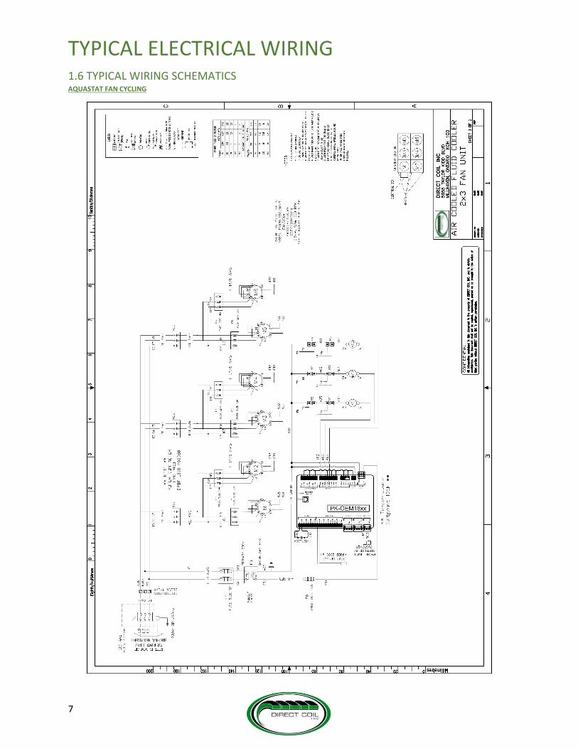
1.6 TYPICAL WIRING SCHEMATICS AQUASTAT FAN CYCLING

TYPICAL ELECTRICAL WIRING
8
HYBRID FIRST FANS EC, REST OF FANS AC

TYPICAL ELECTRICAL WIRING
9
HYBRID FIRST 2 FANS 2 SPEED, REST OF FANS SINGLE SPEED
TYPICAL ELECTRICAL WIRING
10
WIRING DIAGRAM INSPECTION
Check and ensure that the wiring diagram supplied with the fluid cooler is correctly installed and completed:
For reference, use the data provided on the unit name plate, which has information on each model.
MAIN ELECTRICAL CONNECTION
According to local electrical codes and safety standards, it is required that only a licensed electrician connects your unit to the main power
supply.
If for local codes or other reasons, the cable size of the power supply line is greater than the terminal size on the main disconnect or power
block:
I. Fit a junction box to the unit to reduce the cable size, while in compliance with local codes, or
II. Get approval from the manufacturer to replace the main disconnect switch or power block of the unit.

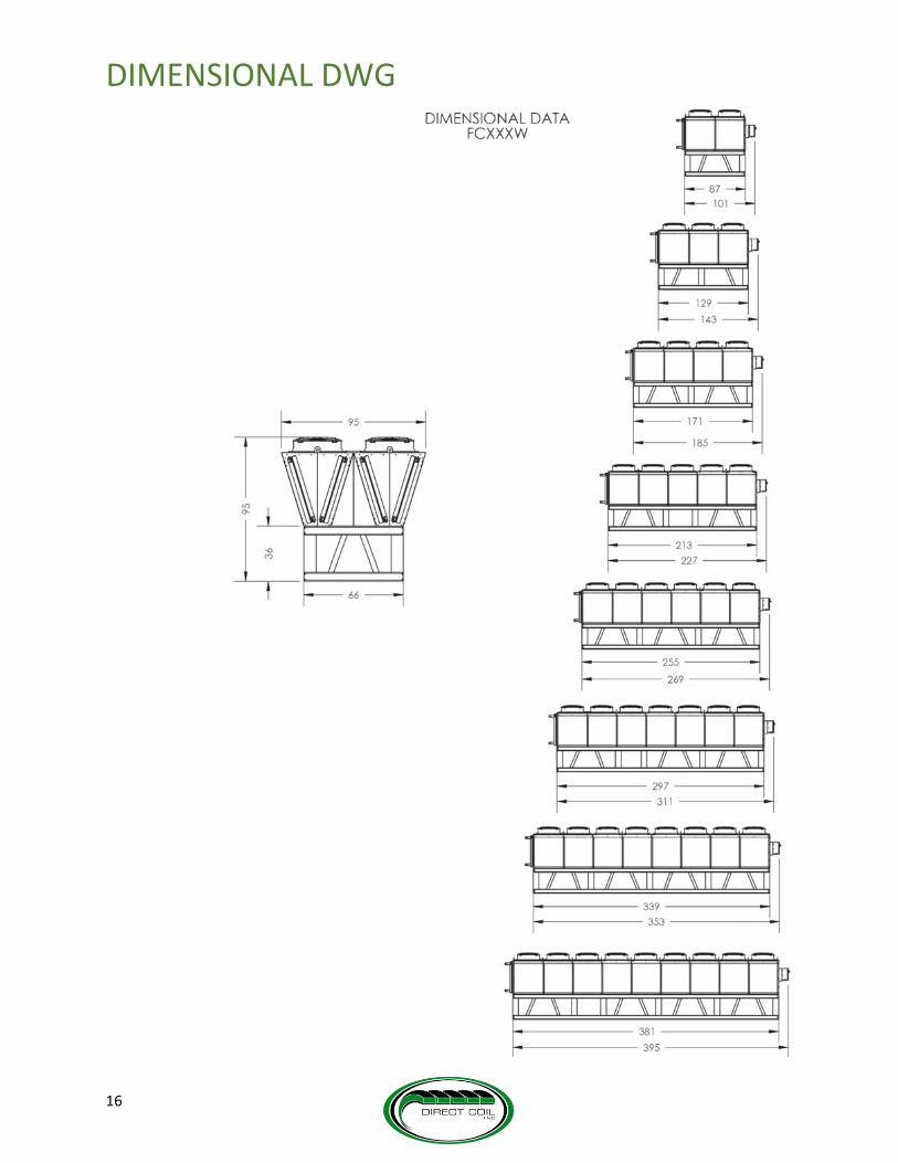
DIMENSIONAL DWG
11
1.7 DIMENSIONAL DRAWINGS

DIMENSIONAL DWG
12

DIMENSIONAL DWG
13

DIMENSIONAL DWG
14

DIMENSIONAL DWG
15
DIMENSIONAL DWG
16

17
2.0 INSTALLATION
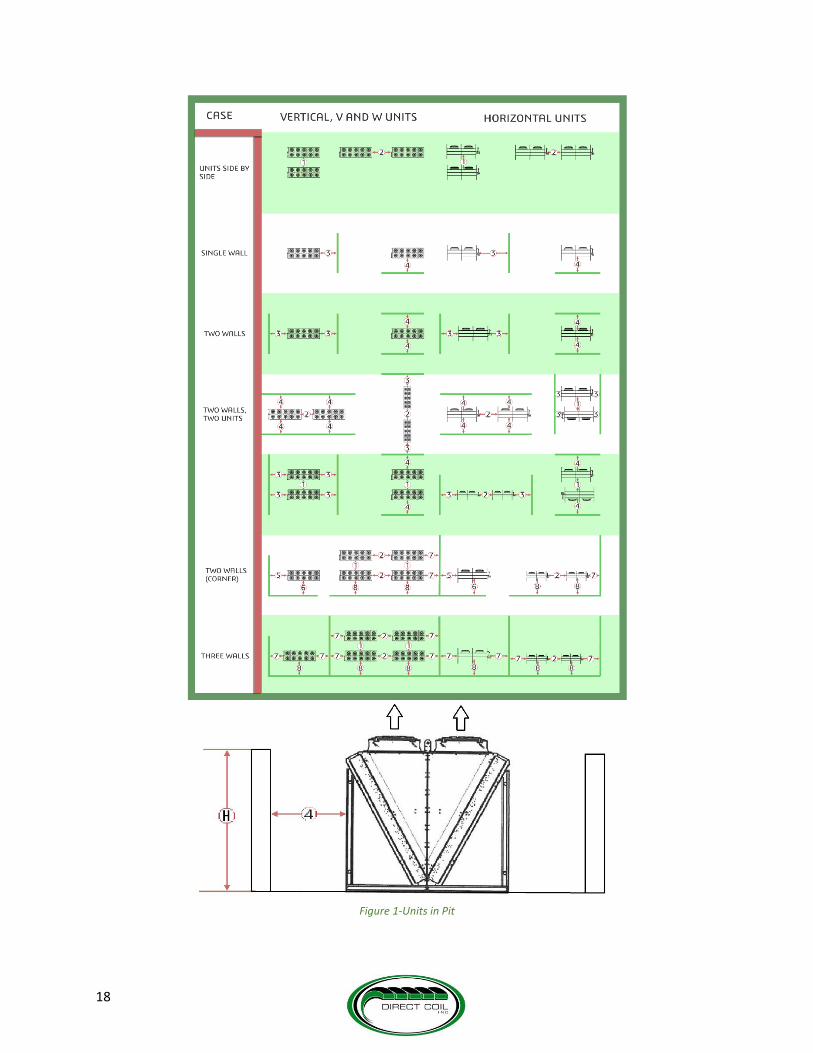
2.1 SITE SELECTION For optimum performance of your unit, consider the following factors when selecting a location for its operation;
1. Availability of ambient air to the fluid cooler unit, and space for removal of heated air - If space is not given for airflow, the unit
will operate poorly leading to a reduced lifespan if it continues to run in those conditions for a long period of time.
2. Distance to suitable electrical and fluid supply – If the unit is placed too far from an electrical and fluid supply, extra costs may
apply as wiring and piping will need to be extended. Extra pumps may also be necessary in order to achieve the desired flow rate.
3. Distance from noise sensitive spaces - Vibrations and noise from the motors and fans should be considered.
4. Loading capacity of the roof or floor –Fluid coolers can get to large sizes and weights that will require a proper support structure to
stand on. If the structure’s loading capacity is relatively low, it may lead to concaving and eventual failure.
5. Building codes.
All sides of the unit must be a minimum of 4 feet away from any walls or obstacles. It is crucial not to place units under a covered area, to allow
the dispersal of the exhaust air.
The height of the walls around the unit should not exceed the height of the unit, as the walls can block the exhaust air from leaving, leading to
recirculation and poor performance of your unit. Table 2 - Distance from wall demonstrates the best orientations and dimensions for
the best performance of your unit(s) in the different cases. The specific dimensions can be found in Table 1 - Distance from wall
dimensions. The special case of a unit in a pit (4 -walls) is demonstrated in Figure 1-Units in Pit. The dimension for H can be determined by
checking the height of your unit in section 1.7 DIMENSIONAL DRAWINGS, which should never be greater than the unit height.
DIMENSION VERTICAL, V AND W UNITS HORIZONTAL UNITS
96” 96”
48” 48”
48” 48”
48” 48”
48” 48”
48” 48”
48” 48”
96” 96”
Table 1 - Distance from wall dimensions
1
2
3
4
5
6
7
8
18
Figure 1-Units in Pit
19
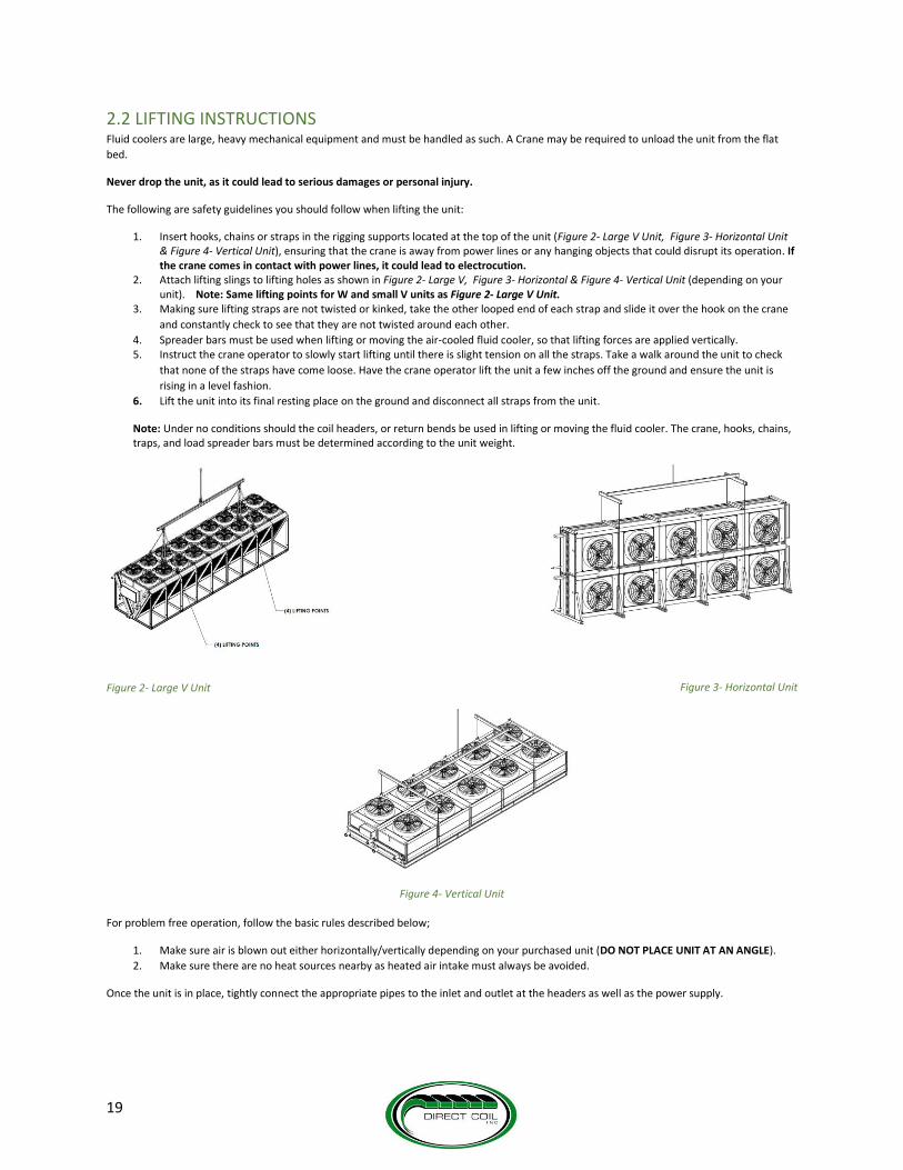
2.2 LIFTING INSTRUCTIONS Fluid coolers are large, heavy mechanical equipment and must be handled as such. A Crane may be required to unload the unit from the flat
bed.
Never drop the unit, as it could lead to serious damages or personal injury.
The following are safety guidelines you should follow when lifting the unit:
1. Insert hooks, chains or straps in the rigging supports located at the top of the unit (Figure 2- Large V Unit, Figure 3- Horizontal Unit & Figure 4- Vertical Unit), ensuring that the crane is away from power lines or any hanging objects that could disrupt its operation. If the crane comes in contact with power lines, it could lead to electrocution.
2. Attach lifting slings to lifting holes as shown in Figure 2- Large V, Figure 3- Horizontal & Figure 4- Vertical Unit (depending on your unit). Note: Same lifting points for W and small V units as Figure 2- Large V Unit.
3. Making sure lifting straps are not twisted or kinked, take the other looped end of each strap and slide it over the hook on the crane
and constantly check to see that they are not twisted around each other.
4. Spreader bars must be used when lifting or moving the air-cooled fluid cooler, so that lifting forces are applied vertically. 5. Instruct the crane operator to slowly start lifting until there is slight tension on all the straps. Take a walk around the unit to check
that none of the straps have come loose. Have the crane operator lift the unit a few inches off the ground and ensure the unit is
rising in a level fashion.
6. Lift the unit into its final resting place on the ground and disconnect all straps from the unit.
Note: Under no conditions should the coil headers, or return bends be used in lifting or moving the fluid cooler. The crane, hooks, chains, traps, and load spreader bars must be determined according to the unit weight.
Figure 3- Horizontal Unit
Figure 4- Vertical Unit
For problem free operation, follow the basic rules described below;
1. Make sure air is blown out either horizontally/vertically depending on your purchased unit (DO NOT PLACE UNIT AT AN ANGLE).
2. Make sure there are no heat sources nearby as heated air intake must always be avoided.
Once the unit is in place, tightly connect the appropriate pipes to the inlet and outlet at the headers as well as the power supply.
Figure 2- Large V Unit
20
2.4 START UP Note: Start up must be performed by authorized personnel only.
After installation, ensure the unit is ready to operate by going through the checklist for completed installation, prior to start up. Fill in the table
in page 27 and send a copy to Direct Coil for confirmation.
Follow the steps below to ensure a problem free start-up for your unit:
I. Check for correct fan rotation, which can be done by quickly jogging the fan contactor and making sure the fans run freely.
II. Check the electrical characteristics of all components to be sure they agree with the power supply.
III. Check tightness of all electrical connections.
IV. Pressure test the system before adding the water/glycol solution. Test pressure should not exceed 60 PSI
V. Pour premixed water and glycol into expansion tank. Fill the system until the expansion tank is half full, then purge air from all vents.
Operate system for a minute then purge all vents again and add glycol as required. Repeat the purging of all vents after the first hour
of operation and again after several hours of operation.
VI. For roof mounted units, to fill the system, a premixed water and glycol mixture is needed, and is to be poured into the expansion
tank. Fill the system until half full, then eliminate the air from all vents.
VII. Once the system is completely full of fluid, start the fluid circulating pump. To assure proper fluid flow, adjust the shut off valve for
the required GPM by checking the pump curve and observing gauge pressure, or by using an in-line flow meter.
VIII. Keep all wiring diagrams, instructions, list of spare parts, within easy reach of the installed fluid cooler, for future references.
2.5 PIPING SCHEMATICS After both glycol lines are connected, the entire system must be leak tested. Care should be given to those parts which will be inaccessible in
future dates. This section is a guide for the correct installation of the cooled water piping system, enclosing this fluid cooler. However, Direct
Coil accepts no responsibility whatsoever for the installation of the unit or the associated piping.
All piping must be installed only by a licensed plumbing contractor, and in compliance with local codes.
DO NOT USE GALVANIZED PIPNG IF GLYCOL IS TO BE USED IN THE CHILLED WATER SYSTEM.
Chemical reaction between the glycol and the galvanized piping can be detrimental to the cooling system, the glycol and unit. Piping material
may be copper, plastic, carbon or stainless steel depending on the requirements of each installation.
It is the responsibility of the engineer and/or the piping contractor to ensure that the piping is correctly sized in relation to the installation, and
the available dynamic head of the pump installed inside the chiller. The chilled water pipe connections on the chiller are not necessarily the
appropriate size for the system piping. As a general guide, the chiller pipe connections should be considered as minimum pipe size required for
the installation. Drastic reduction in pipe sizing (small hoses, etc.) will reduce the chilled water flow and may cause a low flow alarm, or freezing
damage to the evaporator. Note: Installation with low water flow/high water temperature rise should always have a full ported bypass installed
between the chiller inlet and outlet connections, with a manually adjustable gate valve in the bypass line. Correctly adjusted, this blended
return water will maintain an adequate flow through the chiller, at an acceptable return temperature.
ALWAYS install a filter/strainer on the inlet of the chiller in order to prevent particulates (rust, dirt and installation debris) from blocking the
evaporator. Blockage will severely impair chiller performance and is not covered by warranty.
Always install a pressure gauge in the return piping to the chiller. This is essential for monitoring system pressure and pump performance.
It is good piping practice, especially on systems with short piping runs and/or low system pressure loss, to install a gate valve in the discharge
line from the chiller for throttling purposes. This allows the operator to maintain optimum pump performance by adding resistance to the
system. NEVER throttle the water flow on the return line to the unit. This will cause cavitation and over-heating of the pump. The figure below
(Figure 5- Typical Piping Schematics) illustrates a typical configuration when installing pipes.

21
Figure 5- Typical Piping Schematics
3.0 MAINTENANCE Inspection must always be carried out by a qualified service mechanic it is recommended that it takes place semiannually. Always have the
main power supply disconnected when carrying out inspection.
During inspection, be sure to;
1. Check electrical components and tighten any loose connections.
2. Check control capillary tubes and lines for signs of wear due to excessive vibration or rubbing on metal. Secure if necessary.
3. Check tightness of all fans and motor mounts. Remove any deposits which could affect fan balance. Note: Fan motors are
permanently lubricated and require only visual inspection.
4. Clean the condenser coil using compressed air or by flushing with cool water or coil cleansers
3.1 HEAT EXCHANGER CLEANING Make sure to regularly clean up your heat exchanger to prevent building up of dust, which will affect the performance of your unit if left
unattended.
Before cleaning up the unit, make sure to shut off the unit and power off the fans to eliminate the risk of getting shocked.
Clean the Heat exchanger with one of the following procedures:
1. Hydraulic
2. Compressed air
Note: The fins can be damaged by using too high pressure or if the jet hits the fins at an angle. Mechanical cleaning using steel brushes could
damage the heat exchanger. Ensure that electrical connections and motors are not touched by water.

22
Hydraulic Cleaning
Use a maximum pressure of 500 PSI. Use warm water 80 F.
Maintain a minimum distance of 8’’ from the fins. Always aim the jet vertically.
Cleaning should ideally be done against the airflow direction, from top to bottom.
Hold the jet vertical to the fins to avoid bending the fins.
With oily and greasy dirt, it helps to add a cleaning agent to the water.
Ensure that the cleaning agent is environment friendly and compatible with the unit material.
When using chemical agents ensure that they are not aggressive towards the unit materials. Rinse the unit after the treatment.
The unit should be completely dry before switching the fans on.
Figure 6 - Pressure Cleaning
Cleaning with compressed air
Blast the heat exchanger with a maximum 1000 PSI pressure compressed air against the airflow to remove the dirt and contaminants.
Hold the jet of the cleaner vertical to the fins to avoid bending the fins.
23
3.2 TROUBLESHOOTING & RECOMMENDATIONS Possible malfunctions to the fluid cooler may occur due to:
1. Changes in operating conditions
2. Insufficient maintenance and inspection
3. External environmental factors
4. Internal machine factors
5. System factors
6. Operating errors
Causes of Malfunctions can be divided into three groups and these are:
i. Faults due to the water circuit
ii. Electrical faults
iii. Faults in the refrigerant circuit
The table below lists a large portion of problems that might occur in practice and gives descriptions intended for information only. The
information in the table must not be considered as a repair manual. Often the cause of failure is due to multiple factors and therefore can
only be evaluated by a qualified refrigeration company with precise knowledge of the functional interactions.

TROUBLESHOOTING AND RECOMMENDATIONS
24
SYMPTOM PROBABLE CAUSE RECOMMENDTION
Unit Fails to Start Incorrect phasing or voltage
Correct phase or voltage input
Power failure
Check power source, power input and fuses. Check control wiring and connections.
Overload protection tripped Check for cause of overload and repair
Fuse blown Change fuse – Identify the fault
Control is Erratic Wiring improperly connected or broken. Check wiring against schematic diagram.
Pressure Too High Low dry cooler airflow. (Indicated by excessive warm air leaving the dry cooler fan).
Open air passages. Clean coil. Check dry cooler fan(s).
Dry cooler fan(s) not operating i. Check main voltage power source to unit.
ii. Check fan motor, contactor and fan cycling switch.
iii. Check temperature switches and motor. Replace as needed.
Condenser pressure regulating valve setting too high.
Adjust to obtain correct pressure.
Air in the system Purge air with additional water/glycol solution.
Erratic Fan Operation Dirty or blocked dry cooler coil. Clean coil or remove blockage.
Pump will not prime or retain prime after operation
Air leak in suction line Repair or replace suction Line
Low glycol charge Add glycol
Flow rate is low Piping is fouled or damaged Clean or replace damaged piping.
Clogged impeller or worn impeller. Clean or replace impeller.
Discharge line restricted or undersized. Remove restrictions.
Plumbing restrictions. Remove restrictions.
Low glycol charge. Add glycol.
Air in system Purge
Low voltage Consult Direct Coil.
Pump runs but no fluid is pumped Faulty suction piping Replace piping
Valves closed Open valves
Refrigeration valves closed Start refrigeration system adjust valves
Liquid drips from point where shaft enters the pump is full of liquid.
Damaged mechanical seal Replace mechanical
Temperatures over 210 F, liquid is not compatible with seal
Replace seal
Excessive noise while pump in operation Pump not secured to firm foundation Secure pump properly
Piping not supported to relieve any strain on pump assembly.
Make necessary adjustments
Restricted suction line Clean or correct strainer
Low glycol charge Add glycol
By-pass valve requires adjustment Check
Main voltage too low Main power grid low Contact electric company
Damaged contacts or burnt coil Defective starter contactor Repair or replace
Poor system performance System not balanced Balance system
Bypass not installed Install system in accordance with recommended piping diagrams
Worn impeller or seals Replace impeller or seals as necessary
Worn motor bearings Replace pump
Table 3 - Troubleshooting and Recommendations

25
4.0 ADIABATIC COOLING SYSTEM
Figure 7 - Adiabatic Cooling System Assembly
The adiabatic cooling system uses the concept of evaporation to cool down air going through the mesh, leading to an improved performance of
your fluid cooler unit. The system is equipped with a water spray which is triggered by an intelligent controller, that calculates optimal time
intervals and spray duration, which helps in keeping water consumption at a minimum. The spray has low pressure nozzles that can operate
with mains water pressure (29 PSI). The cooling system works best in warm, dry conditions and the efficiency is usually higher in locations
where the condensing temperatures are low. As the efficiency increases (average of 20-30% higher output), the consumption of electricity
decreases as well as the running costs (an average of 15-25% in annual cost savings).
The system has three major components:
I. A non-metallic mesh fitted across the air path to the air-cooled condenser.
II. A water supply system, which intermittently sprays water onto the mesh to ensure that it is always saturated.
a. If the water pressure is low, a pumping system may be required. If not, water direct from the mains can be used. Note:
For spray system to operate efficiently, the mains pressure must be around 29 PSI or above
III. A controller to ensure the water is controlled and only used when required to cool the air.
4.1 INSTALLATION In most cases, Direct Coil takes care of the mesh installation during the manufacturing of your unit, but if you wish to install the system at a
later date, or wish to have a different qualified contractor to install it for you, the guidelines in this section show how the system is installed.
More information on the product can be found on the company website.
If the installation of the adiabatic cooling system has been performed by Direct Coil, only the water supply would need to be connected to the
headers of the system once your unit is fully installed on site. If the water is supplied by the city mains water without any tank, reservoir or
pump, there will be no requirement to report the installation to local authorities. If other water sources are used, a filter may be necessary in
order to protect the spray nozzles. This is due to water hardness, which is a result of naturally occurring calcium and magnesium salts. Water
containing small amounts of these salts is said to be soft whilst hard water contains greater levels.
Temporary hardness is usually the result of dissolved calcium carbonate typically seen as the whitish colored scale seen in kettles. Permanent
hardness contains sulphates of calcium and magnesium which remain soluble in most ambient temperatures. It is therefore vital to observe
that the coil remains dry when the nozzles are spraying to prevent scale build up, which would require mechanical removal. If the water is
evaporated on the mesh only, no water requirement will be necessary, but may cause scaling on the mesh, so it is important to make sure that
the airflow is not blocked. Treatment is only required if the water is very hard and may be required if it is hard.
4.2 MAINTENANCE The adiabatic cooling system requires minimal maintenance since it has no moving parts and has self-cleaning filter features, however, regular
quarterly and annual visits are recommended in order to check on the condition of the mesh. The three main groups; the mesh panels, the
water header and control circuit, all need to be considered when performing maintenance. If you wish to keep a record of your maintenance
checks, scan the table below and fill in the checkboxes if applicable. Record the date of the maintenance check at the bottom of the table and
keep in file.

ADIABADIC COOLING SYSTEM
26
MESH PANELS
DESCRIPTION QUARTERLY ANNUAL
CHECK FOR RECCOMMENDATION CHECK FOR RECCOMMENDATION
Mesh Panels a) Edges b) Fine Mesh c) Coarse Mesh
Visual damage Repair/ Replace Damaged Panels
Visual damage Repair/ Replace Damaged Panels
CONTROL CIRCUIT
DESCRIPTION QUARTERLY ANNUAL
CHECK FOR RECCOMMENDATION CHECK FOR RECCOMMENDATION
Controller a) Power Circuit b) Terminals c) Probe d) Functions e) Settings
Visual damage Malfunction
Repair, Replace Reboot system
Visual damage Spray interval and control settings Correct ambient temperature reading at probe unit
Repair, Replace
Temperature Probe a) Terminal b) Connection c) Location
Visual damage Malfunction
Repair, Replace
Visual damage Faulty connection and test against an external temperature reading
Repair, Replace
Solenoid Valve a) Terminal b) Connection c) Function
Visual damage
Repair, Replace
Check any visual damage, test via temperature controller override function and cable connections
Repair, Replace
Power Supply a) Fuses b) Connections c) Circuit d) Earth e) Leakage
Visual damage Loose connections
Repair, Replace
Check any visual damage and test the circuit for any earth leakage and check the overall power supply condition and repair where necessary Visual damage
Repair, Replace
WATER HEADER
DESCRIPTION QUARTERLY ANNUAL
CHECK FOR RECCOMMENDATION CHECK FOR RECCOMMENDATION
Header a) Water Intake b) Main Header c) Nozzle Sets d) Connections e) End Stop
Visual damage Leakage
Repair where necessary
Visual damage Water leakage Quality of water flow Free nozzle spray
Repair, Replace
Leakage a) Pipe Connections b) Fittings c) Nozzles d) Solenoid Valve
Visual damage Malfunction
Repair, Replace
Visual damage Water flow condition
Ensure full nozzle flow
Spray Pattern a) Angle b) Distance c) Flow Pattern d) Coverage
Visual damage Malfunction
Repair, Replace Re-adjust angle of the nozzles Adjust the water pressure
Visual damage Faulty connection on header and nozzle fittings
Repair, Replace
Nozzles a) Nozzle tip b) Body/Holder c) Check valve d) Pipe Clip e) Rings/ Seals
Visual damage Nozzle tips Valve and pipe connections
Repair, Replace where necessary
Unequal nozzle flow
Repair, Replace Override the controller and ensure equal flow and spray pattern from all the nozzles.
Date performed: __________________ Date performed: ____________________

27
START UP CHECKLIST Fill in the following information for your Direct Coil Unit package. Forward a copy of this registration sheet to [email protected] to register
your warranty.
GENERAL INFORMATION
Job Number: ___________________ Contractor Name: ___________________
Pump Package Serial Number: ___________________ Project Name: ___________________
Pump Package Model: ___________________ Direct Coil Rep: ___________________
Fluidcooler Serial Number: ___________________ Test Technician’s Initials: ___________________
Fluidcooler Model: ___________________ Date: ____/____/____
OPERATING INFORMATION ELECTRICAL COMPONENTS
Return Glycol Temp: _________________ºF DB Flow Switch: Pass N/A
Supply Glycol Temp: _________________ºF DB Pump-1 Overload: Pass N/A
System Flow Rate: _________________GPM Pump-2 Overload: Pass N/A
Total System Head: _________________Ft H2O Pump-3 Overload: Pass N/A
Glycol Solution: Ethylene Propylene Pump Enable: Pass N/A
Glycol Solution: ___________________% Fluidcooler Enable: Pass N/A
Static Pressure Setting: ___________________psig Alarm Contacts: Pass N/A
ELECTRICAL MEASUREMENTS
Main Power (Design): ___V/___Ph___Hz
Main Power (Measured): ___V
Control Voltage (Measured): ___V
Line #1 Line #2 Line #3 Rated
(Amps) (Amps) (Amps) (Amps)
Pump-1: ______ ______ ______ ______
Pump-2: ______ ______ ______ ______
Pump-3: ______ ______ ______ ______
FluidCooler Fan-1: ______ ______ ______ ______
FluidCooler Fan-2: ______ ______ ______ ______
FluidCooler Fan-3: ______ ______ ______ ______
FluidCooler Fan-4: ______ ______ ______ ______
FluidCooler Fan-5: ______ ______ ______ ______
FluidCooler Fan-6: ______ ______ ______ ______
FluidCooler Fan-7: ______ ______ ______ ______
FluidCooler Fan-8: ______ ______ ______ ______
FluidCooler Fan-9: ______ ______ ______ ______
FluidCooler Fan-10: ______ ______ ______ ______
FluidCooler Fan-11: ______ ______ ______ ______
FluidCooler Fan-12: ______ ______ ______ ______
FluidCooler Fan-13: ______ ______ ______ ______
FluidCooler Fan-14: ______ ______ ______ ______ FluidCooler Fan-15: ______ ______ ______ ______ FluidCooler Fan-16: ______ ______ ______ ______ FluidCooler Fan-17: ______ ______ ______ ______ FluidCooler Fan-18: ______ ______ ______ ______
Notes:

28
PRODUCT SUPPORT Direct Coil is committed to supporting its product installations, so if any problems occur during the installation of your unit, Direct Coil is happy
to assist in resolving the matter. You can contact us at any time between 8:30 a.m. – 5:00 p.m. Monday through Friday on our office number;
Phone : +1 (613) 544-2200 email: [email protected]
Fax : +1 (613) 544-7779
For prompt and accurate support, please prepare the following information when you contact us:
Name: ________________ Company: ________________ Phone #: _____________
Serial Number (XXMM-XXXXX-##-##) : ________________________________
Part Number (FC-XXXX) : ________________
If you are unable to catch us during business hours, please leave a message and we will get back to you as soon as possible.
Maintenance and Service Checklist
Date: ____________ Monthly
Area around fluid cooler unit is clean and clear of obstructions.
Date: ____________ Semi-Annually
Check Water/Glycol Charge Level Ensure Motor Mounts are Secured
Check % Water/Glycol Fluid Solution Clean Unit if Necessary
Ensure piping is secured Check Coil(s) and clean if necessary
Tighten Electrical Connections
Annually
Inspect Piping System for Leaks and Corrosion
Conduct a complete check of all services listed above and clean unit’s interior
Notes:
Signature:

WARRANTY
29
PRODUCT WARRANTY Direct Coil Inc. warrants to its direct purchasers that Products, including Service Parts, manufactured by the Direct Coil Inc. shall be free of defects in material or workmanship, under normal use and service for a period of one (1) year from date of original installation , or eighteen (18) months from date of shipment by Direct Coil, whichever first occurs. This warranty is not applicable if the purchaser has not fulfilled their payment obligations as per terms and conditions of sale. Any Products covered by this warranty found to Direct Coil’s satisfaction to be defective upon examination at Direct Coil’s factory will at Direct Coil’s option, be repaired or replaced and returned to Buyer via lowest common carrier, or Direct Coil may at its option grant Buyer a credit for the purchase price of the defective Product. Buyer must pay all costs for transportation of Products to Direct Coil’s factory. The repair or replacement of such defects shall constitute full performance by Direct Coil of its obligations under this warranty. Product loss of any type is not covered. Refrigerant loss is not covered. Direct Coil Inc. shall have no liability for expenses incurred for repairs made by Buyer except by prior, written authorization. Any claim under this warranty shall be made to Direct Coil in writing within the warranty period specified above otherwise such claim shall be deemed waived. In the event that parts of equipment have to be returned to the factory for repairs, return goods authorization number must be obtained by contacting sales department. No return goods shipment will be accepted without an authorization number. Direct Coil Inc. shall have no warranty obligation whatsoever if its products have been subjected to alteration, misuse, negligence, free chemicals in system, corrosive atmosphere, accident, or if operation is contrary to Direct Coil’s or manufacturer’s recommendations, or if the serial number has been altered, defaced, or moved. Direct Coil Inc. makes no warranty, express or implied, of fitness for any particular purpose, or of any other nature, with respect to products manufactured or sold by Direct Coil, except as specifically set forth above. No one is authorized to change this warranty or to create for on behalf of the Company any other obligation or liability in connection with the Products. It is expressly understood and agreed that Direct Coil Inc. shall not be liable to buyer, or any customer of buyer, for direct or indirect, special, incidental, consequential or penal damages, or for any expenses incurred by reason of the use or misuse by buyer or third parties of the products. All written correspondence is to be made to:
Direct Coil Inc. P.O. Box 430, Millhaven, Ontario, K0H 1G0
+1 (613) 544-2200 (Phone) +1 (613) 544-7779 (Fax)

30

31
S

WARRANTY
32