to · A 4, 1994 Collins 2011/O127044 A1 6, 2011 Radford et al. 5,318, 131 A 6, 1994 Baker...
28
US00934.1027B2 (12) United States Patent (10) Patent No.: US 9,341,027 B2 Radford et al. (45) Date of Patent: May 17, 2016 (54) EXPANDABLE REAMER ASSEMBLIES, (56) References Cited BOTTOM-HOLE ASSEMBLIES, AND RELATED METHODS U.S. PATENT DOCUMENTS (71) Applicant: Baker Hughes Incorporated, Houston, 1,678,075 A 7/1928 Phipps TX (US) 2,069,482 A 2/1937 Seay (Continued) (72) Inventors: Steven R. Radford, The Woodlands, TX (US); Marcus Oesterberg, Kingwood, FOREIGN PATENT DOCUMENTS TX (US); Khoi Q. Trinh, Pearland, TX (US); Timothy Miller, Spring, TX (US); AU 2973397 A 1, 1998 Shyam Anandampillai, Houston, TX AU T10317 B2 9, 1999 (US); Chad T. Jurica, Conroe, TX (US); (Continued) Wolfgang Eduard Herberg, Niedersachson (DE); Carsten Haubold, OTHER PUBLICATIONS Celle (DE); Christopher Jakubeit, Celle (DE); Michael Wiegmann, Gross International Search Report for International Application No. PCT/ Oesingen (DE); Jens Behnsen, Burgdorf US2014/020270 dated Jun. 26, 2014, 4 pages. (DE); Hans-Juergen Faber, Neustadt (Continued) (DE) (73) Assignee: Baker Hughes Incorporated, Houston, Primary Examiner — Jennifer H Gay TX (US) (74) Attorney, Agent, or Firm — TraskBritt (*) Notice: Subject to any disclaimer, the term of this patent is extended or adjusted under 35 (57) ABSTRACT U.S.C. 154(b) bV 482 davs. (b) by ayS Expandable reamerassemblies include an expandable reamer (21) Appl. No.: 13/784,284 module and al activation module. An outer tubular body of the activation module is rigidly coupled to a tubular body of (22) Filed: Mar. 4, 2013 the expandable reamer module, and an activation member of the activation module is coupled to a sleeve of the expandable (65) Prior Publication Data reamer module, the sleeve is coupled to at least one blade and configured to move the at least one blade into an extended US 2014/0246236A1 Sep. 4, 2014 position. The sleeve moves axially responsive to axial move ment of the activation member. Bottom-hole assemblies (51) E; 0/32 (2006.01) include an expandable reamer module and an activation mod E2IBIO/26 (200 6. 01) ule. The activation module is coupled to the expandable E2IB 47/12 (201201) reamer module and configured to provide a motive force to 52) U.S. C the sleeve to move the sleeve opposite a direction of flow of (52) CPC E2IBIO/322 (2013.O1): E2IB 47/12 drilling fluid. Methods of using expandable reamer modules - - - - - - - - - - - - - - - 2013.O1 (E21 B I 3.26 (2013.O1 include pairing two Substantially identical expandable reamer (58) Field of Classifi d S s ( .01) modules and two respective different activation modules. OSSO Sea CPC ...... E21B 47/12: E21B 10/322: E21B 17/042 See application file for complete search history. 20 Claims, 11 Drawing Sheets to
Transcript of to · A 4, 1994 Collins 2011/O127044 A1 6, 2011 Radford et al. 5,318, 131 A 6, 1994 Baker...

US00934.1027B2
(12) United States Patent (10) Patent No.: US 9,341,027 B2 Radford et al. (45) Date of Patent: May 17, 2016
(54) EXPANDABLE REAMER ASSEMBLIES, (56) References Cited BOTTOM-HOLE ASSEMBLIES, AND RELATED METHODS U.S. PATENT DOCUMENTS
(71) Applicant: Baker Hughes Incorporated, Houston, 1,678,075 A 7/1928 Phipps TX (US) 2,069,482 A 2/1937 Seay
(Continued) (72) Inventors: Steven R. Radford, The Woodlands, TX
(US); Marcus Oesterberg, Kingwood, FOREIGN PATENT DOCUMENTS TX (US); Khoi Q. Trinh, Pearland, TX (US); Timothy Miller, Spring, TX (US); AU 2973397 A 1, 1998 Shyam Anandampillai, Houston, TX AU T10317 B2 9, 1999 (US); Chad T. Jurica, Conroe, TX (US); (Continued) Wolfgang Eduard Herberg, Niedersachson (DE); Carsten Haubold, OTHER PUBLICATIONS Celle (DE); Christopher Jakubeit, Celle (DE); Michael Wiegmann, Gross International Search Report for International Application No. PCT/ Oesingen (DE); Jens Behnsen, Burgdorf US2014/020270 dated Jun. 26, 2014, 4 pages. (DE); Hans-Juergen Faber, Neustadt (Continued) (DE)
(73) Assignee: Baker Hughes Incorporated, Houston, Primary Examiner — Jennifer H Gay TX (US) (74) Attorney, Agent, or Firm — TraskBritt
(*) Notice: Subject to any disclaimer, the term of this patent is extended or adjusted under 35 (57) ABSTRACT U.S.C. 154(b) bV 482 davs.
(b) by ayS Expandable reamerassemblies include an expandable reamer (21) Appl. No.: 13/784,284 module and al activation module. An outer tubular body of
the activation module is rigidly coupled to a tubular body of (22) Filed: Mar. 4, 2013 the expandable reamer module, and an activation member of
the activation module is coupled to a sleeve of the expandable (65) Prior Publication Data reamer module, the sleeve is coupled to at least one blade and
configured to move the at least one blade into an extended US 2014/0246236A1 Sep. 4, 2014 position. The sleeve moves axially responsive to axial move
ment of the activation member. Bottom-hole assemblies (51) E; 0/32 (2006.01) include an expandable reamer module and an activation mod
E2IBIO/26 (200 6. 01) ule. The activation module is coupled to the expandable E2IB 47/12 (201201) reamer module and configured to provide a motive force to
52) U.S. C the sleeve to move the sleeve opposite a direction of flow of (52) CPC E2IBIO/322 (2013.O1): E2IB 47/12 drilling fluid. Methods of using expandable reamer modules
- - - - - - - - - - - - - - - 2013.O1 (E21 B I 3.26 (2013.O1 include pairing two Substantially identical expandable reamer
(58) Field of Classifi d S s ( .01) modules and two respective different activation modules. OSSO Sea
CPC ...... E21B 47/12: E21B 10/322: E21B 17/042 See application file for complete search history. 20 Claims, 11 Drawing Sheets
to

US 9,341,027 B2 Page 2
(56) References Cited 6,378.632 B1 4/2002 Dewey et al. 6,488,104 B1 12/2002 Eppink et al.
U.S. PATENT DOCUMENTS 6.494.272 B1 12/2002 Eppink et al. 6,615,933 B1 9, 2003 Eddison
2,177,721 A 10, 1939 Johnson et al. 6,668,936 B2 12/2003 Williamson, Jr. et al. 2,344,598. A 3/1944 Church 6,668,949 B1 12/2003 Rives 2,754,089 A 7/1956 Kammerer, Jr. 6,708,785 B1 3/2004 Russell et al. 2,758,819 A 8/1956 Kammerer, Jr. 6,732,817 B2 5/2004 Dewey et al. 2,834,578 A 5, 1958 Carr 7,036,611 B2 5, 2006 Radford et al. 2,882,019 A 4, 1959 Carr et al. 7,048,078 B2 5/2006 Dewey et al. 3,105,562 A 10, 1963 Stone et al. 7,252,163 B2 * 8/2007 Ollerenshaw ........... E21B 7,062 3,123,162. A 3/1964 Rowle 175/269 3,126,065. A 3/1964 Gerdon 7,314,099 B2 1/2008 Dewey et al. 3,208,540 A * 9, 1965 Park .............................. 175/269 7,513,318 B2 4/2009 Underwood et al. 3,211,232 A 10, 1965 Grimmer 7,681,666 B2 3/2010 Radford et al. 3,224,507 A 12/1965 Cordary, Jr. 7,823,663 B2 * 1 1/2010 Eddison ........................ 175/269 3.425,500 A 2f1969 Fuchs 7,900,717 B2 3/2011 Radford et al. 3.433,313 A 3, 1969 Brown 8,020,635 B2 9, 2011 Radford 3,472,533 A * 10/1969 Turner ............................ 285/55 8,074,747 B2 12/2011 Radford et al. 3,556.233 A 1/1971 Gilreath et al. 8,118,101 B2 2/2012 Nelson et al. 4,055,226 A 10, 1977 Weber 8,196,679 B2 6, 2012 Radford 4,231.437 A 1 1/1980 Swersky et al. 8,230,951 B2 7/2012 Radford et al. 4,366,971 A 1, 1983 Lula ................................ 285/55 8,297,381 B2 10/2012 Radford et al. 4,403,659 A 9/1983 Upchurch 8,485.282 B2 * 7/2013 Gentry .......................... 175/271 4.458,761 A 7/1984 Van Vreeswyk 8,844,635 B2* 9/2014 Oxford ........ ... 166,376 4,545,441 A 10, 1985 Williamson 8,881.833 B2 * 1 1/2014 Radford et al. . 166.382 4,589,504 A 5/1986 Simpson 8,936,110 B2 1/2015 Adam ............................. 175/57 4,660,657 A 4, 1987 Furse et al. 2002fOO70052 A1 6/2002 Armell et al. 4,690,229 A 9/1987 Raney 2003, OO29644 A1 2/2003 Hoffmaster et al. 4,693,328 A 9, 1987 Furse et al. 2004/0222022 A1 11/2004 Nevludet al. 4,698,794. A 10/1987 Kruger et al. 2005, 01454.17 A1 7/2005 Radford et al. 4,842,083. A 6/1989 Raney 2006/0144.623 A1* 7/2006 Ollerensaw ............. E21B 7,062 4,848,490 A 7/1989 Anderson 175/269 4,854,403 A 8/1989 Ostertaget al. 2007/0O899 12 A1 4/2007 Eddison 4,856,828 A * 8/1989 Kessler et al. ............. 285,334.1 2008.0128175 A1 6/2008 Radford et al. ............... 175/269 4,884,477 A 12/1989 Smith et al. 2009/0032308 A1 2/2009 Eddison ........................ 175/267 4,889,197 A 12, 1989 Boe 2010.0089583 A1* 4/2010 Xu et al. ....................... 166,298 5,065,825 A 11, 1991 Bardin et al. 2010, 0108.394 A1* 5, 2010 Ollerenshaw ....... E21B 175,284 5,074,356 A 12/1991 Neff 175,284 5,129,689 A * 7/1992 Newski et al. ................ 285/.333 2010, O139981 A1 6, 2010 Meister et al. 5,139,098 A 8, 1992 Blake 2010.0193248 A1 8, 2010 Radford et al. 5,211,241 A 5, 1993 Mashaw et al. 2010/0224414 A1 9/2010 Radford et al. 5,224,558 A 7, 1993 Lee 2011/000583.6 A1 1/2011 Radford et al. ................. 175/57 5,265,684. A 1 1/1993 Rosenhauch 2011/0073370 A1 3/2011 Gentry 5,293,945 A 3, 1994 Rosenhauch et al. 2011/0073376 A1 3/2011 Radford et al. ............... 175/269 5,305,833. A 4, 1994 Collins 2011/O127044 A1 6, 2011 Radford et al. 5,318, 131 A 6, 1994 Baker 2011/023.2915 A1 9, 2011 Kellner et al. 5,318,137 A 6, 1994 Johnson et al. 2011/0284233 A1 11, 2011 Wu et al. 5,318,138 A 6/1994 Dewey et al. 2012fOO18173 A1 1/2012 Herberg et al. 5,332,048 A 7, 1994 Underwood et al. 2012/0048571 A1 3/2012 Radford et al. ............... 166/373 5,343,963 A 9, 1994 Bouldin et al. 2012/00557.14 A1 3/2012 Adam ............................. 175/57 5,361,859 A 11, 1994 Tibbitts 2012, 0080183 A1 4/2012 Radford et al. 5,368,114 A 11/1994 Tandberg et al. 2012/0080231 A1* 4/2012 Radford et al. ................. 175/57 5,375,662 A 12/1994 Echols, III et al. 2012fO298422 A1* 11, 2012 Oxford ........... 175/57 5,402,856 A 4/1995 Warren 2014/0246236 A1* 9, 2014 Radford et al. . 175/40 5,406,983 A * 4, 1995 Chambers et al. ............ 138,109 2014/0246246 A1* 9, 2014 Radford ........................ 175/270 5,415,243 A 5/1995 Lyon et al. 5.425,423. A 6, 1995 Dobson et al. FOREIGN PATENT DOCUMENTS 5.437,308 A 8, 1995 Morin et al. 5,553,678 A 9, 1996 Barr et al. EP 246789 A2 11, 1987 5,560,440 A 10, 1996 Tibbitts EP O301890 A2 2, 1989 5,740,864 A 4, 1998 de Hoedt et al. EP O301890 A3 2, 1989 5,765,653 A 6, 1998 Doster et al. EP O301890 B1 2, 1989 5,788,000 A 8/1998 Maury et al. EP 059.4420 A1 4f1994 5,823,254 A 10, 1998 Dobson et al. EP 059.4420 B1 4f1994 5,826,652. A 10/1998 Tapp EP 1036913 A1 9, 2000 5,887,655 A 3/1999 Haugen et al. EP 1044314 A1 10, 2000 6,039,131 A 3, 2000 Beaton GB 2328964. A 3, 1999 6,059,051 A 5, 2000 Jewkes et al. GB 2344122. A 5, 2000 6,070,677 A 6, 2000 Johnston GB 2344607 A 6, 2000 6,109,354 A 8/2000 Ringgenberg et al. GB 2344122 B 4/2003 6,116,336 A 9, 2000 Adkins et al. GB 2385344 A 8, 2003 6,131,675 A 10, 2000 Anderson WO 97.47849 A1 12/1997 6,189.631 B1 2/2001 Sheshtawy WO 9928587 A1 6, 1999 6,213,226 B1 4/2001 Eppink et al. WO 9928.588 A1 6, 1999 6,227,312 B1 5/2001 Eppink et al. WO OO31371 A1 6, 2000 6,289.999 B1 9/2001 Dewey et al. WO 200408.8091 A1 10, 2004 6,325,151 B1 12/2001 Vincent et al. WO 2009132462 A1 11 2009 6,360,831 B1 3/2002 Akesson et al. OTHER PUBLICATIONS

US 9,341,027 B2 Page 3
(56) References Cited Radford, Steven R., U.S. Appl. No. 13/784,307, titled “Actuation Assemblies, Hydraulically Actuated Tools for Use in Subterranean
OTHER PUBLICATIONS Boreholes Including Actuation Assemblies and Related Methods” filed Mar. 4, 2013.
International Written Opinion for International Application No. PCT/ US2014/020270 dated Jun. 26, 2014, 6 pages. * cited by examiner

US 9,341,027 B2 Sheet 1 of 11 May 17, 2016 U.S. Patent
US 9,341,027 B2 Sheet 2 of 11 May 17, 2016 U.S. Patent

U.S. Patent May 17, 2016 Sheet 3 of 11 US 9,341,027 B2
o 216 229 202 220 222 224 226
----- user esseek --
206 H.
- r-"LU"( teetes
2 218
32 228
FIG. 4
200 y 2O2 229 220 222 224 226
O ran fans (3 In , "
- I-77 zeezy'
230 232 228
FIG. 5

U.S. Patent May 17, 2016 Sheet 4 of 11 US 9,341,027 B2
Ltd to E \ .
2%2 234
FIG. 6
200
238 40 A
C---- Nas N 2
206 44/.444
PT-P-1
248
3 246 244
FIG. 7

US 9,341,027 B2 Sheet 5 of 11 May 17, 2016 U.S. Patent
U.S. Patent May 17, 2016 Sheet 6 of 11 US 9,341,027 B2
U.S. Patent May 17, 2016 Sheet 7 of 11 US 9,341,027 B2
300 \,

US 9,341,027 B2 Sheet 8 of 11 May 17, 2016 U.S. Patent
U.S. Patent May 17, 2016 Sheet 9 of 11 US 9,341,027 B2
400
410 402 412
404 47/7/777/7////777/7ZZ/////
O O O O of N(Z2 S N N S N N N N N N N N N S N N S N N N N \, SaaSSSSSSSSSSSSSSSYYYYY
Ya Ya NY, YS.N.S.N. Y. S.Y. NY Ya YNY YYYY SNSS N N S S A N N
olo to o O ON/72
406
FIG. 13
400
410 402 412
K-42.24/7/47 -- as a case a are \ / Nels, 9&N Cls 2 ON OOOOOO Y/ZZZ -L-E-2214
406 404
FIG. 14

U.S. Patent May 17, 2016 Sheet 10 of 11 US 9,341,027 B2
216A
504 508 516 ? 506
N 777-12sgx/VHTYRNXylar
503 512 514 510
FIG. 15
504 508 524 506
24ss
Z
ZZ
crysee 2-632WZZrt.
512 510
FIG 16
503

U.S. Patent May 17, 2016 Sheet 11 of 11 US 9,341,027 B2
o 4. 202
NkZNa S22'SN E1 DIT III 206
FIG. 17
o
R & sess issuess?? eyesizizisztery S
216 502 280
FIG. 18
202
206

US 9,341,027 B2 1.
EXPANDABLE REAMER ASSEMBLIES, BOTTOM-HOLE ASSEMBLIES, AND
RELATED METHODS
TECHNICAL FIELD
The present disclosure relates generally to expandable reamer assemblies for reaming a subterranean formation, as well as bottom-hole assemblies including expandable reamer assemblies, devices and systems for activating Such expand able reamer assemblies, and related methods.
BACKGROUND
Wellbores are formed in subterranean formations for vari ous purposes including, for example, the extraction of oil and gas from a Subterranean formation and the extraction of geo thermal heat from a subterranean formation. A wellbore may be formed in a Subterranean formation using a drill bit, Such as, for example, an earth-boring rotary drill bit. Different types of earth-boring rotary drill bits are known in the art, including, for example, fixed-cutter bits (which are often referred to in the art as "drag' bits), rolling-cutter bits (which are often referred to in the art as “rock” bits), diamond impregnated bits, and hybrid bits (which may include, for example, both fixed cutters and rolling cutters). Earth-boring rotary drill bits are rotated and advanced into a subterranean formation. As the drill bit rotates, the cutters or abrasive structures thereof cut, crush, shear, and/or abrade away the formation material to form the wellbore. A diameter of the wellbore drilled by the drill bit may be defined by the cutting structures disposed at the largest outer diameter of the drill bit.
The drill bit is coupled, either directly or indirectly, to an end of what is referred to in the art as a “drill string, which comprises a series of elongated tubular segments connected end-to-end that extends into the wellbore from the surface of the formation. Often various tools and components (often referred to in the art as “subs”), including the drill bit, may be coupled together at the distal end of the drill string at the bottom of the wellbore being drilled. This assembly of tools and components is referred to in the art as a “bottom-hole assembly” (BHA). The drill bit may be rotated within the wellbore by rotating
the drill string from the surface of the formation, or the drill bit may be rotated by coupling the drill bit to a downhole motor, which is also coupled to the drill string and disposed proximate the bottom of the wellbore. The downhole motor may comprise, for example, a hydraulic Moineau-type motor having a shaft, to which the drill bit is mounted, that may be caused to rotate by pumping fluid (e.g., drilling mud or fluid) from the surface of the formation down through the center of the drill string, through the hydraulic motor, out from nozzles in the drill bit, and back up to the surface of the formation through an annular space between the outer surface of the drill string and the exposed surface of the formation within the wellbore.
It is known in the art to use what is referred to in the art as a “reamer' (also referred to in the art as a “hole opening device' or a “hole opener”) in conjunction with a drill bit as part of a BHA when drilling a wellbore in a subterranean formation. In Such a configuration, the drill bit operates as a “pilot' bit to fauna pilot bore in the subterranean formation. As the drill bit and BHA advance into the formation, the reamer follows the drill bit through the pilot bore and enlarges the diameter of, or “reams, the pilot bore.
10
15
25
30
35
40
45
50
55
60
65
2 Conventionally in drilling oil, gas, and geothermal wells,
casing is installed and cemented to prevent the wellbore walls from caving into the subterranean borehole while providing requisite shoring for Subsequent drilling operations to achieve greater depths. To increase the depth of a previously drilled borehole, new casing is laid within and extended below the previous casing. While adding casing allows a borehole to reach greater depths, it has the disadvantage of narrowing the borehole. Narrowing the borehole restricts the diameter of any subsequent sections of the well because the drill bit and any further casing must pass through the existing casing. As reductions in the borehole diameter limit the production flow rate of oil and gas through the borehole, it is often desirable to enlarge a subterranean borehole to provide a larger borehole diameter beyond previously installed casing.
Expandable reamers may include reamer blades pivotably or hingedly affixed to a tubular body and actuated by way of a piston disposed therein as disclosed by U.S. Pat. No. 5,402, 856 to Warren. In addition, U.S. Pat. No. 6,360,831 to Akes son et al. discloses a borehole opener comprising a body equipped with at least two hole opening arms having cutting means that may be moved from a position of rest in the body to an active position by exposure to pressure of the drilling fluid flowing through the body. The blades in these reamers are initially retracted to permit the tool to run through the borehole on a drill string and, once the tool has passed beyond the end of the casing, the blades are extended so the bore diameter may be increased below the casing.
Expandable reamers include activation means for moving the reamer blades thereof between a deactivated position and an expanded, activated position. For example, prior known expandable reamers include a movable sleeve coupled to the reamer blades. As the movable sleeve moves axially within a body of the expandable reamer, the reamer blades move between the deactivated position and the activated position. The movement of the movable sleeve is accomplished by causing a pressure differential to push the movable sleeve in the desired axial direction. The pressure differential is pro vided by dropping a so-called “drop ball' into the drilling fluid. An orifice in the drilling fluid flow path smaller than the drop ball is provided in the expandable reamer, such that the drop ball cannot pass the orifice. When the drop ball reaches the orifice, pressure from the drilling fluid builds up above the drop ball, pushing the drop ball downward along with the structure in which the orifice is formed. Drilling fluid may then be directed to provide pressure against the movable sleeve, moving the movable sleeve upward and, conse quently, moving the blades into the activated position. When drilling fluid pressure is released from against the movable sleeve, a spring biases the movable sleeve to move back into the deactivated position.
BRIEF SUMMARY
In Some embodiments, the present disclosure includes expandable reamer assemblies for reaming a Subterranean borehole. The expandable reamer assemblies include an expandable reamer module and an activation module. The expandable reamer module includes a tubular body, one or more blades, and a sleeve. The tubular body has alongitudinal axis and an inner bore. At least one of the blades is coupled to the tubular body and configured to move between a retracted position and an extended position. The sleeve is disposed within the inner bore of the tubular body and coupled to the at least one blade. The sleeve is configured to axially move relative to the tubular body to move the at least one blade into the extended position. The activation module includes an

US 9,341,027 B2 3
outer tubular body and an activation member at least partially disposed within an inner bore of the outer tubular body. The outer tubular body of the activation module is rigidly coupled to the tubular body of the expandable reamer module. A longitudinal end of the activation member is coupled to the sleeve to axially move the sleeve relative to the tubular body of the expandable reamer module responsive to axial move ment of the activation member.
In Some embodiments, the present disclosure includes bot tom-hole assemblies including an expandable reamer module and an activation module. The expandable reamer module includes a first tubular body and the activation module includes a second tubular body coupled to the first tubular body of the expandable reamer module. The expandable reamer module includes at least one reamer blade movably coupled to the first tubular body, and a sleeve axially movable within the first tubular body. The sleeve is coupled to the at least one reamer blade and configured to move the at least one reamer blade into an expanded position. The activation mod ule includes an activation member coupled to the sleeve and configured to provide a motive force to the sleeve toward the activation module and opposite a direction of flow of drilling fluid through the bottom-hole assembly during use of the bottom-hole assembly. Such a motive force results in move ment of the at least one reamer blade into the expanded position.
In other embodiments, the present disclosure includes methods of using expandable reamer modules. In accordance with such methods, a first expandable reamer module includ ing a tubular body and an axially movable sleeve at least partially within the tubular body is provided. A first activation module is also provided, which includes a tubular body con figured to be coupled to the tubular body of the first expand able reamer module. The first activation module also includes an axially movable activation member configured to be coupled to the sleeve of the first expandable reamer module such that axial movement of the activation member results in axial movement of the sleeve. The first activation module is configured to be activated with a first activation means. The first expandable reamer module and the first activation mod ule are paired for use in a reaming process in which the first activation module activates the first expandable reamer mod ule to ream a Subterranean formation. A second expandable reamer module is provided that is substantially identical to the first expandable reamer module. A second activation module configured to be activated with a second, different activation means is also provided. The second expandable reamer mod ule and the second activation module are paired for use in a reaming process in which the second activation module acti Vates the second expandable reamer module to ream a Sub terranean formation.
BRIEF DESCRIPTION OF THE DRAWINGS
While the disclosure concludes with claims particularly pointing out and distinctly claiming that which is regarded as the invention, various features and advantages of the disclo sure may be ascertained from the following detailed descrip tion, when read in conjunction with the accompanying draw ings, in which:
FIG. 1 is a schematic illustrating various ways in which modules can be combined to form a bottom-hole assembly (BHA), according to an embodiment of the present disclo Sure;
FIG. 2 shows a cross-sectional side view of an expandable reamer module in a deactivated position, according to an embodiment of the present disclosure;
10
15
25
30
35
40
45
50
55
60
65
4 FIG.3 shows a cross-sectional side view of the expandable
reamer module of FIG. 2 in an activated position; FIG. 4 shows a cross-sectional side view of an upper por
tion of the expandable reamer module of FIG. 2 in a deacti vated position;
FIG. 5 shows a cross-sectional side view of the upper portion of the expandable reamer module of FIG. 2 in an activated position;
FIG. 6 shows a cross-sectional view of a lower portion of the expandable reamer module of FIG. 2 in a deactivated position;
FIG. 7 shows a cross-sectional view of the lower portion of the expandable reamer module of FIG. 2 in an activated position;
FIG. 8 shows a cross-sectional perspective view of a middle portion of the expandable reamer module of FIG. 2 in an activated position;
FIG. 9 shows a perspective view the middle portion of the expandable reamer module of FIG. 2 in an activated position;
FIG. 10 shows a cross-sectional perspective view of a tubular body of the expandable reamer module of FIG. 2;
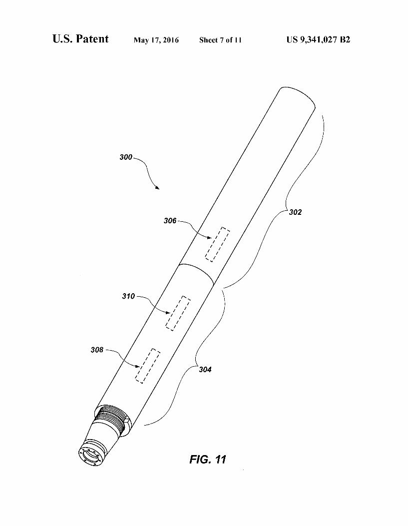
FIG. 11 shows a partially cut-away perspective view of an electronic and hydraulic component of an activation module, according to an embodiment of the present disclosure;
FIG. 12 shows a cross-sectional perspective view of a piston component of the activation module in an activated position, according to an embodiment of the present disclo Sure;
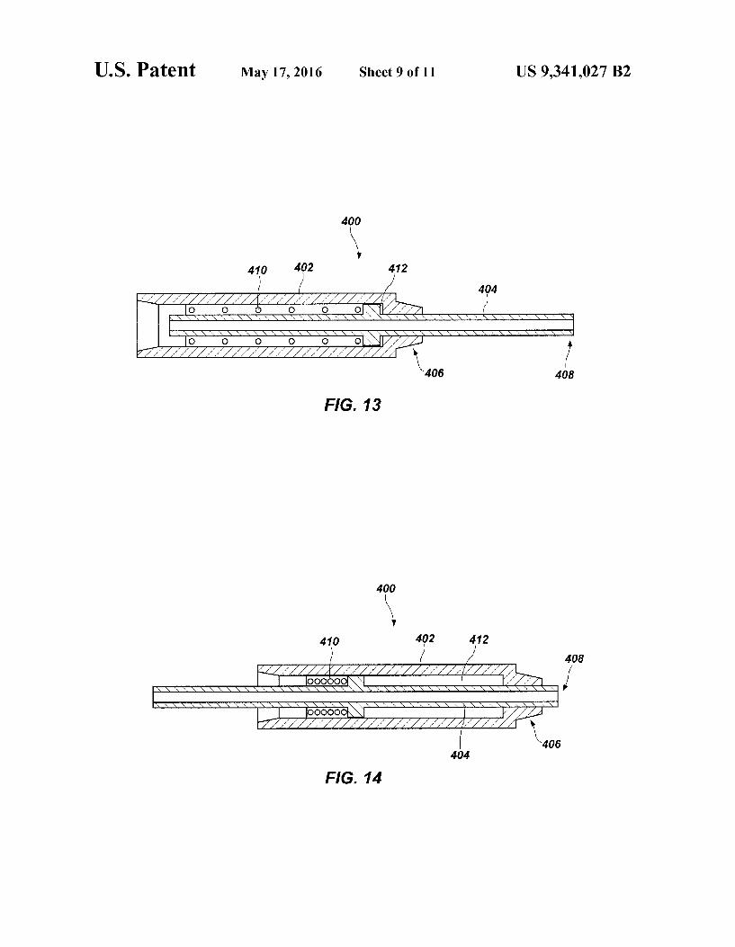
FIG. 13 shows a schematic cross-sectional view of the piston component of FIG. 12 in a deactivated position;
FIG. 14 shows a schematic cross-sectional side view of the piston component of FIG. 12 in an activated position;
FIG. 15 shows a cross-sectional side view of a joint struc ture for coupling the activation module to the expandable reamer module according to an embodiment of the present disclosure;
FIG. 16 shows a cross-sectional side view of a joint struc ture for coupling the activation module to the expandable reamer module according to another embodiment of the present disclosure;
FIG. 17 shows a cross-sectional side view of an upper portion of the expandable reamer module of FIG. 2 with the joint structure of FIG. 15 coupled to a sleeve of the expand able reamer module and a piston of the activation module; and
FIG. 18 shows an enlarged cross-sectional side view of the upper portion of the expandable reamer module similar to FIG. 17, but illustrating an addition of one or more spacers to position the joint structure of FIG. 15 at a desired location relative to the sleeve.
DETAILED DESCRIPTION
The illustrations presented herein are, in some instances, not actual views of any particular reamer tool, bottom-hole assembly (BHA), expandable reamer assembly, or feature thereof, but are merely idealized representations that are employed to describe the present disclosure. Additionally, elements common between figures may retain the same numerical designation. As used herein, any relational term, such as “first.” “sec
ond,” “over,” “upper,” “lower,” “middle,” “above,” “below.” etc., is used for clarity and convenience in understanding the disclosure and accompanying drawings, and does not connote or depend on any specific preference, orientation, or order, except where the context clearly indicates otherwise. As used herein, the “substantially in reference to a given
parameter means and includes to a degree that one skilled in

US 9,341,027 B2 5
the art would understand that the given parameter, property, or condition is met with a small degree of variance, such as within acceptable manufacturing tolerances. For example, a parameter that is substantially met may be at least about 90% met, at least about 95% met, or even at least about 99% met.
Referring to FIG. 1, a schematic 100 illustrates various ways in which modules can be combined to form a bottom hole assembly (BHA) or an expandable reamer assembly for drilling into a Subterranean formation in accordance with embodiments of the present disclosure. In general, the sche matic 100 illustrates the concept that various modules may be interchangeable to form different BHAs or expandable reamer assemblies as desired, depending on various consid erations, such as the characteristics of the formation to be drilled, cost constraints, maintenance capabilities, etc. Spe cific, practical applications of this concept are disclosed herein, as well as specific modules that are configured to be interchangeable and assemblies formed by combining Such specific modules. As shown in FIG. 1, an expandable reamer module 110
may be configured to be interchangeably coupled to one of various activation modules 120. Such as an electronic and hydraulic activation module 122 or a mechanical activation module 124. As used herein, the phrase “electronic and hydraulic activation module” means and includes a module configured to activate a closed hydraulic system (i.e., a sys tem including hydraulic fluid separated from drilling fluid) using an electrical signal. The electrical signal may be gen erated at a Surface of the Subterranean formation being reamed or may be generated by the electronic and hydraulic activation module 122 in response to a non-electrical signal. An example of an electronic and hydraulic activation module that may be used as the electronic and hydraulic activation module 122 is described in detail below with reference to FIGS. 11 through 14. The electronic and hydraulic activation module 122 may be configured to be activated by receiving a signal from the Surface of the Subterranean formation using a conductive wire, a radio-frequency identification (RFID) chip carried to the electronic and hydraulic activation module 122 by drilling fluid, a predetermined sequence of pressure pulses in the drilling fluid (also referred to as “drilling fluid force telemetry”), a predetermined (e.g., high) level of pres Sure in the drilling fluid, or a predetermined (e.g., high) drill ing fluid flow rate. Once Such a signal is received, the elec tronic and hydraulic activation module 122 may electrically activate a hydraulic portion of the electronic and hydraulic activation module 122. As used herein, the phrase "mechani cal activation module” means and includes a module config ured to be activated mechanically, without the use of an electrical signal. For example, the mechanical activation module 124 may be activated by a pressure differential caused by an obstruction in a drilling fluid flow path. The obstruction may be introduced into the drilling fluid flow path, such as by dropping a drop ball into the drilling fluid flow path. In other embodiments, the obstruction may be initially positioned in the mechanical activation module 124 and configured to break one or more shearpins in response to high drilling fluid pressure to cause the mechanical activation module 124 to be activated. By way of example and not limitation, if a mechanical
activation module 124 is used that is activated by a drop ball, methods and apparatuses for drop ball activation of expand able reamer apparatuses are explained generally in, for example, U.S. patent application Ser. No. 12/715,610, titled “CHIP DEFLECTOR ON A BLADE OF A DOWNHOLE REAMER AND METHODS THEREFORE, filed Mar. 2, 2010, now U.S. Patent Publication No. 2010/00224414 A1,
10
15
25
30
35
40
45
50
55
60
65
6 U.S. patent application Ser. No. 12/501,688, titled “STABI LIZER SUBS FOR USE WITH EXPANDABLE REAMER APPARATUS, EXPANDABLE REAMER APPARATUS INCLUDING STABILIZER SUBS AND RELATED METHODS filed Jul. 13, 2009, now U.S. Pat. No. 8,297, 381, and U.S. patent application Ser. No. 11/949,259, titled EXPANDABLE REAMERS FOR EARTH BORING APPLICATIONS. filed Dec. 3, 2007, now U.S. Pat. No. 7,900.717, the entire disclosure of each of which is incorpo rated by this reference herein. Such disclosures explain in general terms the concept of using drop balls to form an obstruction in a drilling fluid flow path to create a pressure differential, which may be used to mechanically move com ponents of reamers, and are not listed to describe a specific, complete mechanism to be used with embodiments of the present disclosure. By way of another non-limiting example, a drop ball activation module that may be used as the mechanical activation module 124 of the present disclosure is disclosed in U.S. patent application Ser. No. 13/784,307. titled “ACTUATION ASSEMBLIES, HYDRAULICALLY ACTUATED TOOLS FOR USE IN SUBTERRANEAN BOREHOLES INCLUDING ACTUATIONASSEMBLIES AND RELATED METHODS filed Mar. 4, 2013, now U.S. Patent Publication No. 2014/024624.6 A1, assigned to the assignee of the present application, the entire disclosure of which is incorporated by this reference herein.
Regardless of the activation means by which the selected activation module 120 is activated, each of the activation modules 120 may include an axially movable activation member (e.g., an elongated tube, rod, or piston) that is con figured to be coupled to and move a sleeve of the expandable reamer module 110 during operation, to move at least one reamer blade of the expandable reamer module 110 between a deactivated (e.g., retracted) position and an activated (e.g., extended, expanded) position. The activation module 120 of the present disclosure may be configured to be positioned above the expandable reamer module 110 and to pull a sleeve within the expandable reamer module 110 toward the activa tion module 120 and opposite a direction of flow of drilling fluid through the BHA or expandable reamerassembly during use of the BHA or expandable reamer assembly. Such a pulling motion may result in movement of at least one reamer blade of the expandable reamer module 110 into an expanded position.
Similarly, the expandable reamer module 110 may be con figured to be interchangeably coupled to any of various sta bilizer or linking modules 130, such as a linking module 132 without stabilizer blades or a stabilizer module 134 with stabilizer blades. A pilot bit 140 of any type (e.g., a drag bit, a diamond impregnated bit, a roller cone bit, etc.) may be interchangeably coupled with any of the stabilizer or linking modules 130. In other embodiments, the pilot bit 140 may be coupled directly to the expandable reamer module 110 with out use of a separate stabilizer or linking module 130. The expandable reamer module 110 may be configured to
be activated (i.e., to expand one or more reamer blades thereof) indirectly by any of the activation modules 120, as will be explained in more detail below. In particular, the expandable reamer module 110 may be configured to be activated by an activation member of the activation module 120 pulling on a sleeve disposed within the expandable reamer module 110. Accordingly, the expandable reamer module 110 itself may lack any mechanism or device config ured to be directly activated, and it may not be possible to activate the expandable reamer module 110 without the acti vation module 120. In addition, the expandable reamer mod ule 110 may lack a spring therein configured to bias the

US 9,341,027 B2 7
expandable reamer module 110 to one of the activated and deactivated positions. Rather, activation of the expandable reamer module 110 may be accomplished by one of the sepa rate activation modules 120 operatively coupled to the expandable reamer module 110. In other words, the expand able reamer module 110 may be a slave unit that reacts to activation and/or deactivation from one of the activation mod ules 120, which acts as a master unit for providing a motive force to the expandable reamer module 110.
Although only the activation modules 120, the expandable reamer module 110, the stabilizer or linking modules 130, and the pilot bit 140 are shown in the schematic 100 of FIG. 1 for simplicity of explanation, the present disclosure also includes BHAs having other possible combinations of mod ules, which may include additional or alternative modules or components. For example, a steering module, a downhole motor module, an expandable stabilizer module, or any other module may be interchangeably coupled with one or more of the modules described in detail herein to provide options for forming various BHAS, as desired.
Thus, a user may have several options for forming a BHA or expandable reamer assembly for a particular application. By way of example and not limitation, at one time the expand able reamer module 110 may be coupled to the mechanical activation module 124. Such as when the expandable reamer module 110 is to be activated and deactivated relatively few times, or when cost is a limiting factor. The expandable reamer module 110, coupled to the mechanical activation module 124, and configured to be activated by a drop ball may be positioned in a borehole of a Subterranean formation, and a drop ball may be dropped in drilling fluid to activate the mechanical activation module 124, which may result in the activation of the expandable reamer module 110. One or more reamerblades of the activated expandable reamer module 110 may engage the Subterranean formation and remove material from the subterranean formation. The expandable reamer module 110 and the mechanical activation module 124 may be removed from the borehole, and the mechanical activation module 124 may be decoupled from the expandable reamer module 110.
In some embodiments, the expandable reamer module 110 may be maintained and/or modified after being removed from the borehole. For example: cutters may be replaced on a reamer blade; a first reamer blade may be replaced with a second, different reamer blade; or a first stop block config ured to stop the reamer blade at a first position when activated may be replaced by a second stop block configured to stop the reamer blade at a second, different position when activated. Other components may be replaced or maintained to prepare the same expandable reamer module 110 to be reused with a same or a different activation module 120. As used herein, the phrase “the same expandable reamer module” refers to at least the same tubular body of the expandable reamer module. In some embodiments, “the same expandable reamer mod ule' refers to retaining all the same components in addition to the tubular body thereof, such as an expandable reamer blade, a sleeve, a yoke, a stop block, etc. In other embodiments, one or more components of the expandable reamer module may be replaced, such as for maintenance or to modify a charac teristic (e.g., cutting aggressiveness, reaming diameter) of the expandable reamer module, as described above. Although the expandable reamer module may include one or more compo nents that are different, such a maintained or modified expandable reamer is also encompassed by the phrase “the same expandable reamer module. Since at least the same tubular body is used.
10
15
25
30
35
40
45
50
55
60
65
8 At another time, a user may couple the same expandable
reamer module 110 that was coupled to the mechanical acti vation module 124 to the electronic and hydraulic activation module 122. For example, the electrical and hydraulic acti vation module 122 may be used when the expandable reamer module 110 is to be activated and deactivated relatively many times, when more accurate and timely control over the acti vation and deactivation of the expandable reamer module 110 is desired, or when a drilling fluid flow path is obstructed in a manner that a drop ball cannot reach the activation module 120, such as by a so-called “measurement while drilling” (MWD) tool, a downhole motor, etc. The expandable reamer module 110 coupled to the electronic and hydraulic activation module 122 may be positioned in a borehole (e.g., the same borehole that was reamed previously with the expandable reamer module 110 while activated by the mechanical acti vation module 124, or a different borehole) in the subterra nean formation. The electronic and hydraulic activation mod ule 122 may be activated by receiving an electronic signal, which may cause the electrical and hydraulic activation mod ule 122 to activate the expandable reamer module 110. One or more reamerblades of the activated expandable reamer mod ule 110 may engage the Subterranean formation and remove material from the subterranean formation.
Accordingly, the present disclosure includes a reusable expandable reamer module 110 that may be used with any of several separate activation modules 120. The activation mod ule 120 to be used in a given situation may be selected based on, for example, one or more of cost considerations, forma tion characteristics, BHA configuration, and activation con trol. Manufacturing and maintaining the expandable reamer module 110 of the present disclosure may be less expensive than the manufacturing and maintaining of prior known expandable reamers that include activation mechanisms inte gral to the expandable reamers, due to a reduced number of components and/or a reduced complexity thereof. In addition, a single design of the expandable reamer module 110 may be used with a relatively less expensive mechanical activation module 124 or with a relatively more expensive but poten tially higher performance electronic and hydraulic activation device 122, without changing the design of the expandable reamer module 110.
In some embodiments, more than one reamer assembly (including an expandable reamer module 110 and an activa tion module 120) may be used in a BHA. For example, a first expandable reamer module 110 may be coupled to a first activation module 120 and positioned at a first location in the BHA (e.g., at a top of the BHA, at an initial location in a drilling fluid flow path passing through the BHA) and a sec ond expandable reamer module 110 may be coupled to a second activation module 120 and positioned at a second location in the BHA (e.g., at a location in the BHA proximate the pilot bit 140, immediately adjacent to the pilot bit 140, at any location below the first location). The first and second expandable reamer modules 110 may be substantially iden tical to each other, while the first and second activation mod ules 120 may be different from each other. For example, the first and second activation modules 120 may be configured to be activated by different activation means. Thus, the first activation module 120 may be a mechanical activation mod ule 124 configured to be activated by a drop ball and the second activation module 120 may be an electronic and hydraulic activation module configured to be activated by an electrical signal, drilling fluid force telemetry, a predeter mined level of pressure in the drilling fluid, or a predeter mined drilling fluid flow rate. During use, the second activa tion module 120 may be activated after the first activation

US 9,341,027 B2
module 120 even if a drop ball obstructs a fluid flow path to the second activation module 120 that would preclude a drop ball from reaching the second activation module 120.
The present disclosure also includes methods of using expandable reamer modules 110 to provide various options for one or more users. For example, a first expandable reamer module 110 including a tubular body and an axially movable sleeve within the tubular body may be provided. A first acti vation module 120 configured to be activated with a first activation means may also be provided. The first activation module 120 may include a tubular body configured to be coupled to the tubular body of the first expandable reamer module 110, as well as an axially movable activation member configured to be coupled to the sleeve of the first expandable reamer module 110. Thus, axial movement of the activation member may result in axial movement of the sleeve. The first expandable reamer module 110 and the first activation mod ule 120 may be paired for used in a reaming process in which the first activation module 120 activates the first expandable reamer module 110 to ream a subterranean formation. A second expandable reamer module 110 may be provided that is substantially identical to the first expandable reamer mod ule 110. A second activation module 120 configured to be activated with a second, different activation means may be provided. The second activation module 120 may include a tubular body configured to be coupled to the tubular body of the second expandable reamer module 110 and an axially movable activation member configured to be coupled to the sleeve of the second expandable reamer module 110. Thus, axial movement of the activation member may result in axial movement of the sleeve. The second expandable reamer mod ule 110 and the second activation module 120 may be paired for use in a reaming process in which the second activation module 120 activates the second expandable reamer module 110 to ream a subterranean formation.
In some embodiments, the pairing of the first expandable reamer module 110 and the first activation module 120 may include coupling the tubular body of the first expandable reamer module 110 to the tubular body of the first activation module 120 and coupling the activation member of the first activation module 120 to the sleeve of the first expandable reamer module 110, as will be explained in more detail below.
Referring to FIGS. 2 and 3, an embodiment of an expand able reamer module 200 is shown, which may be used as the expandable reamer module 110 of FIG. 1. FIG. 2 illustrates the expandable reamer module 200 in a deactivated position, which is also referred to herein as a retracted position, and FIG. 3 illustrates the expandable reamer module 200 in an activated position, which is also referred to herein as an expanded or extended position. The expandable reamer mod ule 200 may include a tubular body 202 having an inner bore and an outer Surface, at least one reamer blade 204, and a sleeve 206 (which may, in some embodiments, be character ized as a “push sleeve' for pushing the at least one reamer blade 204 into an expanded position). A drilling fluid flow path may extend through the inner bore of the tubular body 202. The tubular body 202 may include at least one track 208 along which the at least one reamerblade 204 is movable. The at least one track 208 may extend upward and outward between the inner bore of the tubular body 202 and an outer Surface of the tubular body 202 at an acute angle to a longi tudinal axis A of the expandable reamer module 200. The at least one reamer blade 204 may be slidably coupled to the at least one track 208 to enable the at least one reamer blade 204 to slide from a deactivated position (FIG. 2) to an activated position (FIG. 3). The sleeve 206 may be disposed at least partially within the tubular body 202 and may be movable
5
10
15
25
30
35
40
45
50
55
60
65
10 along the longitudinal axis A between the deactivated posi tion (FIG. 2) and the activated position (FIG. 3). The sleeve 206 may be coupled to the at least one reamer blade 204 such that axial movement of the sleeve 206 results in movement of the at least one reamer blade 204 along the at least one track 208. Although the sleeve 206 is illustrated in FIGS. 2 and 3 as being fully disposed within the tubular body 202, in other embodiments, the sleeve 206 may have a length sufficient to extend beyond a longitudinal end of the tubular body 202 in one or both of the deactivated position and the activated position. A yoke 210 may be rigidly coupled to the sleeve 206, such
as by one or more of threads, mechanical interference, and a weld, for example. The yoke 210 may be configured to force (e.g., push against) the at least one reamer blade 204 to slide the at least one reamer blade 204 along the at least one track 208 from the deactivated position toward the activated posi tion. A rotatable link 212 may be used to couple the yoke 210 to the at least one reamer blade 204 to enable the yoke 210 to force (e.g., pull) and slide the at least one reamer blade 204 along the at least one track 208 from the activated position toward the deactivated position. In the activated position, the at least one expandable reamer blade 204 may rest against a stop block 214 positioned on the tubular body 202 proximate an end of the at least one track 208. The expandable reamer module 200 may include any num
ber of expandable reamer blades 204, such as one, two, three, four, or more than four. The yoke 210 may include a number of protrusions corresponding to the number of expandable reamer blades 204. Similarly, the tubular body 202 may include a number of tracks 208 corresponding to the number of expandable reamer blades 204. A number of stop blocks 214 corresponding to the number of expandable reamer blades 204 may be coupled to the tubular body 202. As can be seen in FIGS. 2 and 3, a joint structure 216 may
be coupled to a longitudinal end of the sleeve 206. The joint structure 216 may be configured to join the sleeve 206 to an activation member (e.g., an elongated tube, rod, or piston) of a separate activation module to transmit motive force to the sleeve 206, to axially move the sleeve 206 between the deac tivated position and the activated position, as will be explained in more detail below. However, the expandable reamer module 200 itself may not include any mechanism or device configured to directly provide motive force to axially move the sleeve 206 between the deactivated position and the activated position. For example, the expandable reamer mod ule 200 may lack a spring for biasing the sleeve 206 to an axial position, Such as to either one of the deactivated position and the activated position. In addition, the expandable reamer module 200 may lack a mechanism or device configured to be directly activated by a drop ball, an RFID chip, drilling fluid force telemetry, increased drilling fluid pressure, increased drilling fluid flow rate, or an electrical signal, for example. Thus, no significant motive force is provided by the expand able reamer module 200 to move the at least one reamer blade 204 between the deactivated and activated positions. Accord ingly, the expandable reamer module 200 may be more eco nomical to manufacture and/or maintain than prior known expandable reamers that include Such integral activation mechanisms or devices.
Details of the expandable reamer module 200 and its opera tion are described in more detail below with reference to FIGS. 4 through 10.
FIG. 4 illustrates an upper portion of the expandable reamer module 200 in the deactivated position, and FIG. 5 illustrates the upper portion in the activated position. The sleeve 206 may include one or more holes 218 through a

US 9,341,027 B2 11
sidewall thereof for providing fluid communication between an interior of the sleeve 206 and an exterior of the sleeve 206. During operation, drilling fluid may flow generally axially through the interior of the sleeve 206. In the deactivated position, the drilling fluid may be inhibited from flowing through the one or more holes 218 by one or more seals positioned proximate the exterior of the sleeve 206. For example, a first seal 220 and a second seal 222 (which may be an O-ring type seal) may be positioned on axially opposing sides of the one or more holes 218 when in the deactivated position. In addition, a centering ring 224 and a wiper ring 226 may be positioned proximate the exterior of the sleeve 206. The centering ring 224 may help maintain the sleeve 206 centrally within the tubular body 202. The wiper ring 226 may help clean the exterior of the sleeve 206 as it moves between the deactivated position and the activated position by forming a barrier that inhibits debris from passing the wiper ring 226. Each of the first seal 220, the second seal 222, the centering ring 224, and the wiper ring 226 may be held in place relative to the tubular body 202 by a seal sleeve 228 fixed to the interior of the tubular body 202. An upper guide sleeve 229 may also be positioned within and fixed to the interior of the tubular body 202 to provide further support to the sleeve 206 as the sleeve 206 moves axially, and/or to hold one or more additional seals and/or centering rings in place relative to the tubular body 202.
The first seal 220 may be a so-called “chevron seal,” which includes a plurality of generally chevron-shaped portions when viewed in cross-section. As the sleeve 206 moves from the deactivated position to the activated position, the one or more holes 218 may pass from one axial side of the first seal 220 to another, opposite axial side of the first seal 220. In the activated position, drilling fluid may flow through the one or more holes 218 into a chamber 230 and ultimately through one or more nozzles 232 or holes extending through the tubular body 202. The drilling fluid may flow through the one or more nozzles 232 or holes to be directed at the one or more expandable reamer blades 204 (FIGS. 2 and 3) to cool the one or more expandable reamerblades 204, as will be explained in more detail below. Thus, as the one or more holes 218 pass across the first seal 220, drilling fluid may alternate between flowing through the one or more holes 218 and not flowing through the one or more holes 218.
In other embodiments, the first seal 220 may be omitted. In Such embodiments, at least some drilling fluid may, during operation, continuously flow through the one or more holes 218 into the chamber 230 and through the one or more nozzles 232 or holes regardless of whether the sleeve 206 is in the deactivated or activated position. However, the drilling fluid may flow through the one or more holes 218 in the sleeve 206 at a lower rate when the sleeve 206 is in the deactivated position compared to the activated position due to the proX imity of the seal sleeve 228 and/or the upper guide sleeve 229 to an outer surface of the sleeve 206.
The outer surface of the sleeve 206 may include a hard material to reduce wear on the sleeve 206 as the sleeve 206 moves axially and rubs against other components (e.g., the seal sleeve 228, the upper guide sleeve 229). By way of example and not limitation, the hard material may include one or more of a carbide material, a tungsten carbide material, a nitride material, a chrome material, a nickel plating material, a cobalt-chromium alloy material, and a STELLITER) mate rial (a metal alloy available from Kennametal Inc. in Latrobe, PA). In some embodiments, the hard material may be formed on the outer surface of the sleeve 206 by a so-called “high velocity oxygen fuel (HVOF) spraying technique (also referred to in the art as “high velocity oxy-fuel spraying or
5
10
15
25
30
35
40
45
50
55
60
65
12 “high Velocity oxy-acetylene fuel spraying'), in which a hot, high velocity fluid jet produced by combustion of a fuel and oxygen is sprayed from a nozzle, and a powder feedstock of the hard material is fed into the jet. The hard material may at least partially melt when exposed to the high velocity fluid jet. The fluid jet including the hard material may be directed at the outer surface of the sleeve 206 to coat at least a portion of the sleeve 206 with the hard material. Such HVOF techniques may be used to form a hard, wear-resistant Surface that is relatively smooth.
FIG. 6 illustrates a lower portion of the expandable reamer module 200 in the deactivated position, and FIG. 7 illustrates the lower portion in the activated position. The terms “lower and “upper as used herein with reference to portions of the expandable reamer module 200 or another module, refer to the typical positions of the portions relative to one another when the expandable reamer module 200 or the another mod ule is positioned within a wellbore. The yoke 210 may be coupled to (e.g., fixedly attached to) the sleeve 206 such that the yoke 210 moves axially as the sleeve 206 moves axially. The yoke 210 may be coupled to the sleeve 206 by one or more of threads, a weld, and mechanical interference. In the embodiment shown in FIG. 6, for example, the yoke 210 may be positioned around the sleeve 206 and held in place by abutting against an annular protrusion 234 formed on the outer surface of the sleeve 206 and by abutting against a wear sleeve 236 also positioned around the sleeve 206. The wear sleeve 236 may be coupled to (e.g., fixedly attached to) the sleeve 206 by positioning the wear sleeve 236 around the sleeve 206 and attaching a retaining member 238 to the sleeve 206 to hold the wear sleeve 236 in place relative to the sleeve 206. The retaining member 238 may be a threaded nut con figured to be attached to the sleeve 206 with complementary threads formed on the outer surface of the sleeve 206. To ensure that the retaining member 238 does not come loose during operation, a retaining ring 240 may be positioned in a groove extending around the outer surface of the sleeve 206. The yoke 210 may include a surface 211 proximate the one
or more blades 204 (FIGS. 2 and 3). The surface 211 may push against the one or more blades 204 to slide the one or more blades 204 from the deactivated position to the activated position, as described above. In some embodiments, the Sur face 211 may generally extend in a plane B that is at least Substantially perpendicular to the longitudinal axis A of the tubular body 202. In some embodiments, the surface 211 may generally extend at an angle to the longitudinal axis A toward the one or more blades 204. By providing the yoke 210 with the perpendicular or angled Surface 211 in this manner, the one or more blades 204 may be positioned axially and radially further up the at least one track 208 (FIG. 2), compared to angling the Surface 211 downward and away from the blades 204. Thus, the yoke 210 may be modified or a different yoke 210 may be provided to position the one or more blades 204 at a desired axial and radial position. A lower guide sleeve 242 may be coupled (e.g., fixedly
attached) to the tubular body 202 of the expandable reamer module 200. The wear sleeve 236 may be positioned such that the wear sleeve 236 slides within the lower guide sleeve 242 as the sleeve 206 moves along the longitudinal axis Abetween the deactivated position and the activated position. In addi tion, the wear sleeve 236 may be exposed to drilling fluid and possibly formation cuttings within the drilling fluid as the push sleeve 206 is moved into the activated position, since the wear sleeve 236 may be at least partially positioned in a slot that extends through the tubular body 202 in which the at least one reamer blade 204 (FIGS. 2 and 3) is positioned. The wear sleeve 236 may include a wear-resistant material to reduce

US 9,341,027 B2 13
wear that may result from rubbing against the lower guide sleeve 242 or from being exposed to the drilling fluid and formation cuttings. The wear sleeve 236 may also be config ured to be replaceable, to avoid the cost of replacing the entire larger and potentially more expensive sleeve 206. The lower guide sleeve 242 may hold a lower seal 244, a lower centering ring 246, and a lower wiper ring 248 in place relative to the tubular body 202. The lower seal 244, lower centering ring 246, and lower wiper ring 248 may be similar instructure and function to the respective second seal 222, centering ring 224, and wiper ring 226 described above.
FIG. 8 illustrates a cross-sectional perspective view of a middle portion of the expandable reamer module 200 in the activated position, and FIG. 9 illustrates a perspective view of the middle portion in the activated position. As explained above, in the activated position the one or more holes 218 of the sleeve 206 may allow drilling fluid to flow into the cham ber 230 and through the one or more nozzles 232. As can be seen in FIG. 9, the one or more nozzles 232 may direct the drilling fluid toward the at least one reamer blade 204. The drilling fluid may be used to cool and clean the at least one reamer blade 204 and associated cutters such as the at least one reamerblade 204 removes material from the subterranean formation. Theat least one reamer blade 204 may include one or more cutter pockets 250 sized and shaped to receive one or more corresponding cutting elements therein. By way of example and not limitation, the cutting elements may be polycrystalline diamond compact (PDC) cutters or other cut ting elements known to a person of ordinary skill in the art and as generally described in U.S. Pat. No. 7,036,611, titled EXPANDABLE REAMERAPPARATUS FOR ENLARG ING BOREHOLES WHILE DRILLING AND METHODS OF USE, the entire disclosure of which is incorporated by reference herein.
In the activated position, the one or more reamerblades 204 may abut against a Surface 215 of the one or more stop blocks 214. Thus, each stop block 214 may be configured to define a fully activated position by providing a stop at a desired loca tion against which the at least one expandable reamer blade 204 may rest when fully activated. In addition, the one or more stop blocks 214 may be interchangeable to enable dif ferent stop blocks 214 to be used that have the surface 215 positioned at different axial positions. For example, the Sur face 215 of a first stop block 214 may be positioned at a first axial location along the tubular body 202 when installed, and the surface 215 of a second, different stop block 214 may be positioned at a second, different axial location along the tubu lar body 202 when installed. Accordingly, a distance that the at least one reamer blade 204 is allowed to travel along the at least one track 208 (FIGS. 2), and a radial distance that the at least one reamerblade 204 is extended, may be altered simply by replacing the first stop block 214 with the second, different stop block 214.
FIG. 10 illustrates the tubular body 202 with other compo nents removed for simplicity. A wall of the tubular body 202 may comprise an elongated borehole 252 extending from a first longitudinal end 254 to a second longitudinal end 256 of the tubular body 202. The elongated borehole 252 may be substantially straight. The elongated borehole 252 may be provided as a conduit for an electrical wire, which may be used to transmit an electrical signal between the first longi tudinal end 254 and the second longitudinal end 256 of the tubular body 202, such as to a module positioned in the borehole below the tubular body 202 that receives and/or sends an electrical signal through the electrical wire. The electrical wire may be encased in an electrically insulating material. Such as a polymer material, to electrically isolate the
10
15
25
30
35
40
45
50
55
60
65
14 electrical wire from the tubular body 202. A recess 258 may extend from an outer surface of the tubular body 202 to the elongated borehole 252. The elongated borehole 252 may enable the electrical wire to be isolated from the drilling fluid both inside the tubular body 202 and outside the tubular body 202, to inhibit potential damage to the electrical wire. By way of example and not limitation, the elongated bore
hole 252 may be formed using a so-called “gun drilling technique. A gun drill may include an elongated, straight fluted drill bit and a fluid channel for providing a cutting fluid proximate a cutting face thereof. Gun drilling techniques may be used to form long, straight boreholes in metal or other material, such as the material of the tubular body 202. The elongated borehole 252 may be formed by gun drilling the tubular body 202 from the first longitudinal end 254 to the recess 258, then by gun drilling the tubular body 202 from the second longitudinal end 256 to the recess 258. Accordingly, a gun drill bit of only about half the length of the tubular body 202 may be used to form the elongated borehole 252. After the elongated borehole 252 is fully formed and an electrical wire is positioned therein, the recess 258 may be filled with a plug, to isolate the electrical wire from drilling fluid that may be present proximate the outer surface of the tubular body 202.
FIGS. 11 and 12 illustrate components of an activation module configured to provide a motive force to the sleeve 206 of the expandable reamer module 200 (see, e.g., FIGS. 2 and 3). The activation module may be used as the electronic and hydraulic activation module 122 of FIG. 1. The activation module may include an electronic and hydraulic component 300 (FIG. 11) and a piston component 400 (FIG. 12). For operation, the electronic and hydraulic component 300 and the piston component 400 may be operatively coupled together to form an electronic and hydraulic activation mod ule. The electronic and hydraulic component 300 may include
an electronic portion 302 and a hydraulic portion 304. The electronic portion 302 may include electronic elements 306 (such as, for example, a processor, memory, a printed circuit board, etc.) configured to receive a signal to activate the activation module or to deactivate the activation module. The hydraulic portion 304 may include a hydraulic pump 308 and a motor 310 configured to control the operation of the hydrau lic pump 308. For example, when the electronic portion 302 receives a signal to activate the activation module, the elec tronic portion 302 may drive the motor 310. The motor 310 may drive the hydraulic pump 308 to pump a hydraulic fluid to the piston component 400. The hydraulic fluid may be in a closed system separate from drilling fluid flowing through the assembly during use.
Referring to FIG. 12, the piston component 400 may include an outer tubular body 402. An activation member 404 (e.g., an elongated tube, rod, or piston) may be slidably coupled to the outer tubular body 402 and configured to slide axially between a deactivated position and an activated posi tion (FIG. 12 showing the activated position). As shown in FIG. 12, the activation member 404 may extend past a longi tudinal end 406 of the outer tubular body 402 of the piston module 400 during operation. A longitudinal end 408 of the activation member 404 may be coupled (e.g., attached) to the joint structure 216 to couple the activation member 404 to the sleeve 206 of the expandable reamer module 200 (see FIGS. 2 and 3). In addition, the longitudinal end 406 of the outer tubular body 402 of the piston component 400 may be coupled (e.g., Screwed, welded, mechanically attached) to the tubular body 202 (FIGS. 2 and 3) of the expandable reamer module 200.

US 9,341,027 B2 15
An end of a spring 410 may be coupled to the activation member 404 and another, opposite end of the spring 410 may be coupled to the outer tubular body 402 to bias the activation member 404 to a deactivated position. A piston chamber 412 may be provided around the activation member 404. Refer ring to FIG. 12 in conjunction with FIG. 11, hydraulic fluid from the hydraulic pump 308 may be pumped into the piston chamber 412 to provide a pressure differential and motive force to move the activation member 404 axially from the deactivated position to the activated position. When it is desired to move the activation member 404 from the activated position to the deactivated position, the pressure from the hydraulic pump 308 may be released and the spring 410 may push against the activation member 404, which may force the hydraulic fluid back into the hydraulic pump 308. In addition or alternatively, the hydraulic fluid may be pumped into a cavity housing the spring 410 to assist in the movement of the activation member 404 into the deactivated position. In such embodiments, the hydraulic fluid may be directed to either the piston chamber 412 or the cavity housing the spring 410 by a valve. As mentioned above, the hydraulic fluid may be in a closed system separate from the drilling fluid. Seals, center ing rings, and wiper rings may be provided around the acti vation member 404, essentially as described above with ref erence to the expandable reamer module 200, as well as one or more wear sleeves, seal sleeves, guide sleeves, etc.
Operation of the piston component 400 is shown schemati cally in FIGS. 13 and 14. FIG. 13 illustrates the piston com ponent 400 in a deactivated position, and FIG. 14 illustrates the piston component 400 in an activated position. As shown in FIG. 13, without sufficient hydraulic fluid pressure in the piston chamber 412 to overcome the spring force, the spring 410 (and, optionally, any hydraulic fluid pressure in the cavity housing the spring 410) may bias the activation member 404 to the deactivated position. As shown in FIG. 14, if sufficient hydraulic fluid pressure is introduced into the piston chamber 412 to overcome the spring force (and, optionally, any hydraulic fluid pressure in the cavity housing the spring 410), the activation member 404 may be moved axially to the activated position. If the activation member 404 is coupled to the sleeve 206 of the expandable reamer module 200 (FIGS. 2 and 3), the activation member 404 may pull the sleeve 206 into the activated position, which may result in the at least one reamer blade 204 (FIGS. 2 and 3) sliding into the activated position, as well. If the pressure is released or reduced in the piston chamber 412, the spring force of the spring 410 (and, optionally, any hydraulic fluid pressure in the cavity housing the spring 410) may push the activation member 404 into the deactivated position (FIG. 13). If the activation member 404 is coupled to the sleeve 206, the sleeve 206 and the at least one reamer blade 204 may be pushed back into the deactivated position. Accordingly, the activation module may be used to provide a motive force to the sleeve 206, to activate and deactivate the expandable reamer module 200.
Although FIGS. 11 through 14 have been described with reference to the electronic and hydraulic component 300 pro viding hydraulic fluid to the piston chamber 412 in a closed hydraulic system, the present disclosure is not so limited. In other embodiments, the electronic and hydraulic component 300 may direct drilling fluid to the piston chamber 412 to drive movement of the activation member 404. In yet other embodiments, a mechanical component (e.g., a drop ball component) may direct drilling fluid to the piston chamber 412 to drive movement of the activation member 404. By way of example and not limitation, such a mechanical component (i.e., a ball drop component) is disclosed in the above-refer enced U.S. patent application Ser. No. 13/784,307, titled
10
15
25
30
35
40
45
50
55
60
65
16 “ACTUATION ASSEMBLIES, HYDRAULICALLY ACTUATED TOOLS FOR USE IN SUBTERRANEAN BOREHOLES INCLUDING ACTUATIONASSEMBLIES AND RELATED METHODS.” As disclosed therein, mul tiple drop balls may be used to activate and deactivate Such a mechanical component. The activation member 404 of the activation module may
be coupled to the sleeve 206 of the expandable reamer module 200 (FIGS. 2 and 3) in any manner that may enable the activation member 404 to both push and pull on the sleeve 206. By way of example and not limitation, the activation member 404 and the sleeve 206 may be mated with threads, locked together with a retaining rod, welded together, or coupled to one another by any other known method, as will be understood by one of ordinary skill in the art. By way of another example, the joint structure 216 described above may be used to couple the activation member 404 to the sleeve 206. In some embodiments, a longitudinal end of the joint struc ture 216 may be threaded to the sleeve 206 and the activation member 404 may be threaded to an opposing, longitudinal end of the joint structure 216. In some embodiments, torque may be applied to the activation member 404 prior to coupling the outer tubular body 402 of the piston component 400 to the tubular body 202 of the expandable reamer module 200. To provide space for a tool to grip the activation member 404, the sleeve 206 may be positioned in the activated position, and the activation member 404 may be positioned in the deactivated position. After the activation member 404 and the sleeve 206 are coupled to one another using the joint structure 216, the outer tubular body 402 of the piston component 400 may be coupled (e.g., threaded, welded) to the tubular body 202 of the expandable reamer module 200. After such coupling, both the activation member 404 and the sleeve 206 may be in the deactivated position in the absence of sufficient hydraulic pressure in the piston chamber 412. In other embodiments, the activation member 404 may be coupled to the sleeve 206 after coupling the outer tubular body 402 of the piston com ponent 400 to the tubular body 202 of the expandable reamer module 200. In such embodiments, the joint structure 216 may be coupled to the activation member 404, and the outer tubular body 402 may then be coupled to the tubular body 202. Next, one or more elongated tools may be inserted into the assembly and engaged with the joint structure 216 and/or the sleeve 206. The one or more elongated tools may be used to apply a relative torque between the sleeve 206 and the joint structure 216.
FIG. 15 illustrates one embodiment of a joint structure 216A similar to the joint structure 216 described above. The joint structure 216A may include a sleeve link 502 at a first longitudinal end thereof for coupling the joint structure 216A to the sleeve 206 (FIG. 2). For example, the sleeve link 502 may include external threads and the sleeve 206 may include complementary internal threads for coupling the sleeve link 502 to the sleeve 206. The sleeve link 502 may also include one or more features 503 (e.g., protrusions, recesses) config ured for engagement with one or more tools used to apply a torque to the sleeve link 502 to couple the sleeve link 502 to the sleeve 206. The joint structure 216A may also include a piston link 504 at a second longitudinal end thereof for cou pling the joint structure 216A to the activation member 404 (FIG. 12). For example, the piston link 504 may include internal threads and the activation member 404 may include complementary external threads for coupling the piston link 504 to the activation member 404. A first curved element 506 may be coupled to the sleeve
link 502 and a second curved element 508 may be coupled to the piston link 504. First and second retaining members 510

US 9,341,027 B2 17
and 512 may also be coupled to the respective sleeve link 502 and piston link 504 radially inward from the first and second curved elements 506, 508. A portion of the first and second retaining members 510 and 512 may be disposed between a longitudinal end of the respective sleeve link 502 and piston link504 and an inner surface of the respective first and second curved elements 506 and 508. A third retaining member 514 may be coupled to both the first and second retaining mem bers 510 and 512, such as by being threaded onto the first and second retaining members 510 and 512. The third retaining member 514 may be disposed along an outer surface of both the first and second curved elements 506 and 508. Thus, a longitudinal end of the first curved element 506 may be dis posed in a volume defined between a portion of the first retaining member 510 and a portion of the third retaining member 514, and a longitudinal end of the second curved element 508 may be disposed in a volume defined between a portion of the second retaining member 512 and another portion of the third retaining member 514. The first and sec ond curved members 506, 508 may be at least somewhat movable relative to the third retaining member 514. Config ured in this manner, the joint structure 216A may allow for Some misalignment between the activation member 404 and the sleeve 206 without causing undue mechanical stress at an interface between the activation member 404 and sleeve 206. The third retaining member 514 may, optionally, include one or more holes 516 extending therethrough to provide fluid communication between the interior of the joint structure 216A and an exterior of the joint structure 216A.
FIG. 16 illustrates another embodiment of a joint structure 216B similar to the joint structures 216 and 216A described above. For example, the joint structure 216B may include the sleeve link 502, the piston link 504, the first and second curved elements 506 and 508, and the first and second retain ing members 510 and 512, essentially as described above with reference to the joint structure 216A. In addition, a fourth retaining member 524 may be similar to the third retaining member 514 described above, except the fourth retaining member 524 of the joint structure 216B may not include any holes 516 extending therethrough. Accordingly, the joint structure 216B of FIG.16 may not allow any signifi cant fluid communication between an interior and an exterior thereof.
Referring to FIG. 17, the sleeve 206 of the expandable reamer module 200 may be coupled to a first longitudinal end of the joint structure 216 using the sleeve link 502, as described above. The activation member 404 of the activation module may be coupled to a second, opposite longitudinal end of the joint structure 216 using the piston link 504, as described above. Accordingly, the activation member 404 and the sleeve 206 may be coupled to each other using the joint structure 216, and the activation member 404 may move axially to cause the sleeve 206 to move axially as a result.
In some embodiments, the tubular body 202 of the expand able reamer module 200 may have a variable length. For example, threads of the tubular body 202 for coupling to the outer tubular body 402 of the piston component 400 (FIGS. 13 and 14) of the activation module may be re-cut to remove defects in the threads caused by damage to the threads during operation. Such re-cutting may alter a length of the tubular body 202. Thus, when the activation module is coupled to the expandable reamer module 200 with the re-cut threads, the activation member 404 may be relatively closer to the sleeve 206, which may cause difficulties in coupling the activation member 404 to the sleeve 206 without any modification. Accordingly, FIG. 18 illustrates a structure similar to that shown in FIG. 17, except one or more spacers 280 are posi
5
10
15
25
30
35
40
45
50
55
60
65
18 tioned between the first longitudinal end of the joint structure 216 and the sleeve 206. The one or more spacers 280 may be disposed in this position, and the corresponding length of the sleeve 206 and/or of the activation member 404 may be selected, prior to a first use of the expandable reamer module 200 to ream a subterranean borehole. Thus, a distance between the longitudinal end of the activation member 404 and the longitudinal end of the sleeve 206 may be at least partially defined by the one or more spacers 280. For example, the distance may be increased by the addition of at least one spacer 280, or may be decreased by the removal of at least one spacer 280. If the threads on the longitudinal end of the tubular body 202 of the expandable reamer module 200 (and/or complementary threads on the activation module) are re-cut, or the length of the tubular body 202 is otherwise shortened, at least one of the one or more spacers 280 may be removed prior to coupling the activation member 404 to the sleeve 206 with the joint structure 216. Thus, the shortened length of the tubular body 202 may be compensated for and difficulties of re-coupling the activation member 404 to the sleeve 206 (or of coupling another piston of another, different activation module) may be reduced or avoided.
Additional non-limiting example embodiments of the present disclosure are set forth below. Embodiment 1: An expandable reamerassembly for ream
ing a Subterranean borehole, the expandable reamer module comprising: an expandable reamer module comprising: a tubular body having alongitudinal axis and an inner bore; one or more blades, at least one blade coupled to the tubular body and configured to move between a retracted position and an extended position; and a sleeve disposed within the inner bore of the tubular body and coupled to the at least one blade, the sleeve configured to axially move relative to the tubular body to move the at least one blade into the extended position; and an activation module comprising: an outer tubular body rig idly coupled to the tubular body of the expandable reamer module, the outer tubular body of the activation module hav ing an inner bore; and an activation member at least partially disposed within the inner bore of the outer tubular body of the activation module, a longitudinal end of the activation mem ber coupled to the sleeve to axially move the sleeve relative to the tubular body of the expandable reamer module responsive to axial movement of the activation member.
Embodiment 2: The expandable reamer assembly of Embodiment 1, wherein each blade of the one or more blades includes at least one cutting element configured to remove material from a Subterranean formation during reaming. Embodiment 3: The expandable reamer assembly of any
one of Embodiments 1 and 2, wherein the expandable reamer module lacks a spring for biasing the sleeve to an axial posi tion.
Embodiment 4: The expandable reamer assembly of any one of Embodiments 1 through 3, further comprising a yoke coupled to the sleeve, the yoke positioned to force the at least one blade into the extended position upon axial movement of the sleeve toward the activation module.
Embodiment 5: The expandable reamer assembly of Embodiment 4, wherein the yoke comprises a Surface proxi mate the at least one blade, the Surface extending in a plane at least Substantially perpendicular to the longitudinal axis of the body.
Embodiment 6: The expandable reamer assembly of any one of Embodiments 1 through 5, wherein the sleeve com prises one or more holes extending through a sidewall thereof. Embodiment 7: The expandable reamer assembly of
Embodiment 6, further comprising at least one seal Surround ing the sleeve and positioned proximate the one or more holes

US 9,341,027 B2 19
extending through the sidewall of the sleeve, the at least one seal configured to inhibit drilling fluid from flowing through the one or more holes when the sleeve is in a first, deactivated position and to allow the drilling fluid to flow through the one or more holes when the sleeve is in a second, activated posi tion.
Embodiment 8: The expandable reamer assembly of any one of Embodiments 1 through 7, wherein an outer surface of the sleeve comprises one or more of carbide material, a tung Sten carbide material, a nitride material, a chrome material, a nickel plating material, and a cobalt-chromium alloy mate rial.
Embodiment 9: A bottom-hole assembly, comprising: an expandable reamer module comprising a first tubular body, at least one reamer blade movably coupled to the first tubular body, and a sleeve axially movable within the first tubular body, the sleeve coupled to the at least one reamer blade and configured to move the at least one reamer blade into an expanded position; and an activation module comprising a second tubular body rigidly coupled to the first tubular body of the expandable reamer module and an activation member coupled to the sleeve, the activation member configured to provide a motive force to the sleeve to move the sleeve toward the activation module and opposite a direction of flow of drilling fluid through the bottom-hole assembly during use of the bottom-hole assembly resulting in movement of the at least one reamer blade into the expanded position.
Embodiment 10: The bottom-hole assembly of Embodi ment 9, wherein the activation module further comprises a spring positioned to bias the activation member to a deacti vated axial position.
Embodiment 11: The bottom-hole assembly of any one of Embodiments 9 and 10, further comprising a joint structure positioned between the activation member and the sleeve.
Embodiment 12: The bottom-hole assembly of Embodi ment 11, wherein the activation member is attached to a first longitudinal end of the joint structure and the sleeve is attached to a second longitudinal end of the joint structure.
Embodiment 13: The bottom-hole assembly of any one of Embodiments 11 and 12, further comprising at least one spacer positioned to at least partially define a distance between a longitudinal end of the activation member and a longitudinal end of the sleeve.
Embodiment 14: The bottom-hole assembly of any one of Embodiments 9 through 13, wherein the activation module comprises an electronic and hydraulic component configured to receive a signal and respond to the signal by causing hydraulic fluid to move the activation member between a deactivated axial position to an activated axial position.
Embodiment 15: A method of reaming a subterranean for mation, comprising: coupling a first activation module to an expandable reamer module, the first activation module con figured to be activated with a first activation means; activating the first activation module with the first activation means to activate the expandable reamer module; removing material from the Subterranean formation using the expandable reamer module while activated by the first activation module; decou pling the first activation module from the expandable reamer module; coupling a second activation module to the expand able reamer module, the second activation module configured to be activated with a second, different activation means; activating the second activation module with the second acti Vation means to activate the expandable reamer module; and removing material from the Subterranean formation using the expandable reamer module while activated by the second activation module.
10
15
25
30
35
40
45
50
55
60
65
20 Embodiment 16: The method of Embodiment 15, further
comprising, after removing material from the Subterranean formation using the expandable reamer module while acti vated by the first activation module and prior to removing material from the Subterranean formation using the expand able reamer module while activated by the second activation module: removing a first stop block from the expandable reamer module, the first stop block configured to stop a reamer blade of the expandable reamer module at a first position; and replacing the first stop block with a second stop block configured to stop the reamer blade at a second, differ ent position. Embodiment 17: The method of any one of Embodiments
15 and 16, further comprising, after removing material from the Subterranean formation using the expandable reamer module while activated by the first activation module and prior to removing material from the Subterranean formation using the expandable reamer module while activated by the second activation module: removing a first reamerblade from the expandable reamer module; and replacing the firstreamer blade with a second, different reamer blade.
Embodiment 18: The method of any one of Embodiments 15 through 17, wherein coupling a first activation module to an expandable reamer module comprises coupling an activa tion member of the first activation module to a sleeve of the expandable reamer module.
Embodiment 19: The method of Embodiment 18, wherein coupling the activation member of the first activation module to a sleeve of the expandable reamer module comprises cou pling the activation member to a first longitudinal end of a joint structure and coupling the sleeve to a second, opposite longitudinal end of the joint structure. Embodiment 20: The method of any one of Embodiments
15 through 19, wherein each of activating the first activation module and activating the second activation module com prises activating the respective activation module with a respective activation means selected from the group consist ing of a drop ball, a radio-frequency identification (RFID) chip, drilling fluid force telemetry, increased drilling fluid pressure, increased drilling fluid flow rate, and an electrical signal. Embodiment 21: A method of using expandable reamer
modules, the method comprising: providing a first expand able reamer module comprising a tubular body and an axially movable sleeve at least partially within the tubular body; providing a first activation module comprising a tubular body configured to be coupled to the tubular body of the first expandable reamer module and an axially movable activation member configured to be coupled to the sleeve of the first expandable reamer module Such that axial movement of the activation member results in axial movement of the sleeve, the first activation module configured to be activated with a first activation means; pairing the first expandable reamer module and the first activation module for use in a reaming process in which the first activation module activates the first expandable reamer module to ream a Subterranean formation; providing a second expandable reamer module comprising a tubular body and an axially movable sleeve at least partially within the tubular body, the second expandable reamer mod ule substantially identical to the first expandable reamer mod ule; providing a second activation module comprising a tubu lar body configured to be coupled to the tubular body of the second expandable reamer module and an axially movable activation member configured to be coupled to the sleeve of the second expandable reamer module Such that axial move ment of the activation member results in axial movement of the sleeve, the second activation module configured to be

US 9,341,027 B2 21
activated with a second, different activation means; and pair ing the second expandable reamer module and the second activation module for use in a reaming process in which the second activation module activates the second expandable reamer module to ream a Subterranean formation.
Embodiment 22: The method of Embodiment 21, further comprising: providing a third activation module comprising a tubular body configured to be coupled to the tubular body of the first expandable reamer module and an axially movable activation member configured to be coupled to the sleeve of the first expandable reamer module such that axial movement of the activation member results in axial movement of the sleeve, the third activation module configured to be activated with a third activation means different from the first activation means; and pairing the first expandable reamer module and the third activation module for use in a reaming process in which the third activation module activates the first expand able reamer module to ream a subterranean formation.
Embodiment 23: The method of any one of Embodiments 21 and 22, wherein providing a first expandable reamer mod ule comprises providing a first expandable reamer module lacking an internal spring for biasing the sleeve to any axial position.
Embodiment 24: The method of any one of Embodiments 21 through 23, wherein pairing the first expandable reamer module and the first activation module comprises coupling the tubular body of the first expandable reamer module to the tubular body of the first activation module and coupling the activation member of the first activation module to the sleeve of the first expandable reamer module.
Embodiment 25: The method of Embodiment 24, wherein coupling the activation member of the first activation module to the sleeve of the first expandable reamer module comprises coupling the activation member to a first longitudinal end of a joint structure and coupling the sleeve to a second, opposite longitudinal end of the joint structure.
Embodiment 26: The method of any one of Embodiments 21 through 25, wherein each of providing a first activation module configured to be activated with a first activation means and providing a second activation module configured to be activated with a second, different activation means com prises providing the respective activation module configured to be activated with a respective activation means selected from the group consisting of a drop ball, a radio-frequency identification (RFID) chip, drilling fluid force telemetry, increased drilling fluid pressure, increased drilling fluid flow rate, and an electrical signal.
Embodiment 27: A bottom-hole assembly comprising: a first expandable reamer module comprising a first tubular body, at least one reamer blade movably coupled to the first tubular body, and a first sleeve axially movable within the first tubular body, the first sleeve configured to move the at least one reamer blade into an expanded position; a first activation module comprising a second tubular body rigidly coupled to the first tubular body of the first expandable reamer module and a first activation member coupled to the first sleeve, the first activation member configured to be activated by a first activation means and configured to provide a motive force to the first sleeve to axially move the first sleeve; a second expandable reamer module comprising a third tubular body, at least one reamer blade movably coupled to the third tubular body, and a second sleeve axially movable within the third tubular body, the second sleeve configured to move the at least one reamer blade into an expanded position; and a second activation module comprising a fourth tubular body rigidly coupled to the third tubular body of the second expandable reamer module and a second activation member coupled to
5
10
15
25
30
35
40
45
50
55
60
65
22 the second sleeve, the second activation member configured to be activated by a second activation means different from the first activation means and configured to provide a motive force to the second sleeve to axially move the second sleeve. The embodiments of the disclosure described above and illus trated in the accompanying drawing figures do not limit the Scope of the invention, since these embodiments are merely examples of embodiments of the disclosure. The invention is defined by the appended claims and their legal equivalents. Any equivalent embodiments lie within the scope of this disclosure. Indeed, various modifications of the present dis closure, in addition to those shown and described herein, Such as alternative useful combinations of the elements described, will become apparent to those of ordinary skill in the art from the description. Such modifications and embodiments also fall within the scope of the appended claims and their legal equivalents.
What is claimed is: 1. An expandable reamerassembly for reaming a Subterra
nean borehole, the expandable reamer assembly comprising: an expandable reamer module comprising:
a tubular body having a longitudinal axis and an inner bore;
at least one blade coupled to the tubular body and con figured to move between a retracted position and an extended position; and
a sleeve disposed within the inner bore of the tubular both and coupled to the at least one blade, the sleeve configured to axially move relative to the tubular body to move the at least one blade into the extended posi tion;
an activation module comprising: an outer tubular body rigidly coupled to the tubular body
of the expandable reamer module, the outer tubular body of the activation module having an inner bore; and
an activation member at least partially disposed within the inner bore of the outer tubular body of the activa tion module, a longitudinal end of the activation member coupled to the sleeve to axially move the sleeve relative to the tubular body of the expandable reamer module responsive to axial movement of the activation member and to axially move the sleeve toward the activation modules; and
wherein the expandable reamer module is a slave unit configured to not be activated without the activation module.
2. The expandable reamerassembly of claim 1, wherein the at least one blade of the expandable reamer module includes at least one cutting element configured to remove material from a subterranean formation during reaming.
3. The expandable reamerassembly of claim 1, wherein the expandable reamer module lacks a spring for biasing the sleeve to an axial position.
4. The expandable reamerassembly of claim 1, the expand able reamer module further comprising a yoke coupled to the sleeve, the yoke positioned to force the at least one blade into the extended position upon axial movement of the sleeve toward the activation module.
5. The expandable reamerassembly of claim 4, wherein the yoke comprises a Surface proximate the at least one blade, the Surface extending in a plane at least Substantially perpendicu lar to the longitudinal axis of the body.
6. The expandable reamerassembly of claim 1, wherein the sleeve comprises one or more holes extending through a sidewall thereof.

US 9,341,027 B2 23
7. The expandable reamer assembly of claim 6, further comprising at least one seal Surrounding the sleeve and posi tioned proximate the one or more holes extending through the sidewall of the sleeve, the at least one seal configured to inhibit drilling fluid from flowing through the one or more holes when the sleeve is in a first, deactivated position and to allow the drilling fluid to flow through the one or more holes when the sleeve is in a second, activated position.
8. The expandable reamerassembly of claim 1, wherein an outer Surface of the sleeve comprises one or more materials selected from the group consisting of carbide material, a tungsten carbide material, a nitride material, a chrome mate rial, a nickel plating material, and a cobalt-chromium alloy material.
9. A bottom-hole assembly, comprising: an expandable reamer module comprising a first tubular
body, at least one reamer blade movably coupled to the first tubular body, and a sleeve axially movable within the first tubular body, the sleeve coupled to the at least one reamer blade and configured to move the at least one reamer blade into an expanded position;
an activation module comprising a second tubular body rigidly coupled to the first tubular body of the expand able reamer module and an activation member coupled to the sleeve, the activation member configured to pro vide a motive force to the sleeve to move the sleeve toward the activation module and opposite a direction of flow of drilling fluid through the bottom-hole assembly during use of the bottom-hole assembly resulting in movement of the at least one reamer blade into the expanded position; and
wherein the expandable reamer module is a slave unit configured to not be activated without the activation module.
10. The bottom-hole assembly of claim 9, wherein the activation module further comprises a spring positioned to bias the activation member to a deactivated axial position.
11. The bottom-hole assembly of claim 9, further compris ing a joint structure positioned between the activation mem ber and the sleeve.
12. The bottom-hole assembly of claim 11, wherein the activation member is attached to a first longitudinal end of the joint structure and the sleeve is attached to a second longitu dinal end of the joint structure.
13. The bottom-hole assembly of claim 11, further com prising at least one spacer positioned to at least partially define a distance between a longitudinal end of the activation member and a longitudinal end of the sleeve.
14. The bottom-hole assembly of claim 9, wherein the activation module comprises an electronic and hydraulic component configured to receive a signal and respond to the signal by causing hydraulic fluid to move the activation mem ber between a deactivated axial position to an activated axial position.
15. A method of using expandable reamer modules, the method comprising:
providing a first expandable reamer module comprising a tubular body and an axially movable sleeve at least par tially within the tubular body;
providing a first activation module comprising a tubular body configured to be coupled to the tubular body of the first expandable reamer module and an axially movable activation member configured to be coupled to the sleeve of the first expandable reamer module such that axial movement of the activation member results in axial movement of the sleeve toward the first activation mod
10
15
25
30
35
40
45
50
55
60
65
24 ule, the first activation module configured to be activated with a first activation means;
pairing the first expandable reamer module and the first activation module for use in a reaming process in which the first activation module activates the first expandable reamer module to ream a Subterranean formation, wherein the first expandable reamer module is a slave unit configured not to be activated without the first acti Vation module:
providing a second expandable reamer module comprising a tubular body and an axially movable sleeve, at least partially within the tubular body, the second expandable reamer module substantially identical to the first expandable reamer module;
providing a second activation module comprising a tubular body configured to be coupled to the tubular body of the second expandable reamer module and an axially mov able activation member configured to be coupled to the sleeve of the second expandable reamer module such that axial movement of the activation member results in axial movement of the sleeve toward the second activa tion module, the second activation module configured to be activated with a second, different activation means; and
pairing the second expandable reamer module and the sec ond activation module for use in a reaming process in which the second activation module activates the second expandable reamer module to ream a Subterranean for mation.
16. The method of claim 15, further comprising: providing a third activation module comprising a tubular body configured to be coupled to the tubular body of the first expandable reamer module and an axially movable activation member configured to be coupled to the sleeve of the first expandable reamer module such that axial movement of the activation member results in axial movement of the sleeve, the third activation module configured to be activated with a third activation means different from the first activation means; and
pairing the first expandable reamer module and the third activation module for use in a reaming process in which the third activation module activates the first expandable reamer module to ream a Subterranean formation.
17. The method of claim 15, wherein providing a first expandable reamer module comprises providing a first expandable reamer module lacking an internal spring for biasing the sleeve to any axial position.
18. The method of claim 15, wherein pairing the first expandable reamer module and the first activation module comprises coupling the tubular body of the first expandable reamer module to the tubular body of the first activation module and coupling the activation member of the first acti vation module to the sleeve of the first expandable reamer module.
19. The method of claim 18, wherein coupling the activa tion member of the first activation module to the sleeve of the first expandable reamer module comprises coupling the acti Vation member to a first longitudinal end of a joint structure and coupling the sleeve to a second, opposite longitudinal end of the joint structure.
20. The method of claim 15, wherein each of providing a first activation module configured to be activated with a first activation means and providing a second activation module configured to be activated with a second, different activation means comprises providing the respective activation module configured to be activated with a respective activation means selected from the group consisting of a drop ball, a radio

US 9,341,027 B2 25
frequency identification (RFID) chip, drilling fluid force telemetry, increased drilling fluid pressure, increased drilling fluid flow rate, and an electrical signal.
k k k k k
26
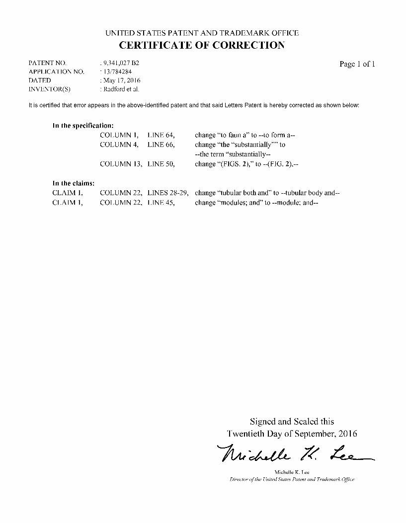
UNITED STATES PATENT AND TRADEMARK OFFICE
CERTIFICATE OF CORRECTION
PATENT NO. : 9,341,027 B2 Page 1 of 1 APPLICATION NO. 13/784284 DATED : May 17, 2016 INVENTOR(S) : Radford et al.
It is certified that error appears in the above-identified patent and that said Letters Patent is hereby corrected as shown below:
In the specification: COLUMN 1, LINE 64, change “to fauna to --to form a-- COLUMN 4, LINE 66, change “the “substantially” to
--the term “substantially COLUMN 13, LINE 50, change “(FIGS. 2), to --(FIG. 2).--
In the claims:
CLAIM1, COLUMN 22, LINES 28-29, change “tubular both and to -tubular body and-- CLAIM1, COLUMN 22, LINE 45, change “modules; and to -module; and--
Signed and Sealed this Twentieth Day of September, 2016
74-4-04- 2% 4 Michelle K. Lee
Director of the United States Patent and Trademark Office