TM - Concordia Universityconfsys.encs.concordia.ca/ICCM19/AllPapers/FinalVersion/KUR80132.pdf ·...
11
THE 19 TH INTERNATIONAL CONFERENCE ON COMPOSITE MATERIALS Abstract The applicability of C-ply Bi-angle TM Non-Crimp-Fabric (NCF) to aircraft parts was evaluated through the fabrication trial and strength tests of the representative stiffeners fabricated by autoclave cure. The strengths were evaluated through series of coupon tests and part compression tests. Impact damage resistance and its effect on the strengths were also evaluated. The thin ply, which is half the thickness of typical composite materials, conformed to the tool without local bridging or wrinkling, and contributed to the good quality of the parts. The impact damage and resulting strength reduction were similar to those of typical material consisting of thicker plies. The overall conclusion is that the C-ply Bi-angle TM NCF is a promising low cost option for long and continuous aircraft part such as stiffeners. 1 Introduction 1.1 Material System C-ply Bi-angle TM NCF (ref. [1]) is a Non-Crimp- Fabric material comprised of thin plies of carbon fiber stacked in two or more angles and stitched together by thin polyester fibers. In this study, the following material system was used. C-Ply BX0/+45 150 T3, 4 12K HS-AR2527- 153/35, 49.2" NCF fabricated by Chomarat using Toray T700 carbon fibers, which was then pre-impregnated by Aldila Composite Materials AR 2527 Epoxy Resin. The nominal ply thickness is 0.076 mm. Fig.1.1 shows the bag-side surface appearance of the laminate fabricated using this NCF material system which demonstrates the binding fibers. 0 degree fibers 45 degree fibers polyester binding fibers Fig.1.1 Material Appearance 1.2 Applicability to Composite Aircraft Part As with any new material systems being evaluated for applicability to aircraft parts, the following characteristics of the NCF material were evaluated. (1) Ease of fabrication (2) Laminate strength (3) Part strength (4) Impact resistance The NCF material is designed to simplify the labor intensive fabrication process (namely the cutting and layup process) and reduce the fabrication cost. The fabrication trials of coupon panels and representative parts will confirm the simplification of the fabrication process, and will also reveal unidentified fabrication issues. The laminate strength and part strength do not always match for thin aircraft parts. For example, aircraft parts subject to compressive load will fail by crippling at stress levels lower than the laminate compressive strengths. The crippling failure occurs when element(s) of the cross section, such as flanges or webs, buckles locally and increase the stress level of the remaining elements and corners. Typical aircraft parts are designed to allow local and stable buckling, and therefore its compressive strength is typically defined by the crippling failure. APPLICABILITY OF C-PLY BI-ANGLE TM NCF TO AIRCRAFT PARTS A. Kuraishi 1* , T. Itoh 1 , J. Kimoto 1 , S. Ochi 1 , N. Hirano 1 1 Aerospace Company, Kawasaki Heavy Industries, Ltd., Kakamigahara, Japan * Corresponding author ([email protected]) Keywords: aircraft, buckling, crippling, NCF
Transcript of TM - Concordia Universityconfsys.encs.concordia.ca/ICCM19/AllPapers/FinalVersion/KUR80132.pdf ·...

THE 19TH INTERNATIONAL CONFERENCE ON COMPOSITE MATERIALS
Abstract The applicability of C-ply Bi-angleTM Non-Crimp-Fabric (NCF) to aircraft parts was evaluated through the fabrication trial and strength tests of the representative stiffeners fabricated by autoclave cure. The strengths were evaluated through series of coupon tests and part compression tests. Impact damage resistance and its effect on the strengths were also evaluated. The thin ply, which is half the thickness of typical composite materials, conformed to the tool without local bridging or wrinkling, and contributed to the good quality of the parts. The impact damage and resulting strength reduction were similar to those of typical material consisting of thicker plies. The overall conclusion is that the C-ply Bi-angleTM NCF is a promising low cost option for long and continuous aircraft part such as stiffeners. 1 Introduction
1.1 Material System
C-ply Bi-angleTM NCF (ref. [1]) is a Non-Crimp-Fabric material comprised of thin plies of carbon fiber stacked in two or more angles and stitched together by thin polyester fibers. In this study, the following material system was used.
C-Ply BX0/+45 150 T3, 4 12K HS-AR2527-153/35, 49.2" NCF fabricated by Chomarat using Toray T700 carbon fibers, which was then pre-impregnated by Aldila Composite Materials AR 2527 Epoxy Resin. The nominal ply thickness is 0.076 mm.
Fig.1.1 shows the bag-side surface appearance of the laminate fabricated using this NCF material system which demonstrates the binding fibers.
0 degree fibers
45 degree fibers polyesterbinding fibers
Fig.1.1 Material Appearance
1.2 Applicability to Composite Aircraft Part
As with any new material systems being evaluated for applicability to aircraft parts, the following characteristics of the NCF material were evaluated.
(1) Ease of fabrication (2) Laminate strength (3) Part strength (4) Impact resistance
The NCF material is designed to simplify the labor intensive fabrication process (namely the cutting and layup process) and reduce the fabrication cost. The fabrication trials of coupon panels and representative parts will confirm the simplification of the fabrication process, and will also reveal unidentified fabrication issues.
The laminate strength and part strength do not always match for thin aircraft parts. For example, aircraft parts subject to compressive load will fail by crippling at stress levels lower than the laminate compressive strengths. The crippling failure occurs when element(s) of the cross section, such as flanges or webs, buckles locally and increase the stress level of the remaining elements and corners. Typical aircraft parts are designed to allow local and stable buckling, and therefore its compressive strength is typically defined by the crippling failure.
APPLICABILITY OF C-PLY BI-ANGLETM NCF TO AIRCRAFT PARTS
A. Kuraishi1*, T. Itoh1, J. Kimoto1, S. Ochi1, N. Hirano1
1 Aerospace Company, Kawasaki Heavy Industries, Ltd., Kakamigahara, Japan * Corresponding author ([email protected])
Keywords: aircraft, buckling, crippling, NCF

Impact resistance is also an important property for composite materials which are susceptible to interlaminar delamination due to impact. Since impact damage tends to leave little or no trace at the surface of a composite part, the design must accommodate certain level of damage that cannot be detected visually. The NCF material consists of thin plies, which is known to have higher resistance to impact. Therefore, the susceptibility to impact damage and the resulting strength reduction are evaluated.
1.3 Representative Aircraft Part
The stiffener is selected as the representative aircraft part since the benefit of the bi-angle NCF is most evident in the fabrication of long aircraft parts.
Typical fabrication process for the stiffeners using a uni-directional prepreg is as follows.
(1) Uni-directional prepreg is spread on a table and cut into pieces with designated angle and length.
(2) Each piece is laid side-by-side, such that the fibers are aligned and the gaps between the pieces are within the acceptable limit.
(3) Process (2) is repeated for each ply, which is stacked on top of the previous ply.
(4) Location of the splice, where the pieces meet side-by-side, is controlled such that they do not align in the thickness direction.
The layup process can be automated using automatic prepreg cutter, automatic tape layup (ATL) machine, or automatic fiber placement (AFP) machine, but remains to be time-consuming and expensive.
In contrast, long parts can be fabricated by simply stacking the NCF, which is pre-stacked in multiple angles. Typical fabrication process for long parts with width within the material width is as follows.
(1) The NCF prepreg is spread on a table and cut only in the longitudinal direction.
(2) The NCF prepregs are simply stacked up to the desired thickness.
No consideration on the splice locations or gaps is necessary during the fabrication. The process can be readily automated and significant time and cost reduction can be achieved.
The disadvantage of the NCF material is that it is difficult to splice side-by-side, since one or more pre-stacked layers will have fibers terminating at the edges. Lap splice is required to transfer the load through the fibers, but is effective only to a certain degree.
For these reasons, a stiffener was chosen as the representative part, which can be fabricated without splicing the material. A stiffener in the shape of a letter “I”, or I-beam, was selected since this configuration is widely used in composite aircraft parts, and since the fabrication of the I-beam poses certain level of difficulties.
Fig.1.2 shows the stiffener configuration chosen as the representative aircraft part.
93.4mm
60mm
Tool side Tool side
NCF [(45/0)/(0/-45)]5T
Filler (made of [0] of similar CFRP)
NCF [(45/0)/(0/-45)]5T
NCF [(45/0)/(0/-45)]5T
NCF [(45/0)/(0/-45)]5T
Drawing not to scale
R 4mm(TYP)
Fig.1.2 Representative Part Configuration
1.4 Selected Ply Orientation
NCF can be fabricated in wide range of layup including the quasi-isotropic layup (equal number of plies in 0o, 90o, 45o, -45o). For this study, a single type of bi-angle NCF consisting of only the 0o and 45o ply was used.
Both the test coupons and the stiffeners were fabricated in [45/0/0/-45]n layup, where n is an integer representing the repeat of four plies. [0/-45] is achieved by flipping over the [45/0] NCF.
The layup without the 90o ply was selected since it did not appear to be essential for long parts subject to mostly longitudinal loads.

3
APPLICABILITY OF C-PLY BI-ANGLE NCF TO AIRCRAFT PARTS
For this study, asymmetric layup was selected to evaluate whether the thin plies are less susceptible to twist and warp, and also this will allow low cost fabrication using only a single type of NCF rather than two types.
1.5 Impact
Selected coupon panels and stiffeners were subject to impact, and the reductions in the compressive strengths were measured. The impact level was defined such that the resulting damages were near the following damage thresholds from ref.[2].
BVID: Barely Visible Impact Damage Damage level which could be missed during visual
inspection at typical on-site inspection condition. The aircraft part with BVID must endure ultimate static load and have full fatigue life capability.
VID: Visible Impact Damage Damage level which will be detected by visual
inspection during the scheduled inspection. The part with VID must endure limit static load.
Impact damages were inflicted on two stiffeners at the critical locations; one part at the center of the web, and another part at the flange near the web intersection.
1.6 Reference Material for Comparison
The strengths of the coupon panels and the stiffeners fabricated using the NCF material were compared with those using the following reference material.
Toho-Tenax QU135-197A UT500 carbon fiber and #135 epoxy resin Resin content is 35% in weight Nominal ply thickness 0.19 mm
This material system meets the material specification certified by the regulatory authorities and is used to fabricate commercial aircraft parts. This material was chosen as a reference, since the Toho-Tenax UT500 carbon fibers are comparable to the Toray T700 carbon fibers used in the NCF material. The cure temperature of the reference material is 180oC, in contrast to 135oC for the NCF material.
The reference stiffener, with the same dimension as the stiffener defined in Fig.1.2, was fabricated using the reference material. The ply orientation was chosen such that the thickness is the same, and that the part has 43% 0o, 43% +/-45o and 14% 90o plies. This is a typical ply orientation for a stiffener, which is designed with high percentage of 0o plies and lower but non-zero percentage of plies in other directions. In contrast, the NCF part has 50% 0o, 50% +/-45o plies and no 90o ply.
Both materials are autoclave cured and consist of comparable carbon fibers. Therefore, the NCF stiffener is expected to have higher longitudinal strength than the reference stiffener with less percentage of 0o and +/-45o plies.
2 Fabrication
2.1 Fabrication of the Panels
Panels were fabricated to confirm the basic process parameters provided to the authors from the resin manufacturer, Aldila Composite Materials, and also to fabricate the test coupons.
Typical aircraft part fabrication process was adopted, namely (1) the layup process in a controlled contamination area, (2) frequent compaction by vacuum during the layup, and (3) autoclave cure.
The NCF material was easy to work with, and no difficulty was encountered during the fabrication.
On the other hand, the following anomalies were observed in the finished panels.
- Warp of the panel
- Thickness deviations up to 10%
Fig.2.1 shows the warp of the panel. The warp is caused from the thermal residual stress which did not cancel because of the asymmetric layup. This was contrary to the expectation that the asymmetry will be eased by stacking the thin plies in sufficient repeats. Nonetheless, this issue is easily resolved with the symmetric layup, which will require two layup types of NCF instead of one.

Fig.2.2 shows the panel cross section where the thickness varied the most from the nominal thickness of 2.43mm. The figure demonstrates that the panel thickness deviation is caused by the non-uniform thickness of the consisting plies. The thickness variation is less evident on other panels and stiffeners, whose thickness variations of the consisting plies averaged out and resulted in more uniform laminate thickness. Nonetheless, improved material thickness uniformity is necessary to eliminate the risk of excessive thickness deviation of the finished product.
Fig.2.3 shows the microscopic observation of the cross section of the panels, which indicate good internal quality with no observable delamination, voids or fiber warpage. The measured porosity level was 0.2% in this cross section.
Fig.2.1 Fabricated Panel and its Warp
Fig.2.2 Maximum Thickness Deviation
Fig.2.3 Microscopic Observation
2.2 Fabrication of the Stiffeners
Stiffeners with the configuration defined in Fig. 1.2 were fabricated using the NCF material and typical fabrication process outlined in section 2.1. Fig.2.4 shows one of the fabricated stiffeners.
The fabrication tool consists of two aluminum blocks and caul plates for the flanges. Fig.1.2 shows how the prepregs are stacked in four groups and assembled to form the I-shape. The two intersections of web and flanges were filled with the uni-directional prepreg of the reference material. The filler material should be the same as the rest of the part, but this will require a uni-directional prepreg in addition to the bi-angle NCF prepreg.
The fabrication trial demonstrated the ease of fabrication with the contribution from both the layup and the material system. The tack of the resin and the stiffness of the backing paper contributed to the ease of layup by stabilizing the NCF of two thin plies. The layup without the 90o ply contributed to good conformance to the tool without any bridging or wrinkling at the corners typically caused by the 90o fibers.
Fig.2.5 shows an example of the cross section observation of the stiffener at the intersection of the flange and the web. This and other cross section observations of the finished parts did not reveal any flaws in the layup including the corners. Certain level of thickness variation exists, but within an acceptable level. Neither obvious ply distortion nor wrinkling was observed. The corner filler and the surrounding plies conformed well to the tool radius.
On the other hand, Fig.2.6 shows the twist of the stiffeners, which is apparent from the location of the flange ends. The part twisted due to the thermal residual stress, despite the expectation that the effect of asymmetry will be reduced by stacking the thin plies in sufficient repeats. This twist can be reduced by designing the layup to be symmetric, but it should be noted that perfect symmetry is not possible for the I-beam configuration. Typically, the web and one half of the upper and lower flanges are designed to be symmetric, which result in negligible twist. Again, two types of NCF are required to create this mostly symmetric configuration.
warp

5
APPLICABILITY OF C-PLY BI-ANGLE NCF TO AIRCRAFT PARTS
Overall conclusions of the stiffener fabrication trial are the following.
- The ease of fabrication was demonstrated.
- Good part quality was achieved.
- Asymmetry will lead to part warp and twist and should be avoided.
Fig.2.4 Fabricated Stiffener
Fig.2.5 Cross Section of the Stiffener
Fig.2.6 Twist of the Stiffener
2.3 Impact Application
Selected coupon panels and stiffeners were subject to impact at the critical locations.
Fig.2.7 shows the equipment used to apply accurate impact energy to the panels. The impact to the stiffeners was applied in the similar manner. Steel indenters with 16mm diameter were used for both the panels and the stiffeners.
After each impact, the following measurements were performed.
- Depth measurement of the dent on the surface
- Non-destructive Technique (NDT) measurement of the delamination size
Fig.2.8 shows the typical impact damage of the panel, which is characterized by a small dent on the surface. The impact damage was neither more nor less apparent than that of the reference material, although the undamaged surface appearance of the NCF (as shown in Fig.1.1) is different from the reference material.
twist evident from location of flange ends

Fig.2.9 shows the corresponding NDT results indicating significant delamination around the impact location. The damaged area is similar in size to those inflicted on the reference material with the same level of impact energy.
The impact application tests showed that the relation between the impact energy and the resulting dent and delamination were similar to the relation for the reference material. Therefore, the NCF material did not demonstrate the anticipated impact resistance improvement due to the thin plies. This may not be a fair comparison, since the reference material uses aircraft grade tough epoxy resin which may have compensated the disadvantage of the thicker plies.
Fig.2.7 Impact Application Equipment
Fig.2.8 Typical Impact Damage Appearance
Fig.2.9 Typical NDT Result
3 Strengths Evaluation
3.1 Coupon Tests
Series of coupon tests were performed to evaluate the basic laminate properties of the NCF material. The test results were compared with the analytical prediction described in Section 4.1.
Fig.3.1 and Fig.3.2 show the results of the following coupon tests. The bar represents the average strengths, and the error bars indicate the maximum and minimum values from the tests of three to six repeats.
UNT: Un-Notched Tension (ASTM D3039) ILSS: Inter-Laminar Shear Strength
(ASTM D2344) UNC: Un-Notched Compression (SACMA SRM3) OHC: Open Hole Compression (ASTM D6484) CAI: Compression After Impact (SACMA SRM2)
7
APPLICABILITY OF C-PLY BI-ANGLE NCF TO AIRCRAFT PARTS
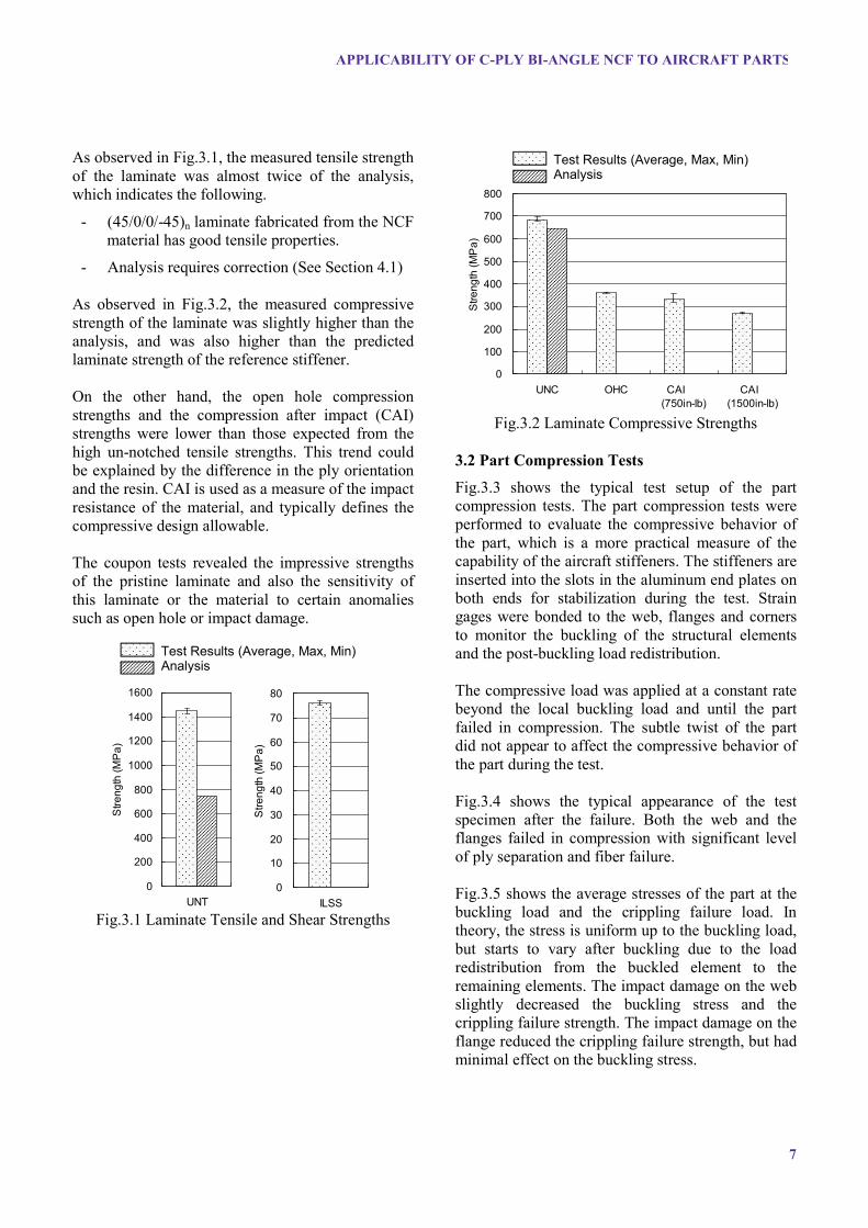
As observed in Fig.3.1, the measured tensile strength of the laminate was almost twice of the analysis, which indicates the following.
- (45/0/0/-45)n laminate fabricated from the NCF material has good tensile properties.
- Analysis requires correction (See Section 4.1)
As observed in Fig.3.2, the measured compressive strength of the laminate was slightly higher than the analysis, and was also higher than the predicted laminate strength of the reference stiffener.
On the other hand, the open hole compression strengths and the compression after impact (CAI) strengths were lower than those expected from the high un-notched tensile strengths. This trend could be explained by the difference in the ply orientation and the resin. CAI is used as a measure of the impact resistance of the material, and typically defines the compressive design allowable.
The coupon tests revealed the impressive strengths of the pristine laminate and also the sensitivity of this laminate or the material to certain anomalies such as open hole or impact damage.
0
200
400
600
800
1000
1200
1400
1600
UNT
Stre
ngth
(MP
a)
0
10
20
30
40
50
60
70
80
ILSS
Stre
ngth
(MP
a)
Fig.3.1 Laminate Tensile and Shear Strengths
0
100
200
300
400
500
600
700
800
UNC OHC CAI (750in-lb)
CAI (1500in-lb)
Stre
ngth
(MP
a)
Fig.3.2 Laminate Compressive Strengths
3.2 Part Compression Tests
Fig.3.3 shows the typical test setup of the part compression tests. The part compression tests were performed to evaluate the compressive behavior of the part, which is a more practical measure of the capability of the aircraft stiffeners. The stiffeners are inserted into the slots in the aluminum end plates on both ends for stabilization during the test. Strain gages were bonded to the web, flanges and corners to monitor the buckling of the structural elements and the post-buckling load redistribution.
The compressive load was applied at a constant rate beyond the local buckling load and until the part failed in compression. The subtle twist of the part did not appear to affect the compressive behavior of the part during the test.
Fig.3.4 shows the typical appearance of the test specimen after the failure. Both the web and the flanges failed in compression with significant level of ply separation and fiber failure.
Fig.3.5 shows the average stresses of the part at the buckling load and the crippling failure load. In theory, the stress is uniform up to the buckling load, but starts to vary after buckling due to the load redistribution from the buckled element to the remaining elements. The impact damage on the web slightly decreased the buckling stress and the crippling failure strength. The impact damage on the flange reduced the crippling failure strength, but had minimal effect on the buckling stress.
Test Results (Average, Max, Min) Analysis
Test Results (Average, Max, Min) Analysis

Fig.3.6 shows the average buckling and crippling failure stresses of the reference stiffener for comparison purpose.
The test revealed that the NCF stiffeners have lower buckling and crippling failure stresses than the reference stiffener despite having higher laminate compressive strength. Possible reason for the lower part strength will be studied in Section 4.2.
Fig.3.3 Part Compression Test Configuration
Fig.3.4 Failure Mode of the Part
0
50
100
150
200
250
300
350
400
Pristine#1
Pristine#2
FlangeImpact
Web Impact
Ave
rage
Stre
ss (M
Pa)
FailureBuckling
Fig.3.5 Stiffener Compressive Strength
0
50
100
150
200
250
300
350
400
Pristine #1 Pristine #2 FlangeImpact
Web Impact
Ave
rage
Stre
ss (M
Pa)
FailureBuckling
Fig.3.6 Reference Stiffener Compressive Strength

9
APPLICABILITY OF C-PLY BI-ANGLE NCF TO AIRCRAFT PARTS
4 Analytical Evaluation
4.1 Lamina Strength Evaluation
Since the NCF material is provided in the bi-angle stitched form, the lamina properties (orthogonal properties of a single ply) of the NCF material could not be obtained from the test. Therefore, the lamina properties were estimated from the laminate strength measurements in Section 3.1 combined with the Tsai-Wu first-ply-failure (FPF) criterion. For a laminate that continues to carry load after the FPF, progressive damage analysis is required to evaluate the final failure. Tsai et al (ref.[1]) have reported that for the laminate fabricated from the bi-angle NCF, FPF is equal to the final failure. Using this observation, lamina strength was estimated from the measured laminate strengths in tension (UNT) and compression (UNC).
Table 4.1 shows the values of the lamina properties provided by Tsai et al (ref.[1]) from various tests and analysis coordinated by Stanford University. These values were used to analyze the laminate strength shown in Fig.3.1 and Fig.3.2.
Using the Tsai-Wu FPF failure criterion, the values of the following key lamina properties were adjusted as shown in Table 4.1 such that the calculated laminate strengths matched the UNT and UNC test results.
X: longitudinal tensile strength X’: longitudinal compressive strength Y: transverse tensile strength S: shear strength
Fig.4.1 and Fig4.2 show the estimated lamina strengths compared with the baseline values provided by Stanford University, and those of the reference material. The estimated lamina strengths were equivalent or higher than those of the reference material. Considering that both materials consist of comparable carbon fibers, it is natural to conclude the following.
- The lamina properties of NCF material are comparable to the reference material
- The actual laminate strengths were stronger than those predicted by the Tsai-Wu FPF failure criterion
Table 4.1 Provided and Estimated Lamina Data
Properties Stanford Estimation Modulus (GPa)
Longitudinal Ex 121.0 121.0 Transverse Ey 8.0 8.0
Strength (MPa) Long. Tension X 2530 2850 Long. Comp. X' 1669 1669 Trans. Tension Y 66 80 Trans. Comp. Y' 220 220 Shear S 93 188
0
500
1000
1500
2000
2500
3000
X X'
Stre
ngth
s (M
Pa)
Estimation from TestStanford DataReference Material
Fig.4.1 Estimated Lamina Strengths (Fiber related properties)
0
20
40
60
80
100
120
140
160
180
200
Y S
Stre
ngth
s (M
Pa)
Estimation from Test
Stanford Data
Reference Material
Fig.4.2 Estimated Lamina Strengths (Matrix related properties)

4.2 Buckling Analysis of the Stiffeners
The analytical buckling stress was calculated based on the following equations defined in Composite Materials Handbook - 17 Volume 3 (ref.[3], CMH-17-3G).
For the flange buckling stress with three simply supported edges and one free edge, the following equation (Eq.9.2.1.5 in CMH-17-3G) applies.
211
2
266
,12
aD
bD
N crclx
(4.1)
For the web buckling stress with two loaded edges simply supported and two unloaded edges fixed, the following equation (Eq.9.2.1.7 in CMH-17-3G) applies. Here, m and n are chosen to minimize N.
6622
221222
11266
, )/1()/(33.567.2/12 DmbaDDabmDbDN cr
clx
(4.2)
For the web buckling stress with all edges simply supported, the following equation (Eq.9.2.1.6 in CMH-17-3G) applies. Again, m and n are chosen to minimize N.
22
422
2226612
4411
2
2
, )/()/()2(2/
abmnDabnmDDabmD
bN cr
clx
(4.3)
Fig.4.3 shows the predicted and measured buckling stress from the part compression test of Section 3.2 for both the NCF part and the reference part. The figure demonstrates that the actual buckling stresses match the predicted flange buckling stresses. Also note that the actual web buckling stress was higher than the prediction assuming simple support, and lower than that assuming fixed boundary conditions (BC) at both sides of the web supported by the flanges. It can be assumed that the un-buckled flanges support the web as a fixed BC, whereas the buckled flange will twist and is closer to a simple support BC.
In the test, the web and flange buckled at the same load, which can be assumed as the flange buckling initiated first, which reduced the BC of the web edges such that the web buckling followed.
Also observed in Fig.4.3 is that the NCF stiffener has lower buckling stress than the reference stiffener despite having higher laminate compressive strength.
For the NCF stiffener, the first term of Eq.4.1 accounts for 96% of the total, meaning that the buckling load is a strong function of torsion stiffness D66. The D66 of the NCF stiffener is lower than that of the reference stiffener, thus resulting in lower buckling stress. The D66 of the NCF stiffener is low not because of the ply orientation, but because of the low shear modulus of the material.
0
50
100
150
200
250
300
350
400
NC
F Te
st #
1
NC
F Te
st #
2
Ana
lysi
s Fl
ange
Ana
lysi
s W
eb S
S
Ana
lysi
s W
eb F
ixed
Ref
Tes
t #1
Ref
Tes
t #2
Ana
lysi
s Fl
ange
Ana
lysi
s W
eb S
S
Ana
lysi
s W
eb F
ixed
Ave
rage
Stre
ss (M
Pa)
Fig.4.3 Measured and Estimated Buckling Stress
4.3 Crippling Failure Analysis of the Stiffeners
The crippling stress of the flange is calculated from Fig.9.2.2.3(a) in CMH-17-3G. The horizontal axis of the figure is a non-dimension value defined in Eq.9.2.2.2, which is repeated below.
yx
cu
x EEF
tEEb
where yxxytDE 1123
11 (4.4)
NCF Stiffener Reference Stiffener

11
APPLICABILITY OF C-PLY BI-ANGLE NCF TO AIRCRAFT PARTS
The crippling stress of the part is calculated by taking a weighted average of the individual section of the part, as defined in Eq.9.2.2.3 of CMH-17-3G, which is repeated below.
N
iii
N
iii
cci
ccST
tb
tbFF
1
1 (4.5)
Fig.4.4 shows the predicted crippling failure stress and the measurement from the part compression test of Section 3.2 for both the NCF part and the reference part. Fig.4.4 demonstrates that the actual failure stress is higher than the predicted failure stress. The weighted average (“overall” in Fig.4.4) was even lower. These results are not surprising since most equations provide conservative failure predictions.
Note that Eq.4.4 includes the term transverse modulus Ey, which in effect leads to lower crippling failure stress for lower Ey. The NCF part has lower Ey due to the lack of the 90o ply and results in lower crippling failure stress prediction. The test results confirmed this trend.
0
50
100
150
200
250
300
350
400
NC
F Te
st #
1
NC
F Te
st #
2
Ana
lysi
s Fl
ange
Ana
lysi
s O
vera
ll
Ref
Tes
t #1
Ref
Tes
t #2
Ana
lysi
s Fl
ange
Ana
lysi
s O
vera
ll
Ave
rage
Stre
ss (M
Pa)
Fig.4.4 Measured and Estimated Crippling Stress
6 Conclusion
The fabrication trial demonstrated that the C-ply Bi-angleTM NCF is suitable for long aircraft parts such as stiffeners. The thin plies conformed well to the tool and contributed to the good quality of the parts. Not clear was the improved resistance to impact damage, which is typically expected from the thin plies. For parts requiring high dimensional accuracy, the asymmetric layup should be avoided.
The NCF material demonstrated impressive lamina and laminate strengths comparable to the aircraft grade material with higher cure temperature. The [45/0/0/-45]n layup demonstrated high longitudinal strength as a laminate, but lower compressive strength as a part. The analytical evaluation indicated the following two causes.
- low shear modulus of the material, which reduced the torsion stiffness of the flanges, which in turn reduced the local buckling load
- lack of 90o ply, which reduced the transverse bending stiffness of the flanges, which in turn reduced the crippling failure load
The above drawbacks can be improved by increasing the shear strengths of the resin, and by adding few layers of NCF with 90o ply.
The overall conclusion is that the C-ply Bi-angleTM
NCF is a promising low cost material options for the aircraft parts.
The authors would like to thank Stanford University, Chomarat, Aldila Composite Materials, VX Aerospace and MAG for providing the material and the material data for this study.
References [1] S. W. Tsai, “C-Ply Fabric for anisotropic, asymmetric
laminates”. Proceedings of Innovative Composites Summit (JEC Americas 2012), Boston, USA, 2012.
[2] M. Mohaghegh, “Validation and Certification of Aircraft Structures”. 46th AIAA/ASME/ASCE/AHS/ ASC Structures, Structural Dynamics & Materials Conference, Austin, USA, 2005
[3] “Composite Materials Handbook - 17”. SAE Int’l / Wichita State University, 2012
NCF Stiffener Reference Stiffener


![MODELING STRUCTURAL BEHAVIOUR OF PVC …confsys.encs.concordia.ca/ICCM19/AllPapers/FinalVersion/...absorption of circular CFRP tubes with diameter/thickness ratio [7] (b) Photograph](https://static.fdocuments.us/doc/165x107/5adb09867f8b9a6d318d8ddd/modeling-structural-behaviour-of-pvc-of-circular-cfrp-tubes-with-diameterthickness.jpg)