TM 55-1680-308-24 TECHNICAL MANUAL ...TM 55-1680-308-24 TECHNICAL MANUAL ORGANIZATIONAL, DS AND GS...
192
TM 55-1680-308-24 TECHNICAL MANUAL ORGANIZATIONAL, DS AND GS MAINTENANCE MANUAL EJECTION SEAT, MODEL MK-J5D (MARTIN-BAKER) PART NUMBER 134AB80000 This copy is a reprint which includes current pages from Changes 1 through 10. TM 55-1680-308-24, dated 13 December 1974, rescinded by DA Pam 310-1, is now reinstated for active Army and is available through normal supply channels. HEADQUARTERS, DEPARTMENT OF THE ARMY 13 DECEMBER 1974
Transcript of TM 55-1680-308-24 TECHNICAL MANUAL ...TM 55-1680-308-24 TECHNICAL MANUAL ORGANIZATIONAL, DS AND GS...

TM 55-1680-308-24
TECHNICAL MANUAL
ORGANIZATIONAL, DS AND GS MAINTENANCE MANUAL
EJECTION SEAT, MODEL MK-J5D
(MARTIN-BAKER)
PART NUMBER 134AB80000
This copy is a reprint which includes currentpages from Changes 1 through 10.
TM 55-1680-308-24, dated 13 December1974, rescinded by DA Pam 310-1, is nowreinstated for active Army and is availablethrough normal supply channels.
HEADQUARTERS, DEPARTMENT OF THE ARMY 13 DECEMBER 1974

This manual is published for the use of all concerned.
By Order of the Secretary of the Army
FRED C. WEYANDOfficial General. United States Army
VERNE L. BOWERS Chief of StaffMajor General, United States Army
The Adjutant General
DISTRIBUTION:To be distributed in accordance with DA Form 12-31 Organizational Maintenance Requirements for OV-1A, B and
C, and OV-1D aircraft.

TM 55-1680-308-24URGENT C 10
CHANGE HEADQUARTERSDEPARTMENT OF THE ARMY
NO. 10 WASHINGTON, D.C., 14 May 1991
ORGANIZATIONAL, DS AND GS MAINTENANCE MANUAL
EJECTION SEAT, MODEL MK-J5D
(MARTIN-BAKER)
PART NUMBER 134AB80000
TM 55-1680-308-24, 13 December 1974, is changed as follows:
1. Remove and insert pages as indicated below. New or changed text material is indicated by a vertical bar in themargin. An illustration change is indicated by a miniature pointing hand.
Remove pages Insert pages
i and ii i and ii1-1 and 1-2 1-1 and 1-23-1 and 3-2 3-1 and 3-24-47 and 4-48 4-47 and 4-484-48A/4-48B 4-48A/4-48B
2. Retain this sheet in front of manual for reference purposes.
By Order of the Secretary of the Army:
CARL E. VUONOGeneral, United States Army
Official: Chief of Staff
PATRICIA P. HICKERSONColonel, United States Army
The Adjutant General
DISTRIBUTION:To be distributed in accordance with DA Form 12-31-E, block no. 1102, AVUM and AVIM maintenance
requirements for TM 55-1680-308-24.
URGENT
}

TM 55-1680-308-24C 9
CHANGE HEADQUARTERSDEPARTMENT OF THE ARMY
NO. 9, WASHINGTON, D.C., 17 April 1990
ORGANIZATIONAL, DS AND GS MAINTENANCE MANUAL
EJECTION SEAT, MODEL MK-J5D
(MARTIN-BAKER)
PART NUMBER 134AB80000
TM 55-1680-308-24, 13 December 1974, is changed as follows:
1. Remove and insert pages as indicated below. New or changed text material is indicated by a vertical bar in themargin. An illustration change is indicated by a miniature pointing hand.
Remove pages Insert pages
4-47 and 4-48 4-47 and 4-484-48A/4-48B 4-48A/4-48B
2. Retain this sheet in front of manual for reference purposes.
By Order of the Secretary of the Army:
CARL E. VUONOGeneral, United States Army
Official: Chief of Staff
WILLIAM J MEEHAN IIBrigadier General, United States Army
The Adjutant General
DISTRIBUTION:To be distributed in accordance with DA Form 12-31, AVUM and AVIM Maintenance requirements for OV-1B, OV-1C,OV-1D, Airplane, Observation and RV-1D, Airplane Reconnaissance.
}

TM 55-1680-308-24C8
CHANGE HEADQUARTERSDEPARTMENT OF THE ARMY
NO. 8 WASHINGTON, D.C., 4 October 1988
ORGANIZATIONAL, DS AND GS MAINTENANCE MANUAL
EJECTION SEAT, MODEL MK-J5D
(MARTIN-BAKER)
PART NUMBER 134AB8000
TM 55-1680-308-24, 13 December 1974, is changed as follows:
1. Remove and insert pages as indicated below. New or changed text material is indicated by a vertical bar in themargin. An illustration change is indicated by a miniature pointing hand.
Remove pages Insert pages
i and ii i and ii1-1 and 1-2 1-1 and 1-21-15 and 1-16 1-15 and 1-164-1 and 4-2 4-1 and 4-24-2A/4-2B 4-2A/4-2B4-16A and 4-16B 4-16A and 4-16B4-17 and 4-18 4-17 and 4-184-37 and 4-38 4-37 and 4-384-41 and 4-42 4-41 and 4-424-51 and 4-52 4-51 and 4-52--------- 4-52.1/4-52.24-55 through 4-58 4-55 through 4-585-31 and 5-32 5-31 and 5-32--------- 5-32.1/5-32.25-49 and 5-50 5-49 and 5-50A-1/A-2 A-1/A-2
2. Retain this sheet in front of manual for reference purposes.
}

TM 55-1680-308-24C 8
By Order of the Secretary of the Army:
CARL E. VUONOGeneral, United States Army
Official: Chief of Staff
WILLIAM J. MEEHAN IIBrigadier General, United States Army
The Adjutant General
DISTRIBUTION:To be distributed in accordance with DA Form 12-31, AVUM and AVIM Maintenance requirements for OV-1B, OV-1C,OV-1D, Airplane, Observation and RV-1D, Airplane, Reconnaissance.

TM 55-1680-308-24
URGENT C 7
CHANGE HEADQUARTERSDEPARTMENT OF THE ARMY
NO. 7 WASHINGTON, D.C., 30 December 1987
ORGANIZATIONAL, DS AND GS MAINTENANCE MANUAL
EJECTION SEAT, MODEL MK-J5D
(MARTIN-BAKER)
PART NUMBER 134AB8000
TM 55-1680-308-24, 13 December 1974, is changed as follows:
1. Remove and insert pages as indicated below. New or changed text material is indicated by a vertical bar in themargin. An illustration change is indicated by a miniature pointing hand.
Remove pages Insert pages
3-1 and 3-2 3-1 and 3-24-35 and 4-36 4-35 and 4-364-55 and 4-56 4-55 and 4-56----- 4-56.1/4-56.2
2. Retain this sheet in front of manual for reference purposes.
By Order of the Secretary of the Army:
CARL E. VUONOGeneral, United States Army
Chief of Staff
R. L. DILWORTHBrigadier General, United States Army
The Adjutant General
DISTRIBUTION:To be distributed in accordance with DA Form 12-31, AVUM and AVIM Maintenance requirements for OV-1B, OV-1C,OV-1D, Airplane, Observation, and RV-1D, Airplane, Reconnaissance.
URGENT
}
TM 55-1680-308-24C 6
CHANGE HEADQUARTERSDEPARTMENT OF THE ARMY
NO. 6 WASHINGTON, D.C., 24 June 1987
ORGANIZATIONAL, DS AND GS MAINTENANCE MANUAL
EJECTION SEAT, MODEL MK-J5D
(MARTIN-BAKER)
PART NUMBER 134B80000
TM 55-1680-308-24, 13 December 1974, is changed as follows:
1. Remove and insert pages as indicated below. New or changed text material is indicated by a vertical bar in themargin. An illustration change is indicated by a miniature pointing hand.
Remove pages Insert pages
1-1 and 1-2 1-1 and 1-24-37 and 4-38 4-37 and 4-384-47 and 4-48 4-47 and 4-484-48A/(4-48B) 4-48A/(4-48B)4-57 and 4-58 4-57 and 4-585-45 and 5-46 5-45 and 5-46A-1/(A-2) A-1/(A-2)C-1 and C-2 C-1 and C-2
2. Retain this sheet in front of manual for reference purposes.
By Order of the Secretary of the Army:
JOHN A. WICKHAM, JR.General, United States Army
Official: Chief of Staff
R. L. DILWORTHBrigadier General, United States Army
The Adjutant General
DISTRIBUTION:To be distributed in accordance with DA Form 12-31, AVUM and AVIM Maintenance requirements for OV-1B, OV-1C,OV-1D, Airplane, Observation, and RV-1D, Airplane, Reconnaissance.
}

TM 55-1680-308-24C 5
CHANGE HEADQUARTERSDEPARTMENT OF THE ARMY
NO. 5 WASHINGTON, D.C., 30 May 1985
ORGANIZATIONAL, DS AND GS MAINTENANCE MANUAL
EJECTION SEAT, MODEL MK-J5D
(MARTIN-BAKER)
PART NUMBER 134AB80000
TM 55-1680-308-24, 13 December 1974, is changed as follows:
1. Remove and insert pages as indicated below. New or changed text material is indicated by a vertical bar in themargin. An illustration change is indicated by a miniature pointing hand.
Remove pages Insert pages
i and ii i and ii1-1 and 1-2 1-1 and 1-21-17 and 1-18 1-17 and 1-183-1 and 3-2 3-1 and 3-2--- 3-2A/3-2B4-1 and 4-2 4-1 and 4-2--- 4-2A/4-2B4-31 and 4-32 4-31 and 4-324-45 and 4-46 4-45 and 4-46--- 4-46A/4-46B4-47 through 4-48A/4-48B 4-47 through 4-48A/4-48B4-51 and 4-52 4-51 and 4-524-57 and 4-58 4-57 and 4-585-9 and 5-10 5-9 and 5-105-37 and 5-38 5-37 and 5-38
2. Retain this sheet in front of manual for reference purposes.
By Order of the Secretary of the Army:
JOHN A. WICKHAM, JR.General, United States Army
Official: Chief of Staff
DONALD J. DELANDROBrigadier General, United States Army
The Adjutant General
DISTRIBUTION:To be distributed in accordance with DA Form 12-31, Organization, Direct Support and General Support
Maintenance requirements for OV-1B/C and OV-1D/RV-1D aircraft.
}

TM 55-1680-308-24C 4
CHANGE HEADQUARTERSDEPARTMENT OF THE ARMY
NO. 4 WASHINGTON, D.C., 9 October 1982
ORGANIZATIONAL, DS AND GS MAINTENANCE MANUAL
EJECTION SEAT, MODEL MK-J5D
(MARTIN-BAKER)
PART NUMBER 134AB80000
TM 55-1680-308-24, 13 December 1974, is changed as follows:
1. Remove and insert pages as indicated below.
Remove pages Insert pages
Table of Contents 1 and ii i and iiChapter 1 1-1 and 1-2 1-1 and 1-2Chapter 3 3-1 and 3-2 3-1 and 3-2
3-5 and 3-6 3-5 and 3-6Chapter 4 4-1 and 4-2 4-1 and 4-2
4-15 and 4-16 4-15 thru 4-16B4-23 and 4-24 4-23 and 4-244-47 and 4-48 4-47 and 4-484-57 and 4-58 4-57 and 4-58
Chapter 5 5-5 and 5-6 5-5 and 5-65-11 and 5-12 5-11 and 5-12
Appendix A A-1/A-2 A-1/A-2
2. New or changed text material is indicated by a vertical bar in the margin. An illustration change is indicatedby a miniature pointing hand.
3. Retain this sheet in front of manual for reference purposes
By Order of the Secretary of the Army:
E. C. MEYERGeneral, United States Army
Official: Chief of Staff
ROBERT M. JOYCEMajor General, United States Army
The Adjutant General
DISTRIBUTION:To be distributed in accordance with DA Form 12-31, Organizational Maintenance Requirements for OV-1B/C and
OV-1D/RV-1D Aircraft.
}
TM 55-1680-308-24C 3
CHANGE HEADQUARTERSDEPARTMENT OF THE ARMY
No. 3 WASHINGTON, D.C., 18 May 81
ORGANIZATIONAL, DS AND GS MAINTENANCE MANUAL
EJECTION SEAT, MODEL MK-J5D
(MARTIN-BAKER)
PART NUMBER 134AB80000
TM 55-1680-308-24, 13 December 1974 is changed as follows:
1. Remove and insert pages as indicated below.
Remove pages Insert pagesi and ii i and ii
Chapter 1 1-1 and 1-2 1-1 and 1-21-5 and 1-6 1-5 and 1-61-11 and 1-12 1-11 and 1-121-15 and 1-16 1-15 and 1-16
Chapter 3 3-1 and 3-2 3-1 and 3-2Chapter 4 4-1 and 4-2 4-1 and 4-2
4-5 and 4-6 4-5 and 4-64-15 thru 4-18 4-15 thru 4-184-23 and 4-24 4-23 and 4-244-27 and 4-28 4-27 and 4-284-31 and 4-32 4-31 and 4-324-45 thru 4-48B 4-45 thru 4-48A/B4-49 thru 4-52 4-49 thru 4-524-57 and 4-58 4-57 and 4-58
Chapter 5 5-3 and 5-4 5-3 and 5-45-39 and 5-40 5-39 and 5-40
2. New or changed text material is indicated by a vertical bar in the margin.An illustration change is indicated by a miniature pointing hand.
3. Retain this sheet in front of manual for reference purposes.
By Order of the Secretary of the Army:
E. C. MEYERGeneral, United States Army
Official: Chief of Staff
J. C. PENNINGTONMajor General, United States Army
The Adjutant General
DISTRIBUTION:To be distributed in accordance with DA Form 12-31, Organizational Maintenance Requirements for OV-1B/C and
OV-1D/RV-1D aircraft.
}

TM 55-1680-308-24C 2
CHANGE HEADQUARTERSDEPARTMENT OF THE ARMY
No. 2, WASHINGTON, DC., 17 January 1980
Organizational, DS and GS Maintenance Manual
EJECTION SEAT, MODEL MK-J5D(MARTIN-BAKER)
PART NUMBER 134AB80000
TM 55-1680-308-24, 13 December 1974, is changed as follows:
1. Remove and insert pages as indicated below.
Remove pages Insert pages
Table of Contents i and ii i and iiChapter 1 1-1 and 1-2 1-1 and 1-2
1-17 thru 1-19/1-20 1-17 thru 1-20Chapter 3 3-1 and 3-2 3-1 and 3-2Chapter 4 4-1 and 4-2 4-1 and 4-2
4-15 and 4-16 4-15 thru 4-16B4-17 thru 4-24 4-17 thru 4-24A/4-24B4-25 and 4-26 4-25 thru 4-26A/4-26B4-29 and 4-30 4-29 and 4-304-33 thru 4-34A/4-34B 4-33 and 4-344-37 thru 4-44 4-37 thru 4-444-47 and 4-48 4-47 thru 4-48B4-51 and 4-52 4-51 and 4-52
Chapter 5 5-3 and 5-4 5-3 and 5-45-9 thru 5-12 5-9 thru 5-125-33 thru 5-38 5-33 thru 5-38BBack of Manual DA Forms 2028
2. New or changed text material is indicated by a vertical bar in the margin.An illustration change is indicated by a miniature pointing hand.
3. Retain this sheet in front of manual for reference purposes.
By Order of the Secretary of the Army:
E C. MEYERGeneral, United States Army
Official: Chief of Staff
J. C. PENNINGTONMajor General, United State Army
The Adjutant General
DISTRIBUTION:To be distributed in accordance with DA Form 12-31 Organizational Maintenance Requirements for OV-1B/C and
OV-1D/RV-1D aircraft.
}

TM 55-1680-308-24
WARNING
PRECAUTIONARY DATA
Personnel performing operations, procedures, and practices which are included or implied in this technical manual shallobserve the following warnings. Disregard of these warnings and precautionary information can cause serious injury,death, or destruction of material.
MAINTENANCE
Only authorized personnel may perform work on this ejection seat and only in an authorized area. Ensure that TCRrocket motor locking pin is installed before removing seat from the aircraft.
Ensure that ground lock safety pins are installed unless preparing the aircraft for a mission or performing authorizedmaintenance on components of the ejection seat requiring removal of safety pins.
No attempt shall be made by organizational maintenance personnel to service the personnel parachute or drogueparachute.
CARTRIDGES
Primary cartridge O-ring is a special type and the correct type must be used. There is no serviceable substitute.
Never remove firing pin sear from primary firing mechanism until primary cartridge has been removed from primarycartridge breech.
When removing or installing firing cables (thick and thin) from firing pin sear of ejection gun primary firing mechanism,ensure firing pin sear safety pin is installed.
Use extreme caution when removing and handling primary, drogue and guillotine cartridges. These cartridges have apercussion-type primer cap (See TM 9-1300-206).
The auxiliary cartridges do not contain percussion-type primer caps, but are filled with an explosive powder which can beaccidentally fired by either spark or flame.
DROGUE GUN
Use extreme caution when removing drogue gun barrel to prevent dropping the drogue gun cartridge.
Ensure that drogue firing pin does not protrude above bottom surface of firing body hole.
FACE BLIND
Operational check of the face blind should only be accomplished when the ejection seat has been disarmed.
DROGUE CHUTE
For proper operation, it is essential that drogue chute withdrawal line be routed over all other lines on top of the ejectionseat.
Failure to remove webbing carrying handle will result in improper drogue parachute operation.
HARNESS
Do not dry harness assembly in direct sunlight as sunlight causes harness deterioration.

TM 55-1680-308-24
RELEASE MECHANISM
Keep hands clear of area below time release mechanism plungers. Plungers extend with great force.
Ensure rocket motor locking pin is installed before removing TCR motor.
PRIMARY CARTRIDGE INSTALLATION
The primary cartridge shall be installed in the ejection gun only after the ejection gun and ejection seat are installed in theaircraft.
Ensure plastic separators provided in the cartridge shipping container are not installed with cartridges.
REPAIR
Only minor sheet metal repair to the seat bucket assembly is authorized. Repair shall not be attempted on other seatstructure.
DROGUE GUN ARMING
Do not attempt to arm the drogue gun until ejection seat is installed in the aircraft.
EJECTION GUN
Ensure ejection gun primary firing pin sear is installed and that firing pin does not protrude beyond bottom surface prior toinstallation of cartridge.
GUILLOTINE
Ensure guillotine firing pin sear is installed and that firing pin does not protrude above bottom surface prior to installationof cartridge.
Remove guillotine cartridge from breech prior to operational check of the manual override system.
UNSERVICEABLE CONDITIONS
If drogue gun or time release mechanism are dropped during installation on seat, the device shall be consideredunserviceable.
The ejection seat, ejection gun and associated parts are considered unserviceable after being subjected to an ejection.
Rocket motor assemblies out of their respective container dropped more than 4 feet will be considered unserviceable.
RECHARGING CYLINDER
Ensure that the recharging cylinder contains only aviator's breathing oxygen. Do not recharge oxygen cylinder withanything else.
Do not allow any oil or grease to come in contact with compressed oxygen as the slightest trace of oil or grease maycause fire or explosion.
INSPECTION
To ensure proper shearing characteristics on ejection, use rivet, part No. MS20470A2-6, only. Incorrect rivet maycause malfunction of emergency oxygen system.
Ensure that the upper firing cable (thick) is routed over link line, under scissor shackle and over the lower (thin) firingcable.

TM 55-1680-308-24TABLE OF CONTENTS
Chapter Page
LIST OF ILLUSTRATIONS .................. ........... iii
LIST OF TABLES ........................................... iv
1 INTRODUCTION ................... ................1-1
SECTION I GENERAL INFORMATION ..1-11-1 Scope ................................ ........1-11-2 General Maintenance ...............1-11-3 Administrative Storage ..............1-11-4 Maintenance Forms and Records1-11-5. Reporting of Errors ..................1-11-5.1 Reporting of Equipment .............1-1
SECTION II. DESCRIPTION ANDLEADING PARTICULARS ..................... 1-3
1-6. Description ................................ 1-31-7. Theory of Operation ..................1-91-8. Leading Particulars ................... 1-14
SECTION III. TEST EQUIPMENT,SPECIAL TOOLS AND MATERIALS .... 1-15
1-9. Test Equipment and SpecialTools ...................... ............... 1-15
1-10. Consumable Materials .............. 1-151-11. Fabrication of Test Equipment,
Special Tools, and SupportEquipment .................. .............. 1-15
1-12. In-Service CartridgeStorage ................................ . 1-20
2 GENERAL SYSTEM DESCRIPTION . ....2-1
2-1. General ................................ .....2-12-2. Operating Controls .................... 2-12-3. Normal Operating Procedures ...2-12-4. Emergency Operating Procedure 2-32-5. Use of Oxygen Supply and
Survival Kit ...... ...................... 2-3
3 ORGANIZATIONAL MAINTENANCEINSTRUCTIONS .............................. 3-1
SECTION I. PREPARATION FORMAINTENANCE, STORAGE ANDRESHIPMENT ................................ .......3-1
SECTION II. INSTALLATION ................3-1
Chapter Page
SECTION III INSPECTION ANDSERVICING ................................ . 3-1
3-1. General................................ ......... 3-13-2. Inspection Requirements .............. 3-13-3 Thirty Day Inspection .................... 3-23-4 Servicing................................ ....... 3-3
SECTION IV PREVENTIVEMAINTENANCE............................ 3-3
3-5 Introduction................................ ... 3-33-6. Cleaning ................................ ...... 3-33-7 Lubrication ................................ ... 3-43-8. Extreme Environmental
Maintenance................................ . 3-4
SECTION V OPERATIONALCHECKOUT................................ .. 3-4
3-9 General................................ ......... 3-43-10 Operational Checks....................... 3-43-11 Troubleshooting Data.................... 3-53-12 Adjustment and Alignment............ 3-6
SECTION VI REPAIR ANDREPLACEMENT OF AUTHORIZEDPARTS................................ ................... 3-7
3-13 Introduction ................................ .. 3-73-14 Ground Safety Lock ............ ......... 3-73-15 Face Blind Locking Mechanism .... 3-73-16 Top Latch Mechanism and
Trip Rod................................ ........ 3-73-17 Harness and Lap Belt.................... 3-73-18 Sticker Clips................................ 3-103-19 Leg Restraint System ................ 3-103-20 Seat Actuating Jack
Mechanism........ ......................... 3-123-21 Emergency Oxygen System....... .3-123-22 Personnel Parachute Container
and Restraint Straps................... 3-123-23 RSSK, Seat Pan, and Cushion. .3-153-24 Lumbar Support Pan ................. .3-15
4 DIRECT SUPPORT AND GENERALSUPPORT MAINTENANCEINSTRUCTIONS . ......................... 4-1
Change 5 i

TM 55-1680-308-24
Chapter Page
SECTION I. PREPARATION FORMAINTENANCE, STORAGE ANDRESHIPMENT ......................................4-1
4-1. Preparation for Maintenance..................4-14-2. Storage and Reshipment .......................4-14-3. Removal Procedures for
Ejection Seat and TelescopicEjection Gun from Aircraft .....................4-1
SECTION II CHECKOUT ANDANALYSIS............................... ............4-14
4-4 General ..................................... ..........4-144-5 Special Inspections..............................4-144-6 One Hundred Eighty
Day Inspection.....................................4-164-7 One Year Requirements ......................4-484-8 Three Year Requirements....................4-484-8.1 Deleted ...............................................4-484-9. Deleted .............................................4-48A4-10 Five Year Requirements ....................4-48A4-11 Six Year Requirements......................4-48A4-12 Seven Year Requirement ..................4-48A4-12.1 Deleted..............................................4-48A4-12.2 Deleted .............................................4-48A4-12.3 Deleted .............................................4-48A4-12.4 Eleven Year Requirements ... ............4-48A4-12.5 Fifteen Year Requirements ................4-48A
SECTION III. INSTALLATION OFEJECTION SEAT ................................4-49
4-13 Seat Installation Procedures ................4-49
5 REPAIR PROCEDURES, ANDPREPARATION FOR STORAGEAND RESHIPMENT ..............................5-1
SECTION I REPAIR PROCEDURES....5-1
5-1 General .................................................5-15-2 Telescopic Ejection Gun .......................5-15-3 Primary Firing Mechanism.....................5-35-4 Drogue Parachute System.....................5-55-5 Face Blind Locking Mechanism .............5-55-6 Face Blind Assembly .............................5-95-7 Top Latch Mechanism .........................5-105-8 Drogue Gun.........................................5-115-9 Personnel Parachute Pack...................5-115-10 RSSK .. ...............................................5-12
Chapter Page
5-11 Leg Restraint Cords andQuick Release Garters ........................ 5-12
5-12 Dual Leg Restraint CordLock and Snubber Unit ....................... 5-12
5-13 Leg Restraint Cord LockRelease Handle .................................. 5-13
5-14 Lower Firing Handle andCable Assembly ................................. 5-13
5-15 Inertia Reel ManualControl Linkage .................................. 5-14
5-16 Inertia Reel ManualControl Handle .................................... 5-20
5-17 Inertia Reel Mechanism...................... .5-215-18 Manual Override System..................... 5-235-19 Manual Override Handle . ................... 5-255-20 Emergency Oxygen Bottle
Assembly ........................................... 5-255-21 Emergency Oxygen System
Linkage ............................................... 5-315-22 Scale Actuating Jack
Mechanism ....................................... ..5-325-23 Time Release Mechanism ................. .5-345-24 Guillotine System ............................... 5-385-25 Tip-Off Compensating Rocket
(TCR) Motor and MountingBrackets.............................................. 5-39
5-26 Tip-Off Compensating RocketCable Dispenser.................................. 5-42
5-27 Tip-Off Compensating RocketInitiator Cable...................................... 5-42
5-28 Sticker Clips........................................ 5-445-29 Ejection Seat Slippers ......................... 5-445-30 Thigh Supports ................................... 5-445-31 Backplate Roller ................................. 5-455-32. Ejection Seat and Ejection
Gun Identification Number ................. 5-45
SECTION II. PREPARATION FORSTORAGE AND RESHIPMENT ........ 5-48
5-33 Uncrating, Unpacking,Storage, and ReshipmentInstructions.......................................... 5-48
5-34 Repair Parts and Special Tools ........... 5-50
6 DIFFERENCE DATA SHEETS.............. 6-1
APPENDIX
A REFERENCES ....................................A-1B BASIC ISSUE ITEMS LIST ...................B-1C PRELIMINARY MAINTENANCE
ALLOCATION CHART ..........................C-1
INDEX...........................................INDEX-1
Change 10 ii

TM 55-1680-308-24LIST OF ILLUSTRATIONS
Number Title Page
1-1 MK-J5D Ejection Seat.................................1-21-2 Ejection Seat Component Location.............1-41-3 Main Beam Assembly Component Location1-61-4 Seat Actuating Jack Mechanism .................1-71-5 Ejection Gun Operating Sequence..............1-81-6 Tip-Off Compensating Rocket (M 119)........1-91-7 Harness Assembly....................................1-101-8 Leg Restraint Mechanism ........................1-111-9 Emergency Oxygen System .....................1-121-10 Low Level Ejection Sequence...................1-131-11 Top Latch Plunger Retaining Tool.............1-181-12 Cartridge Block.........................................1-192-1 Operating Controls .....................................2-23-1 Ground Safety Lock Location View .............3-83-2 Inspection of Top Latch Mechanism............3-93-3 Trip Rod Indicating Collar Installation .......3-103-4 Seat Pan Component Location .................3-113-5 Lubrication Chart ......................................3-133-6 Seat Actuation Jack Mechanism ...............3-144-1 Air Release for Escape Hatch Actuator
Bottle .........................................................4-14-2 Removal of Escape Hatch ..........................4-24-3 Drogue Gun Component Location...............4-44-4 Ejection Gun Firing Mechanism
Components ...............................................4-54-5 Primary Cartridge Removal ........................4-64-6 Top Latch Mechanism ...............................4-64-7 Disconnecting Time Release Mechanism
Trip Rod .....................................................4-64-8 Ejection Seat Hoisting Points......................4-74-9 Hoisting Ejection Seat With Hoisting
Sling ..........................................................4-74-10 Alignment Tool Installed on Ejection
Gun (Broken Position) ...............................4-94-11 Alignment Tool Installed on Ejection
Gun (Extended Position) ..........................4-104-12 Installation of Transportation Cradle
Mounting Rail on Ejection SeatShippers ..................................................4-10
4-13 Mounting Rail and Ejection Seat onSeat Cradle .............................................4-11
4-14 Removal of Manual Override HandleLink Rod ...................................................4-12
4-15 Location View of Ejection Gun MountingPoints .......................................................4-13
4-16 Removal of Lower Auxiliary Cartridge.......4-144-17 Sticker Strap Spring Clip Check................4-164-18 Drogue Gun Firing Pin Protrusion
Check .....................................................4-18
Number Title Page
4-19 Installing Cocking Tool in Drogue Gun ...... 4-194-20 Firing Pin Spring Compression Test .......... 4-204-21 Drogue Gun Time Delay Check Test
Setup ....................................................... 4-214-22 Time Release Mechanism Time Delay Test
Setup ...................................................... 4-224-23 Time Release Mechanism Barostat Test
Setup ........................................................ 4-244-24 Removing Firing Pin Sear From Primary
Firing Mechanism .................................... 4-264-25 Checking Firing Pin Protrusion .................. 4-274-26 Ejection Gun-Exploded View..................... 4-284-27 Correct Positioning of Mounting Blocks ..... 4-294-28 Guillotine System...................................... 4-304-29 Guillotine Initiator Exploded View............. 4-314-30 TCR Motor and Cable Dispenser
Inspection ............................................... 4-324-31 Checking Slipper Alignment ...................... 4-334-32 Measuring Tension of Scissor Mechanism. 4-354-33 Snubber Contacting Stop .......................... 4-374-34 Face Blind Installation ............................. 4-394-35 Cocking Time Release Mechanism ........... 4-424-36 Rigid Seat Survival Kit (RSSK) ................. 4-444-37 Survival Equipment Pack .......................... 4-454-38 Personnel Parachute and Restraint
Strap-Location View ................................ 4-464-39 Attachment of Ejection Gun Top Attachment
Sleeve ..................................................... 4-514-40 Electrical Lead and Emergency Oxygen
Quick-Release Pins ................................. 4-534-41 Removal of Top Latch Plungers-Correct
and Incorrect Methods............................... 4-544-42 Primary Cartridge Location ....................... 4-564-43 Firing Cables Installation ........................... 4-564-44 Crowfoot Wrench Part No AN8506-11
(Modified) ................................................. 4-574-45 Installation of Escape Hatch ..................... 4-585-1 Telescopic Ejection Gun-Exploded
View............................................................ 5-25-2 Face Blind Locking Mechanism................... 5-65-3 Face Blind Locking Mechanism Plunger
Assembly-Exploded View............................ 5-85-4 Face Blind Assembly .................................. 5-95-5 Top Latch Mechanism Installation ............. 5-105-6 Removal of Roller Bracket ....................... 5-145-7 Removal of Seat Bucket Cover Plate ........ 5-145-8 Manual Override and Locking Mechanism 5-155-9 Lower Firing Handle and Cable Assembly 5-165-10 Inertia Reel Manual Control Linkage ......... 5-17
iii

TM 55-1680-308-24
Number Title Page
5-11 Inertia Reel Mechanism Disassembly .....5-185-12 Emergency Oxygen Bottle Assembly
-Exploded View ......................................5-265-13 Recharging Setup for Emergency Oxygen
Bottle (Typical) .......................................5-275-14 Locating of Seat Actuating Jack .............5-335-15 Seat Actuating Jack Mechanism-Exploded
View ......................................................5-355-16 Guillotine System ..................................5-385-17 TCR Motor and Mounting Brackets .........5-405-18 TCR Cable Dispenser Removal ..............5-43
Number TitlePage
5-19 Thigh Support Removal .............................5-455-20 Backplate Roller .........................................5-465-21 Ejection Seat and Ejection Gun
Identification Number Location....................5-475-22 Ejection Seat In Shipping Container ............5-485-23 Wedge at Head of Seat (In Position) ...........5-495-24 Ejection Seat With Outer Wrapping
Removed ...................................................5-505-25 Ejection Seat Cradle, Part No 105GT1040 5-525-26 Shipping Pallet for MK-J5D Ejection Seat ...5-52
LIST OF TABLES
Number Title Page
1-1 Special Tools and Test Equipment................1-151-2 Consumable Materials ..................................1-171-3 Test Equipment, Special Tools and
Support Equipment Fabrication Data ............1-182-1 Operating Controls..........................................2-13-1 Thirty Day Inspection Requirements ...............3-2
Number Title Page
3-2 Troubleshooting, OrganizationalMaintenance ................................................. 3-6
4-1 Nut Torque Values for UNF and UNC Bolts .. 4-405-1 Troubleshooting, DS and GS Maintenance.. 5-205-2 Items Included with Seat Shipment .............. 5-51
iv

TM 55-1680-308-24CHAPTER 1
INTRODUCTION
Section I. GENERAL INFORMATION1-1. Scope.
The Model MK-JS5D Ejection Seat (figure 1-1) isdesigned to provide safe escape from an aircraft at aminimum of 60 knots at ground level (straight and level)through the maximum capability of the aircraft. Afterejection, a personnel parachute is automaticallyextracted, opened, and the occupant separated from theejection seat in preparation for a safe landing.
1-2. General Maintenance.
Prescribed maintenance on the ejection seat shouldbe accomplished in a clean work area free of grease, oiland blowing dirt. All prescribed maintenance performedon this ejection seat shall be accomplished by qualifiedejection seat personnel in accordance with instructionscontained in this manual. Lubrication shall be limited tothat specified in figure 3-5. Excessive lubrication shouldbe guarded against since grease or oil combined with dirtis a source of abrasive reaction. Use of locallymanufactured dust covers of waterproof material isrecommended whenever the ejection seat is not installedin the aircraft.
1-3. Administrative Storage.
For storage information on Model MK-J5D EjectionSeat, refer to TM 55-1500-204-25/1 and Chapter 5.
1-4. Maintenance Forms and Records.
Maintenance forms, records, and reports which are to beused by maintenance personnel at all maintenance levelsare listed in and prescribed by DA PAM 738-751.
1-5. REPORTING ERRORS AND RECOMMENDINGIMPROVEMENTS.
You can help improve this manual. If you find anymistakes or if you know of a way to improve theprocedures, please let us know. Mail your letter, DAForm 2028 (Recommended Changes to Publications andBlank Forms), direct to Commander, US Army AviationSystems Command, ATTN AMSAV-MC, 4300Goodfellow Boulevard, St. Louis, MO 63120-1798. Areply will be furnished directly to you.
1-5.1. REPORTING EQUIPMENT IMPROVEMENTSRECOMMENDATIONS (EIR).
You can help improve this manual. If you find anymistake or if you know of a way to improve the procedure,please let us know. EIR's will be prepared using SF 368,Quality Deficiency Report Instructions for preparing EIRsare provided in DA PAM 738-751, The ArmyMaintenance Management System (TAMMS). EIRsshould be mailed directly to Commander, US ArmyAviation Systems Command, ATTN AMSAV-MMD, 4300Goodfellow, St. Louis, MO 63120-1798. A reply will befurnished directly to you.
Change 10 1-1

TM 55-1680-308-24
Figure 1-1. MK-J5D ejection seat

TM 55-1680-308-24
Section II. DESCRIPTION AND LEADING PARTICULARS
1-6. Description.
The Model MK-J5D Ejection Seat (figure 1-2) is afully automatic personnel ejection seat. This seatprovides for safe personnel ejection from the OV-1aircraft at 60 knots ground level, during takeoff, and atall operational flight altitudes. Seat systems provide forautomatic parachute deployment and separation ofseat from occupant after ejection. The ejection seatassembly is composed of subassemblies and systemsdescribed in the following subparagraphs.
a. Basic Seat Assembly. The basic seat assembly(figure 1-1) consists of the following:
(1) A basic seat structure consists of a lightframe and two side beams bridged by three cross-members and a lumbar contour support backplate whichprovides for the occupant's comfort and protection.
(2) The seat assembly also consists of the seatbucket, seat and back cushions, and thigh supports. Thepersonnel lowering devices are stored in the thighsupport cushions. Storage space for the survivalequipment is in the survival kit container located underthe seat cushion.
(3) The main beam assembly is the frameworkto which all the major components of the ejection seat aremounted. See figure 1-3 for main beam assembly details.
(4) The seat rail mounting is attached to theejection gun by two guide tracks. The tracks mate withthree sets of slippers on the main beam assembly. Aplunger, engaging in the locking groove of the ejectiongun primary cartridge breech, locks the seat in position.
(5) The seat bucket (29, figure 1-2) can beraised and lowered by an electrical seat actuatingjack mechanism (see figure 1-4). A momentary toggleswitch (13, figure 1-2) on the right side of the seat raisesor lowers the seat bucket. When the toggle switch ispushed forward, the seat is lowered. When the toggleswitch is pulled aft, the seat is raised. When the toggleswitch is released, it returns to the middle (neutral)position.
b. Ejection Gun. A medium velocity, long strokecartridge actuated gun provides initial thrust for theejection seat and occupant. The pressure resulting fromthe explosion of the primary cartridge causes the seat torise and, in turn, fire the lower and upper auxiliary
cartridges. See figure 1-5 for details of the ejection gunfiring.
c. Tip-Off Compensating Rocket (TCR). A TCR(M1119), attached to the bottom of the ejection seat, isfired 9 inches before ejection gun tube separation (seefigure 1-6). The thrust of the TCR positions the seat inthe correct attitude for safe deployment of the droguechute and optimal seat position for main canopywithdrawal. The TCR initiator is attached to a cableapproximately 64 inches long. One end of the cable isattached to the stationary seat rails causing the cabledispenser (28, figure 1-2) to pay out the cable as the seatrises. When the cable has been completely paid out, theinitiator ignites the TCR.
d. Harness. (See Figure 1-7.). The harnessassembly, worn by the occupant is sized to fit his body.The parachute release fittings (6), located at the top ofthe harness assembly are connected to the parachuteriser release fitting (5).
e. Leg Restraint Mechanism. (See Figure 1-8 ). Aleg restraint mechanism is provided to prevent injury tothe occupant's legs. As the seat leaves the flightcompartment, the dual leg restraint cords (2) tighten,pulling the occupant's legs aft and together against thethigh supports (38, figure 1-2). As the ejection seatmoves farther upward, rivets in the leg restraint rollerbrackets (11, figure 1-8) shear off, freeing the lower endof the leg restraint cords from the deck of the aircraft.The occupant's legs continue to be held securely againstthe ejection seat by the upper cord lock and a snubbermechanism.
f. Drogue Gun, Drogue Parachute, andPersonnel Parachute. (See Figure 1-2.)
(1) Drogue gun. One-half second after thedrogue gun trip rod (27) pulls the sear from the droguegun (26), the drogue gun fires. This propels a pistonfrom the drogue gun which extracts the drogue parachuteby means of a drogue line.
(2) Drogue parachute A five-foot drogueparachute is housed in a rigid container at the top of theejection seat. The drogue parachute is shackled to arestraining scissor attached to the top of the ejection seatmain beam assembly. The jaws of the restraining scissorremain closed until allowed to open by the time release.
1-3

TM 55-1680-308-24
Figure 1-2. Ejection seat component location (Sheet 1 of 2)

TM 55-1680-308-24
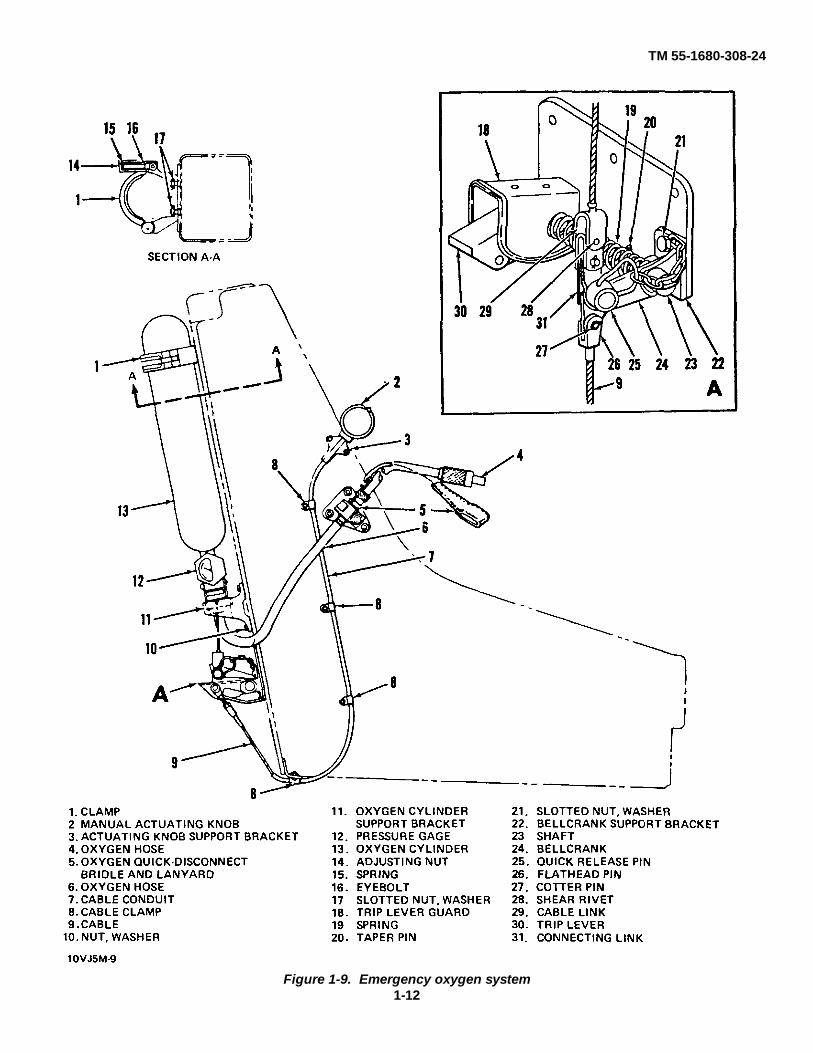
KEY to Figure 1-2.1. Link line2. Drogue line3. Face blind locking
mechanism4. Face blind handle5. Personnel parachute
riser6. Personnel parachute
container7. Backplate with lumbar
support contour8. Occupant retention
assembly9. Rigid seat survival kit
cushion10. Leg restraint quick-release
garter11. Guillotine initiator12. Manual override handle
13. Seat height adjustmentswitch
14. Electrical disconnect15. Emergency oxygen quick-
release pin16. Oxygen quick-disconnect
fitting17. Emergency oxygen manual
control18. Oxygen cylinder19. Tune release mechanism
trip rod20. Time release mechanism21. Parachute restraint strap
(long)22. Parachute restraint strap
(short)23. Guillotine head assembly24. Link line
25. Top latch plunger (withhandwheel installed)
26. Drogue gun27 Drogue gun trip rod28. TCR cable dispenser29. Seat bucket30 Leg restraint roller bracket31. Leg restraint quick-release
pin32. Inertia reel manual control
handle33. Leg restraint cord lockrelease handle34. Leg restraint cords35. Tip-off compensating
rocket motor36. Snubber finger rings37. Lower firing handle38. Thigh supports
Figure 1-2. Ejection seat component location (Sheet 2 of 2)
mechanism (20). So long as the scissor is closed, theshackle and the drogue parachute remain securelyattached to the ejection seat. When the jaws of thescissor open, the pull of the drogue parachute istransmitted, through a link line to the personnelparachute, extracting it from the container (6) fordeployment.
(3) Personnel parachute. A 28-foot inflation aidedpersonnel parachute is housed in a fiberglass container(6) near the top of the ejection seat The personnelparachute provides a safe descent for the occupant atapproximately 18 feet per second.
g. Time Release Mechanism. The time releasemechanism (20, figure 1-2) is mounted on the upper rightside of the ejection seat Its function is to provide a timedelay of approximately 1-3/4 seconds after the ejectionseat has started to rise before allowing the drogue toextract the personnel parachute. A barostat, mounted onthe time release mechanism, prohibits action above apresent altitude of 14, 000 to 15, 000 feet. The timerelease mechanism accomplishes the following actionssimultaneously by, mechanical linkages:
(1) Allows the restraining scissor on the, ejectionseat to open. This releases the drogue parachute from itsattachment to the seat structure enabling it to extract thepersonnel parachute for deployment.
(2) Releases occupant restraint points, freeing theoccupant from the ejection seat for subsequent safeparachute descent.
h. Manual Override System.
(1) A manual override system is provided in casethe automatic system malfunctions. The manual overridesystem can be used in the following conditions
(a) Bailout becomes necessary and ejectiongun fails.
(b) Ejection gun fires, but drogue gun fails.
(c) Ejection gun and drogue gun fire, buttime release mechanism fails.
(d) Ejection gun and drogue gun fire, timerelease mechanism functions, but scissor jaws fail toopen.
(e) The manual override handle is also usedfor crash rescue or emergency egress
(2) When the manual override handle (12) ispulled, the following actions take place:
(a) The guillotine cartridge is fired causingthe guillotine cutter to sever the link line.
(b) The leg restraint cords are released fromthe leg restraint cord locks.
(c) The rigid seat survival kit restraint lugsare released from the seat bucket.
(d) The loop strap lug is released from theharness lock mechanism.
(e) The face blind and lower firing handlesare locked.
Change 3 1-5

TM 55-1680-308-24
Figure 1-3. Main beam assembly component location
1-6

TM 55-1680-308-24
Figure 1-4. Seat actuating jack mechanism
1-7

TM 55-1680-308-24
Figure 1-5. Ejection gun operating sequence
1-8

TM 55-1680-308-24
Figure 1-6. Tip-off compensating rocket (M119)
i. Automatic Emergency Oxygen System. Theemergency oxygen system (figure 1-9) consists of a 22 5cubic inch oxygen cylinder (13), filled with 1, 800 to 2,000 psi of aviator's breathing oxygen, and a manualactuating knob (2) located on the upper right side of theseat bucket. An oxygen hose (6) from the oxygencylinder is routed to the upper right side of the seat bucketand is held in place by an oxygen quick-disconnectbridle and lanyard (5). An additional oxygen hose (4) isrouted from the quick-disconnect clamp to the occupant'sface mask. The emergency oxygen system isautomatically actuated upon ejection. As the ejectionseat rises during ejection, a trip lever (30) is deflecteddownward and transmits the deflection to the bellcrank(24), pulling on the oxygen cylinder cable, fracturing abreakoff nipple within the oxygen cylinder, and releasingthe oxygen supply. Since only a 1/4-inch pull on thecable is required to actuate the oxygen cylinder, and thedeflection is not enough to allow the bellcrank and triplever to clear the striker pin, the 1/16-inch aluminum rivetsecuring the two links is sheared. This permits the triplever and bellcrank to be deflected farther downward,unrestricted by the limitations of the oxygen cylindercable. The emergency oxygen can also be actuatedmanually. The manual actuating knob (2) provides formanual actuation of the oxygen cylinder in case of amalfunction in the normal oxygen system. Pulling themanual actuating knob deflects the bellcrank (24)downward, pulls the oxygen cylinder actuating cable,fracturing a breakoff nipple within the oxygen cylinder,and releasing the emergency oxygen supply.
j. Survival Kit Assembly. The rigid seat survivalkit (RSSK) assembly consists of a rigid fiberglass case
containing a survival kit. The case is opened bysqueezing either of two release grips mounted in thesides. Three different survival kits are designed to fit intothe survival kit case. The particular survival kit in usewill depend on the nature of the mission. The threesurvival kits are cold climate survival kit, hot climatesurvival kit, and overwater survival kit.
k. Ground Safety Lock Assembly. The groundsafety lock assembly (flag) consists of six safety pinsplus one positioning (bucket pin) clip. This assemblyprotects against inadvertent firing of the ejection seat.
WARNING
Never remove the safety pins of the ground safety lockassembly unless preparing the aircraft for a mission orperforming authorized maintenance on components of theejection seat requiring removal of safety pins.
1-7. Theory of Operation
Operation of the ejection seat is divided into fourphases clearing the aircraft, stabilization and decelerationof seat and occupant, deployment of personnelparachute, and separation of occupant from ejection scatfor safe parachute descent. These four phases aredescribed in detail in the following subparagraphs Inaddition, operation of the manual override system isexplained.
a. Clearing the Aircraft. Clearing the aircraftis depicted m figure 1-10. Ejection is initiated when theoccupant pulls either the face blind handle (4, figure 1-2)or the lower firing handle (37). This action withdraws theprimary firing pin sear from the firing mechanism in theejection gun. Withdrawal of the sear allows firing pin tostrike the primary cartridge. The heat and pressure fromthe primary cartridge ignites the lower and upper auxiliarycartridges, electing the seat and occupant. As theejection seat moves upward, five separate events areinitiated.
(1) The drogue gun sear is pulled from thedrogue gun (26, figure 1-2) by the drogue gun trip rod(27) attached to the ejection gun crossbeam.
(2) The time release mechanism sear ispulled from the time release mechanism (20) by the timerelease mechanism trip rod (19) attached to the ejectiongun crossbeam.
1-9

TM 55-1680-308-24
1. SHORT RESTRAINT STRAPS 4. ROLLER YOKES 9. PARACHUTE2. PARACHUTE RIPCORD 5. RISER RELEASE FITTING RISER
"D" RING 6. PARACHUTE RELEASE 10. PERSONNEL3. INERTIA REEL LOOP FITTINGS PARACHUTE
STRAP 7. HARNESS 11. LONG RESTRAINT8. LUMBAR BACK REST STRAPS
Figure 1-7. Harness assembly
1-10

TM 55-1680-308-24
Figure 1-8. Leg restraint mechanism
(3) Dual leg restraint cords (34) tighten,pulling the occupant's legs aft and together against theseat bucket (29) to prevent injury as the ejection seatleaves the flight compartment.
(4) The automatic emergency oxygen systemis activated whether needed or not
(5) The TCR initiator cable, attached to theejection gun crossbeam, is deployed from its dispenseras the seat rises from the aircraft. When the ejection gunis approximately rune inches from full extension, theTCR initiator cable is fully extended. As the ejection seatcontinues to rise, the firing pin sear of the rocket motorinitiator is withdrawn which activates the rocket motor.Thrust from the TCR positions the ejection seat in thecorrect attitude for rapid unrestricted deployment of thedrogue parachute, and increases seat trajectory height.
b. Stabilization and Deceleration of Seat andOccupant. The seat is now clear of the aircraft with theoccupant held securely in place by the loop straps andparachute harness assembly (figure 1-7), the lap belt and
survival kit assembly, and leg restraint cords (2, figure 1-8). The TCR has positioned the ejection seat in theproper attitude for drogue parachute deployment. Thedrogue gun fires, forcibly extracting the drogueparachute. The drogue parachute inflates, stabilizing anddecelerating the seat and occupant.
c. Deployment of Personnel Parachute. if theejection took place above 15,000 feet, the barostat onthe time release mechanism prohibits any further actionuntil seat and occupant are below a pre-set altitude (14,000 to 15,000 feet) if the ejection occurred below the pre-set altitude, the automatic series of events continues.Approximately 1-3/4 seconds after the sear has beenpulled from the time release mechanism (20, figure 1-2),the following events are initiated by mechanical linkageThe scissor, holding the drogue shackle to the ejectionseat, opens, releasing the drogue parachute. The pull ofthe drogue parachute is then transmitted, through the linkline, to the personnel parachute (6), extracting it from itspack for deployment. The long and short parachuterestraint straps (21 and 22), holding the personnelparachute to the ejection seat, have also been released,enabling the personnel parachute to be extracted.
Change 3 1-11
TM 55-1680-308-24
Figure 1-9. Emergency oxygen system1-12

TM 55-1680-308-24
Figure 1-10. Low level ejection sequence
1-13

TM 55-1680-308-24
d. Separation of Occupant From Seal, andDescent. Simultaneously with the release of the drogueshackle, the link line pins are withdrawn from the pinretainers. This releases the face blind, which theoccupant has been holding over his face for protectionduring ejection The leg restraint cords (34, figure 1-2),the retention assembly (8), and the loop straps, arereleased, freeing occupant from ejection seat.Temporary restraint of the occupant in the ejection seat ismaintained by two spring-loaded sticker clips. Thesticker clips prevent collision of occupant with ejectionseat during the separation process. This is accomplishedby providing enough restraint to effect a positiveseparation of occupant from ejection seat in response tothe opening shock of the personnel parachute. Thisopening shock overcomes the spring tension establishedfor the sticker clips thus causing the seat and occupant toseparate. The separation action automaticallydisconnects the emergency oxygen hose from theoccupant at the oxygen quick-disconnect fitting (16).The occupant, suspended in the parachute harnessassembly, executes a normal parachute descent. Theejection seat, having been separated from the occupant,falls free.
e. Operation of Manual Override. A manualoverride system is provided in the event of failure of theautomatic system. The occupant initiates the manualoverride system by squeezing and pulling the manualoverride handle (12, figure 1-2) up and aft. This actionfrees the occupant by releasing the leg restraint cords,seat survival kit retention system, and loop straps. At thesame time the guillotine cartridge is fired actuating theguillotine. The guillotine severs the drogue parachute linkline from the personnel parachute withdrawal line. Nowthe occupant can separate himself from the ejection seatby grasping the lefthand personnel parachute riser, nearthe parachute pack, with his left hand, and thrusting hisleft shoulder forward, with a twisting motion from thewaist. Simultaneously with the thrusting and twistingmotion, the occupant pulls the parachute "D" ring,located at the top left corner of the parachute container,with his right hand.
1-8. Leading Particulars
Leading particulars for the Ejection Seat, ModelMK-J5D, are as follows:
a. Firing Time.
Primary cartridgeWhen either face blind or lower firinghandle is pulled.
Lower auxiliary cartridgeAfter 14 inches of travel of innerand intermediate tubes.
Upper auxiliary cartridgeAfter 31 inches (total) travel ofInner and intermediate tubes.
M119 rocketWhen ejection gun is 9 inchesshort of maximum extension.
b. Thrust.
Ejection gun velocity62 feet per second
M119 rocketApproximately 2, 000 pounds thrust
c. Parachute Dimensions.
Drogue parachute5 feet diameter
Personnel parachute28 feet diameter
d. Time Release Mechanism.
Barostatic functionApproximately 14, 000 feet
Time delay1-3/4 seconds
e. Drogue Gun Mechanism.
Time delay1/2 second
f. Seat Raising Mechanism.
Voltage28 volts dc
Travel4.7 inches
1-14

TM 55-1680-308-24
Section III. TEST EQUIPMENT, SPECIAL TOOLS, AND MATERIALS
1-9 Test Equipment and Special Tools.
Table 1-1 provides a list of test equipment and specialtool used to maintain the MK-J5D Ejection Seat.
1-10. Consumable Materials.
Table 1-2 lists consumable materials required formaintenance of the MK-J5D Ejection Seat.
1-11. Fabrication of Test Equipment, Special Tools,and Support Equipment
Table 1-3 provides tabular data for fabrication of testequipment, special tools, and other support equipment
Table 1-1 Special Tools and Test Equipment
Figure andIndex No. Nomenclature Part No. Function
Alignment tool 105GT1024-59 Align ejection seat duringremoval and installation.
** Barostat adapter assembly 105GT1030-23 Vacuum-test barostat on timerelease mechanism.
* Belt insertion tool 105GT1043 Install harness loop strap lockfitting in inertial reel mechanismloop strap lock.
* Cartridge extractor GR506 Remove primary and auxiliarycartridgesfrom ejection gun.
* Cocking tool MBEU/1 1038 Cocking tool for time releasemechanism
* Cocking tool MBEU/4341 Cock drogue gun firingmechanism.
Cradle, transportation, maintenance 105GT1040 Maintenance preparation,storage, and transporting seat.
Crow foot wrench AN8506-11 Tighten drogue gun barrel tospecified (modified) torque.
Cutter, back spot 134XM15499 Spotface slipper attachment(or) holes.
TDO/742
Ejection gun clamp mounting blocks MBEU/8463 Protect ejection gun whensupported in vise.
* Extractor 105GT1046 Remove cartridge from droguegun barrel.
* Firing pin cocking tool MBEU/1321 Cock ejection gun and guillotinefiring mechanisms.
Change 3 1-15
TM 55-1680-308-24
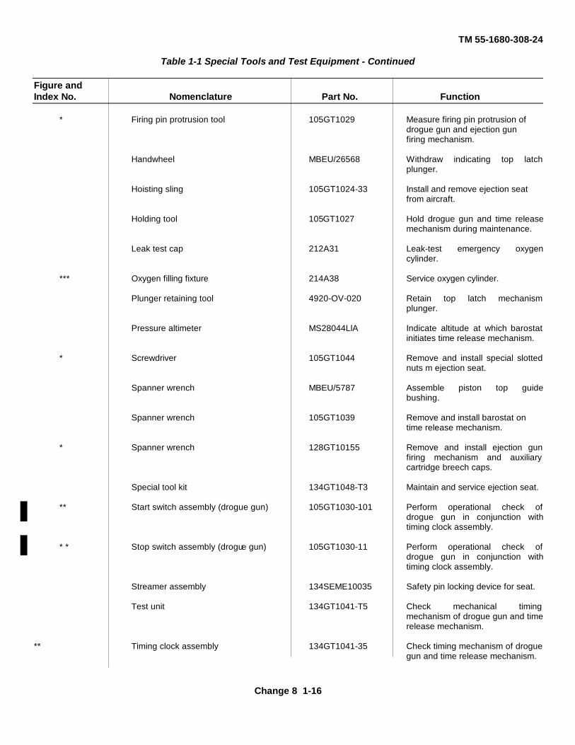
Table 1-1 Special Tools and Test Equipment - Continued
Figure andIndex No. Nomenclature Part No. Function
* Firing pin protrusion tool 105GT1029 Measure firing pin protrusion ofdrogue gun and ejection gunfiring mechanism.
Handwheel MBEU/26568 Withdraw indicating top latchplunger.
Hoisting sling 105GT1024-33 Install and remove ejection seatfrom aircraft.
Holding tool 105GT1027 Hold drogue gun and time releasemechanism during maintenance.
Leak test cap 212A31 Leak-test emergency oxygencylinder.
*** Oxygen filling fixture 214A38 Service oxygen cylinder.
Plunger retaining tool 4920-OV-020 Retain top latch mechanismplunger.
Pressure altimeter MS28044LlA Indicate altitude at which barostatinitiates time release mechanism.
* Screwdriver 105GT1044 Remove and install special slottednuts m ejection seat.
Spanner wrench MBEU/5787 Assemble piston top guidebushing.
Spanner wrench 105GT1039 Remove and install barostat ontime release mechanism.
* Spanner wrench 128GT10155 Remove and install ejection gunfiring mechanism and auxiliarycartridge breech caps.
Special tool kit 134GT1048-T3 Maintain and service ejection seat.
** Start switch assembly (drogue gun) 105GT1030-101 Perform operational check ofdrogue gun in conjunction withtiming clock assembly.
* * Stop switch assembly (drogue gun) 105GT1030-11 Perform operational check ofdrogue gun in conjunction withtiming clock assembly.
Streamer assembly 134SEME10035 Safety pin locking device for seat.
Test unit 134GT1041-T5 Check mechanical timingmechanism of drogue gun and timerelease mechanism.
** Timing clock assembly 134GT1041-35 Check timing mechanism of droguegun and time release mechanism.
Change 8 1-16

TM 55-1680-308-24
Table 1-1 Special Tools and Test Equipment - Continued
Figure andIndex No. Nomenclature Part No. Function
Switch assembly 105GT1030-21 Check time release mechanism running time
Safety lock pin 134SEME10053 Guillotine sear groundmaintenance
Safety lock pin 1345EME10054 TCR rocket Initiator groundmaintenance.
Firing pin protrusion gage J9126 Measure firing pin protrusion ofguillotine firing mechanism
Vacuum pump 4310-900-8136 Operationally check barostat ontime release mechanism.
Vacuum Test Box TDO 1153 Operationally check and adjustbarostat on time releasemechanism.
* Wrench WS1516 Remove drogue gun barrel fromdrogue gun.
* Wrench 105GT1036 Remove and install harnessstrap retraction reel nut
* Wrench 105GT1037 Remove and install leg restraintlever retaining nuts.
*Included in Special Tool Kit, Part No. 134GT1048-T3**Included in Test Unit, Part No. 134GT1041-T6***Used on 51C3804 Filler Valve only
Table 1-2 Consumable Materials
MilitaryItem No. Nomenclature Specification Used For
1 Lockwire MS20995C20 Safety wiring2 Lubricating oil, general purpose MIL-L-7870 General lubrication34 Tetrachloroethylene, technical O-T-236 Cleaning5 Grease, aircraft and instrument MIL-G-23827 Lubrication6 Drycleaning solvent P-D-680 Cleaning7 Oxygen, aviators', breathing, MIL-0-27210 Oxygen servicing
grade 18 Grease, molybdenum disulfide MIL-G-21164 Lubrication
Change 5 1-17

TM 55-1680-308-24Table 1-2. Consumable Materials-Continued
MilitaryItem No. Nomenclature Specification Used For
10 Lubricant, solid, film MIL-L-23398 Lubrication
11 Nylon thread (No 6 ticket) FED V-T-295 Safe tie
12 Lubricating oil MIL-L-83767 Vacuum pump
13 Leak test compound MIL-L-265567 Leak-testing oxygen system
14 Locktight MIL-S-22473 Dowel screw, safety
Table 1-3. Test Equipment, Special Tools and Support Equipment Fabrication Data
Figure andIndex No. Nomenclature Function
1-11 Top latch plunger retaining tool Retain top latch plunger during disassembly
1-12 Cartridge block Store and ship spare cartridges.
Figure 1-11. Top latch plunger retaining tool
Change 2 1-18

TM 55-1680-308-24
Figure 1-12. Cartridge block
Change 2 1-19

TM 55-1680-308-24
1-12. In-Service Cartridge Storage.
Ejection seat cartridges may be stored in adesignated area of the hangar or maintenance areaapproved by the local safety officer. The designated areamust be free of battery charging fuses, large electricmotors, flammables and/or open flame. The followingprovisions shall also apply:
a. A maximum of six ejection seats worth ofcartridges may be stored at any one time.
b. Ejection seat cartridge sets shall be packagedin the cartridge block depicted in figure 1-12. A 50 caliberammunition container similarly configured may also beused.
c. A metal container constructed of 1/8 inch thickmild steel sheet, with welded joints, hinged lid and haspfor locking is an approved storage container. Six each1/4 inch vent holes shall be drilled through each end tofacilitate ventilation.
d. The container should measure 29 inches long,18 inches wide and 10 inches deep. These minimummeasurements will accommodate the cartridge blocks andone rocket motor shipping container.
e. The storage container shall be painted insigniared (MIL-E-7729) with the words "CAUTIONEXPLOSIVES CONTAINED INSIDE" painted in whiteinsignia enamel (MIL-E-7729). It shall be secured to thefloor in an area free of traffic.
f. A key lock with two sets of keys, one retainedby the ejection seat lead man (NCOIC) and the other bythe Maintenance Officer, shall be utilized for controlledaccess to the explosives.
NOTE
M119 rocket motors are not normally re-moved from the ejection seat except forreplacement actions. Therefore, not morethan two motors packed in original crate,shall be stored in this locker duringunscheduled maintenance periods.
Change 2 1-20

TM 55-1680-308-24
CHAPTER 2
GENERAL SYSTEM DESCRIPTION2-1. General.
This chapter provides a description of the operatingcontrols, their use, and location. Both normal andemergency operating procedures are described Data isprovided describing the use of the emergency oxygensupply and the use of components of the survival kit.
2-2. Operating Controls.
Table 2-1 provides a list of operating controls andtheir functions Figure 2-1 depicts the locations of theoperating controls.
2-3. Normal Operating Procedures.
Normal operating procedures for the ejection seatcan be divided into two categories ejection procedures,and procedures not involving ejection.
a. Normal Ejection Procedures. Either one of twopull handles, the face blind (or upper firing handle) (1,
figure 2-1), or the lower firing handle (4) when pulled, willbegin a normal ejection and automatic separation fromthe ejection seat. Pulling down on the face blind handlewith both hands will provide a face cover and, at thesame time, fire the ejection gun. The lower firminghandle is used for ejection in event the face blind handleis inaccessible because of abnormal flight conditions orfor any other reason.
b. Normal Procedures Not Involving Ejection.
(1) Inertia reel manual control handle. Theinertia reel manual control handle (5, figure 2-1) is athree-position lever which is connected to andcontrols the operation of the inertia reelmechanism The mechanism consists of a spring-loaded strap retention reel, loop straps, snubbers,and a harness lock. When the three-position handleis m the forward or locked position, forwardmovement is prevented by snubbers, and any slackis taken up by the reel, keeping the harness loopstrap taut When the handle is cycled through the aftposition, the snubbers unlock and the handle is
Table 2-1. Operating Controls
Figure 2-1Index No. Nomenclature Function
1 Face blind handle Initiate ejection sequence
2 D-Ring Release personnel parachute for deployment.
3 Survival kit grips Open survival kit rigid container
4 Lower firing handle Initiate ejection sequence.
5 Inertia reel manual control handle Release or locks inertia reel system loopstrap
6 Leg restraint cord lock release handle Release leg restraint cords
7 Manual override handle Emergency release from ejection system.
8 Seat height adjustment switch Raise and lowers seat bucket
9 Emergency oxygen manual control knob Manually actuate the oxygen cylinder
2-1

TM 55-1680-308-24
Figure 2-1. Operating controls
2-2

TM 55-1680-308-24
spring-loaded to the auto lock position. In the auto lockposition, the loop straps may be extended, allowing theoccupant to move forward and will lock when subjected to2 to 3 g.
(2) Leg restraint cord lock release handle (6,figure 2-1). The leg restraint cord lock release handle is atwo-position lever, spring-loaded to the aft position.Placing the handle m the forward position releases theupper end of the leg restraint cords.
(3) Leg restraint cord snubber finger rings (7,figure 1-8). The leg restraint cord snubber finger rings,when pulled, allow the occupant to pull the leg restraintcords forward to provide sufficient comfortable legmovement.
(4) Seat height adjustment switch (8, figure2-1).
Do not operate the seat raising actuator morethan 1 minute (maximum) during any 8-minuteperiod of time. Extended operation will shortenthe seat raising actuator service life.
When the seat height adjustment switch is pushedforward, it lowers the election seat by activating the seatactuating jack mechanism. When the seat heightadjustment switch is pulled aft, the ejection seat is raised.The switch is spring-loaded and will return to the center(neutral) position when released. The total vertical travelcapability of the MK-J5D Ejection Seat is 4 7 inches Awhite EYE LEVEL line is painted on the side of theejection seat to guide the occupant while correcting seatheight adjustment.
2-4. Emergency Operating Procedure.
If the automatic ejection system of the MK-J5DEjection Seat fails, there are provisions for bypassing theautomatic functions These provisions involve the use oftwo controls, the manual override handle (7, figure 2-1),and the D-ring (2).
a. Manual Override Handle (7, Figure 2-1). Themanual override handle is used to bypass the automaticejection functions of the drogue gun, the drogueparachute, or the time release mechanism. To use themanual override handle, the trigger and handgrip mustbe squeezed and the handle pulled up and aft. Thisresults in the following actions.
(1) The face blind handle and the lower firinghandle are locked in position to prevent accidental firingof the ejection gun if it had not been fired.
(2) The leg restraint cords and seat retentionsystem are released, freeing occupant from ejection seat.
(3) A cartridge is fired, causing the guillotineto sever the drogue parachute from the personnelparachute.
b. D-Ring (2, Figure 2-1). After the occupant isfree of the ejection seat, he pulls the D-ring whichdeploys the personnel parachute.
2-5. Use of Oxygen Supply and Survival Kit
Operation of the oxygen supply system and thesurvival kit involves use of the emergency oxygen manualcontrol (9, figure 2-1) and the survival kit grips (3).
a. Emergency Oxygen Manual Control. Theemergency oxygen manual control provides for manualactuation of the emergency oxygen system in case ofmalfunction in the aircraft (normal) oxygen system.When the emergency control (ball) is pulled outward, itpulls the oxygen cylinder actuating cable, fractures abreakoff nipple within the oxygen cylinder, and releasesthe oxygen.
b. Rigid Seat Survival Kit A successful ejectionends with the occupant performing a normal parachutedescent supported by his 28-foot personnel parachuteAttached to the parachute harness and providing a seatfor the occupant during his parachute descent, is afiberglass case containing a survival kit To open thefiberglass case and release the survival kit, occupantmust squeeze and pull either survival kit grip (3, figure 2-1) For contents of survival kit container, refer to TM 55-8645-206-23.
2-3/(2-4 blank)

TM 55-1680-308-24
CHAPTER 3
ORGANIZATIONAL MAINTENANCE INSTRUCTIONS
Section I. PREPARATION FOR MAINTENANCE, STORAGE, AND RESHIPMENT.
(Not applicable)
Section II. INSTALLATION.
(Not applicable)
Section III. INSPECTION AND SERVICING.
3-1. General.
The following paragraphs provide inspection,servicing and maintenance procedures authorized fororganizational maintenance by the MaintenanceAllocation Chart for the MK-J5D Ejection Seat.
3-2. Inspection Requirements.
The types of inspection to be performed are asfollows:
a Daily Inspection. Perform daily inspection toverify serviceability of the ejection seat in accordancewith PMD.
b Intermediate Inspection. Accomplishscheduled intermediate inspection of the ejection seat inaccordance with TM 55-1510-217-PM.
c. Periodic Inspection. The scheduled periodicinspection of the ejection seat shall be accomplished inaccordance with TM 55-1510-217-PM.
d Special Inspections The special inspectionslisted as follows shall be performed in accordance withthe applicable specified time interval and in accordancewith the procedures contained in this technical manual.
e. Thirty day inspection. The thirty day inspectionwill be performed by organizational maintenance asoutlined in paragraph 3-3.
(2) One-hundred eighty day Inspection Theone- hundred eighty day inspection shall be accomplishedat direct support or general support maintenance level.(Refer to paragraph 4-6 ).
WARNING
Personnel parachute pack utilizing plasticsuspension time stowage tray shall requireejection seat to be inspected at 90 day interval.
(3) One year requirements The one yearrequirements shall be accomplished at direct support orgeneral support maintenance level (Refer to paragraph 4-7 ).
(4) Three year requirements. The three yearrequirements shall be accomplished at direct support orgeneral support maintenance level (Refer to paragraph 4-8).
(5) Deleted.
(6) Five year requirements. The five yearrequirements shall be accomplished at direct support orgeneral support maintenance level (Refer to paragraph 4-10).
(7) Six year requirements The six yearrequirements shall be accomplished at direct support orgeneral support maintenance level (Refer to paragraph 4-11).
Change 10 3-1

TM 55-1680-308-24
(8) Seven year requirements The sevenyear requirements shall be accomplished at AVIMmaintenance level (Refer to paragraph 4-12).
(9) Eleven year requirements The elevenyear requirements shall be accomplished at AVIMmaintenance level (Refer to paragraph 4-13).
(10) Fifteen year requirements The fifteenyear requirements shall be accomplished at AVIMmaintenance level (Refer to Paragraph 4-14).
(11) Deleted.
3-3. Thirty Day Inspection.
This inspection shall be performed by qualifiedpersonnel as outlined in table 3-1.
NOTE
Upon completion of the following inspection, thedate, inspector's name, and unit will be enteredon DA Form 3912 located on the right- hand sideof the personnel parachute pack and the flap ontop of the drogue pack.
Table 3-1. Thirty Day Inspection Requirements
Item Major Assembly, Item, or Area Requirement
Lines Drogue line and link line Inspect for condition and security of installation.
Safety tie Drogue shackle safety tie and drogue Inspect for security of installation and properflap securing pin safety tie attachment
Restraint Personnel parachute pack Unbuckle personnel parachute restraint strapon each side of head box.
Locking pins and cones Personnel parachute pack First remove parachute withdrawal line fromguillotine and then pull top of personnelparachute forward approximately 3 inches.Open top outer and inner flaps exposinglocking pins and cones Check for properengagement, corrosion and damage tolocking pins and condition of parachutewithdrawal line
Safety tie Personnel parachute pack Ensure that safety tie is intact
Flaps and covers Personnel parachute pack Check condition of covers and secure topinner and outer flaps
Restraint straps Personnel parachute pack Move parachute aft on support, flush withseat back. Inspect parachute restraint strapsfor condition and security. If restraint strapsare free of defects, reinstall strap on each sideof head box. Install parachute withdrawal lineinto guillotine with the excess line positionedto the rear of the guillotine.
Change 10 3-2

TM 55-1680-308-24Table 3-1. Thirty Day Inspection Requirements (Cont)
Item Major Assembly, Item, or Area Requirement
Risers Personnel parachute Inspect personnel parachute risers for cuts,frayed stitching, and discoloration from exposure to sunlight.
D-ring Personnel parachute Check parachute ripcord handle (D-ring)for retention to clip on left side ofparachute pack.
Release fittings Personnel parachute Check riser release fittings for ease ofoperation and positive locking There shallbe no binding or hangup during openingand closing.
NOTE
If any doubt of the serviceabilityof the items listed in this tableexists, a qualified parachuterigger should be consulted.
Change 5 3-2.A/(3-2.B blank)

TM 55-1680-30824
3-4. Servicing.
The application of recommended lubricants to theirrelevant bearing surfaces, together with the observanceof absolute cleanliness, will ensure the maximumefficiency and utmost service of the ejection seat andthe components thereof
a. Lubrication Frequencies. Lubricationfrequencies are limited to the intervals specified herein,except where conditions warrant their change
b. Lubrication Precautions and Procedures.Lubrication precautions and procedures outlined in thistechnical manual will be strictly complied with at alltunes No alternate lubricant shall be applied to theejection seat unless specifically outlined herein.
c. Lubrication Requirements. Each part of theejection seat or any component thereof, as depicted infigure 3-5, is indicated by a frequency symbol which showsthe time interval between lubrications. Application symbolswithin the frequency symbol show how the lubricant isapplied A parts nomenclature key, referred to by a numberadjacent to the frequency symbol, identifies the part to belubricated A code of either one, two, or three letters withinthe frequency symbol identifies the type of lubricant. Partsor areas to be lubricated on both sides of the ejection seatare indicated by broken leader lines. If a part Is to belubricated in more than one place, the number of places isindicated In parentheses along the leader line All symbolsand codes are explained in figure 3-5
Section IV. PREVENTIVE MAINTENANCE
3-5. Introduction.
Periodic performance of the preventive maintenancedetailed herein will ensure maximum efficiency andreliability of the MK-J5D Ejection Seat and itscomponents
3-6. Cleaning.
Cleaning of the ejection seat and the ejection seatcomponents by organization maintenance is to beaccomplished as such conditions warrant Only thecomponents outlined in following subparagraphs athrough d should be cleaned, using the prescribedmaterials and procedures. Never attempt to performcleaning on any unauthorized area or component.
WARNING
Before attempting to service the ejection seat orejection seat components with ejection seatinstalled In the aircraft, ensure that groundsafety locks are installed.
a. Harness Assembly.
(1) Clean harness assembly using a solution ofwarm water and a synthetic detergent (hand-dishwashing compound). Dissolve one to four ounces ofdetergent m one gallon of water and scrub harness
lightly with a soft-bristled brush.
(2) Rinse harness assembly by applying clearwater, as sparingly as possible, to remove detergentsolution.
(3) Allow harness assembly to dry thoroughly
WARNING
Do not dry harness assembly in direct sunlight, assunlight causes harness deterioration which mayresult In separation of occupant from personnelparachute after ejection.
b. Loop Strap.
(1) Position inertia reel manual control handle tounlock (aft) position and pull loop strap out to the fullyextended position and hold loop strap.
(2) Spot-clean soiled areas with a soft-bristledbrush or clean cloth dampened with tetrachloroethylene(item 4, table 1-2).
(3) Rinse spot-cleaned area withtetrachloroethylene (item 4, table 1-2).
3-3

TM 55-1680-308-24
c. Seat Cushion, Back Rest Cushion and FloatingLap Belt.
(1) Clean soiled seat cushions and lap beltswith a solution of warm water and a synthetic detergent(hand-dishwashing compound). Dissolve one to fourounces of detergent In one gallon of water and scrubcushions lightly, using a soft-bristled brush or a cleancloth.
(2) Remove detergent solution with a cleancloth dampened in clear water
NOTE
Seat and back rest cushions may be lifted outfor improved accessibility.
d. Leg Restraint Cords and Quick-Release Garters.
(1) Hold snubber finger rings out and pull legrestraint cord out as far as possible Remove quick-releasegarters from leg restraint cords
(2) Clean leg restraint cords quick-release gartersin same manner as prescribed for harness assembly (Referto preceding subparagraph a )
(3) Install quick-release garters on leg restraintcords
3-7. Lubrication.
For lubrication instructions, refer to paragraph 34.
3-8. Extreme Environmental Maintenance.
No special instructions or special maintenance is requiredfor extreme environmental conditions.
Section V. OPERATIONAL CHECKOUT
3-9. General.
Operational requirements and procedures for verifyingserviceability of the operating controls and linkages, asapplicable to organizational maintenance, shall beperformed on the ejection seat and components asconditions warrant These components include the faceblind locking mechanism, dual leg restraint mechanism,inertia reel manual control, and the seat actuating jackmechanism.
310. Operational Checks
The following operational checks are authorized fororganizational maintenance
a. Face Blind Locking Mechanism.
(1) Remove safety pin of ground safety lockfrom face blind locking mechanism (3, figure 1-2).
(2) With the safety lock of face blind lockingmechanism m up (locked) position, the locking plungermust engage the face blind handle body (visual).
(3) With the safety lock of the face blind lockingmechanism in the down (unlocked) position, the lockingplunger must be clear of the face blind handle body(visual).
WARNING
Do not pull face blind.
(4) Install safety pin of ground safety lock In theface blind locking mechanism.
b. Leg Restraint Mechanism.
(1) Ensure leg restraint cord lock release handle(33, figure 1-2) Is m forward (locked) position.
(2) Pull on lower end (under seat bucket) of legrestraint cord (2, figure 1-8) and ensure it passes throughsnubber freely
(3) Pull forward on leg restraint cord and ensurethat line Is held by snubber.
(4) Pull forward on leg restraint cord and pull onsnubber finger ring (7). Ensure leg restraint cord will pullout freely while snubber finger ring is held out
NOTE
The snubber finger ring is spring-loaded and willreturn to the locked position when released.
3-4

TM 55-1680-308-24
(5) Insert cord lock fitting (6) on upper end ofleg restraint cord (2) into leg restraint cord lock (5) infront of seat bucket. Ensure cord lock fitting is secure.
(6) Move leg restraint cord lock release handle(33, figure 1-2) to its aft (unlocked) position and ensurethat upper end of leg restraint cord (2, figure 1-8) isreleased Leg restraint cord lock release handle shouldmove freely without binding.
(7) Ensure leg restraint cord lock releasehandle (33, figure 1-2) returns to its forward (locked)position.
(8) Perform preceding steps (1) through (7) onopposite leg restraint cord (2, figure 1-8) and cord lockfitting (6).
c. Inertia Reel Manual Control.
(1) Place inertia reel manual control handle (32,figure 1-2) in center (autolock) position
(2) Pull loop strap out to extreme position
(3) Move inertia reel manual control handle toforward (locked) position.
(4) Slowly allow loop strap to retract a fewinches at a time; then pull forward on loop strap to see ifloop strap locks.
(5) Repeat procedure m preceding step (4)until loop strap is fully retracted.
(6) Move inertia reel manual control handle tocenter (autolock) position and pull on loop strap. Loopstrap should be locked.
(7) Move inertia reel manual control handle toaft (unlocked) position and release handle. Handleshould move to center (autolock) position.
NOTE
The inertia reel manual control handle is spring-loaded to the center (autolock) position.
(8) Pull loop strap out to the fully extendedposition and slowly release loop strap Loop strap should
completely retract.
d. Seat Actuating Jack Mechanism.
(1) Ensure all switches are off.(2) Connect external power to aircraft in
accordance with TM 55-1510-204-23 or TM 55-1510-213-23.
(3) Check that ejection seat moves up when seatheight adjustment switch (2, figure 3-6) is pushed aft, andstops when switch is released.
CAUTION
Do not operate the seat raising actuator more than Iminute (maximum) during any 8-minute period oftime Extended operation will shorten the seatraising actuator service life.
(4) Check that ejection seat moves down whenseat height adjustment switch is pushed forward, and stopswhen switch is released.
(5) Check that ejection seat actuating jack stopswhen full down position Is reached.
(6) Remove external power from aircraft maccordance with TM 55-1510-204-23 or TM 55-1510-213-23.
3-11. Troubleshooting Data.
Troubleshooting is the systematic isolation ofdefective or inoperative components or systems by meansof analysis of trouble symptoms, checking to determine thecomponent(s) or system at fault, and the application of thecorrective action. Troubles which may be encounteredduring operation or checkout of the ejection seat are listedin table 3-2. Probable causes and corrective actions arelisted opposite each medication of trouble Careful study ofthis table will give a general knowledge of difficulties whichmay be encountered at organizational maintenance level, aquick, easy method to analyze the probable cause, and thecorrective action to be taken Before condemning acomponent or system, a thorough check should be made todetermine if failure is due to another component or systemoperating in conjunction with the component or systemassumed to be faulty.
Change 4 3-5

TM 55-1680-308-24
Table 3-2. Troubleshooting, Organizational Maintenance
Malfunction Probable Cause Corrective Action
1. Seat height adjustmentswitch
a. Monitored dc bus not energized. a. Apply external power. (Referto inoperative. TM 55-1510-204-23 or TM55-1510-213-23)
b. Low or no power supply. b. Check for proper source ofsupply (minimum 20 amperes).
c. Foreign object blocking normalmovement of seat.
c. Remove foreign object
d. Electrical lead to seat height adjustmentmechanism defective
d Notify Direct Supportmaintenance.
2. Leg restraint cords do not a. Leg restraint cords twisted. a Straighten leg restraint cords.lock when pulled in restrain-mg position.
b. Snubber mechanism jammed ordefective.
b. Notify Direct Supportmaintenance.
3. Leg restraint cords will notunlock when leg restraint
a. Locking mechanism jammed in lockedposition
a. Notify Direct Supportmaintenance
cord lock release handle ispositioned to aft (unlocked)position.
b. Snubber jammed in locked position. b. Notify Direct Supportmaintenance.
4. Harness loop strap will notlock.
a. Dirt or obstruction in snubber mechanism. a Notify Direct Supportmaintenance
b. Maladjusted linkage b Notify Direct Supportmaintenance.
312. Adjustment and Alignment
Adjustment and alignment procedures are notapplicable to organizational level of maintenance.
3-6 Change 4

TM 55-1680-308-24
Section VI. REPAIR AND REPLACEMENT OF AUTHORIZED PARTS
3-13. Introduction.
Prescribed Inspections detailed herein will ensuremaximum efficiency of the MK-J5D Ejection Seat.
314. Ground Safety Lock.
Ground safety lock inspection. The ground safetylock (figure 3-1) consists of safety pins and onepositioning (bucket pin) clip. The safety pins provideprotection against the inadvertent firing of any chargesin the ejection seat.
WARNING
Never remove the safety pins of the groundsafety lock assembly unless preparing theaircraft for a mission or performing authorizedmaintenance on components of the ejectionseat requiring removal of safety pins.
a. Removal. Remove quick-release type safetypins and bucket pin from ejection seat as follows:
(1) Lower firing handle (Detail E)
(2) Manual override handle (Detail F)
(3) Bucket pin (Detail G)
(4) TCR cable dispenser (Detail D)
(5) Drogue gun (Detail C)
(6) Face bind locking mechanism (Detail B)
(7) Ejection gun firing pin sear (Detail A)
b. Inspection.
(1) Inspect quick-release type safety pins forsecurity of attachment to ground safety lock (flag).
(2) Inspect safety pins for corrosion and forease of operation.
c. Installation.
(1) Remove ground safety lock from storagearea in aircraft.
(2) Install quick-release type safety pins and
bucket seat pin at locations shown in figure 3-1 in reverseorder of removal.
3-15. Face Blind Locking Mechanism.
Face blind locking mechanism Inspection. The face behindlocking mechanism (3, figure 1-2) is located on top of theheadbox. It prevents accidental extraction of the face blindby locking the face blind handle (4) in its proper, position.The face blind locking mechanism is in the unlockedposition when the safety lock is down and is in the lockedposition when the safety lock is up.
a. Ensure safety lock will lock and unlock easilywithout binding
b. Ensure safety pin lock is not malformed and willaccept the safety pin of ground safety lock when in lockedposition.
3-16. Top Latch Mechanism and Trip Rods.
Top latch mechanism and trip rod Inspection. The top latchmechanism locks the seat structure to the ejection gun sothat the ejection seat is held firmly in the aircraft untilejection occurs. The top latch mechanism Is installed mthe top of the left vertical main beam. Inspect the top latchmechanism as follows:
a. Ensure indicating dowel pin is flush with plungerface (See figure 3-2 ).
b. Ensure plunger face is flush with edge of plungerhousing.
c. Visually check to ensure drogue gun/TCR initiatorcable assembly and time release mechanism trip rod(figure 3-3) indicating collars are flush with, or not morethan 1/2-inch maximum away from, edge of trip rod outerbarrel when connected to crossbeam
d. If the top latch mechanism and indicating trip rodcollars do not meet the above requirements. Indicating animproperly installed ejection seat, notify Direct Supportlevel of maintenance.
3-17. Harness and Lap Belt
Harness assembly and floating lap belt inspection. Theharness assembly (figure 1-7) and the floating lap beltprovide a means of attaching the occupant to the ejectionseat.
3-7

TM 55-1680-308-24
Figure 3-1. Ground safety lock location view
3-8

TM 55-1680-308-24
Figure 3-2. Inspection of top latch mechanism
3-9

TM 55-1680-308-24
Figure 3-3. Trip rod Indicating collar installation
Quick-release type fittings are provided forattachment to adapters located on the parachute risersand the rigid seat survival kit (RSSK).
a. Inspection.
(1) Inspect harness and floating lap belt forcleanliness, fraying, discoloration and loose stitching.
(2) Inspect metal fittings and quick-releaseadapters for corrosion and damage.
NOTE
If any doubt of the serviceability of this systemexists, a qualified parachute rigger should beconsulted or the personnel harness assemblyshould be forwarded to a parachutemaintenance shop for rework.
b. Installation.
(1) Attach harness to the parachute riseradapters and the floating lap belt to the RSSK retentionadapter fittings.
(2) Check for quick-release action duringinstallation of the adapters to the fittings for smoothness ofoperation.
c. Removal.
(1) Check quick-release action of fittings duringremoval.
(2) Remove harness and lap belt from seat andstore in appropriate area if assembly meets the installationand removal check requirements. If repair is required,dispatch harness or belt to parachute riggers or replace witha serviceable harness assembly or floating lap belt.
3-18. Sticker Clips.
Sticker clips inspection. A sticker clip Is located on each ofthe outer sides of the seat bucket. These clips provide areceptacle for the sticker strap lugs (figure 3-4). The stickerclips restrain the occupant in the ejection seat until thepersonnel parachute is deployed.
a. Inspect sticker clips on both sides of seat bucket forsecurity of installation.
b. Ensure that each sticker strap lug is securelyinserted into its respective sticker clip.
c. If defects are found, inform Direct or GeneralSupport level of maintenance.
3-19. Leg Restraint System
a. Leg restraint cords and quick-release garters. Theleg restraint cords (2, figure 1-8), attached to the quick-release garters (1), pull the occupant's legs against theejection seat thigh supports during ejection by the initialmovement of the seat.
(1) Cleaning. Clean the leg restraint cords andquick-release garters in accordance with paragraph 3-6d
(2) Inspection.
(a) Inspect leg restraint cords for fraying, loosestitching, and for cleanliness.
(b) Inspect quick-release garters for fraying,loose stitching, and cleanliness.
(c) Inspect hardware of leg restraint cords andquick-release garters for corrosion and for ease ofoperation.
3-10

TM 55-1680-308-24
30VJ5M-4
Figure 3-4. Seat pan component location
3-11

TM 561680-30824
(d) Replace leg garters if found defectiveduring inspection.
(e) Inform Direct or General Support levelof maintenance if leg restraint cords are found defectiveduring inspection.
b. Dual leg restraint cord lock and snubber unit.The dual leg restraint cord lock and snubber unitsecures the lock fitting of the leg restraint cord (2, figure1-8) to the ejection seat.
(1) Servicing. Service the dual leg restraintcord lock and snubber unit in accordance with figure 3-5.
(2) Inspection.
(a) Refer to paragraph 3-10b for operationalprocedures to check out the dual leg restraint cord andsnubber unit
(b) If defects are found during inspection,inform Direct or General Support level of maintenance.
3-20. Seat Actuating Jack Mechanism.
Seat actuating jack mechanism inspection. The seatactuating jack is located in back of the seat bucket,between the main beams The shaft end of the actuatingjack is bolted to the 40 g crossmember, and the motorend is attached to the seat bucket. The seat actuatingjack motor operates off the aircraft 28-volt dc systemand Ls actuated by a seat height adjustment switch (2,figure 3-6) located on the forward right side of the seatbucket. The seat height adjustment switch has threepositions up (switch aft), down (switch forward), andneutral. The height of the seat bucket may be adjustedthrough a distance of 4.7 inches.
a. Inspection of the seat actuating jack mechanismconsists of the proper operation of the switch and seattravel. Refer to paragraph 3-10d for operationalprocedures.
b. If defects are found during inspection, informDirect or General Support level of maintenance.
3-21. Emergency Oxygen System.
Emergency oxygen system inspection. Theemergency oxygen system consists of a 22.5 cubic inchoxygen cylinder (13, figure 1-9) filled with 1,800 to 2,000psi of breathing oxygen, and a manual actuating knob(2) located on the upper right side of the seat bucket.An oxygen hose (6) from the oxygen cylinder is routedto the upper right side of the seat bucket and is held Inplace by an oxygen quick-disconnect bridle and lanyard
(5) An additional oxygen hose (4) is routed from the quick-disconnect clamp to the occupant's face mask. Theemergency oxygen system is automatically actuated uponejection. As the ejection seat rises during ejection, a triplever (30) is deflected downward and transmits thedeflection to the bellcrank (24), pulling on the oxygencylinder cable, fracturing a breakoff nipple within theoxygen cylinder, and releasing the oxygen supply. Sinceonly a 1/4-inch pull on the cable is required to actuate theoxygen cylinder, and the deflection is not enough to allowthe bellcrank and trip lever to clear the striker pin, the 1/16-inch aluminum rivet securing the two links is sheared. Thispermits the trip lever and bellcrank to be deflected furtherdownward, unrestricted by the limitations of the oxygencylinder cable.
a. Inspect oxygen hose for cracks and deterioration.
b. Inspect oxygen hose fittings for serviceability.
c. Inspect oxygen quick disconnect bridle and lanyardfor fraying, loose stitching, and for proper installation.
d. Inspect oxygen cylinder for security of mounting.
e. Visually check oxygen cylinder quantity indicatorfor proper capacity.
f. Ensure quick-release pin is installed.
g. Inspect green knob for security.
h. If defects are found during inspection, refer toDirect Support or General Support level of maintenance.
3-22. Personnel Parachute Container and RestraintStraps.
Personnel parachute container and restraint strapinspection. The personnel parachute container (6, figure 1-2), which packs a 28-foot diameter inflation aidedparachute, is held in position on the ejection seat by a longrestraint strap (21) and a short restraint strap (22).
a. Inspect for cleanliness
b. Inspect personnel parachute container covering forloose stitching, wear, deterioration, and security of cover tovelcro fasteners.
c. Ensure ripcord D-ring is fully inserted in its properposition and secured by retainer clip.
d. Inspect personnel parachute (fiberglass) containerfor fractures.
3-12

TM 55-1680-308-24
Figure 3-5. Lubrication chart3-13
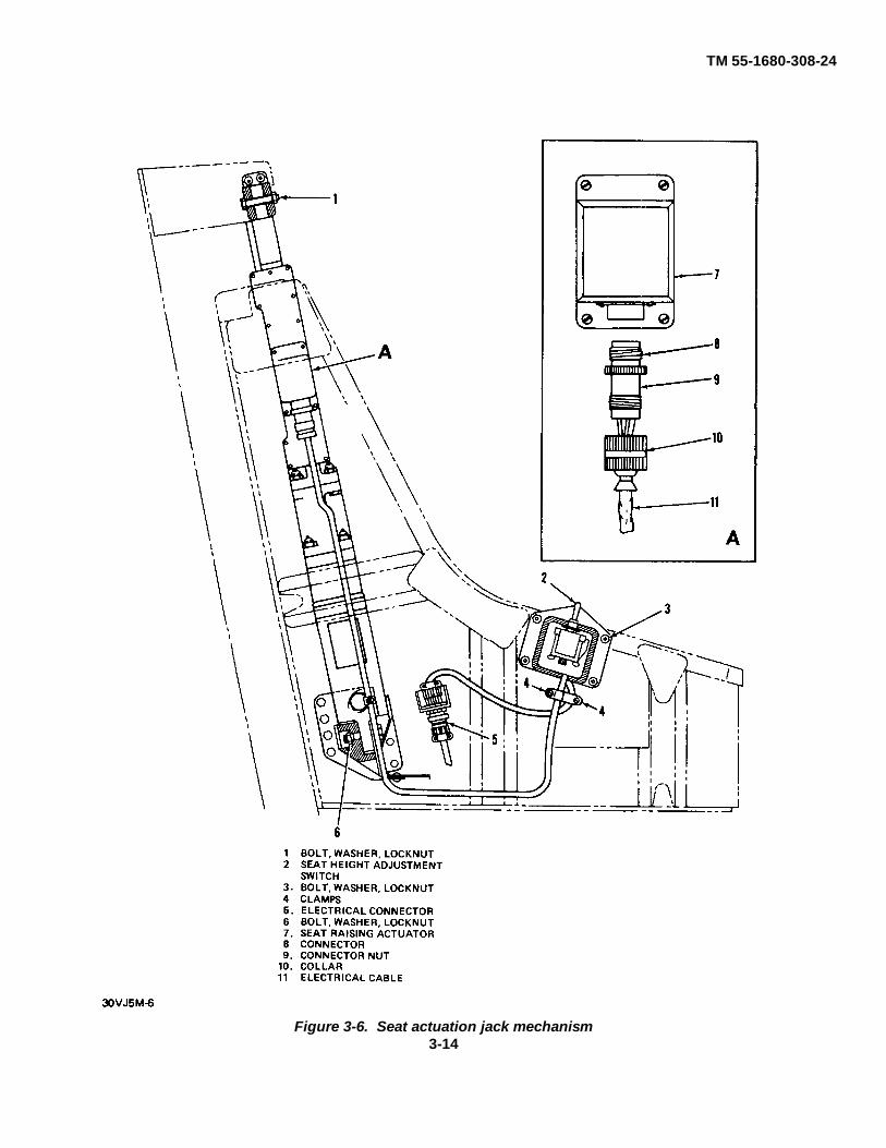
TM 55-1680-308-24
Figure 3-6. Seat actuation jack mechanism3-14

TM 55-1680-308-24
e. Inspect personnel parachute restraint straps forloose stitching, fraying, and cleanliness.
f. Inspect to ensure that long and short restraintstraps properly secure the container to the seat.
g. If discrepancies are found during Inspection,inform parachute riggers or Direct or General Supportlevel of maintenance.
3-23. RSSK, Seat Pan, and Cushion.
RSSK, seat pan, and cushion Inspection. The seat pan(figure 34) provides proper support for the lower portionof the torso and is covered with a seat cushion Attachedto the seat cushion are padded thigh supports whichcontain the personnel lowering device The seat, thigh,and back cushions are secured with self-adhering velcromaterial.
a. Remove cushions by pulling them away fromseat and inspect RSSK seat pan for nicks, dents,fractures, and distortion.
b. Inspect velcro for adhesion to pan and thighsupports.
c. Inspect cushions for cleanliness, tears, andloose stitching.
d. Inspect the dual quick-release grip device forcorrosion of components and fraying of cables andflexible conduit.
e. Inspect RSSK assembly for security of
attachment by pulling up hard on the floating lap beltattachment fittings.
f. Replace cushions by aligning velcro strips andpressing firmly toward seat.
g. If discrepancies are found during inspection, informDirect or General Support level of maintenance.
3-24 Lumbar Support Pan
Lumbar support pan and cushion inspection . Thelumbar support pan is contoured and cushioned (7, figure 1-2) The pan is hinged on the lower end and is pre-positionedto accommodate the occupant's back position during seatbucket height adjustment.
a. Remove and inspect back cushion for cleanliness,tears, and loose stitching
NOTE
Pad is secured to pan by velcro material.
b. Inspect velcro material for adhesion to lumbarsupport pan.
c. Inspect lumbar support pan for damage andsecurity.
d. Inspect roller and bracket for damage and security.
e. If discrepancies are found during inspection, informDirect or General Support levels of maintenance.
3-15/(3-16 blank)

TM 55-1680-308-24
CHAPTER 4
DIRECT SUPPORT AND GENERAL SUPPORTMAINTENANCE INSTRUCTIONS
Section I. PREPARATION FOR MAINTENANCE, STORAGE, AND RESHIPMENT
4-1. Preparation for Maintenance.
The MK-J5D Ejection Seat received from supply willrequire a 180-day special inspection prior to installation.(Refer to paragraph 4-6 )
4-2. Storage and Reshipment.
For storage and reshipment, uncrating, andunpacking of the MK-J5D Ejection Seat, refer toparagraph 5-33.
4-3. Removal Procedures for Ejection Seat andTelescopic Ejection Gun From Aircraft.
Removal procedures apply to all Model OV-1 andRV-1 (Mohawk) aircraft with MK-J5D ejection seatsinstalled.
a. Removal of Escape Hatch To remove escapehatch, proceed as follows.
(1) Remove nosewheel splash shield to gainaccess to torque tube mechanism (3, Figure 4-2).
(2) Open right and left side cockpit entrance.
To avoid personnel injury or equipmentdamage, loosen filler valve locking nut onlyenough to allow a slow rate of air escape (figure4-1).
(3) Evacuate pressure in escape hatchpneumatic bottle by removing cap from filler valve andturning filler valve nut counterclockwise.
(4) Install two spacer blocks on top of fuselageat aft pivot pin covers to prevent damage top hingecovers during removal and installation of escape hatch.The spacer blocks may be fabricated from micarta or
wood approximately 3/8 inch thick and 1/2 inch square.
Figure 4-1. Air release for escape hatch actuator bottle
Change 5 4-1

TM 551680-308-24
(5) From aft side of torque tube mechanism,insert 3/8 inch diameter pin (4, Figure 4-2) in hole onright end of torque tube. (Note: a cut-off screwdriver witha 3 inch shank is ideal for this procedure). Do not insertpin more than 1 inch thru torque tube. This is to avoiddamage to airframe structure.
(6) Rotate torque tube mechanism with pin bypulling downward on pin This will slide the escape hatchaft
(7) Disconnect the H/F wire antenna from theantenna fitting at the top of fuselage.Note: A spring loaded quick disconnect is attached tothe antenna wire.
(8) Lift the escape hatch leading edge to anangle of not more than 45 degrees to the top of theaircraft. Move the escape hatch forward until cantileverarms (10) clear the aft pins and remove the escapehatch. A minimum of two personnel are required. Onein the cockpit and one on top of the aircraft fuselage.
(9) Connect auxiliary power to aircraft. Raisepilots and co-pilots seat buckets to center of travel. Thisis to accommodate installation of the seat hoisting sling.
(10) Disconnect auxiliary power from theaircraft.
(11) Disconnect the seat height electricalconnectors from the right side of the Pilots and co-pilotsseat buckets.
4-2 Change 8
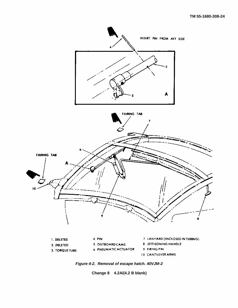
TM 55-1680-308-24
Figure 4-2. Removal of escape hatch. 40VJM-2
Change 8 4.2A/(4.2 B blank)

TM 55-1680-308-24
CAUTION
Ensure that all aircraft electrical power is turnedoff after positioning seat bucket to center oftravel.
b. Disarming of Seat Prior to Removal. Disarmthe ejection seat as follows:
(1) Ensure ground safety locks are installed.
(2) Disconnect drogue line from top of droguegun piston (3, figure 4-3) by removing bolt and nut (2)from special shackle (1).
(3) Remove lockwire securing drogue gunbarrel (5) to firing body (8) and remove lockwire andlead seal.
WARNING
Use extreme caution when removing droguegun barrel to prevent dropping the drogue guncartridge.
(4) Remove drogue gun barrel (5) from firingbody (8) using wrench, Part No WS1516
WARNING
Use extreme caution when removing droguegun cartridge, as cartridge has a percussion-type primer cap.
(5) Remove drogue gun cartridge, Part NoMBEU/7536, from drogue gun barrel (5) using extractor,Part No 105GT1046
NOTE
For handling of cartridge, refer to TM 9-1300-206.
(6) Reinstall drogue gun barrel (5) handtight infiring body (8) to prevent foreign matter from enteringbarrel.
WARNING
Never remove firing pin sear from primary firingmechanism until primary cartridge has beenremoved from primary cartridge breech. Anyattempt to do so will cause the cartridge to be firedEnsure that the firing pin sear is secured by thesafety pin when installing or removing the firingcables. Failure to do so will result in seriousinjury or death to maintenance personnel.
(7) With safety pin installed in firing pin sear (4,figure 4-4) of ejection gun primary firing mechanism, pushsear forward as far as possible and remove firing cables
(8) Remove lockwire securing primary firingmechanism (6) to primary cartridge breech (9). Removelockwire and lead seal
WARNING
When removing safety pin from firing pin sear ofejection gun primary firing mechanism, ensurefiring pin sear does not become dislodged. Neverremove safety pin from inside the flightcompartment, or while leaning over the ejectionseat or the ejection gun Removal of firing pin searfrom under firing pin will cause the ejection gun tofire.
(9) Carefully remove safety pin (5) from firing pinsear (4) on ejection gun primary firing mechanism.
(10) Unscrew primary firing mechanism (6) fromprimary cartridge breech (9) with spanner wrench, Part No128GT10155.
(11) Remove primary firing mechanism and innertube retainer collar (10, figure 44).
WARNING
Use extreme caution when removing and handlingprimary cartridge, as cartridge has a percussion-type primer cap. (Refer to TM 9-1300-206).
4-3

TM 55-1680-308-24
Figure 4-3. Drogue gun component location
4-4

TM 55-1680-308-24
Figure 4-4. Ejection gun firing mechanismcomponents
(12) Remove primary cartridge, Part No.MBEU/26434, from primary cartridge breech usingcartridge extractor, Part No GR506. (See figure 4-5 )
CAUTION
Do not install inner tube retainer collar at thistime.
(13) Reinstall primary firing mechanism (6, figure44) handtight in primary cartridge breech (9).
c. Preparation for Seat Removal.
(1) Withdraw top latch plunger by installinghandwheel, Part No. MBEU/26568, and turning clockwiseuntil handwheel bottoms. (See figure 46.)
NOTE
Do not remove handwheel unless ejection gun orplunger retaining tool, Part No. 4920-OV1-020, isplaced in position. The top latch plunger is held inthe plunger housing by the holding action of thehandwheel and/or ejection gun primary cartridgebreech or plunger retaining tool.
(2) Disconnect drogue gun/TCR initiator cableassembly trip rod (11, figure 4-3) by disconnecting quick-release pin (13) from ejection gun trip rod crossbeam (14).Install quick-release pin (13) in drogue gun safety pin hole.
(3) Remove screw, washer, and nut securingaircraft oxygen system hose clamp to ejection seat.Disconnect oxygen hose from ejection seat.
(4) Disconnect leg restraint cords by removing twoquick-release pins (9, figure 1-8) from floor fittings inaircraft.
CAUTION
Do not reinstall time release mechanism quick-release pin in ejection gun trip rod crossbeam untilejection seat is completely removed from aircraft.Failure to observe this procedure will result indischarging of the oxygen cylinder.
(5) Disconnect time release mechanism trip rod (2,figure 4-7) by removing quick-release pin (3) from ejectiongun trip rod crossbeam (4)
NOTE
On aircraft equipped with APX-72, ensure APX-72plug is disconnected prior to ejection seat removal.
Change 3 4-5

TM 55-1680-308-24
Figure 4-5. Primary cartridge removal
Figure 4-6. Top latch mechanism
Figure 4-7. Disconnecting time release mechanism triprod
d. Removal of Seat From Aircraft.
(1) Attach hoisting sling, Part No. 105GT1024-33,to ejection seat at four hoisting points (See figure 4-8.)
CAUTION
Ensure inner tube retainer and firing pin sear safetypin are removed prior to ejection seat removal.
4-6

TM 55-1680-308-24
Figure 4-8. Ejection seat hoisting points
(2) Position overhead hoist directly overejection seat and mate hoist hook to hoisting sling eyeon spring scale.
CAUTION
When removing ejection seat, do not exceed 200pounds on spring scale If ejection seat does notmove, ensure top latch plunger is completelywithdrawn If 200 pounds spring scale reading Isexceeded, perform special inspection. (Refer toparagraph 4-5a ).
(3) Take up tension until spring scale readsapproximately 150 pounds (white line on spring scale) andshake ejection seat with hands to break It free from itsmounting. (See figure 4-9 ).
(4) Grasp top of ejection seat and pull up sharplyRaise ejection seat approximately 12 inches.
Figure 4-9. Hoisting ejection seat with hoisting sling
Change 1 4-7

TM 66-1680-308-24
(5) Disconnect electrical lead to seat heightadjustment actuating jack at quick-disconnect on rightside of seat bucket (14, figure 1-2).
(6) Remove quick-release pin from emergencyoxygen system (15).
(7) Raise ejection seat with overhead hoist untilthe alignment tool can be extended. Extend alignmenttool and insert quick-release pin in alignment tool (figure4-11).
(8) Install rocket safety pin 134SEME10054 inhole of TCR motor initiator located under the seatbucket.
(9) Pull quick-release pin in rear of alignmenttool, Part No 105GT1024-59, and break alignment tool.Install alignment tool on top of ejection gun (figure 4-10).
(10) Install guillotine safety pin 134SEME10053in hole In the sear.
(11) Raise ejection seat until bottom of ejectionseat clears top of ejection gun. Disengage alignmenttool from ejection gun by lifting upward on release leverof alignment tool and remove alignment tool fromejection seat.
(12) Install ejection seat on seat cradle, Part No.105GT1040, as follows:
(a) Install transportation cradle mountingrail on section seat slippers (figure 4-14).
(b) Install mounting rail and ejection seat onseat cradle (figure 4-13).
(13) Remove hoisting sling from ejection seat.e. Disarming of Guillotine After Seat Removal.
WARNING
Never remove firing pin sear from guillotineinitiator firing mechanism until guillotinecartridge has been removed from guillotineinitiator breech Any attempt to do so will causethe cartridge to be fired. Ensure that firing pinsear is secured by the safety pin when installingor removing the manual override handle linkrod.
(1) With safety pin, Part No 134SEME10053 (7,figure 4-14), installed in sear (3) of guillotine firingmechanism (4), push sear up as far as possible, and
remove manual override handle connecting link rod (2)(2) Remove lockwire securing breech to tab
washer. Remove lead seal.
WARNING
Use extreme caution when removing breech toprevent dropping the guillotine cartridge.
(3) With safety pin (7) still in sear (3), removebreech (5) using tool, Part No. VSB2022.
WARNING
Use extreme caution when removing and handlingguillotine cartridge, as cartridge has a percussion-type primer cap. (Refer to TM 9-1 300-206.)
(4) Remove guillotine cartridge from breech (5)using extractor, Part No. 105GT1046.
(5) Reinstall breech (5) handtight into guillotineinitiator housing (6)
f. Removal of Telescopic Election Gun From Aircraft.
(1) Remove ejection gun upper clamp fittings onaircraft sloping bulkhead by removing locknut (1, figure 4-15), washer (2), and bolt (3).
(2) Remove locknut (4) and bolt (5) securingejection gun (6) to lower pivot and remove ejection gunfrom aircraft.
(3) Transport ejection gun and seat to authorizedwork area.
g. Removal Of Auxiliary Cartridges From TelescopicElection Gun.
(1) Remove auxiliary cartridges, Part No.MBEU/2923 1, from ejection gun as follows.
CAUTION
Do not attempt to break or pull lockwire fromauxiliary cartridge chamber cap or lockwire holesmay break out.
(a) Remove lockwire from lower auxiliarycartridge chamber cap.
(b) Carefully unscrew lower auxiliary cartridgechamber cap with spanner wrench, Pay No. 128GT101SS.(See figure 4-16.).
4-8 Change 1

TM 55-1680-30824
Figure 4-10. Alignment tool installed on ejection gun (extended position)
4-9

TM 55-1680-308-24
Figure 4-11. Alignment tool installed on ejectiongun (extended position)
WARNING
Although the auxiliary cartridges do not containpercussion-type primer caps, they are filled withan explosive powder which, if accidentally firedby either spark or flame, could cause death orserious injury.
(c) Remove auxiliary cartridge using cartridgeextractor, Part No GR506.
NOTE
Handle auxiliary cartridges In accordance withTM 9-1300-206.
Figure 4-12. Installation of transportation cradlemounting rail on ejection seat slippers
(d) Remove auxiliary cartridge seal fromcartridge chamber.
(e) Repeat preceding subsets (a) through (d)for removal of upper auxiliary cartridge.
4-10
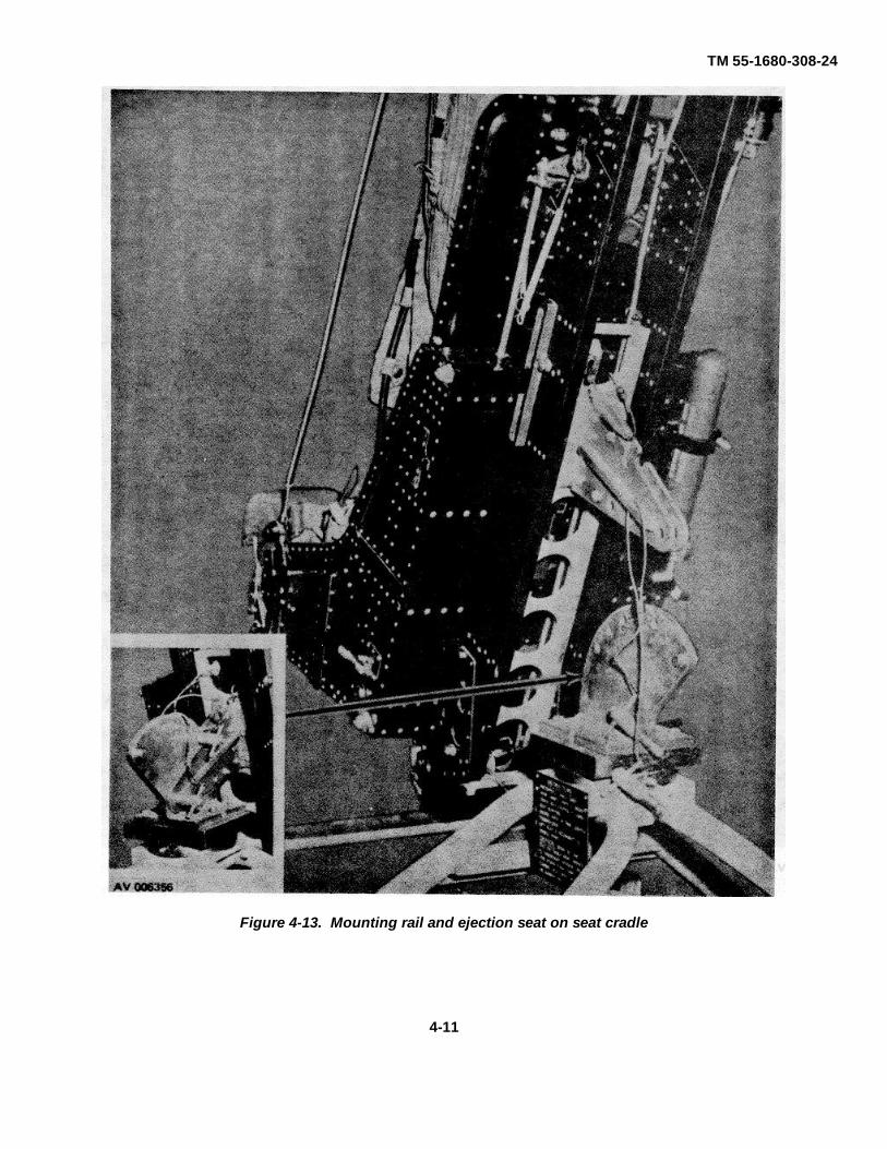
TM 55-1680-308-24
Figure 4-13. Mounting rail and ejection seat on seat cradle
4-11

TM 55-1680-308-24
Figure 4-14. Removal of manual override handle link rod
4-12

TM 55-1680-308-24
Figure 4-15. Location view of ejection gun mounting points
4-13

TM 55-1680-308-24
Figure 4-16. Removal of lower auxiliary cartridge
Section II. CHECKOUT AND ANALYSIS
4-4.General.
The following inspections shall be performed byDirect Support and General Support maintenance
4-5.Special Inspections.
Special inspections consist of visual Inspection andspecified checkout procedures to verify serviceabilitywhen an abnormal condition exists on the ejection seator the components of the ejection seat
a. Spring Scale Reading Exceeding 200 Pounds.When 200-pound spring scale reading occurs duringejection seat removal, proceed as follows
(1) Inspect top latch plunger for damage (Referto paragraph 5-7c )
(2) Inspect top latch plunger indicating dowel pinfor scoring.
(3) Check ejection seat slippers for properalignment. (Refer to paragraph 4-6r.)
(4) Verify proper clearances between the ejectiongun guide rails and slippers (Refer to paragraph 5-29 )
(5) Inspect seat lift points and lower portion ofejection seat bucket for damage and deformation
(6) Verify freedom of' movement of seat bucket
NOTE
Disconnect seat raising actuator and manuallyelevate and lower seat bucket.
4-14

TM 55-1680-308-24
(7) Verify proper operation of the manualoverride system. (Refer to paragraph 4-6b.)
NOTERelease of attachment points must be in propersequence.
(8) Upon receiving new or overhauled drogueguns or time release mechanisms, perform time delaychecks in accordance with paragraph 4-6k or 4-61, asapplicable.
b. Inspection requirement after guillotine has beeninadvertently fired: Replace activated guillotinecomponents.
CAUTIONThe guillotine components are not repairableafter firing. Burnt powder and gaseouscontaminants will cause severe corrosion.
c. Inspection requirement after ejection seat hasbeen fired: Replace ejection seat with serviceableassembly. The ejection seat is a "one-time" use itemand not recoverable after ejection.
d. Inspection requirement after M119 (TCR) rocketmotor has been fired: Replace ejection seat withserviceable assembly if ejected or severally damagedas a result of inadvertent rocket motor firing. Locallydispose of expended explosives and ejection seatcatapult assembly.
c. Inspection requirement after ejection seat hasbeen accidentally dropped onto a concrete, asphalt orequivalent surface:
(1) Dropped four (4) feet or less:
(a) Visually inspect structure for damage.
(b) Operationally test seat elevationmechanism through full seat travel. Replace motor ifbinding or erratic.
(c) Remove M-119 rocket motor andvisually inspect seat attachment brackets for damage. Ifdeformed or damaged, replace the ejection seat with aserviceable assembly.
NOTEM119 rocket motor is not renderedunserviceable by a four (4) foot drop.
(d) Inspect guillotine rigid tube for crushingat seat bottom. Replace if damaged.
(e) Inspect M119 rocket motor initiator cableand conduit for damage. Replace if conduit is crushed.
(f) Lift lowering line thigh pads and inspectfiberglass supports for damage. Replace thigh supports ifdamaged.
(g) Remove main parachute pack and inspectfor exterior damage. Return to parachute repack area ifdamage is observed.
(h) Remove time release mechanism andfunctionally test barostat. Replace barostat if altitudediffers by 2,000 feet or more from previous reading.
(i) Verify freedom of motion (opening) ofscissor shackle with time release mechanism removed.
(j) Using four (4) foot straight edge, verifymain beam structure alignment by placing straight edgeagainst main beam inner surface. Surface to surfacecontact should occur. Replace seat if main beams fail thisinspection.
(2) Dropped more than four (4) feet but less thaneight (8) feet.
(a) Accomplish all checks of paragraph 4-5e(1)above.
(b) Replace M119 rocket motor.(c) Accomplish time release mechanism
functional tests.
(d) Accomplish drogue gun functional tests.
(e) Remove and inspect RSSK contents fordamage.
(f) Operationally test all linkage for properoperation.
CAUTIONIf rocket motor brackets are damaged or deformedthe seat must be replaced.
(g) Remove withdrawal line from guillotine andinspect line for cut-damage from guillotine blade. Replacewithdrawal line if protective sleeve has been cut through.
(3) Dropped from a height In excess of eight (8)feet.
(a) Forward M119 rocket for explosiveordnance disposal.
(b) Remove drogue parachute assemblyexcluding the Hardshell container, and forward to repackfacility for inspection and reuse.
Change 3 4-15

TM 55-1680-308-24
(c) Remove main parachute pack assemblyand forward to repack facility for Inspection and re-use.
(d) Remove survival kit contents fromRSSK and inspect for subsequent use in replacementejection seat.
NOTEThe RSSK (complete with contents bag), dropline and fry pan are to remain with the ejectionseat as an assembly.
(e) Replace with a serviceable assembly.
NOTEPlace unserviceable ejection seat in the cratereceived and tag the unserviceable "dropped inexcess of eight (8) feet."
(f) Package ejection seat records withdamaged seat.
4-6. One-Hundred Eighty Day Inspection.
NOTEA 10-day maximum free period may be utilizedbefore deducting from the next scheduledejection seat inspection cycle in the eventaircraft maintenance actions prevent timelyinstallation. If held in an area away from normalseat maintenance, a suitable covering and allsafety pins shall be utilized. Perform 180-dayinspection as follows:
a. Cartridge and Rocket Motor Expiration DateInspection. Check all cartridges and rocket motor forexpiration date If new cartridges or rocket motors are tobe installed, mark each item with expiration date andejection seat serial number in black permanent markingink Enter expiration and installation dates on applicableDA Form 2408-18. Cartridges and rocket motors withless than 180 days service life remaining must bereplaced with serviceable items, or the next scheduledseat inspection must be adjusted to correspond with theremaining life of installed explosives.
b. Functional Check of Manual Override System.
WARNINGEnsure that guillotine cartridge has beenremoved from guillotine breech initiator.
(1) Position manual override handle (7, figure2-1) in its down (locked) position.
(2) Ensure that spring-loaded leg restraint cordlock release handle (6) is in its forward position.
(3) Ensure loop straps lugs are inserted in harnesslock of the inertia reel mechanism.
(4) Ensure that the rigid seat survival kit restraintlugs are locked to the seat bucket.
(5) Ensure leg restraint cords (2, figure 1-8) areretained by cord lock fittings (6).
(6) Ensure that the face blind locking mechanismlatch is in the down or unlocked position.
(7) Ensure that the lower firing handle safety is inthe down or unlocked position.
(8) Install manual override link rod in guillotineinitiator sear.
(9) Slowly move manual override handle (7, figure2-1) to up-(unlocked) position.
NOTEThe following events should occur in the order listed oradjustment of the initiator link rod lower adjustment rodtube will be required.
(a) Guillotine initiator sear should be withdrawnfrom its firing mechanism.
(b) Leg restraint cords should release from legrestraint cord locks.
(c) Survival kit rigid seat restraint lugs shouldbe released from the seat bucket.
(d) Loop straps lugs should release fromharness lock mechanism.
(e) Upper and lower firing handles should lock.
NOTEThe upper and lower firing handles do not have tolock in any given sequence.
This function is satisfactory if the two handles are lockedwhen the manual override handle is in the full up (unlocked)position.
(10) If retention points do not release in sequence,refer to paragraphs 4-15b and 5-18
c. Function Check of Sticker Strap Spring Clip.
(1) Push sticker strap lugs into their respectivespring clips on each side of the ejection seat.
4-16 Change 4

TM 55-1680-308-24
(2) Attach a spring scale into strap end ofsticker strap lugs and pull on spring scale, noting springscale reading, until each sticker strap lug releases fromspring clips. Release tension shall be 35±15 pounds.(See figure 4-17.)
(3) If release tension is not within tolerance,refer to paragraph 5-28c for corrective action.
d. Removal of Time Release Mechanisms.
(1) Ensure that time release mechanism iscocked.
Keep hands clear of area below time releasemechanism plungers. Plungers extend withgreat force.
(2) Disconnect bungee from time releasemechanism trip rod (2, figure 4-7).
(3) Carefully support time release mechanism andremove three nuts and three washers from mounting studs.
CAUTION
Use caution when removing time releasemechanism to prevent bending the upper plungerrod in the scissor release plunger housing.
(4) Slide time release mechanism down whileturning it outward, only as much as necessary, until upperplunger rod is clear of guard and guide tubes.
Change 4 4-16A

TM 55-1680-308-24
Figure 4-17. Sticker strap spring clip check
e. Removal of Drogue Gun.
(1) Remove bungee (16, figure 4-3) fromdrogue gun/TCR cable trip rod (11).
(2) Ensure that special shackle has beenremoved from drogue projectile.
(3) Remove drogue gun barrel (5) from body (8)which was left handtight and ensure cartridge has beenremoved. Reinstall barrel handtight.
NOTE
If drogue gun barrel is not handtight, refer toparagraph 4-3b.
(4) Disconnect TCR cable (15) from lower endof drogue gun/TCR cable trip rod (11) by removingcotter pin, flathead pin (12).
(5) Remove nuts and washers (7) from studs(6) in seat securing drogue gun and pull drogue gunoutboard to remove from studs (6) and seat.
f. Remove of Personnel Parachute Container.
(1) Position manual override handle to up(unlocked) position and pull out loop strap (3, figure 1-
7). Disconnect parachute roller yokes (4).
(2) Remove the personnel parachute withdrawalline from the shackle at the scissor on top of the seat.
(3) Pull the withdrawal line retaining pins from bothsides of the head box releasing the personnel parachuterestraint straps.
(4) Remove the withdrawal line from the guillotinecutter head assembly by pulling the yellow guard outboardfrom the seat.
(5) Remove restraint straps from spreaders atcentral support bracket.
CAUTION
Caution should be taken when transportingparachutes between maintenance activities toinsure damage does not occur. Consult TM 10-1670-201-23, Chapter 4, for shipmentrequirements.
(6) Lift personnel parachute container (6, figure 1-2) from ejection seat; forward personnel parachute pack toparachute support facility.
NOTEWhen cross-servicing the personnel parachute anddrogue parachute systems, ensure inspection,maintenance, and repack procedures areperformed in accordance with TM 10-1670-250-20.
g. Removal of Rigid Seat Survival Kit (RSSK).
NOTE
Ensure that guillotine has been disarmed.
(1) Remove seat, back, and thigh supportcushions.
(2) Position manual override handle to up(unlocked) position.
(3) Pull up on retention strap (8, figure 1-2) andforward portion of seat pan to remove RSSK from seatbucket.
4-16B Change 8

TM 55-1680-308-24
h. Remove of Drogue Parachute HardshellContainer.
(1) Withdraw upper (thick) cable through pocketon flap of drogue parachute Hardshell container.
(2) Ensure that special shackle nut and bolt arefingertight.
(3) Remove screw, spacer washer, washer, lockwasher and nut from each side of drogue parachutecontainer and lift Hardshell container from ejection seat,using lift loops on outer edges of Hardshell container.
(4) Dispatch drogue parachute and Hardshellcontainer assembly to parachute support facility fortopriate action.
(5) Loosely install hardware removed fromHardshell container installation into ejection seat headbox holes to preclude loss.
i. Remove of Emergency Oxygen Cylinder.
(1) Disconnect oxygen cylinder (13, figure 1-9)from oxygen linkage by removing quick-release pin (25)that secure cable link (29) to bellcrank (24)
(2) Disconnect oxygen hose (6) from oxygenquick disconnect bridle and lanyard (5) by pulling on thebridle.
(3) Loosen adjusting nut (14), open clamp (1),and lift oxygen assembly out of oxygen cylinder supportbacket (11).
Functional Check of Face Blind and Locking
WARNING
The operational check of the face bind should only beaccomplished when the ejection seat has beendisarmed.
(1) Remove face blind locking mechanismsafety pin.
(2) Check that face blind cannot be pulled fromits receptacle with locking mechanism m up (locked)position.
(3) Position face blind locking mechanism indown unlocked position. Grasp face blind handle andpull face ad to its full extension.
(4) Check that spring-loaded locking plungersof face blind handle release smoothly from their
receptacle.
(5) Check firing cable extension for freedom frombinding and retention of face blind restraint strap by link linequick-release pins.
(6) While holding face blind handle at fullextension, check that each locking plunger retracts fully.
(7) Deleted.
(8) Check for general condition, signs of wear,fraying, or corrosion of metallic parts.
(9) With face blind fully extended, the upper firingcable must withdraw the primary firing mechanism sear.
(10) Inspect firing cable for kinks, broken wires, andcorrosion.
(11) Ensure upper firing (truck) cable is securelyattached to face blind.
(12) Face blinds and locking mechanisms which donot meet this criteria must be replaced. (Refer toparagraph 5-6.)
k. Drogue Gun Inspection.
NOTEIf one year requirements defined in paragraph 4-7are due, accomplish at this time.
(1) Remove drogue gun barrel.
(2) Perform a firing pin protrusion check on thedrogue gun as follows:
(a) Pull trip rod (11, figure 4-3) to unlockdrogue gun.
(b) Install drogue gun body on holding tool,Part No. 10SGT1027.
(c) Check firing pin protrusion using firing pinprotrusion tool, Part No. 105GT1029. Firing pin mustprotrude 0.109 (+0.031, -0.015) inch. (See figure 4-18.)
(3) Perform a firing spring compression check onthe drogue gun as follows:
(a) Install drogue gun on holding tool, Part No.105GT1027, and mount holding tool securely in a vise.
(b) Remove access bolt from end plug (6,figure 4-19).
Change 8 4-17

TM 55-1680-308-24
Figure 4-18. Drogue gun firing pin protrusion check.
4-18

TM 55-1680-308-24
Figure 4-19. Installing cocking tool in drogue gun
(c) Insert drogue gun cocking tool (5), Part
No. MBEU/4341, into end plug hole in base of firing body(1).
(d) Carefully locate tapped hole in firing pin (2)with threaded end of cocking tool (6) by oscillating cockingtool until it can be screwed into tapped hole.
(e) Attach a spring scale to shank of cockingtool with lockwire. (See figure 4-20).
(f) With spring scale In line with cocking tool,pull back on spring scale. The firing pin must not start tomove until spring scale reads approximately 8 to 15pounds.
NOTEInitial firing pin movement may be detected byinserting finger in opening of drogue gun body andlightly resting finger on firing pin.
(4) Replace drogue gun if spring compression doesnot fall within allowable limits.
(5) Cock the drogue gun as follows:
(a) Place sear in firing body (8, figure 4-3)Lock sear in place by pushing In on locking plungerassembly (4, figure 4-19).
NOTEThe ground lock pin or tool, Part No. 105GT1044,may be used for this purpose.
(b) Ensure that locking plunger assembly.
(4) is properly positioned by inserting ground lockpin (9, figure 4-3) in safety pin hole.
NOTEIf ground lock pin will not enter safety pin hole, thelocking plunger assembly is not in its properposition.
(c) After properly positioning locking plungerassembly (4, figure 4-19), remove ground lock pin (9, figure4-3) from safety pin hole.
(d) Holding firing body (1, figure 4-19) firmly,pull cocking tool (5) against firing spring tension as far aspossible.
(e) Release tension on cocking tool and, aftera very slight return motion (approximately 1/8 inch), firingpin will lock In the cocked position.
Change 2 4-19

TM 55-1680-308-24
Figure 4-20. Firing pin spring compression test
NOTEDuring cocking the firing mechanism must move freely (except for the spring tension), and the locking plungerassembly will raise and then lower to the locked position, holding the sear firmly in position. The escapementmechanism operation will be audible during the cocking action.
(f) Ensure firing pin does not protrude. Unscrew cocking tool and remove from tapped hole in firing body(1).
(6) Perform a drogue gun time delay check using test umt, Part No. 134GT1041-T5; holding tool, Part No.105GT1027; and a 110-volt ac, 60 Hz power source as follows:
NOTETest unit, Part No. 134GT1041-T5, consists of a timing clock assembly, Part No. 134GTI041-35, a start switchassembly, Part No. 105GT1030-13; a stop switch assembly, Part No. 1OSGT1030-11; and a barostat adapterassembly, Part No. 105GT1030-23.
(a) Ensure drogue gun is cocked and that firing pin does not protrude.
(b) Install drogue gun on holding tool and mount holding tool securely in vise.
(c) Attach start switch assembly over locking plunger assembly. (See figure 4-21.)4-20

TM 55-1680-308-24
Figure 4-21. Drogue gum time delay check test setup
(d) Install stop switch assembly In firing pinend of firing body (1, figure 4-19).
(e) Insert plugs of start and stop switchassemblies into proper jacks in relay control section oftiming clock assembly.
(f) Connect timing clock assembly to a110-volt ac, 60 Hz power source.
(g) Apply power to timing clock assemblyby setting toggle switch to ON. Indicator light next totoggle switch will illuminate.
NOTEIf timing clock assembly starts when toggleswitch is positioned to ON, the start and stopswitch assembly has been incorrectly installedor is out of adjustment.
(h) Ensure that timing clock assembly is setto zero. If necessary, depress reset lever on timingclock assembly to reset clock.
(i) Pull sear from drogue gun firing body.Timing clock assembly will start and stop.
(j) Check clock for time delay of 0 40 to 0.60seconds on drogue gun
(k) Repeat time delay check two additionaltimes.
(7) If drogue gun falls to meet the time delayspecified In preceding substep (j), replace drogue gun.
NOTEPrior to installing a new or newly over-hauleddrogue gun assembly accomplish all tests withinparagraphs 4-6k(1) through 4-6k(7)(c) herein.
(a) If test was satisfactory, remove test unitand holding tool from drogue gun.
(b) Recock the drogue gun.
Change 2 4-21

TM 55-1680-308-24
CAUTION
Ensure that the cocking tool is pulled full backas noted by the 1/8 over travel and audible gearmovement
(c) Install access bolt into end plug (6,figure 4-19 )
I. Time Release Mechanism Inspection.
(1) Time release mechanism time delayoperational test.
(a) Mount time release mechanism onholding tool, Part No 105GT1027, and secure holdingtool in a vise with the time release mechanism in ahorizontal position.
CAUTION
Do not allow harness release plunger to extendduring timing tests, only the rack plunger needextend Damage to the timing mechanism can
result if this procedure is not followed.
(b) Uncock the time release mechanism.
(c) Using test umt, Part No 134GT1041-T5,install time release start and stop switch assembly on timerelease mechanism and secure with knurled knob (Seefigure 4-22.)
NOTE
Test unit, Part No. 134C;T1041-T5, consists of atiming clock assembly, Part No 134GT1041-35,and a start and stop switch assembly, Part NoIOSGT1031-21.
(d) Connect plugs of start and stop switchassembly to their respective jacks on relay control sectionof timing clock assembly.
(e) Connect timing clock assembly to a 110-volt ac, 60 Hz power source, and position toggle switch toON position Indicator light next to toggle switch willIlluminate.
Figure 4-22 Time release mechanism time delay test setup4-22

TM 55-1680-308-24
NOTEIf timing clock assembly starts when toggleswitch is positioned to ON, the start and stopswitch assembly has been incorrectly installedor is out of adjustment.
(f) Ensure timing clock indicates zero. Ifnecessary, depress reset lever on timing clock assemblyto reset clock.
(g) Accomplish the following procedures tomake a coarse adjustment on the start and stop switchassembly.
1. Manually depress start switch and adjuststop switch until timing clock stops.
NOTECock only the rack plunger.
2. Insert sear and cock time releasemechanism using cocking tool.
3. Adjust start switch by loosening thumbscrewand move start switch in until timing clock assemblyruns.
4. Move start switch out until timing clockassembly stops. Tighten thumbscrew.
5. Depress reset lever on timing clockassembly to reset clock to zero.
(h) Accomplish the following procedure tomake a fine adjustment on the start switch assembly:
1. Screw out adjusting screw until timing clockassembly runs.
2. Screw in adjusting screw until timing clockassembly stops.
3. Depress reset lever on timing clockassembly to reset clock to zero.
(2) Time release mechanism test procedure.
(a) Grasp trip rod of time releasemechanism and pull sear Rack plunger will extend andtiming clock assembly should start and stop.
(b) Check clock for time delay of 1.65 to1.85 seconds.
(c) Recock time release mechanism, recheckinstallation of start and stop switch assembly, and repeatpreceding subsets (a) and (b) two more times. Replace anytime release mechanism that does not meet the specifiedtime requirements.
NOTEPrior to installing a new or newly overhauled timerelease mechanism accomplish all tests withinparagraphs 4-61(1) through 4-61(3) (k) herein.
(d) Position toggle switch of timing clockassembly OFF. Cock both plungers of the time releasemechanism and remove start and stop switch assemblyfrom time release mechanism.
NOTEDo not remove time release mechanism fromholding tool as it is required during the barostatoperational check.
(e) With both plungers cocked, check freedomof movement of the plungers by pressing inward. The rackplunger should retract and return to the locked position withan audible gear movement (whirring) sound The harnessrelease plunger.being spring-loaded, should retract and extend withoutbinding.
NOTEThere should be approximately 1/4-inch of travel ofthe rack plunger, and 1/2-inch travel on the harnessrelease plunger.
(3) Barostat check procedures. Barostatoperational check of time release mechanismsincorporating a standard barostat assembly (MBEU690J5).
NOTEThese procedures apply to use of the barostatadapter assembly (P/N 105GT1030-23) withseparate vacuum source and altimeter.
(a) Ensure time release mechanism is cocked.(b) Remove lockwire and lead seal from
barostat assembly.(c) Install barostat adapter assembly, Part No.
105GT1030-23, over time release mechanism barostatassembly. (See figure 4-23.)
NOTEEnsure barostat adapter assembly is securely heldto barostat assembly by retainer clips.
Change 3 4-23

TM 55-1680-308-24
(d) Connect vacuum adapter tee fitting onbarostat adapter assembly to vacuum pump, FSN4310-671-4481, and to pressure altimeter, Part No.MS28044L1A.
CAUTION
Ensure pressure altimeter is set to 29.92 inches(standard sea level) before beginning tests.
4-24 Change 4

TM 55-1680-308-24
Figure 4-23. Time release mechanism barostat test setup.
(e) Ensure bleeder valve on barostat adapterassembly is closed. Set pressure altimeter hands to fieldelevation.
(f) Slowly open bleeder valve until pressurealtimeter indicates 19,000 to 20,000 feet. Hold vacuumat this altitude for approximately one minute.
CAUTIONDo not allow harness release plunger to extendduring test; only the rack plunger need extend.Damage to the timing mechanism can result ifthis procedure is not followed.
(g) Grasp trip rod and pull sear from time releasemechanism. Plunger must not extend.
NOTERestrain harness release plunger with cockingtool to preclude rapid extension
(h) Watching the pressure altimeter closely, slowlyrelease vacuum from barostat assembly, using bleedervalve, and note the altitude on the pressure altimeterwhen rack plunger starts to move. The rack plungershould start its extension at an altitude range of 15,500to 14,000 feet.
NOTERecord altimeter reading for time release
mechanism by serial number for subsequent testreviews.
Change 2 4-24A/(4-24B blank)

TM 55-1680-308-24
WARNINGA barostat which exhibits a 2,000 feet ormore change (decrease in altitude) fromthat previously recorded shall be replacedwith a serviceable barostat Refer toparagraph 5-23.
(i) Recock time release mechanism and repeatpreceding substeps (e) through (h) two more times.
NOTEDo not cock harness release plunger.
NOTEA barostat that does not operate atthe prescribed altitude may beadjusted In accordance withparagraph 5-23(h).
(j) Remove barostat adapter assembly from barostatassembly. Recock both plungers on time releasemechanism
(k) Secure serviceable barostat assembly withlockwire and lead seal (items 1 and 3, table 12)
(4) Barostat check procedures utilizing vacuum testbox (TD01153). Barostat operational check of timerelease mechanisms incorporating a standard barostatassembly (MBEU690J5).
(a) Lift cover of test box and check inner area fordirt and contamination, clean as required
(b) Check lid seal for damage and wipe with a cleanlint free cloth to remove
(c) Remove trip rod and sear from time releasemechanism to be tested.
CAUTIONBefore installing time releasemechanism, ensure barostat adjustmentscrew driver mechanism and test boxfiring control are fully withdrawn.
(d) Insert time release mechanism into vacuum testbox, locating it on the two mounting pins, and secure inposition with clamp. Tighten clamp nut securely usingspanner wrench provided.
CAUTIONOnly the time release RACK plunger(SHORT) shall be cocked to perform thistest
(e) Fully insert the special firing pin attached to thefiring cable and cock the RACK PLUNGER only usingthe cocking tool.
(f) Lower the vacuum box lid down onto the matingsurface making sure the seal uniform makes contact.
(g) Adjust altimeter to read standard "sea level"(29.92 INCHES OR 1013 MILLIBARS) to assure all testresults are independent of elevations and/or fieldelevations.
CAUTIONDo not use force when closing the airadmittance valve to preclude damagingthe seal.
(h) Move the ON/OFF switch to ON and verify thered indicator light illuminates and the vacuum motorstarts.
(i) Apply a moderate hand pressure to top of lid andcarefully close air admittance valve Observe thataltimeter begins recording an increase in altitude.
(j) Allow vacuum motor to run until an altitudereading of 25,000 to 30,000 feet is attained, and thenturn switch OFF.
NOTEWhen vacuum motor is turned OFF thealtimeter may fluctuate momentarily If altitudecontinues to decrease, the lid seal is most likelyupset, or a test box control seal may be worn.
(k) Hold at this altitude for approximately oneminute and remove time release mechanism gear bydepressing the firing control knob. At this point the timerelease must not operate.
(I) Slowly open the air admittance valve by rotatingcounter clockwise until the altimeter shows a steady fallof 200 feet per second (MAXIMUM), and note thealtitude at which the time release mechanism begins tooperate.
NOTETime release mechanism operation isnoted by an audible operation of thegearing and visible movement of theRACK PLUNGER.
(m) Record the altitude at which time releasemechanism operation began. The altitude reading at thefirst motion shall be 14,500 feet plus or minus 500 feet.
WARNINGA barostat which exhibits a 2,000feet or more change (decrease inaltitude) from that previouslyrecorded shall be replaced with aserviceable barostat Refer toparagraph 5-23.
Change 2 4-25

TM 55-1680-308-24(n) Evacuate the vacuum chamber by opening the
air admittance valve and repeat this test two moretimes.
CAUTIONWhen evacuating the vacuum changer, do notexceed 1,000 feet per second decrease Inaltitude to prevent damage to altimeter.
(o) A barostat that does not operate at theprescribed altitude may be adjusted in accordance withparagraph 5-23(h).
(p) Remove serviceable time release mechanismfrom vacuum test chamber and cock both plungers forinstallation on ejection seat.
NOTE Record altitude reading for time releasemechanism by serial number for subsequent testreviews.
m. Primary Firing Mechanism Inspection.
(1) Remove primary firing mechanism fromejection gun.
(2) Using firing pin cocking tool, Part No.MBEU/1321, remove firing pin sear. (See figure 424.)
(3) Ensure that firing pin sear moves freely in firingpin slot.
(4) Place firing pin sear on a flat surface andinspect for deformation.
NOTEIf the firing pin sear is bent orcracked, replacement is required.
(5) Check Initial compression of primary firingmechanism spring using a spring scale attached to firingpin cocking tool. Firing pin must not move until a load ofat least 8 pounds is applied..
CAUTIONDo not attempt to alter spring tension by adding orremoving washers.
(6) Check firing pin protrusion with firing pinprotrusion tool, Part No 105GT1029. The pin protrusionshould be 0.109 (-+0 030, -0.015) inch. (See figure 4-25.) If firing pin does not protrude to the abovedimensions, refer to paragraph 5-3.
(a) Deleted.(b) Deleted.(c) Deleted.(e) Deleted.(f) Deleted.
n. Ejection Gun Inspection.
CAUTIONNo lubricant should be present or be appliedto guide rails. Guide rails should always bekept clean and dry.
(1) Inspect ejection gun guide rails (6, figure 4-26)for scoring, gouges, and cleanliness.
4-26 Change 2
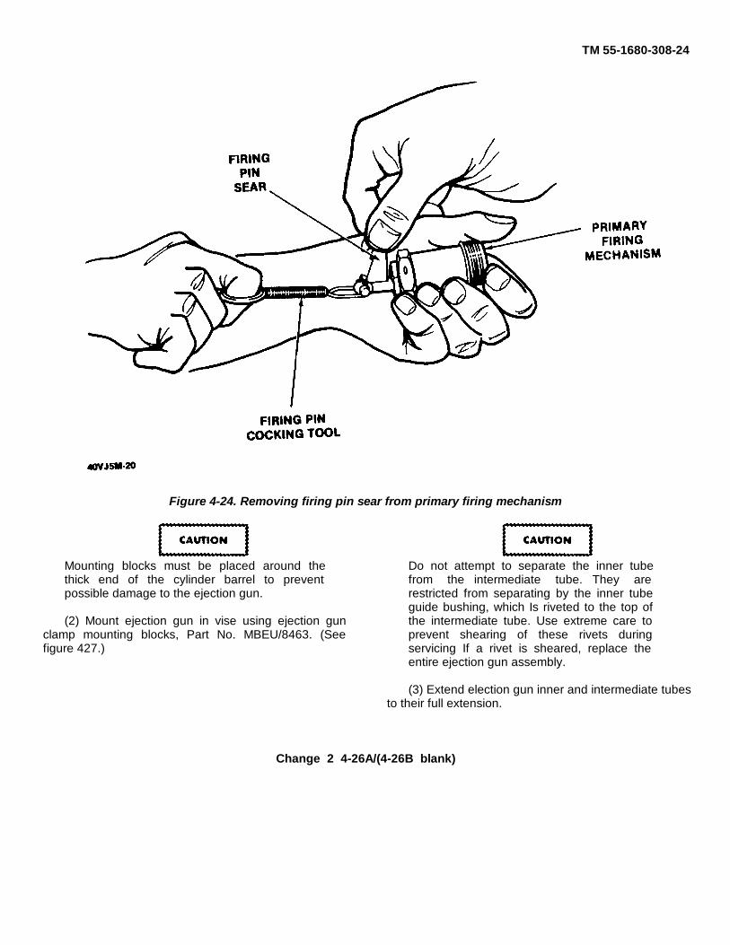
TM 55-1680-308-24
Figure 4-24. Removing firing pin sear from primary firing mechanism
Mounting blocks must be placed around thethick end of the cylinder barrel to preventpossible damage to the ejection gun.
(2) Mount ejection gun in vise using ejection gunclamp mounting blocks, Part No. MBEU/8463. (Seefigure 427.)
Do not attempt to separate the inner tubefrom the intermediate tube. They arerestricted from separating by the inner tubeguide bushing, which Is riveted to the top ofthe intermediate tube. Use extreme care toprevent shearing of these rivets duringservicing If a rivet is sheared, replace theentire ejection gun assembly.
(3) Extend election gun inner and intermediate tubesto their full extension.
Change 2 4-26A/(4-26B blank)
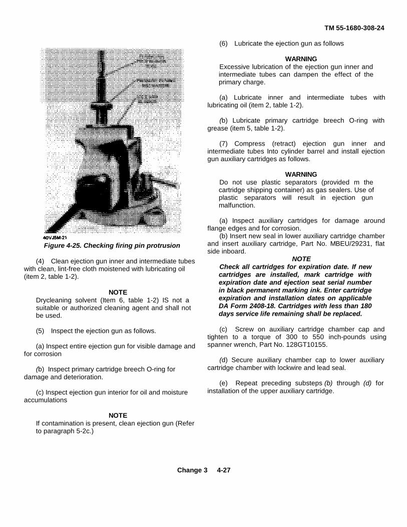
TM 55-1680-308-24
Figure 4-25. Checking firing pin protrusion
(4) Clean ejection gun inner and intermediate tubeswith clean, lint-free cloth moistened with lubricating oil(item 2, table 1-2).
NOTEDrycleaning solvent (Item 6, table 1-2) IS not asuitable or authorized cleaning agent and shall notbe used.
(5) Inspect the ejection gun as follows.
(a) Inspect entire ejection gun for visible damage andfor corrosion
(b) Inspect primary cartridge breech O-ring fordamage and deterioration.
(c) Inspect ejection gun interior for oil and moistureaccumulations
NOTEIf contamination is present, clean ejection gun (Referto paragraph 5-2c.)
(6) Lubricate the ejection gun as follows
WARNINGExcessive lubrication of the ejection gun inner andintermediate tubes can dampen the effect of theprimary charge.
(a) Lubricate inner and intermediate tubes withlubricating oil (item 2, table 1-2).
(b) Lubricate primary cartridge breech O-ring withgrease (item 5, table 1-2).
(7) Compress (retract) ejection gun inner andintermediate tubes Into cylinder barrel and install ejectiongun auxiliary cartridges as follows.
WARNINGDo not use plastic separators (provided m thecartridge shipping container) as gas sealers. Use ofplastic separators will result in ejection gunmalfunction.
(a) Inspect auxiliary cartridges for damage aroundflange edges and for corrosion.
(b) Insert new seal in lower auxiliary cartridge chamberand insert auxiliary cartridge, Part No. MBEU/29231, flatside inboard.
NOTECheck all cartridges for expiration date. If newcartridges are installed, mark cartridge withexpiration date and ejection seat serial numberin black permanent marking ink. Enter cartridgeexpiration and installation dates on applicableDA Form 2408-18. Cartridges with less than 180days service life remaining shall be replaced.
(c) Screw on auxiliary cartridge chamber cap andtighten to a torque of 300 to 550 inch-pounds usingspanner wrench, Part No. 128GT10155.
(d) Secure auxiliary chamber cap to lower auxiliarycartridge chamber with lockwire and lead seal.
(e) Repeat preceding substeps (b) through (d) forinstallation of the upper auxiliary cartridge.
Change 3 4-27

TM 55-1680-308-24
Figure 4-26. Ejection gun - exploded view (Sheet 1 of 2)

TM 55-1680-308-24
(10) Ensure that guillotine initiator (8) is secured toseat bucket.
p. Guillotine Initiator Firing Pin Inspection.
(1) Ensure that guillotine initiator was disarmed whenseat was removed from aircraft. Refer to paragraph 43e.
(2) Remove link rod (6, figure 4-28) by using firing pincocking tool, Part No. MBEU/1321, and remove firing pinsear (12).
NOTE
The firing pin sear must move freely firing pin slot.
(3) Place firing pin sear on flat surface and inspect fordeformation.
NOTE
Replace firing pin sear if it is bent or cracked.
(4) Check initial compression of guillotine initiator firingmechanism (13) spring by securing mechanism intopadded vice jaws and using a spring scale attached tofiring pin cocking tool. Firing pin must not move until a loadof at least 8 pounds is applied.
NOTEPlunger should be flush or slightly protruded.
(5) Check firing pin protrusion with firing pin protrusiontool J9126 by inserting tool into guillotine cartridge breech(6, figure 4-29). If firing pin does not cause gage plunger tobe flush or protrude slightly, proceed as follows:
(a) Remove firing pin assembly by bending downtabs of tab washer (2) that secures retaining collar (3).
(b) Remove retaining collar (3), tab washer (2),firing pin spring (4), and firing pin (5).
(c) Inspect firing pin for burrs and bending.
(d) Clean cartridge breech with dry, filtered,compressed air to remove possible foreign matter.
(e) Lubricate firing pin with a light coat oflubricating oil (item 2, table 1-2).
(f) Screw retaining collar (3) into guillotinecartridge breech (6).
(g) Bend tab to make contact with flat surface ofguillotine cartridge breech (6).
(h) The tab to be bent flat on the guillotine cartridgebreech should be opposite tab engaged in retaining collarslot
(i) Repeat preceding substeps (a) through (h) If thepin does not extend the required amount, replace the firingmechanism
(j) Install right thigh support with screws and replacepadding by pressing down firmly
q. TCR Motor (MI 19) and Cable DispenserInspection.
(1) Inspect TCR cable dispenser (2, figure 4-30) forsecure installation on seat.
(2) Inspect visible dispenser cable (3) for kinks, nicks,or fraying
(3) Inspect TCR motor cable conduit (1) for sufficientslack, kinks, gouges, and security to seat.
The TCR cable conduit must have a generousloop coming out of dispenser and a loopapproximately 7 to 7-1/2 inches at the motor toassure free cable travel
(4) Inspect TCR initiator cable small con- nector forsecurity of lockwire at TCR dispenser housing and largeconnector for security of lockwire at TCR motor Initiator
Figure 4-29 Guillotine initiator - exploded view
Change 5 4-31

TM 55-1680-308-24
Figure 4-30. TCR motor and cable dispenser inspection
4-32
TM 55-1680-308-24
(5) Inspect TCR motor (7) for security of installationTCR motor nozzle must be seen through bracket (6)hole, and be free of obstruction.
(6) Ensure safety lock streamer (134SEME10054)is installed.
(7) Inspect TCR motor (Ml 119) for expiration ofinstalled life.
r. Slipper Alignment and Calibration Check.
NOTE
Although the ejection gun and ejection seatare individually replaceable, the calibrationcheck should be accomplished. on matedejection guns and ejection seats to precludeunnecessary removal of main beam materialIf replacement of ejection gun and electionseat is necessary, reidentification to matedassemblies (by identification number) shouldbe accomplished in accordance withparagraph 5-32 before installation
(1) Remove election seat from seat cradle andsupport ejection seat using hoisting sling, Part No105GT1024-33, and a suitable hoist
Do not attempt to remove slipper material.Removal of material could result m ejectionseat failure during ejection or crash landing.
(2) Inspect slippers for evidence of corrosion ormetal bum. Replace defective slippers.
(3) Perform slipper calibration check as follows:
(a) Using an outside micrometer, measure thedistance across inserts (I, figure 4-26) at top of ejectiongun. Record this reading.
(b) Tighten top slippers In main beam toproper torque (50 to 60 Inch-pounds) Using an insidemicrometer, measure the distance between top slippersat point of minimum dimension.
(c) Compare ejection gun and slipper
readings, and adjust as necessary, using either of thefollowing methods
Maximum allowable spot face of main beammaterial for middle and top slippers is 0 050 incheach beam maximum allowable spot face ofmain beam material for lower slippers is 0010Inch each beam. The left and right beams mustbe spot-faced an equal amount
1. Insufficient clearance. Remove top slippersfrom main beam. Remove necessary shuns (if any) anduse spot-facing tool, Part No 134XM15499 or TD0/742,to spot-face slipper attachment holes on inside of mainbeam until a micrometer reading of 0001 to 0006 inch isestablished between ejection gun and slippers.
2. Excessive clearance. If the clearance exceeds0006 inch, install shims between slippers and insideface of each beam
NOTE
Install equal thickness of shims betweeneach slipper and inside face of each mainbeam
(d)Repeat preceding substeps (a) through (c) forthe center and bottom set of slippers The clearancemust be as follows:
NOTE
The outside diameter of the ejection gunmust be measured where the slippers matewith the ejection gun.
1. Middle slippers 0.010 to 0.012 inch
2. Bottom slippers 0 000 to 0.005 inch.
Ensure that locating pin slot of the ejection gun innerbarrel aligns with the main beam locating pin.
Change 1 4-33
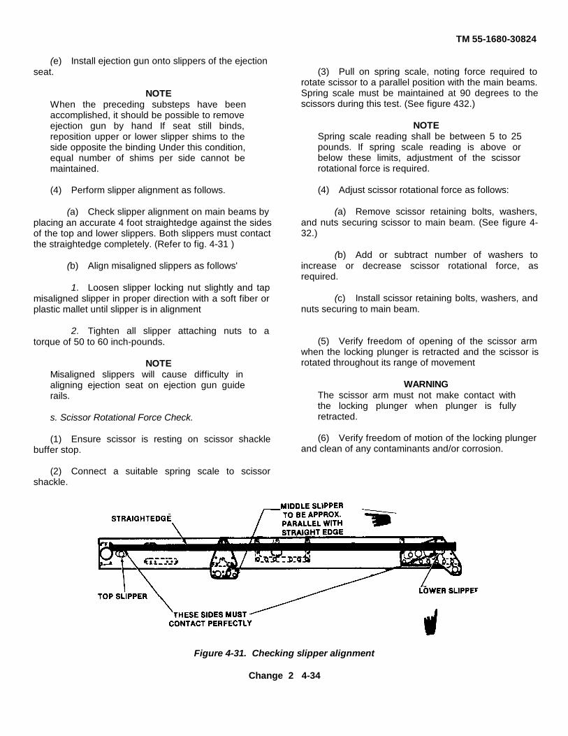
TM 55-1680-30824
(e) Install ejection gun onto slippers of the ejectionseat.
NOTEWhen the preceding substeps have beenaccomplished, it should be possible to removeejection gun by hand If seat still binds,reposition upper or lower slipper shims to theside opposite the binding Under this condition,equal number of shims per side cannot bemaintained.
(4) Perform slipper alignment as follows.
(a) Check slipper alignment on main beams byplacing an accurate 4 foot straightedge against the sidesof the top and lower slippers. Both slippers must contactthe straightedge completely. (Refer to fig. 4-31 )
(b) Align misaligned slippers as follows'
1. Loosen slipper locking nut slightly and tapmisaligned slipper in proper direction with a soft fiber orplastic mallet until slipper is in alignment
2. Tighten all slipper attaching nuts to atorque of 50 to 60 inch-pounds.
NOTEMisaligned slippers will cause difficulty inaligning ejection seat on ejection gun guiderails.
s. Scissor Rotational Force Check.
(1) Ensure scissor is resting on scissor shacklebuffer stop.
(2) Connect a suitable spring scale to scissorshackle.
(3) Pull on spring scale, noting force required torotate scissor to a parallel position with the main beams.Spring scale must be maintained at 90 degrees to thescissors during this test. (See figure 432.)
NOTESpring scale reading shall be between 5 to 25pounds. If spring scale reading is above orbelow these limits, adjustment of the scissorrotational force is required.
(4) Adjust scissor rotational force as follows:
(a) Remove scissor retaining bolts, washers,and nuts securing scissor to main beam. (See figure 4-32.)
(b) Add or subtract number of washers toincrease or decrease scissor rotational force, asrequired.
(c) Install scissor retaining bolts, washers, andnuts securing to main beam.
(5) Verify freedom of opening of the scissor armwhen the locking plunger is retracted and the scissor isrotated throughout its range of movement
WARNINGThe scissor arm must not make contact withthe locking plunger when plunger is fullyretracted.
(6) Verify freedom of motion of the locking plungerand clean of any contaminants and/or corrosion.
Figure 4-31. Checking slipper alignment
Change 2 4-34

TM 55-1680-30824
Figure 4-32 Measuring Tension of Scissor Mechanism
NOTE
Washers shall always be installed behind thebolt head and not behind the nut
(d) Recheck scissor rotational force as outlined inpreceding step (3).
t. Functional Check of Inertia Reel Mechanism.
(1) Position inertia reel manual control handle in
center (autolock) position
(2) Pull loop strap out to the farthest positionInspect loop strap for cuts, fraying, and cleanliness.
NOTE
Frayed loop strap edges 1/8 inch maximumboth sides are considered serviceable
Change 7 4-35

TM 55-1680-308-24
(3) Position inertia reel manual control handle toforward (locked) position.
(4) Slowly allow loop straps to retract a few inchesat d time, then pull on loop straps to ensure that theylock. Repeat this procedure until loop straps are fullyretracted
(5) Move Inertia reel manual control handle tocenter (autolock) position and pull on loop straps Loopstraps should be locked.
(6) Position inertia reel manual control handle to(unlocked) position and release handle Handle shouldmove to center (autolock) position.
NOTE
Inertia reel manual control handle is spring-loaded tothe center (autolock) position
(7) Position inertia reel manual control handle to aft(unlocked) position and pull loop straps outapproximately 2 feet Ensure the snubber contactssnubber stop (See figure 4-33 ) Release loop straps andinertia reel manual control handle
(8) Pull loop straps out to their farthest position andallow loop straps to retract slowly Loop straps shouldfully retract
u. Functional Check of Dual Leg RestraintMechanism.
(1) Ensure leg restraint cord lock release handle isin forward (locked) position
(2) Pull on lower (aft) end (under seat bucket) of legrestraint cord (2, figure 1-8) and ensure it passesthrough snubber freely
(3) Pull forward on leg restraint coral (2) andensure that Lord IS held by snubber
(4) Pull forward on leg restraint cord (2) and pull onsnubber finger ring Ensure leg restraint cord will pull outfreely while snubber finger ring is held out
NOTE
The snubber finger ring is spring-locked andwill return to the locked position, whenreleased.
(5) Insert cord lock fitting (6) on upper end of legrestraint cord (2) into leg restraint cord lock (5) in frontof seat bucket. Ensure cord lock fitting is secure
(6) Move leg restraint cord lock release handle (6,figure 2.1) to its aft (unlocked) position and ensure thatupper end of leg restraint cord (2, figure 1-8) is releasedfrom cord locks
(7) Return leg restraint cord lock release handle (6,figure 2.1) to its forward (locked) position
(8) Perform preceding steps (1) through (7) onopposite leg restraint cord and cord lock fitting.
(9) Pull snubber finger ring (7, figure 1-8) out andpull forward on leg restraint cord (2) until it is extendedto Its farthest position.
(10) Inspect leg restraint cords (2) for cuts,deterioration, and fraying, and end fittings for damage
(11) Inspect garters for cuts, deterioration andproper operation of the quick release fittings
v. Functional Check of Lower Firing Mechanism.
WARNING
The operational check of the lower firingmechanism should only be accomplishedwhen the ejection seat has been disarmed.
(1) Position lower firing handle safety guard (4,figure 1-8) In up (locked) position and pull upward on thelower firing handle (3) Lower firing handle should belocked
(2) Position lower firing handle safety guard (4) Indown (unlocked) position and pull upward on the lowerfiring handle (3) Handle should pull freely
(3) With lower (thin) cable extended, inspect cablefor kinks, broken wires, and corrosion
To prevent damage to the lower firing (thin)cable, pull on ring end of lower firing cable,located at the top of the seat, to take up slackas lower firing handle is installed In its originalposition
4-36

TM 55-1680-308-24
Figure 4-33. Snubber contacting stop
4-37

TM 55-1680.308-24
(4) Install lower firing handle (3) 180 degrees from itsoriginal position and repeat preceding steps (1) and (2).
w. Maintenance Operational Check of Lower FiringMechanism.
WARNINGEnsure that leg restraint cord lock fittings areinstalled in leg restraint locks, and that slackfrom the leg restraint cord lock release handle,when held back, does not lock the lower firinghandle with the lower firing handle safety guarddown, which would give an incorrect indication.
(1) Insert restraint cord lock fittings (6, figure 1-8) intheir respective leg restraint cord locks (5).
(2) Position lower firing handle guard (4) in up(locked) position and pull upward on lower firing handle(3). Lower firing handle should not move.
WARNING
Slack in the restraint cord release handle mustbe removed to ensure proper operation of thelower firing handle locking mechanism.
(3) Position lower firing handle safety guard (4) indown (unlock) position. Move leg restraint cord lockrelease handle (6, figure 2-1) aft until all slack isremoved. Holding back on this slack, pull upward on thelower firing handle (3, figure 1-8). Handle should pullfreely.
(4) Install lower firing handle (3) 180 degrees from itsoriginal position and repeat preceding steps (1), (2), (3).
x. Functional Check of Emergency Oxygen System.
(1) Disconnect oxygen cylinder (13, figure 1-9)from oxygen linkage by removing quick-release pin
(25)securing cable link (29) to bellcrank (24).
(2) Assure positive engagement of trip lever (30) tothe shaft (23) by depressing lever while restrictingmovement of bellcrank (24).
(3) Pull manual actuating knob (2) and notemovement of bellcrank (24). Bellcrank should movedownward as manual actuating knob is pulled.
(4) Return manual acutating knob (2) to its originalposition in actuating knob support bracket (3).
y. Inspection of Ejection Seat Structure.
(1) Inspect seat structure for evidence of corrosion
and cleanliness.NOTE
The exterior seat surfaces and interior seatbucket area should be thoroughly cleanedduring this inspection. The overall appearanceof the ejection has an effect on the user'sconfidence in the escape system
(2) Check all accessible cotter pins for security andcondition.
WARNINGOnly minor sheet metal repair to the seat bucketassembly is authorized Repair shall not beattempted on the other seat structure. (3)Inspect seat structure for damage. Coverage willinclude cracks, loose or missing rivets, bucklingand corrosion.
z. Installation of Drogue Parachute HardshellContainer.
WARNING
Failure to remove webbing carrying handle willresult in improper drogue parachute operation.
(1) Remove webbing carrying handle from hard shellcontainer. Verify that next scheduled repack date is dueconcurrently with or after next scheduled ejection seatinspection. Ensure service life remaining on the drogueparachute withdraw line is at least equal to the numberof days remaining until next scheduled ejection seatinspection (Refer to TM 10-1670-250-20).
WARNINGDrogue connector line must be located in theleft-hand rear corner (drogue gun side) of thecontainer. Return to parachute pack facility ifnot properly located.
(2) Install hardshell container on ejection seatutilizing prior removed hardware. The large flat washeris placed between the drogue container and the ejectionseat, and the solid washer is placed against the ejectionseat with the lock washer and nut last
NOTEThe head of the screw should be inside with nutoutboard.
(3) Scissor should remain vertical on top of droguecontainer until personnel parachute pack is installed onseat.Insert upper firing cable through pocket on forwardsunlight cover flap of hardshell container.
4-38 Change 8

TM 55-1680.308-24
Figure 4-34. Face blind installation

TM 55-1680-308-24
(5) Position upper firing cable off to side of containerfor subsequent installation of drogue hardshell container
aa. Repack of Face Blind.
(1) Push face blind restraint strap connector linksthrough guide tubes on each side of drogue parachutecontainer and secure in fitting (attached to container)with link line quick-release pins.
NOTEThe face blind must be repacked after installingthe drogue parachute system.
(2) Push upper firing (thick) cable through rear offace blind container until end ring contacts back ofcontainer
NOTE
Ensure that straps are not twisted and that faceblind is installed with rubber stops on handlepointing down.
(3) Fold under sides of face blind curtain to widthof drogue parachute container mouth. Fold understitched aft end of face blind curtain and insert In drogueparachute container mouth (See figure 4-34 )
(4) Stow excess upper firing cable (loop to left)between first and second folds of the face blind. (Seefigure 4-34.)
(5) Pack face blind curtain (accordian fold) intocontainer, using thumbs to press it back and down intocontainer.
(6) Place face blind handle body In mouth ofcontainer, placing the palm of one hand against body,and push Inward. With the other hand, grasp face blindhandle and pull outward to retract spring-loaded lockingplungers while pushing body into mouth of container(See figure 4-34.)
NOTE
Check that plungers are fully engaged in theirreceptacle when face blind handle isreleased.
(7) Raise face blind locking mechanism bellcrank
to lock face blind handle in place, and insert face blindsafety pin through locking mechanism.
NOTEFace blind locking mechanism should lockwithout binding.
ab. Drogue Gun Installation. Install drogue gun onejection seat, In the unloaded but cocked condition, asfollows:
NOTEVerify drogue gun is not overage (refer to para 4-8).
WARNINGDo not attempt to arm the drogue gun untilejection seat is installed in the aircraft.
(1) Ensure engagement of locking plunger byhitting drogue gun body with palm of hand.
(2) Install drogue gun on main beam mountingstuds (6, figure 4-3) and secure with nuts and washers(7). Tighten nuts to torque specified in table 4-1.
(3) Check trip rod for binding and corrosion.(4) Install bungee (16) on drogue gun/TCRcable trip rod (11).
Table 4-1. Nut Torque Valuesfor UNF and UNC Bolts
Bolt Size Torque Value (Inch-Pounds)
6 UNC 10-128 UNC 14-1810 UNF 36-451/4 inch 77-965/16 inch 145-1803/8 inch 290-3607/16 inch 420-5201/2 inch 620-7709/16 inch 920-1,1505/8 inch 1,250-1,5603/4 inch 2,525-3,1257/8 inch 3,680-4,6001 inch 5,200-6,500
(5) Connect TCR dispenser cable (15) to lower endof drogue gun/TCR cable trip rod (11) with flathead pin,cotter pin (12).
Change 2 4-40

TM 55-1680-308-24
ac. Installation of Time Release Mechanism.
NOTEVerify time release mechanism is not overage(refer to para 4-8).
(1) Ensure time release mechanism is cocked.
WARNINGKeep hands clear of area below time releasemechanism plungers. Plungers extend withgreat force.
(2) Remove slack from harness release plunger rodby carefully depressing rod until it bottoms out.
(3) Insert harness release plunger rod into guardand guide tubes on ejection seat. Slide time releasemechanism upward, being careful not to bend theharness release plunger rod.
(4) Carefully support time release mechanism andinstall three washers and three nuts on mounting studs.
(5) Check trip rod for binding and corrosion.
(6) Connect bungee to time release mechanism triprod.
ad. Functional Check of Time Release Mechanism (1) Ensure manual override handle on the right side
of seat bucket is in the down and locked position.
(2) Ensure restraining scissor is locked at the top ofthe ejection seat main beam.
(3) Engage dual leg restraint cord upper lock fittingsinto their leg restraint cord locks at front of seat bucket.Leg restraint cord lock release handle must be in theforward (locked) position.
(4) By visual inspection, check that the followingharness lock fitting locking pins are in the extended(locked) position:
(a) Harness loop straps release lock (located inthe center of central support bracket).
(b) Two rigid seat survival kit restraint lug locks(located on the aft, right, and left inside corners of seatbucket).
(5) Position face blind locking mechanism and lowerfiring handle in down (unlocked) position.
WARNINGKeep hands clear of area below time releasemechanism plungers. Plungers extend with greatforce.
(6) Position cocking tool, Part No. MBEU/ 6945, ontop of time release mechanism and insert pin on end ofcocking tool cable into hole in lower end of harnessrelease plunger (inboard plunger).
(7) With cocking tool in place, restrain harnessrelease plunger. Grasp cocking tool handle and apply afirm downward hold, then grasp trip rod and pull searfrom time release mechanism.
CAUTIONThe time release mechanism shall never beactuated on the ejection seat, allowing theharness release plunger to strike down on theharness release lever. Restrict movement of theharness release plunger with the cocking tool.Lower release plunger slowly until the ejectionseat harness release arm has been depressed.(See figure 4-35.)
(8) When rack plunger is fully extended andharness release plunger escapement mechanism isunlocked, slowly release pressure on cocking toolhandle and allow harness release plunger to extendslowly and actuate harness release lever.
(9) Check that face blind and lower firing handleslock and that the following have released:
(a) Harness loop strap release lock (visuallycheck that locking pin has withdrawn).
(b) Scissor release plunger at the top of releaseplunger housing (scissor must be free to open).
(c) Rigid seat survival kit restraint lugs (visuallycheck that locking pins have withdrawn).
(d) Leg restraint cords (upper lock fittingreleased from leg restraint cord lock).
(10) Cock time release mechanism as follows:(a) Check that scissor restrained shackle is
within jaws of scissor at top of the ejection seat mainbeam.
Change 8 4-41

TM 55-1680-308-24
Figure 4-35. Cocking time release mechanism
4-42 Change 2

TM 55-1680-308-24
(b) Insert sear fully into its hole In time releasemechanism.
NOTE
Due to a double detent in the sear receptacle,a slight tap may be necessary to seat the sear.
(c) Place cocking tool, Part No MBEU/6945, ontop of tune release mechanism with hand lever forward.(See A, figure 4-35 ).
(d) Insert small pin at end of chain on cockingtool into vertical hole in scissor release plunger housing.Insertion of this pin will prevent plunger from releasingrestraining scissor movable arm
(e) Insert pin on end of cocking tool cable in holein lower end of mechanism rack plunger (outboardplunger with short stroke)
(f) Cock rack plunger by pushing cocking toolhandle down until plunger retracts into body of timerelease mechanism as far as it will go (B, figure 4-35).
(g) Slowly release cocking tool handle. After ashort return motion, rack plunger should lock mretracted position.
NOTE
The escapement mechanism operationwill be audible during the rack plungercocking.
(h) Remove cocking tool pin from rack plunger
(I) Insert cocking tool pin at end of cable intohole in harness release plunger (inboard plunger withthe long stroke (C, figure 4-35))
When cocking time release harness releaseplunger with trip rod indicator is installed, careshould be exercised to prevent damage to thetrip rod indicator
(j) Cock harness release plunger by pushinghandle of cocking lever down as far as it will go Plungermust be retracted as far as it will go into mechanism. Atsame time, the small pin which was inserted at top ofscissor release plunger housing will be expelled (D,figure 435).
(k) Slowly release cocking tool handle After ashort return motion, release plunger should lock m the
cocked position. The time release mechanism is nowcocked.
(1) Remove cocking tool from time releasemechanism
(m) Connect trip rod bungee
ae. Inspection of Oxygen System.
(1) Inspect oxygen hose for cracks anddeterioration.
(2) Inspect oxygen hose fittings for serviceability
(3) Inspect oxygen quick-disconnect bridle andlanyard for fraying, loose stitching, and for properinstallation
(4) Inspect oxygen cylinder for visible damage andcorrosion.
(5) Visually check oxygen cylinder quantityindicator for proper capacity
af. Installation of Oxygen System.
(1) Position oxygen cylinder (13, figure 1-9) onoxygen cylinder support bracket (11), routing oxygenhose (6) through bracket
NOTE
Ensure that oxygen quantity gage facesright side of seat.
(2) Secure oxygen cylinder to seat bucket withclamp (1), then tighten adjusting nut (14), and secureoxygen hose (6) to oxygen quick-disconnect bridle andlanyard (5).
(3) Position cable link (29) on bellcrank (24) andsecure with quick-release pin (25)
ag. Rigid Seat Survival Kit (RSSK).
(1) Inspect occupant's retention straps (1, figure436) for fraying and loose stitching
(2) Inspect metal and fiberglass parts of survivalkit container (6) for signs of wear, fractures, and softspots (discoloration)
(3) Inspect velcro strips (4) for proper adhesion toseat pan (5).
4-43

TM 55-1680-308-24
Figure 4-36. Rigid seat survival kit (RSSK)
(4) Inspect release cable (3) for nicks, gouges, andsecurity.
(5) Inspect dual quick-release grip device (2) foroverall security.
(6) Apply approximately 15 pounds of hand pullforce on quick-release grip device (2) to unlock seat pan(5) from survival kit container (6).
(7) Inspect survival kit equipment for contents andcondition of each component in accordance with TM 55-1680-317-23&P.
(8) Inspect inside of RSSK for cleanliness, securityof attachment fittings (1, figure 4-37) and condition ofnylon lines (2).
(9) Repack survival equipment in accordance withTM 55-1680-317-23&P and secure equipment bag (3)with straps (4, fig 4-37).
(10) Attach seat pan (5, figure 4-36) to survival kit
container (6) and engage latches to locking mechanismand press down to lock .
(11) Ensure that seat pan is securely locked tosurvival kit container.
ah. Installation of RSSK.
(1) Ensure that guillotine initiator is disarmed.(2) Position manual override handle to up
(unlocked) position.(3) Place RSSK into ejection seat bucket. Position
RSSK so that retention lugs (7, figure 4-36) fall into slotsIn rear of seat bucket.
(4) Firmly push aft on RSSK to engage retentionlugs into slots.
4-44 Change 2

TM 55-1680-308-24
Figure 4-37. Survival Equipment Pack
Change 5 4-45
TM 55-1680-308-24
(5) Position manual override handle to down(locked) position and pull up hard on occupant retentionstraps (1) to ensure that RSSK has been latched to seatbucket.
(6) Install sticker strap lugs into their respectivesticker clips.
al. Inspection of Lumbar Support and Cushion.
(1) Inspect cushion for cleanliness, tears and loosestitching.
NOTE
If cleaning of cushion is to be accomplished.(Refer to paragraph 3-6c.)
(2) Inspect velcro material for adhesion to lumbarsupport.
(3) Inspect lumbar support for damage andsecurity.
(4) Inspect roller and bracket for cracks andsecurity.
NOTE
Loose stitching on cushion velcro strips andcushion edge folds may be repaired byparachute repair facilities.
(5) Install back cushion by firmly pressing againstthe lumbar support pad.
aj. Installation of Personnel Parachute Pack.
(1) Prior to Installation.
(a) Verify that parachute has been repacked andnext repack date will be m phase with ejection seatinspection. (Refer to DA form 1042).
Personnel parachute pack with plasticsuspension line storage tray will require seatto be removed and inspected at 90-dayinterval.
(b) Ensure that both parachute rip cords underinspection flap are engaged with locking cones andsafety-tied.
4-46 Change 5

TM 55-1680-308-24
Figure 4-38. Personnel Parachute and Restraint Strap - Location View
Change 5 4-46.A/(4-46.B blank)

TM 55-1680-308-24
(c) Check general condition of parachute containerfor cracks and distortion Check riser ex- tension for rips,tears, soil, etc. Check security of pack opening velcrobands .
(d) Ensure proper installation of ripcord handle.
(e) Ensure serviceability of roller yoke assembliesand riser release fittings
NOTEWhen deficiencies exist in any of the aboveitems, return parachute to repack facility.
(2) installation procedure.
(a) Place personnel parachute on ejection meatcentral support bracket
(b) On left side of ejection seat, place short restraintstrap (4, figure 4-38) under face blind restraint strap
(c) Pass link line quick-release pin (3) on left side ofejection seat through face blind restraint strap and shortrestraint strap (4) fitting
(d) Pass the link line under the scissor mechanismand secure the face blind restraint strap and shortrestraint strap fittings to the seat with the link line quick-release pin on the right side of the seat.
Special shouldered scissor shackle bolt only shallbe used to secure the drogue shackle to thescissor shackle.
(e) Attach the link line white loop. along with thedorgue line green loop, onto the dorgue shackle Installthe special bolt through drogue shackle and scissorenclosing both lines between scissor and dorgue shacklewith the bolt head nearest to the face blind handle
The scissor shackle nut must be face up when scissor isin stowed (forward) posi- tion. Tighten nut until contact ismade with the drogue shackle. Do not torque. Verify thatclearance exists between the dorgue shackle and thescissor assembly, and that the shackle can be freelyrotated on the scissor assembly
(f) Install scissor shackle nut and wrench tightenbut do not torque Verify that clearance exists between
the scissor shackle jaws and drogue shackle byobserving free movement of the drogue shackle jawsafter the nut has been tightened.
(f.1) Position scissor mechanism down over thedrogue chute container and install a safe tie nylonthread (item 11, table 1-2) between drogue shackle anddrogue sunlight cover flap securing pin
Assure link line is not pinched between scissorand stops.
(g) Pass nylon thread under flap securing pin andunder front flap securing tie.
The drogue scissor shackle must point slightlytoward left side of seat (drogue gun side) or fullforward when safety tied. If shackle faces rightside of seat, the drogue parachute must bereturned to the parachute pack facility for properpacking.
(h) Route the nylon thread through the drogueshackle and tie ends with a surgeon's knot and lockingknot. Cut loose ends approximately one inch from knot.
NOTEWhen tying knot, slack should be taken out oflooped thread without pulling tight Loose endsshould be seared and welded together.
(i) Place link line behind guillotine gate located onthe left side of the seat.
(j) Attach both long restraint straps (5) to personnelparachute restraint spreaders at central support bracket
NOTEManual override lever must be forward (locked)and time release mechanism must be cockedbefore attaching loop strap to loop strap lock.
(k) Extend parachute risers and hold them straightout Attach roller yokes so there is no twist in theparachute riser harness between the para- chute rolleryokes and the parachute risers
(I) Pass loop strap down and through, roller yoke(top to bottom)
Change 6 4-47

TM 55-1680-308-24
(m) Attach strap lug installation tool, Part No105GT1043, to loop strap lug. Push loop strap into theloop strap lock. Pull vigorously to assure loop strap islocked.
NOTE
Pull on both long restraint straps to assure therestraint straps are locked into position (verifyvisually).
(n) Pass long restraint strap (5, figure 4-38) throughbuckle of short restraint strap (4).
(o) Pass right restraint strap through buckle of shortrestraint strap and tighten both restraint straps.
(p) Store excess end of long restraint straps byfolding under long restraint strap
(q) Store parachute risers (8) on velcro pads on therestraint straps.
ak Inspection and Installation of Seat Cushion andPersonnel Lowering Line
(1) Inspect cushion for cleanliness, tears and loosestitching.
NOTE
Refer to paragraph 3-6c for cleaning procedures.
(2) Inspect velcro strips on cushion for loosestitching
NOTE
Loose stitching on seat cushion edge folds onlyand velcro strips may be repaired by parachuterepair facilities.
(3) Inspect personnel lowering line for oil and liquidstains by lifting the velcro attached cover
CAUTION
Do not remove the lowering line from thestow loops.
(4) Inspect lowering device friction brake forobvious damage and corrosion.
(5) Inspect zipper for corrosion, damage and loosestitching
NOTE
Loose stitching on cover, velcro andzippers may be repaired by parachuterepair facilities.
NOTE
The personnel lowering device and lineare "on-condition items". If serviceabilityis m doubt replace with serviceableassembly
(6) Install scat cushion by pressing firmly againstRSSK cover assembly
(7) Install thigh cushion and lowering line by press-ing against the thigh extensions on the forward edges ofthe seat bucket
4-7. One Year Requirements.
Accomplish the following every twelve months:
a Remove drogue gun piston and inspect pistonand barrel for corrosion
b. Lightly lubricate barrel and piston withlubricating oil (2, table 1-2) prior to assembly
c. Replace O-ring and shear pin during assembly.
d. Accomplish functional test of barostat testaltimeter per TM 55-151()0-204-25/1 Record test dateon gummed label and affix to altimeter mounting plate
4-48 Change 10

TM 55-1680-308-24
4.8. Three Year Requirements.
Accomplish the following every three years.
a. Replace time release mechanism three yearsafter installation on the Ejection Seat. (Refer to para 4-6d).
b. Replace drogue gun three years afterInstallation on the Ejection Scat (Refer to para 4-6c)
4-8.1 Deleted.
4-9. Deleted
4-10. Five Year Requirements. Accomplish thefollowing every five years
a. Replace ejection gun primary cartridge (Refer toparagraph 4-3b)
b. Replace ejection gun auxiliary cartridge (Referto paragraph 4-6n (7).
c. Replace drogue gun cartridge (Refer toparagraph 4-3b)
NOTE
The expiration date is defined as (5) yearsfrom date of opening the sealed containerbut under no circumstances can thiscalculated date exceed the stated year ofmanufacture (shelf life)
4-11. Six Year Requirements.
a. Replace ejection seat Ml 119 rocket rotor 6years from the date of manufacture regardless ofinstallation date (Refer to paragraph 5-25 a)
b. Replace guillotine cartridge. (Refer to paragraph4-3c)
NOTE
The expiration date of the guillotinecartridge is defined as 6 years from the dateof opening the sealed container, but underno circumstance can this calculated dateexceed the stated year of manufacture(shelf life)
4-12. Seven Year Requirements.
Replace parachute harness assembly providing It isseven years of age from date of installation
4-12.1 Deleted
4-12.2 Deleted
4-12.3 Deleted
4-12.4 Eleven Year Requirements.
a Replace ejection gun primary cartridgeregardless of installed date (Refer to paragraph 4-3b)
b Replace election gun auxiliary cartridgesregardless of installed date (Refer to paragraph 4-6N(7).
NOTE
Refer to TB 9-1300-385 for the mostcurrent (manufacture) life limits forcompliance
4-12.5 Fifteen year requirements.
a Replace the drogue gun cartridge (Refer toparagraph 4-3b)
b. Replace the guillotine cartridge (Refer toparagraph 4-3c)
NOTE
Refer to TB 9-1800-385 for the most currentmanufacture (shelf) life limits for compliance
Change 10 4-48A/(4-48B blank)
TM 56-1680-30824Section III. INSTALLATION OF EJECTION SEAT
4-13. Seat Installation Procedure
Installation of the ejection seat in the Model OV-l(Mohawk) aircraft will require a minimum of two men.Direct Support and General Support maintenancepersonnel should thoroughly familiarize themselves withthe installation and arming procedures outlined hereinbefore attempting to install the ejection seat.
a. Preinstallation Arming Procedure & The followingarming procedures apply to the' ejection gun auxiliarycartridges and the guillotine cartridge.
WARNING
Use extreme caution when removingand handling guillotine cartridge ascartridge has a percussion-type primercap. Ensure safety lock streamerassembly, Part No. 134SEME10053,safety pin is installed in guillotine sear.The auxiliary cartridges do not containpercussion-type primmer caps but arefilled with an explosive powder which canbe accidentally fired by either spark orflame.
(1) Installation of auxiliary cartridges, Part No.MBEU/29231.
Do not use plastic separators (provided inthe cartridge shipping container) as gassealers. Use of plastic separators willresult in ejection gun malfunction.
NOTECheck all cartridges for expiration date. Ifnew cartridges are to be installed, markcartridge with expiration date and ejectionseat serial number in black permanentmarking ink. Enter cartridge expiration andinstallation dates on applicable DA Form240&18. Cartridges with less than 180 daysservice life remaining shall be replaced
with a serviceable cartridge set.
(a) If auxiliary cartridge cap is installed, removewith spanner wrench, Part No. 128GT10155. (See figure416.)
(b) Insert new seal in lower auxiliary cartridgechamber and insert auxiliary cartridge flat side inboard.
(c) Secure auxiliary cartridge chamber cap andtighten to a torque of 300 to 550 inch-pounds usingspanner wrench, Part No. 128GT10155. (See figure 4-16.)
(d) Secure auxiliary chamber cap to lowerauxiliary cartridge chamber with lockwire and lead seallockwire (items I and 3, table 1-2).
(e) Repeat steps (a) through (c) for installation ofupper auxiliary cartridge.
(2) Installation of guillotine initiator cartridge, PartNo. MBEU/16650.
(a) To remove breech from guillotine initiatorassembly, refer to paragraph 4-p.
Ensure that the firing pin does not protrudeabove the bottom surface of the body hole.
(b) Insert guillotine initiator cartridge into barrel ofbreech, being careful not to drop cartridge, and carefullyscrew breech into initiator body.
(c) Tighten breech on initiator assembly to atorque of 140 to 160 inch-pounds and secure to tab withlockwire and lead seal (items I and 3, table 1-2).
(d) Ensure the manual override handle is downand locked securely.
(e) Wit the safety Iockpin 134SEME10053installed In the firing pin sear, push the sear upward andinstall manual override handle link rod
Change 3 4-49

TM 5-1680-308-24
b. Preinstallation Inspection. Accomplish Inspectionof the ejection seat and ejection gun m accordance withthe following instructions.
(1) Ensure that ground lock safety pins134SEME10035 are Installed in all locations exceptprimary firing sear and drogue gun
(2) Ensure ejection seat is mated to the properejection gun (by ejection seat identification number).
NOTE
Ejection seats and ejection guns may beinterchanged when operational requirementsdictate. However, when an interchange isrequired, a slipper calibration check must beperformed and the ejection gun must bereidentified (stenciled) to the ejection seat(by the ejection seat identification number).
(3) Visually inspect primary firing pin sear onejection gun for bending Ensure that firing pin does notextend beyond body .
(4) Visually inspect ejection gun guide rails fordamage.
(5) Ensure auxiliary cartridge chamber caps areproperly secured with lockwire to auxiliary cartridgechamber .
(6) Visually check installation of sticker clips.
(7) Check ejection seat slippers for properalignment
(8) Ensure that drogue gun Is cocked and firingpin does not extend beyond body.
(9) Ensure top latch mechanism is fully retracted.
(10) Ensure guillotine cutting blade is notexposed.
(11) Ensure parachute withdrawal line passesthrough guillotine and is secured by guillotine gate.
(12) Inspect guillotine rigid tubing for damage.
(13) Ensure small connector of TCR initiator cableconduit is lockwired to TCR cable dispenser housing andlarge connector is lockwired to the TCR motor initiator.
(14) Ensure that TCR dispenser cable is connectedto drogue gun trip rod.
(15) Inspect parachute pack for visible damage, andsecurity.
(16) Inspect drogue pack for visible damage andsecurity.
(17) Verify proper installation of loop strap byvigorously tugging on strap.
(18) Inspect overall condition of seat cushion andensure personnel lowering device is installed in thighsupports.
(19) Verify proper installation of rigid seat survivalkit (RSSK) by vigorously tugging on the occupantretention assembly.
(20) Inspect leg restraint cords for cuts, fraying,and obvious damage.
(21) Inspect leg restraint brackets (on flightcompartment floor) for damage and corrosion.
(22) Ensure flight compartment area is free offoreign material.
(23) Inspect lower firing cable housing for damageand routing to prevent damage during installation
(24) Ensure guillotine breech is lockwired.
(25) Inspect TCR firing cable housing for damageand routing to prevent damage during seat installation.
(26) Ensure TCR firing cable is lockwired to M119rocket motor initiator.
(27) Ensure TCR safety lock pin 134SEME10054is installed.
(28) Ensure TCR nozzle is not obstructed anddiaphragm is not punctured.
(29) Ensure that TCR initiator cable forms a 7 to7.5 inch diameter loop about the TCR initiator.
(30) Ensure freedom of movement of the timerelease mechanism rack plunger and harness releaseplunger by using special tool, Part No. MBEU/6945, andpulling upward toward housing base The rack plungerand harness release plunger should retract and return tothe locked position unassisted.
If either or both plungers fail to extendunassisted, replace the unit.
(31) Ensure barostat assembly on time releasemechanism is secured with lockwire.
4-50 Change 3

(32) Ensure appropriate ejection seat records havebeen annotated and that aircraft log book contains properejection seat records.
NOTE
Ejection seat historical records are required tobe included in the aircraft log book by ejectionseat identification number.
c. Ejection Gun Installation (See figure 415). Installejection gun in aircraft as follows:
NOTE
The ejection gun at time of installation shouldhave the auxiliary cartridges installed andlockwired.
(1) Install the primary firing mechanism looselywithout the inner tube retainer.
(2) Position ejection gun in aircraft and attach tolower floor pivot with bolt(5) and locknut (4), and torque nutfrom 160 to 190 inch pounds.
(3) Attach EJECTION gun upper clamp to fitting onbulkhead with bolt (3), washer (2), and locknut (1).
NOTEUpper clamp link fitting must be 90 degrees tosloping bulkhead of aircraft. If 90 degrees is notattained, insufficient clearance between slopingbulkhead and main beam will result.
(4) Adjust upper clamp, if necessary, to obtain properclearance between sloping bulkhead as follows:
(a) Loosen nuts securing top attachment sleeve (2,figure 4-39) to ejection gun cylinder body.
(b) Gently tap top attachment sleeve up or down toobtain the proper clearance.
Failure to observe proper torque outlined inthe following step will result in damage tothe cylinder body of the ejection gun.
(c) Tighten attachment bolts to a torque of 26 inch-pounds.
NOTE
The transponder (APX-72) should be testedin conjunction with the 180 day seatinspection and prior to seat installation.
Figure 4-39. Attachment of ejection guntop attachment sleeve
Change 8 4-51

TM 55-1680-308-24
(1) Avionics repairman and ejection seat personnelwill assist one another, using test set AN/APM-378, totest AN /APX-72 transponder
(2) Connect APM-387 to aircraft according toInstructions, connect pilots APX-72 connector plug tothe bulkhead connector.
(3) Using the APM-378 as a monitor, depress andrelease actuating switch to ensure emergency signal istransmitted. (Check both seats).
4-52 Change 8

TM 55-1680-308-24
d. Ejection Seat Installation. To install ejection seat inaircraft, proceed as follows:
(1) Ensure that safety pins of the ground safety lockassembly are installed in the face blind lockingmechanism, drogue gun, TCR cable dispenser, manualoverride handle, lower firing handle, and seat bucketlocking plunger.
(2) Install hoisting sling, Part No 105GT1024-33, onejection seat (See figure 4-8.)
(3) Remove ejection seat from seat cradle, Part No.10SGT1040, as follows:
(a) Pull locking pin and lift ejection seat clear ofseat cradle using lifting hoist.
(b) Remove transportation cradle mounting railfrom ejection seat.
(4) With the ejection seat supported by a liftinghoist, check slipper alignment on main beam.
NOTESlipper misalignment will cause difficulty ininstalling ejection seat on gun guide rails.
(a) If misaligned, loosen slipper locking nutslightly and lightly tap misaligned slipper in properdirection with a soft mallet until slipper is properlyaligned.
(b) Tighten all slipper locking nuts to a torque of50 to 60 Inch-pounds.
NOTEUsually the lower slippers are misaligned.This is due to improper removal andinstallation techniques which can beavoided by proper use of the alignmenttool.
(5) Install alignment tool, Part No. 105GT1024-59,on ejection seat in the extended position.
NOTEEnsure quick-release pin on alignment toolis to the rear. Quick-release pin cannot beremoved during ejection seat installation ifit is in the forward position between theejection seat and the ejection gun.
(6) Lift ejection seat with a suitable overhead hoistand align bottom of alignment tool with top of ejectiongun.
Ensure that the locating slots on top of the
ejection gun are in the correct (left andright) position to accept the locating pin onthe top crossbeam of the ejection seat.
(7) Mate ejection seat with alignment tool andslowly lower ejection seat onto ejection gun until centerset of slippers engage bottom half of alignment tool.
NOTEIf ejection seat tends to bind in track,remove ejection seat from its position andrecheck slipper alignment If ejection seatcontinues to lower with the same hoistingsling scale reading, the slippers are inalignment.
(8) Remove quick-release pin In alignment tool,break alignment tool, and lower ejection seat until centerslippers engage the ejection gun guide rails. Removealignment tool from top of the ejection gun.
(9) Lower ejection seat to approximately 12 inchesfrom bottom of its travel. Connect the emergencyoxygen cable link to the bellcrank by inserting the quick-release pin on right side of the seat bucket (See figure4-40.)
(10) Remove TCR motor initiator safety pin134SEME10054, and guillotine seal safety pin134SEME10053.
(11) Connect the seat height adjustment electricallead to its plug on right side of seat bucket.
(12) Connect leg restraint cords to floor fittings byinstalling two quick-release pins (9, figure 1-8).
Ensure that leg restraint cords are notcaught between the seat main beamassembly and cockpit floor, and they arenot twisted.
(13) Lower ejection seat to bottom of its travel.Press ejection seat firmly down on ejection gun.
NOTEAs the ejection seat nears the bottom of itstravel, a binding action caused by thejamming of the lower slippers on theejection gun guide rails will commence.
(14) Remove handwheel, Part No MBEU/26568, byturning in a counterclockwise direction (See figure 4-6 ).This action will allow the top latch plunger to extend intothe ejection gun inner tube groove. (See figure 4-41.)
Change 8 4-52.1/(4-52.2 blank)

TM 55-1680-308-24
Figure 4-40. Electrical lead and emergency oxygen quick-release pins.
4-53

TM 55-1680-308-24
Figure 4-41. Removal of top latch plungers - correct and incorrect methods
4-54

TM 55-1680-308-24
NOTE
If the indicating dowel and top latch plungerare not flush with plunger housing, ensureejection gun inner tube is fully down (ifplunger indicates top latch mechanism isnot aligned with the groove or the ejectiongun, it will not fully lock), that beam locatingpin is m proper alignment (pin must not bindin slot in ejection gun), and that ejectionseat structure is fully down on ejection gun.
(15) Remove lifting hoist from the ejection seat.
NOTE
On aircraft equipped with the APX-72modification, the actuating switch on thesection gun shall be adjusted to provide 1/8-mch overtravel from the point of NOCONTACT. Overtravel is to beaccomplished by adjusting the jamnuts onthe switch.
(16) Connect drogue gun/TCR cable trip rod (11,figure 4-3) to ejection gun trip rod crossbeam usingquick-release pin (13) stowed in drogue gun safety pinhole and insert safety pin of ground safety lock, Part No134SEME10035, in drogue gun safety pin hole.
NOTE
Ensure that the distance between the triprod indicator and the outer housing of thetrip rod is not more than 1/2 inch. Any morethan 1/2 inch indicates that the ejection seatis not properly locked to the ejection gun.
(17) Install aircraft oxygen hose and clamp to seatbucket with screw, washer, and nut.
Leave sufficient slack in oxygen hose toallow seat bucket to be raised to themaximum position. Failure to comply willresult in damage to the oxygen hose orconnection to the aircraft.
(18) Connect time release mechanism trip rod (2,figure 4-7) to ejection gun trip rod bracket by installingquick-release pin (3) stowed in bracket.
(19) Arm the ejection gun as follows:
(a) Remove the primary firing mechanism (6,figure 44) that was installed loosely in the primarycartridge breech (9).
(b) Ensure that the primary cartridge breech (9) is clearto receive the primary cartridge (7).
WARNING
Primary cartridge O-ring is a special typeand the correct type must be used. There isno serviceable substitute. Failure to installcorrect type may result in O-ring rolling overprimer cap of primary cartridge, preventingfiring pin from striking primer cap causingejection gun to misfire.
(c) Install a new primary cartridge O-ring (8) on primarycartridge (7), Part No MBEU/26434, of valid service life.
WARNING
Extreme care should be taken whenhandling primary cartridge as cartridge hasa percussion-type primer cap.
NOTE
Handle primary cartridge in accordance withTM 9-1300-206.
(d) Using cartridge extractor tool, Part No GR506,gently insert primary cartridge (7, figure 4-4) intoprimary cartridge breech (9).
(e) Ensure that primary firing mechanism (6) iscocked and firing pin does not protrude.
(f) Install primary firing mechanism (6) with innertube retainer collar (10) into primary cartridge breech(9). Tighten primary firing mechanism to a torque of200 to 275 inch-pounds, using spanner wrench, Part No128GT10155. (See figure 4-42.)
Open end of inner tube retainer collar mustbe facing aft.
(6) Install safety pin (5, figure 44) of the groundsafety lock into firing pin sear (4).
(h) Secure primary firing mechanism withIockwire.
Change 1 4-55

TM 55-1680-308-24
Figure 4-42. Primary cartridge location
NOTE
The lockwire is routed from the primaryfiring mechanism to the top of theprimary cartridge.breech
WARNING
Install safety pin in primary sear beforeattempting to install firing cables, failureto do so can cause sear to dislodge andfire cartridge.
WARNING
Ensure upper firing cable is routed overlink line segment which passes acrossthe head box, but under the link linesegment which is connected to thescissor shackle The upper firing cable isthen routed directly to the sear, ensuringthe upper cable (thick) is placed over thelower (thin) firing cable.
(i) With safety pin (5, figure 4-4) installed in firing pinsear (4), push sear forward and install lower firing cableeye (thin) first and then upper firing cable eye (thick)onto hooked end of sear (See figure 4-43.)
(20) Arm the drogue gun as follows:
WARNING
Ensure that firing pin does not protrudeabove bottom surface of firing body hole.A physical check is required Drogue guncartridge should be handled with extremecare as it has a percussion-type cap.
(a) Unscrew barrel (5, figure 4-3) from firing body(8).
(b) Ensure that sear (10) is in place, and thatground lock pin (9) is properly inserted into safety pinhole.
(c) Insert a cartridge of unexpired service life intobarrel (5), being careful not to drop cartridge, andcarefully screw barrel into primary firing body (8).
The crowfoot wrench and torque wrenchmust be at 90-degree angle to eachother. Failure to comply will result inimproper torque.
Do not exceed 160 inch-pounds torque.Excessive torque will result in damage todrogue gun cartridge and barrel.
Change 8 4-56

TM 55-1680-308-24
Figure 4-43. Firing cables installation
Change 7 4-56.1/(4-56.2 blank)

TM 55-1680-308-24
(d) Tighten barrel (5) on firing body (8) usingcrowfoot wrench, Part No. AN8506-11 (modified) (figure4-44), and tighten barrel to a torque of 140 to 160 inch-pounds.
(e) Secure barrel (5, figure 4-3) to firing body (8)with lockwire.
WARNING
It is essential for safe operation of ejectionseat that drogue line (line attached tospecial shackle) is passed over all otherlines on top of the ejection seat. Thedrogue line must be free to extract thedrogue parachute without entanglement.
(f) Secure special shackle (1) to fork end fitting (3)on piston with bolt and nut (2), ensuring that the drogueline is passed over all other lines on top of the ejectorseat and that special shackle and fork end fitting facenear forward.
NOTEDue to manufacturing tolerance of barreland cartridge casing, a maximum 20degree variance to the right or left offorward is acceptable.
(21) Ensure that safety pin of ground safety lock isinstalled in drogue gun.
e. Inspection After Seat Installation. After the ejectionseat is installed in the aircraft, perform the followinginspection:
(1) Ensure proper engagement of the top latchmechanism. (See figure 4-41.)
(2) Visually inspect to ensure drogue gun and timerelease mechanism trip rod indicating collars are flushwith or not more than 1/2-inch (maximum) away from
NOTE:
MODIFY CROW FOOT WRENCH,PART NO. AN8506-11, TOINCREASE OPENING FROM1.062 IN. TO 1.105 IN.
40VJ5M-5
Figure 44. Crowfoot wrench part no. AN80506-11(modified)
edge of trip rod outer barrel when connected to theejection gun crossbeam.
NOTE
Ejection seat out of tolerance with theabove inspection requirements should beconsidered improperly installed.
(3) Check for proper operation of the ejection seatheight adjustment mechanism.
(4) Verify proper installation of the leg restraint linesto the floor brackets m flight compartment.
(5) Check for lockwire on primary firing mechanism,drogue gun, and guillotine breech.
(6) Ensure TCR motor initiator safety pin134SEME10054 and guillotine seal safety pin134SME10053 have been removed.
(7) Ensure emergency oxygen link pin is connected.
(8) Perform daily Inspection In accordance with TM55-1510-217-PMD.
f. Installation of Escape Hatch.
CAUTION
Ensure right and left side cockpitentranceways are in full open position.Damage to the escape hatch can occur ifcockpit entranceways are not in the fullopen position.
(1) Insure two spacer blocks are installed on top offuselage at aft pivot pin covers to prevent damage tohinge cover during installation of escape hatch.
(2) Insert 3/8 inch diameter pin (4, Figure 4-2) inhole on right end of torque tube mechanism (Note: Acut-off screwdriver with a 3 inch shank is Ideal for thisprocedure). Do not insert pin more than 1 inch thrutorque tube. This is to avoid damage to air framestructure. Rotate torque tube mechanism with pin bypushing up and aft so that outboard cams (5) are In theup position.
Change 8 4-57

TM 55-1680-308-24
CAUTION
When lowering escape hatch, take care toavoid damaging the defogging disconnectseal. Also ensure the 2 moveable fairingtabs attached to the aircraft structure onthe aft side of the cantilever arms (10,Figure 402) are positioned and held in thedown position prior to and during loweringof the escape hatch over the cockpit.
(3) Position and lower escape hatch over cockpit.Engage aft pins in cantilever arms on escape hatch.Engage outboard cams (5) of torque tube mechanism(3) with escape hatch fittings. Align forward edge ofescape hatch to insure the insertion of the five forwardpins in their receptacles.
(4) Connect bungee cord to hold pneumaticactuator (6) forward, and rotate torque tube mechanism(3) with rigging pin (4) to lower outboard cams (5), slidethe escape hatch forward and engage all five pins onthe forward edge. Check that center bellcrank of torquetube mechanism (3) rests on roller of pneumaticactuator (6). Escape hatch should be m closed position.
(5) Remove rigging pin (4) and spacer blocks.
(6) Recharge escape hatch pneumatic actuatorbottle. (Reference TM 55-1510-204-23-1 or TM 55-1510-213-23-1 as applicable.)
(7) Perform inspection after escape hatchinstallation (paragraph 4-13g).
(8) Install nosewheel well splash shield.
g. Inspection After Escape Hatch Installation
(Reference TM 55-1510-204-23-1 or TM 55-1510-213-23-1 as applicable.) Proceed as follows:
(1) Inspect defogging disconnect seal for damage.
(2) Inspect that outboard cams (5) of torque tubemechanism (3) bottom of track fittings of escape hatch.
(3) Ensure that center bellcrank of torque tubemechanism (3) rests on the roller of the pneumaticactuator (6).
(4) Ensure that escape hatch is secured by alleleven pins (five on forward and two on rear and eachside of escape hatch) being engaged in receptacles.
(5) Inspect escape hatch pneumatic air pressuregage (figure 4-1) for proper pressure.
Figure 4-45. - Deleted
Change 8 4-58

TM 55-1680-308-24
CHAPTER V. REPAIR PROCEDURES, AND PREPARATION FORSTORAGE AND SHIPMENT
SECTION I. REPAIR PROCEDURES5-1. General.
This section contains repair procedures for DirectSupport and General Support maintenance Theinstructions and procedures outlined herein will beaccomplished as conditions warrant.
5-2. Telescopic Ejection Gun.
The cylinder barrel outer tube (the first of threesections) of the ejection gun is that part which isattached to the aircraft The top is attached to the slopingbulkhead by one bolt which passes through an upperclamp, bolted to the barrel, and two links, bolted to thesloping bulkhead. The clamp may be adjusted forheight by loosening four bolts, sliding fitting into properposition, then tightening bolts. The bottom is attachedto the flight compartment floor by one bolt which passesthrough a block which swivels fore and aft tocompensate for possible misalignment. Theconstruction of this attachment point allows the ejectiongun to be tipped forward for maintenance, after theupper attachment is disconnected, without removing theejection gun from the aircraft The upper end of thecylinder barrel has a locking window through which thetop latch plunger passes Inside the cylinder, betweenthe intermediate tube and the cylinder barrel, there are12 gas-filled, shock absorbing compression rings.These rings are retained by a bushing and a carrier ring.The bushing is threaded into the cylinder and locked bya special staked screw. During the ejection process,these 12 rings provide a shock absorbing stop for theintermediate tube when it reaches its full extension. Theintermediate tube is open at both ends and merelyprovides an extension of the ejection gun stroke. Thelower portion of the intermediate tube forms a pistonwhich contains two groups of piston rings (six rings ineach group), which bear on the inside of the cylinderbarrel. During ejection, the intermediate tube alignmentis maintained by the intermediate tube guide bushing onthe top and by the piston on the bottom. The inner tubeguide bushing, riveted to the inside of the top of theintermediate tube, prevents complete withdrawal of theinner tube. The two flush rivets are sheared duringejection and the inner tube guide bushing is carriedaway on the inner tube. The intermediate tube, havingbeen extended to its full 39-inch stroke and then
stopped by the action of the 12 shock absorbingcompression rings at the top of the cylinder barrel,remains with the aircraft after ejection. The inner tube isopen at the bottom and closed at the top by the primaryfiring mechanism and the primary cartridge. The lowerend of the inner tube forms a piston, containing onegroup of six piston rings which bear on the inside of theintermediate tube. The inner tube carries the ejectionseat from the aircraft. It bears against the uppercrossmember of the ejection seat main beam assemblyto transmit the thrust of the telescopic ejection gun Thealignment of the inner tube is maintained at the top bythe inner tube guide bushing (riveted to the inside of thetop of the intermediate tube) and at the bottom by theinner tube piston. The inner tube is held to the seat bythe inner tube retaining ring. The inner tube retainingring is located near the firing mechanism body andprevents the inner tube from falling free of the seatwhen the momentum of the ejection has been spent Thestroke of the inner tube is 33 inches.
a. Removal.
(1) Remove ejection seat (Refer to paragraph 4-3.)
(2) Remove ejection gun upper clamp fitting fromaircraft sloping bulkhead by removing locknut (1, figure415), washer (2), and bolt (3).
(3) Remove locknut (4) and bolt (5) securingejection gun (6) to lower pivot and remove ejection gunfrom aircraft.
b. Disassembly.
(1) Mount telescopic ejection gun (21, figure 5-1) ma smooth jaw vise, using ejection gun clamp mountingblocks, Part No MBEU/8463. (See figure 4-27.)
(2) Remove dowel screw (13, figure 5-1) from topof cylinder body (18).
(3) Extend inner tube (19) and intermediate tube(20) approximately 9 inches.
(4) Remove intermediate tube guide bushing (16)using spanner wrench, Part No. MBEU/5787.
5-1

TM 55-1680-308-24
Figure 5-1. Telescopic ejection gun - exploded view
5-2

TM 55-1680-308-24
CAUTIONDo not attempt to separate the inner tubefrom the intermediate tube. They arerestricted from separating by the inner tubeguide bushing, which is riveted to the top ofthe intermediate tube. Use extreme care toprevent shearing of these rivets duringservicing. If they are sheared, replace theentire ejection gun assembly.
(5) Withdraw intermediate tube guide bushing (16),inner tube (19), and intermediate tube (20) as anassembly.
c. Cleaning.
(1) Remove water, debris, and excess oil frombottom of ejection gun.
(2) Clean outer barrel of ejection gun withlubricating oil (item 2, table 1-2).
CAUTIONDrycleaning solvent (item 6, table 1-2) isnot a suitable or authorized cleaningagent, and shall not be used.
(3) Clean ejection gun guide rails using a clean, drycloth.
d. Inspection
(1) Inspect entire telescopic ejection gun for visibledamage and for corrosion.
(2) Inspect primary cartridge breech and guidebushing O-rings for damage and deterioration.
(3) Inspect breech on top of outer barrel for strippedor malformed threads.
(4) Inspect ejection gun guide rails for scoring,gouges, cracks, and cleanliness.
e. Lubrication.
WARNING
Excessive lubrication of the ejection guninner and intermediate tubes can dampenthe effect of the primary charge.
(1) Lubricate inner and intermediate tubes with alight coating of lubricating oil (item 2, table 1-2).
(2) Lubricate primary cartridge breech and guidebushing O-rings with grease (item 5, table 1-2).
f. Reassembly.
(1) Install intermediate tube (20, figure 5-1), innertube (19), and intermediate tube guide bushing (16) inejection gun housing as an assembly.
(2) Install intermediate tube guide bushing (16)using spanner wrench, Part No MBEU/5787.
(3) Install dowel screw (13) In top of intermediatetube guide bushing (16) Secure screw usingLOCKTIGHT (Table 1-2).
(4) Compress (retract) ejection gun inner andintermediate tubes into cylinder barrel.
g. Installation.
NOTEThe telescopic ejection gun, at time ofinstallation, should have the auxiliarycartridges installed and secured withlockwire. The primary firing mechanismshould be installed loosely without theinner tube retainer
(1) Position telescopic ejection gun (6, figure 4-15)in aircraft and attach telescopic ejection gun to lowerpivot with bolt (5) and locknut (4). Torque nut from 160to 190 inch pounds.
(2) Inspect ejection gun auxiliary chamber cap toensure it is properly lockwired to auxiliary cartridgechamber.
(3) Attach telescopic ejection gun upper clamp tofitting on bulkhead with bolt (3), washer (2), and locknut(1). Torque nut from 80 to 100 inch pounds.
NOTE
Upper clamp link fitting must be 90degrees to sloping bulkhead of aircraft If90 degrees is not attained, insufficientclearance between sloping bulkhead andmain beam will result.
5-3. Primary Firing Mechanism.
The telescopic ejection gun primary firing mechanism,which is threaded into the top of the Inner tube, consistsof a primary firing mechanism (6, figure 4-4), firing pinsear (4), firing pin (3), and a compression spring. A slotin the top of the firing pin retains the wedge-shapedsear. When the firing pin sear is pulled by the occupantpulling the face
Change 3 5-3

TM 55-1680-308-24
blind handle or the lower firing handle, the firing pin willstrike the primary cartridge initiating the ejectionprocess.
a. Removal
WARNING
Never remove firing pin sear from primaryfiring mechanism until primary cartridgehas been removed from primary cartridgebreech. Any attempt to do so will cause thecartridge to be fired Make certain that thefiring pin sear is secured by the safety pinwhen installing or removing the firingcables. Failure to do so will result In seriousInjury or death to maintenance personnel.
NOTE
The following procedures are for use withthe ejection seat installed in the aircraft.
(1) With safety pin installed in firing pin sear (4,figure 4-4) of telescopic ejection gun primary firingmechanism, push sear forward as far as necessary andremove upper primary firing cable (thick) (2) and lowerfiring cable (thin) (I) from sear.
(2) Remove lockwire securing primary firingmechanism (6) to primary cartridge breech (9).
WARNING
When removing safety pin from firing pinsear of telescopic ejection gun primary firingmechanism, ensure firing pin sear does notbecome dislodged. Never remove safetypin from inside the flight compartment, orwhile leaning over the ejection seat or thetelescopic ejection gun Removal of searfrom under firing pin will cause the ejectiongun to fire.
(3) Carefully remove safety pin (5) from firing pinsear (4) on telescopic ejection gun primary firingmechanism.
(4) Unscrew primary firing mechanism (6) fromprimary cartridge breech (9) with spanner wrench, PartNo 128GT10155 (See figure 4-5 ) Remove primary
firing mechanism and inner tube retainer collar (10,figure 44).
WARNING
Use extreme caution when removing andhandling primary cartridge, as cartridge hasa percussion-type primer cap
(5) Remove primary cartridge (7), Part No.MBEU/26434, primary cartridge breech (9) usingextractor, Part No. GR506 (See figure 4-5.)
b. Disassembly Disassemble the primary firingmechanism as follows:
(1) Remove firing pin assembly by bending downtabs of tab washer (30, figure 4-26) that bears againstflat surface of retaining collar (11). Unscrew retainingcollar from firing mechanism body (15).
(2) Remove tab washer (30), firing pin spring (12),and firing pin (14).
c. Cleaning. Clean primary firing mechanism body(15) with dry, filtered compressed air to remove possibleforeign matter.
d. Inspection.
(1) Inspect firing pin for burrs and bending.
(2) Place firing pin sear on a flat surface and checkfor deformation.
NOTE
Replace firing pin sear if it is bent orcracked.
(3) Inspect primary firing mechanism for malformedthreads.
e. Repair or Replacement. Replacement of theelection gun primary firing mechanism is required If thefiring pin Is bent or pin end is flattened.
f. Lubrication. Lubricate firing pin with a light coatingof lubricating oil (item 2, table 1-2)'
Change 1 5-4

TM 55-1680-308-24
g. Reassembly. Assemble primary firing mechanismas follows:
(1) Install firing pin (14) and firing pin spring (12).
(2) Install new tab washer (30) by bending one taband, placing bent tab in firing mechanism body(15) slot.
NOTEIf a new tab washer cannot be obtained,straighten and mark previously bent tabsSelect previously unbent tab for insertionin slot and bend for subsequent locking.
(3) Screw retaining collar (11) into firing mechanismbody (15).
(4) Bend up tab of tab washer until It makes contactwith retaining collar.
NOTEThe tab to be bent upward should beopposite tab engaged In firingmechanism body slot.
h. Test. Test primary firing mechanism inaccordance with paragraph 4-6m.
i. Installation
(1) Remove primary firing mechanism that wasinstalled loosely in primary cartridge breech.
(2) Ensure that primary cartridge breech (9, figure4-4) is clear to receive primary cartridge (7).
Change 1 5-4A(5-4B blank)

TM 55-1680-308-24
WARNING
Primary cartridge O-ring is a special typeand the correct type must be used. There isno serviceable substitute. Failure to installcorrect type may result in O-ring rolling overprimary cap of primary cartridge andpreventing firing pin from striking primer capcausing ejection gun to misfire.
NOTEIf the cartridge life has less than 90 daysremaining, replace with a serviceable set.
(3) Install a new primary cartridge O-ring (8) on aprimary cartridge (7) of valid service life.
WARNING
Extreme care should be taken whenhandling primary cartridge as cartridge hasa percussion-type primer cap.
(4) Using cartridge extractor tool, Part No GR506,gently insert primary cartridge into primary cartridge.breech.
(5) Ensure primary firing mechanism (6) is cockedand firing pin does not protrude.
(6) Install primary firing mechanism (6) with innertube retainer (10) into primary cartridge breech (9) andtighten to a torque of 200 to 275 inch-pounds usingspanner wrench, Part No 128GT10155.
NOTEOpen end of inner tube retainer must befacing aft.
(7) Install safety pin of ground safety lock intoprimary firing mechanism sear.
(8) Ensure that the primary firing cable is nottwisted or kinked and is routed down the right side ofdrogue container, over the link line and under the
restraining scissor
(9) With safety pin installed in firing pin sear, pushsear forward and install firing cables onto hooked end ofsear. Install lower firing cable (thin) first, then installprimary firing cable (thick).
(10) Secure primary firing mechanism with lockwire(Item 1, table 1-2).
NOTEThe lockwire is routed from the primaryfiring mechanism to the top of the primarycartridge breech.
5-4. Drogue Parachute System.
The drogue parachute system consists of a 5-foot-dameter canopy, a drogue line, and a shackle. Thedrogue chute is packed in a hardshell container which ishoused in the head box at the top of the ejection seat.The hardshell container has four flaps and secured by aflap securing pin which is a component of the drogueline.
a. Removal. Remove the drogue parachute systemin accordance with paragraph 4-6h.
b. Inspection.
(1) Check canvas material of drogue container flapsand protective sleeve for tears, deterioration, and loosestitching. Check hardshell container for fractures.
(2) Inspect closing flap grommets to ensure theyare firmly placed m the closing flaps Inspect flapsecuring loop to ensure that it is not damaged.
CAUTIONCaution should be taken whentransporting parachutes betweenmaintenance activities to insure damagedoes not occur. Consult TM 10-1670-201-23, Chapter 4, for shipmentrequirements.
NOTEIf any doubt exists concerning theserviceability of the drogue parachute,forward to parachute maintenance fordetermination.
c. Installation. Install the drogue parachute system inaccordance with paragraph 4-6aa.
5-5. Face Blind Locking Mechanism.
The face blind locking mechanism (figure 5-2) islocated on the top of the ejection seat head box. Thelocking mechanism is locked when the bellcrank (34) isIn the up position and unlocked when in the downposition. The face blind locking mechanism is safetiedby a plunger pin (30) of the ground safety lock when theaircraft is on the ground. The face blind locking plungerslides up and down through the face blind locking body(29) and a drilled hole in the top of the head box. Theface blind locking plunger pin (30) engages in a hole inthe face blind handle which
Change 4 5-5

TM 55-1680-308-24
Figure 5-2. Face blind locking mechanism
5-6

TM 55-1680-308-24
prevents the face blind from being pulled out of itshousing in the head box A bellcrank (34), attached tothe face blind locking body (29), which is riveted at theupper forward edge of the drogue container, providesthe means to raise or lower the locking plunger. Aplunger assembly, which acts as a spring lock, is spring-loaded and secured at one end to the face blind lockingbody (29), and at the other end to bellcrank (34). Theseunits ensure locking and unlocking of the face blindhandle. A second feature of the face blind lockingmechanism is a plunger (33) which slides within faceblind locking body (29), providing means to house acurved portion of bellcrank (34). This is accomplishedwhen the bellcrank is depressed to the unlock position.The ball end of cable assembly (32) passes throughspring (31) and is secured in a slot in plunger (33). Thespring Is retained by a fitting brazed to the cableassembly. The cable assembly link end (14) is securedto eyebolt of plunger assembly (13). The plungerassembly consists of a housing, an eyebolt which isinserted through an externally threaded plug, and spring,which is placed over the eyebolt and retained by nut andwasher. The housing is linked to the plunger bellcrankand fork end of the manual override bellcrank. Theseunits act as a lock override when the locking mechanismIs unlocked and the manual override handle is pulledback.
a. Removal.
(1) Press bellcrank (34, figure 5-2) to down(unlocked) position.
(2) Unscrew lower and upper adjusting nuts (7 and16) from bracket (6), mounted on head box, to relievetension on cable assembly (17).
(3) Carefully remove nut (18), washers (19 and 25),screw (26) and spacers (23) that secure plunger (22) toface blind locking body (29) Remove spring (21) housedwithin plungers (20 and 22).
NOTEUse care when removing attachinghardware. The spring (21) housedwithin plungers (20 and 22) will tend topop out.
(4) Remove screw (27), washers (35 and 28), andnut (36) which act as the bellcrank (34) pivot.
(5) Carefully lift bellcrank (34) out of position.Plunger (20), which in pinned and staked to a lever onbellcrank, and plunger pin (30), which Is not secured butrests in slotted lever of bellcrank, will come out withbellcrank.
NOTEIt is not necessary to separate stakedpin (24) from plunger (20) and thebellcrank (34) unless signs of wear arepresent. Do not remove staked pinfrom plunger pin (30).
(6) Remove cotter pin (9), washer (8), and clevispin (15) that secure cable assembly link end (14) ofcable assembly to eyebolt of plunger assembly (13).
(7) Remove lower adjusting nut (7) and pull cableassembly (17) through bracket (6) riveted to head box.
(8) Remove upper adjusting nut (16) and nut (3),washers (2), screw (1), and clamp (5) that secure cableassembly (17) to head box.
(9) Carefully unscrew and remove cable assembly(32) from face blind locking body (29). Pull out andseparate plunger (33) and spring (31) from cable.
(10) Remove cotter pin (10), washer (11), andclevis pin (12) that secure plunger assembly (13) toplunger bellcrank and fork end of inertia reelmechanism.
NOTEUpon removal of plunger assembly (13),temporarily replace clevis pin (12) andcotter pin (10) This is to ensure thatproper positioning of plunger bellcrankand fork end until the Installation of thelock override plunger assembly.
b. Disassembly (Plunger Assembly).
(1) Remove lockwire that secures plug (1, figure 5-3) to housing (6) Unscrew assembled plug and pulleyebolt (2) from housing (6).
(2) Carefully remove nut (3) and washer (4).Remove spring (5) and plug (I) from shaft of eyebolt (2).
NOTEUse care when removing attachinghardware from the eyebolt The springwill tend to pop off the shaft of theeyebolt.
c. Cleaning.
(1) Clean all parts in drycleaning solvent (item 6,table 1-2).
5-7

TM 55-1680-308-24
(2) Dry each part carefully to remove solvent with aclean, lint-free cloth.
d. Inspection.
(1) Inspect threaded areas for crossed, stripped, orworn threads.
(2) Check that all parts are free of nicks, burrs, andcorrosion.
(3) Inspect welded area of face blind locking bodyfor cracks.
(4) Inspect brazed fittings of cable assembly forcracks.
e. Repair or Replacement. Repair of the face blindlocking mechanism consists of replacing defectivecomponents
f. Reassembly (Plunger Assembly).
(1) Install plug (1, figure 5-3) and spring (5) oneyebolt (2) and place eyebolt into housing (6).
(2) Secure plug (I) to housing (6) and install washer(4) and nut (3) on eyebolt (2) Lockwire plug (I) tohousing (6).
Figure 5-3. Face blind locking mechanism plungerassembly - exploded view
g. Installation.
(1) Slip spring (31, figure 5-2) over cable assembly(32) and insert ball end of cable in slot of plunger (33).
(2) Properly position plunger (33) in face blindlocking body (29). Secure by screwing fitting (brazed tocable conduit) to face blind locking body.
(3) Slide upper adjusting nut (16) on cableassembly and pass end of cable through bracket (6)mounted on side of head box.
(4) Position clamp (5) on cable assembly (17) andsecure loosely to bead box with screw (1), washers (2),and nut (3).
(5) Position plunger pin (30) In slotted lever ofbellcrank (34) Place bellcrank, plunger (20), and safetypin on face blind locking body (29). Secure bellcrank toface blind locking body with screw (27), washers (28 and35), and nut (36).
(6) Insert spring (21) in plunger (20) and slideplunger (22) over spring and plunger. Secure plunger(22) to face blind locking body (29) with screw (26),spacers (23), washers (25 and 19), and nut (18).
NOTE
Use care when sliding plunger (22) overspring (21) and plunger (20). The springwill have a slight tendency to resistcompression.
(7) Remove clevis pin (12) and cotter pin (10) thatwere used to temporarily secure inertia reel plungerbellcrank and fork end.
(8) Position plunger bellcrank (4, figure 5-11) in forkend (42) and place fork end of plunger assembly (13,figure 5-2) over fork end of inertia reel mechanism.Insert clevis pin (12) (head of clevis pin aft) and securewith washers (11) and new cotter pin (10).
(9) Slide lower adjusting nut (7) over cable andsecure cable assembly link end (14) to eyebolt (2, figure5-3) of plunger assembly (13, figure 5-2) using clevis pin(15) (head of pin aft) and secure with washer (8) andcotter pin (9).
h. Adjustment. Adjust the face blind mechanism asfollows:
5-8

TM 55-1680-308-24
WARNING
Ensure guillotine initiator has beendisarmed Refer to paragraph 4-3e.
(1) Press down on bellcrank (34, figure 5-2) tounlock face blind. The tune release mechanism mustbe in the cocked position and manual override handlemust be in forward (locked) position Bring upperadjusting nut (16) down and tighten until slack In cable isremoved.
(2) With bellcrank (34) still in the unlocked position,bring lower adjusting nut (7) up and tighten againstbracket (6) Tighten clamp (5) securely to head box.
NOTE
After adjustment, ensure bellcrank (34) flapbottoms on face blind locking body (29)when in the unlock position Failure toaccomplish may cause interference withadjustment of the loop strap lug releaseplunger.
(3) Functionally check manual override system toensure related linkage has not been affected by the faceblind locking adjustment.
i. Maintenance Operational Check. Perform amaintenance operation check on the face blind locking
mechanism in accordance with paragraph 4-6j.
5-6. Face Blind Assembly.
The face blind is one method by which the occupantof the ejection seat initiates the ejection sequence. Theface blind consists of a face blind handle (figure 54)containing two spring-loaded plungers and a fabric facecurtain to which the upper firing cable (thick) and tworestraint strap connecting links are attached. The faceblind is located in the forward compartment of the headbox and retained by the spring-loaded plungers of theface blind handle. The two restraint strap connectinglinks, attached to the face curtain, are secured to thehead box by the link line quick-release pins. A lockingmechanism, located on the head box, preventsaccidental extraction of the face blind by locking theface blind handle in place.
a. Removal.
(1) With ejection seat removed from aircraft andface blind locking mechanism in down position, pull faceblind handle.
NOTE
Ensure face blind handle pulls freelyfrom its position in the head box.
Figure 5-4. Face blind assembly
5-9

TM 55-1680-308-24
(2) Remove link line quick-release pins (3, figure 4-38) on each side of head box and remove restraint strapconnecting link (See figure 5-4.)
b. Cleaning.
(1) Clean all metallic parts of the face blindassembly with drycleaning solvent (Item 6, table 1-2).
(2) Dry each part carefully with a clean, dry, lint-free cloth.
c. Inspection.
(1) Inspect face curtain for fraying, loose stitching,and deterioration.
(2) Inspect sear :oiler and roller pins for elongatedholes and distortion.
d. Repair or Replacement.
(1) Replace all parts of the face blind assembly thatdo not meet inspection requirements.
(2) Replace sear rollers and roller pins duringreassembly.
e. Lubrication. Lubricate components of the body(figure 54) prior to reassembly with a light coat of grease(item 5, table 1-2).
f. Installation.
(1) Install restraint strap connecting link (figure 5-4)on side of head box and secure with link line quick-release pins (3, figure 4-38).
(2) Repack the face blind in accordance withparagraph 4-6z(1).
5-7. Top Latch Mechanism.
The top latch mechanism locks the ejection seatstructure to the ejection gun so that the ejection seat isheld firmly in the aircraft until ejection occurs. The toplatch mechanism is installed in the top of the left side ofmain beam and consists of a spring-loaded, wedge-shaped plunger When locked, this plunger is forcedinto a wedge-shaped groove in the ejection gun innertube by spring tension. The latch plunger passesthrough a rectangular shaped hole m the top lip of thecylinder barrel with ample clearance to prevent binding.During ejection, the action of the ejection gun thrusts theplunger out of the wedge-shaped groove and allows the
inner and intermediate tubes to be driven upward toeject the ejection seat. The top latch requires ahandwheel, Part No. MBEU/26568, for installation andremoval. The top latch provides a continuous visualindication that the ejection seat is locked to the ejectiongun after it is installed. This is accomplished by anindicator plunger. When the latch plunger is seatedagainst the inner tube locking V-groove, the other end ofthe locking plunger will be flush with the top latchhousing. (See figury 3-2.) Also, the indicating plungerwill be flush with the locking plunger. As a cross-checkfor the top latch, two trip rod indicators are installed onthe ejection seat.
Do not remove handwheel, Part NoMBEU/26568 (figure 5-5), unless ejectiongun or plunger retaining tool Is placed Inposition. The top latch plunger is held inthe plunger housing by the holding actionof the handwheel and ejection gunprimary cartridge breech or plungerretaining tool.
a. Removal.
(1) Install handwheel, Part No MBEU/26568 (Seefigure 5-5.)
(2) Remove four bolts, four washers, and four nutssecuring top latch mechanism to left vertical side beamand remove mechanism and spring.
Figure 5-5. Top latch mechanism installation
Change 5 5-10
TM 55-1680-308-24
b. Cleaning.
(1) Clean top latch mechanism with drycleaningsolvent (item 6, table 1-2).
(2) Wipe each part dry with a clean, dry, lint-freecloth.
c. Inspection.
(1) Inspect plunger for malformed threads.
(2) Inspect top latch mechanism body for cracksand burrs.
d. Repair or Replacement. Repair is limited to thereplacement of the top latch mechanism.
e. Installation
(1) Apply a light coating of grease (item 8, table 1-2) on plunger, spring, and in the cavity of the top latchmechanism housing.
(2) Position spring on flange end of top latchmechanism.
(3) Position latch mechanism on left side of mainbeam and secure with four bolts, four washers, and fournuts. (See figure 5-5.)
5-8. Drogue Gun.
The cartridge operated drogue gun (figure 4-3)extracts the drogue parachute from its container duringthe ejection process The drogue gun is mounted on theleft vertical side beam by two studs. The cartridge iscontained in the base of the drogue gun barrel (5), whichis threaded into the firing body (8). The barrel containsa piston (3) which is attached to the drogue line bymeans of a bolt and nut (2) and a special shackle (1).The piston is held In the barrel by means of a specialshear pin (4) which is sheared when the drogue fires.The drogue gun sear (10) is attached to a droguegun/TCR cable trip rod (11). The other end of the triprod is attached to the ejection gun crossbeam (14) bymeans of a trip rod quick-release pin. As the ejectionseat moves upward on ejection, the trip rod pulls thesear from the drogue gun and, after approximately a1/2-second time delay, the firing pin strikes thecartridge, firing the drogue gun. The drogue guncontains an escapement which provides a 0.40 to 0.60second time delay from the time that the sear Is pulleduntil thy firing pin strikes the cartridge, firing the droguegun. The trip rod sear (10) fits into a slot in the lockingplunger assembly. This locking plunger assemblyretains the firing pin in the cocked position. Pulling thesear (10) releases the locking plunger assembly. Thislocking plunger assembly must be pushed in manually
when cocking the drogue gun. A bungee (16),connected at one end to the backrest plate and attachedat the other end to the drogue gun/TCR cable trip rod(11), pulls the trip rod out of the way when the ejectionseat is removed from the flight compartment forservicing. On ejection, since the drogue gun/TCR cabletrip rod (11) remains with the aircraft, the bungee (16)will break by the action of the ejection seat movingupward. The ground lock pin (9) must always beinstalled in drogue gun safety pin hole when the aircraftis on the ground. The drogue gun trip rod quick-releasepin, which normally holds the drogue gun/TCR cable triprod (11) to the crossbeam member, is removed from thecrossbeam member and used as the safety in the safetypin hole when the drogue gun is to be removed forservicing. Either pin prevents the sear (10) from beingpulled.
a. Removal. Remove drogue gun in accordance withparagraph 4-6e.
b. Cleaning.
(1) Clean the drogue gun with a clean cloth slightlymoistened in drycleaning solvent (item 6, table 1-2).
(2) Remove all traces of solvent with a clean, dry,lint-free cloth.
c. Inspection.
(1) Inspect threaded area of barrel and firing bodyfor crossed or malformed threads.
(2) Inspect firing body mounting holes for burrs andcracks.
(3) Ensure quick-release pin slides in and out ofhole in firing body easily and is not bent or malformed.
(4) Inspect bungee for fraying, cuts, anddeterioration.
d. Repair or Replacement. No repair is authorized forthe drogue gun. Replacement is required if drogue gunfails to pass any test outlined in paragraph 4-6k.
e. Testing. Test drogue gun in accordance withparagraph 4-6k(6).
f. Installation. Install drogue gun in accordance withparagraph 4-6ab.
5-9. Personnel Parachute Pack.
a. Removal. Remove personnel parachute pack inaccordance with paragraph 4-6f.
5-11

TM 55-1680-308-24
b. Inspection Dispatch personnel parachute assemblyto parachute personnel for inspection/repack
Caution should be taken when transportingparachutes between maintenance activitiesto insure damage does not occur ConsultTM 10-1670-201-23, Chapter 4, forshipment requirements
c. Installation. Install personnel parachute pack inaccordance with paragraph 4-6ai.
5-10. Rigid Seat Survival Kit (RSSK).
The RSSK container is rigid fiberglass constructionwhich includes a retention assembly for the seatoccupant The survival kit assembly fits in the seat panand is secured by two lower attachment lugs, which arereleased only when the time release mechanism or themanual override handle is actuated. An occupantretention assembly is attached to both sides of thesurvival container and clips to a floating lap belt which ispart of the personnel harness. To gain access to anequipment bag containing the survival gear there aregrip handles which, when squeezed, release a lockingassembly separating the container bottom and the lidassembly. To remove the survival kit assembly fromthe seat bucket, release the retention lugs by movingthe manual override lever to the up (unlock) position,and lift survival kit assembly from seat bucket.
a. Removal. Remove RSSK in accordance withparagraph 4-6g.
b. Disassembly. Squeeze grip handles releasing lockand case will separate.
c. Inspection. Inspect RSSK in accordance withparagraph 4-6ag.
d Repair or Replacement. Replace the survival kitassembly if found to be defective.
e. Reassembly. Position case in place, squeezeeither grip handle, lock will open. Align case andrelease grip handles so lock fastens case.
f. Installation Install RSSK in accordance withparagraph 4-6ah.
5-11. Leg Restraint Cords and Quick-ReleaseGarters.
The two leg restraint cords (2, figure 1-8) and the twoquick-release garters (1) are designed to pull theoccupant's legs in tightly against the ejection seat thighsupports during ejection The lower end of each leg
restraint cord is attached to a separate roller bracket(11) on the flight compartment floor Each cord is routedthrough a snubber unit, through a metal ring on eachquick-release garter (1), and is secured In a leg restraintcord lock (5) located on the front face of the seat bucketjust under the secondary firing handle (3).
a. Removal.
(1) Remove TCR motor and brackets. Refer toparagraph 4-26a.
(2) Remove quick-release garter from leg restraintcord.
(3) Tie a strong string to leg restraint cord (1, figure5-6).
(4) Remove bolt (5) and nut (3) securing rollerbracket (4) immediately below snubber (2) and removeroller bracket.
(5) Pull snubber finger ring (7, figure 1-8) and pullleg restraint cord form front to rear on underside ofejection seat, threading string along route of leg restraintcord.
b. Inspection. Inspect leg restraint cords and quick-release garters for fraying and cuts.
c. Installation
(1) Remove string from old leg restraint cord (2,figure 1-8) and tie it to a serviceable leg restraint cord.
(2) Pull snubber finger ring.
(3) Pull string, threading leg restraint cord in itsproper track, through leg restraint cord lock (5), fromrear to front Ensure restraint cord does not twist.
(4) Release snubber finger ring (7).
(5) Install roller bracket (4, figure 56) and securewith bolt (5) and nut (3).
(6) Install TCR motor and brackets. Refer toparagraph 4-25c.
5-12. Dual Leg Restraint Cord Lock and SnubberUnit.
The leg restraint cord locks (5, figure 1-8) secure thecord lock fittings (6) of each leg restraint cord (2) to thefront face of the seat bucket, just under thy lower firinghandle. Each leg restraint cord passes through asnubber unit located on the bottom of the seat bucket.The snubber units are designed to release the legrestraint cords when the snubber finger rings (7) arepulled, thereby allowing the occupant to control theamount of slack in the leg restraint cords.
Change 4 5-12

TM 55-1680-308-24
a. Removal.
(1) Remove RSSK (Refer to paragraph 4-6f.)
(2) Remove screws, washers, and nuts (1, figure 5-7) securing cover plate (2) to forward portion of seatbucket (3).
(3) Remove screws, washers, and nuts securing legrestraint cord lock to seat bucket and remove lock.
b. Inspection.
(1) Inspect leg restraint cord locks for cracks aroundmounting holes and for corrosion.
(2) Inspect leg restraint cord lock spring for properreturn of lock when snubber finger ring is released.
c. Installation.
(1) Secure leg restraint cord locks to front face ofseat bucket (white lock on the left side and black lock onthe right side) with screws, washers, and nuts.
(2) Secure cover plate (2, figure 5-7) to forwardportion of seat bucket (3) with screws, washers, and nuts(1).
(3) Install RSSK seat pan (Refer to paragraph 4-6ah.)
5-13. Leg Restraint Cord Lock Release Handle.
The leg restraint cord lock release handle (25, figure 5-8) is located on the forward left side of the seat bucket.When the handle is in the forward (locked) position, thecord lock fitting (6, figure 1-8) on the upper end of theleg restraint cord (2) may be inserted and locked in theleg restraint cord lock (5) When the handle is in the aft(unlocked) position, the upper end of the leg restraintcord is freed.
a. Removal.
(1) Remove cotter pin and flathead pin and extractclevis pin from leg restraint cord lock release handleconnecting link.
(2) Remove taper pin and remove leg restraint cordlock release handle from torque tube.
b. Inspection.
(1) Inspect leg restraint cord lock release handle forcorrosion and damage.
(2) Inspect for cracked or sheared flathead pin.
(3) Inspect taper pin for burrs or damaged threads.
c. Repair or Replacement. Repair of the leg restraintcord lock release handle and the related linkage islimited to the replacement of defective components.
d. Installation.
(1) Position leg restraint cord lock release handle(25, figure 5-8) on torque tube and secure with taper pin.
(2) Secure connecting link (29) to lever link.
5-14. Lower Firing Handle and Cable Assembly.
The lower firing handle (11, figure 5-9) Is located at thecenter of the seat bucket front panel at the top edge.The lower firing handle is connected to the ejection gunfiring pin sear by lower firing cable (thin) (9) to providean alternate means of firing the ejection gun. A safetyguard is mounted on the front panel of the seat bucket.This guard, when in the up position, prevents the lowerfiring handle from being extracted. The guard must beIn the up position at all times except during flight.Rotating the guard to the right and down will unlock thelower firing handle. A spring-loaded locking plungerhoused in the front of the seat bucket, and a lever andplunger secured to a torque tube of the manual overridemechanism, provide a means of locking the lower firinghandle. The lower firing handle will be locked when themanual override handle is pulled up (unlocked), or dualleg restraint lock release handle is placed in the aft(unlocked) position.
a. Removal.
(1) Remove firing handle guard by removing nut,washer, spacer, and bolt securing plunger to attachmentclamp and seat bucket, then remove nut, washers, andbolt securing firing handle guide to seat bucket.
(2) Pull lower firing handle (11 figure 5-9) out until a2-inch length of cable is exposed.
(3) Remove special washer (12) and nut (13) whichfasten firing handle to cable connector (10).
(4) Pull lower firing cable (thin) (9) and cableconnector (10) from lower firing handle (11) and removecable connector (10).
(5) Remove remaining special screw (14), washer(6), and nut (7) which secure attachment clamp (8) toseat bucket, and pull outer conduit assembly (5) andlower.
5-13

TM 55-1680-308-24
Figure 5-6. Removal of roller bracket
firing cable (thin) (9) from clamp and through bottom ofejection seat.
(6) Remove special screws (1) and nuts (3)securing bracket (15) to main beam.
(7) Remove clamps (4) and guard channel fromright main beam and remove outer conduit assembly(5).
b. Inspection.
(1) Inspect lower firing cable for broken wires,kinks, and corrosion.
(2) Inspect outer conduit assembly for dents,cracks, and corrosion.
(3) Inspect attachment clamps for elongatedmounting holes and for cracks.
c. Repair or Replacement. Repair of the lower firinghandle and cable assembly consists of replacingdefective components.
d. Installation.
To prevent damage to the lower firingcable, pull on cable loop on end of lower
firing cable (thin), located at the top of theright main beam, to take up slack as lowerfiring handle is installed.
(1) Secure bracket (15, figure 5-9) to main beamusing special screws (1) and nut (3).
(2) Position clamps (4) and guard channel onconduit and secure to right main beam.
(3) Guide outer conduit assembly (5) and lowerfiring cable (thin) (9) through bottom of seat bucket andposition attachment clamp (8).
(4) Place cable connector (10) in lower firing handle(11) and secure with special washer (12) and nut (13).
(5) Install firing handle guard, securing guard toseat bucket with bolt, washers, and nut, and securingplunger to attachment clamp and seat bucket using bolt,washer, spacer, and nut.
(6) Install remaining special screw (14), washer (6),and nut (7) securing attachment clamp (8) to seatbucket.
5-15. Inertia Reel Manual Control Linkage.
The inertia reel manual control linkage (figure 5-10)releases the snubbers in the inertia reel mechanism,enabling the loop straps to extend or retract. Thelinkage is spring-loaded to return to the center (autolock)position from the aft (unlocked) position The forward(locked).
1. SCREW, WASHER, NUT,2. COVER PLATE:3. SEAT BUCKET
40VJ5M44
Figure 5-7. Removal of seat bucket cover plate
5-14
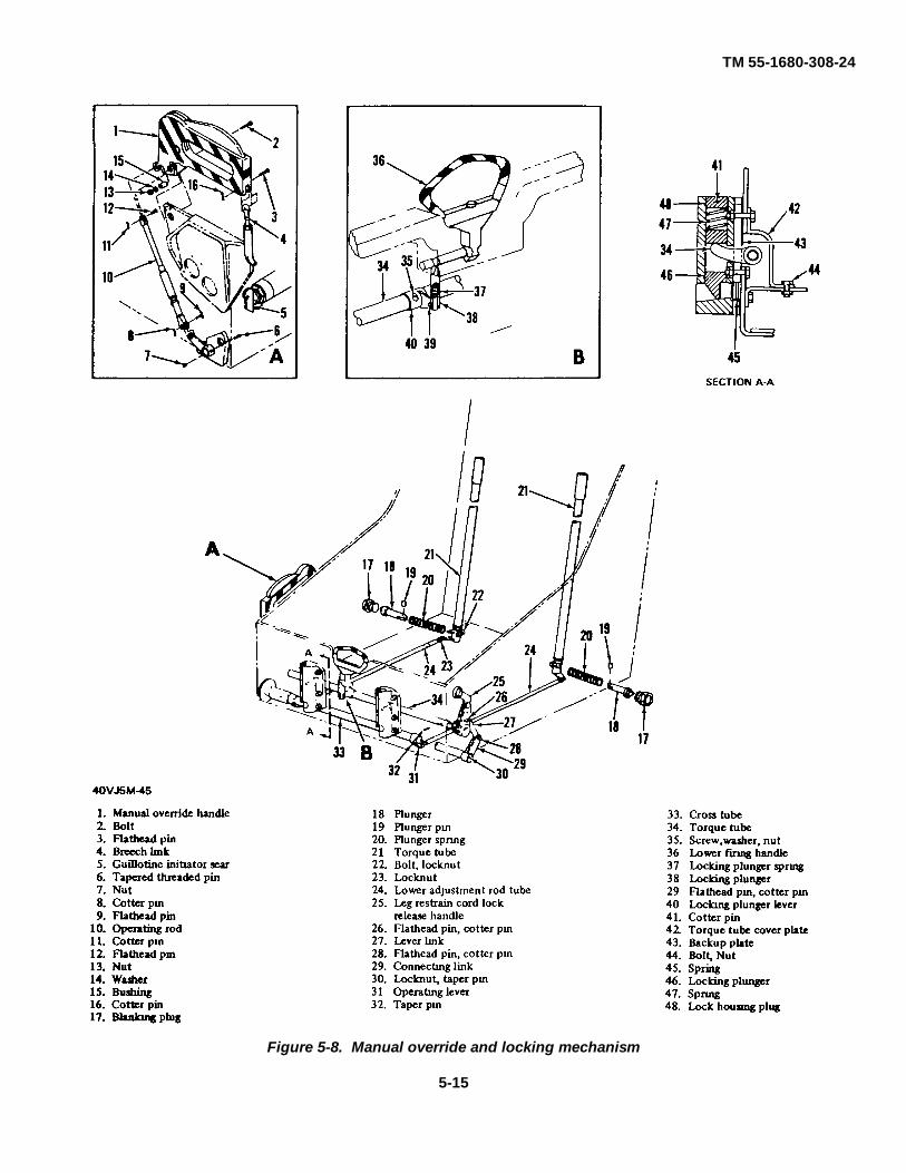
TM 55-1680-308-24
Figure 5-8. Manual override and locking mechanism
5-15
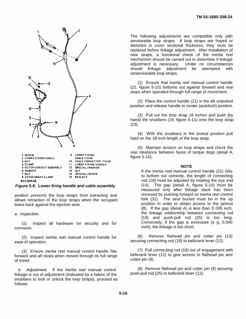
TM 55-1680-308-24
Figure 5-9. Lower firing handle and cable assembly
position prevents the loop straps from extracting andallows retraction of the loop straps when the occupantleans back against the ejection seat.
a. Inspection.
(1) Inspect all hardware for security and forcorrosion.
(2) Inspect inertia reel manual control handle forease of operation.
(3) Ensure inertia reel manual control handle hitsforward and aft stops when moved through its full rangeof travel.
b. Adjustment. If the inertia reel manual controllinkage is out of adjustment (Indicated by a failure of thesnubbers to lock or unlock the loop straps), proceed asfollows:
The following adjustments are compatible only withserviceable loop straps. If loop straps are frayed ordistorted in cross sectional thickness, they must bereplaced before linkage adjustment. After installation ofnew straps, a functional check of the inertia reelmechanism should be carried out to determine if linkageadjustment is necessary. Under no circumstancesshould linkage adjustment be attempted withunserviceable loop straps.
(1) Ensure that inertia reel manual control handle(21, figure 5-10) bottoms out against forward and rearstops when operated through full range of movement.
(2) Place the control handle (21) in the aft unlockedposition and release handle to center (autolock) position.
(3) Pull out the loop strap 18 inches and push (byhand) the snubbers (19, figure 5-11) onto the loop strap(23).
(4) With the snubbers in the locked position pullhard on the 18-inch length of the loop strap.
(5) Maintain tension on loop straps and check therear clearance between faces of torque dogs (detail A,figure 5-10).
NOTEIf the inertia reel manual control handle (21) failsto bottom out correctly, the length of connectingrod (18) must be adjusted by rotating the eye end(14). The gap (detail A, figure 5-10) must bemeasured only after linkage slack has beenremoved by pushing forward on inertia reel controlfork (31). The seat bucket must be in the upposition in order to obtain access to the jamnut(8). If the gap (detail A) is less than 0 005 inch,the linkage relationship between connecting rod(18) and push-pull rod (25) is too long.Conversely, if the gap is excessive (e g, 0.040inch), the linkage is too short.
(6) Remove flathead pin and cotter pin (13)securing connecting rod (18) to bellcrank lever (12).
(7) Pull connecting rod (18) out of engagement withbellcrank lever (12) to give access to flathead pin andcotter pin (9).
(8) Remove flathead pin and cotter pin (9) securingpush-pull rod (25) to bellcrank lever (12).
5-16

TM 55-1680-308-24
Figure 5-10. Inertia reel manual control linkage
5-17

TM 55-1680-308-24
Figure 5-11. Inertia reel mechanism disassembly (Sheet 1 of 2)
5-18

TM 55-1680-308-24
KEY to figure 5-11
1. Bearing 26. Loop strap drum 52. Harness beam subassembly2. Locknut, washer 27. Screw, washer 53. Bolt, washer, locknut3. Support bracket 28. Bearing 54. Mounting bracket4. Plunger bellcrank 29. Mounting bracket 55. Bolt, washer, locknut5. Bolt, washer, locknut 30. Bolt, washer, locknut 56. Plunger housing6. Roller 31. Taper pin 57. Support bracket7. Pivot pin 32. Lever 58. Screw, washer, locknut8. Locking plunger sub- 33. Flathead pin, cotter pin 59. Flathead pin, cotter pin
assembly 34. Link 60. Locknut, washer9. Plunger housing 35. Screw, washer, locknut 61. Bearing10. Mounting bracket 36. Eye end 62. Bolt, washer, locknut11. Bolt, washer, locknut 37. Flathead pin, cotter pin 63. Lever12. Cotter pin 38. Locknut 64. Torsion bar13. Locking sleeve 39. Torsion bar 65. Eye end14. Locking piston 40. Bolt, washer, locknut 66. Locknut15. Pivot pin 41. Lever 67. Fork end16. Taper pin 42. Fork end 68. Flathead pin, cotter pin17. Locking lever 43. Flathead pin, cotter pin 69. Taper pin18. Harness beam assembly 44. Plunger 70. Lever19. Snubber 45. Spring 71. Shaft20. Locknut and taper pin 46. Roller 72. Bearing21. Operating lever 47. Cotter pin, pin 73. Screw, washer, locknut22. Taper pin 48. Insert 74. Spring23. Loop strap 49. Roller 75. Strap retainer24. Parachute restraint strap 50. Cotter pin, pin 76. Screw, washer
spreader assembly 51. Shaft 77. Bearing25. Inertia reel flange
Figure 5-11. Inertia reel mechanism disassembly (Sheet 2 of 2)
(9) Back off jamnut (8) of push-pull rod (25).
(10) Adjust (half a turn at a time) on push-pull rod(25) until the correct clearance on the torque dogs isachieved (detail A).
NOTE
With each half-turn adjustment it will benecessary to connect the push-pull rod(25) and connecting rod (18) to thebellcrank lever (12) with the flathead pinsonly (no cotter pins required during theadjustment phase) in addition theprocedures In (2), (3), (4) and (5) must berepeated with each progressive half turnadjustment. This step-by-step methodmust be carried out until a finaladjustment gives the smallest gap withinthe tolerance of not less than 0.005 inch.
(11) Tighten up jamnut (8) of push-pull rod (25).
(12) Using new cotter pins, assemble linkage asfollows:
(a) Install flathead pin and cotter pin (9) securingpush-pull rod (25) to bellcrank lever (12).
(b) Engage connecting rod (18) into bellcranklever (12).
(c) Install flathead pin and cotter pin (13) securingconnecting rod (18) to bellcrank lever (12).
(13) Carry out a functional check of inertia reelmechanism in accordance with paragraph 4-6t.
(14) For troubleshooting procedures, refer to table5-1.
5-19

TM 55-1680-308-24
Table 5-1. Troubleshooting, DS and GS Maintenance
Malfunction Probable Cause Corrective Action
Loop straps do not release until Lower adjustment rod tubes too long Shorten lower adjustment rod tubes onmanual override handle engages bottom of ejection seat (Refer toaft strap. paragraph 5-18 )
Leg restraint cords release Lower adjustment rod tubes too short Lengthen lower adjustment rod tubesbefore or at the same time on bottom of ejection seat. (Referas seat restraint system to paragraph 5-18.)releases.
Rigid seat restraint lugs Adjustment link on left-hand side If left lug releases first, shortendo not release at the same of main beam and below drogue adjustment link on left side of maintime. gun, out of adjustment beam. If right lug releases first,
lengthen adjustment link on leftside of main beam (Refer to paragraph5-18.)
Leg restraint cord will not Broken spring or worn plunger Replace dual leg restraint cord lock.lock Into leg restraint locks In leg restraint cord lock (Refer to paragraph 5-12.)
Inertia reel manual control Inertial reel linkage too long Adjust inertia reel manual controlhandle falls to unlock loop linkage (Refer to paragraph 5-15b.)straps
No manual lock or autolock for Inertia reel linkage too short Adjust inertia reel manual controlinertia reel manual control linkage. (Refer to paragraph 5-15b )
Loop strap snubber counterweight Inertia reel linkage too short. Lengthen inertia reel manual controldoes not contact counterweight linkage (Refer to paragraph 5-15b )strap
5-16. Inertia Reel Manual Control Handle.
The inertia reel manual control handle is a three-position control located aft of the leg restraint cord lockrelease handle on the left side of the seat bucket. Whenplaced in the spring-loaded autolock position, the inertiareel manual control handle allows the harness loopstraps to extend and retract The forward lock positionallows retraction only.
a. Removal.
(1) Remove bolt, washer, spacer, and nut (20,figure 5-10) and remove cover plate (22) from seatbucket.
(2) Remove flathead pin and cotter pin (19) andbolt, washer, nut (17) attaching inertia reel manualcontrol handle (21) to connecting rod (18) and removehandle.
b. Inspection.
(1) Inspect inertia reel manual control handle fordamage, corrosion, and excessive wear.
(2) Inspect all attaching parts for burrs, damagedthreads, split washers, and cracked or sheared flatheadpin.
c. Repair or Replacement. Repair of the inertia reelmanual control handle consists of replacing defectivecomponents.
d. Installation.
(1) Place inertia reel manual control handle (21,figure 5-10) on end of connecting rod (18) and securehandle with flathead pin and cotter pin (19) and bolt,washer, nut (17).
(2) Install bolt, washer, spacer, and nut (20)securing coverplate (22) to seat bucket.
5-20

TM 55-1680-308-24
5-17. Inertia Reel Mechanism.
The inertia reel mechanism (figure 5-11), locatedunderneath and behind the central support bracket,consists of four major parts: a harness, loop strap (23), asnubber (19), and a dual spring4oaded loop strapretraction reel. The inertia reel mechanism provides ameans of retention for the upper portion of theoccupant's harness. The loop strap, which Is rolled ontoa retraction reel, passes through the snubber andthrough the parachute roller yoke on the personnelparachute. The free end of the loop strap, whichcontains a lug, is then inserted into the harness lock.The snubber prevents forward movements of theoccupant when the occupant exceeds 2 to 3 g's forceparallel to the main beam, or when the inertia reelmanual control handle is in the forward (locked) position.The retraction reel takes up slack in the loop strap whenthe occupant sits back. The occupant cannot leanforward until he places the inertial reel manual controlhandle to the aft (unlocked) position.
a. Removal.
(1) Remove bolt, washer, and nut that secure backplate to head box.
(2) Remove flathead pins and cotter pins (68 and59, figure 5-1 1) that secure fork end (67) and eye end(65) to levers (63 and 70). Separate fork end and eyeend and remove locknut (66).
(3) Remove torsion bar (64) which Is secured bylocknut and washer (60), and remove bearing (61), bolt,washer, and locknut (62), and lever (63).
(4) Remove bolt, washer, and locknut (53), screw,washer and locknut (58), support bracket (57), andmounting bracket (54).
b. Disassembly.
(1) Drift out taper pin (69, figure 5-11) and removelever (70).
(2) Remove bolts, washers, and locknuts (55), andremove plunger housing (56).
(3) Remove flathead pins and cotter pins (43 and37) that secure fork end (42) to plunger bellcrank (4) andeye end (36) to lever (32). Separate fork end from eyeend and remove locknut (38).
(4) Remove bolt, washer, and locknut (30), bearing(77), and plunger bellcrank (4).
(5) Remove link (34) which is secured by flatheadpins and cotter pins (33).
(6) Remove torsion bar (39) which is secured by
locknut and washer (2), and remove bearing (1), bolt,washer, and locknut (40), and lever (41).
(7) Remove bolt, washer, and locknut (5), screw,washer, and locknut (35), support bracket (3), andmounting bracket (10).
(8) Remove lever (32), which is secured to shaft(71) by taper pins (31).
(9) Remove bolts, washers, and locknuts (11) andmounting bracket (29). Remove locking plungersubassembly (8), plunger housing (9), spring (45),plunger (44), and parachute restraint strap spreaderassembly (24). Drift out pivot pin (7) and remove roller(6).
(10) Remove loop strap (23) by removing screwsand washers (76); loosen inertia reel flange (25), rotatesnubber (19) aft and remove flange retaining screw fromflange (25).
(11) Pull loop strap off drum and remove loop strap(23) from loop strap retainer (75) and pull loop strappast snubber (19) Slide inertia reel flange (25) outboardaway from loop strap (23).
(12) Remove loop strap retainer (75) and pull loopstrap (23) past snubber (19).
(13) Remove taper pin (22) and operating lever (21)Remove locknut and taper pin (20) securing snubber(19) to shaft (51). Remove taper pin (16) securinglocking lever (17) to shaft (51) and remove shaft andsnubber.
(14) Remove locking lever (17) and locking piston(14) from locking sleeve (13) Remove spring which ishoused in locking sleeve (13), and separate lockingpiston (14) from locking lever (17) by removing pivot pin(15). Remove locking sleeve (13) by removing cotterpin (12).
(15) Remove rollers (46 and 49), which are securedby cotter pins and pins (47 and 50), and remove insert(48).
(16) Remove screw, washer, and locknut (73),screw and washer (27), inertia reel flange (25) bearings(28 and 72), spring (74), and loop strap drum (26).
c. Cleaning.
(1) Clean all removed components, except the loopstrap, in drycleaning solvent (item 6, table 1-2).
(2) Dry component parts with clean, filtered,compressed air.
5-21
TM 55-1680-308-24
d. Inspection.
(1) Inspect all hardware for stripped threads.
(2) Inspect all mounting brackets and componentsfor elongated mounting holes, cracks, and for brightareas, indicating binding.
(3) Inspect harness release roller for evidence ofwear.
(4) Inspect shafts for defects and evidence of wear.
(5) Inspect loop strap for fraying, broken stitches,and cuts.
NOTEFrayed loop strap edges 1/8-inchmaximum both sides are consideredserviceable.
(6) Inspect plunger spring and torsion spring to seeif they are broken, stretched, or bent.
e. Repair or Replacement.
(1) Replace all taper pins removed duringdisassembly.
(2) Replace any worn, mutilated, or loose fittingbearings.
(3) Replace any springs found to be damaged.
(4) Replace loop strap if cut or if excessivelyfrayed.
f. Lubrication. Apply a light coating of lubricating oil(Item 2, table 1-2) to all moving parts prior toreassembly
g. Reassembly.
(1) Position loop strap drum (26, figure 5-11) andslide spring (74) over shaft (71), then install shaft, andsecure spring on shaft with screw, washer, and locknut(73).
(2) Install bearings (28 and 72) and inertia reelflange (25) on shaft (71).
NOTEDo not secure inertia reel flange (25) toloop strap drum (26) at this time.
(3) Install rollers (46 and 49) and secure with pinsand cotter pins (47 and 50) Install insert (48).
(4) Install operating lever (21) on shaft (51) andsecure with taper pin (22) Position snubber (19) and
install shaft (51), then secure snubber to shaft withlocknut and taper pin (20) Install locking sleeve (13) andsecure with cotter pin (12), then insert spring in lockingpiston (14) and insert locking piston In locking sleeve(13). Position locking lever (17) on shaft (51), thensecure to shaft with taper pin (16), and to locking piston(14) with pivot pin (15).
(5) Insert loop strap (23) under roller (46) andsnubber (19), and over roller (49). Insert strap retainer(75) in end of loop strap (23). Install inertia reel flange(25) and loop strap (23) on strap retainer (75) and slideinertia reel flange (25) out on loop strap drum (26) sothat drum screw hole is visible.
(6) Rotate loop strap drum (26) clockwise (asviewed from the right side) until fully tight, back off one-half turn Holding loop strap drum firmly, insert loop strap(23) with strap retainer (75) In slot in loop strap drum.Release loop strap drum slowly until loop strap is woundon drum.
Holes must align, otherwise, screwssecuring flanges to drum will be sheared.
(7) Slide inertia reel flange (25) m on loop strapdrum (26) until holes align, and secure flange to drumwith screw and washer (76) Secure spring (74) to drumwith screw and washer (27). Install flange retainingscrew.
(8) Insert roller (6) in slot of locking plungersubassembly (8) and secure with pivot pin (7). Insertspring (45), plunger housing (56 and 9), and mountingbracket (29), and secure to harness beam assembly (18)with bolts, washers, and locknuts (55 and 11) Installplunger (44).
(9) Install lever (32) on shaft (71) with taper pins(31).
(10) Install support and mounting brackets (3 and10), and secure with screw, washer, and locknut (35).
(11) Position plunger bellcrank (4), insert bearing(77), and secure with bolt, washer, and locknut (30).
(12) Screw locknut (38) on eye end (36) and screweye end into fork end (42). Position fork end on plungerbellcrank (4) and secure with flathead pin and cotter pin(43). Position eye end on lever (32) and secure withflathead pin and cotter pin (37).
(13) Position lever (41) and insert torsion bar (39)through lever and support bracket (3), then Insertbearing
5-22

TM 55-1680-308-24
(1) and secure torsion bar with washer and locknut (2)and bolt, washer, and locknut (40).
(14) Position link (34) and secure to levers (41 and32) with flathead pins and cotter pins (33).
(15) Install lever (70) on shaft (71) and secure withtaper pin (69).
h. Installation.
(1) Install mounting bracket (54) and supportbracket (57) and secure with bolt, washer, and locknut(53) and screw, washer, and locknut (58).
(2) Position lever (63) and insert torsion bar (64)through lever and support bracket (57), then insertbearing (61) and secure torsion bar with washer andlocknut (60) and bolt, washer, and locknut (62).
(3) Screw locknut (66) on eye end (65) and screweye end in fork end (67). Secure fork end to lever (70)and eye end to lever (63) with flathead pins and cotterpins (68 and 59).
(4) Install bolt, washer, and nut securing backplateto head box.
i. Maintenance Operational Check
(1) Place inertia reel manual control handle (21,figure 5-10) in center (autolock) position.
(2) Pull loop strap out to its extreme position.
(3) Move inertial reel manual control handle toforward (locked) position.
(4) Slowly allow loop strap to retract a few inches ata time, then pull forward on loop strap to see if the loopstrap locks.
(5) Repeat procedure in preceding step (4) untilloop strap is fully retracted.
(6) Move inertia reel manual control handle tocenter (autolock) position and pull on loop strap. Loopstrap should be locked.
(7) Move inertia reel manual control handle to aft(unlocked) position and release handle. Handle shouldmove to center (autolock) position.
NOTEThe inertial reel manual control handle isspring-loaded to the center (autolock)position.
(8) Pull loop strap out to its fully extended positionand release loop strap slowly. Loop strap shouldcompletely retract.
(9) Move inertia reel manual control handle toforward (locked) position and check to see that snubbercontacts loop strap across the entire surface of loopstrap.
(10) Move inertia reel manual control handle to aft(unlocked) position and allow handle to return to center(autolock) position. Ensure snubber hits stop on mainbeam assembly.
(11) Place inertia reel manual control handle to aft(unlocked) position, and withdraw loop strapapproximately 2 feet.
(12) Release Inertia reel manual control handle.
(13) With loop strap partially extended, manuallypress snubber against the loop strap.
(14) Holding tension on loop strap, measuredistance between lever and end stop (See detail A,figure 5-11.) Clearance must be 0.005 inch minimum.
NOTE
Reference paragraph 5-16 for correctiveaction.
5-18 Manual Override System.
The manual override system consists of interlinkedpush rods and torsion rods which actuate the followingcontrols.
a. Control Actuation.
(1) Breech link (4, figure 5-8) withdraws guillotineinitiator sear (5).
(2) Locking plungers (46) lock and unlock the cordfittings (6, figure 1-8).
(3) Locking plunger (38, figure 5-8) locks andunlocks the lower firing handle (36).
(4) Plungers (18) lock and unlock rigid seatretention lugs (7, figure 4-36).
(5) Plunger (44, figure 5-11) locks and unlocks theloop strap lug.
(6) Plunger pin (30, figure 5-2) locks and unlocksthe body of the face blind.
5-23

TM 55-1680-308-24
b. Operational Sequence When the manual overridehandle is moved up and aft, the following actions shouldoccur in sequence:
(1) The guillotine initiator sear should withdraw fromits firing mechanism.
(2) The leg restraint cords should be released at thecord lock fittings first.
(3) The rigid seat lugs should next releasesimultaneously.
(4) The loop strap lug is released last.
(5) Locking of the face blind and lower firing handlemay occur anytime between steps (1) and (4) above.
c. Rigging Standard. With the manual overridehandle (1, figure 5-8) In the forward and down (locked)position, the plungers (18) and plunger (44, figure 5-11)should bottom out against their housings. The end ofthe plungers should touch the housing and there shouldbe no clearance. With the manual override handle inthe up and aft (unlocked) position, the plunger (44)should be withdrawn so that the end of the plunger isrecessed in the housing by at least 1/16 inch Plungers(18, figure 5-8) should recess at least 1-32 inch. Whenmoving the handle from down (locked) to up and aft(unlocked) position, both plungers (18) must withdrawwithin their housings simultaneously.
NOTE
Adjustment to the loop strap lug lockingplunger or side plate locking plungersrequires the personnel parachute, RSSKassembly, and parachute back plate beremoved. In addition, the seat must bemounted horizontally on the seatmaintenance cradle.
d. Loop Strap Locking Plunger Adjustment. If plunger(44, figure 5-11) is out of adjustment or fails to releasethe loop strap lugs properly, proceed as follows:
(1) Place the manual override handle in the forward(locked) position.
(2) Remove cotter pin (10, figure 5-2), washer (11)and clevis pin (12) from plunger assembly (13).Disconnect plunger assembly from plunger bellcrank (4,figure 5-11).
(3) Back off locknut (38) and push down onbellcrank lever in order to adjust fork end (42) untilplunger (44) recesses not less than 1/16 inch in itshousing when manual override handle is moved to aft
(unlocked) position. Check that end of plunger bottomsout on housing body when manual override handle is inforward (locked) position.
NOTE
The fork end (42) must be adjusted 1/2 aturn at a time After each 1/2 turnadjustment, the clevis pin (12, figure 5 2)must connect the fork end (42, figure 5-11) to plunger bellcrank (4). Afterconnecting the fork end to plungerbellcrank, the adjustment related to thelocked and unlocked position of themanual override handle can be checkedon each turn of fork end.
(4) When correct adjustment has been achieved,tighten locknut (38) and assemble In reverse order.
(5) Verify that face blind locking mechanism linkagehas not affected the plunger (44) adjustment whenplunger assembly (13, figure 5-2) is connected to forkend (42, figure 5-11) and plunger bellcrank (4).
e. Rigid Seat Restraint Lug Adjustment. If theplungers (18, figure 5-8) are out of adjustment or fall torelease the side lugs simultaneously, proceed asfollows:
(1) Place the manual override handle in the down(locked) position.
(2) Disconnect lower adjustment rod tubes (24)from torsion tube levers (21).
(3) Remove flathead pin and cotter pin (68, figure5-I1l).
(4) Back off locknut (66).
(5) Adjust fork end (67) by 1/2 turn at a time untilthe plunger (18, figure 5-8) meets the rigging standardestablished above.
NOTE
After each 1/2 turn adjustment of fork end(67, figure 5-1 1), It will be necessary toengage lever (70) to fork end (67) viaflathead pin, cotter pin (68) By this step-by-step method, a check is made onevery 1/2 turn adjustment until the riggingstandard is achieved.
(6) Connect lower adjustment rod tubes (24, figure5-8) to torsion tube levers (21).
5-24

TM 55-1680-308-24
NOTE
The lower adjustment rod tubes (24) mustbe adjusted to conform to the finaladjustment achieved by fork end rod (67,figure 5-11). Any incorrect adjustment oflower tubes (24, figure 5-8) will prevent theplungers (18) from meeting the riggingstandard. Normally, the first indication ofmaladjustment occurs when the plungers(18) fall to move simultaneously.
(7) When correct adjustment has been achieved,tighten locknut (66, figure 5-11) and assemble in reverseorder.
f. Face Blind Locking Mechanism Adjustment. Referto paragraph 5-5h.
NOTE
The face blind and lower firing handles donot have to lock in any given sequence.This function is satisfactory if the twohandles are locked when the manualoverride handle is in the aft (unlocked)position.
If retention points do not release insequence, refer to preceding subparagraphb. If both lap belt halves do not releasesimultaneously, refer to subparagraph d forcorrective action.
5-19. Manual Override Handle.
The manual override handle (1, figure 5-8), located onthe forward right side of the seat bucket, is a two-position handle, locked forward and down, unlocked upand aft. A trigger-type handle grip incorporates aspring-loaded locking mechanism. To actuate themanual override handle, the trigger and handgrip mustbe squeezed and pulled up and aft.
a. Removal.
(1) Remove cotter pin (8, figure 5-8) and flatheadpin (9) securing operating rod (10) to manual overridehandle (1) and separate rod from handle.
(2) Remove cotter pin (16) and flathead pin (3)securing breech link (4) to manual override handle (1)and separate rod from handle
(3) Remove nut (13), washer (14), bushing (15),and bolt (2) securing manual override handle (1) tomounting bracket, and remove handle.
b. Cleaning. Clean all parts with drycleainig solvent(item 6, table 1-2) and dry with a clean cloth or filteredcompressed air.
c. Inspection.
(1) Inspect manual override handle for corrosion,cracks and wear.
(2) Inspect trigger and handgrip for spring tensionand locking operation, free from binding.
(3) Inspect threaded parts for stripped threads.
d. Repair or Replacement Repair of the manualoverride handle consists of replacement of detectivecomponents.
e. Installation.
(1) Position manual override handle (1, figure 5-8)on mounting bracket and secure handle to bracket withbolt (2), bushing (15), washer (14), and nut (13).
(2) Align breech link (4) with manual overridehandle (1) and secure breech link to handle withflathead pin (3) and cotter pin (16).
(3) Align operating rod (10) with manual overridehandle (1) and secure rod to handle with flathead pin (9)and cotter pin (8).
5-20. Emergency Oxygen Bottle Assembly.
The oxygen cylinder (12, figure 5-12) is mounted onthe right side of the seat bucket. The oxygen cylinder isequipped with a valve body assembly and pressuregage (11) and is filled to 1,800 to 2,000 psi with oxygen(Item 7, table 1-2). During high altitude ejection, theoccupant obtains oxygen from the cylinder, enabling himto descend to a safe altitude without the danger of lossof consciousness due to lack of oxygen. Oxygen fromthe emergency oxygen bottle assembly can also beused by the occupant if the aircraft's normal oxygensystem fails during fight. The emergency oxygen bottleassembly consists primarily of an oxygen cylinder, avalve and body assembly and pressure gage, and ahose and connector assembly. The steel, shatterproof,high pressure oxygen cylinder (12) has an internalvolume of 22 5 cubic inches. The oxygen cylinder isattached to the valve body assembly by a threadedconnection. The valve body assembly consists of anoxygen pull cable housing, a pressure gage (II11), and avalve. The pressure gage (11), which shows the oxygenpressure of the oxygen cylinder, has no scalecalibration.
5-25

TM 55-1680-308-24
Figure 5-12. Emergency oxygen bottle assembly-exploded view
except a mark to denote pressure of 1,800 and 2,500psi, and a scale divided into two segments, red andblack. The gage pointer, when positioned in the blacksegment of the arc, indicates that the oxygen cylinder ischarged to at least 1,800 psi If the pointer is in the redsegment, however, the oxygen cylinder content is toolow for safe operation and the cylinder shall berecharged. The pressure gage is attached to the valvebody (10) by a threaded connection. The oxygen pullcable housing (2), attached to the valve by fourcadmium-plated screws and washers (14), is composedof a housing base, pull cable, and a cable link. Thevalve body assembly consists of a valve body (10),which encases a flow restrictor (8), a breakoff nipple (6),a bushing (5), and filling nipple. The flow restrictor (8),consisting of a tubular body into which is secured aceramic plug and a filter, controls the flow of oxygenfrom the oxygen cylinder to the mask. It is calibrated todischarge the cylinder pressure of 1,800 psi sit apredetermined flow rate of from 10 to 12 liters at77°F(25°C) during the first minute, and approximately 1 literduring the tenth minute of flow. Ten minutes isconsidered the maximum flow period for a cylindercharged to 1,800 psi. The brass breakoff nipple (6),consisting of a seat, a flange, and a hollow tip, providesa leaktight seal until thy tip is broken The bushing (5),when tightened, forces the breakoff nipple (6) and theflow restrictor (8) into operating position. When theemergency oxygen system is activated, the ringencircling the rubber hose and nipple is pulled over in itshousing and the end of the nipple Is fractured at themachined undercut, allowing oxygen to flow at fulloperating pressure from the cylinder through the flowrestrictor Oxygen leakage is prevented by the metal-to-metal seat between the flow restrictor and the valvebody. The hose and connector assembly (1) iscomposed of a rubber hose and bayonet connector.
Do not activate cylinder by pulling the pull cable
a. Service Upon Receipt of Oxygen Cylinder. Theoxygen cylinder may be issued with only enough oxygenpressure to prevent atmospheric air from entering thecylinder and causing condensation, corrosion, or rust.The fact that an oxygen cylinder is received empty orwith only a small amount of pressure does notnecessarily mean that the oxygen cylinder is leaking.Before the cylinder can be filled with oxygen, anyoxygen already present in the cylinder must bedischarged and the cylinder purged of all air andmoisture. Purge, service, and leak-test cylinder as soonas oxygen has been discharged from cylinder.
5-26
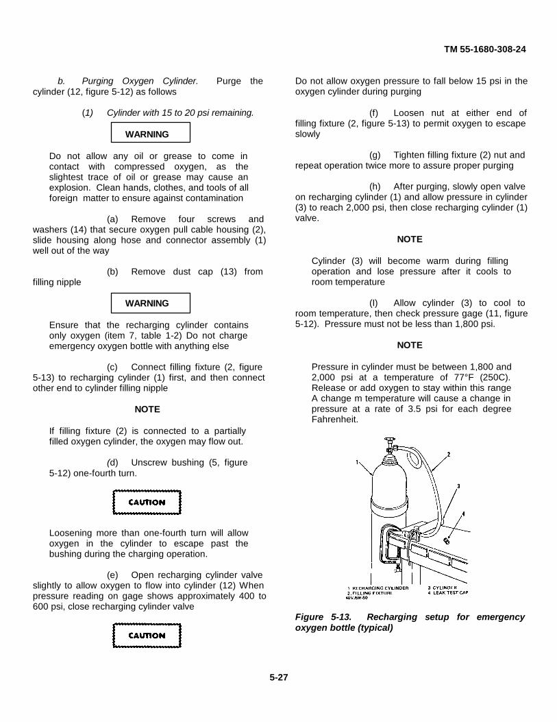
TM 55-1680-308-24
b. Purging Oxygen Cylinder. Purge thecylinder (12, figure 5-12) as follows
(1) Cylinder with 15 to 20 psi remaining.
WARNING
Do not allow any oil or grease to come incontact with compressed oxygen, as theslightest trace of oil or grease may cause anexplosion. Clean hands, clothes, and tools of allforeign matter to ensure against contamination
(a) Remove four screws andwashers (14) that secure oxygen pull cable housing (2),slide housing along hose and connector assembly (1)well out of the way
(b) Remove dust cap (13) fromfilling nipple
WARNING
Ensure that the recharging cylinder containsonly oxygen (item 7, table 1-2) Do not chargeemergency oxygen bottle with anything else
(c) Connect filling fixture (2, figure5-13) to recharging cylinder (1) first, and then connectother end to cylinder filling nipple
NOTE
If filling fixture (2) is connected to a partiallyfilled oxygen cylinder, the oxygen may flow out.
(d) Unscrew bushing (5, figure5-12) one-fourth turn.
Loosening more than one-fourth turn will allowoxygen in the cylinder to escape past thebushing during the charging operation.
(e) Open recharging cylinder valveslightly to allow oxygen to flow into cylinder (12) Whenpressure reading on gage shows approximately 400 to600 psi, close recharging cylinder valve
Do not allow oxygen pressure to fall below 15 psi in theoxygen cylinder during purging
(f) Loosen nut at either end offilling fixture (2, figure 5-13) to permit oxygen to escapeslowly
(g) Tighten filling fixture (2) nut andrepeat operation twice more to assure proper purging
(h) After purging, slowly open valveon recharging cylinder (1) and allow pressure in cylinder(3) to reach 2,000 psi, then close recharging cylinder (1)valve.
NOTE
Cylinder (3) will become warm during fillingoperation and lose pressure after it cools toroom temperature
(I) Allow cylinder (3) to cool toroom temperature, then check pressure gage (11, figure5-12). Pressure must not be less than 1,800 psi.
NOTE
Pressure in cylinder must be between 1,800 and2,000 psi at a temperature of 77°F (250C).Release or add oxygen to stay within this rangeA change m temperature will cause a change inpressure at a rate of 3.5 psi for each degreeFahrenheit.
Figure 5-13. Recharging setup for emergencyoxygen bottle (typical)
5-27

TM 55-1680-308-24
(j) Tighten bushing (5) to a torqueof 180 inch-pounds.
(k) Unscrew filling fixture (2, figure5-13) from cylinder and replace with leak-test cap (4),Part No212A31
(l) Leak-test cylinder (Refer tosubparagraph d)
(2) Cylinder with less than 15 psiremaining.
WARNING
Do not allow any oil or grease to come mcontact with compressed oxygen, as theslightest trace of oil or grease may cause anexplosion Clean hands, clothes, and tools of allforeign matter to ensure against contamination.
(a) Loosen cylinder valve bodyassembly and allow any trapped oxygen to escape.
Do not place cylinder in a vise unless protectedby wooden blocks or equivalent. Damage to thecylinder walls Is cause for rejection.
(b) Remove valve body assemblyfrom cylinder (12, figure 5-12).
(c) Inspect inside of cylinder (12)for moisture accumulation and rust.
NOTE
Any evidence of rust Is cause for rejection ofcylinder (12).
(d) Connect filling fixture (2, figure5-13) to recharging cylinder (1) and blow out inside ofoxygen cylinder.
WARNING
Ensure that the recharging cylinder contains onlyoxygen (item 7, table 1-2) Do not recharge oxygencylinder with anything else.
(e) Install valve body assembly intocylinder.
(f) Remove four screws and fourwashers (14, figure 5-12) and washers that secureoxygen pull cable housing (2), slide housing along hoseand connector assembly (1) well out of the way
(g) Remove dust cap (13) fromfilling nipple
NOTE
If filling fixture (2) is connected to a partiallyfilled cylinder, the oxygen may flow out.
(h) Connect filling fixture (2, figure5-13) to recharging cylinder (1) first and then connectother end to cylinder filling nipple.
NOTE
Loosening bushing more than one-fourth turnwill allow oxygen in the cylinder to escape pastthe bushing during the recharging operation.
(i) Unscrew bushing (5, figure 5-12) one-fourth turn.
(j) Open recharging cylinder valveslightly to allow oxygen to flow Into cylinder (3, figure 5-13) When pressure reading on pressure gage showsapproximately 400 to 600 psi, close recharging cylindervalve.
Do not allow oxygen pressure to fall below 15psi in the cylinder during purging.
(k) Loosen nut at either end offilling fixture (2) to permit oxygen to escape slowly.
(1) Tighten recharging cylinder nut andrepeat operation twice more to assure proper purging.
(m) After purging, slowly openrecharging cylinder and allow pressure in cylinder toreach 2,000 psi; then close recharging cylinder valve.
NOTECylinder will become warm during filling operation andwill lose pressure after it cools to room temperature.
(n) Allow cylinder (3) to cool toroom temperature, then check pressure gage (11, figure5-12). Pressure must not be less than 1,800 psi.
5-28
TM 55-1680-308-24
NOTE
Pressure in cylinder must be between 1,800 and2,000 psi at the temperature of 77°F (250C)Release or add oxygen to stay within this rangeA change in temperature will cause a change inpressure at a rate of 3.5 psi for each degreeFahrenheit.
(o) Tighten bushing (5) to a torqueof 180 Inch-pounds.
(p) Unscrew filling fixture (2, figure5-13) from cylinder and replace with leak-test cap (4),Part No. 212A31.
(q) Leak-test cylinder (Refer tosubparagraph d).
c. Servicing. If the pressure gage (11, figure5-12) shows an oxygen pressure of more than 20 psi butless than 1,800 psi, proceed as follows.
NOTE
The cylinder must be purged If oxygen pressureis 20 psi or less.
(1) Remove screws and washer (14) fromvalve body (10), and slide pull cable housing (2) andattached parts along hose and connector assembly (1)well out of the way.
WARNING
Do not allow any oil or grease to come incontact with compressed oxygen, as theslightest trace of oil or grease may cause anexplosion Clean hands, clothes, and tools of allforeign matter to ensure against contamination.
(2) Remove dust cap (13) from fillingnipple on valve body (10).
WARNING
Ensure that the recharging cylinder containsonly oxygen (item 7, table 1-2). Do not chargeemergency oxygen cylinder with anything else.
NOTE
If filling fixture is connected to a partially filledcylinder, the oxygen may flow out.
(3) Connect filling fixture (2, figure 5-13)
to recharging cylinder (1) first, and then connect otherend to cylinder breakoff nipple (6, figure 5-12).
Loosening bushing more than one-fourth turnwill allow oxygen in the cylinder to escape pastthe bushing during the charging operation.
(4) Unscrew bushing (5) one-fourth turn.
(5) Slowly, open valve on rechargingcylinder (1, figure 5-13) and allow pressure in oxygencylinder to reach 2,000 psi, then close rechargingcylinder valve.
NOTE
Oxygen cylinder will become warm during fillingoperation and will lose pressure after it cools toroom temperature.
(6) Allow cylinder, (3) to cool to roomtemperature, then check pressure gage (11, figure 5-12). Pressure must not be less than 1,800 psi.
NOTE
Pressure m cylinder must be between 1,800 and2,000 psi at a temperature of 77°F (250C)Release or add oxygen to stay within this rangeA change m temperature will cause a change inpressure at a rate of 3 5 psi for each degreeFahrenheit.
(7) Tighten bushing (5, figure 5-12) to atorque of 180 inch-pounds.
(8) Unscrew filling fixture (2, figure 5-13)from cylinder and replace with leak-test cap (4), Part No.212A31.
(9) Leak-test the oxygen cylinder (Referto following subparagraph d).
d. Leak-Testing Cylinder.
(1) Using a mild, water mixed solution ofdetergent (hand-dlshwashing compound), check forleaks between valve body (10, figure 5-12) and cylinder(12), valve body (10) and pressure gage (11) and atleak-test cap (4, figure 5-13) bleed hole.
(2) Carefully tighten componentssuspected of contributing to observed leakage, andrepeat preceding step (1).
5-29

TM 55-1680-308-24
NOTE
If leaks cannot be eliminated by tightening orreplacing parts, replace with a serviceableemergency oxygen bottle assembly.
(3) If leakage is still detected, replacesuspected defective parts and repeat preceding step (1).
e. Inspection.
(1) Check that pressure gage (11, figure5-12) reads at least 1,800 psi at an ambient temperatureof 77°F (25°C) A change In. temperature will cause achange in pressure at a rate of 3.5 psi for each degreeFahrenheit.
NOTE
If the pressure gage reads zero psi, this Is anindication that a leak exists or that the breakoffnipple (6) is ruptured.
(2) Inspect pressure gage (11) forcracked or broken cover glass, dents, or other visibledefects.
(3) Inspect pull cable housing (2) fordeformity and interference with or binding on pull cable.
(4) Inspect shear rivet in cable link forsigns of shearing.
(5) Inspect hose for cuts, breaks, ordeterioration, and for proper connection to bayonetconnector
(6) Inspect oxygen hose quick-disconnectbridle and lanyard for cracks and deformation.
f. Repair or Replacement. Replace all itemsfound defective during inspection.
(1) Replace pull cable housing (2, figure5-12) if pull cable, or pull cable housing rivets showsigns of damage.
(2) If cable link shear rivet shows signs ofshearing or has been sheared, replace rivet as follows:
Use exterior caution when removing anunserviceable rivet to avoid enlarging the hole.
(a) Clear holes in cable link thatcontain unserviceable rivet parts.
WARNING
To ensure proper shearing characteristics onejection, use rivet, Part No MS20470A2-6, only.Incorrect rivet may cause malfunction ofemergency oxygen system.
(b) Align lower link in upper linkand position spacer In lower link. Insert shear rivetthrough link and spacer, assuring that rivet head facesright side of aircraft .
Avoid using unnecessary force on links whenbucking to prevent distorting links and rivet.
(c) Buck rivet using a small, thickbucking bar.
(3) If oxygen cylinder is partially filled(less than 1800 psi), proceed as follows.
(a) Service oxygen cylinder (Referto subparagraph c ).
(b) Leak-test oxygen cylinder(Refer to subparagraph d ).
(4) If hose and connector assembly (1,figure 5-12) requires replacement, proceed as follows.
(a) Remove screws and washers(14) from valve body (10), and slide pull cable assembly(3) and attached parts along hose and connectorassembly (1) well out of the way.
(b) Loosen bushing (5) enough topermit oxygen to start escaping As cylinder pressure isgradually reduced, bushing may need to be loosenedapproximately one and one-half turns to allow all oxygento escape from cylinder.
(c) Remove breakoff nipple (6)from hose and connector assembly (1).
(d) Replace O-ring (7).
(e) Insert breakoff nipple (6) intonew hose and connector assembly (1) and work it inuntil flanged face seats firmly against hose end.
(f) Holding hose and connectorassembly (1), work bushing (5) down until it seats firmlyagainst face of breakoff nipple (6).
5-30

TM 55-1680-308-24
Ensure that parts do not fall on floor or comein contact with any foreign matter wheninverting cylinder.
(g) Invert cylinder (12) so that flowrestrictor (8) and spring (9) drop out of valve body (10).
Use only oxygen (item 7, table 1-2) to blow outvalve body Do not use compressed air.
(h) Inspect interior of valve body(10) for foreign matter If necessary, blow clean, usingoxygen (item 7, table 1-2).
(i) Insert spring (9) and flowrestrictor (8) into valve body (10).
(j) Check that flange of breakoffnipple (6) is properly seated against bushing (5) Screwbushing Into valve body (10) only enough to snug upparts Do not tighten beyond a snug fit.
(k) Purge oxygen cylinder. (Referto subparagraph b).
(l) Service oxygen cylinder(Refer to subparagraph c ).
(m) Tighten bushing (5) to a torqueof 180 inch-pounds.
(n) Leak-test oxygen cylinder(Refer to subparagraph d.)
(o) Slide pull cable housing (2)down hose and connector assembly (1), over top ofvalve body, and secure with screws and washer (14).
5-21. Emergency Oxygen System Linkage.An actuating cable from the oxygen cylinder is
attached by three links, a 1/16-inch aluminum shearrivet, flathead pin, washer and cotter pm, and a quick-release pin to a bellcrank mounted below the oxygencylinder The ejection gun trip rod crossbeam mountedon the ejection gun barrel holds a quick-release typestriker pin (the same quick-release pin that secures thetime release mechanism trip rod to the ejection gun triprod crossbeam} As the seat rises during ejection, a triplever is deflected downward when it comes in contactwith the quick release sticker pin and transmits thedeflection to the bellcrank, pulling on the oxygencylinder cable, fracturing a breakoff nipple within theoxygen cylinder, and releasing the oxygen supply (Since
only a 1/4-inch pull on the cable is required to actuatethe oxygen cylinder, and the cable deflection is notenough to allow the bellcrank and trip lever to clear thestriker pin, the 1/16inch aluminum rivet securing the twolinks shears ) This permits the trip lever and bellcrank tobe deflected further downward, unrestricted by thelimitations of the oxygen cylinder cable A manuallyactuated knob, located on the upper right side of theseat bucket, is connected by a cable to the bellcrankThe knob provides for manual actuation of the oxygencylinder in case of malfunction in the normal oxygensystem Pulling the manual actuating knob deflects thebellcrank downward, pulls the oxygen actuating cable,fracturing a breakoff nipple within the oxygen cylinder,and releasing the emergency oxygen supply.
a. Removal.
(1) Disconnect oxygen linkage fromoxygen cylinder by removing quick-release pin (25,figure 1-9) that secures cable link (29) to bellcrank (24).
(2) Separate fork end of cable (9) frombellcrank (24) by removing cotter pin (27) and flatheadpin (26).
(3) Separate manual actuating knob (2)from cable (9) by removing nut and washer.
(4) Remove screws and nuts securingcable clamps (8) to seat bucket Remove cable clampsfrom cable conduit (7).
(5) Remove nuts securing actuating knobsupport bracket (3) to seat bucket and remove cable (9).
(6) Remove upper slotted nut and washer(21), using screwdriver, Part No 105GT1044 Removechain of quick-release pin (25) from bellcrank supportbracket (22).
(7) Using screwdriver, Part No105GT1044, remove remaining slotted nuts securingbellcrank support bracket (22) to seat bucket andcarefully slide bracket off shaft (23).
(8) Remove shaft (23) by carefully pullingout on bellcrank (24) As the shaft slides out of trip leverguard (18), the trip lever (30) will fall out.
(9) Remove spring (19) from shaft (23)Separate bellcrank (24) from shaft (23) by drifting outtaper pin (20).
b. Inspection.
(1) Inspect threaded areas for crossed,stripped, or worn threads.
Change 8 5-31

TM 55-1680-30824
(2) Inspect all metal parts for generalcondition.
(3) Inspect cable for fraying, corrosion,and kinks.
c. Repair or Replacement. Replace all partsfound to be defective during inspection.
d. Installation.
(1) Position bellcrank (24, figure 1-9) onshaft (23) and secure bellcrank to shaft with taper pin(20).
(2) Place spring (19) over shaft (23).
(3) Position trip lever (30) In a horizontalposition in trip lever guard (18) Slide shaft (23) into triplever guard and through trip lever so that trip lever willbe In a horizontal position and rest on the flats of theshaft The bellcrank (24) must also be in a horizontalposition relative to the trip lever (See detail A, figure 1-9).
(4) Slide bellcrank support bracket (22)on shaft (23) Position bracket on studs and securebellcrank to lower stud with washer and slotted nut Usescrewdriver, Part No 105GT1044, to Install slotted nut.
(5) Position chain of quick-release pin(25) on upper stud and secure chain and bracket withslotted nut and washer (21) Use screwdriver, Part No105GT1044, to install slotted nut.
(6) Install cable (9) and secure bypositioning actuating knob support bracket (3) on seatbucket and securing with nuts.
(7) Position manual actuating knob (2) oncable (9) and secure with washer and nut.
(8) Secure cable conduit (7) to seatbucket with cable clamps (8), screws, and nuts.
(9) Secure terminal end of cable (9) tobellcrank (24) with flathead pin (26) and cotter pin (27).
(10) Secure cable link (29) to bellcrank(24) with quick-release pin (25).
e. Functional Check. Perform a functionalcheck on the emergency oxygen system as described inparagraph 4-6x.
The quick release type striker pin has a knurledhead The quick release pin is longer than otherpins so it will strike the trip lever.
5-22. Seat Actuating Jack Mechanism.The seat actuating jack mechanism provides for
height adjustment of the seat bucket The seat actuatingjack (figure 5-14) is located in back of the seat bucket,between the vertical beams The shaft end of theactuating jack is bolted to the 40 g crossmember andthe motor end is attached to the seat bucket Amomentary, three-position toggle switch, located on theright side of the seat bucket, sends 28 volts dc from theaircraft electrical system to the actuating jack motorDepending on the position of the toggle switch, the seatbucket will raise or lower to the desired position, througha distance of 4.7 inches of travel.
a. Removal.
(1) Remove connector (8, figure 3-6)from seat raising actuator (7).
(2) Remove bolts, washers, and locknuts(1 and 6) and remove seat actuating jack from ejectionseat.
(3) Remove bolt, washer, and nutsecuring clamp (4) to seat bucket Remove clamp fromelectrical clamp (11).
(4) Remove seat height adjustmentswitch (2), insulating plate, and spacer plate from seatbucket by removing bolts, washers, and locknuts (3).
(5) Disconnect cable leads from seatheight adjustment switch and remove electrical cable(11).
b. Disassembly.
(1) Remove nuts (1, figure 5-15) washers(2), and bolts (3) and separate assembled plate (4), gearhousing (11), and motor (12) as an assembly frombearing housing.
(2) Remove bearing (5), plate (4), gear(6), bearings (7 and 8), gear (9), bearing (10), and gearhousing (II) from motor (12).
(3) Remove nuts (13), washers(14), andbolts(15) and separate bearing housing (22), bearings(16 and 18), and ring gear (17) as an assembly fromjack housing (25) Remove bearing (16), ring gear (17),and bearing(18) from bearing housing (22).
(4) Remove bearing (19), Jackscrew(20), bearing (21), and plug assembly (26) from Jackhousing (25).
(5) Remove screws (23) and connector(24) from jack housing (25).
Change 8 5-32.

TM 55-1680-308-24
c. Cleaning. Clean all parts with dry cleaningsolvent (item 6, table 1-2) and dry with a clean cloth orfiltered, compressed air.
d. Inspection.
(1) Inspect gears for cracks andexcessive wear.
Change 8 5-32.1/(5-32.2 blank)

TM 55-1680-308-24
Figure 5-14. Location of seat actuating jack
5-33

TM 55-1680-308-24
(2) Inspect bearings for galling, excessivewear, and for looseness with mating parts.
(3) Inspect housings for cracks.
(4) Inspect all threaded parts for strippedthreads.
e. Repair or Replacement. Repair of the seatactuating jack mechanism is limited to the replacementof defective components.
f. Reassembly.
(1) Secure connector (24, figure 5-15) tojack housing (25) with screws (23).
(2) Install plug assembly (22), bearing(19), jackscrew (20), and bearing (21) in jack housing(25).
(3) Install bearing (18), ring gear (17),and bearing (16) in bearing housing (22). Secure bear-ing housing to jack housing (25) with bolts (15), washers(14), and nuts (13).
(4) Install gear housing (11), bearing (10),gear (9), bearings (8 and 7), gear (6), bearing (5), andplate (4) on motor (12).
(5) Secure motor (12), gear housing (11),and plate (4) to bearing housing (22) with bolts (3),washers (2), and nuts (1).
g. Installation.
(1) Connect leads of electrical cable (11,figure 3-6) to seat height adjustment switch (2).
(2) Secure spacer plate, insulating plate,and seat height adjustment switch (2) to seat bucket withbolts, washers, and locknuts (3).
(3) Install clamp (4) on electrical cable(11) and secure clamp to seat bucket with bolt, washer,and nut.
(4) Secure seat actuating jack to ejectionseat with bolts, washers, and locknuts (1 and 6).
(5) Install connector (8) to seat raisingactuator (7).
h. Maintenance Operational Check.
(1) Apply 28 volts dc power (20 amperesminimum) to seat actuating jack mechanism.
CAUTION
Do not operate the seat raising actuator morethan 1 minute (maximum) during any 8-minuteperiod of time Extended operation will shortenthe seat raising actuator service life.
(2) Check that seat bucket moves upwhen seat height adjustment switch is pushed aft, andstops when switch is released.
(3) Check that seat jack motor stopswhen seat bucket reaches full up position.
(4) Check that seat bucket moves downwhen seat height adjustment switch is pushed forward,and stops when switch is released.
(5) Check that seat jack motor stopswhen seat bucket reaches full down position.
5-23. Time Release Mechanism.The time release mechanism, mounted on the
upper portion of the right main beam, provides a meanswhereby the occupant will be automatically releasedfrom the ejection seat between ground level and 15,500feet maximum. The time release mechanism isactuated by a trip rod attached to the ejection gun triprod crossbeam by a quick-release pin which pulls thetime release mechanism sear when the ejection seat isejected When 1 65 to 1 85 seconds have elapsed afterthe sear is pulled, the following items will beautomatically released harness loop strap attachment,personnel parachute restraint straps, two rigid seatsurvival kit restraint lugs attached to the seat bucket, legrestraint cord attachment, and the scissor-restraineddrogue shackle A barostatic control incorporated in thetime release mechanism prevents the timingmechanism from operating until the ejection seat hasdescended to a pre set altitude of 15,500 to 14,000 feetoptimum
a. Removal.
(1) Ensure the time release mechanism iscocked.
WARNING
Keep hands clear of area below time releasemechanism plungers. Plungers extend withgreat force.
.
Change 2 5-34

TM 55-1680-308-24
Figure 5-15. Seat actuating jack mechanism - exploded view
5-35

TM 55-1680-308-24
(2) Disconnect bungee from time releasemechanism trip rod (2, figure 4-7).
(3) Carefully support time releasemechanism and remove three mounting bolts.
(4) Slide time release mechanism downwhile turning it outward, or: 1y as much as necessary,until upper plunger rod is clear of guard and guide tubes.
CAUTION
Use caution when removing time release mechanism toprevent bending the upper plunger rod In the scissorrelease plunger housing.
b. Cleaning. Clean time release mechanismusing :. clean cloth slightly moistened with drycleaning,solvent (item 6, table 1-2). Remove all traces of drysolvent using a clean, dry cloth.
c. Inspection.
(1) Inspect time release mechanism forloose or missing hardware.
(2) Inspect time release mechanism forcracks and corrosion.
(3) Ensure cotter pin properly retainscoverplate on side of time release mechanism.
(4) Ensure serrated capsule housing capis properly secured with lockwire.
d. Test.
(1) Perform a time delay operationalcheck in accordance with paragraph 4-6l(1).
(2) Test time release mechanism maccordance with paragraph 4-6l(2).
(3) Perform a standard barostatoperational check in accordance with paragraphs 4-6l(3)or 4-6 l (4), as applicable
e. Barostat Replacement.
(1) Cut lockwire securing barostat to timerelease housing
CAUTIONDo not allow foreign materials to contaminateinternal time release mechanism gears. Do notadd lubricant to internal mechanisms.
(2) Remove barostat assembly.
(3) Install new barostat assemblyhandtight.
(4) Perform barostat operational check inaccordance with paragraphs 4-6l(3) or 4-6l(4), asapplicable.
(5) Lockwire serviceable barostat.
f. Installation. (See figure 4-35.)
(1) Ensure serviceable time releasemechanism is being installed on ejection seat.
NOTEDo not install If overage (refer to para 4- 8).
(2) If a replacement time releasemechanism is to be installed, check that lockwire onbarostat assembly is in proper condition beforeinstallation.
(3) Ensure time release mechanism iscocked.
(4) Remove slack from harness releaseplunger rod by carefully depressing rod until it bottomsout.
(5) Insert harness release plunger rodinto guard and guide tube on ejection seat. Slide timerelease mechanism upward, being careful not to bendthe harness release plunger rod.
WARNING
Keep hands clear of area below time releasemechanism plungers. Plungers extend withgreat force.
(6) Carefully support time releasemechanism and install three mounting bolts.
(7) Connect bungee to time releasemechanism trip rod (2, figure 4-7).
g. Maintenance Operational Check.
(1) Cock time release mechanism inaccordance with paragraph 4-6ad(10).
Change 2 5-36

TM 55-1680-308-24
(2) Functionally check time releasemechanism in accordance with paragraph 4-6ad.
h. Standard Barostat Adjustment.
(1) The following applies when using theVacuum Test Box (TDO 1153).
(a) Remove barostat cap frombarostat assembly.
NOTEThe lock wire securing the barostat to the timerelease mechanism body should not beremoved.
(b) Loosen nut which secures theclamp to the capsule stack adjustment screw.
NOTE
Loosen the nut sufficiently to enable the capsulestack to be turned with a well fitting screwdriver.If too loose, large test variations will occur as aresult of subsequent lock nut tightening afteraltitude adjustment.
(c) With lock nut loosened, inserttime release mechanism into vacuum test box withbarostat cap removed.
Exercise care whenever the barostat cap isremoved to preclude liquid contamination ofexposed surfaces.
(d) Evacuate the vacuum chamberto the prescribed altitude. Refer to paragraph 4-6l(4).
NOTEIf a new barostat is being adjusted, accomplishthree altitude checks to establish initial settingbefore attempting adjustment.
(e) While viewing through thechamber lid, carefully insert adjustment screwdriver intothe slot in the barostat adjustment screw.
(f) If initial test altitude readingswere too high (15,000 to 15,500 feet), turn theadjustment knob clockwise to DECREASE altituderelease point; turn counter clockwise to retract orINCREASE altitude release point.
NOTEA one-eighth turn of the adjustment screw willalter release altitude approximately 700 feet.
(g) Accomplish altitude tests andcontinue adjustment as necessary until desired releasealtitude is attained.
NOTETightening the barostat adjustment screwclamping nut after testing will decrease thealtitude approximately 500 feet Therefore thisafter-test change should be considered whenadjustments are being made.
(h) Repeat altitude test two additionaltimes to confirm release altitude.
(i) Remove time release mechanismfrom vacuum chamber and tighten adjustment screwlock nut and install cap finger tight.
(j) Repeat altitude test three additionaltimes after tightening lock nut to confirm finaladjustment.
(k) Remove time release mechanismfrom vacuum chamber, tighten barostat cap and safetywire.
(2) The following applies when using thebarostat adapter assembly (105GT1030) with externalvacuum motor.
Do not remove lock wire securing barostat totime release mechanism body until afterbarostat cap has been loosened.
(a) Remove lock wire from barostatcap and loosen cap. Remove lock wire securingbarostat to time release mechanism body.
NOTESafety wire must be removed from barostat andtime release mechanism body to assure good fitof vacuum test cup to body face.
(b) Remove barostat cap andloosen nut which secures clamp to the capsule stackadjustment screw.
NOTELoosen the nut sufficiently to enable the capsulestack to be turned with a well fitting screwdriver.If too loose, large variations will occur as aresult of subsequent lock nut tightening afteraltitude adjustment.
Change 2 5-37

TM 55-1680-308-24
NOTE
If a new barostat is being adjusted, accomplishthree altitude checks to establish initial settingbefore attempting adjustment.
(c) If initial test altitude readings were toohigh (15,000 to 15,500 feet), insert well-fittingscrewdriver into adjusting screw slot and turn clockwiseto DECREASE altitude release point; turn counterclockwise to retract or INCREASE altitude release point.
NOTEA one-eighth turn of the adjustment screw willalter release altitude approximately 700 feet.
(d) Install barostat adapter cup overbarostat and begin vacuum testing Refer to paragraph4-61(3).
Exercise care whenever the barostat cap isremoved to preclude liquid contamination ofexposed surfaces.
(e) Accomplish altitude tests andcontinue adjustment as necessary until desired releasealtitude is attained.
NOTETightening the barostat adjustment screw clampnut after testing will decrease the altitudeapproximately 500 feet. Therefore this after-testchange should be considered when adjustmentsare being made.
(f) Repeat altitude test twoadditional times to confirm release altitude.
(g) Remove barostat adapter cup,tighten adjustment screw clamp nut and install barostatcap finger tight.
(h) Repeat altitude test threeadditional times after tightening lock nut to confirm thefinal adjustment.
(i) Lock wire barostat cap andbarostat.
5-24. Guillotine System.The guillotine system provides a method of
cutting the withdrawal line and separating the personnelparachute from the drogue system. Operation of themanual override handle causes a cartridge to be firedGas pressure produced by the exploding cartridgeactuates the guillotine blade which severs the
withdrawal line. The guillotine system consists of thefollowing components interconnecting link- age andoperating levers to the manual override system, breechassembly, flex lines and piping, and the guillotine bladeassembly.
Before attempting to disarm the guillotinebreech assembly, install ground safety lockstreamer assembly, Part No. 134SEME10053,into firing pin sear. With safety pin installed infiring pin sear of the guillotine firing mechanism,push the sear upward as far as possible andremove manual override link rod. Removelockwire from breech assembly and tab washeron seat bucket Carefully unscrew the breechhousing Use extreme caution when removingand handling cartridge, since cartridge has apercussion-type pressure cap. Removeguillotine cartridge from breech assembly.
NOTEFor handling of cartridge, refer to TM 9-1300-206.
a. Removal.
(1) Remove thigh supports from leadingedge of ejection seat (Refer to paragraph 5-30a).
(2) Disconnect link assembly (19, figure5-16) from manual override handle (17) by removingcotter pin (16) and flathead pin (18).
(3) Disconnect lower pipe assembly (6)from initiator housing (20) at nut fitting (22).
(4) Remove nuts (24), washers (23), andbolts (21) securing initiator housing (20) and removeinitiator housing.
(5) Remove nuts (25), washers (26), andbolts (28) from clamps (27) securing lower pipeassembly (6). Remove clamps.
(6) Remove nuts (5) and washers (4)from plate (3) over lower pipe assembly (6) and removeplate.
(7) Disconnect lower pipe assembly (6)from hose assembly (1) at nut fitting (2) and removelower pipe assembly (6).
(8) Disconnect hose assembly (1) fromguillotine assembly (10) at nut fitting (11).
Change 5 5-38

TM 55-1680-308-24
(9) Remove nuts (9), washers (8), andbolts (7) securing guillotine assembly (10) to seat andremove guillotine.
(10) Remove nuts (15), washers (14), andbolts (13) securing clamps (12) and hose assembly (1).Remove clamps and hose assembly.
b. Cleaning.
(1) Clean all removed components in drycleaning solvent (item 6, table 1-2).
(2) Dry components with clean, filtered,compressed air.
c. Inspection.
(1) Inspect all hardware for stripped
threads.
(2) Inspect interconnecting linkage andoperating levers for cracks, corrosion, distortion,elongated holes, and for bright areas indicating binding.
(3) Inspect linkage rod ends and all cotterpins for security.
(4) Inspect cartridge breech assembly fordamage or deterioration.
(5) Inspect guillotine blade assembly forscoring, gouges, cracks, and cleanliness.
d. Repair or Replacement.
(1) Replace all tapered pins removedduring disassembly.
Change 2 5-38A

TM 55-1680-308-24
Figure 5-16. Guillotine system
Change 2 5-38B
TM 55-1680-308-24
(2) Replace any worn, distorted, ormutilated operating levers and interconnecting linkage.
(3) Replace any component founddefective during inspection.
e. Lubrication.
(1) Apply lubricating grease (item 5, table1-2) to all working parts of the guillotine system duringassembly.
(2) Apply a light coat of lubricating oil(item 2, table 1-2) to interconnecting linkage andoperating levers.
f. Installation
WARNING
Use extreme caution when handling andinstalling guillotine cartridge into breechhousing, as cartridge has a percussion-typepressure cap Ensure that firing pin does notprotrude above bottom surface of firing bodyhole. A physical check is required.
Install ground safety lock streamer assembly,Part No 134SEME10053, into firing pin searWith safety pin installed in firing pin sear of theguillotine firing mechanism, push the searupward as far as possible and install manualoverride Ink rod.
Carefully screw In the breech assembly Safety-wire breech assembly to tab washer on seatbucket.
NOTE
Check spring balance on safety guard. Adisturbing load of 6 to 8 pounds must beobtained.
(1) Install and secure guillotine assembly(10, figure 5-16) with bolts (7), washers (8), and nuts (9).
(2) Install initiator housing (20) andsecure with bolts (21), washers (23), and nuts (24).
(3) Swing link assembly (19) up tomanual override handle (17) and secure to handle withflathead pin (18) and cotter pin (16).
(4) Install and connect lower pipeassembly (6) to intiator housing (20) at nut fitting (22)and tighten nut fitting on lower pipe assembly to torqueof 400 inch-pounds.
(5) Secure lower pipe assembly (6) withclamps (27), bolts (28), washers (26), and nuts (25).
(6) Install and connect hose assembly (1)to guillotine assembly (10) at nut fitting (11). Torque to280 to 300 inch pounds.
(7) Connect lower pipe assembly (6) tohose assembly (1) at nut fitting (2). Torque to 280 to300 inch pounds.
(8) Install plate (3) on studs and overlower pipe assembly (6) and secure with washers (4)and nuts (5) Tighten hand tight.
(9) Secure hose assembly (1) withclamps (12), bolts (13), washers (14), and nuts (15).
(10) Install thigh supports on leading edgeof ejection seat (Refer to paragraph 5-30c.)
5-25. Tip-Off Compensating Rocket (TCR) Motor(M119) and Mounting Brackets
A M119 attached to the bottom of the ejectionseat is fired Immediately after ejection The thrust of therocket positions the seat in the correct attitude for safefiring of the drogue chute The TCR initiator is attachedto a cable approximately 64 inches long One end of thecable is attached to the stationary catapult crossbeamcausing the cable dispenser to feed out the cable as theseat rises. When the cable has been completely fed out,the initiator Is triggered and ignites the M119.
a. Removal.
WARNING
Ensure rocket safety lock streamer134SEME10054 is installed before removingrocket motor.
(1) Disconnect connector (27, figure 5-17) at top of TCR motor (25) by turningcounterclockwise.
(2) Remove screws (10) securingbumper (19).
(3) Remove nut (20), lockwasher (21)and bolt (23) securing clamp (24) with initiator cable (22)to bumper (19).
(4) Remove bolts (16) and lockwashers(17) and remove front support strap (18).
Change 3 5-39

TM 55-1680-308-24
Figure 5 - 17 TCR motor and mounting brackets (Sheets 1 of 2)
5-40

TM 55-1680-308-24
KEY to Figure 5-17
1. Right mounting bracket 11. Bolt 20. Nut2. Bolt 12. Lockwasher 21. Lockwasher3. Lockwasher 13. Front support angle 22. Initiator cable4. Nut bracket 23. Bolt5. Left mounting bracket 14. Bolt 24. Clamp6. Lockwasher 15. Front support block 25. TCR motor (M119)7. Bolt 16. Bolt 26. Rocket safety lock streamer8. Nut 17. Lockwasher locking pin9. Lockwasher 18. Front support strap 27. Connector
10. Screw 19. Bumper
Figure 5-17 TCR motor and mounting brackets (Sheet 2 of 2)
(5) Support TCR motor (25) and removebolts (7) and lockwashers (6) Remove TCR motor.
(6) Remove bolts (11) and lockwashers(12) and remove front support block (15).
(7) Remove nuts (8), lockwashers (9) andbolts (14) and remove front support angle brackets (13).
(8) Remove nuts (4), lockwashers (3) andbolts (2) and remove left and right mounting brackets (5and 1).
b. Repair or Replacement Repair of the tip-offcompensating rocket motor and mounting brackets islimited to replacing defective components.
c. Installation.(1) Position right and left mounting
bracket (1 and 5, figure 5-17) In place, align holes andsecure with bolts (2), lockwashers (3), and nuts (4).
(2) Align front support angle brackets (13)and secure with bolts (14), lockwashers (9), and nuts (8).
(3) Install front support block (15)between front support angle brackets (13) and securewith bolts (11) and lockwashers (12).
WARNING
Ensure rocket safety lock streamer locking pin isinstalled before installing TCR motor.
(4) Position TCR motor (25) againstfront support block (15) and align with holes In right andleft mounting brackets (1 and 5).
WARNING
Rocket motor assemblies out of their respective
container dropped more than 4 feet will beconsidered unserviceable.
(5) Install bolts (7) and lockwashers (6)through brackets (I and 5) and secure rocket motor (25)Tighten to a torque of 95 110 Inch-pounds.
(6) Install front support strap (18) onrocket motor (25) and against front support block (15),align holes and secure with bolts (16) and lockwashers(17).
NOTE If necessary, adjust front support block (15) byloosening bolts (11) Secure after positioning.
(7) Secure initiator cable (22) with clamp(24) on bumper (19) with bolt (23), lockwashers (21),and nut (20).
(8) Place bumper (19) over rocket motor(25) and inside right and left mounting brackets (1 and5), align holes and secure with screws (10).
WARNING
Prior to connecting the initiator cable connector,assure that a 7 to 7 5 inch diameter loop isformed by the initiator cable and that initiatorcable is not loosely routed along the mainbeams.
(9) Connect initiator cable connector (27)to TCR motor (25) by turning clockwise.
Ensure cable ball-end makes positive contactwith the rocket initiator ball socket.
5-41

TM 55-1680-308-24
5-26. Tip-Off Compensating Rocket Cable Dispenser.
WARNING
Install safety lock streamer 134SEME10054 intoTCR initiator before attempting any replacementactions of TCR cable dispenser.
The TCR cable dispenser, mounted on theejection seat, leeds out a cable connected to the droguegun trip rod. Another mechanical cable (Initiator cable)is connected from the dispenser to the TCR motorWhen the seat rises, the drogue gun trip rod causes theTCR cable to be completely fed out (approximately 64inches). The TCR cable pulls the initiator cableassembly, which is connected to the TCR motor initiatorWhen the initiator is triggered (pulled), the TCR isignited.
a. Reinstall.
(1) Disconnect initiator cable assembly (3figure 5-18) from TCR cable dispenser (2) BY turningcounter clockwise.
(2) Remove TCR cable (6) from droguegun trip rod (8) by removing Lotter pill (7) and flatheadpin (5).
(3) Remove lamp (10) from cableassembly (3) by removing nut (9) and screw (14).
(4) Support TCR cable dispenser (2),remove nut (4) and screw (I) and remove dispenser.
b. Repair or Replacement. Repair of the tip-off compensating rocket cable dispenser is limited toreplacing defective components.
c. Installation.
(1) Position TCR cable dispenser (2,figure 5-18) on seat, align holes and secure with screw(1) and nut (4).
(2) Place clamp (10) on Initiator cableassembly (3) and secure lamp (10) and TCR cabledispenser with screw (14) and nut (9).
(3) Connect TCR cable (6) to drogue guntrip rod (8) with flathead pin (5) and cotter pin (7).
WARNING
Assure a 3 to 4 inch diameter arc is formed bythe initiator cable assembly between thedispenser and clamp (10).
(4) Connect initiator cable assembly (3)to TCR cable dispenser (2) by turning clockwise.
(5) Lockwire initiator cable receptacle toTCR cable dispenser housing.
5-27 Tip-Off Compensating Rocket Initiator Cable.
The TCR initiator cable is connected to the TCRcable dispenser by a ball socket and receptacledispenser and to the M119 rocket initiator by means of aball socket and receptacle dispenser The pull force ofthe dispenser cable is transmitted by the initiator cableto the TCR initiator After approximately one-half inch ofpull travel, the initiator cable mechanically disconnectsfrom the receptacle dispenser cable at the dispenserhousing.
WARNING
Install safety lock streamer pin 134SEME10054Into initiator before attempting any work on theinitiator cable assembly. Accidental triggeringof initiator will ignite the M119 rocket
a. Removal.
(1) Disconnect initiator cable assembly(3, figure 5-18) from the cable dispenser by turningconnector counterclockwise and removing cable.
(2) Remove clamps (10 and 12) fromcable housing by removing nuts (9 and 13) and screws(11 and 14).
(3) Disconnect Initiator cable from rocketinitiator by turning connector counterclockwise andremoving cable.
b. Repair or Replacement Repair of TCRinitiator cable is limited to replacement of the cableassembly.
c. Installation.
( 1) Position Initiator cable ball end intothe dispenser disconnect ball socket and tightenreceptacle dispenser by turning clockwise.
(2) Form a 3 to 4 inch diameter arc withcable and install clamp (10).
(3) Install clamp (12) on initiator cableassuring the cable assembly Is snugly routed along themain beam to the seat bucket.
5-42

TM 55-1680-308-24
Figure 5-18. TCR cable dispenser removal
5-43

TM 55-1680-30824
WARNING
Provide a 7 to 7 5 inch diameter loop in theinitiator cable assembly between the seat bucketclamp and TCR Initiator to assure positive pullforce transmission to the rocket initiator.
(4) Form a generous loop with excesscable and position ball end into the Initiator ball socketTighten connector by rotating clockwise.
Ensure cable ball end makes positive contactwith the ball socket.
(5) Safety the connector to the Initiatorhousing and safety the upper connector to the dispenserhousing.
5-28. Sticker Clips.
Sticker clips are riveted to the outside of the seatbucket side skin and provide attachment for the rigidseat retention assembly sticker straps The sticker clipsmaintain a 20 to 50 pound spring pressure on the stickerstraps to provide temporary restraint for the occupant inthe ejection seat after the harness and rigid seatretention assembly are unlocked during ejection.
a. Removal. Drill out four rivets securingsticker clip to seat bucket and remove sticker clip.
b. Installation. Position sticker clip to outsidesurface of seat bucket side skin and secure with fourrivets.
c. Maintenance Operational Check.
(1) Ensure sticker strap lugs are in theirrespective spring clips on each side of seat bucketassembly.
(2) Check each spring clip for extractiontension by attaching a spring scale to strap end ofsticker strap lugs and pulling on spring scale until eachlug releases from its spring clip (See figure 4-17).
NOTERelease tension must be 35 +15 pounds.
5-29. Ejection Seat Slippers.
The inboard side of each main beam is fitted with threerectangular slippers (5, 10, and 12, figure 1-3). Theslippers are bolted through the beams and are alignedvertically so that they slide within the ejection gun guiderails to provide the ejection seat with a firm ejectablesupport without excessive lateral movement. On
ejection, the slippers maintain vertical alignment of theejection seat to the ejection gun until the ejection seatand occupant have cleared the aircraft.
a. Removal. Remove top slippers (5), middleslippers (12), and bottom slippers (10) from left and rightmain beams (7 and 11) by removing nuts and washers
b. Repair. Repair of the slippers consists ofremoval of metal burrs from upper and lower slippers byfiling and smoothing Metal burrs on upper and lowerslippers may be removed provided edge radius is notaltered Metal burrs or gouges in the middle slipperedges is cause for replacement.
If any doubt exists concerning extent of damageon any slipper, the slipper shall be replaced witha new item.
c. Installation.
(1) Secure top slippers (5 figure 1-3),middle slippers (12), and bottom slippers (10) to rightand left main beams (7 and 11) with washers and nuts.
(2) Tighten slipper nuts to a torque of 50to 60 inch-pounds.
5-30. Thigh Supports
The thigh supports are located on the leadingedge of the seat pan.
a. Removal.
(1) Remove thigh support pads byopening zippers on both pads, connecting pads to seatcushion, and pulling pads off thigh supports.
(2) Remove screws (figure 5-19) securingthigh supports to thigh support brackets and removethigh supports.
b. Cleaning.
(1) Spot-clean thigh supports using asolution of 1 to 4 ounces of detergent (hand dishwashingcompound) to I gallon of water and apply sparingly.
(2) Rinse cleaned area with clear water.
c. Repair or Replacement. Replacement isrequired if thigh supports are found defective duringinspection.
5-44
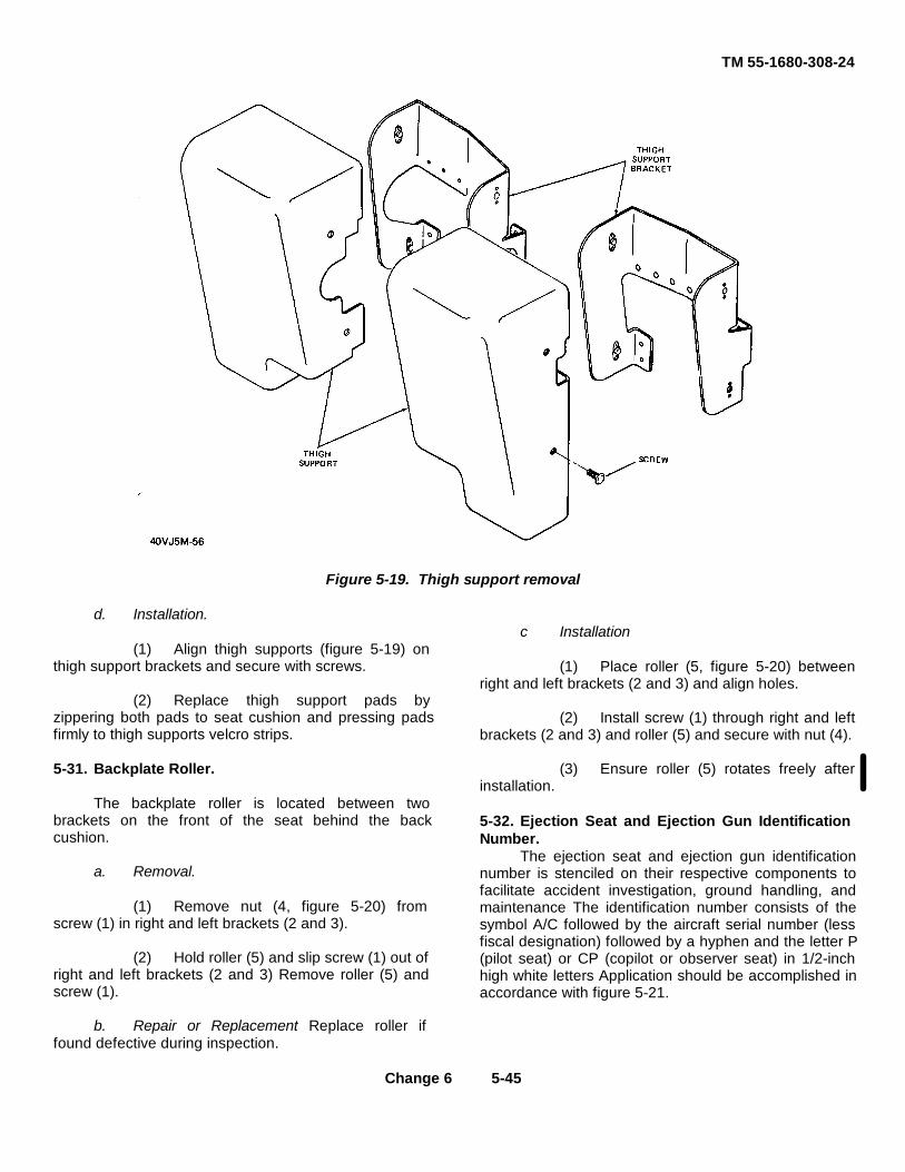
TM 55-1680-308-24
Figure 5-19. Thigh support removal
d. Installation.
(1) Align thigh supports (figure 5-19) onthigh support brackets and secure with screws.
(2) Replace thigh support pads byzippering both pads to seat cushion and pressing padsfirmly to thigh supports velcro strips.
5-31. Backplate Roller.
The backplate roller is located between twobrackets on the front of the seat behind the backcushion.
a. Removal.
(1) Remove nut (4, figure 5-20) fromscrew (1) in right and left brackets (2 and 3).
(2) Hold roller (5) and slip screw (1) out ofright and left brackets (2 and 3) Remove roller (5) andscrew (1).
b. Repair or Replacement Replace roller iffound defective during inspection.
c Installation
(1) Place roller (5, figure 5-20) betweenright and left brackets (2 and 3) and align holes.
(2) Install screw (1) through right and leftbrackets (2 and 3) and roller (5) and secure with nut (4).
(3) Ensure roller (5) rotates freely afterinstallation.
5-32. Ejection Seat and Ejection Gun IdentificationNumber.
The ejection seat and ejection gun identificationnumber is stenciled on their respective components tofacilitate accident investigation, ground handling, andmaintenance The identification number consists of thesymbol A/C followed by the aircraft serial number (lessfiscal designation) followed by a hyphen and the letter P(pilot seat) or CP (copilot or observer seat) in 1/2-inchhigh white letters Application should be accomplished inaccordance with figure 5-21.
Change 6 5-45
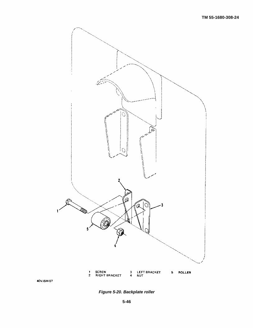
TM 55-1680-308-24
Figure 5-20. Backplate roller
5-46

TM 55-1680-308-24
Figure 5-21. Ejection seat and ejection gun identification number location
5-47

TM 55-1680-30824
Section II. PREPARATION FOR STORAGE AND RESHIPMENT
5-33. Uncrating, Unpacking, Storage, and ReshipmentInstructions.
The following instructions are for completeuncrating, unpacking, storage, and reshipment of the MK-JSD Ejection Seat.
Observe handling instructions printed on outsideof shipping container.
a. Uncrating. (See Figure 5-22) To uncrate theMK-JSD Ejection Seat, proceed as follows:
(1) Place shipping container in horizontalposition, facing up.
(2) Remove packing straps.
(3) Remove red circled screws and cornergussets in top of shipping container and remove cover.
(4) Remove two nuts and two washersfrom bolts securing upper seat brace to shippingcontainer.
(5) Withdraw two bolts and remove upperseat brace from shipping container.
(6) Remove four screws from each blocksecuring lower seat brace.
(7) Remove blocks and withdraw lowerseat brace from shipping container.
Figure 5-22. Ejection seat in container
5-48

TM 55-1680-308-24
(8) Remove two nuts and two washers andwithdraw two bolts securing wedge at top of ejectionseat. Remove wedge. (See figure 5-23.)
WARNING
Exercise care when lifting seat fromshipping container Shipping weight ofseat is approximately 125 pounds
(9) Remove ejection seat from shlppmgcontainer, lifting top of seat first, and place seat onsecure flat surface.
b Unpacking. (See figure 5-24) To unpack the MK-JSD Ejection Seat, proceed as follows
(1) Open plastic bag at top of seat only andremove seat from plastic bag.
(2) Remove items included with seat shipment(Refer to table 5-2.)
NOTE
Retain plastic bag and two sacks ofdesiccant from ejection seat bucket, foruse in repacking.
(3) Remove remainder of wrappings from seat.
(4) Slide seat cradle mounting rail into positionon seat back and secure upper and lower quick releasepins.
(5) Mount ejection seat on seat cradle (Seefigure5-25 )
c. Storage. The methods and materials used in thepreparation of the MK-J5D Ejection Seat for storage areidentical with the methods and materials used inpreparing the ejection seat for reshipment
d.Reshipment. The following instructions forpreparation of the MK-J5D Ejection Seat for reshipmentare applicable to the Organizational level ofmaintenance
(1) Place shipping pallet (figure 5-26) on levelarea and locate ejection seat on top of shipping pallet.
Figure 5-23. Wedge at head of seat (in position)5-49

TM 55-1680-308-24
Figure 5-24. Election seat with outer wrapping removed
(2) Install items listed in table 4-3 and twosacks of desiccant in seat bucket. (Sacks of desiccantwere retained when seat was unpacked).
(3) Wrap seat securely in sheet of plastic (Seefigure 5-24.)
(4) Insert seat in plastic bag. (Plastic bag whichwas retained when seat was unpacked.)
WARNING
Exercise care when lifting seat. Shippingweight of seat Is approximately 125 pounds.
(5) Insert ejection seat, bottom first, intoshipping container.
(6) Install wedge at top of ejection seat (figure5-23) Install two bolts, two washers and nuts to securewedge.
(7) Install lower seat brace (figure 5-22) andsecure each seat brace block with four screws.
(8) Install upper seat brace (figure 5-22) andsecure with bolts, washers, and nuts.
(9) Install shipping container cover and securewith screws in red circles on cover.
(10) Install packing straps.
5-34. Repair Parts and Special Tools.
Refer to TM 55-1510-204-23P, Appendix A.
Change 8 5-50

TM 55-1680-308-24
Table 5-2. Items Included With Seat Shipment
Nomenclature Part No Quantity
Handwheel MBEU/26528 1
Retaining collar MBEU/16711 1
Leg garter MBEU/8507 1
Leg garter MBEU/30-J5 1
Top latch plunger MBEU/26609 1
Top latch plunger spring MBEU/6617 1
Drogue shackle MBEU/5940 1
Shackle bolt MBEU/12064 1
Shackle nut A 1264 1
Floor bracket MBEU/3666 2
Quick-release pin MBEU/1434 2
Quick-release pin MBEU/3325 1
Quick-release pin MBEU/3921 1
Operating rod MBEU/400-24 1
Pin SP4Y A2 2
Bushing for manual MBEU/1081GRU5override handle
Link MB400-54 1
Pin SP4Y-A3 1
Split pin SP9-C4 3
Double cleat MBEU/186J5 1
Mushhead bolt A 133 1/2C 1
Stiffnut A 126-C 1
Washer SP.122-C 1
5-51

TM 55-1680-308-24
Figure 5-25. Ejection seat cradle part no. 105GT1040
Figure 5-26. Shipping Pallet for MK-J5D ejection seat
5-52

TM 55-1680-308-24
CHAPTER 6
DIFFERENCE DATA SHEETS
(Not Applicable)
Since only one model of the ejection seat is to be covered in thismanual, Difference Data Sheets are not applicable
6-1/(6-2 blank)

TM 55-1680-308-24
APPENDIX A
REFERENCES
NO. TITLE
TM 9-1300-206 Care, Handling, Preservation and Destruction of Ammunition
TM 9-1377-200-20&P Organizational Maintenance Manual (Including Repair Parts and SpecialTools List) Cartridges, Cartridge Actuated Devices and Propellant Ac-tuated Devices
TM 10-1670-250-20 Organizational Maintenance Manual (Including Repair Parts andSpecial Tools List) Parachute System used with Martin Baker MK-J5D Ejection Seat
TM 43-0001-39 Army Data sheets for Cartridges, Cartridge Actuated Devices and PropellantActuated Devices
TM 55-1500-204-25/1 General Aircraft Maintenance Manual
TM 55-1510-204-10/3 Operator's Manual' OV-1B Aircraft
TM 55-1510-204-10/4 Operator's Manual: OV-1C Aircraft
TM 55-1510-204-23P Aviation Unit and Intermediate Maintenance Repair Parts andSpecial Tools List (Including Depot Maintenance Repair Parts andSpecial Tools)
TM 55-1510-213-10 Operator's Manual: OV-1D/RV-1D Aircraft
TM 55-1510-204-23 Aviation Unit and Intermediate Unit Maintenance ManualOV-1B/OV-1C Aircraft
TM 55-1510-213-23 Aviation Unit and Intermediate Unit Maintenance ManualOV-1D/RV-1D Aircraft
TM 55-1510-217-PMD OV-1B, OV-1C, OV-1D and RV-1D Aircraft Preventive Maintenance Daily
TM 55-1510-217-PM OV-1/RV-1 Series Aircraft Phased Maintenance Checklist.
DA PAM 738-751 Functional Users Manual for the Army Maintenance Management System -Aviation (TAMMS-A)
Change 8 A-1/(A-2 blank)

TM 55-1680-308-24
APPENDIX B
BASIC ISSUE ITEMS LIST
(Not Applicable)
B1/(B-2 blank)

TM 55-1680-308-24APPENDIX C
PRELIMINARY MAINTENANCE ALLOCATION CHART
C-1. General.
a. The Maintenance Allocation Chart assignsmaintenance functions to the lowest level ofmaintenance based on past experience and thefollowing consideration,
(1) Skills available
(2) Time required
(3) Tools and test equipment required andavailable,
b. Only the lowest level of maintenance authorizedto perform a maintenance function is indicated.
c. A maintenance function assigned to amaintenance level will automatically be authorized to beperformed at any higher maintenance level.
d. A maintenance function that cannot beperformed at the assigned level of maintenance for anyreason may be evacuated to the next highermaintenance organization. Higher maintenance levelswill perform the maintenance functions of lowermaintenance levels when required or directed by theappropriate commander.
e. The assignment of a maintenance function willnot be construed as authority to carry the associatedrepair parts in stock. Authority to requisition, stock, orotherwise secure necessary repair parts will be asspecified in the repair parts appendix.
f. Normally there will be no deviation form theassigned level of maintenance In cases of operationalnecessity, maintenance functions assigned to amaintenance level may, on a one-time basis and at therequest of the lower maintenance level, be specificallyauthorized by the maintenance officer of the level ofmaintenance to which the function is assigned. Thespecial tools, equipment, etc., required by the lowerlevel of maintenance to perform this function will befurnished by the maintenance level to which the functionis assigned. This transfer of a maintenance function toa lower maintenance level does not relieve the highermaintenance level of the responsibility of the function.The higher level of maintenance has the authority todetermine.
(1) If the lower level is capable of performingthe work.
(2) If the lower level will require assistance ortechnical supervision and on-site inspection.
(3) If the authorization will be granted,
g. Changes to the Maintenance Allocation Chartwill be based on continuing evaluation and analysis byresponsible technical personnel and on reports receivedfrom field activities.
C-2. Definitions.
a. Inspect To determine serviceability of an itemby company its physical, mechanical, and electricalcharacteristics with established standards.
b Test To verify serviceability and to detectelectrical or mechanical failure by the use of testequipment.
c. Service To clean, to preserve, to charge, and toadd fuel, lubricants, cooling agents, and air.
d. Adjust To rectify to the extent necessary to bringinto proper operating range.
e. Align To adjust specified variable elements ofan item to bring to optimum performance.
f. Calibrate To determine the corrections to bemade in the readings of instruments or test equipmentused in precise measurement. Consists of thecomparison of two instruments, one of which is acertified standard of known accuracy, to detect andadjust any discrepancy in the accuracy of the instrumentor test equipment being compared with the certifiedstandard.
g Install To set up for use in an operationalenvironment such as an emplacement, site, or vehicle
h. Replace To replace unserviceable items withserviceable assemblies, subassemblies, or parts
I. Repair To restore an item to serviceablecondition through correction of a specific failure orunserviceable condition. This includes, but is not limitedto, inspection, cleaning, preserving, adjusting, replacing,welding, riveting, and strengthening
Change 6 C-1
TM 55-1680-308-24
j Overhaul To restore an item to a completelyserviceable condition as prescribed by maintenanceserviceability standards prepared and published for thespecific item to be overhauled.
k. Rebuild To restore an item to a standard asnearly as possible to the original or new condition mappearance, performance, and life expectancy. This isaccomplished through the maintenance technique ofcomplete disassembly of the item, inspection of all partsor components, repair or replacement of worn orunserviceable elements (Items) using originalmanufacturing tolerances and specifications, andsubsequent reassembly of the item.
C-3. Symbols.
a. The symbols 0, F, H, and D representOrganizational maintenance (O), Direct Supportmaintenance (F), General Sup- port maintenance (H),and Depot maintenance (D) and when placed on theMaintenance Allocation Chart, indicates the lowest levelof maintenance responsible for performing the particularmaintenance function.
Maintenance levels higher than the level ofmaintenance marked by the symbol are authorized toper- form the indicated function. b. The symbol % %applies to organizational maintenance and indicates thatthe particular maintenance function may be performedprovided it is specifically authorized by the directsupport maintenance officer. In no case will the directsupport maintenance officer require the accomplishmentof a % % maintenance function by an organization orunit and in no case will a % % function authorizestockage of parts at organization level.
c. The symbol (*) in column 3 and 4 of the MACdenotes that a special tool is required to perform theindicated maintenance function.
d. The symbols (1 and 2) in column 3 of the MACrefer to footnotes on page (C-10) of the MAC.
C-2

TM 55-1680-308-24
C-3
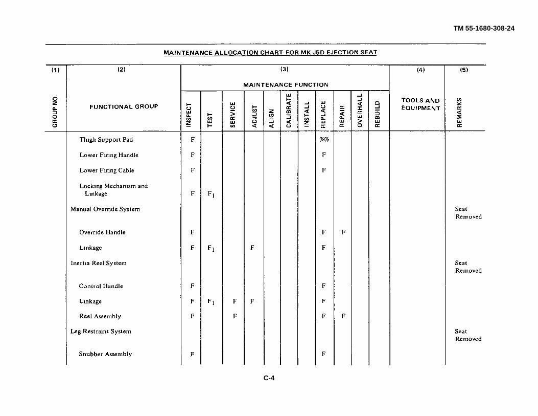
TM 55-1680-308-24
C-4
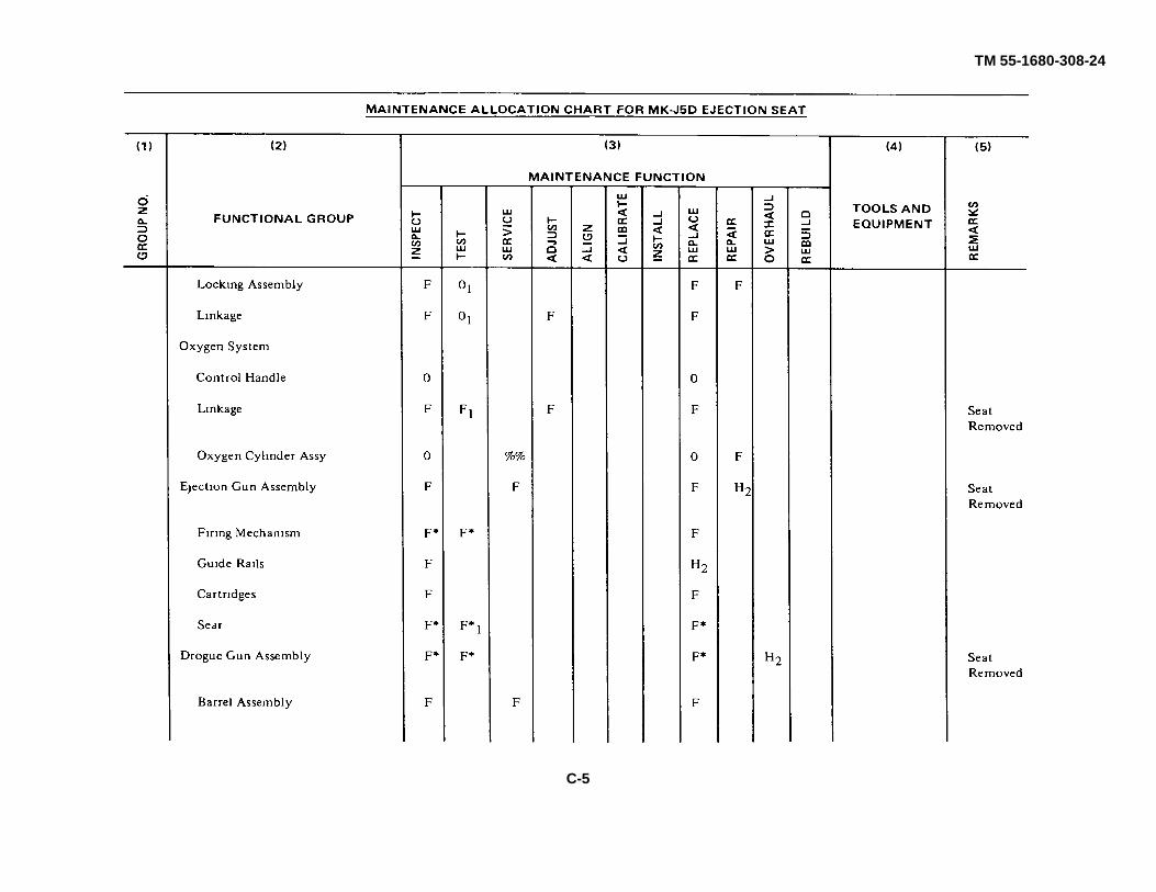
TM 55-1680-308-24
C-5

TM 55-1680-308-24
C-6

TM 55-1680-308-24
C-7/C-8 blank)


The Metric System and Equivalents
Linear Measure Liquid Measure
1 centiliter = 10 milliters = .34 fl. ounce1 centimeter = 10 millimeters = .39 inch 1 deciliter = 10 centiliters = 3.38 fl. ounces1 decimeter = 10 centimeters = 3.94 inches 1 liter = 10 deciliters = 33.81 fl. ounces1 meter = 10 decimeters = 39.37 inches 1 dekaliter = 10 liters = 2.64 gallons1 dekameter = 10 meters = 32.8 feet 1 hectoliter = 10 dekaliters = 26.42 gallons1 hectometer = 10 dekameters = 328.08 feet 1 kiloliter = 10 hectoliters = 264.18 gallons1 kilometer = 10 hectometers = 3,280.8 feet
Square MeasureWeights
1 sq. centimeter = 100 sq. millimeters = .155 sq. inch1 centigram = 10 milligrams = .15 grain 1 sq. decimeter = 100 sq. centimeters = 15.5 sq. inches1 decigram = 10 centigrams = 1.54 grains 1 sq. meter (centare) = 100 sq. decimeters = 10.76 sq. feet1 gram = 10 decigram = .035 ounce 1 sq. dekameter (are) = 100 sq. meters = 1,076.4 sq. feet1 decagram = 10 grams = .35 ounce 1 sq. hectometer (hectare) = 100 sq. dekameters = 2.47acres1 hectogram = 10 decagrams = 3.52 ounces 1 sq. kilometer = 100 sq. hectometers = .386 sq. mile1 kilogram = 10 hectograms = 2.2 pounds1 quintal = 100 kilograms = 220.46 pounds Cubic Measure1 metric ton = 10 quintals = 1.1 short tons
1 cu. centimeter = 1000 cu. millimeters = .06 cu. inch1 cu. decimeter = 1000 cu. centimeters = 61.02 cu. inches1 cu. meter = 1000 cu. decimeters = 35.31 cu. feet
Approximate Conversion Factors
To change To Multiply by To change To Multiply by
inches centimeters 2.540 ounce-inches Newton-meters .007062feet meters .305 centimeters inches .394yards meters .914 meters feet 3.280miles kilometers 1.609 meters yards 1.094square inches square centimeters 6.451 kilometers miles .621square feet square meters .093 square centimeters square inches .155square yards square meters .836 square meters square feet 10.764square miles square kilometers 2.590 square meters square yards 1.196acres square hectometers .405 square kilometers square miles .386cubic feet cubic meters .028 square hectometers acres 2.471cubic yards cubic meters .765 cubic meters cubic feet 35.315fluid ounces milliliters 29,573 cubic meters cubic yards 1.308pints liters .473 milliliters fluid ounces .034quarts liters .946 liters pints 2.113gallons liters 3.785 liters quarts 1.057ounces grams 28.349 liters gallons .264pounds kilograms .454 grams ounces .035short tons metric tons .907 kilograms pounds 2.205pound-feet Newton-meters 1.356 metric tons short tons 1.102pound-inches Newton-meters .11296
Temperature (Exact)
°F Fahrenheit 5/9 (after Celsius °Ctemperature subtracting 32) temperature

PIN: 022314 - 000

This fine document...
Was brought to you by me:
Liberated Manuals -- free army and government manuals
Why do I do it? I am tired of sleazy CD-ROM sellers, who take publicly available information, slap “watermarks” and other junk on it, and sell it. Those masters of search engine manipulation make sure that their sites that sell free information, come up first in search engines. They did not create it... They did not even scan it... Why should they get your money? Why are not letting you give those free manuals to your friends?
I am setting this document FREE. This document was made by the US Government and is NOT protected by Copyright. Feel free to share, republish, sell and so on.
I am not asking you for donations, fees or handouts. If you can, please provide a link to liberatedmanuals.com, so that free manuals come up first in search engines:
<A HREF=http://www.liberatedmanuals.com/>Free Military and Government Manuals</A>
– SincerelyIgor Chudovhttp://igor.chudov.com/
– Chicago Machinery Movers