TM-150-2 Traffic Signal Controller - Motus -...
62
TM-150-2 Traffic Signal Controller Training Notes
Transcript of TM-150-2 Traffic Signal Controller - Motus -...

TM-150-2 Traffic Signal Controller
Training Notes
Motus Traffic Limited Controller Training Notes
MOTUS/139/075000/005/1 Page ii
INTENTIONALLY BLANK

Motus Traffic Limited 2015 Controller Training Notes
Page iii MOTUS/139/075000/005/1
Copyright Notice © Copyright Motus Traffic Limited 2015 The information contained in this document is subject to change without notice. This document contains proprietary information that is protected by copyright. All rights are reserved. No part of this document may be reproduced or translated to another language without the prior written consent of Motus Traffic. Motus Traffic will not be liable for errors contained herein or for incidental or consequential damages (including lost profits) in connection with the furnishing, performance or use of this material whether based on warranty, contract, or other legal theory. Document: TM-150-2 Traffic Signal Controller Training Notes Date: September 2015 Motus Traffic Ltd 342 Coleford Road Sheffield S9 5PH
For product information and customer support please contact:
Iain Ross at Motus Traffic
mail: [email protected] Phone: +44 1142 617 394

Motus Traffic Limited Controller Training Notes
MOTUS/139/075000/005/1 Page iv
Contents 1. Course Content ......................................................................................................................................... 1
1.1 Appreciation Course .......................................................................................................................... 1
2. Basic Traffic Principles and Terms ........................................................................................................... 2
2.1 Hardware ........................................................................................................................................... 2
2.2 Phases, Stages and Streams ............................................................................................................ 2
2.3 Control Methods ................................................................................................................................ 2
2.4 User Notes ......................................................................................................................................... 3
3 Traffic Signal Controller ............................................................................................................................ 4
3.1 Introduction to the Traffic Signal Controller ....................................................................................... 4
3.2 Controller Functions ........................................................................................................................... 5
3.3 Rack Mounted Hardware ................................................................................................................... 6
3.3.1 Front View .................................................................................................................................. 6
3.3.2 Rear View .................................................................................................................................. 7
3.3.3 Linux CPU Card ......................................................................................................................... 8
3.3.4 Safety CPU Card ....................................................................................................................... 8
3.3.5 Internal 16in-8out Digital I/O Card ........................................................................................... 10
3.3.6 ITC-30 Power Supply ............................................................................................................... 11
3.3.7 Lamp Switch Card ................................................................................................................... 12
3.3.8 RS422 Adaptor for External I/O ............................................................................................... 13
3.3.9 Front Panel Hardware .............................................................................................................. 13
3.4 Cabinet Mounted Hardware ............................................................................................................. 16
3.4.1 Panel Layout ............................................................................................................................ 17
3.4.2 Logic PSU ................................................................................................................................ 20
3.4.3 Safety CPU I/O Expansion Card.............................................................................................. 20
3.4.4 I/O Expansion Card ................................................................................................................. 21
3.4.5 Dimming Transformer .............................................................................................................. 22
3.4.6 External Digital I/O Pod ........................................................................................................... 23
3.4.7 Mains Distribution Unit ............................................................................................................. 24
3.4.8 Dimming ................................................................................................................................... 24
3.5 Service Functions ............................................................................................................................ 25
3.5.1 User Access Levels ................................................................................................................. 25
3.5.2 Basic Service Functions .......................................................................................................... 26
3.6 Status Monitoring ............................................................................................................................. 28
3.6.1 Detector Logic Status .............................................................................................................. 28
3.6.2 Input Status .............................................................................................................................. 28
3.6.3 Output Status ........................................................................................................................... 28
3.7 Fault Diagnostics ............................................................................................................................. 29
3.7.1 Overview .................................................................................................................................. 29
3.7.2 Response to Major Faults and Fatal Errors ............................................................................. 29
3.7.3 Response to Minor Faults and Errors ...................................................................................... 29
3.7.4 Displaying Error Codes ............................................................................................................ 30
3.7.5 Example of Interrogating an Error............................................................................................ 30

Motus Traffic Limited 2015 Controller Training Notes
Page v MOTUS/139/075000/005/1
3.8 Handset Commands ........................................................................................................................ 32
3.8.1 Set Up ...................................................................................................................................... 32
3.8.2 Syntax and Formatting ............................................................................................................. 32
3.8.3 Level Access Commands ........................................................................................................ 33
3.8.4 Basic Commands ..................................................................................................................... 34
3.8.5 CLF ACT Command (for CLF Influence, stage and time) ....................................................... 35
3.8.6 Useful Pass-Through Commands............................................................................................ 35
4 TM-150-2 Integrated Web Interface ........................................................................................................ 36
4.1 Logging In ........................................................................................................................................ 36
4.1.1 Physical Connection ................................................................................................................ 36
4.1.2 Remote Connection ................................................................................................................. 36
4.1.3 Login Page ............................................................................................................................... 36
4.2 Overview Tab ................................................................................................................................... 37
4.3 Log Tab ............................................................................................................................................ 38
4.4 Traffic Analysis Tab ......................................................................................................................... 38
4.4.1 Lamp Status Tab ..................................................................................................................... 38
4.4.2 Stripes Tab ............................................................................................................................... 39
4.4.3 Traffic Count Tab ..................................................................................................................... 40
4.5 Management Tab ............................................................................................................................. 40
4.5.1 Configuration Tab .................................................................................................................... 41
4.5.2 My Account Tab ....................................................................................................................... 42
4.5.3 Users Tab ................................................................................................................................ 43
4.6 Current User Sessions Tab ............................................................................................................. 44
4.7 Log Out Tab ..................................................................................................................................... 44
5 Full Error Listing ...................................................................................................................................... 45
5.1.1 Event Log Annotation .............................................................................................................. 52
5.1.2 Plan Change Log Annotation ................................................................................................... 53
6 Glossary .................................................................................................................................................. 54
7 Parts List ................................................................................................................................................. 55


Motus Traffic Limited 2015 Controller Training Notes
Page 1 MOTUS/139/075000/005/1
1. Course Content
1.1 Appreciation Course • Introductions and course overview
• Health and Safety
• Basic Traffic Principles and Terms (Optional)
• Introduction to the controller hardware
• Controller Layout (block diagram)
• Cabinet Access
• Controller Rack
• Cards
• Display panel
• MDU
• Dimming Transformer
• Side Panel for I/O
• Back Panel
• Aux PSU & Dimming Panel
• Linked Dimming
• PRACTICAL
• Removing and Replacing components
• Review and Q&A
• Basic Service operations
• Code Levels
• Flash Testing
• Dimming
• Learning Lamp Loads
• Front Panel Operations
• I/O monitoring
• MANUAL Mode
• Viewing Basic Timing Parameters through the Front Panel
• PRACTICAL
• Basic Service Operations
• Front Panel Operations
• Handset Commands
• REVIEW and Q&A
• Fault Finding
• Types of Fault
• Serious (Fatal) Errors i.e. lamps extinguished
• Non-Fatal
• Detector Fault
• Lamp Fault
• Viewing errors and historical logs
• REVIEW and Q&A

Motus Traffic Limited Controller Training Notes
MOTUS/139/075000/005/1 Page 2
2. Basic Traffic Principles and Terms In this section:
Hardware
Phases, Stages and Streams
Control Methods
Dartford Controller Configuration
This section is aimed at anyone new to Traffic Signals and gives a brief overview of the terms used throughout this guide and outlines some of basic principles of traffic control.
2.1 Hardware Traffic Lights are operated by microprocessor controlled Traffic Signal Controllers, generally known simply as controllers in the industry. Lights are located in Signal Heads, mounted on poles. The controllers take a single phase mains electricity supply and control this supply to the different signal heads via multi-core signal cables to light the different Aspects in the head. There are two types of supply to the signals, Low Voltage, LV which is 230VAC, and Extra Low Voltage, ELV, which is 48VAC. A standard head consists of three 200 mm diameter aspects, Red at the top, Amber in the middle, and Green at the bottom. The controllers sequence the head to light the individual aspects in it through Red, Starting Amber (Red and Amber together) to Green, and then Leaving Amber (Amber on its own) back to Red again. The aspects can be halogen lamp, or LED. Halogen signals are always LV, using a transformer in the head for each aspect, however LED signals can be LV or ELV. The controller will monitor the aspects for current and can sense when an aspect has failed and log this fault. Traffic Signal Controllers can also be connected to a plethora of detection hardware to sense the presence of pedestrians, cyclists and vehicles passing through the junction.
2.2 Phases, Stages and Streams Traffic Signal heads on a junction are grouped into phases, which signal one approach to a junction. The term phase should not be confused with electrical phases. The electrical connection from a controller phase drive output consists of three live lines, Red, Amber and Green. There is also a common neutral bus usually shared by each phase being used in the controller. Usually neutral line for each phase will run to the pole, so if a pole has two heads of differing phases, there will be a total of eight cores required in that cable. It is common for more than one approach to an intersection to be given a green light at the same time if they do not conflict with each other. For example opposite sides of a crossroad or opposing left turns. The controller keeps these phases that can run together, as a collection in a stage. UK controllers are stage based, which means that they drive stages rather than phases. At the simplest level, the controller will sequence each stage, in a pre-defined order, for a fixed amount of green time, known as Fixed Time. If there is vehicle and pedestrian detection available to the controller, it may choose which stages to run and for how long according to vehicle demands from detection on the street, known as Vehicle Actuated or VA. In VA there are defined phase maximum green times so the controller will change stage when these timers run out even if traffic is still being detected on that phase. A collection of stages is known as a stream. Many junctions just have one stream, but certain designs lend themselves to having more than one stream. Usually the stages in the separate streams do not conflict with each other, such as on large roundabouts, where each arm off the roundabout is separated by some distance. Another common use for dual stream is pedestrian crossings over a dual carriageway, or where there is an separate pedestrian facility a short distance from the junction. Each stream can run a different control method or mode independently of the other streams.
2.3 Control Methods In addition to Fixed Time or VA modes of control, there are Manual and Urban Traffic Control (UTC) modes which are often used. In manual control, the stages can be driven using numeric buttons on the front panel of
Motus Traffic Limited 2015 Controller Training Notes
Page 3 MOTUS/139/075000/005/1
the controller, which will drive the requested stage or stages if more than one stream, indefinitely until Manual mode is released or the operator selects another stage button. The controller may also be told which stages to run by a central computer, which could be overseeing co-ordination of several junctions in a region. The central computer will communicate with a special piece of hard ware called an Outstation, which communicates with the controller serially or by control and reply wires connected directly to the controller.
2.4 User Notes

Motus Traffic Limited Controller Training Notes
MOTUS/139/075000/005/1 Page 4
3 Traffic Signal Controller In this section:
Introduction to the Traffic Signal Controller Hardware
Controller Functions
Rack Mount Hardware
Cabinet Mount Hardware
Service Functions
Status Monitoring
Faults
3.1 Introduction to the Traffic Signal Controller The Motus TM-150-2 Traffic Signal Controller is a rack mount, modular design developed according to national and European standards. The product fits into a standard 19-inch rack, with the internal cards having a Euro 3H slot form-factor. It is installed into a standard case on a swing frame for ease of access to the rear of the rack. The case is fitted with aluminium panels which house some ancillary equipment and connections to the street wiring. The most commonly used version is the 16 Phase ELV type, wired for 8 phases. The cabinet is locked with two T-Key bolts at the top and bottom of the right hand side of the door. An additional S18 key lock is located in the middle of the door. There is a manual panel access flap which is operated by means of a Type 900 Key. All keys can be provided by Motus Traffic upon request.
Figure 3.1 – TM-150-2 Traffic Signal Controller
Motus Traffic Limited 2015 Controller Training Notes
Page 5 MOTUS/139/075000/005/1
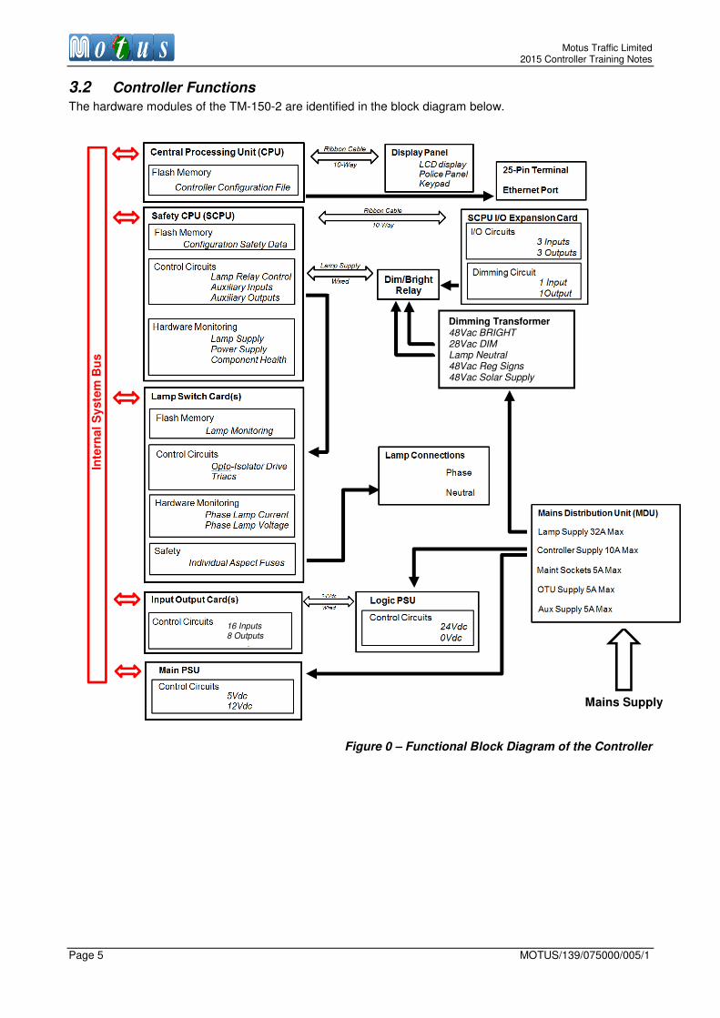
3.2 Controller Functions
The hardware modules of the TM-150-2 are identified in the block diagram below.
Figure 0 – Functional Block Diagram of the Controller
Inte
rnal
Syste
m B
us
Mains Supply
Dimming Transformer 48Vac BRIGHT 28Vac DIM Lamp Neutral 48Vac Reg Signs 48Vac Solar Supply
16 Inputs 8 Outputs

Motus Traffic Limited Controller Training Notes
MOTUS/139/075000/005/1 Page 6
3.3 Rack Mounted Hardware
The Controller Rack is mounted on the cabinet swing frame and contains the hardware modules described below.
Table 3.3 Core Rack Mount Modules
Module Function
Power supply
Provides a regulated power supply for the rack mounted hardware
12V and 5V are supplied from here. 24VDC is provided by the logic PSU (mounted in the cabinet)
Lamp Relays The Amber and Red/Green Lamp Relays are situated to the left of the power supply unit. They are controlled by the Safety CPU
Main CPU card Linux CPU which runs the traffic control program
Safety CPU card Supervises the operation of the TM-150-2, and controls the Lamp Relays to safely shut down the controller in the event of failure
Internal I/O Card Internal I/O card, 16 input and 8 output. Used on smaller controllers.
RS422 adaptor card
This card locates in one of the internal Input / Output slots, and provides a connection for a 10 Way ribbon cable to communicate with the I/O pods used in larger controller builds, mounted elsewhere in the controller.
Lamp Switch Card(s)
Two-Phase Lamp Switch Cards drive the Traffic Signals. They provide Lamp monitoring facilities and contain individual phase colour channel fuses for safety. i.e. each colour of each phase has a fuse
Display Panel Provides a user interface for access to controller
Terminal Panel Provides Ethernet and RS232 Serial access to the controller. Contains auxiliary switches for Emergency All Red display
3.3.1 Front View The Controller Rack is a 16 phase version shown in Figure 3.3.1.1 below. The display panel hinges to the left and the panel covering the Lamp Switch Cards on the right side hinges on the bottom. The panels are secured with thumb screws, and should never be over-tightened with a screw-driver as the next person to visit might find them difficult to unscrew. The controller display has an LCD display, and several buttons for interrogating the controller. To the right of this panel is the part of the rack where the Safety CPU card and Lamp Switch Cards are housed. They have mimic and status LEDs which can be seen through holes drilled in the panel. The rack is actually 5U in height, and the bottom 2U houses a terminal plate with 25-Pin RS232 terminal and Ethernet socket. These provide additional means to interrogate the controller.
Figure 3.3.1.1 – Front View of the 16 Phase TM-150-2

Motus Traffic Limited 2015 Controller Training Notes
Page 7 MOTUS/139/075000/005/1
With the panels open access is gained to the cards housed inside the rack. The figure below shows the top 3U of the controller rack with the Display Panel and Lamp Switch Card Panel removed. The Lamp Relays, PSU, CPU and I/O RS422 Adapter for the external I/O pods are located behind the Display Panel. The Detector slots are not used unless SA/SDE is required. The Safety CPU and Lamp Switch cards are located behind the Lamp Switch Card Panel.
Figure 3.3.1.2 – Front View of the TM-150-2 with Panels Removed
3.3.2 Rear View The backplane of the controller rack is shown below. The numbered features are described in Table 3.3.2 with reference to the figure shown below.
Figure 3.3.2 Rear View of the TM-150-2 Backplane
Table 3.3.2 Backplane Components
Connector Description
1 to 3 Flat cable connectors to I/O Relay Isolator cards
7 to 8 Flat cable connectors for internal detector cards
11 10-Way IDC Ribbon Connector from Safety CPU I/O to Expansion Card
12 Police key (not used in UK controllers)
13 5VDC and 12VDC Internal power supply The +5VDC and 0VDC are used to power the 25-pin terminal.
14 Mains input (neutral, live and ground).
15 Switched Lamp Supply Neutral
16 Switched Lamp Supply Live
17 Lamp Switch Card outputs, Neutral, Red, Amber, Green
18 Switched Lamp Supply Live connection to Lamp Switch Cards
19 Fan connections
20 RS422 Driver and Backplane ID Programmable Integrated Circuit.
I/O slots Detectors (not used)
Lamp Switch Cards 1 to 8
Safety CPU
Amber Relay
Red/Green Relay
Power supply
CPU
11
3 2 1
13
14
15 16
17
8 7
19
18
12
20

Motus Traffic Limited Controller Training Notes
MOTUS/139/075000/005/1 Page 8
3.3.3 Linux CPU Card The Linux CPU card is shown in Figure 3.3.3. It is responsible for running the traffic control program and a webserver for the integrated web interface. The basic specifications (subject to change) are listed below:
• CPU: ARM 920T Processor
• ROM: 64MByte NAND Flash
• RAM: 32MByte
• RTC: M4T28-BR12SH1
Figure 3.3.3 The Linux CPU Card
COM5 is connected to the 25-Pin socket on the front of the controller which includes +5VDC power and ground, forming a TR2500-compliant terminal interface. The Ethernet port is an RJ-45 connector which is wired through to the front of the controller.
3.3.4 Safety CPU Card
The Safety CPU card is shown in Figure 3.3.4. While the Linux CPU card controls the traffic lights, the Safety CPU card supervises the running of the traffic control program, and monitors the health of the critical components such as Lamp Switch Cards and Linux CPU. This ensures that the TM-150-2 is operated in a safe way, ensuring that contentious or misleading traffic signals will never occur.
Figure 3.3.4 The Safety CPU Card
COM7
COM5
COM6
Ethernet
USB for 3G modem
Front panel connections
USB for upgrades
RJ-11 Terminal port
Diagnostics LEDs
Processor load LED

Motus Traffic Limited 2015 Controller Training Notes
Page 9 MOTUS/139/075000/005/1
The SCPU Monitoring includes the following:
• Signal conflicts (Correspondence monitoring and green conflict monitoring).
• Program control.
• Mains voltage and frequency.
• Signal state timings.
• Operating temperature.
• Lamp loads.
The SCPU card includes auxiliary I/O ports (4 x inputs and 4 x outputs). A summary of the LED status indicators is given in Table 3.3.3a.
Table 3.3.3a LED Indicators on The Safety CPU Card
LED Condition Remark
I/O Inputs 1 to 4 (Red) ON = input high. OFF = input low.
I/O Outputs 1 to 4 (Green) ON = output active. OFF = output inactive.
5V power (Green) ON = +5VDC OK. OFF = +5VDC Error.
12V power (Green) ON = +12VDC OK. OFF = +12VDC Error.
ERR Steady ON = Error. See the TM-150-2 Error Log
WD Flashing when OK. Watchdog
Y ON = Amber relay active. OFF = Amber relay inactive.
LED on the left: Intersection 1.
LED on the right: Intersection 2.
R/G ON = Red/Green relay active. OFF = Red/Green relay inactive.
LED on the left: Intersection 1.
LED on the right: Intersection 2.
Table 3.3.3b Safety CPU Pin Assignments
Table 3.3.3b shows the pin assignments for the 10-way ribbon cable that connects between the Safety CPU backplane connector and the Safety CPU I/O Expansion Card. Note that the polarity of the DC voltage received at pins 9 and 10 determines the normal state of the logic. In the TM-150-2 both pins set to +24VDC.
Terminal Description
1 In-1
2 In-2
3 In-3
4 In-4
5 Out-1
6 Out-2
7 Out-3
8 Out-4
9 Common-in 12 to 24 VDC
10 Common-out

Motus Traffic Limited Controller Training Notes
MOTUS/139/075000/005/1 Page 10
3.3.5 Internal 16in-8out Digital I/O Card
Optionally the controller can use internal or external I/O cards. The internal card supplies 16 digital inputs and 8 digital outputs and is shown in the figure below.
Figure 3.3.5 - The I/O Card (Side and Overhead Views)
• Eight outputs, with Green LED indicators. For isolation the Motus I/O Expansion card must be used.
• Sixteen inputs, opto-isolated with amber LED indicators.
• External voltage range of I/O: 12 to 48 VDC.
• Input impedance: 10 kΩ.
• Output current: 1A average, maximum 2A peak.
The inputs are routed to terminal blocks on the back panel of the cabinet. The outputs are typically routed to the Motus I/O expansion card.
The I/O card has three sets of jumpers for its configuration, which are annotated onto Figure 3.3.5. The jumpers select the following options:
1. Input polarity: Select Active High or Active Low (default). 2. Output default states: Enable Pull Up (default) or Pull Down. 3. Address assignment for multiple I/O cards: Select one of six values, N/A is default for card number 1.
In the event of replacing a faulty unit there may be a requirement to set the address of the I/O card during maintenance. Address assignment is accomplished through the jumper settings defined in table 3.3.5.
Table 3.3.5 Jumper Settings for I/O Pod Allocation
Address N/A +4 +2 +1 N/A Input Range Output Range
1 1 to 16 1 to 8
2 x 17 to 32 9 to 16
3 x 33 to 48 17 to 24
4 x x 49 to 64 25 to 32
5 x 65 to 80 33 to 40
6 x x 81 to 96 40 to 48
The card addresses in red (cards 4 to 6 inclusive) are only available when using the 32 phase version of the TM-150-2 which has six internal I/O slots. The standard 16 phase rack has 3 slots.
1
2
3
Motus Traffic Limited 2015 Controller Training Notes
Page 11 MOTUS/139/075000/005/1
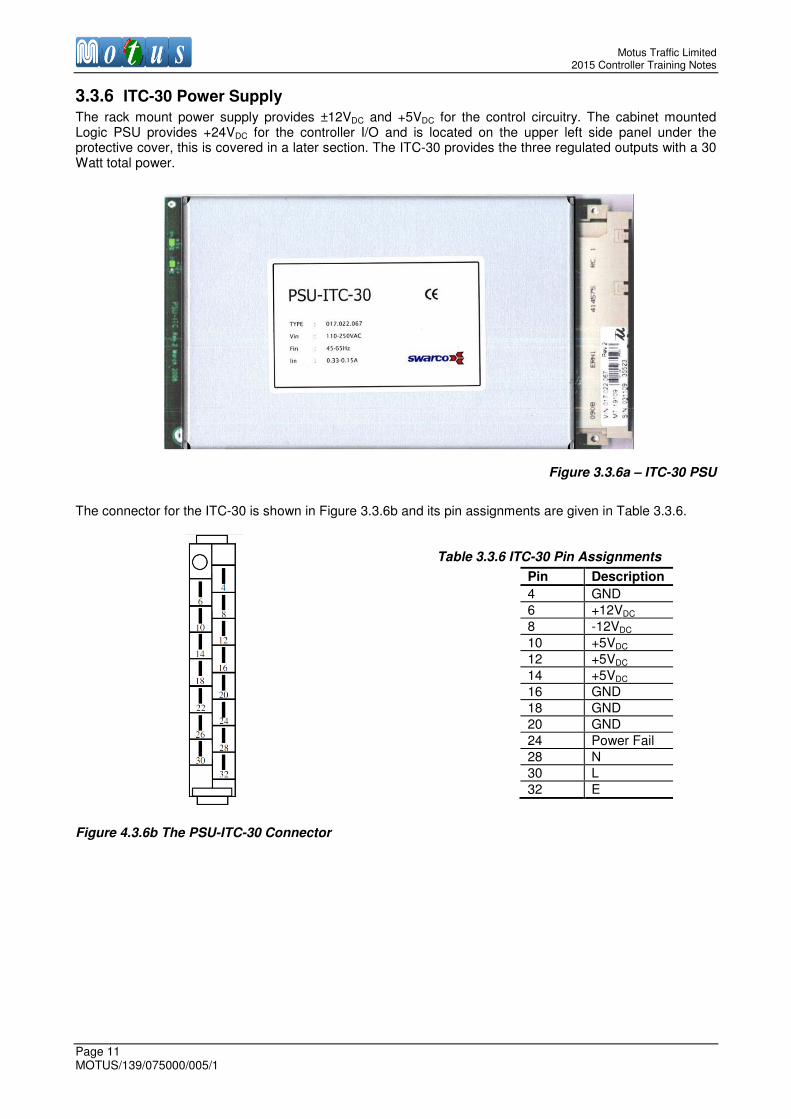
3.3.6 ITC-30 Power Supply
The rack mount power supply provides ±12VDC and +5VDC for the control circuitry. The cabinet mounted Logic PSU provides +24VDC for the controller I/O and is located on the upper left side panel under the protective cover, this is covered in a later section. The ITC-30 provides the three regulated outputs with a 30 Watt total power.
Figure 3.3.6a – ITC-30 PSU
The connector for the ITC-30 is shown in Figure 3.3.6b and its pin assignments are given in Table 3.3.6.
Table 3.3.6 ITC-30 Pin Assignments
Figure 4.3.6b The PSU-ITC-30 Connector
Pin Description
4 GND
6 +12VDC
8 -12VDC
10 +5VDC
12 +5VDC
14 +5VDC
16 GND
18 GND
20 GND
24 Power Fail
28 N
30 L
32 E

Motus Traffic Limited Controller Training Notes
MOTUS/139/075000/005/1 Page 12
3.3.7 Lamp Switch Card
The Lamp Switch Card is shown in Figure 3.3.7. It provides outputs to drive the traffic signal heads, with lamp monitoring, electrical isolation and fuse protection. The outputs are used for Red, Amber and Green signals. The Aux output occasionally used as a switched output and is not monitored.
Figure 3.3.7 – 230VAC Lamp Switch Card (48VAC looks the same but with some different components)
• Eight outputs, supporting two signal phases per card. (The fourth output on each phase is not used)
• Opto-isolation of each control signal.
• Triac drivers rated at 10A, each colour drive is individually protected by 3.15A slow-blow fuses.
• Intelligently monitored current and voltage on each output.
• LED indicators show the output status.
The eight LED indicators on the front panel of the card are arranged in two columns. The left column is for signal phase A and the right column is for signal phase B. The first three LEDs are mimics for the street colours displayed, Red, Amber and Green.
Situated underneath the Green mimic, the red status LED has two functions. In normal operation it indicates that the related signal phase has an error, usually either Level 1 or Level 2 lamp fault but also it could indicate a correspondence or green conflict fault. The second function is “Phase Status” and is activated via the front panel of the TM-150-2 in the following procedure:
1. Press the STATUS button, and the controller will display:
01 PHstat On/Off
02 Multiple Status
03 Ph lamp var.
04 Ph var.
Scroll down to the 01 PHstat On/Off option and press ENTER. The controller will display:
01 PHstat On/Off
Enabled= 0
^
2. Change the 0 to a 1 and press ENTER
The Status LED will now display the status of the phase according to Table 3.3.7 depending on which signal phase colour mimic LED is active.

Motus Traffic Limited 2015 Controller Training Notes
Page 13 MOTUS/139/075000/005/1
Table 3.3.7 Lamp Switch Card Status Indicators
Mimic LED Status LED OFF Status LED ON Status LED Flashing Slowly
Status LED Flashing Quickly
Red Resting Privilege Request Starting, extension
Green Red-Amber, minimum, max. Minimum
Passive, rest, fixed past-end -green
Extension Variable past-end-green
Amber Minimum Extension
3.3.8 RS422 Adaptor for External I/O
If the external I/O pods are used, then an adapter is plugged into any one of the three I/O slots, it does not matter which. This has a socket for a 10way ribbon cable. This cable is connected to the first I/O pod on the back panel and simply provides a communications bus to the I/O pods.
Figure 3.3.8.1 – RS422 Adaptor for External I/O
3.3.9 Front Panel Hardware
Basic user interaction with the TM-150-2 is achieved via its Display Panel, which provides access to parameters Basic user interaction with the TM-150-2 is achieved via its Display Panel, which provides access to parameters for review and adjustment, except those which are safety critical. Many of these parameters can only be set to values within predetermined limits specified by the programmed configuration. The front panel has a LCD screen and buttons, some of which include an LED indicator. Figure 3.3.9.1 shows front and rear views of the control panel.
Figure 3.3.9.1 Control Panel of the TM-150-2
The panel covers the Signal Relays, PSU, CPU card and I/O slots. It has hinges on the left hand side and it locks with two thumb-screws. It can easily be removed. The panel connects to the Linux CPU card with a 10-pin flat cable from the connector circled ‘A’ in the above figure.

Motus Traffic Limited Controller Training Notes
MOTUS/139/075000/005/1 Page 14
The LCD is backlit and the illumination brightness can be adjusted using the potentiometer circled ‘B’ in the above figure. The keypad on the control panel is partitioned into functionally separate regions, as highlighted in Figure 3.3.9.2.
Figure 3.3.9.2 Control Panel Keypad
The Interrogation Keypad is used for viewing configuration parameters, fault logs and I/O operation. New parameter values are validated according to level access and programmed limits before they are accepted by the controller. The Police Panel Keypad provides standard operating buttons for emergency services or other authorised personnel.
1.1.1.1 Interrogation Buttons
The top row of buttons selects the type of information to be displayed on the LCD. The arrow buttons allow the user to navigate through the menus. The button with a key symbol is for changing level access to the controller.
1.1.1.2 Police Panel
The buttons on the Police Panel Keypad are used to manually change the operating mode of the controller. A description of the buttons is presented in Table 3.3.9.1 below.
Table 3.3.9.1 Police Function Buttons
Button Function
SIGNALS ON Switches all traffic signals ON and initiates the start-up sequence.
SIGNALS OFF Switches all traffic signals OFF.
NORMAL Activates normal operation mode, unlatches the other mode buttons.
ALL RED Available only when configured and controller in MANUAL mode.
Forces all phases to red. Not used at present.
MANUAL Activates Manual control.
VA Activates VA control.
FIXED Activates Fixed Time control.
AUX SW1 Optional – often used for Selected CLF or Part Time modes.
Can be optionally unlatched by the NORMAL button if used as a mode select switch.
During Normal operation, the NORMAL button indicator will be illuminated. Pressing another mode button such as MANUAL or VA may change the operation mode if the mode priority allows the request. If permitted, the NORMAL button indicator will turn off and the active mode button indicator will then illuminate. Through a configuration option, the AUX SW1 button can function as a general purpose button when available during Normal mode. Alternatively, it can function as a mode select button, for example to select CLF.

Motus Traffic Limited 2015 Controller Training Notes
Page 15 MOTUS/139/075000/005/1
1.1.1.3 Information Displayed During Normal Operation Mode Under normal error-free operating conditions, and when no menu buttons have been pressed, the text-based LCD shows the information similar to that in Figure 3.3.9.3.
Figure 3.3.9.3 Example Display (Normal Error-Free Operation)
In the case of an error being detected, the display shows the error code and corresponding details. If the error is a FATAL error in which the signals have been extinguished, the display will alternate between the FATAL error message and the normal information once every second.
With reference to Figure 3.3.9.3, the information fields are explained in Table 3.3.9.2
Table 3.3.9.2 Explanation of Information Fields
Field / Parameter Function
** TM-150-2 Linux ** This indicates that the TM-150-2 is running Motus UK Linux Firmware, which is standard issue across the product range. Contact Motus Traffic if this is not seen on your particular controller.
12363
This is the unique serial number for the TM-150-2 unit. This number is linked to the backplane of the unit and will remain the same even if all cards are replaced, including the Main CPU card. If the controller is displaying *****
please contact Motus Traffic as the unit may be faulty.
24.03-14:05:40 This is the current date and time in dd.mm and hh:mm:ss formats.
P4MO
Plan number 4 is running with the MO (Mode Priority) modes source.
Other mode sources are: CL (Calendar Clock), FP (Forced), EM (Emergency
logic), CB (Control Block – Special Conditioning)
MOVA Current Mode. MOVA control. Other higher priority modes include UTC and HURRY.
0 Current Plan Cycle Time (e.g. CLF). If not applicable it will display 0.
1-1 Intersection 1 and stream 1. Press the 1 button to cycle through the different streams (lanes). The info to the right of this relates to the stream displayed.
ON Lamps are ON in this intersection. ON* means ON but the lamps are dim.
OK Means that everything is OK. In case of error, ERR or ER (if DIM) is
displayed.
S2/S2-0
Stage 2 is active and Stage 2 will be the next stage in the selected stream. 0 shows how long Stage 2 has been active, and if 0 it is resting in current
stage.
After fifteen minutes of keypad inactivity, the LCD backlight is automatically switched off to conserve power. Without illumination, the text is nearly invisible. Press the ESC button once to safely re-illuminate the LCD without disturbing the menu/page state.
Motus Traffic Limited Controller Training Notes
MOTUS/139/075000/005/1 Page 16
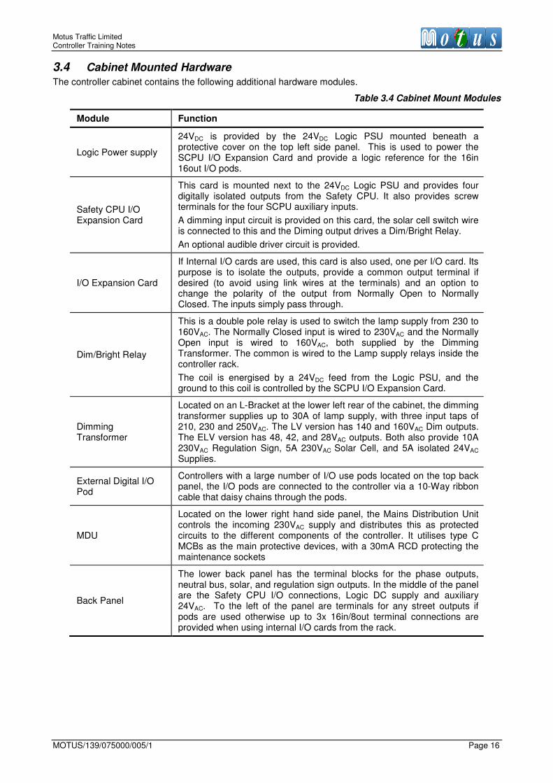
3.4 Cabinet Mounted Hardware
The controller cabinet contains the following additional hardware modules.
Table 3.4 Cabinet Mount Modules
Module Function
Logic Power supply
24VDC is provided by the 24VDC Logic PSU mounted beneath a protective cover on the top left side panel. This is used to power the SCPU I/O Expansion Card and provide a logic reference for the 16in 16out I/O pods.
Safety CPU I/O Expansion Card
This card is mounted next to the 24VDC Logic PSU and provides four digitally isolated outputs from the Safety CPU. It also provides screw terminals for the four SCPU auxiliary inputs.
A dimming input circuit is provided on this card, the solar cell switch wire is connected to this and the Diming output drives a Dim/Bright Relay.
An optional audible driver circuit is provided.
I/O Expansion Card
If Internal I/O cards are used, this card is also used, one per I/O card. Its purpose is to isolate the outputs, provide a common output terminal if desired (to avoid using link wires at the terminals) and an option to change the polarity of the output from Normally Open to Normally Closed. The inputs simply pass through.
Dim/Bright Relay
This is a double pole relay is used to switch the lamp supply from 230 to 160VAC. The Normally Closed input is wired to 230VAC and the Normally Open input is wired to 160VAC, both supplied by the Dimming Transformer. The common is wired to the Lamp supply relays inside the controller rack.
The coil is energised by a 24VDC feed from the Logic PSU, and the ground to this coil is controlled by the SCPU I/O Expansion Card.
Dimming Transformer
Located on an L-Bracket at the lower left rear of the cabinet, the dimming transformer supplies up to 30A of lamp supply, with three input taps of 210, 230 and 250VAC. The LV version has 140 and 160VAC Dim outputs. The ELV version has 48, 42, and 28VAC outputs. Both also provide 10A 230VAC Regulation Sign, 5A 230VAC Solar Cell, and 5A isolated 24VAC Supplies.
External Digital I/O Pod
Controllers with a large number of I/O use pods located on the top back panel, the I/O pods are connected to the controller via a 10-Way ribbon cable that daisy chains through the pods.
MDU
Located on the lower right hand side panel, the Mains Distribution Unit controls the incoming 230VAC supply and distributes this as protected circuits to the different components of the controller. It utilises type C MCBs as the main protective devices, with a 30mA RCD protecting the maintenance sockets
Back Panel
The lower back panel has the terminal blocks for the phase outputs, neutral bus, solar, and regulation sign outputs. In the middle of the panel are the Safety CPU I/O connections, Logic DC supply and auxiliary 24VAC. To the left of the panel are terminals for any street outputs if pods are used otherwise up to 3x 16in/8out terminal connections are provided when using internal I/O cards from the rack.
Motus Traffic Limited 2015 Controller Training Notes
Page 17 MOTUS/139/075000/005/1
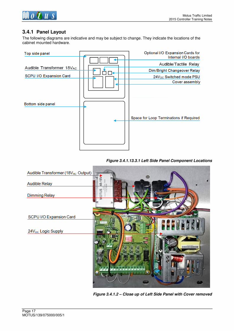
3.4.1 Panel Layout
The following diagrams are indicative and may be subject to change. They indicate the locations of the cabinet mounted hardware.
Figure 3.4.1.13.3.1 Left Side Panel Component Locations
Figure 3.4.1.2 – Close up of Left Side Panel with Cover removed
Motus Traffic Limited Controller Training Notes
MOTUS/139/075000/005/1 Page 18
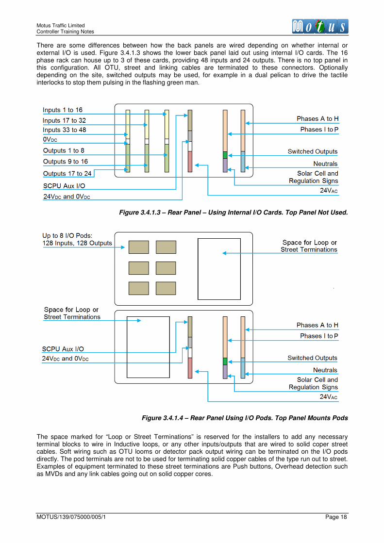
There are some differences between how the back panels are wired depending on whether internal or external I/O is used. Figure 3.4.1.3 shows the lower back panel laid out using internal I/O cards. The 16 phase rack can house up to 3 of these cards, providing 48 inputs and 24 outputs. There is no top panel in this configuration. All OTU, street and linking cables are terminated to these connectors. Optionally depending on the site, switched outputs may be used, for example in a dual pelican to drive the tactile interlocks to stop them pulsing in the flashing green man.
Figure 3.4.1.3 – Rear Panel – Using Internal I/O Cards. Top Panel Not Used.
Figure 3.4.1.4 – Rear Panel Using I/O Pods. Top Panel Mounts Pods
The space marked for “Loop or Street Terminations” is reserved for the installers to add any necessary terminal blocks to wire in Inductive loops, or any other inputs/outputs that are wired to solid coper street cables. Soft wiring such as OTU looms or detector pack output wiring can be terminated on the I/O pods directly. The pod terminals are not to be used for terminating solid copper cables of the type run out to street. Examples of equipment terminated to these street terminations are Push buttons, Overhead detection such as MVDs and any link cables going out on solid copper cores.

Motus Traffic Limited 2015 Controller Training Notes
Page 19 MOTUS/139/075000/005/1
On the right side of the controller is a panel housing the MDU.
Figure 3.4.1.5 – Right Side Panel Component Locations

Motus Traffic Limited Controller Training Notes
MOTUS/139/075000/005/1 Page 20
3.4.2 Logic PSU
24VDC is provided by the Logic PSU mounted beneath a protective cover on the top left side panel. This is used to power the SCPU I/O Expansion Card and provide a logic reference for the I/O cards or pods.
Figure 3.4.2 – Logic PSU
3.4.3 Safety CPU I/O Expansion Card
This card is used exclusively with the Safety CPU card and is identified by the 10-way ribbon connector shown in Figure 3.4.3 It has four inputs and four opto-isolated outputs, corresponding to the Auxiliary I/O provided on the Safety CPU card.
Figure 3.4.3 Safety CPU Expansion Card
There are two important circuits on this board. One is the dimming sense circuit, the other the audible circuit. The card can take in a voltage from a photo-electric cell in the range 24-230VAC. When the voltage is
Risk of electric shock! Ensure that the controller is powered down at the MASTER SWITCH before removing the top cover of the Left Side Panel. The heat sink on the Logic PSU is at mains potential when switched on.
Dimming Sense Circuit
JP2 and JP3: Safety CPU reference select for I/O
Power LED
SW1: Normally Open / Normally Closed select
3A Fuse Carrier protecting incoming 24 VDC
Incoming +24VDC Power Terminal
Output and Input connector to terminal blocks
Solar Cell Input
10-way Ribbon Cable Connection from controller
Audible Circuit

Motus Traffic Limited 2015 Controller Training Notes
Page 21 MOTUS/139/075000/005/1
sensed, this is then presented to SCPU IN-1 (controller input 65) as a 0VDC signal. The controller can then dim by driving the DIM/BRIGHT relay from SCPU OUT-4 (Controller Output 68). The audible circuit takes in an 18VAC voltage from the Audible Transformer, rectifies and then passes a switched ~20VDC @3A output to the back panel for Audibles to wire into. The switch is SCPU OUT-2 (Controller Output 66). If no audibles are to be used, then SCPU OUT-2 can be used as an extra standard Output.
1.1.1.4 Setting the Type of Common Used
Jumpers JP2 and JP3 set the type of common used by the Auxiliary I/O on the Safety CPU card. They should always be set to +24VDC to maintain active low inputs and pull up outputs.
Because of the typical applications of the Safety CPU outputs, no linked common is provided.
3.4.4 I/O Expansion Card
The internal I/O expansion card shown in Figure 3.4.4 isolates the digital outputs so as to provide the most flexible range of configuration options. On an individual basis, the outputs can be connected to 0VDC or +24VDC common, or be independent. The polarity of each output can be set to either normally open or normally closed. This card is paired with the internal I/O card having 16 inputs and 8 outputs. Up to three cards can be used in a 16 phase controller rack. This card is not used if external I/O pods are used.
Figure 3.4.4 Relay Isolator Card
Only change JP2 and/or JP3 to the 0V setting if instructed by Motus Traffic Technical Support.
For correct operation it is very important that this card is connected to Earth by coupling to the Aluminium mounting plate using a wire bond. Damage to the dimming sense circuit is likely to occur if not connected.

Motus Traffic Limited Controller Training Notes
MOTUS/139/075000/005/1 Page 22
Configuration is achieved by a combination of jumper settings and DIP switch positions.
1.1.1.5 Setting the Type of Output Common Used
Jumper JP1 sets whether the output common is 0VDC or +24VDC. The standard setting is 0VDC. To link an output to this common, simply set the corresponding switch on SW2.
1.1.1.6 Selecting Normally Open or Normally Closed Output
SW1 selects whether the outputs are normally open or normally closed. The switch is colour-coded 1 (Brown) to 8 (Grey). The direction of the switch is labelled on the card for Normally Open (NO) or Normally Closed (NC) operation. This is independent of whether or not the output is linked to the common.
3.4.5 Dimming Transformer
The LV dimming transformer supplies up to 30A of lamp supply, with three input taps of 210, 230 and 250VAC. It has 140 and 160VAC Dim outputs. It also provides fused 10A 230VAC Regulation Sign, 5A 230VAC
Solar Cell, and 5A isolated 24VAC Supplies.
Figure 3.4.5.1 Dimming Transformer (LV Type)
The ELV dimming transformer supplies up to 30A of lamp supply, with three input taps of 210, 230 and 250VAC. It has 28, 42 and 48VAC outputs. It also provides fused 10A 230VAC Regulation Sign, 5A 230VAC
Solar Cell, and 5A isolated 24VAC Supplies.
Figure 3.4.5.2 Dimming Transformer (ELV Type)
On the back panel output terminal block, the lower of each output pair is common.

Motus Traffic Limited 2015 Controller Training Notes
Page 23 MOTUS/139/075000/005/1
3.4.6 External Digital I/O Pod
The external I/O pod is shown in Figure 3.4.6. It is a DIN rail mounted pod, which has 16 digital inputs and 16 isolated digital outputs. The card is connected to the controller with a 10-Way ribbon cable from the RS422 Adaptor in the rack, located in any one of the three internal I/O slots. The next card is linked to the previous by the 10-Way Ribbon Cable The IN and OUT connection polarity is not important when daisy chaining the pods. The connectors are circled in blue in Figure 3.4.6.
Figure 3.4.6 – External Digital I/O Pod
• Sixteen inputs, opto-isolated with amber LED indicators.
• Sixteen outputs, opto-isolated with green LED indicators.
• External voltage sense is 24VDC.
• Input impedance: 10 kΩ.
• Output current: 1A average, maximum 2A peak.
The input sense is determined by the voltage applied to the two pins “V-Inp” shown on Figure 3.4.6 circled in red. The factory default setting is for Active Low. Here 24VDC from the logic supply is connected to the V-Inp pins, so that presentation of a 0VDC signal at the input will activate it. If required, V-Inp can be supplied with 0VDC, therefore requiring the presentation of 24VDC to activate an input. The I/O Pod has a set of addressing jumpers which can be set according to Table 3.4.6. In the event of replacing a faulty unit there may be a requirement to set the address of the I/O card during maintenance. The jumper location is circled in yellow on Figure 3.4.6.
Table 3.4.6 Jumper Settings for I/O Pod Allocation
Address N/A +4 +2 +1 N/A Input Range Output Range
1 1 to 16 1 to 16
2 x 17 to 32 17 to 32
3 x 33 to 48 33 to 48
4 x x 49 to 64 49 to 64
5 x 65 to 80 65 to 80
6 x x 81 to 96 81 to 96
7 x x 97 to 112 97 to 112
8 x x x 112 to 128 112 to 128
Internal and external I/O cannot be used in the same controller.
Motus Traffic Limited Controller Training Notes
MOTUS/139/075000/005/1 Page 24
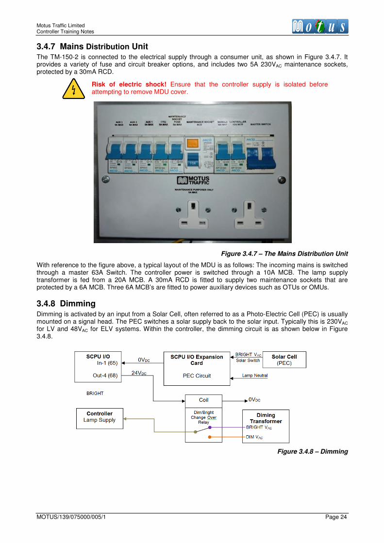
3.4.7 Mains Distribution Unit The TM-150-2 is connected to the electrical supply through a consumer unit, as shown in Figure 3.4.7. It provides a variety of fuse and circuit breaker options, and includes two 5A 230VAC maintenance sockets, protected by a 30mA RCD.
Figure 3.4.7 – The Mains Distribution Unit
With reference to the figure above, a typical layout of the MDU is as follows: The incoming mains is switched through a master 63A Switch. The controller power is switched through a 10A MCB. The lamp supply transformer is fed from a 20A MCB. A 30mA RCD is fitted to supply two maintenance sockets that are protected by a 6A MCB. Three 6A MCB’s are fitted to power auxiliary devices such as OTUs or OMUs.
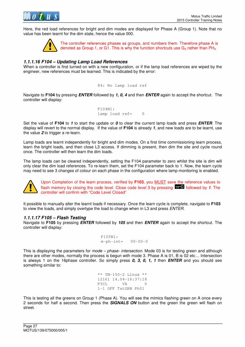
3.4.8 Dimming Dimming is activated by an input from a Solar Cell, often referred to as a Photo-Electric Cell (PEC) is usually mounted on a signal head. The PEC switches a solar supply back to the solar input. Typically this is 230VAC for LV and 48VAC for ELV systems. Within the controller, the dimming circuit is as shown below in Figure 3.4.8.
Figure 3.4.8 – Dimming
Risk of electric shock! Ensure that the controller supply is isolated before attempting to remove MDU cover.

Motus Traffic Limited 2015 Controller Training Notes
Page 25 MOTUS/139/075000/005/1
3.5 Service Functions
3.5.1 User Access Levels There are three levels of user access permissions on the TM-150-2 Linux series of controllers.
1.1.1.7 Level 1 Many of the parameters stored in the controller configuration can be viewed on the controller display panel, or via a laptop or terminal device, without any permissions being set, i.e. when the controller is in code level 1 (L1). This is the default level of access when opening the cabinet door or display panel access flap.
1.1.1.8 Level 2 Some controller parameters can be altered that don’t require the Engineer to verify local access, and they can also be altered via a remote terminal session. These are accessible with Level 2 (L2) access. The access code for L2 is set to 1234 by default, but can be re-programmed on request to any 10 digit number at the request of the customer. Many basic service functions are L2.
1.1.1.9 Level 3 There are many functions in the controller that should only be allowed when the Engineer is on site. These are only accessible with Level 3 (L3) access. L3 access can only be granted to the Engineer when on site, via the LCD display panel or local serial handset connection. It is not accessible via the remote terminal interface; however when L3 access has been granted, Some L3 functions can be operated via the remote interface. All level access permissions will time out after 15 minutes of inactivity, thus preventing the controller from being accidentally left in L3 access mode for a long period of time when the Engineer departs site. The code for L3 is 5678 by default, and as with L2, it can be reprogrammed on request to any 10 digit number.
1.1.1.10 Higher Access Levels The higher access levels defined in TR2500A are Level 4 and Level 5. Level 4 functions and parameters cannot be modified in the existing configuration via Levels 1, 2 or 3. They require a new configuration to be uploaded to the controller. L5 relates to the firmware operation and can only be altered by the design authority and with permission from type approval authority.
1.1.1.11 Accessing L2 or L3 To gain L2 user access permissions, first key in the security code via the front panel follow these steps:
1. Press followed by 001. The controller will display:
1=L1 - 2=L2 - 3=L3
Current Level: 1
New Level: _
2. Press 2 to select L2 then press ENTER to accept The controller will display:
CODE level-2 = XXXX
3. Enter the four digit L2 security code (default 1234) and press the ENTER button to accept. The controller will display:
CODE level-2 Opened
To gain L3 user access permissions, follow the instructions above, selecting 3, and keying in the 4 digit security code for L3. The default is 5678.

Motus Traffic Limited Controller Training Notes
MOTUS/139/075000/005/1 Page 26
3.5.2 Basic Service Functions The built-in service functions are accessible through the Front Panel. Press the MENU button to open the service and programming menu. Select the Service Menu. Most of the functions require L2 user access. Date and Time require L3 access. In this section six of the basic service functions are explained in detail. They are:
F100 View time and date F101 Setting the time F102 Setting the date F103 Viewing lamp reference loads F104 Learning lamp reference loads F105 Flash testing
1.1.1.12 F100 – View time and date Press MENU and scroll down to Service Functions. Press ENTER to accept this shortcut. Select Function 100, to view the current time and date. The time and date is shown:
Date: Time:
2011-04-13 16:30:27
To leave the screen and return to the default status display, press the ESC button.
1.1.1.13 F101 – Set time An alternative to navigating through service menu to get to the required function is to use the QUICK JUMP function shortcut. F101 can be found by simply pressing ENTER followed by 1, 0, 1 then ENTER again to accept the shortcut. The following screen will be displayed:
F101N1:
T. h-m-s= 16-35-12
The time is set by keying in the time in 24 hour format, hh-mm-ss. When ENTER is pressed after keying in the time, the clock starts up again. L3 access is required. To leave the screen and return to the default status display, press the ESC button.
1.1.1.14 F102 – Set date Navigate to F102 by pressing ENTER followed by 1, 0, 2 then ENTER again to accept the shortcut.
F102N1:
D. y-m-d=2011-04-13
The date is set by keying in the date in dd-mm-yy format. The week day is automatically set. The change is accepted when the ENTER button is pressed. L3 access is required. To leave the screen and return to the default status display, press the ESC button.
1.1.1.15 F103 – Lamp Load References Navigate to F103 by pressing ENTER followed by 1, 0, 3 and then ENTER again to accept the shortcut. Each phase has 4 bright and 4 dim lamp load references; Red, Amber, Green and Aux. These values are used as standard of reference for the lamp load error levels 1 and 2. The references are generated by service-function F104 and are measured in Watts. Aux is not used and will always display a reference value of 000. The references can be shown or changed manually by this function. A new reference value will be generated if F104 is reset (see next paragraph). L3 access is required. The lamp loads are displayed in the format:
F103G1N1:
Red load ref=042-000
Motus Traffic Limited 2015 Controller Training Notes
Page 27 MOTUS/139/075000/005/1
Here, the red load references for bright and dim modes are displayed for Phase A (Group 1). Note that no value has been learnt for the dim state, hence the value 000.
1.1.1.16 F104 – Updating Lamp Load References When a controller is first turned on with a new configuration, or if the lamp load references are wiped by the engineer, new references must be learned. This is indicated by the error:
84: No lamp load ref
Navigate to F104 by pressing ENTER followed by 1, 0, 4 and then ENTER again to accept the shortcut. The controller will display:
F104N1:
lamp load ref= 0
Set the value of F104 to 1 to start the update or 0 to clear the current lamp loads and press ENTER. The display will revert to the normal display. If the value of F104 is already 1, and new loads are to be learnt, use the value 2 to trigger a re-learn. Lamp loads are learnt independently for bright and dim modes. On a first time commissioning learn process, learn the bright loads, and then close L3 access. If dimming is present, then dim the site and cycle round once. The controller will then learn the dim loads. The lamp loads can be cleared independently, setting the F104 parameter to zero whilst the site is dim will only clear the dim load references. To re-learn them, set the F104 parameter back to 1. Now, the learn cycle may need to see 3 changes of colour on each phase in the configuration where lamp monitoring is enabled. It possible to manually alter the learnt loads if necessary. Once the learn cycle is complete, navigate to F103 to view the loads, and simply overtype the load to change when in L3 and press ENTER.
1.1.1.17 F105 – Flash Testing Navigate to F105 by pressing ENTER followed by 105 and then ENTER again to accept the shortcut. The controller will display:
F105N1:
m-ph-int= 00-00-0
This is displaying the parameters for mode – phase- intersection. Mode 03 is for testing green and although there are other modes, normally the process is begun with mode 3. Phase A is 01, B is 02 etc… Intersection is always 1 on the 16phase controller. So simply press 0, 3, 0, 1, 1 then ENTER and you should see something similar to:
** TM-150-2 Linux **
12161 14.04-16:37:18
P3CL VA 0
1-1 OFF TstGRN Ph01
This is testing all the greens on Group 1 (Phase A). You will see the mimics flashing green on A once every 2 seconds for half a second. Then press the SIGNALS ON button and the green the green will flash on street.
The controller references phases as groups, and numbers them. Therefore phase A is denoted as Group 1, or G1. This is why the function shortcuts use GX rather than PHX
Upon Completion of the learn process, verified by F103, you MUST save the reference values to
flash memory by closing the code level. Close code level 3 by pressing followed by 1. The controller will confirm with “Code Level Closed”

Motus Traffic Limited Controller Training Notes
MOTUS/139/075000/005/1 Page 28
To change the phase, press down or up to cycle the phases (1 – 16 or A – P). So if the down arrow is pressed once, it would change to Ph02 (Phase B) green. To change the colour simply press the right arrow. Pressing the right arrow steps through the sequence of modes given below. The sequence (when starting at mode 3 green) is 03 Grn Tst Green test
04 Red Tst Red test
05 Amb Tst Amber test
06 R2 Test Aux Red test – Not used.
01 Tst All 01 Test All colours starting at Phase A – Not normally used.
02 Tst RAG Test all colours on the current phase being flashed – Not normally used
3.6 Status Monitoring The front panel has a status button which can be used to monitor the real-time state of various components of the controller. For this application the most useful ones are Detector Logics, Inputs, and Outputs. The status monitor presents a multiple status view, of 16 bits.
3.6.1 Detector Logic Status To examine the detector logic status, follow the sequence below. 1. Press the STATUS button 2. Scroll down to the “02 Multiple Status” option and press ENTER 3. Select the “02 DET Logic” option and press ENTER 4. Choose a starting logic (Goto Index default is 01) and press ENTER 5. The controller will display something like:
02 DET logic
001:1011000000000000
The logics are processed so if an input to a detector logic is inverted, the input would have to be “off” for it to register as a logic 1. The inputs will change in real time. To go back to the normal display press ESC.
3.6.2 Input Status The standard digital inputs into the controller start at 101 for input 01, up to 164 for input 64. The four inputs onto the safety CPU are 65 – 68. To examine multiple input status follow the sequence below: 1. Press the STATUS button 2. Scroll down to the “02 Multiple Status” option and press ENTER 3. Select the “04 INPUT” option and press ENTER 4. Choose the starting input 101 (Goto Index default is 001 not 101) and press ENTER 5. The controller will display something like:
04 INPUT
101:1100001111000000
3.6.3 Output Status The standard digital outputs from the controller can be monitored from the status window. The outputs start at 1 and go up to 128. The four outputs from the safety CPU are 65 – 68. To examine multiple output status follow the sequence below: 1. Press the STATUS button 2. Scroll down to the “02 Multiple Status” option and press ENTER 3. Select the “07 OUTPUT” option and press ENTER 4. Choose the starting output (Goto Index default is 01) and press ENTER
The physical controller inputs can be seen on the yellow led mimics on the I/O Cards. Remember on the status panel 101 is input 1, 164 is input 64.

Motus Traffic Limited 2015 Controller Training Notes
Page 29 MOTUS/139/075000/005/1
5. The controller will display something like: 07 OUTPUT
001:1100001111000000
3.7 Fault Diagnostics
3.7.1 Overview The TM-150-2 is equipped with diagnostic check facilities to identify and log all detected fault conditions. Access to this information is achieved through the control panel, web pages or handset terminal and is also indicated by an LED on the Safety CPU card. When healthy, this LED will flash once per second. When a fault condition arises it will remain steady ON.
Active faults and errors are saved as time-stamped records in an error register so that a chronology of events can be retrieved for inspection. The register is a rolling list that can store 64 entries before the oldest entry is overwritten. A fault record can be automatically removed from the error register when the fault condition is rectified without user intervention. The error register can also be cleared manually.
The TM-150-2 records each fault into one of three different logs:
• Detector error log.
• Lamp error log.
• General error log.
Each log can store 96 errors. An error is prefixed by ‘+’, a major fault by ‘*’ and a self-clearing error by ‘-’.
In addition to the three error logs, there are more generalised chronological records comprising:
• Event log.
• Plan change log.
Each of these logs can store 96 entries. The logs can be also be retrieved and exported from the integrated web interface.
3.7.2 Response to Major Faults and Fatal Errors In response to major faults and fatal errors, the TM-150-2 changes to the failure mode. In this state, it switches the traffic signals to OFF or by special request, switches them to flashing amber. The status of the LEDs on the lamp switch card and the internal status of the signal phases are frozen. The error LED on the Safety CPU card is illuminated and error information is displayed similar to that shown below, where the controller has detected a green conflict caused by phase C.
** TM-150-2 Linux **
12157 10.01-09:13:22
FATAL ERROR I1
Conflict Ph03
The I1 referenced relates to the label for the Safety CPU, since the firmware can support controller with two
Safety CPUs. The second CPU would be referenced as I2. This is not normally used in the UK.
Internally, the TM-150-2 continues to operate as before, but the error state persists until it is reset by clearing the current error register (after gaining L3 access). After this the TM-150-2 changes to the start-up mode.
3.7.3 Response to Minor Faults and Errors In response to minor faults and errors, the error LED on the Safety CPU card is illuminated and the TM-150-2 continues to operate as before. To gain more information about the error, press the ERROR button and select F200 Current errors, as shown below.
** TM-150-2 Linux **
12157 12.01-12:16:25
P1CL UTC-Fr 0 1-1 ON_ERR S1/S2 22
2011-01-13 12:16:25
+ 84-000-000 01/01
No lampload ref
Press ERROR + F200 Current errors

Motus Traffic Limited Controller Training Notes
MOTUS/139/075000/005/1 Page 30
The fields of the displayed information are explained in Table 3.7.3.
Table 3.7.3 Example Error Information
Field / Parameter Description
2015-01-13 Date when error occurred in YYYY-MM-DD format.
13:12:42 Time when error occurred in hh:mm:ss format.
+84-000-000 Error code. A ‘+’ prefix indicates that the error has just occurred.
01/01: Error number / total current errors.
<text> Error description.
3.7.4 Displaying Error Codes To view a list of current error codes, press the ERROR button and select F200 Current errors. Use the
↑↑↑↑ or ↓↓↓↓ buttons to step through the circular list.
1.1.1.18 Selection, Viewing and Clearing
To access the information logs, first press the LOG button. The log functions will be displayed as shown below.
>F202 Det error log
F203 Lamp error log
F204 Error log
F205 Event log
Scrolling up or down by using the ↑↑↑↑ or ↓↓↓↓ buttons moves the cursor through the circular list. To view the details of the selected log (i.e. F202 to F206), press the ENTER button. To clear the logs, select F207 in the
same way.
3.7.5 Example of Interrogating an Error The most common error is a detector fault. Examining the logs will inform as to which detector logic has stuck, whether it is stuck ON or OFF and when this occurred. The name of the detector can be found by noting the Detector Logic Number, then navigating to Function 12 to check the name of the Detector Logic. An example is given below. 1. The following screen is encountered:
** TM-150-2 Linux **
18864 04.05-23:00:45
P1CL VA 0
1-1 ON_ERR S1/S2 10
2. Press ERROR and the controller will display:
>F200 Current errors
F201 Reset errors
3. Press ENTER to view current errors: 2015-05-04 23:00:50
+ 41-07-000
Det DL07 on
This shows that Detector Logic 07 has stuck ON due to the input to that logic being high for the prescribed time as set by the configuration. Follow the instructions below to find out what the input that is stuck actually is. 4. Press ESC to return to the main screen. Next press ENTER. The controller will display:
QUICK JUMP
FUNCTION no. 000

Motus Traffic Limited 2015 Controller Training Notes
Page 31 MOTUS/139/075000/005/1
5. Enter 0,1, 2 to select Function 12, Detector Logics and press ENTER to accept. The controller will display the first detector logic on the display:
F12D1N0:
AMVD1
This is the first input in the controller, which is the MVD for A Phase. The function code in the top left corner, F12D1N0 means Function12, Detector Logic 1, Parameter 0. Parameter 0 for a Detector Logic is the name label. 6. To find out what Detector Logic 07 is, the currently displayed parameter needs to change from D1 to D07.
This can be done by pressing the down arrow until the F12D07N0 parameter is displayed, or by pressing the MENU button to do a short cut. When MENU is pressed the controller will display:
F12D1N0:
Goto index= 00-001-
^
The 00 is parameter 0, the 001 is the Detector Logic number. Type 0, 0, then 0, 0, 7 to change the index to 00-007. Press ENTER. The controller will display:
F12D07N0:
COCD1
So the stuck detector is the first On-Crossing detector. It has stuck high, indicating a fault with the input to the controller. 7. In order to see what the physical input is associated with Detector Logic 07, simply press ENTER twice to display the input parameter:
F12D07N2:
Input= 01-003-107
This shows that input 107 is the first on-crossing detector. So the first thing to do would be to unwire input 07 from the terminal block and test it by shorting the input to 0VDC and checking whether the input changes state both on the I/O card orange LED and by using the STATUS menu to look at the input status: STATUS -> 02 MULTIPLE STATUS -> 04 INPUT -> Goto index = 107. This will show input 107 as the first input on the left:
02 DET logic
001:1000000000000000
Input 107 status will be indicated by a 0 or 1. If this is proven to show the input working, check the MVD socket wiring, cap-top wiring, connection to the On-Crossing or the unit itself.

Motus Traffic Limited Controller Training Notes
MOTUS/139/075000/005/1 Page 32
3.8 Handset Commands
3.8.1 Set Up The terminal is a standard powered 25pin RS232 port. Connection can be made by laptop or other terminal device such as a TechTerm or Oyster Terminal. The default connection settings are configured using the web admin pages. The default comp port settings are. 1200 baud, 7data bits, Even parity, 1 stop bit and no flow control. The configuration text is given below:
name=/dev/ttyS0
speed=1200
opt=7-E-1
Figure 3.8.1 shows the web admin page. If settings need to be changed, they are changed here.
Figure 3.8.1 – Configuration Page for Motus Terminal Interface To change the settings, over-type the current settings and click on the Update configuration button. Next, click the Stop button followed by the Restart button to accept the new settings.
3.8.2 Syntax and Formatting When connected to the terminal, pressing enter should return:
>
*S
Currently there are several reply codes indicating different states. They are listed below.
Table 3.8.2 Motus Terminal Interface Syntax Replies
Reply Meaning
*S Syntax Error, text not recognized
*V Value Error, the entered value did not match format expected
*R Range Error, the entered value was out of range of acceptable values
*A Authorisation Error, command needs higher access level
There is no requirement for upper or lower case, either case is acceptable, the terminal will use upper case. If a mistake is made, it can be corrected before the ENTER or RETURN key is pressed.
Motus Traffic Limited 2015 Controller Training Notes
Page 33 MOTUS/139/075000/005/1
1.1.1.19 Displaying a Parameter When displaying a parameter the controller will follow the mnemonic with a colon, then the value. For example Minimum Green for Phase A would return:
> MIN C
MIN C: 6
>
1.1.1.20 Scrolling a Parameter When displaying a parameter, such as MIN C, pressing the + or – keys will scroll to the next parameter for example pressing – will display MIN B, and pressing + will display MIN D.
1.1.1.21 Changing a Parameter Value Currently when a parameter such as MIN A is displayed, the mnemonic will have to be re-typed, followed by the parameter e.g. phase letter, followed by = and the value. For example to change the value of MAX A, the alternative Maximum Green Set A value for phase A, the user would need to type MAX A=30. It is anticipated that in a future update to the terminal the ability to press = after the last returned parameter will automatically all the user to try to set the value. The terminal will accept or reject the change subject to value and permission level.
1.1.1.22 WID Command It is important to be able to restrict the terminal to a certain length of characters for correct display on small terminal devices. The WID command can set the number of characters displayed before a Carriage Return. The range is 14 to 80 characters. The default is 20. This is particularly important to Pass-Through mode as many of the replies are quite long.
1.1.1.23 Changing between Motus Terminal Mode and Pass-Through Mode The default mode of the terminal is Motus Terminal Mode, using the new mnemonics to access controller parameters. The legacy terminal remains available as a pass through mode to ensure that parameters not yet defined in the new terminal can still be accessed. This is called Pass through mode. To change between the two terminals, press the # key. The controller will indicate what mode has been made available before the first prompt.
1.1.1.24 Escape Character in Pass-Through Mode The legacy controller terminal requires the user to escape (ESC) out of a viewed parameter in order to view something else. Many UK systems don’t correctly pass the ESC character to the terminal, so the @ symbol was chosen as a replacement.
3.8.3 Level Access Commands The Command LEV is used to change access levels in the controller. Level 3 access is only granted when the controller display panel has Level 3 access, to ensure that there is someone on site when the Terminal is granted L3 access.
Table 3.8.3 – Access Levels
Command Controller Access Level Reply
Meaning
LEV=1 LEV:1 Closed code levels
LEV=2 LEV:2 L2 access granted
LEV=3 LEV:2 Display Not in L3, L2 access granted
LEV=3 LEV:3 L3 access granted (display in L3)
Motus Traffic Limited Controller Training Notes
MOTUS/139/075000/005/1 Page 34
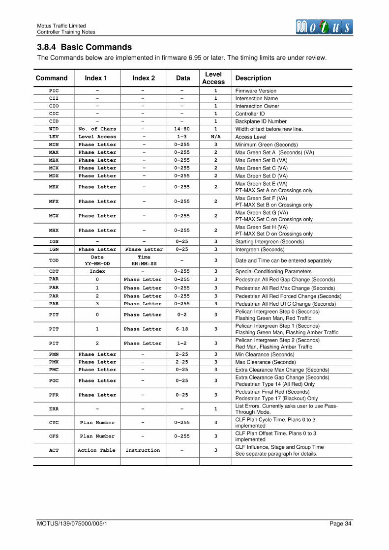
3.8.4 Basic Commands The Commands below are implemented in firmware 6.95 or later. The timing limits are under review.
Command Index 1 Index 2 Data Level
Access Description
PIC - - - 1 Firmware Version
CII - - - 1 Intersection Name
CIO - - - 1 Intersection Owner
CIC - - - 1 Controller ID
CID - - - 1 Backplane ID Number
WID No. of Chars - 14-80 1 Width of text before new line.
LEV Level Access - 1-3 N/A Access Level
MIN Phase Letter - 0-255 3 Minimum Green (Seconds)
MAX Phase Letter - 0-255 2 Max Green Set A (Seconds) (VA)
MBX Phase Letter - 0-255 2 Max Green Set B (VA)
MCX Phase Letter - 0-255 2 Max Green Set C (VA)
MDX Phase Letter - 0-255 2 Max Green Set D (VA)
MEX Phase Letter - 0-255 2 Max Green Set E (VA)
PT-MAX Set A on Crossings only
MFX Phase Letter - 0-255 2 Max Green Set F (VA)
PT-MAX Set B on Crossings only
MGX Phase Letter - 0-255 2 Max Green Set G (VA)
PT-MAX Set C on Crossings only
MHX Phase Letter - 0-255 2 Max Green Set H (VA)
PT-MAX Set D on Crossings only
IGS - - 0-25 3 Starting Intergreen (Seconds)
IGN Phase Letter Phase Letter 0-25 3 Intergreen (Seconds)
TOD Date
YY-MM-DD
Time
HH:MM:SS - 3 Date and Time can be entered separately
CDT Index - 0-255 3 Special Conditioning Parameters
PAR 0 Phase Letter 0-255 3 Pedestrian All Red Gap Change (Seconds)
PAR 1 Phase Letter 0-255 3 Pedestrian All Red Max Change (Seconds)
PAR 2 Phase Letter 0-255 3 Pedestrian All Red Forced Change (Seconds)
PAR 3 Phase Letter 0-255 3 Pedestrian All Red UTC Change (Seconds)
PIT 0 Phase Letter 0-2 3 Pelican Intergreen Step 0 (Seconds)
Flashing Green Man, Red Traffic
PIT 1 Phase Letter 6-18 3 Pelican Intergreen Step 1 (Seconds)
Flashing Green Man, Flashing Amber Traffic
PIT 2 Phase Letter 1-2 3 Pelican Intergreen Step 2 (Seconds)
Red Man, Flashing Amber Traffic
PMN Phase Letter - 2-25 3 Min Clearance (Seconds)
PMX Phase Letter - 2-25 3 Max Clearance (Seconds)
PMC Phase Letter - 0-25 3 Extra Clearance Max Change (Seconds)
PGC Phase Letter - 0-25 3 Extra Clearance Gap Change (Seconds)
Pedestrian Type 14 (All Red) Only
PFR Phase Letter - 0-25 3 Pedestrian Final Red (Seconds)
Pedestrian Type 17 (Blackout) Only
ERR - - - 1 List Errors. Currently asks user to use Pass-Through Mode.
CYC Plan Number - 0-255 3 CLF Plan Cycle Time. Plans 0 to 3 implemented
OFS Plan Number - 0-255 3 CLF Plan Offset Time. Plans 0 to 3 implemented
ACT Action Table Instruction - 3 CLF Influence, Stage and Group Time
See separate paragraph for details.
Motus Traffic Limited 2015 Controller Training Notes
Page 35 MOTUS/139/075000/005/1
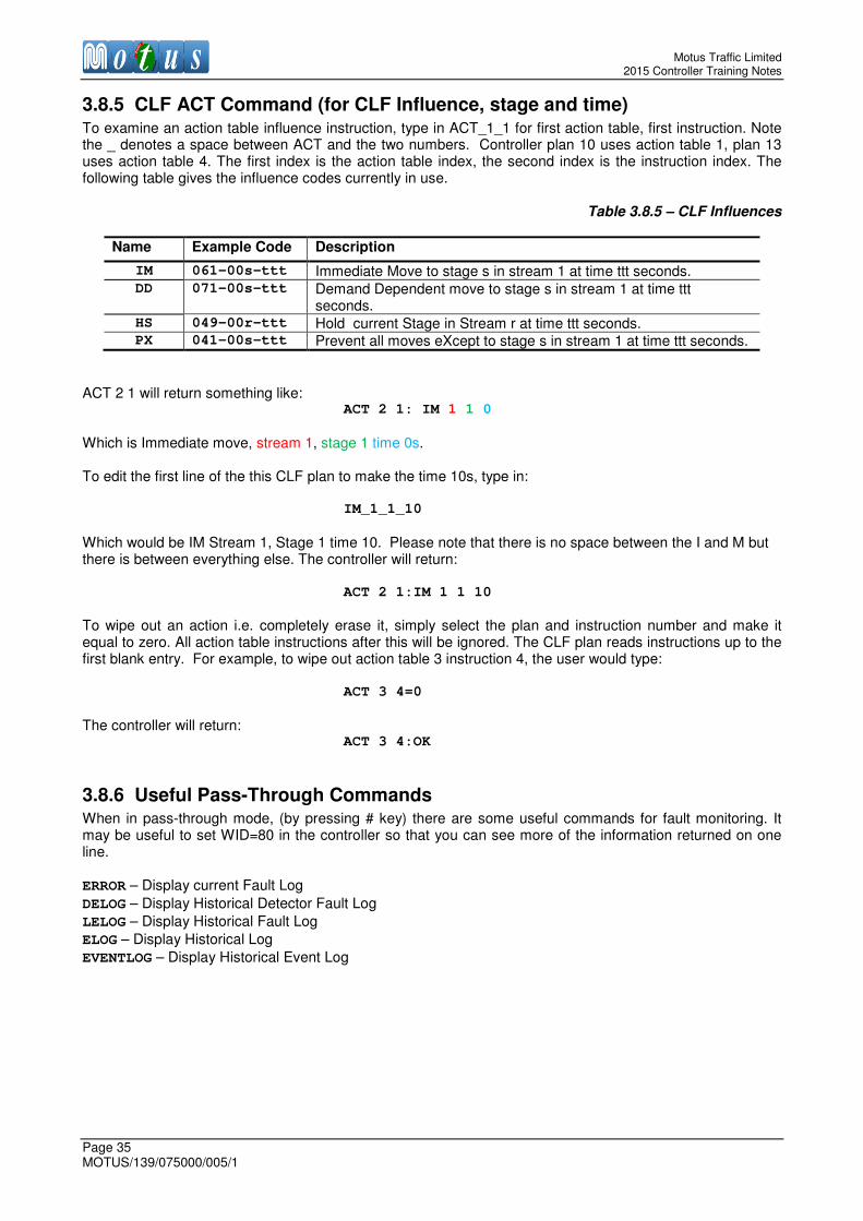
3.8.5 CLF ACT Command (for CLF Influence, stage and time) To examine an action table influence instruction, type in ACT_1_1 for first action table, first instruction. Note the _ denotes a space between ACT and the two numbers. Controller plan 10 uses action table 1, plan 13 uses action table 4. The first index is the action table index, the second index is the instruction index. The following table gives the influence codes currently in use.
Table 3.8.5 – CLF Influences
Name Example Code Description
IM 061-00s-ttt Immediate Move to stage s in stream 1 at time ttt seconds. DD 071-00s-ttt Demand Dependent move to stage s in stream 1 at time ttt
seconds. HS 049-00r-ttt Hold current Stage in Stream r at time ttt seconds. PX 041-00s-ttt Prevent all moves eXcept to stage s in stream 1 at time ttt seconds.
ACT 2 1 will return something like:
ACT 2 1: IM 1 1 0
Which is Immediate move, stream 1, stage 1 time 0s. To edit the first line of the this CLF plan to make the time 10s, type in:
IM_1_1_10
Which would be IM Stream 1, Stage 1 time 10. Please note that there is no space between the I and M but there is between everything else. The controller will return:
ACT 2 1:IM 1 1 10
To wipe out an action i.e. completely erase it, simply select the plan and instruction number and make it equal to zero. All action table instructions after this will be ignored. The CLF plan reads instructions up to the first blank entry. For example, to wipe out action table 3 instruction 4, the user would type:
ACT 3 4=0
The controller will return:
ACT 3 4:OK
3.8.6 Useful Pass-Through Commands When in pass-through mode, (by pressing # key) there are some useful commands for fault monitoring. It may be useful to set WID=80 in the controller so that you can see more of the information returned on one line. ERROR – Display current Fault Log
DELOG – Display Historical Detector Fault Log
LELOG – Display Historical Fault Log
ELOG – Display Historical Log
EVENTLOG – Display Historical Event Log

Motus Traffic Limited Controller Training Notes
MOTUS/139/075000/005/1 Page 36
4 TM-150-2 Integrated Web Interface In this chapter:
Logging In
Overview
Front Panel
Log Menus
Traffic Analysis
Management
Logging Out
4.1 Logging In The integrated web interface is accessed via a login page. The URL depends upon the type of connection to the TM-150-2 controller.
4.1.1 Physical Connection When using a physical connection via the Ethernet port, you connect to the web-server using an URL-specified IP address. The default address is http://192.168.0.75.
4.1.2 Remote Connection If you are using the Motus Traffic Controller VPN (Virtual Private Network) to access the controller through the 3G Mobile Phone Network, this IP address will be different. Please check the IP address that you were provided with.
4.1.3 Login Page Whichever way you access the controller the login page will be presented, shown in Figure .
Figure 4.1.3 Login Page (Default username admin and password contact Motus)
Motus recommends Google Chrome or Firefox Browsers for best compatibility with the web pages

Motus Traffic Limited 2015 Controller Training Notes
Page 37 MOTUS/139/075000/005/1
4.2 Overview Tab The Overview tab is shown in Figure 4.1.4.1. It provides a composite view including a map with real-time information about the signal phases, a virtual clone of the text-based LCD on the control panel and an error log window.
Figure 4.1.4.1 Overview Tab Display
The overview page is designed to present as much useful information as possible without appearing to be cluttered. The LCD screen in the control window is updated approximately once per second, providing real time information about the controller status. The police function keys in the control window are read-only, and you can see which buttons are active as they are coloured blue, whereas the inactive buttons are grey. Just below the top menu tabs, the name of the intersection and the owner of the configuration are displayed for reference. There is an optional map window, which can display a site layout map, with coloured icons showing the real time status of the signals. If the signals are off, the map will display but there will be no icons visible. Below the map display is a space for current errors to be displayed. This error log can contain up to 64 entries. A scroll bar will appear if necessary. The log can be refreshed by pressing the Reload Log button, or exported to a .txt file for archiving.
Underneath the real time LCD display is a button which can bring up a graphical representation of the control panel, shown in Figure 4.1.4.2 The black buttons can be pressed to manipulate the display to show the user various parameters. The mode buttons and signal ON/OFF buttons are greyed out because they are inactive over the remote network.
Figure 4.1.4.2 Control Panel Display

Motus Traffic Limited Controller Training Notes
MOTUS/139/075000/005/1 Page 38
4.3 Log Tab Click on the Log tab from the top menu to open the log display, shown in Figure 4.1.5 At the top of the page there are two sub menus:
• Log Viewer
• Temp & Mains Log At the bottom of the page there are tabs that select the detailed logs:
• Detector log
• Event log
• Lamp log
• Plan log Click on the small arrow to reload the log. To the right of the log selection tabs, there is an export tab. Hovering over the Export button will reveal some text that explains how to export the data to another program.
Figure 4.1.5 Log Viewer Tab Display
4.4 Traffic Analysis Tab The Traffic Analysis tab contains information about the lamp status, phase timings and traffic count.
4.4.1 Lamp Status Tab Click on the Traffic Analysis tab to give you a page with three tabs. The first of these is Lamp Status, shown in Figure 4.4.1.
Figure 4.4.1 Lamp Status Tab Display
At the top of the Lamp Status page, there is a summary of the controller plan and lamp status. Underneath this textural information, all monitored phases are displayed. For each phase it is possible to view load levels

Motus Traffic Limited 2015 Controller Training Notes
Page 39 MOTUS/139/075000/005/1
and reference levels for lamp monitoring. There is a slight delay from what is happening on street to what is displayed here, of around one second.
4.4.2 Stripes Tab The second tab under the Traffic Analysis tab is called Stripes. It is shown in Figure 4.4.2.1
Figure 4.4.2.1 Stripes Tab Display
This shows a real-time view of selected phases and detectors. At the top of the page there are various options. The first is the point in time to start viewing the signal data with stripes. The default is live view, but it is possible to set the start time to the last fatal error, or a given time in the past. A zoom level can be selected (the default is x1). The stripe length (x –co-ordinate on the graph) can be changed here, the default being 60s. One of the most useful features is the option to select the type of output viewed through stripes. There are two options: The default is signal logic “S” categorising the signal phase into min, max, past-end green. If a simpler view is required, tick the “O” check box which will display the signal phase output i.e. red, amber, green, starting amber, or Off. Along the stripe itself the time in seconds that a particular state has been maintained is written. It is possible to view both types of stripe at the same time by checking both boxes. Using the button brings a window up to select the displayed signal phases, and detector logics. This is shown in Figure 4.4.2.2. The selected detector logics are displayed with an active logic coloured blue, and inactive coloured grey.
Figure 4.4.2.2 Select Stripes Detail Window

Motus Traffic Limited Controller Training Notes
MOTUS/139/075000/005/1 Page 40
4.4.3 Traffic Count Tab The third tab under the Traffic Analysis tab is called Traffic Count. It is shown in Figure 4.4.3.
Figure 4.4.3 Traffic Count Tab Display
With this analytical tool, counters can be assigned to detector logic rules, so that each time the input to that detector logic rule is activated, the controller stores the time of the event. This allows the user to monitor specific detectors on a site for analysis later. This can be useful for ascertaining how busy a particular traffic approach is, or working out whether the selected DFM off times on a pedestrian crossing are long enough, for example, by monitoring the use of the crossing over a weekend. The detector counting facility is built into the controller, and is very simple to set up. The Traffic Count tab will open a page where you can select the following:
• The start and stop time.
• Which counters are displayed.
• The time resolution: 1, 5, 10, 15, 30 or 60 minutes. Press the Generate button to draw the graph. It is possible remove a counter from the graph by de-selecting it from the tick box below.
4.5 Management Tab The Management tab is split into three sub tabs, Configuration, My Account and Users.

Motus Traffic Limited 2015 Controller Training Notes
Page 41 MOTUS/139/075000/005/1
4.5.1 Configuration Tab The first tab is Configuration, shown in Figure 4.5.1, in which several of the remote monitoring features are set up.
Figure 4.5.1.1 Configuration Tab Display
Configuration Upload
Configuration upload modifies the map overview that is present on the front page. There are two uploadable files which configure this feature – the map configuration script and the map image file. The map configuration script is a text file where the location and orientation of the arrows representing the signal states are set up. An example script is given below. Group 1
Arrow: pos(418,205) rotate(180) scale(40)
Arrow: pos(300,175) rotate(0) scale(40)
Group 2
Arrow: pos(370,228) rotate(90) scale(25) only_on(red)
Arrow: pos(370,228) rotate(90) scale(25) not_on(red)
Arrow: pos(340,150) rotate(270) scale(25) only_on(red)
Arrow: pos(340,150) rotate(270) scale(25) not_on(red)
Arrow: pos(340,228) rotate(90) scale(25) only_on(red)
Arrow: pos(340,228) rotate(90) scale(25) not_on(red)
Arrow: pos(370,150) rotate(270) scale(25) only_on(red)
Arrow: pos(370,150) rotate(270) scale(25) not_on(red)
// MAP_IMG: ../applets/map-image.png
The co-ordinate system origin is the top left corner. The image size is 640 pixels by 400. The icons are arranged by phase, referred to as Groups in the configuration script. So for Phase A, there are two arrows, whose x and y co-ordinates are given, along with their rotation. 0 degrees is pointing left to right. The scale parameter refers to the size of the icon. Because phase B is a pedestrian icon, there are two icons for each arrow displayed, one only displayed when the phase is red, and one when the phase is not on red.

Motus Traffic Limited Controller Training Notes
MOTUS/139/075000/005/1 Page 42
Figure 4.5.1.2 shows the results of the configuration script given on the previous page. Phase A is Green, and the Pedestrians are on Red Man. Any image can be used as the background, such as a site layout drawing, a map extract or a custom bitmap. The size should be scaled to 640 x 400 pixels, but it shall be automatically scaled to fit. The file format must be either JPG or PNG. Try to keep the file size as small as possible.
Figure 4.5.1.2 Example of The Overview Map With Icons
Configuration Download
Configuration Download saves the two configuration files for generating the Map Overview to an external storage device. In the future it will also be possible to download the configuration via this page as well. To download the files, simply hover the mouse icon over the file and click the link, where a save dialog box will be displayed.
Supported WXCom Clients
At present there are two remote systems that can access various data from the controller through a unique communications protocol. WXCom is not widely used and is not discussed in this manual. Some authorities are using a common database system called Cutlas, which the controller supports through its Cutlas WXCom client. This allows real-time fault data to be passed from the controller to the Cutlas system, for automatic fault monitoring and allocation to the engineers on call.
The status of the client is shown in the window. If the client is disabled there will be no information displayed for System ID or Setup PIN. The status will show as Disabled. To enable the interface, click on the Enable button in the status window. When this occurs, a number will appear in the setup PIN column. This number should be used by the operator when editing the ini file of the Motus Cutlas Adapter supplied with Cutlas. The IP address of the controller along with a system ID code and group key are also required, and will be provided by Motus on request. The Cutlas system will then handshake with the remote controller and the status window will look similar to that of Figure 10.9.
4.5.2 My Account Tab The My Account tab allows the user to modify their user details via the dialog box shown in Figure 4.5.2
Figure 4.5.2 Change Information Dialog Box
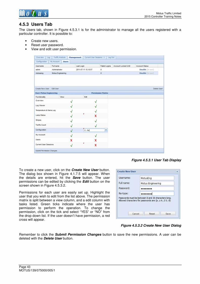
Motus Traffic Limited 2015 Controller Training Notes
Page 43 MOTUS/139/075000/005/1
4.5.3 Users Tab The Users tab, shown in Figure 4.5.3.1 is for the administrator to manage all the users registered with a particular controller. It is possible to:
• Create new users.
• Reset user password.
• View and edit user permission.
Figure 4.5.3.1 User Tab Display
To create a new user, click on the Create New User button. The dialog box shown in Figure 4.1.7.5 will appear. When the details are entered, hit the Save button. The user permissions can be edited by clicking the Edit button on the screen shown in Figure 4.5.3.2.
Permissions for each user are easily set up. Highlight the user that you wish to edit from the list above. The permission matrix is split between a view column, and a edit column with tasks listed. Green ticks indicate where the user has permission to perform the operation. To change the permission, click on the tick and select “YES” or “NO” from the drop down list. If the user doesn’t have permission, a red cross will appear.
Figure 4.5.3.2 Create New User Dialog
Remember to click the Submit Permission Changes button to save the new permissions. A user can be deleted with the Delete User button.

Motus Traffic Limited Controller Training Notes
MOTUS/139/075000/005/1 Page 44
4.6 Current User Sessions Tab In the Current User Sessions tab, shown in Figure 4.6.1, all users currently logged on to the controller are listed. Users with administrator rights can force other users’ sessions to be closed. Click Terminate in the Session column.
Figure 4.6.1 Current User Sessions Tab Display
4.7 Log Out Tab The Log Out tab is shown in Figure 4.7.1. Simply click on it to end the session. The controller counts down five seconds and then returns to the log in screen.
Figure 4.7.1 Log Out Tab Display
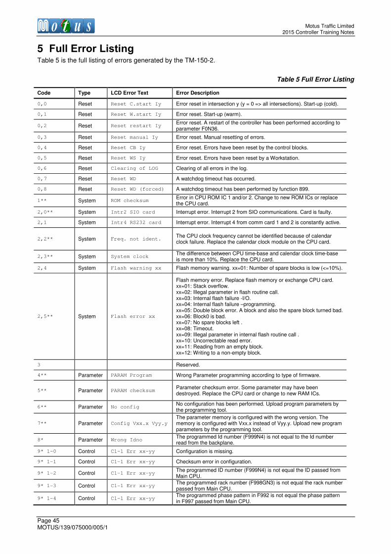
Motus Traffic Limited 2015 Controller Training Notes
Page 45 MOTUS/139/075000/005/1
5 Full Error Listing Table 5 is the full listing of errors generated by the TM-150-2.
Table 5 Full Error Listing
Code Type LCD Error Text Error Description
0,0 Reset Reset C.start Iy Error reset in intersection y (y = 0 => all intersections). Start-up (cold).
0,1 Reset Reset W.start Iy Error reset. Start-up (warm).
0,2 Reset Reset restart Iy Error reset. A restart of the controller has been performed according to parameter F0N36.
0,3 Reset Reset manual Iy Error reset. Manual resetting of errors.
0,4 Reset Reset CB Iy Error reset. Errors have been reset by the control blocks.
0,5 Reset Reset WS Iy Error reset. Errors have been reset by a Workstation.
0,6 Reset Clearing of LOG Clearing of all errors in the log.
0,7 Reset Reset WD A watchdog timeout has occurred.
0,8 Reset Reset WD (forced) A watchdog timeout has been performed by function 899.
1** System ROM checksum Error in CPU ROM IC 1 and/or 2. Change to new ROM ICs or replace the CPU card.
2,0** System Intr2 SIO card Interrupt error. Interrupt 2 from SIO communications. Card is faulty.
2,1 System Intr4 RS232 card Interrupt error. Interrupt 4 from comm card 1 and 2 is constantly active.
2,2** System Freq. not ident. The CPU clock frequency cannot be identified because of calendar clock failure. Replace the calendar clock module on the CPU card.
2,3** System System clock The difference between CPU time-base and calendar clock time-base is more than 10%. Replace the CPU card.
2,4 System Flash warning xx Flash memory warning. xx=01: Number of spare blocks is low (<=10%).
2,5** System Flash error xx
Flash memory error. Replace flash memory or exchange CPU card. xx=01: Stack overflow. xx=02: Illegal parameter in flash routine call. xx=03: Internal flash failure -I/O. xx=04: Internal flash failure –programming. xx=05: Double block error. A block and also the spare block turned bad. xx=06: Block0 is bad. xx=07: No spare blocks left . xx=08: Timeout. xx=09: Illegal parameter in internal flash routine call . xx=10: Uncorrectable read error. xx=11: Reading from an empty block. xx=12: Writing to a non-empty block.
3
Reserved.
4** Parameter PARAM Program Wrong Parameter programming according to type of firmware.
5** Parameter PARAM checksum Parameter checksum error. Some parameter may have been destroyed. Replace the CPU card or change to new RAM ICs.
6** Parameter No config No configuration has been performed. Upload program parameters by the programming tool.
7** Parameter Config Vxx.x Vyy.y
The parameter memory is configured with the wrong version. The memory is configured with Vxx.x instead of Vyy.y. Upload new program parameters by the programming tool.
8* Parameter Wrong Idno The programmed Id number (F999N4) is not equal to the Id number read from the backplane.
9* 1-0 Control C1-1 Err xx-yy Configuration is missing.
9* 1-1 Control C1-1 Err xx-yy Checksum error in configuration.
9* 1-2 Control C1-1 Err xx-yy The programmed ID number (F999N4) is not equal the ID passed from Main CPU.
9* 1-3 Control C1-1 Err xx-yy The programmed rack number (F998GN3) is not equal the rack number passed from Main CPU.
9* 1-4 Control C1-1 Err xx-yy The programmed phase pattern in F992 is not equal the phase pattern in F997 passed from Main CPU.

Motus Traffic Limited Controller Training Notes
MOTUS/139/075000/005/1 Page 46
Code Type LCD Error Text Error Description
9* 2-0 Control C1-1 Err xx-yy Watchdog timeout.
9* 3-0 Control C1-1 Err xx-yy Communication error due to timeout.
9* 3-1 Control C1-1 Err xx-yy Communication error due to wrong message.
9* 3-2 Control C1-1 Err xx-yy Communication error due to wrong checksum.
9* 4-yy Control C1-1 Err xx-yy Phase-card yy (PH) is missing.
9* 5-yy Control C1-1 Err xx-yy Timing error in 100ms message tick from Main CPU. yy = time in ms since last received message.
9* 6-yy Control C1-1 Err xx-yy The CPU load is too heavy. yy = load time. This time must be < 95 ms.
9* 11 Control C1-1 Err xx-yy Mains frequency out of limit according to programming of F993N7 and F993N8.
9* 12 Control C1-1 Err xx-yy Mains supply out of limit according to programming of F993N2 and F993N3.
9* 13 Control C1-1 Err xx-yy Error in 12VDC supply.
9* 14 Control C1-1 Err xx-yy Error in 5VDC supply.
9* 16 Control C1-1 Err xx-yy Error in amber relay. y=0 => relay is off but it should be on, y=1 => relay is on, but it should be off.
9* 17 Control C1-1 Err xx-yy Error in red/green relay. y=0 => relay is off but it should be on, y=1 => relay is on, but it should be off.
9* 20-0 Control C1-1 Err xx-yy Cycle time too short according to programming of F993N12.
9* 20-1 Control C1-1 Err xx-yy Cycle time too long according to programming of F993N13.
9* 20-yy Control C1-1 Err xx-yy Intergreen violation in phase yy.
9* 22-yy Control C1-1 Err xx-yy Minimum time violation in current state in phase yy.
9* 23-yy Control C1-1 Err xx-yy Maximum time violation in current state in phase yy.
9* 24-yy Control C1-1 Err xx-yy Wrong signal sequence in phase yy.
9* 25-yy Control C1-1 Err xx-yy Phase yy is not red when a conflict exists against the phase.
9* 27-yy Control C1-1 Err xx-yy Error in red output answer in phase yy.
9* 28-yy Control C1-1 Err xx-yy Too low load on red output in phase yy according to minimum load programmed in F5GN2.
9* 29-yy Control C1-1 Err xx-yy Too high load on red output in phase yy according to maximum load programmed in F5GN21.
9* 30-yy Control C1-1 Err xx-yy Error in amber output answer in phase yy.
9* 31-yy Control C1-1 Err xx-yy Too low load on amber output in phase yy according to minimum load programmed in F5GN2.
9* 32-yy Control C1-1 Err xx-yy Too high load on amber output in phase yy according to maximum load programmed in F5GN22.
9* 33-yy Control C1-1 Err xx-yy Error in green output answer in phase yy.
9* 34-yy Control C1-1 Err xx-yy Too low load on green output in phase yy according to minimum load programmed in F5GN2.
9* 35-yy Control C1-1 Err xx-yy Too high load on green output in phase yy according to maximum load programmed in F5GN23.
9* 37-yy Control C1-1 Err xx-yy Wrong frequency in flashing amber in phase yy according to programming of F0N16 and F0N17.
9* 38-yy Control C1-1 Err xx-yy Wrong frequency in flashing green in phase yy according to programming of F0N18 and F0N19.
10* 1-0 Control C1-2 Err xx-yy Configuration is missing.
10* 1-1 Control C1-2 Err xx-yy Checksum error in configuration.
10* 1-2 Control C1-2 Err xx-yy The programmed ID number (F999N4) is not equal the ID passed from Main CPU.
10* 1-3 Control C1-2 Err xx-yy The programmed rack number (F998GN3) is not equal the rack number passed from Main CPU.
10* 1-4 Control C1-2 Err xx-yy The programmed phase pattern in F992 is not equal the phase pattern in F997 passed from Main CPU.
10* 2-0 Control C1-2 Err xx-yy Watchdog timeout.
10* 3-0 Control C1-2 Err xx-yy Communication error due to timeout.
10* 3-1 Control C1-2 Err xx-yy Communication error due to wrong message.
10* 3-2 Control C1-2 Err xx-yy Communication error due to wrong checksum.
10* 4-yy Control C1-2 Err xx-yy Phase-card yy (PH) is missing.

Motus Traffic Limited 2015 Controller Training Notes
Page 47 MOTUS/139/075000/005/1
Code Type LCD Error Text Error Description
10* 5-yy Control C1-2 Err xx-yy Timing error in 100ms message tick from Main CPU. yy = time in ms since last received message.
10* 6-yy Control C1-2 Err xx-yy The cpu load is too heavy. yy = load time. This time must be < 95 ms.
10* 11 Control C1-2 Err xx-yy Mains frequency out of limit according to programming of F993N7 and F993N8.
10* 12 Control C1-2 Err xx-yy Mains supply out of limit according to programming of F993N2 and F993N3.
10* 13 Control C1-2 Err xx-yy Error in 12VDC supply.
10* 14 Control C1-2 Err xx-yy Error in 5VDC supply
10* 16 Control C1-2 Err xx-yy Error in amber relay. y=0 => relay is off but it should be on, y=1 => relay is on, but it should be off.
10* 17 Control C1-2 Err xx-yy Error in red/green relay. y=0 => relay is off but it should be on, y=1 => relay is on, but it should be off.
10* 20-0 Control C1-2 Err xx-yy Cycle time too short according to programming of F993N12.
10* 20-1 Control C1-2 Err xx-yy Cycle time too long according to programming of F993N13.
10* 20-yy Control C1-2 Err xx-yy Intergreen violation in phase yy.
10* 22-yy Control C1-2 Err xx-yy Minimum time violation in current state in phase yy.
10* 23-yy Control C1-2 Err xx-yy Maximum time violation in current state in phase yy.
10* 24-yy Control C1-2 Err xx-yy Wrong signal sequence in phase yy.
10* 25-yy Control C1-2 Err xx-yy Phase yy is not red when a conflict exists against the phase.
10* 27-yy Control C1-2 Err xx-yy Error in red output answer in phase yy.
10* 28-yy Control C1-2 Err xx-yy Too low load on red output in phase yy according to minimum load programmed in F5GN2.
10* 29-yy Control C1-2 Err xx-yy Too high load on red output in phase yy according to maximum load programmed in F5GN21.
10* 30-yy Control C1-2 Err xx-yy Error in amber output answer in phase yy
10* 31-yy Control C1-2 Err xx-yy Too low load on amber output in phase yy according to minimum load programmed in F5GN2.
10* 32-yy Control C1-2 Err xx-yy Too high load on amber output in phase yy according to maximum load programmed in F5GN22.
10* 33-yy Control C1-2 Err xx-yy Error in green output answer in phase yy.
10* 34-yy Control C1-2 Err xx-yy Too low load on green output in phase yy according to minimum load programmed in F5GN2.
10* 35-yy Control C1-2 Err xx-yy Too high load on green output in phase yy according to maximum load programmed in F5GN23.
10* 37-yy Control C1-2 Err xx-yy Wrong frequency in flashing amber in phase yy according to programming of F0N16 and F0N17.
10* 38-yy Control C1-2 Err xx-yy Wrong frequency in flashing green in phase yy according to programming of F0N18 and F0N19.
11* 1-0 Control C2-1 Err xx-yy Configuration is missing.
11* 1-1 Control C2-1 Err xx-yy Checksum error in configuration.
11* 1-2 Control C2-1 Err xx-yy The programmed ID number (F999N4) is not equal the ID passed from Main CPU.
11* 1-3 Control C2-1 Err xx-yy The programmed rack number (F998GN3) is not equal the rack number passed from Main CPU.
11* 1-4 Control C2-1 Err xx-yy The programmed phase pattern in F992 is not equal the phase pattern in F997 passed from Main CPU.
11* 2-0 Control C2-1 Err xx-yy Watchdog timeout.
11* 3-0 Control C2-1 Err xx-yy Communication error due to timeout.
11* 3-1 Control C2-1 Err xx-yy Communication error due to wrong message.
11* 3-2 Control C2-1 Err xx-yy Communication error due to wrong checksum.
11* 4-yy Control C2-1 Err xx-yy Phase-card yy (PH) is missing.
11* 5-yy Control C2-1 Err xx-yy Timing error in 100ms message tick from Main CPU. yy = time in ms since last received message.
11* 6-yy Control C2-1 Err xx-yy The CPU load is too heavy. yy = load time. This time must be < 95 ms.
11* 11 Control C2-1 Err xx-yy Mains frequency out of limit according to programming of F993N7 and F993N8.
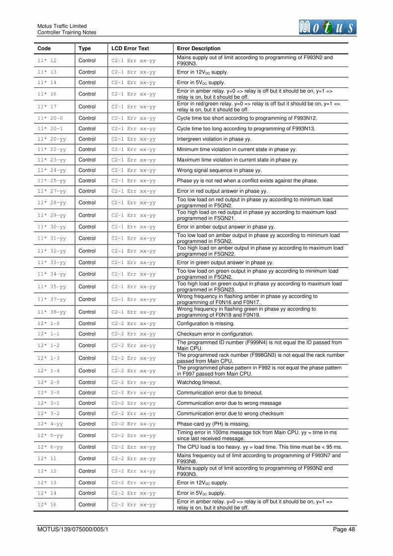
Motus Traffic Limited Controller Training Notes
MOTUS/139/075000/005/1 Page 48
Code Type LCD Error Text Error Description
11* 12 Control C2-1 Err xx-yy Mains supply out of limit according to programming of F993N2 and F993N3.
11* 13 Control C2-1 Err xx-yy Error in 12VDC supply.
11* 14 Control C2-1 Err xx-yy Error in 5VDC supply.
11* 16 Control C2-1 Err xx-yy Error in amber relay. y=0 => relay is off but it should be on, y=1 => relay is on, but it should be off.
11* 17 Control C2-1 Err xx-yy Error in red/green relay. y=0 => relay is off but it should be on, y=1 => relay is on, but it should be off.
11* 20-0 Control C2-1 Err xx-yy Cycle time too short according to programming of F993N12.
11* 20-1 Control C2-1 Err xx-yy Cycle time too long according to programming of F993N13.
11* 20-yy Control C2-1 Err xx-yy Intergreen violation in phase yy.
11* 22-yy Control C2-1 Err xx-yy Minimum time violation in current state in phase yy.
11* 23-yy Control C2-1 Err xx-yy Maximum time violation in current state in phase yy.
11* 24-yy Control C2-1 Err xx-yy Wrong signal sequence in phase yy.
11* 25-yy Control C2-1 Err xx-yy Phase yy is not red when a conflict exists against the phase.
11* 27-yy Control C2-1 Err xx-yy Error in red output answer in phase yy.
11* 28-yy Control C2-1 Err xx-yy Too low load on red output in phase yy according to minimum load programmed in F5GN2.
11* 29-yy Control C2-1 Err xx-yy Too high load on red output in phase yy according to maximum load programmed in F5GN21.
11* 30-yy Control C2-1 Err xx-yy Error in amber output answer in phase yy.
11* 31-yy Control C2-1 Err xx-yy Too low load on amber output in phase yy according to minimum load programmed in F5GN2.
11* 32-yy Control C2-1 Err xx-yy Too high load on amber output in phase yy according to maximum load programmed in F5GN22.
11* 33-yy Control C2-1 Err xx-yy Error in green output answer in phase yy.
11* 34-yy Control C2-1 Err xx-yy Too low load on green output in phase yy according to minimum load programmed in F5GN2.
11* 35-yy Control C2-1 Err xx-yy Too high load on green output in phase yy according to maximum load programmed in F5GN23.
11* 37-yy Control C2-1 Err xx-yy Wrong frequency in flashing amber in phase yy according to programming of F0N16 and F0N17.
11* 38-yy Control C2-1 Err xx-yy Wrong frequency in flashing green in phase yy according to programming of F0N18 and F0N19.
12* 1-0 Control C2-2 Err xx-yy Configuration is missing.
12* 1-1 Control C2-2 Err xx-yy Checksum error in configuration.
12* 1-2 Control C2-2 Err xx-yy The programmed ID number (F999N4) is not equal the ID passed from Main CPU.
12* 1-3 Control C2-2 Err xx-yy The programmed rack number (F998GN3) is not equal the rack number passed from Main CPU.
12* 1-4 Control C2-2 Err xx-yy The programmed phase pattern in F992 is not equal the phase pattern in F997 passed from Main CPU.
12* 2-0 Control C2-2 Err xx-yy Watchdog timeout.
12* 3-0 Control C2-2 Err xx-yy Communication error due to timeout.
12* 3-1 Control C2-2 Err xx-yy Communication error due to wrong message
12* 3-2 Control C2-2 Err xx-yy Communication error due to wrong checksum
12* 4-yy Control C2-2 Err xx-yy Phase-card yy (PH) is missing.
12* 5-yy Control C2-2 Err xx-yy Timing error in 100ms message tick from Main CPU. yy = time in ms since last received message.
12* 6-yy Control C2-2 Err xx-yy The CPU load is too heavy. yy = load time. This time must be < 95 ms.
12* 11 Control C2-2 Err xx-yy Mains frequency out of limit according to programming of F993N7 and F993N8.
12* 12 Control C2-2 Err xx-yy Mains supply out of limit according to programming of F993N2 and F993N3.
12* 13 Control C2-2 Err xx-yy Error in 12VDC supply.
12* 14 Control C2-2 Err xx-yy Error in 5VDC supply.
12* 16 Control C2-2 Err xx-yy Error in amber relay. y=0 => relay is off but it should be on, y=1 => relay is on, but it should be off.

Motus Traffic Limited 2015 Controller Training Notes
Page 49 MOTUS/139/075000/005/1
Code Type LCD Error Text Error Description
12* 17 Control C2-2 Err xx-yy Error in red/green relay. y=0 => relay is off but it should be on, y=1 => relay is on, but it should be off.
12* 20-0 Control C2-2 Err xx-yy Cycle time too short according to programming of F993N12.
12* 20-1 Control C2-2 Err xx-yy Cycle time too long according to programming of F993N13.
12* 20-yy Control C2-2 Err xx-yy Intergreen violation in phase yy.
12* 22-yy Control C2-2 Err xx-yy Minimum time violation in current state in phase yy.
12* 23-yy Control C2-2 Err xx-yy Maximum time violation in current state in phase yy.
12* 24-yy Control C2-2 Err xx-yy Wrong signal sequence in phase yy.
12* 25-yy Control C2-2 Err xx-yy Phase yy is not red when a conflict exists against the phase.
12* 27-yy Control C2-2 Err xx-yy Error in red output answer in phase yy.
12* 28-yy Control C2-2 Err xx-yy Too low load on red output in phase yy according to minimum load programmed in F5GN2.
12* 29-yy Control C2-2 Err xx-yy Too high load on red output in phase yy according to maximum load programmed in F5GN21.
12* 30-yy Control C2-2 Err xx-yy Error in amber output answer in phase yy.
12* 31-yy Control C2-2 Err xx-yy Too low load on amber output in phase yy according to minimum load programmed in F5GN2.
12* 32-yy Control C2-2 Err xx-yy Too high load on amber output in phase yy according to maximum load programmed in F5GN22.
12* 33-yy Control C2-2 Err xx-yy Error in green output answer in phase yy.
12* 34-yy Control C2-2 Err xx-yy Too low load on green output in phase yy according to minimum load programmed in F5GN2.
12* 35-yy Control C2-2 Err xx-yy Too high load on green output in phase yy according to maximum load programmed in F5GN23.
12* 37-yy Control C2-2 Err xx-yy Wrong frequency in flashing amber in phase yy according to programming of F0N16 and F0N17.
12* 38-yy Control C2-2 Err xx-yy Wrong frequency in flashing green in phase yy according to programming of F0N18 and F0N19.
13* Control Cx missing Safety CPU Cx is missing. Replace or insert a new unit.
14* Control Cx 12V supply The 12VDC supply measured by the Safety CPU Cx is faulty. Check the potentials on the power supply.
15* Control Cx Temp to High The temperature measured by Safety CPU Cx is above the threshold programmed in F993N17
16 - - Reserved.
17* Control Cx Mains (xxxV)
The mains supply measured by Safety CPU Cx is outside the limits programmed in F993N2-3 or below the auxiliary level programmed in F993N5. The measured mains is xxx (maximum of xxx is 255)
18* Control Cx-y RG relay
The red/green signal relay belonging to intersection set y in Safety CPU Cx is faulty. Check the cabling to the relay, replace the relay, or replace the Safety CPU.
19* Control Cx-y Amb relay
The amber signal relay belonging to intersection set y in Safety CPU Cx is faulty. Check the cabling to the relay, replace the relay, or replace the Safety CPU.
20* - - Reserved.
21,0* Control Cx Ext. xx Safety CPU Cx reports extended error xx. Reserved for future use.
21,1* Control Cx No config No configuration has been performed for Safety CPU Cx
21,2* Control Cx Config err Configuration error in Safety CPU Cx
21,3* Control Cx Wrong Idno The programmed ID number (F999N4) is not equal the ID read from the backplane.
21,5* Control Cx Safety CPUFLICT
chks
The checksum over the used phases in the conflict matrix in Safety CPU Cx (function F993) is not identical with the checksum obtained from function F997
21,6* Control Cx WD timeout A watchdog timeout fault has occurred in Safety CPU Cx.
21,7* Control Cx Mains freq.
Safety CPU Cx has registered a non-acceptable variation in mains frequency according to the programming of parameters F993N7 and F993N8.
21,8* Control Cx Comm timeout Safety CPU Cx has registered a timeout in the serial communications with the CPU
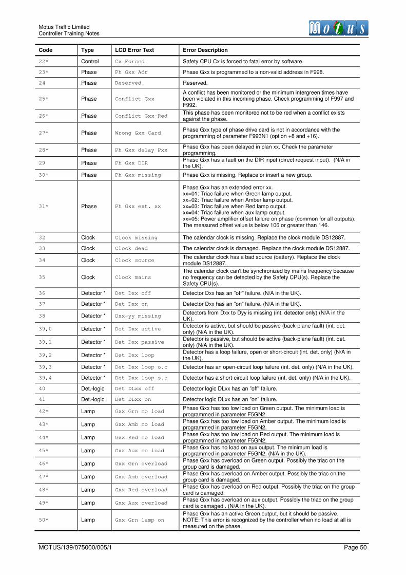
Motus Traffic Limited Controller Training Notes
MOTUS/139/075000/005/1 Page 50
Code Type LCD Error Text Error Description
22* Control Cx Forced Safety CPU Cx is forced to fatal error by software.
23* Phase Ph Gxx Adr Phase Gxx is programmed to a non-valid address in F998.
24 Phase Reserved. Reserved.
25* Phase Conflict Gxx
A conflict has been monitored or the minimum intergreen times have been violated in this incoming phase. Check programming of F997 and F992.
26* Phase Conflict Gxx-Red This phase has been monitored not to be red when a conflict exists against the phase.
27* Phase Wrong Gxx Card Phase Gxx type of phase drive card is not in accordance with the programming of parameter F993N1 (option +8 and +16).
28* Phase Ph Gxx delay Pxx Phase Gxx has been delayed in plan xx. Check the parameter programming.
29 Phase Ph Gxx DIR Phase Gxx has a fault on the DIR input (direct request input). (N/A in the UK).
30* Phase Ph Gxx missing Phase Gxx is missing. Replace or insert a new group.
31* Phase Ph Gxx ext. xx
Phase Gxx has an extended error xx. xx=01: Triac failure when Green lamp output. xx=02: Triac failure when Amber lamp output. xx=03: Triac failure when Red lamp output. xx=04: Triac failure when aux lamp output. xx=05: Power amplifier offset failure on phase (common for all outputs). The measured offset value is below 106 or greater than 146.
32 Clock Clock missing The calendar clock is missing. Replace the clock module DS12887.
33 Clock Clock dead The calendar clock is damaged. Replace the clock module DS12887.
34 Clock Clock source The calendar clock has a bad source (battery). Replace the clock module DS12887.
35 Clock Clock mains
The calendar clock can't be synchronized by mains frequency because no frequency can be detected by the Safety CPU(s). Replace the Safety CPU(s).
36 Detector * Det Dxx off Detector Dxx has an ”off” failure. (N/A in the UK).
37 Detector * Det Dxx on Detector Dxx has an ”on” failure. (N/A in the UK).
38 Detector * Dxx-yy missing Detectors from Dxx to Dyy is missing (int. detector only) (N/A in the UK).
39,0 Detector * Det Dxx active Detector is active, but should be passive (back-plane fault) (int. det. only) (N/A in the UK).
39,1 Detector * Det Dxx passive Detector is passive, but should be active (back-plane fault) (int. det. only) (N/A in the UK).
39,2 Detector * Det Dxx loop Detector has a loop failure, open or short-circuit (int. det. only) (N/A in the UK).
39,3 Detector * Det Dxx loop o.c Detector has an open-circuit loop failure (int. det. only) (N/A in the UK).
39,4 Detector * Det Dxx loop s.c Detector has a short-circuit loop failure (int. det. only) (N/A in the UK).
40 Det.-logic Det DLxx off Detector logic DLxx has an ”off” failure.
41 Det.-logic Det DLxx on Detector logic DLxx has an ”on” failure.
42* Lamp Gxx Grn no load Phase Gxx has too low load on Green output. The minimum load is programmed in parameter F5GN2.
43* Lamp Gxx Amb no load Phase Gxx has too low load on Amber output. The minimum load is programmed in parameter F5GN2.
44* Lamp Gxx Red no load Phase Gxx has too low load on Red output. The minimum load is programmed in parameter F5GN2.
45* Lamp Gxx Aux no load Phase Gxx has no load on aux output. The minimum load is programmed in parameter F5GN2. (N/A in the UK).
46* Lamp Gxx Grn overload Phase Gxx has overload on Green output. Possibly the triac on the group card is damaged.
47* Lamp Gxx Amb overload Phase Gxx has overload on Amber output. Possibly the triac on the group card is damaged.
48* Lamp Gxx Red overload Phase Gxx has overload on Red output. Possibly the triac on the group card is damaged.
49* Lamp Gxx Aux overload Phase Gxx has overload on aux output. Possibly the triac on the group card is damaged . (N/A in the UK).
50* Lamp Gxx Grn lamp on
Phase Gxx has an active Green output, but it should be passive. NOTE: This error is recognized by the controller when no load at all is measured on the phase.

Motus Traffic Limited 2015 Controller Training Notes
Page 51 MOTUS/139/075000/005/1
Code Type LCD Error Text Error Description
51* Lamp Gxx Amb lamp on Phase Gxx has an active Amber output, but it should be passive.
52* Lamp Gxx Red lamp on Phase Gxx has an active Red output, but it should be passive.
53* Lamp Gxx Aux lamp on Phase Gxx has an active Aux output, but it should be passive. (N/A in the UK).
54* Lamp Gxx Grn no fuse Phase Gxx has a damaged Green-output fuse.
55* Lamp Gxx Amb no fuse Phase Gxx has a damaged Amber-output fuse.
56* Lamp Gxx Red no fuse Phase Gxx has a damaged Red-output fuse.
57* Lamp Gxx Aux no fuse Phase Gxx has a damaged aux-output fuse.
58 Lamp Gxx Grn L1 xxxV Phase Gxx has a level 1 error on Green output and mains is measured to xxx voltage.
59 Lamp Gxx Amb L1 xxxV Phase Gxx has a level 1 error on Amber output. See also error code 58.
60 Lamp Gxx Red L1 xxxV Phase Gxx has a level 1 error on Red output. See also error code 58.
61 Lamp Gxx Aux L1 xxxV Phase Gxx has a level 1 error on Aux output. See also error code 58.
62 Lamp Gxx Grn L2 xxxV Phase Gxx has a level 2 error on Green output. See also error code 58.
63 Lamp Gxx Amb L2 xxxV Phase Gxx has a level 2 error on Amber output. See also error code 58.
64* Lamp Gxx Red L2 xxxV Phase Gxx has a level 2 error on Red output. See also error code 58. This can be programmed to be fatal error on a crossing.
65 Lamp Gxx Aux L2 xxxV Phase Gxx has a level 2 error on aux output. See also error code 58.
66 Plan Base cycle tpxx The base cycle counter has not been reset in plan tpxx.
67 Plan No TPm input Input TPm is missing. (Not Used in UK).
68 Plan No.valid tpxxyy A change to the non valid plan tpxx has been tried by plan source yy. Parameter F3PN1 is programmed to 0 in the plan.
69* Plan No valid tps No valid plans exists. Parameter F3PN1 is programmed to 0 in all plans.
70 Plan Reserved. Reserved.
71 Situation No TSm input Input TSm is missing. (Situations not used in UK).
72 Situation Reserved. Reserved. (Situations not used in the UK)
80 Clock No Clock signal A valid DCF radio signal has not been received within 18 hours.
81,0 Comm. Svision No IC Supervision interface error. No communications IC can be found according to the programming of the supervision interface (F30).
81,1 Comm. Svision No modem Supervision interface error. No modem can be found.
81,2 Comm. Svision PIN err Supervision interface error. Wrong PIN code has been entered for the SIM card. This fault can only be cleared by manual resetting of errors.
81,3 Comm. Svision No PIN Supervision interface error. No PIN code has been defined for the SIM card.
81,4 Comm. Svision No hw-hs No hardware handshake signals are available in the supervision interface as required by the programming of F30.
82,0 Comm. XNET No IC Network error. No communications IC can be found according to the programming of the XNET network (F31).
82,1 Comm. XNET No slaves Network error. No slave controllers are responding to the query.
82,2 Comm. XNET No master Network error. No master controller is doing any query.
82,3 Comm. XNET2 No master Network error. No master controller is doing any query on the secondary network interface.
82,4 Comm. XNET No logicAdr Network error. Logical address in parameter F29N4 is not programmed.
83,0 Comm. ComAuxX No IC No communication IC can be found according to the programming of auxiliary interface X.
83,1 Comm. ComAuxX Comm err The communication is faulty in the auxiliary interface X.
83,2 Comm ComAuxX No hw-hs No hardware handshake signals are available in aux. interface X as required by the programming of F32.

Motus Traffic Limited Controller Training Notes
MOTUS/139/075000/005/1 Page 52
Code Type LCD Error Text Error Description
84 Lamp No lampload ref No updating of the lamp-load references (F104) has been performed as required in the programming of error level 1 and 2 in function F5.
91 Various C.Block CBxx yy Instruction yy in control block no. xx is erroneous.
5.1.1 Event Log Annotation Table 5.1.1 is a listing of annotation in event log.
Table 5.1.1 Annotation in The Event Log
Code Text Description
0 Clearing of LOG Clearing of all events in the log.
1 Power-up xxhxxm The controller is powered up and has been without power for xx hours and xx minutes.
2 Power-up xxmxxs Same as code 1, but the time is given in xx minutes and xx seconds.
3 Ix Lamp mains on Lamp mains is switched ON in intersection Ix.
4 Ix Lamp mains off Lamp mains is switched OFF in intersection Ix.
5 Key levelx opened Code level x has been opened.
6 Key closed Code level has been closed.
7 New par checksum A new parameter checksum has been calculated.
8 Ix Manual PB on Manual control is switched on in intersection Ix.
9 Ix Manual PB off Manual control is switched off in intersection Ix.
10 Ix Fixed PB on Fixed control is switched on in intersection Ix.
11 Ix Fixed PB off Fixed control is switched off in intersection Ix.
12 Ix Local PB on Local control is switched on in intersection Ix.
13 Ix Local PB off Local control is switched off in intersection Ix.
14 Reserved.
15 Reserved.
16 Ix All-Red PB on All-Red is switched on in intersection Ix.
17 Ix All-Red PB off All-Red is switched off in intersection Ix.
18 Ix Lamp sv. On Lamp load supervision is active in intersection Ix (default).
19 Ix Lamp sv. Off Lamp load supervision is not active in intersection Ix.
20 Lamp load ref on Lamp load references are in use.
21 Lamp load ref off Lamp load references are not in use.
22 Ix Police key: x State of police key = x in intersection Ix (0 = not in use, 1 = signals off).
23 Ix F109: CFM=OK The conflict-matrix has been approved by function 109 in intersection Ix.
24 PB cmd – Remote-x
The following PB event has been activated remotely from interface x. x=1: Terminal interface. x=2: Supervision interface. x=3: Work station.
25 PB cmd – C.block The following PB event has been activated from the control blocks.
26 Ix Dark PB on Dark control is switched on in intersection Ix.
27 Ix Dark PB off Dark control is switched off in intersection Ix.
28 Route xxx ON (yy) Emergency-route xxx has been activated. yy = number of emergency-logic.
29 Route xxx OFF(yy) Emergency-route xxx has been deactivated. yy = number of emergency-logic.
30 Network +nodeX Node no. X has been added to the network.
31 Network –nodeX Node no. X has been removed from the network.
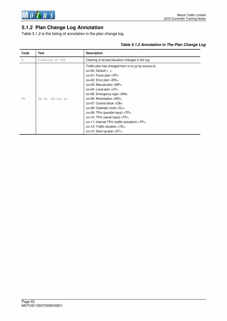
Motus Traffic Limited 2015 Controller Training Notes
Page 53 MOTUS/139/075000/005/1
5.1.2 Plan Change Log Annotation Table 5.1.2 is the listing of annotation in the plan change log.
Table 5.1.2 Annotation in The Plan Change Log
Code Text Description
0 Clearing of LOG Clearing of all plan/situation-changes in the log.
91 Tp ch. Xx->yy zz
Traffic plan has changed from xx to yy by source zz.
zz=00: Default < >.
zz=01: Force plan <FP>.
zz=02: Error plan <ER>.
zz=03: Manual plan <MP>.
zz=04: Local plan <LP>.
zz=05: Emergency logic <EM>.
zz=06: Workstation <WS>.
zz=07: Control block <CB>.
zz=08: Calendar clock <CL>.
zz=09: TPm (parallel input) <TP>.
zz=10: TPm (serial input) <TP>.
zz=11: Internal TPm (traffic actuation) <TP>.
zz=12: Traffic situation <TS>.
zz=13: Start-up plan <ST>.

Motus Traffic Limited Controller Training Notes
MOTUS/139/075000/005/1 Page 54
6 Glossary
Term Description
Aspect Individual light forming part of a traffic signal
Blackout Period of non-illumination, i.e. the traffic signal is dark
Conflict A phase that cannot be green at the same time as another, is said to conflict. For example on a pedestrian crossing, the green man conflicts with green to traffic
Controller Traffic Signal Controller
CPU Central Processing Unit
Correspondence A form of monitoring, if an aspect lights up when it isn’t expected to, then this is a correspondence fault
Drop Cable Cable used to connect the Signal Head to the termination block in the bottom of the signal pol
ELV Extra Low Voltage i.e. <50Vac
FAT Factory Acceptance Test
Force bit Control bit sent by a UTC computer to a TSC
Green Green Traffic Signal means road users can go
Intergreen Time between two conflicting signal phases, one losing green and the other gaining green. Can also be used as a stage term
Leaving Amber Traffic Signal displays Amber aspect on its own for 3s (Standard time)
LV Low Voltage i.e. 230Vac
Minimum green Minimum time that green shall be displayed for, the green time cannot be shorter than this time
Mode Controllers have different modes of operation, e.g. Manual Mode
Phase Collection of traffic signals that are driven by the same output from the controller
Plan A plan is a collection of settings that are loaded into the controller when it is active. In the Motus controller, plans are linked to modes of operation
RAG Standard traffic signal head; Red Amber Green
Red Red Traffic Signal means road users must stop
Reply bit Reply bit is sent from the TSC back to the UTC computer to indicate a state or function of the controller that time
SAT Site Acceptance Test
Solar Cell Sometimes known as PEC (Photo Electric Cell), activates when below 55 lux light level. Used to switch an input to the controller to dim the lights
Stage Collection of phases that can display green at the same time
Starting Amber Traffic Signal displays Red and Amber Aspects at same time for 2s (Standard time)
Start-up Sequence The order in which all the signals connected to the controller display their output when first turned on. For example, blackout to phases in stage that will first run, leaving amber then red to phases conflicting with that stage
Stream Collection of Stages that can run independently of each other controlled by same controller
Switched Sign Un-monitored green aspect phase output switched by special conditioning inside the controller
TR2500 UK Highways Agency Specification for Traffic Signal Controllers
Traffic Signal Sequence
The order in which a traffic signal displays the colours of signal to road users
UTC Urban Traffic Control: A controller mode, where the stage order and duration is determined by inputs received from an external control computer
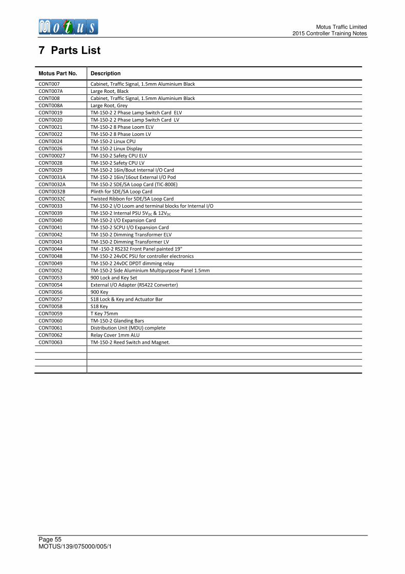
Motus Traffic Limited 2015 Controller Training Notes
Page 55 MOTUS/139/075000/005/1
7 Parts List
Motus Part No. Description
CONT007 Cabinet, Traffic Signal, 1.5mm Aluminium Black
CONT007A Large Root, Black
CONT008 Cabinet, Traffic Signal, 1.5mm Aluminium Black
CONT008A Large Root, Grey
CONT0019 TM-150-2 2 Phase Lamp Switch Card ELV
CONT0020 TM-150-2 2 Phase Lamp Switch Card LV
CONT0021 TM-150-2 8 Phase Loom ELV
CONT0022 TM-150-2 8 Phase Loom LV
CONT0024 TM-150-2 Linux CPU
CONT0026 TM-150-2 Linux Display
CONT00027 TM-150-2 Safety CPU ELV
CONT0028 TM-150-2 Safety CPU LV
CONT0029 TM-150-2 16in/8out Internal I/O Card
CONT0031A TM-150-2 16in/16out External I/O Pod
CONT0032A TM-150-2 SDE/SA Loop Card (TIC-800E)
CONT0032B Plinth for SDE/SA Loop Card
CONT0032C Twisted Ribbon for SDE/SA Loop Card
CONT0033 TM-150-2 I/O Loom and terminal blocks for Internal I/O
CONT0039 TM-150-2 Internal PSU 5VDC & 12VDC
CONT0040 TM-150-2 I/O Expansion Card
CONT0041 TM-150-2 SCPU I/O Expansion Card
CONT0042 TM-150-2 Dimming Transformer ELV
CONT0043 TM-150-2 Dimming Transformer LV
CONT0044 TM -150-2 RS232 Front Panel painted 19"
CONT0048 TM-150-2 24vDC PSU for controller electronics
CONT0049 TM-150-2 24vDC DPDT dimming relay
CONT0052 TM-150-2 Side Aluminium Multipurpose Panel 1.5mm
CONT0053 900 Lock and Key Set
CONT0054 External I/O Adapter (RS422 Converter)
CONT0056 900 Key
CONT0057 S18 Lock & Key and Actuator Bar
CONT0058 S18 Key
CONT0059 T Key 75mm
CONT0060 TM-150-2 Glanding Bars
CONT0061 Distribution Unit (MDU) complete
CONT0062 Relay Cover 1mm ALU
CONT0063 TM-150-2 Reed Switch and Magnet.
Motus Traffic Limited Controller Training Notes
MOTUS/139/075000/005/1 Page 56
END OF DOCUMENT