Titre: Steel slag filter design criteria for phosphorus ...
37
Titre: Title: Steel slag filter design criteria for phosphorus removal from wastewater in decentralized applications Auteurs: Authors: Dominique Claveau-Mallet, Étienne Boutet et Yves Comeau Date: 2018 Type: Article de revue / Journal article Référence: Citation: Claveau-Mallet, D., Boutet, É. & Comeau, Y. (2018). Steel slag filter design criteria for phosphorus removal from wastewater in decentralized applications. Water Research, 143, p. 28-37. doi:10.1016/j.watres.2018.06.032 Document en libre accès dans PolyPublie Open Access document in PolyPublie URL de PolyPublie: PolyPublie URL: https://publications.polymtl.ca/5295/ Version: Version finale avant publication / Accepted version Révisé par les pairs / Refereed Conditions d’utilisation: Terms of Use: CC BY-NC-ND Document publié chez l’éditeur officiel Document issued by the official publisher Titre de la revue: Journal Title: Water Research (vol. 143) Maison d’édition: Publisher: Elsevier URL officiel: Official URL: https://doi.org/10.1016/j.watres.2018.06.032 Mention légale: Legal notice: Ce fichier a été téléchargé à partir de PolyPublie, le dépôt institutionnel de Polytechnique Montréal This file has been downloaded from PolyPublie, the institutional repository of Polytechnique Montréal http://publications.polymtl.ca
Transcript of Titre: Steel slag filter design criteria for phosphorus ...

Titre:
Title:
Steel slag filter design criteria for phosphorus removal from
wastewater in decentralized applications
Auteurs:
Authors: Dominique Claveau-Mallet, Étienne Boutet et Yves Comeau
Date: 2018
Type: Article de revue / Journal article
Référence: Citation:
Claveau-Mallet, D., Boutet, É. & Comeau, Y. (2018). Steel slag filter design
criteria for phosphorus removal from wastewater in decentralized
applications. Water Research, 143, p. 28-37. doi:10.1016/j.watres.2018.06.032
Document en libre accès dans PolyPublie Open Access document in PolyPublie
URL de PolyPublie: PolyPublie URL: https://publications.polymtl.ca/5295/
Version: Version finale avant publication / Accepted version
Révisé par les pairs / Refereed
Conditions d’utilisation:
Terms of Use: CC BY-NC-ND
Document publié chez l’éditeur officiel Document issued by the official publisher
Titre de la revue: Journal Title: Water Research (vol. 143)
Maison d’édition: Publisher: Elsevier
URL officiel: Official URL: https://doi.org/10.1016/j.watres.2018.06.032
Mention légale: Legal notice:
Ce fichier a été téléchargé à partir de PolyPublie, le dépôt institutionnel de Polytechnique Montréal
This file has been downloaded from PolyPublie, the institutional repository of Polytechnique Montréal
http://publications.polymtl.ca

1
Steel slag filter design criteria for
phosphorus removal from wastewater
in decentralized applications By Dominique Claveau-Mallet1, Étienne Boutet2 and Yves Comeau1
1Department of Civil, Geological and Mining Engineering, Polytechnique Montreal, Montreal,
Quebec, Canada, H3C 3A7
2Bionest, 55, 12e Rue, C.P. 10070, Shawinigan, Quebec, Canada, G9T 5K7
* corresponding author: [email protected]
Abstract
The objective of this project was to develop a novel phosphorus removal system using steel slag
filters applicable in decentralized applications and to propose design criteria about maintenance
needs. Slag exhaustion functions were measured on 2-3 mm, 3-5 mm, 5-10 mm and 16-23 mm
slag. Three steel slag columns with particle size of 2-3 mm, 3-5 mm and 5-10 mm were fed with
the effluent of an aerated lagoon during 589 days. A barrel reactor test was fed during 365 days
with the effluent of an attached growth aerated biological reactor. The o-PO4 concentration at
the effluent of the 2-3 mm and 3-5 mm columns and barrel reactor test was between 0.04 and
0.3 mg P/L. Particulate phosphorus, however, was removed by about 50%. The P-Hydroslag
model implemented in PHREEQC was successfully calibrated with data from the column test,
and validated with data from the barrel reactor test. The calibrated model was used to simulate
long-term operation of a slag barrel reactor with two parallel streams of five replaceable steel
slag barrels, with total hydraulic retention time of voids of 15 h. The system longevity was
strongly influenced by the influent alkalinity. The simulated longevity was 7 years with an
influent alkalinity of 50 mg CaCO3/L and 2 years with an influent of 210 mg CaCO3/L. The

2
alkalinity of the steel slag filter influent was influenced by the type of aquifer supplying drinking
water, the presence of nitrification activity and by the CO2 concentration in the enriched air of
the upstream biological process. Simulated scenarios with partial barrel replacement (e. g.
barrels 1 and 2 out of 5 replaced at frequency of 0.5, 1, 1.5, 2, 2.5, 3, 3.5 or 4 years) increased
the system longevity up to 14 years while slightly increasing the number of barrels needed.
Keywords
P-Hydroslag; physicochemical modeling; alkalinity; reactive filter; PHREEQC
Abbreviations
Symbol Description Formula or Units
General abbreviations
EAF Electric arc furnace
HRTV Hydraulic retention time of voids h
o-PO4 Orthophosphates mg P/L
TIC Total inorganic carbon mg C/L
TP Total phosphorus mg P/L
TSS Total suspended solids mg/L
Abbreviations for mineral phases
CAL Calcite CaCO3
HAP Hydroxyapatite Ca5OH(PO4)3
MON Monetite CaHPO4
Constants
aCaCl2 Stochiometric coefficient of CaCl2 in slag [-]

3
aCaO Stochiometric coefficient of CaO in slag [-]
𝐵1 and 𝐵2 Regression coefficients in 𝑘𝑑𝑖𝑠𝑠 exhaustion function
𝐷∗ Dispersivity (transport model) [cm]
𝐷𝑏𝑎𝑟𝑟 Diffusion coefficient in the crystal barrier [m2/s]
𝐷𝑛 Exchange factor between effective and immobile porosity
(transport model) [s-1]
𝑘𝐶𝐴𝐿 CAL precipitation constant [mol CAL/s m2 slag]
𝑘𝐻𝐴𝑃 HAP precipitation constant [mol HAP/s m2 slag]
𝑘𝑀𝑂𝑁 MON precipitation constant [mol MON/s m2 slag]
𝑛𝑒 Effective porosity in the slag filter [-]
𝑃1, 𝑃2, 𝑃3 and 𝑃4 Regression coefficients in 𝑝𝐻𝑠𝑎𝑡 exhaustion function
𝑆 Slag specific surface [m2/m3]
Rates, functions and variables
𝐶𝑎𝑂𝑙𝑇𝑂𝑇 Cumulative leached CaO in a batch test [mol/g]
𝑘𝑑𝑖𝑠𝑠 Slag dissolution constant [mol CaO/m2 slag]
𝑝𝐻𝑠𝑎𝑡 Saturation pH in the slag filter [-]
1 Introduction
Phosphorus removal from wastewater in decentralized applications (influent flowrate below
3600 L/d) is a challenge because low costs and low maintenance associated with small-scale
systems are not compatible with phosphorus-removal technologies used in large scale facilities
(Brunce et al. 2018). Steel slag filters are attractive for domestic wastewater treatment in
decentralized applications because of their high phosphorus removal efficiency, low costs and
potential low maintenance needs (Zuo et al. 2017). Effluent o-PO4 concentration as low as 0.1

4
mg P/L were observed in recent studies in which steel slag filters were fed with synthetic
domestic wastewater (Blanco et al. 2016), real domestic wastewater (Hussain et al. 2015) or
pretreated fish farm effluent (Kõiv et al. 2016). Steel slag filters were also used in lab-scale
studies for the treatment of wastewater with high o-PO4 concentration (90 mg P/L, Park et al.
2017) or low o-PO4 concentration (0.025-0.03 mg P/L, Postila et al. 2017). Yet, steel slag filters
are not commonly used for domestic wastewater treatment in decentralized applications
because of the need for neutralizing the alkaline effluent and handling the media replacement
at a reasonable cost.
The main issue related to steel slag filters is the sudden drop in phosphorus removal efficiency
following slag exhaustion (Park et al. 2017). Slag exhaustion involves slag replacement which
requires longevity prediction and a design tool. Some research teams have attempted to
develop longevity prediction tools based on empirical relationship using the slag CaO content
and its retention capacity (Vohla et al. 2011) or using slag properties, hydraulic retention time
and phosphorus concentration (Penn et al. 2016). Recently, the P-Hydroslag model was
developed for the prediction of steel slag filter longevity (Claveau-Mallet et al. 2017). This
mechanistic model was calibrated with synthetic wastewater and could predict breakthrough
curves of pH, o-PO4, calcium and alkalinity of steel slag filters. A preliminary version of the
model was used for design applications (Claveau-Mallet et al. 2015, Kõiv et al. 2016), but this
model remains to be formally validated.
In past studies, limited attention was given to particulate phosphorus in steel slag filters. The
focus was on o-PO4 removal. The fate of particulate phosphorus from influent suspended solids
or from newly formed calcium-phosphates was not specifically addressed. In full-scale
applications, the fate of both soluble and particulate phosphorus should be understood,

5
because tertiary treatment regulations are based on total phosphorus (Metcalf and Eddy -
AECOM 2014).
The objective of this project was to develop a novel phosphorus removal system using steel slag
filters applicable in decentralized applications and to propose design criteria about maintenance
needs.
2 Materials and Methods
2.1 Slag media
The slag media (electric arc furnace steel slag) was produced by Arcelor Mittal and provided by
Minéraux Harsco (Contrecoeur, Canada). The slag properties are presented in Table 1 and were
determined in a previous study (Claveau-Mallet et al. 2017).
Table 1: Electric arc furnace steel slag properties
Property Units Value
Density* g/mL 3.8
Specific surface* m2/g 0.308
Chemical composition*
% Fe2O3: 33; CaO: 30; SiO2: 16; MgO: 12; Al2O3: 6; others oxides: 3
Grain size - 16-23 mm; 5-10 mm; 3-5 mm; 2-3 mm
*measured on a 5-10 mm sample by Claveau-Mallet et al. (2017)
2.2 Determination of exhaustion functions
The principle behind exhaustion functions is to measure the reactive potential of a slag sample
in successive batch tests. In each batch test, the saturation pH and dissolution kinetic constant
were determined by numerical inversion. Between batch tests, the slag sample was aged with
acid baths using HNO3 0.0625 M, which resulted in decreasing the saturation pH and dissolution

6
kinetic constant. The exhaustion functions were obtained by regression from plots of slag
dissolution parameters (saturation pH and dissolution kinetic constant) against total leached
CaO. The full description of the experimental methods and construction procedure of the
exhaustion functions is provided in Claveau-Mallet et al. (2017).
Three exhaustion functions were measured on three 300-g slag samples with particle size of 2-3
mm, 3-5 mm and 16-23 mm. Slag was sieved in the laboratory. Batch tests were conducted with
700 mL of synthetic wastewater composed of tap water and lab-grade salts (KH2PO4, K2HPO4,
CaCl2.2H2O and NaHCO3). The synthetic wastewater composition was pH 7.7 ± 0.2, o-PO4 9.3 ±
0.2 mg P/L, Ca 46 ± 2 mg/L and total inorganic carbon (TIC) 22.6 ± 0.5 mg/L. The batch test water
was analyzed at the beginning and the end of the test for pH, o-PO4, filtered TIC and filtered
calcium. In the numerical inversion, precipitation constants were fixed at kHAP = 10-11.03 mol s-1 m-
2, kMON = 10-8.67 mol s-1 m-2 and kCAL = 10-9 mol s-1 m-2 (Claveau-Mallet et al. 2017).
2.3 The Grandes-Piles WRRF
Both column tests and the barrel reactor tests were conducted at the Grandes-Piles (Quebec,
Canada) Water Resource Recovery Facility (WRRF). The Grandes-Piles WRRF consists of two
vertical walls aerated lagoons where a KAMAK process (Bionest Wastewater Treatment
Solutions 2018) is installed in the upstream two-third of the first lagoon. The KAMAK system is a
lagoon treatment enhancement technology where three settling and clarification zones are
separated by two aerated fixed media biofilm reactors. The Grandes-Piles WRRF influent
flowrate is 130 m3/d (2013 data). The WRRF effluent data was divided into two periods for the
calculation of mean values (Table 2). The two periods did not have the same alkalinity at the
WRRF effluent because of changes in bicarbonate addition to the lagoons and variations in the
process nitrification efficiency.

7
The column tests were conducted with the WRRF effluent.
Table 2 Composition of the Grandes-Piles WRRF and attached growth aerated reactor effluents
Parameter Units WRRF effluent t = 0 to 100 d
WRRF effluent t = 100 to 589 d
Attached growth reactor effluent
pH - 7.64 7.26 7.67
Alk mg CaCO3/L 192 86 61
TP mg P/L 5.1 5.1 5.1
o-PO4 mg P/L 4.6 3.5 5.0
Dissolved Ca
mg/L 15 15 28
TSS mg/L 17 20 15
CBOD5 mg/L 22 18 15
Effluent used as influent of : column tests barrel reactor test
The barrel reactor test were conducted using a full-scale on-site treatment system for a 3-
bedroom-house which consisted of a septic tank followed by an attached growth aerated
reactor. The Grandes-Piles influent was used to feed the septic tank in batch mode (6 h - 9 h; 11
h - 14 h and 17 h - 20 h). The attached growth aerated reactor was fed by the septic tank. The
main composition of the slag filter tests influent is presented in Table 2 and in Appendix.
2.4 Column tests
The column tests were used for model calibration. Three slag filter columns (length = 79 cm and
diameter = 15.1 cm) were fed with the effluent of the WRRF during 589 d (May 2016 to Dec
2017) in a continuous flow mode (Table 3). The 2-3 mm and 3-5 mm slags were sieved at
Grandes-Piles from a 0-5 mm bulk batch. The porosity was determined at the beginning of the
test from filling and emptying the filters with water. At the time of filling, the column was
allowed to rest 2 hours. The needed water volume to completely fill the column was measured
and this volume was assumed to correspond to the void volume of the filter. The filling-
emptying procedure was repeated until the needed volume was constant (three times, volumes

8
presented in Table 3). The column influent and effluent was sampled once a week and analyzed
for pH, o-PO4, TP, alkalinity and calcium.
Table 3: Column tests set-up
Column Grain size Void volume (L) Porosity HRTV
- mm 1st fill 2nd fill 3rd fill % h
1 2-3 6.9 6.0 6.1 40 16
2 3-5 6.8 6.1 6.1 40 16
3 5-10 6.9 6.3 6.3 40 16
2.5 Barrel reactor test
The barrel reactor test was conducted from February 2017 to February 2018 at the Grandes-
Piles WRRF and was used for model validation. The barrel reactor was a novel wastewater
treatment system composed of an underground concrete reactor containing ten slag barrels
(Boutet et al. 2017). The attached growth reactor effluent was sent to the barrel reactor and
was divided into two parallel five-barrel streams according to the batch fed regime of the
upstream on-site treatment process (Figure 1). Each barrel (h = 1 m and V = 220 L) was bottom
fed with an influent pipe passing down the center of the barrel, and overflowed to the next
downstream barrel. The first two barrels were filled with 5-10 mm slag and the remaining
barrels with 3-5 mm slag. 3-5 mm slag was used to increase the reactor longevity while 5-10 mm
slag was used upstream to limit pressure build up by suspended solids. At the end of the five-
barrel stream, the slag treated effluent overflowed into the concrete reactor inter-barrel space
and was neutralized with CO2-enriched air from the attached growth reactor that was coarse
bubbled into the liquid. The HRTV for all 10 barrels was 15 h. The influent, barrel effluent and
neutralization effluent were sampled periodically and analyzed for pH, alkalinity, TP, o-PO4,
calcium and fecal coliforms.

9
Figure 1: Schematic of the barrel reactor test. Dark grey: 5-10 mm slag; pale grey: 3-5 mm slag
(only one 5-barrel stream shown)
2.6 Description of the P-Hydroslag model
The P-Hydroslag model is a mechanistic model that predicts o-PO4 removal in steel slag filters.
The main features of the model are presented in Table 4. Exhaustion functions coefficients were
determined by a logistic function regression (equation 1). In equation 1, CaOltot is the cumulative
leached CaO from the slag (mol/g) while P1 to P4 are regression coefficients. P2 is the saturation
pH of fresh slag and P1 is the minimum saturation pH reached after exhaustion. P3 is the slope of
the regression function and P4 is the location of the inflexion point. The Gujer matrix of the
model is presented in Claveau-Mallet et al. (2017).
Table 4: Conceptual summary of the P-Hydroslag model (Claveau-Mallet et al., 2017)
Process Description
Slag dissolution
Slag CaO dissolves following a first order equation with a saturation term (saturation pH). Slag stoichiometry is assumed to be 1CaO-0.3CaCl2 following calcium calibration in batch tests. Slag aging is considered with experimentally measured exhaustion functions. Slag CaO leaching is limited by Fick’s law of diffusion through a uniform thin film formed of precipitates.
P mineral precipitation
Precipitation of homogeneous hydroxyapatite, heterogeneous hydroxyapatite, monetite and calcite were considered with transformation of monetite into hydroxyapatite. Hydroxyapatite solubility is affected by particle size. Surface or precipitation reactions involving Fe/Al minerals at near-neutral pH were not considered.

10
Hydraulic flow 1D flow in porous media with the advection-diffusion-reaction model.
𝑝𝐻𝑠𝑎𝑡 = 𝑃2 −𝑃2−𝑃1
(1+𝑒−𝑃3(𝐶𝑎𝑂𝑙𝑇𝑂𝑇−𝑃4)) eq. 1
The specific surface of the slag was set at 2.76 x 10⁶, 1.84 x 10⁶ and 0.75 x 10⁶ m2/m3 for 2-3 mm,
3-5 mm and 5-10 mm slag, respectively. In the calibration work, the model was slightly modified
compared to the previous model (Claveau-Mallet et al. 2017) to improve calibration quality.
First, the slag stoichiometric composition was allowed to change according to slag exhaustion,
instead of being constant. The slag formula was defined according to equation 2:
𝑎𝐶𝑎𝑂𝐶𝑎𝑂 ∙ 2(1 − 𝑎𝐶𝑎𝑂)𝑁𝑎𝑂𝐻 ∙ 𝑎𝐶𝑎𝐶𝑙2𝐶𝑎𝐶𝑙2 eq. 2
where aCaO and aCaCl2 are stoichiometric coefficients. aCaO was always set between 0 and 1. As the
slag stoichiometric coefficients were changing as a function of exhaustion, two-step exhaustion
functions for slag stoichiometric coefficients were defined. Second, HAP heterogeneous
precipitation was removed because HAP homogeneous precipitation yielded sufficiently good
calibration results.
2.7 Numerical simulations
Column and barrel tests were simulated using PHREEQC and its IPHREEQC modules for
interfacing with MATLAB (Charlton and Parkhurst 2011). The influent was simulated using the
REACTION datablock and was put in equilibrium with calcite, monetite and hydroxyapatite using
the EQUILIBRIUM_PHASES datablock. Detailed influent calibration results are provided in
Appendix. The column and barrel tests were simulated using the TRANSPORT double porosity
datablock with 20 numerical cells and a tolerance of 10-5. The hydraulic calibration was assumed
from a previous column test with 5-10 mm slag (Claveau-Mallet et al. 2017). The hydraulic

11
parameters were effective porosity ne = 0.359, dispersivity D* = 5 cm and exchange factor
between effective and immobile porosity Dn = 5 x 10⁻⁶ s-1.
Barrel reactor scenarios were simulated by one five-barrel stream with an HRTV of 15 h. The first
two barrels were filled with 5-10 mm slag and the remaining barrels with 3-5 mm slag. The
replacement of the first barrel or the two first barrels was simulated by resetting to zero the
kinetic reactions in numerical cells associated with replaced barrels. Barrels were replaced at a
frequency of 0.5, 1, 1.5, 2, 2.5, 3, 3.5 or 4 years in accordance with a 6-month frequency
maintenance required by the Quebec (Canada) regulation. Simulations were run for 14 years,
which was arbitrarily defined as the maximum reactor longevity. Different simulations were run
with fixed influent alkalinity between 50 and 210 mg CaCO3/L.
2.7.1 Uncertainty associated with steel slag filter modeling and longevity criterion
Steel slag filter modeling is a challenge due to the high variability in the observed o-PO4
concentration at effluent. Experimental o-PO4-pH-Ca points generally follow the equilibrium
state with hydroxyapatite predicted by the P-Hydroslag model, but there is noise in the
relationship, as shown by Figure 2. In this Figure, experimental points from seven past studies
conducted with EAF slag filters are compared to simulated curves in a realistic range for calcium
(25 mg/L to 200 mg/L) and o-PO4 (10 mg P/L). At pH between 8 and 9, the experimental
variability can be fully explained by the model. At pH between 9 and 12, the experimental
variability is greater than what can be predicted by the model. Such variability at high pH can be
explained by a higher uncertainty in pH measurement above 10 or unstable calcium
concentration in slag filters which could make equilibrium state unstable. A rapid drop in
calcium concentration at effluent was reported in studies presented in Figure 2 and by Park et
al. (2017).
12
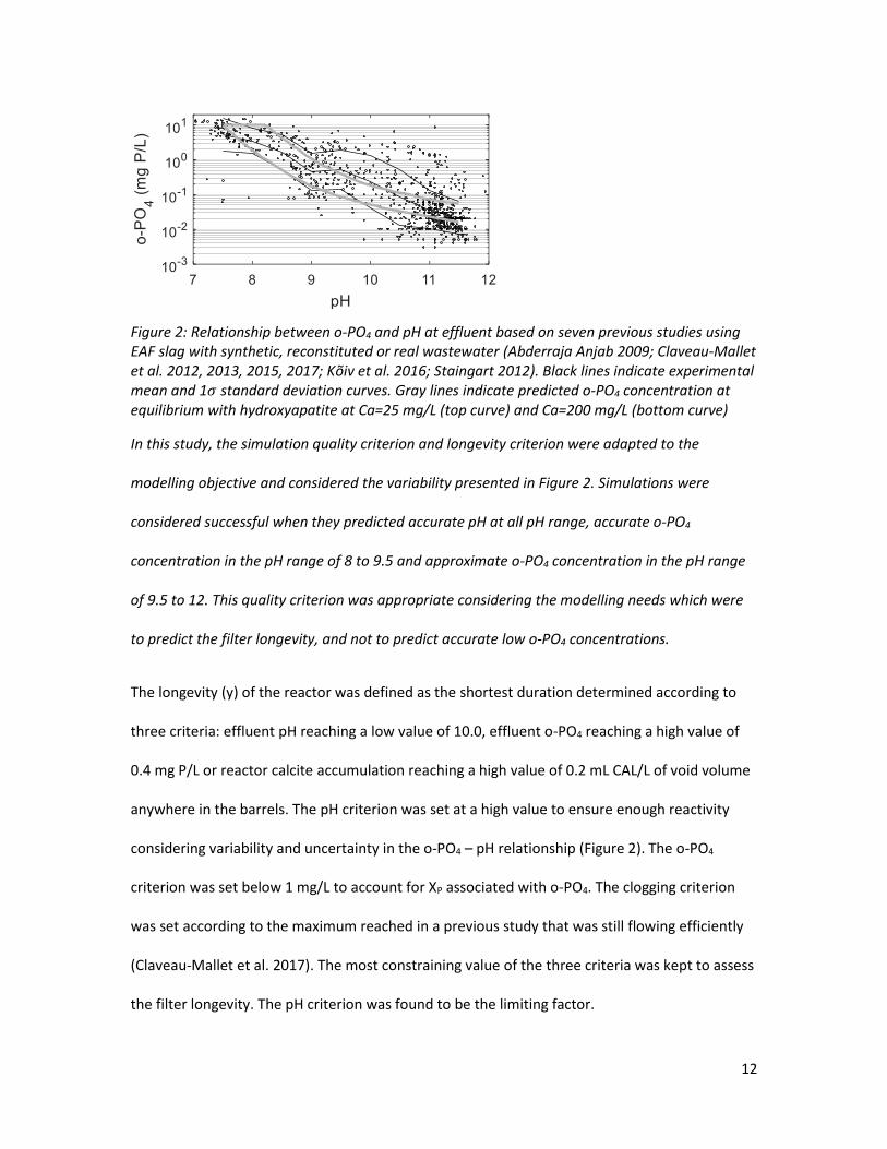
Figure 2: Relationship between o-PO4 and pH at effluent based on seven previous studies using EAF slag with synthetic, reconstituted or real wastewater (Abderraja Anjab 2009; Claveau-Mallet et al. 2012, 2013, 2015, 2017; Kõiv et al. 2016; Staingart 2012). Black lines indicate experimental mean and 1𝜎 standard deviation curves. Gray lines indicate predicted o-PO4 concentration at equilibrium with hydroxyapatite at Ca=25 mg/L (top curve) and Ca=200 mg/L (bottom curve)
In this study, the simulation quality criterion and longevity criterion were adapted to the
modelling objective and considered the variability presented in Figure 2. Simulations were
considered successful when they predicted accurate pH at all pH range, accurate o-PO4
concentration in the pH range of 8 to 9.5 and approximate o-PO4 concentration in the pH range
of 9.5 to 12. This quality criterion was appropriate considering the modelling needs which were
to predict the filter longevity, and not to predict accurate low o-PO4 concentrations.
The longevity (y) of the reactor was defined as the shortest duration determined according to
three criteria: effluent pH reaching a low value of 10.0, effluent o-PO4 reaching a high value of
0.4 mg P/L or reactor calcite accumulation reaching a high value of 0.2 mL CAL/L of void volume
anywhere in the barrels. The pH criterion was set at a high value to ensure enough reactivity
considering variability and uncertainty in the o-PO4 – pH relationship (Figure 2). The o-PO4
criterion was set below 1 mg/L to account for XP associated with o-PO4. The clogging criterion
was set according to the maximum reached in a previous study that was still flowing efficiently
(Claveau-Mallet et al. 2017). The most constraining value of the three criteria was kept to assess
the filter longevity. The pH criterion was found to be the limiting factor.

13
3 Results and Discussion
3.1 Effect of particle size on exhaustion functions
The exhaustion functions of the slag with different particle size are shown in Figure 3. The 5-10
mm data was determined in a previous study in which exhaustion functions were measured with
the same synthetic water, same slag weight and same solution volume (Claveau-Mallet et al.
2017). In Figure 3, experimental data were represented by points while fitted exhaustion
functions were represented by lines. The exhaustion functions parameters are provided in Table
5.
The saturation pH (pHsat) was influenced by particle size (Figure 3A). The initial pHsat of slag with
small particle size of 2-3 mm and 3-5 mm was 11.75 while it was 10.8 for 5-10 mm slag, and 8.75
for 16-23 mm slag. The pHsat exhaustion function of the 16-23 mm indicated that it is not
suitable for steel slag filter applications because its saturation pH was too low. Slag of 2-3 mm
and 3-5 mm had high initial pHsat, which may improve mineral phase seeding, leading to more
stable P retention compared to 5-10 mm slag. The first experimental point was not considered
in the exhaustion function fitting to avoid a calibration artefact caused by the initial washing of
the slag sample. Keeping the first data point in the exhaustion function had the effect to
overestimate pH in the first days of operation and underestimate the longevity in the calibration
work. A refined characterization of the initial slag washing would be possible by the addition of
two or three acid baths with low acid concentration after the initial kinetic test. Exhaustion
functions’ uncertainty could be assessed by testing samples with different acid bath
concentrations.

14
Figure 3: Exhaustion functions of different slag particle size (points = experimental data; lines =
fitted functions used in numerical simulations). Panel A: saturation pH. Panel B: calcium
stoichiometry coefficient. Panel C: Same as panel A, but CaOltot expressed by slag surface
Table 5: Exhaustion functions parameters
Slag particle Regression coefficients
P1 P2 P3 P4
2-3 mm 9.9 11.7 8.50 x 10³ 2.80 x 10⁻⁴
3-5 mm 9.4 11.7 8.50 x 10³ 2.50 x 10⁻⁴
5-10 mm 9.2 12 1.45 x 10⁴ 1.00 x 10⁻⁵
The slag CaO leaching capacity was approximately proportional to the specific surface (Figure
3C). In this figure, the X-axis leached CaO scale was converted from slag mass to slag surface.
The 2-3 mm and 3-5 mm data were superimposed, indicating that the slag reactive CaO
reservoir was proportional to its specific surface within this particle size range. The 5-10 mm
data roughly followed the tendency of 2-3 mm and 3-5 mm data, with the pH being slightly

15
below. As the surface proportionality was validated, it would be possible to estimate exhaustion
functions of slag media with various particle sizes from previous exhaustion functions. In future
measurements of exhaustion functions, the authors recommend to express CaOltot in mol/m2
and to measure the specific surface of every tested slag samples, instead of assuming specific
surface from a single analysis. This should reduce the variability caused by the heterogeneity of
slag.
The slag stoichiometry was not constant following slag leaching (Figure 3B). In the initial model
(Claveau-Mallet et al. 2017), the slag stoichiometry was constant and fixed at 1 CaO 0.3 CaCl2. In
the present work, step functions were defined according to Figure 3B (detailed in Table 6) to
improve calcium calibration. These step functions are a simplification of the successive
dissolution of different complex calcium oxides with decreasing solubility. Such a dissolution
sequence was already observed by Kostura et al. (2005).
Table 6: Slag stoichiometry used in simulations
Particle size
Step 1 Step 2
2-3 mm 0.7 CaO 0.6 NaOH before 3x10⁻⁴ mol/g 1 CaO 0.75 CaCl2 after 3x10⁻⁴ mol/g
3-5 mm 0.8 CaO 0.4 NaOH before 3x10⁻⁴ mol/g 1 CaO 0.85 CaCl2 after 3x10⁻⁴ mol/g
5-10 mm constant at 1.0 CaO 0.3 CaCl2
3.2 Model Calibration
The model calibration results are shown in Figure 4. The calibrated value of the crystal barrier
diffusion coefficient was Dbarr = 2 x 10-13 m2/s. The calibration of pH and calcium was good for
the three particle sizes, showing that the model is suitable for various particle sizes with a single
calibration. The alkalinity calibration was acceptable, with simulated curves slightly below

16
experimental data. The model predicted accurate o-PO4 concentration of 0.8-1 mg P/L when the
pH was between 9 and 10 (column 3).
Figure 4: Calibration of the P-Hydroslag model using three column tests with different particle
size. Exp1 and Sim1: 2-3 mm, Exp2 and Sim2: 3-5 mm, Exp3 and Sim3: 5-10 mm
The o-PO4 experimental data of columns 1 and 2 did not agree with the equilibrium state
predicted by the model. The model predicted an effluent concentration between 0.04 and 0.05
mg P/L, while experimental data ranged between 0.04 and 0.40 mg P/L. The experimental o-PO4
data of columns 1 and 2 were superimposed and they followed three general trends: a slow

17
decrease from 0 to 250 d, followed by a slow rise from 250 to 450 d and finally a slow decrease
from 450 to 600 d. The same trends were roughly observed in the influent o-PO4 concentration,
which suggests that o-PO4 precipitation kinetic rates may be more complex. This limitation is
acceptable considering the simulation quality criterion defined previously.
3.3 Model Validation
The model validation results using the barrel reactor test data are shown in Figure 5. pH was
considered as the most important parameter for model validation, because it reflects the slag
reactivity and thus, the filter longevity. The pH drop had not yet been seen in experimental data,
except for barrel 1. The simulated pH curve of barrel 1 followed experimental data, while it
dropped too early for barrels 2 to 5. The slight underestimation of pH remains appropriate for
design purpose, meaning that the model yields conservative scenarios of longevity prediction.
Note that the low pH observed in all barrels at 200 d was related to an episodic event of high
strength in the influent.
The discrepancy between simulated and experimental pH may be explained, notably, by the slag
sieving protocol. Simulations were realized using exhaustion functions that were measured on a
small slag sample rigorously sieved to the required particle size prior to the test. For the barrels
test, slag was sieved at the slag mill at industrial scale, transported by trucks and filled into the
barrels on site. This slag preparation method resulted in some slag particle breaking during
transportation, as confirmed by small slag grains visible during barrel filling. Thus, the 5-10 mm
barrels contained slag smaller than 5 mm in an unknown proportion, which increased its
reactivity. It resulted in experimental pH of barrels 1 and 2 being higher than what predicted by
the 5-10 mm exhaustion function. The increase of the 5-10 mm barrels reactivity was considered
in the validation by using a slightly increased exhaustion function for 5-10 mm slag (P1=9.35,

18
P2=11.3, P3=1.1 x 10⁴, P4=2 x 10⁻⁴), but the barrel 2 pH was still underestimated (Figure 5). A
similar issue was observed in a previous slag column study in which the measured exhaustion
function was too low to reproduce correctly column pH data (Claveau-Mallet et al. 2017). In this
former study, the column was filled with 5-10 mm that was sieved at the slag mill. The column
tests of the present study were hand-sieved onsite just before filling, which limited particle
breaking. It resulted in pH effluent data that agreed with the 5-10 mm simulation (Figure 4). In
conclusion, the type of slag sieving and transportation affects the slag particle size, thus
affecting its reactivity. The authors recommend to study more in depth this phenomenon in a
quantitative manner, to reduce the simulation uncertainty.
It was not possible to validate the model using o-PO4 data because the filter had not yet reached
its o-PO4 breakthrough. The model underestimated o-PO4 at low o-PO4 concentrations, as
observed in the calibration step. In the first 150 days, the simulated o-PO4 concentration was
0.03 mg P/L in barrels 2 to 5, while experimental data ranged between 0.1 and 0.5 mg P/L. The
simulated and experimental calcium data were in the same order of magnitude. The simulated
alkalinity was slightly lower than the experimental data. Note that the alkalinity peak observed
in experimental data between 150 and 200 d was caused by an influent peak in alkalinity.
Further studies with long-term operation of barrel reactors should be conducted to reinforce
the model robustness.

19
Figure 5: Validation of the P-Hydroslag model using a barrel reactor test. Points: experimental
data, labelled with B as indicated in the legend. Lines: simulated data of barrels 1 to 5, labelled
with S on the right Y axis.
3.4 Particulate phosphorus in steel slag filters
The particulate phosphorus concentration (XP) at the influent and effluent of column tests is
shown in Figure 6. XP was defined as total phosphorus minus o-PO4. All slag columns removed
about 50% of XP at any influent concentration between 0 and 2.5 mg P/L. 2-3 mm slag (column
1) and 3-5 mm slag (column 2) had a similar removal efficiency, while 5-10 mm slag (column 3)
had slightly poorer removal performance due to its coarser size. Similar removal efficiency was

20
observed by Kõiv et al. (2016), who fed 5-10 mm steel slag columns with a fish farm effluent.
Under low-strength conditions (XP = 0.25 mg P/L at influent), these authors observed a mean
value of XP = 0.1 mg P/L in the effluent. The XP removal efficiency was approximately the same
under high-strength conditions (XP = 15 and 5 mg P/L in the influent and effluent, respectively).
Figure 6: Evolution of particulate phosphorus (XP) in the column test (experimental data)
The type and efficiency of the secondary treatment process had an influence on its XP
concentration in the effluent, thus influencing the XP concentration at the effluent of the steel
slag filter. This effect was observed by comparing the column and barrel reactor tests, which had
different upstream secondary treatment processes. The column test influent (from aerated
lagoons) had a mean total suspended solid (TSS) concentration of 19 mg/L associated with XP
between 0.2 and 2 mg P/L (Figure 6). The barrel reactor test influent (from attached growth
aerated reactor) had a TSS concentration of 15 mg/L with an XP concentration of 0.4 mg P/L,
which is lower than the concentrations observed coming out of the aerated lagoons.
Consequently, the XP concentration in the barrel reactor test effluent was very low (mean of
0.06 mg P/L). The mean o-PO4/TP ratio observed in the effluent of the barrel reactor test was
0.93. These results indicate that, as expected, there is a relationship between TSS and XP in the
upstream process that must be considered in the design of steel slag filters. An efficient

21
secondary treatment is needed to ensure efficient P removal in the steel slag filters, because of
a limited XP filtration efficiency; and limit pressure build up in the filter. In Quebec (Canada)
regulations, such efficient secondary treatment is called advanced secondary treatment, which
involves a requirement of TSS = 15 mg/L in the effluent (MDDELCC 2017). For design purposes, it
is recommended to consider an effluent o-PO4/TP ratio of 0.9. Consequently, the TP target of 1
mg P/L corresponds to a o-PO4 longevity target of 0.9 mg P/L in simulations.
Removal mechanisms of XP in steel slag filters are chemisorption and filtration. Chemisorption
means that newly formed calcium phosphate precipitates are incorporated in a fixed crystal
matrix by crystal growth or sorption. The hypothesis that newly formed calcium phosphate
precipitates are stable and not leached is reasonable considering the low turbulence in steel slag
filters and high organization of crystals (Claveau-Mallet et al. 2012). Filtration is the main
mechanism that affects the removal of influent XP. Results of this study indicated a roughly
constant removal efficiency independently of influent concentration, which is in agreement with
the first-order kinetic of filtration accepted in the literature (Tufenkji and Elimelech 2004). The
small influence of slag particle size on filtration efficiency, however, does not agree with
common filtration theory. This result may be attributed to the large particle size of the slag
filters, compared to drinking filtration processes in which particle size is typically below 1 mm.
Filtration models (Tufenkji and Elimelech 2004) may not be directly applicable to gravel-sized
filters. The authors recommend to study the fractionation of XP in steel slag filters in order to
validate the role of filtration and chemisorption. Organic and inorganic XP as well as colloidal
phosphorus may have different fates in steel slag filters.
22
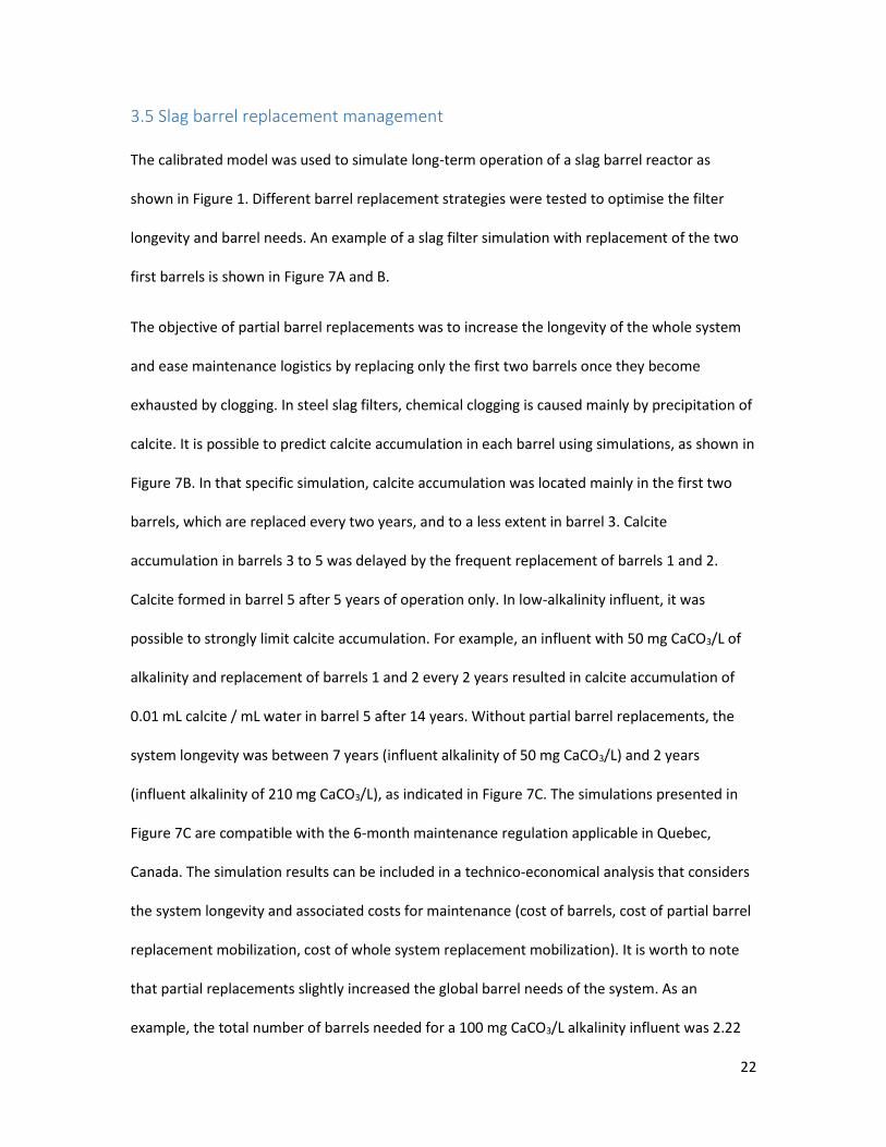
3.5 Slag barrel replacement management
The calibrated model was used to simulate long-term operation of a slag barrel reactor as
shown in Figure 1. Different barrel replacement strategies were tested to optimise the filter
longevity and barrel needs. An example of a slag filter simulation with replacement of the two
first barrels is shown in Figure 7A and B.
The objective of partial barrel replacements was to increase the longevity of the whole system
and ease maintenance logistics by replacing only the first two barrels once they become
exhausted by clogging. In steel slag filters, chemical clogging is caused mainly by precipitation of
calcite. It is possible to predict calcite accumulation in each barrel using simulations, as shown in
Figure 7B. In that specific simulation, calcite accumulation was located mainly in the first two
barrels, which are replaced every two years, and to a less extent in barrel 3. Calcite
accumulation in barrels 3 to 5 was delayed by the frequent replacement of barrels 1 and 2.
Calcite formed in barrel 5 after 5 years of operation only. In low-alkalinity influent, it was
possible to strongly limit calcite accumulation. For example, an influent with 50 mg CaCO3/L of
alkalinity and replacement of barrels 1 and 2 every 2 years resulted in calcite accumulation of
0.01 mL calcite / mL water in barrel 5 after 14 years. Without partial barrel replacements, the
system longevity was between 7 years (influent alkalinity of 50 mg CaCO3/L) and 2 years
(influent alkalinity of 210 mg CaCO3/L), as indicated in Figure 7C. The simulations presented in
Figure 7C are compatible with the 6-month maintenance regulation applicable in Quebec,
Canada. The simulation results can be included in a technico-economical analysis that considers
the system longevity and associated costs for maintenance (cost of barrels, cost of partial barrel
replacement mobilization, cost of whole system replacement mobilization). It is worth to note
that partial replacements slightly increased the global barrel needs of the system. As an
example, the total number of barrels needed for a 100 mg CaCO3/L alkalinity influent was 2.22

23
barrels/year without partial replacements, and 2.54 barrels/year if the first two barrels were
replaced every three years.
Figure 7: Optimization of slag filter replacement using modelling. Panels A, B and C: 14-year
simulation of a steel slag barrel reactor with influent alkalinity = 100 mg CaCO3/L and
replacement of barrels 1 and 2 every 2 years. Panel A: pH at effluent of barrels 1 to 5 (longevity
criterion at pH = 10 is indicated with a horizontal line). Panel B: o-PO4 at effluent of barrels 1 to 5
(longevity criterion at o-PO4 = 0.4 mg P/L is indicated with a horizontal line). Panel C: Calcite
accumulation in barrels 1 to 5. Panel D: Effect of maintenance frequency and influent alkalinity

24
on the slag filter reactor longevity. Replacement frequency of barrels 1 and 2 are indicated in the
legend (years)
The longevity criterion for calcite accumulation was defined because head loss buildup in the
slag filters must be limited to avoid overflow in the upstream process. Two types of clogging
occur in steel slag filters: chemical (calcite and calcium phosphate accumulation, cementation)
and physical (accumulation of suspended solids from the influent). The P-Hydroslag model used
in this project could predict chemical clogging with a quantitative evaluation of calcite
accumulation, but it could not associate it to a pressure build-up. Physical clogging was not
considered in this model. The next step for model development would be to predict head loss
evolution in the filter considering both chemical and physical clogging. Long-term hydraulic
characteristics of the barrel reactor should be evaluated with tracer tests conducted several
times during the filter lifetime (ex. reduction in void volume, development of short-circuiting).
Other full-scale applications of steel slag filters in horizontal flow beds have shown an evolution
of tracer test response over 29 weeks of operation (Barca et al. 2018), which show that initial
hydraulic properties cannot be assumed for the whole lifecycle of the filter.
Simulations with replacement of the first barrel only indicated that this option was not
satisfactory due to excessive calcite precipitation in the second barrel. This behavior is related to
slag dissolution kinetic. In the first barrel, there is enough reaction time to increase the influent
pH, but not enough to reach a pH that favors calcite precipitation. As a result, for a fixed influent
composition, changing the first two barrels every two years resulted in improved longevity
compared to replacement of the first barrel every year.

25
In future research, the barrel reactor geometry will be optimized to limit long term pressure
build-up. Factors such as water distribution in the barrels, slag particle size sequence and
backwash maintenance will be considered.
3.6 Fate of alkalinity in decentralized wastewater treatment
Alkalinity is a major factor that influences the steel slag filter longevity because of chemical
clogging, as shown in Figure 7C. It is therefore important to understand the origin and fate of
alkalinity in decentralized wastewater treatment. Assuming that the steel slag filter is a tertiary
treatment process, it is useful to study the fate of alkalinity in all steps prior to tertiary
treatment: drinking water source, primary treatment and secondary treatment.
In many decentralized applications, the source of drinking water is groundwater from individual
wells. In Quebec (Canada), 20% of the population has groundwater as water supply (MDDELCC
2018). The alkalinity of natural groundwater is related to the type of aquifer. A systematic study
of groundwater quality in the Abitibi region (Quebec, Canada) showed that sediment-based
aquifers have lower alkalinity than fractured-rock aquifers (Cloutier et al. 2013). These authors
reported 125 mg/L of HCO3 in granular aquifers and 200-260 mg/L of HCO3 in rock aquifers. They
also observed higher mineralization in captive aquifers compared to free surface aquifers. Lower
alkalinity may be observed in wells located in alluvial sediments close to lakes or rivers (Bourg
and Bertin 1993).
In secondary treatment, an important process that affects alkalinity is nitrification. Nitrification
is commonly seen as a process that has stoichiometric needs in alkalinity (Metcalf and Eddy -
AECOM 2014). For steel slag filter design, one needs to describe nitrification in a more rigorous
way. Complete nitrification transforms ammonium into nitrate following equation 3, reducing
pH due to H+ production. The pH reduction causes a shift of the carbonate equilibrium to the

26
CO2 size, which lead to CO2 stripping if good mixing conditions are present. Therefore,
nitrification reduces alkalinity by both pH reduction and CO2 stripping.
𝑁𝐻4+ + 2𝑂2 → 𝑁𝑂3
− + 2𝐻+ +𝐻2𝑂 eq. 3
In steel slag filter applications, it is useful to reduce the inorganic carbon concentration of the
influent by CO2 stripping to reduce the filter clogging by CaCO3. In the proposed process
configuration, nitrification is achieved in a confined biological process with an air reservoir with
CO2-enriched air which is used for neutralization of the steel slag filter effluent (Bove et al.
2018). As CO2 stripping follows Henry’s law, the inorganic carbon concentration reduction
induced by nitrification is influenced by the CO2 enriched-air concentration. A CO2 enriched-air
concentration of 1000 to 5000 ppm is expected in a confined biological process with steel slag
filter neutralization (Bove et al. 2018). The effect of nitrification on stripped CO2 under different
conditions is shown in Figure 8. CO2 stripping was favored at low CO2 concentration in the
enriched air. CO2 stripping was maximized at an influent alkalinity of 60-80 mg CaCO3/L.

27
Figure 8: Influence of nitrification on TIC removal in the biological process by CO2 stripping. CO2
concentration in the biological process confined air is indicated next to lines (ppm)
The best way to increase the steel slag filter longevity is to reduce its influent carboneous
alkalinity. The implementation of a secondary treatment with nitrification prior of the steel slag
would reduce the alkalinity. In cold climates, nitrification may not be active. The chemical
dosage of NaHCO3 in the secondary treatment should be avoided. If it is needed for nitrification,
it should be strictly designed to avoid excess NaHCO3. In common small decentralized
applications (influent flowrate below 3240 L/d), however, no NaHCO3 is added. The dosage of
iron coagulant and settling prior to the steel slag filter may promote alkalinity reduction by co-
precipitation of calcite (Metcalf and Eddy - AECOM 2014). This option is possible in WRRFs, but
is not common in small decentralized applications. CO2 enrichment in the secondary treatment
head air must be limited to ease CO2 stripping in the nitrification stage. The use of the enriched
air for neutralization is a useful way to reduce its CO2 concentration. Another approach would
be to ventilate the reactor headspace. Finally, steel slag filter designers may recommend this
process mainly for low alkalinity drinking water sources. This recommendation may be
contradictory with water quality requirements, as groundwater from confined aquifers is safer
than free-surface groundwater regarding microbial contamination.

28
4 Conclusion
The objective of this project was to develop a novel phosphorus removal system using steel slag
filters applicable in decentralized applications and propose design criteria about maintenance
needs. The novel system was made of two parallel streams of five replaceable steel slag barrels
followed by neutralization with CO2-enriched air in the inter-barrel space.
Exhaustion functions were measured on four slag particle sizes. The initial saturation pH was
11.75 for 2-3 mm and 3-5 mm slag while it was 10.8 for 5-10 mm slag, and 8.75 for 16-23 mm
slag. Different saturation pH suggested that the mineralogical composition at the slag surface is
influenced by particle size. The slag CaO leaching capacity was approximately proportional to
the specific surface, which means that it would be possible to estimate exhaustion functions of
slag media with various particle sizes from previous exhaustion functions. In future
measurements of exhaustion functions, the authors recommend to express the slag CaO
leaching by slag surface instead of slag mass.
The P-Hydroslag model was calibrated using three steel slag filters column tests with particle
size of 2-3 mm, 3-5 mm and 5-10 mm and fed with the effluent of an aerated lagoon. The
calibration of pH and calcium was good for the three particle sizes. The addition of step
functions in the slag stoichiometry improved the calcium calibration. The o-PO4 calibration at
the beginning of the filter operation underestimated experimental data, but was accurate to
predict the pH-drop region, which was acceptable considering the modelling objective of
longevity prediction.
The calibrated model was validated using a dataset from a full-scale 5-barrel reactor fed with
the effluent of an attached growth aerated biological reactor. The simulated pH slightly
underestimated experimental data. This slight underestimation of pH remains appropriate for

29
design purpose, meaning that the model yields conservative scenarios of longevity prediction.
Thus, the P-Hydroslag model was shown to be effective for reactor design for real wastewater
conditions. The slag transportation and filling protocol resulted in particle breakage, which
increased the barrel reactivity.
The three steel slag filter columns removed roughly 50% of particulate phosphorus. The type
and efficiency of the upstream secondary treatment process had an influence on its particulate
phosphorus concentration at effluent, thus influencing the particulate phosphorus
concentration at the effluent of the steel slag filter. Upstream processes with efficient TSS
removal (lower than 15 mg/L) are recommended to ensure low total phosphorus at the effluent
of the steel slag filter.
The calibrated model was used to simulate a full-scale long-term operation of a slag barrel
reactor with two parallel streams of five replaceable steel slag barrels, with total hydraulic
retention time of voids of 15 h. Three longevity criteria were defined: reaching an effluent pH of
10.0, reaching an effluent o-PO4 concentration of 0.4 mg P/L and reaching a clogging value of 0.2
mL calcite /mL of water in any barrel. The system longevity was influenced by the influent
alkalinity. It was estimated to be 7 years with an influent of 50 mg CaCO3/L and 2 years with
influent of 210 mg CaCO3/L. In typical decentralized applications with groundwater drinking
water source, the influent alkalinity is influenced by the type of aquifer and presence of
nitrification in the upstream biological process. Scenarios with partial barrel replacement
increased the system longevity of up to 14 years while slightly increasing the number of barrels
needed. The next step for model development would be to predict head loss evolution in the
filter considering both chemical and physical clogging.
30
5 Acknowledgements
This work was funded by the Natural Sciences and Engineering Research Council of Canada
(grant 476673-14), the MITACS Accelerate program (grant IT09967), Bionest, ArcelorMittal,
Harsco Minerals, AgroÉnergie, GHD consulting, the RAQ (Ressources aquatiques Québec) and
NORDIKEau. The authors thank Denis Bouchard, Jérôme Leroy and Manon Leduc from
Polytechnique Montreal for analytical determinations. The authors also thank Serge Baillargeon,
Marc Boissonnault, Wiliam Narbey, Philie Dallaire, Félix Lida and Céline Khuu from Bionest.
6 References
Abderraja Anjab, Z. (2009). Development of a steel slag bed for phosphorus removal from
fishfarm wastewater (In French). M.A.Sc. thesis, Polytechnique Montreal, Canada.
Barca, C., N. Roche, S. Troesch, Y. Andrès and F. Chazarenc. 2018. Modelling hydrodynamics of
horizontal flow steel slag filters designed to upgrade phosphorus removal in small
wastewater treatment plants. Journal of Environmental Management 206, 349-356.
Bionest Wastewater Treatment Solutions. 2018. Our products - Aerated lagoons KAMAK.
Retrieved from http://www.bionest-tech.com/QC-en/product/20-406/.html. Accessed on
January 24th 2018.
Blanco, I., P. Molle, L. Sáenz de Miera and G. Ansola. 2016. Basic Oxygen Furnace steel slag
aggregates for phosphorus treatment. Evaluation of its potential use as a substrate in
constructed wetlands. Water Research 89, 355-365.
Bourg, A. C. and C. Bertin. 1993. Biogeochemical Processes during the Infiltration of River Water
Into an Alluvial Aquifer. Environmental Science and Technology 27, 661-666.

31
Boutet, É., S. Baillargeon, F. Allaire, F. Lida, D. Claveau-Mallet and Y. Comeau. 2017. Apparatus
and method for wastewater treatment, US Provisional Patent Application No. 62/450,210,
filed January 25, 2017.
Bove, P., D. Claveau-Mallet, É. Boutet, F. Lida and Y. Comeau. 2018. Design and modelling of a
steel slag filter effluent neutralization process with passive CO2-enriched air. Water Research
129, 11-19.
Bunce, J. T., E. Ndam, I. D. Ofiteru, A. Moore and D. W. Graham. 2018. A Review of Phosphorus
Removal Technologies and Their Applicability to Small-Scale Domestic Wastewater
Treatment Systems. Frontiers in Environmental Science 6(8), 1-15.
Charlton, S. R. and D. L. Parkhurst. 2011. Modules based on the geochemical model PHREEQC
for use in scripting and programming languages. Computers & Geosciences 37(10), 1653-
1663.
Claveau-Mallet, D., B. Courcelles, P. Pasquier and Y. Comeau. 2017. Numerical Simulations with
the P-Hydroslag Model for Prediction of Phosphorus Removal by Steel Slag Filters. Water
Research 126, 421-432.
Claveau-Mallet, D., F. Lida and Y. Comeau. 2015. Improving phosphorus removal of conventional
septic tanks by a recirculating steel slag filter. Water Quality Research Journal of Canada
50(3), 211-218.
Claveau-Mallet, D., S. Wallace and Y. Comeau. 2012. Model of phosphorus precipitation and
crystal formation in electric arc furnace steel slag filters. Environmental Science and
Technology 46(3), 1465-1470.
Claveau-Mallet, D., S. Wallace and Y. Comeau. 2013. Removal of phosphorus, fluoride and
metals from a gypsum mining leachate using steel slag filters. Water Research 47(4), 1512-
1520.

32
Cloutier, V., D. Blanchette, P.-L. Dallaire, S. Nadeau, E. Rosa and M. Roy. 2013. Project of
knowledge acquisition on groundwater in Abitibi-Témiscamingue (In French). Report
presented to the Ministère du développement durable, de l’environnement, de la faune et des
parcs, program of knowledge acquisition on Quebec groundwater. Quebec University in
Abitibi-Témiscamingue, Report number P001. Retrieved from
http://www.mddelcc.gouv.qc.ca/_PACES/rapports-projets/Abitibi/ABI-scientif-UQAT-
201309.pdf.
Hussain, S. I., D. W. Blowes, C. J. Ptacek, J. H. Jamieson-Hanes, B. Wootton, G. Balch and J.
Higgins. 2015. Mechanisms of phosphorus removal in a pilot-scale constructed wetland/BOF
slag wastewater treatment system. Environmental Engineering Science 32(4), 340-352.
Kõiv, M., K. Mahadeo, S. Brient, D. Claveau-Mallet and Y. Comeau. 2016. Treatment of fish farm
sludge supernatant by aerated filter beds and steel slag filters - effect of organic loading rate.
Ecological Engineering 94, 190-199.
Kostura, B., H. Kulveitová and J. Leško. 2005. Blast furnace slags as sorbents of phosphate from
water solutions. Water Research 39(9), 1795-1802.
MDDELCC. 2018. Groundwater (In French). Ministère du Développement durable, de
l’Environnement et de la Lutte contre les changements climatiques, Government of Quebec.
Retrieved from http://www.mddelcc.gouv.qc.ca/eau/souterraines/index.htm#puits,
Accessed on March 27th 2018.
MDDELCC. 2017. Technical Guide – Wastewater Treatment of Remote Dwellings (In French).
Ministère du Développement durable, de l’Environnement et de la Lutte contre les
changements climatiques, Government of Quebec. Retrieved from
http://www.mddelcc.gouv.qc.ca/eau/eaux-
usees/residences_isolees/guide_interpretation/index.htm

33
Metcalf & Eddy - AECOM, G. Tchobanoglous, H. D. Stensel, R. Tsuchihashi and F. Burton. 2014.
Wastewater engineering: treatment and resource recovery. McGraw-Hill, New York.
Park, T., V. Ampunan, S. Maeng and E. Chung. 2017. Application of steel slag coated with sodium
hydroxide to enhance precipitation-coagulation for phosphorus removal. Chemosphere 167,
91-97.
Penn, C., J. Bowen, J. McGrath, R. Nairn, G. Fox, G. Brown, S. Wilson and C. Gill. 2016. Evaluation
of a universal flow-through model for predicting and designing phosphorus removal
structures. Chemosphere 151, 345-355.
Postila, H., S. M. Karjalainen and B. Kløve. 2017. Can limestone, steel slag or man-made sorption
materials be used to enhance phosphate-phosphorus retention in treatment wetland for
peat extraction runoff with low phosphorus concentration? Ecological Engineering 98, 403-
409.
Staingart, A. (2012). Phosphorus removal fromp septic tank effluents by coarse steel slag (In
French). M.Eng. thesis, Polytechnique Montreal, Canada.
Stumm, W. and J. J. Morgan. 1996. Aquatic Chemistry: Chemical Equilibria and Rates in Natural
Waters. 3rd edition, John Wiley & Sons, New York.
Tufenkji, N. and M. Elimelech. 2004. Correlation equation for predicting single-collector
efficiency in physicochemical filtration in saturated porous media. Environmental Science and
Technology 38, 529-536.
Vohla, C., M. Kõiv, H. J. Bavor, F. Chazarenc and Ü. Mander. 2011. Filter materials for
phosphorus removal from wastewater in treatment wetlands-A review. Ecological
Engineering 37(1), 70-89.

34
Zuo, M., G. Renman, J. P. Gustafsson and W. Klysubun. 2017. Dual slag filters for enhanced
phosphorus removal from domestic waste water: performance and mechanisms.
Environmental Science and Pollution Research, 1-10.

35
6 Appendix
Figure 9: Effluent composition monitoring at the the Grandes-Piles WRRF (experimental data)
and influent calibration of the column test simulation

36
Figure 10: Influent composition monitoring of the barrel reactor test (experimental data) and influent calibration of the barrel test simulation