
Tinh Toan Expansion Tank + Copper Pipe Thick Insulation
70
Water Side Systems MEBS6006 Environmental Services I http://www.hku.hk/bse/MEBS6006 1 Dr. Benjamin P.L. Ho ([email protected]) Part-time Lecturer Department of Mechanical Engineering The University of Hong Kong
-
Upload
trando2310 -
Category
Documents
-
view
49 -
download
2
description
good documents
Transcript of Tinh Toan Expansion Tank + Copper Pipe Thick Insulation

Water Side Systems
MEBS6006 Environmental Services Ihttp://www.hku.hk/bse/MEBS6006
1
Dr. Benjamin P.L. Ho ([email protected])Part-time Lecturer
Department of Mechanical EngineeringThe University of Hong Kong

2
Content
Types of Water SystemsHot & Chilled Water System ArrangementsComponents of Water Systems

3
Types of Water Systems
Hydronic systemsWater systems that convey heat to or from a conditioned space or process with hot or chilled water are frequently called hydronic systems. The water flows through piping that connects a boiler, water heater, or chiller to suitable terminal heat transfer units located at the space or process.
Classification of Water systems based onOperating temperature, Flow generation, Pressurization, Piping arrangement,Pumping arrangement.

4
Types of Water SystemsHot Water SystemsLow-temperature hot water (LTHW) system.
This hydronic heating system operates within the pressure and temperature limits of the ASME Boiler and Pressure Vessel Code for low-pressure boilers. The maximum allowable temperature limitation of 120°C. Steam-to-water or water-to-water heat exchangers are also used for heating low-temperature water.
Medium-temperature hot water (MTHW) system. This hydronic heating system operates at temperatures between 120 and 175°C. The usual design supply temperature is approximately 120 to 160°C.
High-temperature hot water (HTHW) system. This hydronic heating system operates at temperatures over 175°C The maximum design supply water temperature is usually about 200°C.

5
Types of Water Systems
Chilled Water System
Water is first cooled in the water chiller—the evaporator of a reciprocating, screw, or centrifugal refrigeration system located in a centralized plant—to a temperature of 5.6 to 8.3°C .
It is then pumped to the water cooling coils in AHUs and terminals in which air is cooled and dehumidified.
After flowing through the coils, the chilled water increases in temperature up to 12 °C to 14°C and then returns to the chiller.

6
Dual-Temperature Water System
Chilled water or hot water is supplied to the coils in AHUs and terminals and is returned to the water chiller or boiler mainly through :
Separate supply and return main and branch pipes (4 pipe system)Common supply and return mains, branch pipe, and coil for hot and chilled water supply and return (2 pipe system)
Operate within the pressure and temperature limits of LTHW systems, with usual winter design supply water temperatures of about 38 to 65°C and summer supply water temperatures of 4 to 7°C.
The changeover from chilled water to hot water and vice versa in a building or a system depends mainly on the space requirements and the temperature of outdoor air.
Types of Water Systems

7
Condenser Water System
The latent heat of condensation of the refrigerant in the chiller plant is removed in the condenser by the condenser water.
This condenser water is either seawater or fresh water from the Water Authority.
Types of Water Systems

8Direct Return System Reverse Return System
Chilled/ Hot water system: Direct Return/ Reverse Return
Compare path resistance of these two systems
Hot and Chilled Water Systems
9
Hot and Chilled Water Systems
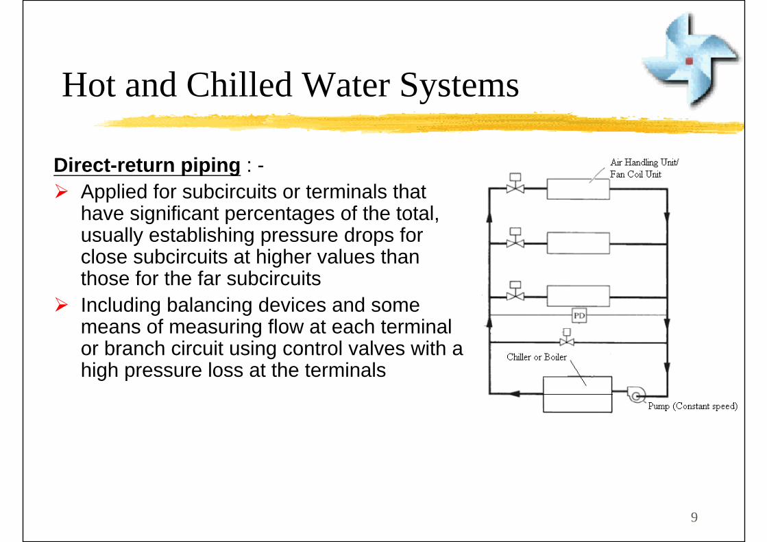
Direct-return piping : -Applied for subcircuits or terminals that have significant percentages of the total, usually establishing pressure drops for close subcircuits at higher values than those for the far subcircuitsIncluding balancing devices and some means of measuring flow at each terminal or branch circuit using control valves with a high pressure loss at the terminals

10
Hot and Chilled Water Systems
Loads must all require cooling or heating coincidentally; that is, if cooling is required for some loads and heating for other loads at a given time, this type of system should not be used.
The changeover procedure should be designed such that the chiller evaporator is not exposed to damaging high water temperatures and the boiler is not subjected to damaging low water temperatures.
If rapid load swings are anticipated, a two-pipe system should not be selected, although it is the least costly of the three options.
Two-Pipe Systems
11
Hot and Chilled Water Systems
Four-Pipe Common Load Systems
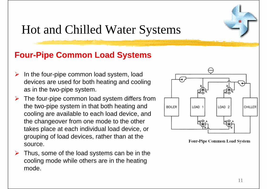
In the four-pipe common load system, load devices are used for both heating and cooling as in the two-pipe system. The four-pipe common load system differs from the two-pipe system in that both heating and cooling are available to each load device, and the changeover from one mode to the other takes place at each individual load device, or grouping of load devices, rather than at the source. Thus, some of the load systems can be in the cooling mode while others are in the heating mode.

12
Hot and Chilled Water Systems
Potential problem is the mixing of hot and chilled water. Limited to those applications in which there are no independent load circuits (i.e., radiant ceiling panels or induction unit coils).

13
Hot and Chilled Water Systems
The four-pipe independent load system is preferred for those hydronic applications in which some of the loads are in the heating mode while others are in the cooling mode. Control is simpler and more reliable than for the common load systems and is less costly to install. The flow through the individual loads can be modulated, providing both the control capability for variable capacity and the opportunity for variable flow in either or both circuits.
Four-Pipe Independent Load Systems

14
Hot and Chilled Water Systems

15
Hot and Chilled Water Systems

16
Variable Chilled Water System (Also known as Decoupler System)
Production loop
There would be more than ONE chiller
Each chiller with one production pump at constant speed
Distribution pump running at variable speed
Bypass line with flow meter to measure the flow
Surplus flow in bypass line leads to stopping of one chiller and production chilled water pump
Deficit in flow in bypass line leads to starting of chiller and production chilled water pump
Distribution loop
2-ways valve close as load reduced & flow resistance increase
Distribution loop flow changed by change in pumps in operation or speed of distribution pump
Hot and Chilled Water Systems

17
Hot and Chilled Water Systems
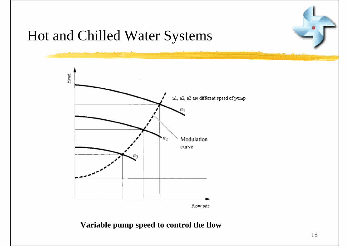
18Variable pump speed to control the flow
Hot and Chilled Water Systems

19
Change in numbers of pump to control the flow
Hot and Chilled Water Systems
20
Hot and Chilled Water Systems

21
Hot and Chilled Water Systems
EMSD Code of Practice on Pumping SystemVariable Flow Pumping systems shall be designed for variable flow of reducing system flow to 50% of design flow or less.
Exceptions: are systems where a minimum flow greater than 50% of the design flow is required for the proper operation of equipment served by the system, such as chillers.
Friction LossThe friction loss of a piping system shall not exceed 400 Pa/m.
The designer shall also consider lower friction loss for noise or erosion control.
22
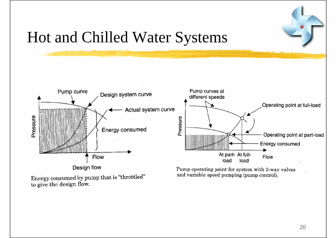
Hot and Chilled Water SystemsUse variable speed drives to vary the water flow :-
Reducing the water flow from full flow to 80% flow by turning the valves only reduces energy consumption by about 3%.
Use variable speed drives to change the speed of the pump/motor to deliver 80% flow, the energy consumption is 1/2 as it is proportional to the third power of speed.
Variable speed drives or frequency inverters, are sensitive to phase imbalance or difference in phase loads and usually induce harmonic currents due to their non-linear nature.
Phase differences are no more than 10% on circuits incorporating these devices and the system do not give rise to excessive harmonic contents.

23
Components of Water Systems
Hydronic System
Basic System
These fundamental components are
Loads Source Expansion chamber Pump Distribution system
Actual systems : valves, vents, regulators.
24
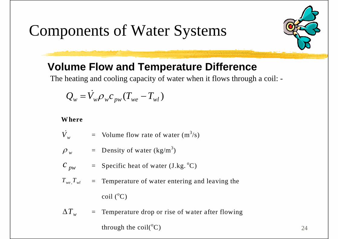
The heating and cooling capacity of water when it flows through a coil: -
)( wlwepwwww TTcVQ −= ρ&
Where
wV& = Volume flow rate of water (m3/s)
wρ = Density of water (kg/m3)
pwc = Specific heat of water (J.kg. oC)
wlwe TT , = Temperature of water entering and leaving the
coil (oC)
wTΔ = Temperature drop or rise of water after flowing
through the coil(oC)
Volume Flow and Temperature Difference
Components of Water Systems
25
The temperature of water leaving the water chiller should be no lower than 2.8°C to prevent freezing.
Performance of a chilled water system is closely related to : -
The temperature of water entering the coil (Twe), The temperature of water leaving the coil (Twl), and The difference differential (Twl-Twe)
Note also that: -
Temperature Twe directly affects the power consumption in the compressor.
The temperature differential is closely related to the volume flow of chilled water and thus the size of the water pipes and pumping power.
Components of Water Systems
Volume Flow and Temperature Difference

26
Components of Water Systems
Heating load devicesPreheat coils in central unitsHeating coils in central unitsFinned-tube radiatorsConvectorsUnit heatersFan-coil unitsWater-to-water heat exchangersRadiant heating panels
Cooling load devicesCoils in central unitsFan-coil unitsInduction unit coilsRadiant cooling panelsWater-to-water heat exchangers
27
Components of Water Systems
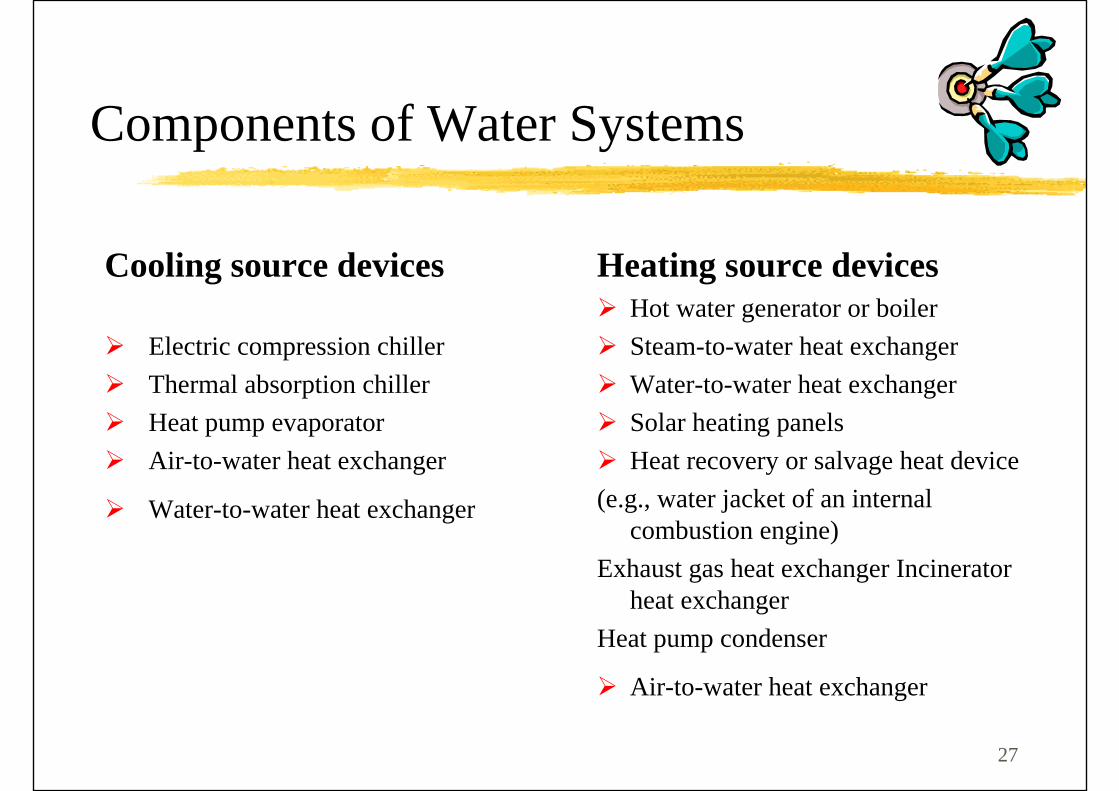
Heating source devices Hot water generator or boiler Steam-to-water heat exchanger Water-to-water heat exchanger Solar heating panels Heat recovery or salvage heat device
(e.g., water jacket of an internal combustion engine)
Exhaust gas heat exchanger Incinerator heat exchanger
Heat pump condenser
Air-to-water heat exchanger
Cooling source devices
Electric compression chiller Thermal absorption chiller Heat pump evaporator Air-to-water heat exchanger
Water-to-water heat exchanger

28
Pressure drop
Pipe erosion
Noise
Water hammer
Piping Design - Water Velocity and Pressure DropThe maximum water velocity in pipes is governed mainly by
Components of Water Systems
29
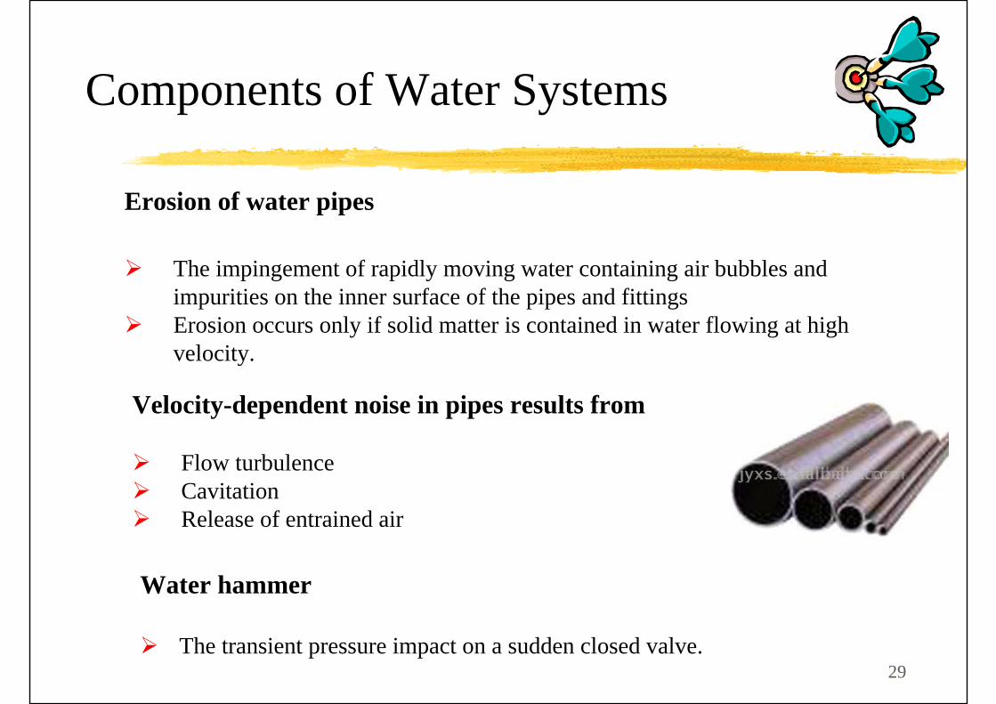
Erosion of water pipes
The impingement of rapidly moving water containing air bubbles and impurities on the inner surface of the pipes and fittings Erosion occurs only if solid matter is contained in water flowing at high velocity.
Velocity-dependent noise in pipes results from
Flow turbulenceCavitationRelease of entrained air
Water hammer
The transient pressure impact on a sudden closed valve.
Components of Water Systems
30
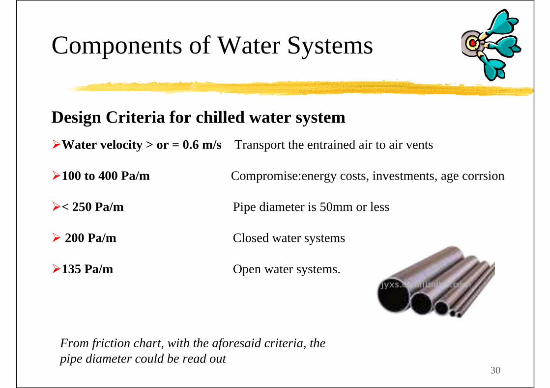
Water velocity > or = 0.6 m/s Transport the entrained air to air vents
100 to 400 Pa/m Compromise:energy costs, investments, age corrsion
< 250 Pa/m Pipe diameter is 50mm or less
200 Pa/m Closed water systems
135 Pa/m Open water systems.
Design Criteria for chilled water system
From friction chart, with the aforesaid criteria, the pipe diameter could be read out
Components of Water Systems

31
Friction Chart
Components of Water Systems
Friction Charts can easily be obtained from Guidebooks like CIBSE Guide

32
Components of Water Systems
Makeup and Fill Water SystemsGenerally, a hydronic system is filled with water through a valved connection to a water source.
Because the expansion chamber is the reference pressure point in the system, the water makeup point is usually located at or near the expansion chamber.
Chiller
Load
Expansiontank
Makeup
33
Components of Water Systems
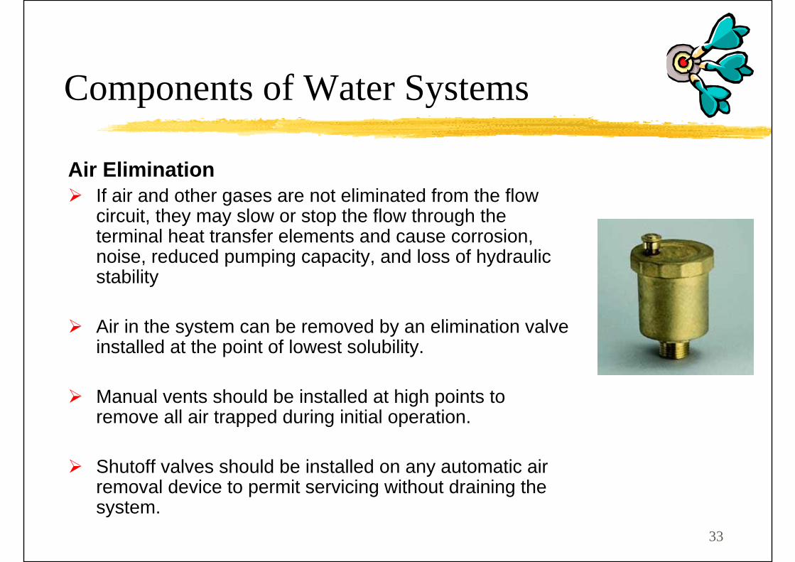
Air EliminationIf air and other gases are not eliminated from the flow circuit, they may slow or stop the flow through the terminal heat transfer elements and cause corrosion, noise, reduced pumping capacity, and loss of hydraulic stability
Air in the system can be removed by an elimination valve installed at the point of lowest solubility.
Manual vents should be installed at high points to remove all air trapped during initial operation.
Shutoff valves should be installed on any automatic air removal device to permit servicing without draining the system.

34
Components of Water Systems
Drain and ShutoffAll low points should have drains.
Separate shutoff and draining of individual equipment and circuits should be possible so that the entire system does not have to be drained to service a particular item.
Whenever a device or section of the system is isolated, and the water in that section or device could increase in temperature following isolation, overpressure safety relief protection must be provided

35
Components of Water Systems
Water Treatment
Water treatment aims to evaluate the following parameters in the chilled water system:
PH value
Turbidity
Total iron increment
Total copper increment
Total dissolved solid
Nitrite
Bacteria count

36
Piping Material
For water systems, the piping materials most widely used is :
Black Steel pipe - chilled and hot system
Galvanized(zinc-coated) – condensate drain system
Pipe JointsBlack Steel pipes by welded joints (except flange joint for large pipe with valves, etc)
Galvanized pipe (e.g. condensate pipe) with threaded fitting
Components of Water Systems

37
Working Pressure and Temperature
In a water system,
Maximum allowable working pressure and Maximum allowable temperature
A proper choice for pipes, joints, pipe fittings, valves, etc.
Components of Water Systems
38
Components of Water Systems
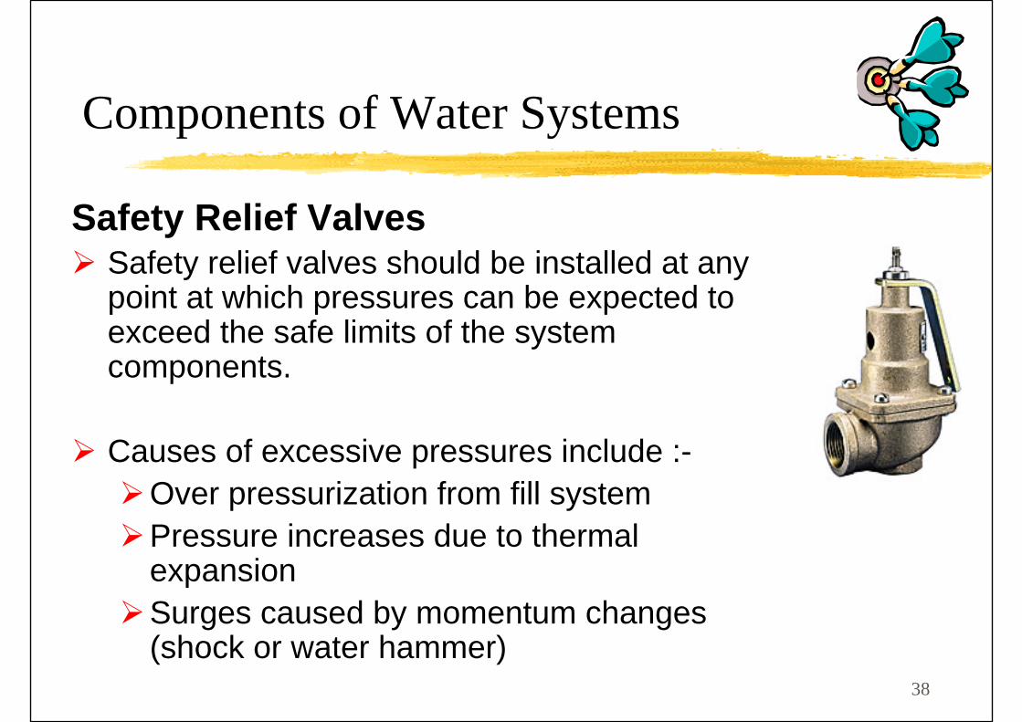
Safety Relief ValvesSafety relief valves should be installed at any point at which pressures can be expected to exceed the safe limits of the system components.
Causes of excessive pressures include :-Over pressurization from fill systemPressure increases due to thermal expansionSurges caused by momentum changes (shock or water hammer)

39
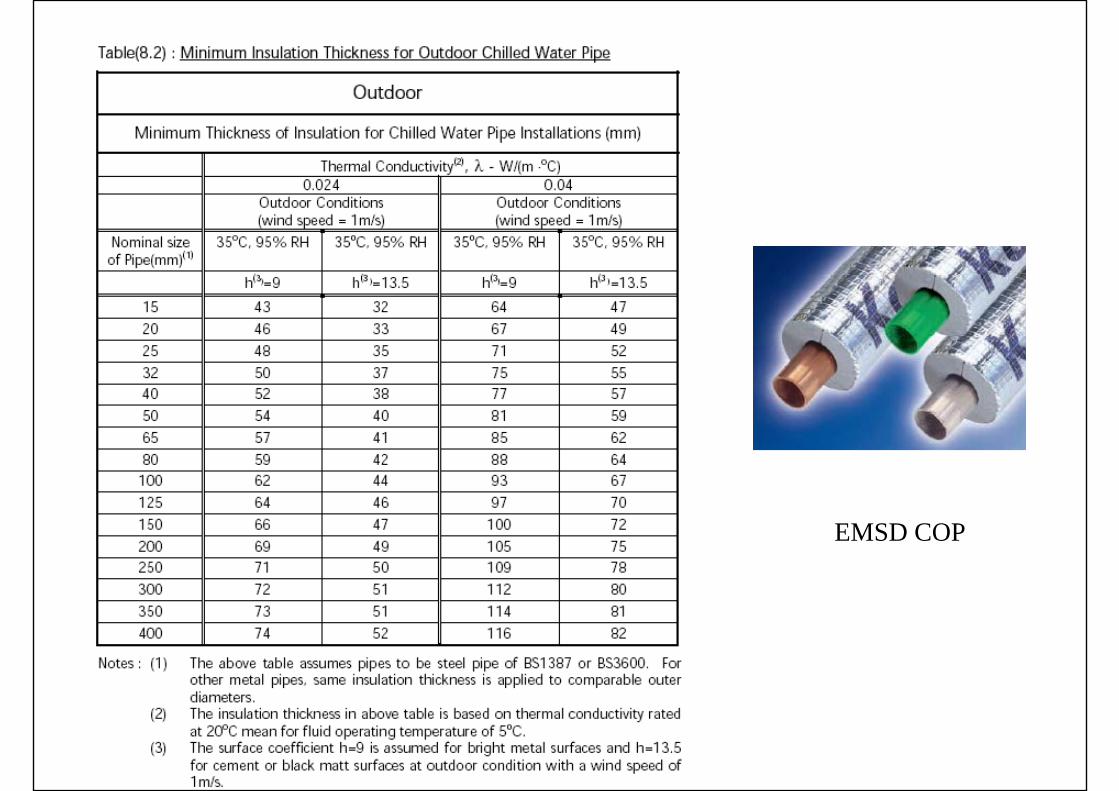
Piping Insulation
External pipe insulation should be provided to chilled and hot water system for the sake of
Energy saving, Prevention of surface condensation, and High-temperature safety protection.
The optimum thickness of the insulation of pipes depends mainly on the operating temperature of the inside water, the pipe diameter, and the types of service.
Components of Water Systems

EMSD COP
EMSD COP

42
Expansion Tank
The expansion tank provides a space into which the non-compressible liquid can expand or from which it can contract as the liquid undergoes volumetric changes with changes in temperature.
To allow for this expansion or contraction, the expansion tank provides an interface point between the system fluid and a compressible gas.
Expansion tanks are of TWO basic configurations:
An open tank (i.e., a tank open to the atmosphere); and
A diaphragm tank, in which a flexible membrane is inserted between the air and the water (another configuration of a diaphragm tank is the bladder tank).
Components of Water Systems

43
Sizing the expansion tank
Components of Water Systems

44
Components of Water Systems
Sizing the expansion tank

45
The basic construction of a valve:
A disk to open or close the water flow; A valve body to seat the disk and provide the flow passage; A stem to lift or rotate the disk, with a handwheel or a handle
Types of ValveValves are used to regulate or stop the water flow in pipes
Manually
Hand-operated valves are used to stop or isolate flow, to regulate flow, to prevent reverse flow,and to regulate water pressure.
Automatic control systems
Valves used in automatic control systems are called control valves
Components of Water Systems

46
Gate Valves.The disk of a gate valve is in the shape of a “gate” or wedge.
When the wedge is raised at the open position, a gate valve does not add much flow resistance.
Gate valves are used either fully opened or closed, an on/off arrangement.
They are often used as isolating valves for pieces of equipment or key components, such as control valves, for service during maintenance and repair.
Components of Water Systems

47
Globe Valves.A round disk or plug-type disk seated against a round port.
Globe valves have high flow resistances..
Globe valves are used to throttle and to regulate the flow.
They are sometimes called balancing valves.
Components of Water Systems

48
Check Valves.Use to prevent, or check, reverse flow.
Swing check valve
It has a hinged disk. When the water flow reverses, water pressure pushes the disk and closes the valve.
Lift check valve
In a lift check valve, upward regular flow raises the disk and opens the valve, and reverse flow pushes the disk down to its seat and stops the backflow.
Install at the discharge of pump, etc
Swing check valve
Components of Water Systems

49
Butterfly Valves.A butterfly valve has a thin rotating disk.
It varies within a quarter-turn from fully open to fully closed.
Exhibits low flow resistance when it is fully opened.
With an actuator a butterfly valve used for control purposes..
May be used for throttling purposes in addition to on/off control.
Used in large pipes.
Components of Water Systems

50
WATER CONTROL VALVES AND VALVE ACTUATORS
ValvesWater valves are used to regulate or stop water flow in a pipe either manually or by means of automatic control systems.
Water control valves adopted in water systems can modulate waterflow rates by means of automatic control systems.
Valve ActuatorsAn actuator is a device which receives an electric or pneumatic analog control signal from the controller.
It then closes or opens a valve, modulating the associated process plant, and causes the controlled variable to change toward its set point.
Valve actuators are used to position control valves.
Components of Water Systems
51
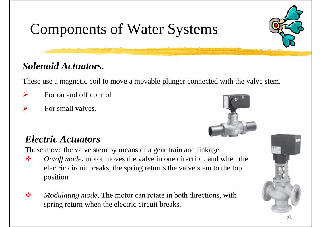
Solenoid Actuators. These use a magnetic coil to move a movable plunger connected with the valve stem.
For on and off control
For small valves.
Electric ActuatorsThese move the valve stem by means of a gear train and linkage.
On/off mode. motor moves the valve in one direction, and when the electric circuit breaks, the spring returns the valve stem to the top position
Modulating mode. The motor can rotate in both directions, with spring return when the electric circuit breaks.
Components of Water Systems
52
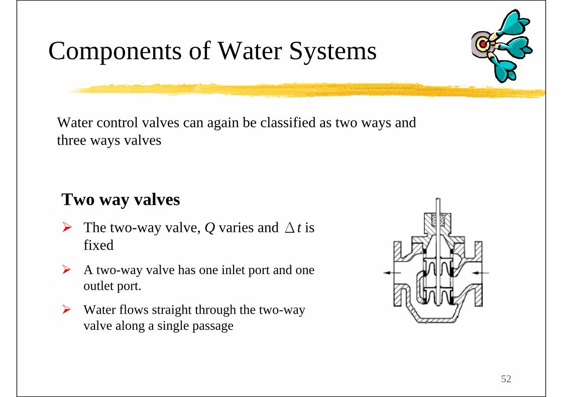
Two way valvesThe two-way valve, Q varies and Δt is fixed
A two-way valve has one inlet port and one outlet port.
Water flows straight through the two-way valve along a single passage
Components of Water Systems
Water control valves can again be classified as two ways and three ways valves

53
Three-way mixing valveThree-way valve, Δt varies and Q is fixed.
Two inlet ports and one common outlet portThe main water stream flows through the coil or boiler,
The bypass stream mixes with the main stream in the common mixing outlet port.
Three-way diverting valveOne common inlet port and two outlet ports
The supply water stream divides into two streams in the common inlet port.
The main water stream flows through the coil, and the bypass stream mixes with the main water stream after the coil.
Components of Water Systems
54
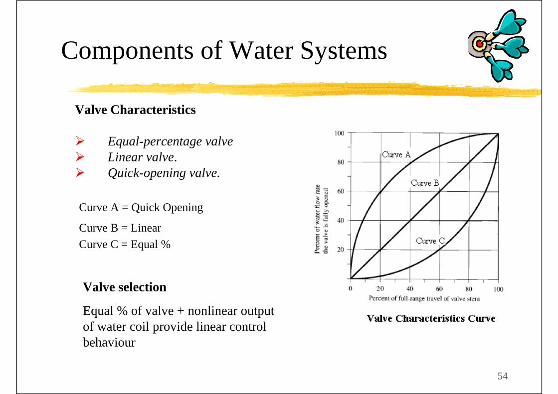
Curve A = Quick Opening
Curve B = LinearCurve C = Equal %
Valve Characteristics
Equal-percentage valveLinear valve. Quick-opening valve.
Valve selection
Equal % of valve + nonlinear output of water coil provide linear control behaviour
Components of Water Systems

55
Components of Water Systems
The Equal Percentage (curve C) characteristic is recommended for proportional control of the load flow for two-way valve;
The bypass flow port of three-way valves should have the Linear Characteristic (Curve B) to maintain a uniform flow during part-load operation.
56
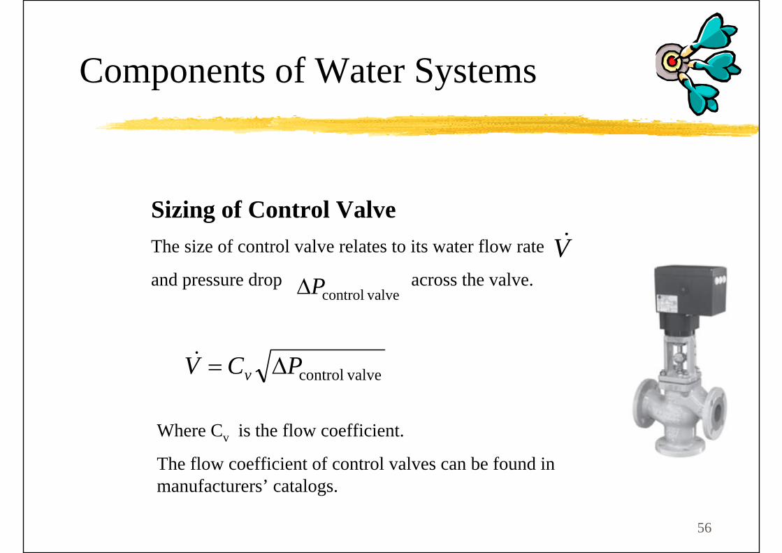
Sizing of Control ValveThe size of control valve relates to its water flow rate
and pressure drop across the valve.
valvecontrolPCV v Δ=&
Where Cv is the flow coefficient.
The flow coefficient of control valves can be found in manufacturers’ catalogs.
V&
valvecontrolPΔ
Components of Water Systems

57
Components of Water Systems
For stable control, the pressure drop in the control valve at the full-open position should be no less than one-half the pressure drop in the branch.The pressure drop at full open position for the two-way valve should equal one-half the pressure drop from A to BFor three-way valve, the full open pressure drop should be half that from C to D The pressure drop in the bypass balancing valve in the three-way valve circuit should be set to equal that in the coil (load)
Sizing of Control Valve

58
Cooling Coil
Corrugated fins can increase convective heat transfer coefficient and hence higher heat transfer rate
Components of Water Systems
59
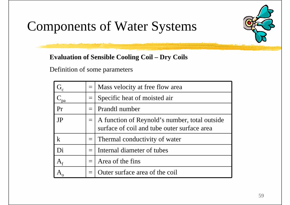
Evaluation of Sensible Cooling Coil – Dry Coils
Definition of some parameters
Gc = Mass velocity at free flow areaCpa = Specific heat of moisted airPr = Prandtl numberJP = A function of Reynold’s number, total outside
surface of coil and tube outer surface areak = Thermal conductivity of waterDi = Internal diameter of tubesAf = Area of the finsAo = Outer surface area of the coil
Components of Water Systems
60
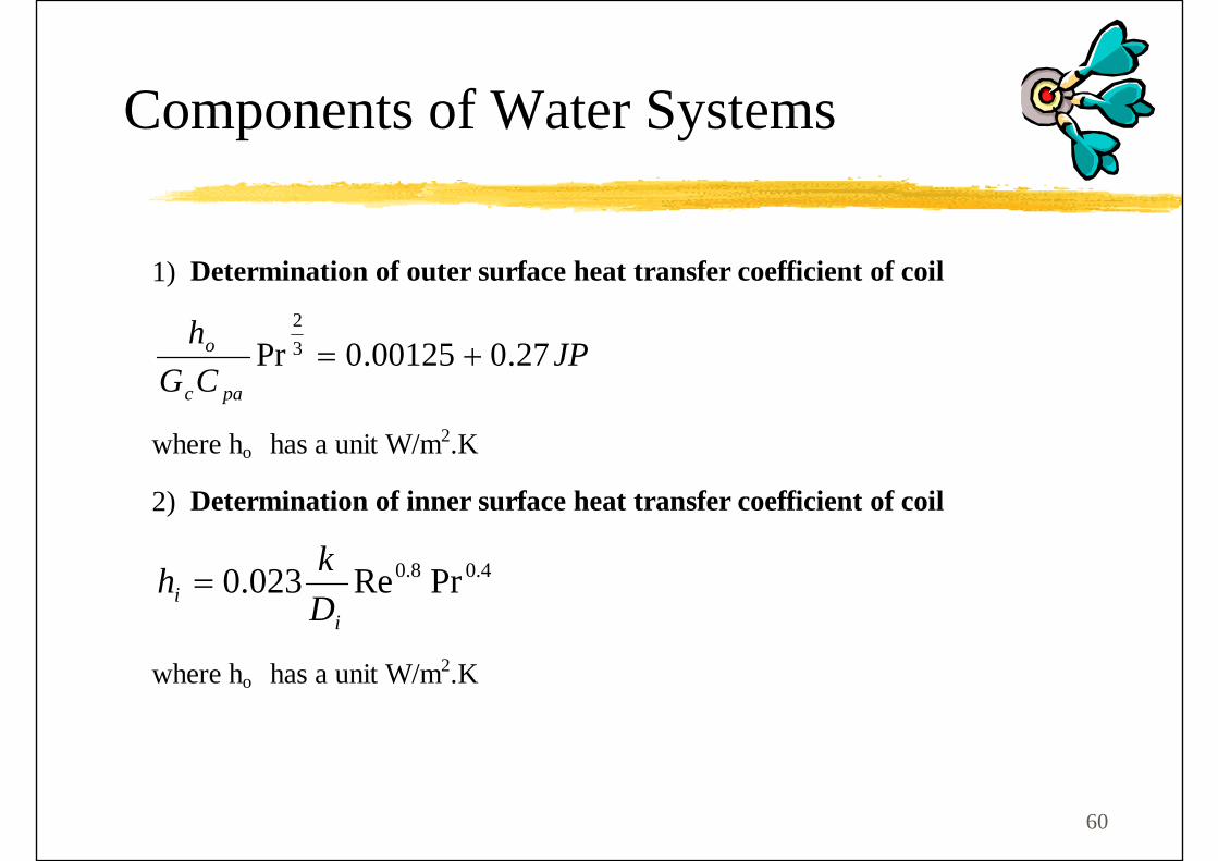
1) Determination of outer surface heat transfer coefficient of coil
JPCGh
pac
o 27.000125.0Pr 32
+=
where ho has a unit W/m2.K
2) Determination of inner surface heat transfer coefficient of coil
4.08.0 PrRe023.0i
i Dkh =
where ho has a unit W/m2.K
Components of Water Systems

61
3) Calculation of fin surface efficiency:
R-value of fin (Unit = m2K/W)
Fin efficiency fof Rh+=
11η
Surface fin efficiencyηs = )1(1 f
o
f
AA
η−⎟⎟⎠
⎞⎜⎜⎝
⎛−
Components of Water Systems

62
4) Determination of Heat capacities of air and water
Air
Heat Capacity of air (unit= kW/K) =
Face area of coil x velocity of air x density of air x specific heat of air
(Cpa= 1.02kJ/kg.K)
Water
Heat Capacity of water (unit= kW/K)=
Flow rate of water x density of water x specific heat of water
(specific heat of water Cpw = 4.2kJ/kg.K)
5) Determination on heat capacity value
w
a
CCC = if Cw > Ca or
a
w
CCC = Cw < Ca
Components of Water Systems

63
6) Determine the overall heat transfer value: -
iioosoo AhAhAU111
+=η
Hence, oo AU could be determined
7) Determine Number of Transfer Unit
Number of transfer unit, NTU= a
oo
CAU
Components of Water Systems
64
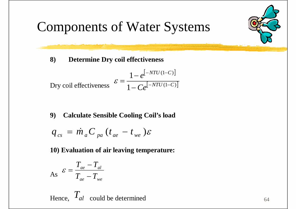
8) Determine Dry coil effectiveness
Dry coil effectiveness
[ ]
[ ])1(
)1(
11
CNTU
CNTU
Cee
−−
−−
−−
=ε
9) Calculate Sensible Cooling Coil’s load
ε)( weaepaacs ttCmq −= &
10) Evaluation of air leaving temperature:
As weae
alae
TTTT
−−
=ε
Hence, alT could be determined
Components of Water Systems

65
CENTRIFUGAL PUMPSCentrifugal pumps are the most widely for transporting chilled water, hot water, and condenser water because of their high efficiency and reliable operation.
Centrifugal pumps accelerate liquid and convert the velocity of the liquid to static head.
A typical centrifugal pump consists of an impeller rotating inside a spiral casing, a shaft, mechanical seals and bearings on both ends of the shaft, suction inlets, and a discharge outlet
Components of Water Systems

66
Types of Pumps
End Suction
Horizontal Split-casing
Vertical Inline
Components of Water Systems

67
Components of Water Systems

68
Components of Water Systems

69
Components of Water Systems

Q & A