Tiger 60 ARF - Hobbicomanuals.hobbico.com/gpm/gpma1968-manual.pdf · 3 USING THIS INSTRUCTION...
27
Ideal as a first low-wing trainer and as a terrific everyday sport plane, the Tiger 60 ARF combines docile flight characteristics with the aptitude for super-smooth, exciting aerobatics. This ARF has been designed to keep building time to a minimum; it's 90% pre-built, with a pre-assembled elevator and installed pushrod and wing guide tubes, and it features top-quality American hardware and premium covering. So read through these instructions, follow them carefully, and you'll soon be flying a tiger that "growls as you grow." The better you get the more fun it gives you! WARNING A radio-controlled model is not a toy and is not intended for persons under 16 years old. Keep this kit out of the reach of younger children, as it contains parts that could be dangerous. A radio- controlled model is capable of causing serious bodily injury and property damage. It is the buyer's responsibility to assemble this aircraft correctly and to properly install the motor, radio, and all other equipment. Test and fly the finished model only in the presence and with the assistance of another experienced R/C flyer. The model must always be operated and flown using great care and common sense, as well as in accordance with the Safety Code of the Academy of Model Aeronautics (5151 Memorial Drive, Muncie, IN 47302, 1-800-435-9262). We suggest you join the AMA and become prop- erly insured prior to flying this model. Also, consult with the AMA or your local hobby dealer to find an experienced instructor in your area. Per the Federal Communications Commission, you are required to use only those radio frequencies specified "for Model Aircraft." LIMITED WARRANTY Carl Goldberg Products has inspected and certified the components of this aircraft. The company urges the buyer to perform his own inspection, prior to assembly, and to immediately request a replacement of any parts he believes to be defective for their intended use. The company warrants replacement of any such components, provided the buyer requests such replacement with- in a period of one year from the date of purchase and provided the defective part is returned, if so requested by the company. No other warranty, expressed or implied, is made by the company with respect to this kit. The buyer acknowledges and under- stands that it is his responsibility to carefully assemble the finished flying model airplane and to fly it safely. The buyer hereby assumes full responsibility for the risk and all liability for personal or property damage or injury arising out of the buyer's use of the components of this kit. INSTRUCTIONS Tiger 60 ARF © Copyright 2002 Carl Goldberg Products LTD.
Transcript of Tiger 60 ARF - Hobbicomanuals.hobbico.com/gpm/gpma1968-manual.pdf · 3 USING THIS INSTRUCTION...
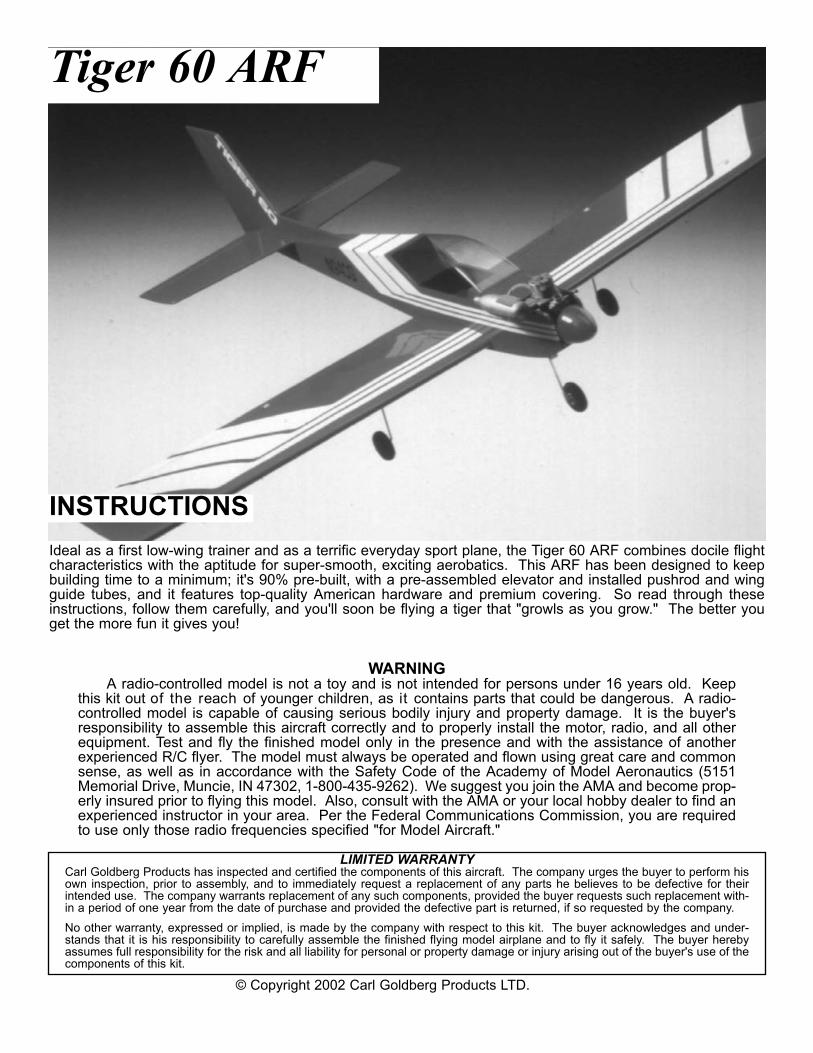
Ideal as a first low-wing trainer and as a terrific everyday sport plane, the Tiger 60 ARF combines docile flightcharacteristics with the aptitude for super-smooth, exciting aerobatics. This ARF has been designed to keepbuilding time to a minimum; it's 90% pre-built, with a pre-assembled elevator and installed pushrod and wingguide tubes, and it features top-quality American hardware and premium covering. So read through theseinstructions, follow them carefully, and you'll soon be flying a tiger that "growls as you grow." The better youget the more fun it gives you!
WARNINGA radio-controlled model is not a toy and is not intended for persons under 16 years old. Keep
this kit out of the reach of younger children, as it contains parts that could be dangerous. A radio-controlled model is capable of causing serious bodily injury and property damage. It is the buyer'sresponsibility to assemble this aircraft correctly and to properly install the motor, radio, and all otherequipment. Test and fly the finished model only in the presence and with the assistance of anotherexperienced R/C flyer. The model must always be operated and flown using great care and commonsense, as well as in accordance with the Safety Code of the Academy of Model Aeronautics (5151Memorial Drive, Muncie, IN 47302, 1-800-435-9262). We suggest you join the AMA and become prop-erly insured prior to flying this model. Also, consult with the AMA or your local hobby dealer to find anexperienced instructor in your area. Per the Federal Communications Commission, you are requiredto use only those radio frequencies specified "for Model Aircraft."
LIMITED WARRANTYCarl Goldberg Products has inspected and certified the components of this aircraft. The company urges the buyer to perform hisown inspection, prior to assembly, and to immediately request a replacement of any parts he believes to be defective for theirintended use. The company warrants replacement of any such components, provided the buyer requests such replacement with-in a period of one year from the date of purchase and provided the defective part is returned, if so requested by the company. No other warranty, expressed or implied, is made by the company with respect to this kit. The buyer acknowledges and under-stands that it is his responsibility to carefully assemble the finished flying model airplane and to fly it safely. The buyer herebyassumes full responsibility for the risk and all liability for personal or property damage or injury arising out of the buyer's use of thecomponents of this kit.
INSTRUCTIONS
Tiger 60 ARF
© Copyright 2002 Carl Goldberg Products LTD.
2
ITEMS NEEDED TO COMPLETE THIS AIRCRAFT
1 RADIO GUIDANCE SYSTEM (4 CHANNELMINIMUM REQUIRED) 5 SERVOS
2 6” AILERON SERVO EXTENSION WIRES1 Y-HARNESS1 ENGINE .60-.65 2-CYCLE OR .70-.80 4-
CYCLE, AND MUFFLER1 ZAP ACCELERATOR1 2 OZ. BOTTLE ZAP-A-GAP medium CA1 1/2 OZ. BOTTLE ZAP Super Thin CA1 BOTTLE ZAP 30 minute and/or 5 minute
epoxy. 1 DuBro Switch mount Part # 203 1 Foam rubber 1/2”x8”x12”
TOOLS AND SUPPLIES FOR ASSEMBLY.MODELING OR UTILITY KNIFEWORK SURFACE (24" X70")ELECTRIC DRILL1/16”,5/64” 3/32”,1/8", 5/32”, 1/4” DRILLBITSSMALL STANDARD & PHILLIPS SCREW-DRIVERSMASKING TAPENEEDLE NOSE PLIERS36” RULER OR TAPE MEASUREFLEXIBLE STRAIGHT-EDGET-SQUARE30-60-90° x 6" TRIANGLESOFT PENCILA FEW STRAIGHT OR "T" PINSADJUSTABLE WRENCHWIRE CUTTER OPTIONAL HEAT GUN/COVERING IRONACID BRUSH
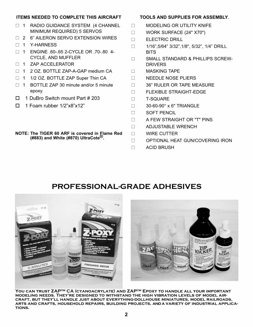
You can trust ZAP™ CA (cyanoacrylate) and ZAP™ Epoxy to handle all your importantmodeling needs. They're designed to withstand the high vibration levels of model air-craft, but they'll handle just about everything-dollhouse miniatures, model railroads,arts and crafts, household repairs, building projects, and a variety of industrial applica-tions.
PROFESSIONAL-GRADE ADHESIVES
NOTE: The TIGER 60 ARF is covered in Flame Red(#883) and White (#870) UltraCote®.

3
USING THIS INSTRUCTION MANUALBefore you begin assembling your TIGER 60 ARF, takesome time to read through this entire instruction book. Itis designed to take you step-by-step through the processand to give you added information on engine and radioselection and set-up, balancing your aircraft, and flyingyour model. The time you spend will speed the assemblyprocess and help you avoid problems.
PREPARING FOR ASSEMBLYYou will need a work area of approximately 24 x 70" which hasbeen covered to protect it from adhesive, as well as cuts andother damage. Many people cover their work area with asheet of dry wall (sheet rock) and/or waxed paper t o pre-vent Zap CA and Epoxy from ruining the work surface.
CONSTRUCTION TIPSIMPORTANT: ALWAYS READ A FEW STEPS AHEAD.This will alert you to coming instructions and will help youplan accordingly.
Using the Parts Identification section, familiarize yourselfwith the various items included in your kit box.As you work, CHECK OFF EACH STEP in the box pro-vided, so that you are sure you do not forget anything.Do not hesitate to ask questions. Your local hobby deal-er and area flyers will most likely be happy to help, as theywant you to have a successful flying experience. You mayalso receive technical assistance from Carl GoldbergProducts via e-mail (carlgoldbergproducts.com) or by tele-phone 678-450-0085.
INTRODUCTION
ADHESIVES & GLUING TECHNIQUESThe ZAP family of adhesives are specially formulated tofirmly glue the plywood, hardwood, and balsa used in yourmodel and to withstand the vibration and stresses of highperformance flight. ZAP A GAP CA is perfect for mostjobs. However, there are times, such as when you areinstalling the stabilizer and fin on the fuselage and wantmore set-up time for careful alignment and positioning,then you should use ZAP ZPOXY™.. Occasionally, youalso will want to use ZAP Super Thin™, which "wicks" intothe surrounding areas. Aliphatic resin glue or similarwater-based glues can also be used, but they will add tothe assembly time because they dry so much more slow-ly than ZAP A GAP. Remember, whenever using any CA,
you must be careful to read instructions thoroughly, asyou will have only seconds for positioning of parts. Besure to trial fit parts together before gluing. Also, neveruse watery THIN type CA glue for gluing plywood andhardwood parts. Thin CA's do not adequately bond theseareas.
CAUTIONSome people may experience an allergic reaction whenexposed to fumes from CA glue or epoxy. As with paints,thinners, and solvents, it is always important to use gluesonly where there is adequate ventilation to carry fumesaway. A fan is recommended. Also, special care must betaken when using CA, as it will bond skin as well as othersurfaces. ZAP CA remover is a CA solvent whichremoves hardened glue from fingers and softens gluedjoints for repositioning. Before using any CA, carefullyread all label precautions. When using CA, protectiveeye-wear and care in keeping the glue away from the faceis highly recommended. If CA does happen to get into theeye, hold lid open and flush with water only. Seek imme-diate medical attention.
COVERINGThe TIGER 60 ARF is covered in premium iron on film.It is not uncommon for ARF's to develop a few wrinkles intransit. If this is true of your model, the situation is easilycorrected. Before you begin putting the pieces together,run over the surface of each section with an iron (eitherspecially designed for airplane use or the more cumber-some household iron) or use a modeling heat gun. Applythe heat (set at about 350° F), following along with a softcloth and pressing down on the covering as you goaround. This will more firmly set the covering adhesiveinto the wood and keep your aircraft covering tight andsmooth in the future.One of the great advantages of film is that it can beapplied over itself without causing gas bubbles. Thisallows you to repair your aircraft, as well as to customizeit in a number of ways. If, due to a flight mishap, you geta hole or similar covering damage, simply trim away theragged edges and then apply a patch, following the direc-tions that come with replacement film , which is availableat your hobby dealer. In case of a major crash, wherelarge amounts of the film must be replaced, heat thedamaged covering and then slowly peel up. If you areapplying sufficient heat, the film will come up easily andleave no color on the wood.
4
RADIO EQUIPMENT & CARE
There are many fine radio systems on the market. Yourlocal hobby dealer and club members are good sourcesof information on equipment and its suitability for variousprojects. It is recommended that you speak to thembefore making a final choice.
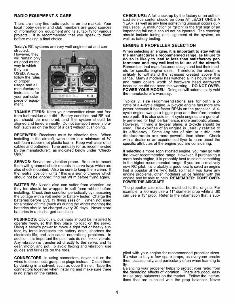
Today's RC systems are very well engineered and con-structed.However, theywill remain onlyas good as theway in whichthey areUSED. Alwaysfollow the rulesof properusage and allmanufacturer'sinstructions foryour particularpiece of equip-ment.
TRANSMITTERS: Keep your transmitter clean and freefrom fuel residue and dirt. Battery condition and RF out-put should be monitored, and the system should bealigned and tuned annually. Do not transport under vibra-tion (such as on the floor of a car) without cushioning.
RECEIVERS: Receivers must be vibration free. Wheninstalling in the aircraft, wrap them in a minimum of ¼"soft foam rubber (not plastic foam). Keep well clear of allcables and batteries. Tune annually (or as recommendedby the manufacturer), as indicated below under "Check-Ups."
SERVOS: Servos are vibration prone. Be sure to mountthem with grommet shock mounts in servo trays which arealso shock mounted. Also be sure to keep them clean. Ifthe neutral position "drifts," this is a sign of change whichshould not be ignored; find out WHY before flying again.
BATTERIES: Nicads also can suffer from vibration, sothey too should be wrapped in soft foam rubber beforeinstalling. Check their condition periodically by measuringthe voltage with a volt meter or battery tester. Charge thebatteries before EVERY flying session. When not usedfor a period of time (such as during the winter months) thebatteries should be charged every 30 days. Never storebatteries in a discharged condition.
PUSHRODS: Obviously, pushrods should be installed tooperate freely, so that they place no load on the servo.Using a servo's power to move a tight rod or heavy sur-face by force increases the battery drain, shortens theelectronic life, and can cause neutralizing problems. Inaddition, it is important the pushrods do not flex or vibrate.Any vibration is transferred directly to the servo, and itsgear, motor, and pot. To avoid flexing and vibration, useguides and fairleads on the rods.
CONNECTORS: In using connectors, never pull on thewires to disconnect; grasp the plugs instead. Clean themby dunking in a solvent, such as dope thinner. Tape theconnectors together when installing and make sure thereis no strain on the cables.
CHECK-UPS: A full check-up by the factory or an author-ized service center should be done AT LEAST ONCE AYEAR, as well as any time something unusual occurs dur-ing usage. A malfunction or "glitch" is the first sign of animpending failure; it should not be ignored. The checkupshould include tuning and alignment of the system, aswell as battery testing.
ENGINE & PROPELLER SELECTIONWhen selecting an engine, it is important to stay withinthe manufacturer’s recommended range, as failure todo so is likely to lead to less than satisfactory per-formance and may well lead to failure of the aircraft.Remember, that manufacturers design and test their mod-els for specific engine sizes. Therefore, the aircraft isunlikely to withstand the stresses created above thisrange. Many a modeler has watched all his hours of workand many dollars worth of hardware head earthwardbecause he did not heed this warning: DO NOT OVER-POWER YOUR MODEL! Doing so will automatically voidthe manufacturer’s warranty.
Typically, size recommendations are for both a 2-cycle or a 4-cycle engine. A 2-cycle engine has more rawpower because it has faster RPMs on the propeller. A 4-cycle engine swings a bigger prop and therefore createsmore pull. It is also quieter. 4-cycle engines are general-ly preferred for high performance, more aerobatic planes.However, if flying a tri-gear plane, a 2-cycle should beused. The expense of an engine is usually related toits efficiency. Some engines of similar cubic inchdisplacements are more powerful than others. Checkwith a dealer or an experienced flyer to learn about thespecific attributes of the engine you are considering.
If selecting a more sophisticated engine, you may go withthe lower recommended range However, if purchasing amore basic engine, it is probably best to select somethingin the higher recommended range. If you are a relativelynew RC pilot, it's probably a good idea to select an enginethat is popular at the flying field, so that if you have anyengine problems, other modelers will be familiar with theengine and be able to help. REMEMBER: DON'T OVER-POWER THE AIRCRAFT!The propeller size must be matched to the engine. Forexample, a .60 may use a 11" diameter prop while a .80can use a 13" prop. Refer to the information that is sup-
plied with your engine for recommended propeller sizes.It's wise to buy a few spare props, as everyone breaksthem occasionally, and particularly often when learning tofly.Balancing your propeller helps to protect your radio fromthe damaging effects of vibration. There are good, easyto use prop balancers on the market. Follow the instruc-tions that are supplied with the prop balancer. Never
5
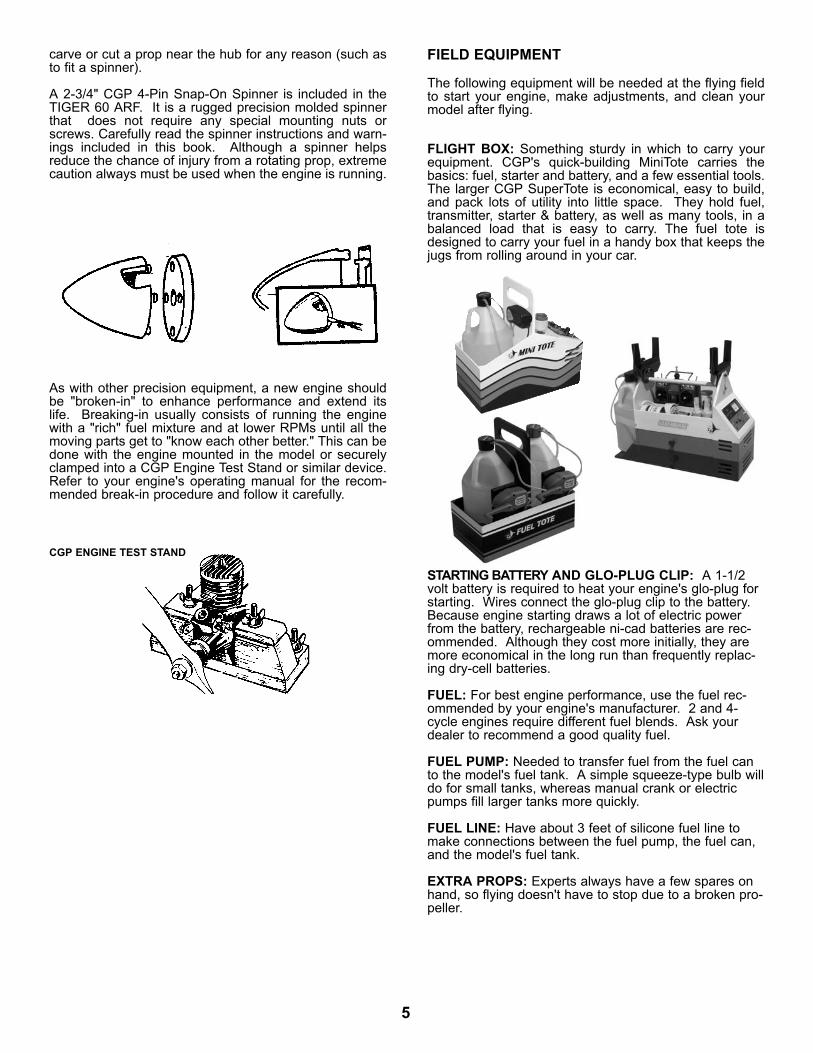
carve or cut a prop near the hub for any reason (such asto fit a spinner).
A 2-3/4" CGP 4-Pin Snap-On Spinner is included in theTIGER 60 ARF. It is a rugged precision molded spinnerthat does not require any special mounting nuts orscrews. Carefully read the spinner instructions and warn-ings included in this book. Although a spinner helpsreduce the chance of injury from a rotating prop, extremecaution always must be used when the engine is running.
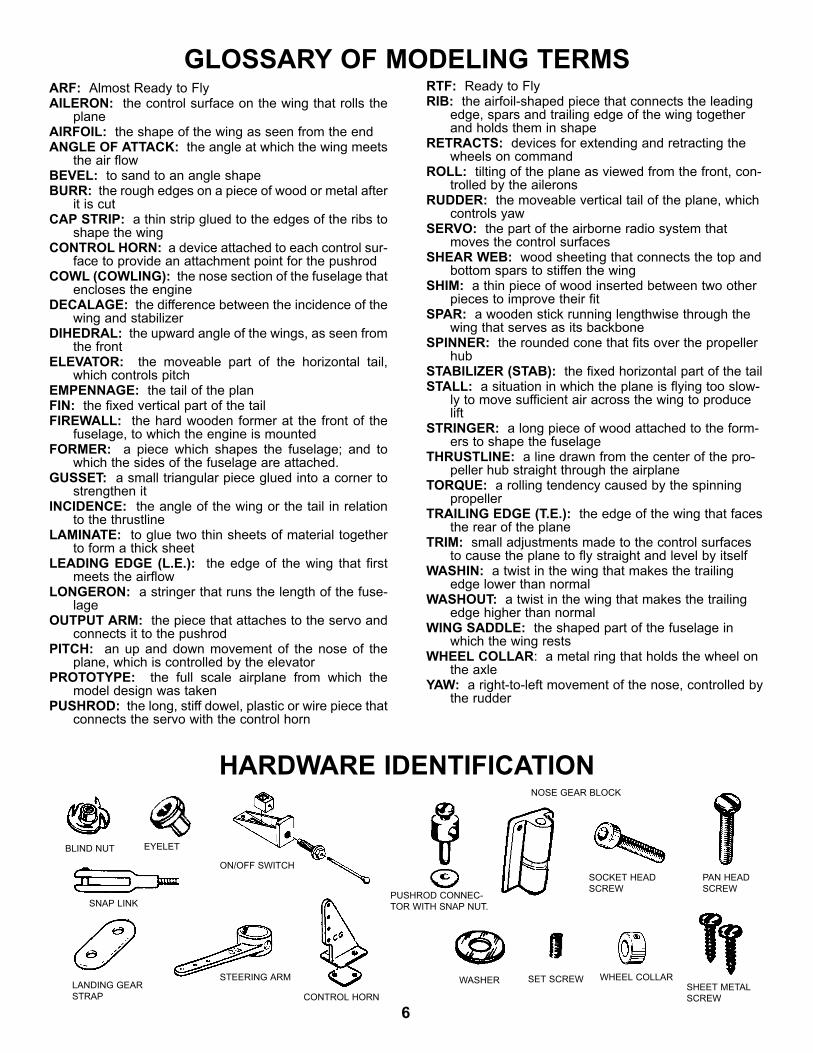
As with other precision equipment, a new engine shouldbe "broken-in" to enhance performance and extend itslife. Breaking-in usually consists of running the enginewith a "rich" fuel mixture and at lower RPMs until all themoving parts get to "know each other better." This can bedone with the engine mounted in the model or securelyclamped into a CGP Engine Test Stand or similar device.Refer to your engine's operating manual for the recom-mended break-in procedure and follow it carefully.
STARTING BATTERY AND GLO-PLUG CLIP: A 1-1/2volt battery is required to heat your engine's glo-plug forstarting. Wires connect the glo-plug clip to the battery.Because engine starting draws a lot of electric powerfrom the battery, rechargeable ni-cad batteries are rec-ommended. Although they cost more initially, they aremore economical in the long run than frequently replac-ing dry-cell batteries.
FUEL: For best engine performance, use the fuel rec-ommended by your engine's manufacturer. 2 and 4-cycle engines require different fuel blends. Ask yourdealer to recommend a good quality fuel.
FUEL PUMP: Needed to transfer fuel from the fuel canto the model's fuel tank. A simple squeeze-type bulb willdo for small tanks, whereas manual crank or electricpumps fill larger tanks more quickly.
FUEL LINE: Have about 3 feet of silicone fuel line tomake connections between the fuel pump, the fuel can,and the model's fuel tank.
EXTRA PROPS: Experts always have a few spares onhand, so flying doesn't have to stop due to a broken pro-peller.
CGP ENGINE TEST STAND
FIELD EQUIPMENT
The following equipment will be needed at the flying fieldto start your engine, make adjustments, and clean yourmodel after flying.
FLIGHT BOX: Something sturdy in which to carry yourequipment. CGP's quick-building MiniTote carries thebasics: fuel, starter and battery, and a few essential tools.The larger CGP SuperTote is economical, easy to build,and pack lots of utility into little space. They hold fuel,transmitter, starter & battery, as well as many tools, in abalanced load that is easy to carry. The fuel tote isdesigned to carry your fuel in a handy box that keeps thejugs from rolling around in your car.
6
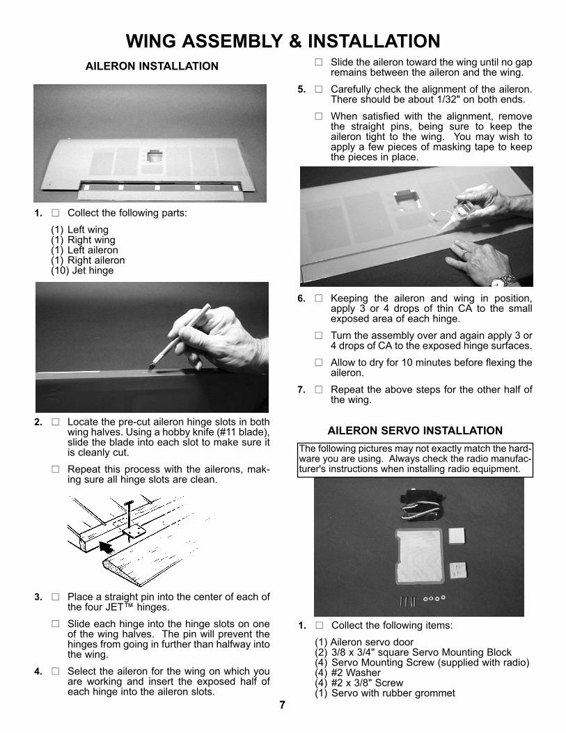
HARDWARE IDENTIFICATION
GLOSSARY OF MODELING TERMSARF: Almost Ready to FlyAILERON: the control surface on the wing that rolls the
planeAIRFOIL: the shape of the wing as seen from the endANGLE OF ATTACK: the angle at which the wing meets
the air flowBEVEL: to sand to an angle shapeBURR: the rough edges on a piece of wood or metal after
it is cutCAP STRIP: a thin strip glued to the edges of the ribs to
shape the wingCONTROL HORN: a device attached to each control sur-
face to provide an attachment point for the pushrodCOWL (COWLING): the nose section of the fuselage that
encloses the engineDECALAGE: the difference between the incidence of the
wing and stabilizerDIHEDRAL: the upward angle of the wings, as seen from
the frontELEVATOR: the moveable part of the horizontal tail,
which controls pitchEMPENNAGE: the tail of the planFIN: the fixed vertical part of the tailFIREWALL: the hard wooden former at the front of the
fuselage, to which the engine is mountedFORMER: a piece which shapes the fuselage; and to
which the sides of the fuselage are attached.GUSSET: a small triangular piece glued into a corner to
strengthen itINCIDENCE: the angle of the wing or the tail in relation
to the thrustlineLAMINATE: to glue two thin sheets of material together
to form a thick sheetLEADING EDGE (L.E.): the edge of the wing that first
meets the airflowLONGERON: a stringer that runs the length of the fuse-
lageOUTPUT ARM: the piece that attaches to the servo and
connects it to the pushrodPITCH: an up and down movement of the nose of the
plane, which is controlled by the elevatorPROTOTYPE: the full scale airplane from which the
model design was takenPUSHROD: the long, stiff dowel, plastic or wire piece that
connects the servo with the control horn
RTF: Ready to FlyRIB: the airfoil-shaped piece that connects the leading
edge, spars and trailing edge of the wing togetherand holds them in shape
RETRACTS: devices for extending and retracting thewheels on command
ROLL: tilting of the plane as viewed from the front, con-trolled by the ailerons
RUDDER: the moveable vertical tail of the plane, whichcontrols yaw
SERVO: the part of the airborne radio system thatmoves the control surfaces
SHEAR WEB: wood sheeting that connects the top andbottom spars to stiffen the wing
SHIM: a thin piece of wood inserted between two otherpieces to improve their fit
SPAR: a wooden stick running lengthwise through thewing that serves as its backbone
SPINNER: the rounded cone that fits over the propellerhub
STABILIZER (STAB): the fixed horizontal part of the tailSTALL: a situation in which the plane is flying too slow-
ly to move sufficient air across the wing to producelift
STRINGER: a long piece of wood attached to the form-ers to shape the fuselage
THRUSTLINE: a line drawn from the center of the pro-peller hub straight through the airplane
TORQUE: a rolling tendency caused by the spinningpropeller
TRAILING EDGE (T.E.): the edge of the wing that facesthe rear of the plane
TRIM: small adjustments made to the control surfacesto cause the plane to fly straight and level by itself
WASHIN: a twist in the wing that makes the trailingedge lower than normal
WASHOUT: a twist in the wing that makes the trailingedge higher than normal
WING SADDLE: the shaped part of the fuselage inwhich the wing rests
WHEEL COLLAR: a metal ring that holds the wheel onthe axle
YAW: a right-to-left movement of the nose, controlled bythe rudder
BLIND NUT EYELET
PUSHROD CONNEC-TOR WITH SNAP NUT.
NOSE GEAR BLOCK
SNAP LINK
LANDING GEARSTRAP
STEERING ARM
CONTROL HORN
ON/OFF SWITCHSOCKET HEADSCREW
WHEEL COLLAR
PAN HEADSCREW
SHEET METALSCREW
SET SCREWWASHER
7
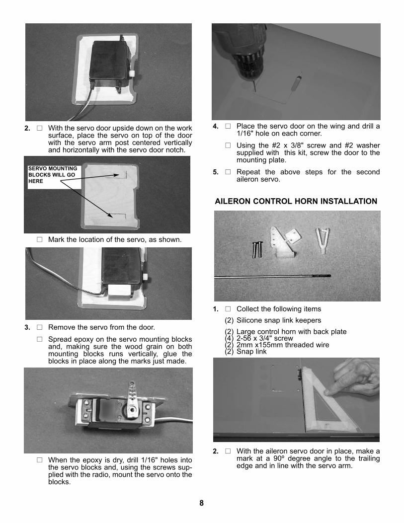
WING ASSEMBLY & INSTALLATIONAILERON INSTALLATION
1. Collect the following parts:(1) Left wing(1) Right wing(1) Left aileron(1) Right aileron(10) Jet hinge
2. Locate the pre-cut aileron hinge slots in bothwing halves. Using a hobby knife (#11 blade),slide the blade into each slot to make sure itis cleanly cut.Repeat this process with the ailerons, mak-ing sure all hinge slots are clean.
3. Place a straight pin into the center of each ofthe four JET™ hinges.Slide each hinge into the hinge slots on oneof the wing halves. The pin will prevent thehinges from going in further than halfway intothe wing.
4. Select the aileron for the wing on which youare working and insert the exposed half ofeach hinge into the aileron slots.
Slide the aileron toward the wing until no gapremains between the aileron and the wing.
5. Carefully check the alignment of the aileron.There should be about 1/32" on both ends.When satisfied with the alignment, removethe straight pins, being sure to keep theaileron tight to the wing. You may wish toapply a few pieces of masking tape to keepthe pieces in place.
6. Keeping the aileron and wing in position,apply 3 or 4 drops of thin CA to the smallexposed area of each hinge.Turn the assembly over and again apply 3 or4 drops of CA to the exposed hinge surfaces.Allow to dry for 10 minutes before flexing theaileron.
7. Repeat the above steps for the other half ofthe wing.
AILERON SERVO INSTALLATIONThe following pictures may not exactly match the hard-ware you are using. Always check the radio manufac-turer's instructions when installing radio equipment.
1. Collect the following items:(1) Aileron servo door(2) 3/8 x 3/4" square Servo Mounting Block(4) Servo Mounting Screw (supplied with radio)(4) #2 Washer(4) #2 x 3/8" Screw(1) Servo with rubber grommet
8
2. With the servo door upside down on the worksurface, place the servo on top of the doorwith the servo arm post centered verticallyand horizontally with the servo door notch.
Mark the location of the servo, as shown.
3. Remove the servo from the door.Spread epoxy on the servo mounting blocksand, making sure the wood grain on bothmounting blocks runs vertically, glue theblocks in place along the marks just made.
4. Place the servo door on the wing and drill a1/16" hole on each corner. Using the #2 x 3/8" screw and #2 washersupplied with this kit, screw the door to themounting plate.
5. Repeat the above steps for the secondaileron servo.
AILERON CONTROL HORN INSTALLATION
1. Collect the following items(2) Silicone snap link keepers(2) Large control horn with back plate(4) 2-56 x 3/4" screw(2) 2mm x155mm threaded wire(2) Snap link
2. With the aileron servo door in place, make amark at a 90º degree angle to the trailingedge and in line with the servo arm.
When the epoxy is dry, drill 1/16" holes intothe servo blocks and, using the screws sup-plied with the radio, mount the servo onto theblocks.
SERVO MOUNTINGBLOCKS WILL GOHERE

9
3. Position the control horn so that the snap linkholes are right next to the hinge line, asshown.
4. Using a 5/64" drill bit, make a pilot hole ineach screw location.Mount the control horn with the 2-56 x 3/4"screws.
5. Thread the 2mm x 155mm rod onto the snaplink. Make sure the rod shows in the center ofthe snap link.Place the snap link in the second hole fromthe top on the control horn. Slide the siliconekeeper in place
6. Make sure the aileron is in neutral (level)position, mark where the wire meets the holeon the servo arm.Remove the wire and cut it about 1/2"beyond the mark.
Make a 90º bend (or a "z" bend, if preferred)in the wire and insert the wire in the servoarm.Secure the wire with a snap nut and then puta drop of ZAP CAt™ on the snap nut tomake sure it stays in place.
PLACE CONTROL HORN AT HINGE LINE
2-56 X 3/4" SCREWS
SNAP LINK
CONTROLHORN
SERVO EXTENSION INSTALLATION
1. Gather the following items:(2) 6" Extension wires(1) Wing
2. Remove the servo door and plug one 6"extension wire into the servo. If the extension is not long enough to reachto the center of the wing, add an additionalextension to each extension wire for correctlength.
IMPORTANT! To ensure that any connections locatedinside the wing will not come loose, either when thewires are pulled, or during flying, always tape themsecurely together with electrical tape.
3. Making sure to use the correct servo for theopening, attach the servo wire to the 6"extension and securely tape the connection.Push the extension wire into the tube in thewing until it comes out hole near the centerof the wing.

10
5. Repeat these steps for the other half of thewing, so that both servo extensions are exit-ing the holes in the center of the wing.
WING INSTALLATION ON FUSELAGE
3. Working with the fuselage upside down,insert a 6-32 blind nut into each hole in thewing mounting blocks, with the teeth pointingupward into the blocks.Temporarily insert a 6-32 x 1" screw intoeach hole on the other side of the mountingblock and draw the blind nut teeth down intothe wood.When the blind nuts are firmly seated in thewing mount blocks, remove the screws.
FUSE SHOWN UPSIDE DOWN
SCREW
WING
BLIND NUT
4. Gently prodding the covering, locate the holenext to the center of the of the wing, close tothe trailing edge.Carefully remove the covering OVER THEHOLE in the wing on both the top and thebottom.Do the same to the other wing panel.
5. Insert the large aluminum tube into one winghalf and push the tube into the wing until itstops. Then insert the small aluminum tubeinto the small hole till it stops. Then slide thewing halves together.
4. Grasping the extension in the hole, SLOWLYpull until the end of the 6" extension comesout of the hole. Tape the extension securely to the wing, sothat it will not slide back in while you areworking.Screw the servo door into the wing.
NOTE: If the covering on your wing has loosened intransit, refer to the covering section of the"INTRODUCTION" before continuing.
1. Collect the following items:(1) Right wing(1) Left wing(2) 5/16 x 1-1/2" dowel(1) Large aluminum tube(1) Small aluminum Tube(2) 6-32 x 1-1/2 Socket Head bolt(2) 6-32 Blind nut(2) #6 x 3/4” washer
2. Using ZAP ZPOXY™, mount the 5/16 x 1-3/4” dowels into the holes in the leading edgeof the wing. Make sure to leave about 1/2” ofdowel sticking out of the front of the wing. Youmay wish to slightly taper the exposed dowelends for ease of insertion into the fuse holes.

11
4. Insert the wing into the wing saddle of thefuselage by sliding the dowels in the front ofthe wing into the holes in the former just for-ward of the wing saddle.
Align the holes in the wing bolt plate over theholes in the wing.Insert two #6-32 x 1-1/2" socket head screwsand the #6 x 3/4" washers through the boltplate and the wing and then begin to screwinto the blind nut in the fuselage. Screw downuntil the screws are tight.
12
TAIL ASSEMBLY & INSTALLATION
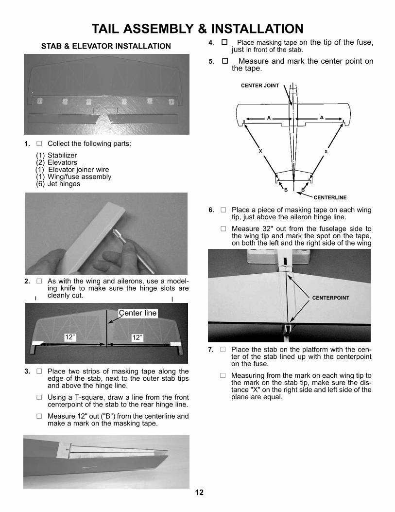
1. Collect the following parts:(1) Stabilizer(2) Elevators(1) Elevator joiner wire(1) Wing/fuse assembly(6) Jet hinges
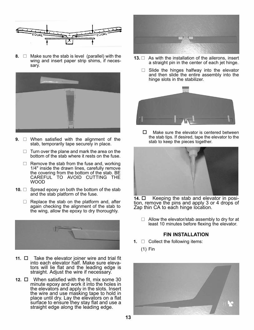
6. Place a piece of masking tape on each wingtip, just above the aileron hinge line.Measure 32" out from the fuselage side tothe wing tip and mark the spot on the tape,on both the left and the right side of the wing
2. As with the wing and ailerons, use a model-ing knife to make sure the hinge slots arecleanly cut.
STAB & ELEVATOR INSTALLATION
CENTER JOINT
CENTERLINE
3. Place two strips of masking tape along theedge of the stab, next to the outer stab tipsand above the hinge line.Using a T-square, draw a line from the frontcenterpoint of the stab to the rear hinge line.Measure 12" out ("B") from the centerline andmake a mark on the masking tape.
12”12”
Center line
4. Place masking tape on the tip of the fuse,just in front of the stab.
5. Measure and mark the center point onthe tape.
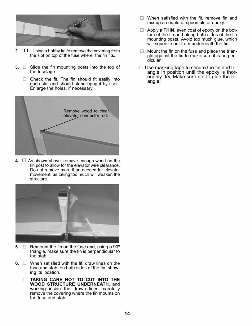
CENTERPOINT
7. Place the stab on the platform with the cen-ter of the stab lined up with the centerpointon the fuse. Measuring from the mark on each wing tip tothe mark on the stab tip, make sure the dis-tance "X" on the right side and left side of theplane are equal.
13
9. When satisfied with the alignment of thestab, temporarily tape securely in place.Turn over the plane and mark the area on thebottom of the stab where it rests on the fuse.Remove the stab from the fuse and, working1/4" inside the drawn lines, carefully removethe covering from the bottom of the stab. BECAREFUL TO AVOID CUTTING THEWOOD
10. Spread epoxy on both the bottom of the staband the stab platform of the fuse.Replace the stab on the platform and, afteragain checking the alignment of the stab tothe wing, allow the epoxy to dry thoroughly.
8. Make sure the stab is level (parallel) with thewing and insert paper strip shims, if neces-sary.
13. As with the installation of the ailerons, inserta straight pin in the center of each jet hinge.Slide the hinges halfway into the elevatorand then slide the entire assembly into thehinge slots in the stabilizer.
Allow the elevator/stab assembly to dry for atleast 10 minutes before flexing the elevator.
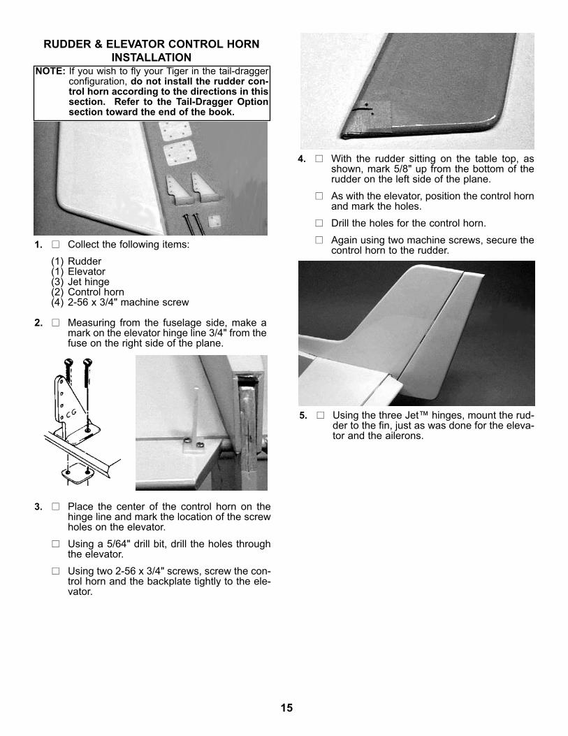
FIN INSTALLATION1. Collect the following items:
(1) Fin
11. Take the elevator joiner wire and trial fitinto each elevator half. Make sure eleva-tors will lie flat and the leading edge isstraight. Adjust the wire if necessary.
12. When satisfied with the fit, mix some 30minute epoxy and work it into the holes inthe elevators and apply in the slots. Insertthe wire and use masking tape to hold inplace until dry. Lay the elevators on a flatsurface to ensure they stay flat and use astraight edge along the leading edge.
Make sure the elevator is centered betweenthe stab tips. If desired, tape the elevator to thestab to keep the pieces together.
14. Keeping the stab and elevator in posi-tion, remove the pins and apply 3 or 4 drops ofZap thin CA to each hinge location.
14
TAKING CARE NOT TO CUT INTO THEWOOD STRUCTURE UNDERNEATH, andworking inside the drawn lines, carefullyremove the covering where the fin mounts onthe fuse and stab.
6. When satisfied with the fit, draw lines on thefuse and stab, on both sides of the fin, show-ing its location.
5. Remount the fin on the fuse and, using a 90ºtriangle, make sure the fin is perpendicular tothe stab.
3. Slide the fin mounting posts into the top ofthe fuselage.Check the fit. The fin should fit easily intoeach slot and should stand upright by itself.Enlarge the holes, if necessary.
2. Using a hobby knife remove the covering fromthe slot on top of the fuse where the fin fits.
4. As shown above, remove enough wood on thefin post to allow for the elevator wire clearance.Do not remove more than needed for elevatormovement, as taking too much will weaken thestructure.
When satisfied with the fit, remove fin andmix up a couple of spoonfuls of epoxy.Apply a THIN, even coat of epoxy on the bot-tom of the fin and along both sides of the finmounting posts. Avoid too much glue, whichwill squeeze out from underneath the fin.Mount the fin on the fuse and place the trian-gle against the fin to make sure it is perpen-dicular.
Use masking tape to secure the fin and tri-angle in position until the epoxy is thor-oughly dry. Make sure not to glue the tri-angle!
Remove wood to clearelevator connector rod.
15
3. Place the center of the control horn on thehinge line and mark the location of the screwholes on the elevator.Using a 5/64" drill bit, drill the holes throughthe elevator. Using two 2-56 x 3/4" screws, screw the con-trol horn and the backplate tightly to the ele-vator.
1. Collect the following items:(1) Rudder(1) Elevator(3) Jet hinge(2) Control horn(4) 2-56 x 3/4" machine screw
2. Measuring from the fuselage side, make amark on the elevator hinge line 3/4" from thefuse on the right side of the plane.
RUDDER & ELEVATOR CONTROL HORNINSTALLATION
NOTE: If you wish to fly your Tiger in the tail-draggerconfiguration, do not install the rudder con-trol horn according to the directions in thissection. Refer to the Tail-Dragger Optionsection toward the end of the book.
4. With the rudder sitting on the table top, asshown, mark 5/8" up from the bottom of therudder on the left side of the plane.As with the elevator, position the control hornand mark the holes.Drill the holes for the control horn. Again using two machine screws, secure thecontrol horn to the rudder.
5. Using the three Jet™ hinges, mount the rud-der to the fin, just as was done for the eleva-tor and the ailerons.
16
OUTFITTING THE FUSELAGEFUEL TANK ASSEMBLY
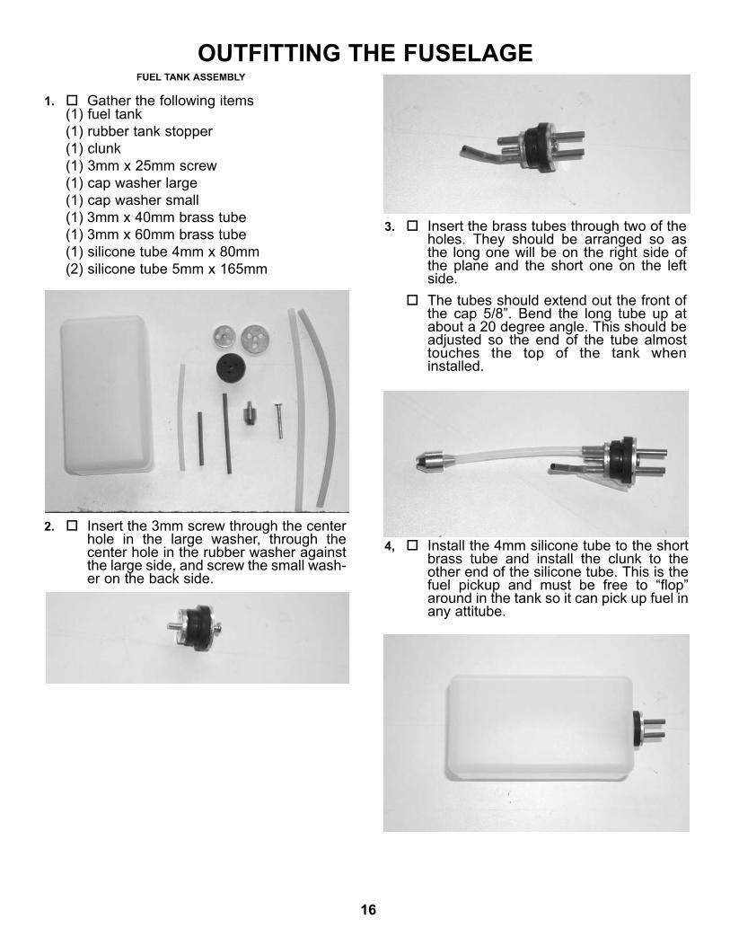
1. Gather the following items(1) fuel tank(1) rubber tank stopper(1) clunk (1) 3mm x 25mm screw(1) cap washer large(1) cap washer small(1) 3mm x 40mm brass tube(1) 3mm x 60mm brass tube(1) silicone tube 4mm x 80mm(2) silicone tube 5mm x 165mm
2. Insert the 3mm screw through the centerhole in the large washer, through thecenter hole in the rubber washer againstthe large side, and screw the small wash-er on the back side.
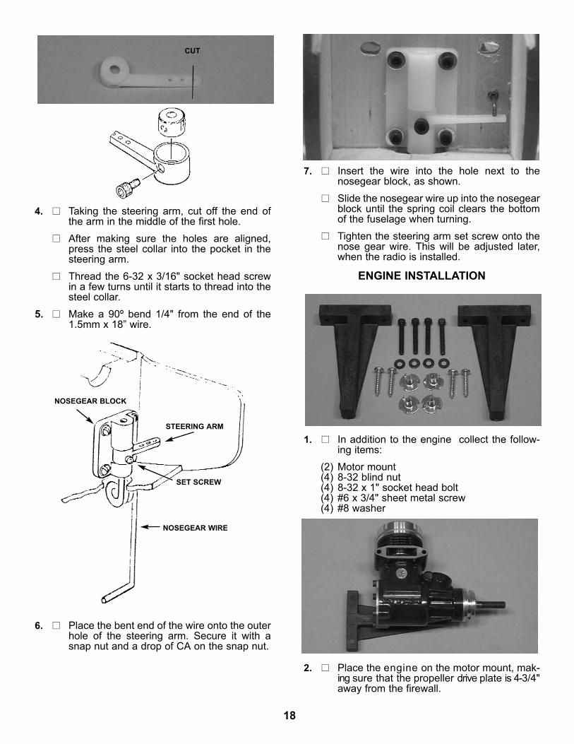
3. Insert the brass tubes through two of theholes. They should be arranged so asthe long one will be on the right side ofthe plane and the short one on the leftside.The tubes should extend out the front ofthe cap 5/8”. Bend the long tube up atabout a 20 degree angle. This should beadjusted so the end of the tube almosttouches the top of the tank wheninstalled.
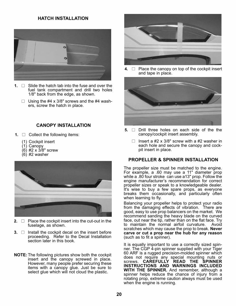
4, Install the 4mm silicone tube to the shortbrass tube and install the clunk to theother end of the silicone tube. This is thefuel pickup and must be free to “flop”around in the tank so it can pick up fuel inany attitube.

17
6. Attach the two pieces of 5mm tubing tothe two tank outlets. They are differentcolors so you can tell which is the ventand which is the fuel pickup after the tankis installed. Make a note of which coloryou attatch to which tube. The shortbrass with the clunk is the fuel pickupand must go to the carbeuator. The longbrass tube is the vent and should go tothe pressure outlet on the muffler.Set tank aside till ready to install.
5. Install the assembly into the tank so thevent tube is turned up to the top of thetank and is positioned on the right side ofthe tank. Tighten the screw to expand therubber cap. Don’t overtighten or youcould split the tank.
3. Place the 4-40 blind nuts, with the teethpointed toward the firewall, on the ends of thescrews. Tighten until the blind nut teeth arefirmly seated into the wood.
2. Referring to the above photo, and using theallen wrench supplied with this kit, screw thenose gear block to the firewall with the 4-40 x1/2" screws and the #4 washers. Screw thebolts part way until the ends are just comingthrough the back side of the firewall.
1. Gather the following items:(4) 4-40 x 1/2" socket head screw(4) #4 washer(4) 4-40 blind nut(1) Nylon nosegear block(1) Nose Gear Wire(1) 5/32" wheel collar(1) Nylon steering arm(1) 6-32 x 3/16" socket head screw(1) 1.5mm x 18” wire
NOSE GEAR INSTALLATION
Note: Thisblock haschanged.Mount usingthe top holesand drill newbottom holes.
18
ENGINE INSTALLATION
1. In addition to the engine collect the follow-ing items:
(2) Motor mount(4) 8-32 blind nut(4) 8-32 x 1" socket head bolt(4) #6 x 3/4" sheet metal screw(4) #8 washer
2. Place the engine on the motor mount, mak-ing sure that the propeller drive plate is 4-3/4"away from the firewall.
4. Taking the steering arm, cut off the end ofthe arm in the middle of the first hole.After making sure the holes are aligned,press the steel collar into the pocket in thesteering arm.Thread the 6-32 x 3/16" socket head screwin a few turns until it starts to thread into thesteel collar.
5. Make a 90º bend 1/4" from the end of the1.5mm x 18” wire.
6. Place the bent end of the wire onto the outerhole of the steering arm. Secure it with asnap nut and a drop of CA on the snap nut.
7. Insert the wire into the hole next to thenosegear block, as shown.Slide the nosegear wire up into the nosegearblock until the spring coil clears the bottomof the fuselage when turning.Tighten the steering arm set screw onto thenose gear wire. This will be adjusted later,when the radio is installed.
NOSEGEAR BLOCK
CUT
STEERING ARM
SET SCREW
NOSEGEAR WIRE

19
FUEL TANK INSTALLATION
3. With the blind nut seated backward (teethpointing to rear of fuse), bolt the secondmotor mount to the firewall opposite the sideof the mount that is screwed to the engine.
Again with the blind nut teeth facing the rear,bolt the motor mount and engine to the fire-wall.
4. Slide the motor mounts around until they arecentered on the firewall and are tight to theengine.Mark the screw locations for the loose motormount and drill pilot holes for mounting.Use the remaining #6 x 3/4” screws to com-plete the mounting of the engine to themount.
1. Collect the following items:(1) 1/2 x 8 x 12" piece of foam rubber( not
included).(1) Assembled fuel tank
2. Cut two 3-1/2 x 1-1/2" pieces from the pieceof foam rubber.
From the leftover piece, cut a 2" wide strip.
Drill a 1/8" pilot hole for two #6 x 3/4" sheetmetal screws.Screw the engine to the motor mount.
5. Unscrewing one motor mount screw at atime, turn the blind nut around, so that theteeth will stick into the firewall, and retightenthe screw until the blind nuts are firmly seat-ed.
3. Put one of the 1-1/2" wide foam pieces in thebottom of the fuel tank compartment in thefuselage.
4. Taking note of which tube is the vent andwhich is the fuel pickup,route the fuel tubinginto the engine compartment, resting on thehalf-circle cut-out in the former.
5. Place the fuel tank down inside the tank com-partment and place the second 1-1/2" pieceof foam on top of the tank.
6. Cut the fuel tubing to reach the engine car-buretor and muffler and attach these cutends to the carb and muffler.
20
HATCH INSTALLATION
CANOPY INSTALLATION
PROPELLER & SPINNER INSTALLATION
1. Slide the hatch tab into the fuse and over thefuel tank compartment and drill two holes1/8" back from the edge, as shown.Using the #4 x 3/8" screws and the #4 wash-ers, screw the hatch in place.
1. Collect the following items:(1) Cockpit insert(1) Canopy(6) #2 x 3/8" screw(6) #2 washer
2. Place the cockpit insert into the cut-out in thefuselage, as shown.
3. Install the cockpit decal on the insert beforeproceeding. Refer to the Decal Installationsection later in this book.
NOTE: The following pictures show both the cockpitinsert and the canopy screwed in place.However, many people prefer securing theseitems with a canopy glue. Just be sure toselect glue which will not cloud the plastic.
4. Place the canopy on top of the cockpit insertand tape in place.
5. Drill three holes on each side of the thecanopy/cockpit insert assembly.Insert a #2 x 3/8" screw with a #2 washer ineach hole and secure the canopy and cock-pit insert in place.
The propeller size must be matched to the engine.For example, a .60 may use a 11" diameter propwhile a .80 four stroke can use a13" prop. Follow theengine manufacturer’s recommendation for correctpropeller sizes or speak to a knowledgeable dealer.It's wise to buy a few spare props, as everyonebreaks them occasionally, and particularly oftenwhen learning to fly.Balancing your propeller helps to protect your radiofrom the damaging effects of vibration. There aregood, easy to use prop balancers on the market. Werecommend sanding the heavy blade on the curvedface, out near the tip, rather than on the flat face. Tryto maintain the normal airfoil curvature. Avoidscratches which may cause the prop to break. Nevercarve or cut a prop near the hub for any reason(such as to fit a spinner).
It is equally important to use a correctly sized spin-ner. The CGP 4-pin spinner supplied with your Tiger60 ARF is a rugged precision-molded spinner whichdoes not require any special mounting nuts orscrews. CAREFULLY READ THE SPINNERINSTRUCTIONS AND WARNINGS INCLUDEDWITH THE SPINNER. And remember, although aspinner helps reduce the chance of injury from arotating prop, extreme caution always must be usedwhen the engine is running.
21
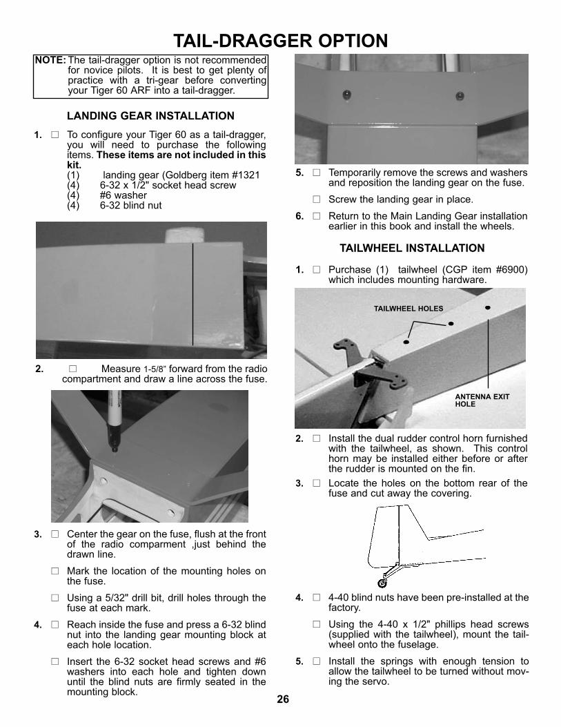
3. Locate the exit hole on the rear fuselage sideand remove the covering from over the hole.
SERVO & PUSHROD INSTALLATION
1. Collect the following items:(2) 5/16” x 19” dowels(1) 1.5mm x 18” throttle rod(2) Pushrod connector body(2) Snap nut(2) Snap-r-keeper(3) Radio servos with mounting hardware(2) Snap link(2) 1/4” silicone Snap link keepers(4) 1/2” x 2” heat shrink tubing(2) 2mm x 8” Pushrod ends unthreaded both ends.(2) 2mm x 12” Pushrod ends threaded one end (1) 2mm x 18” Pushrod threaded one end
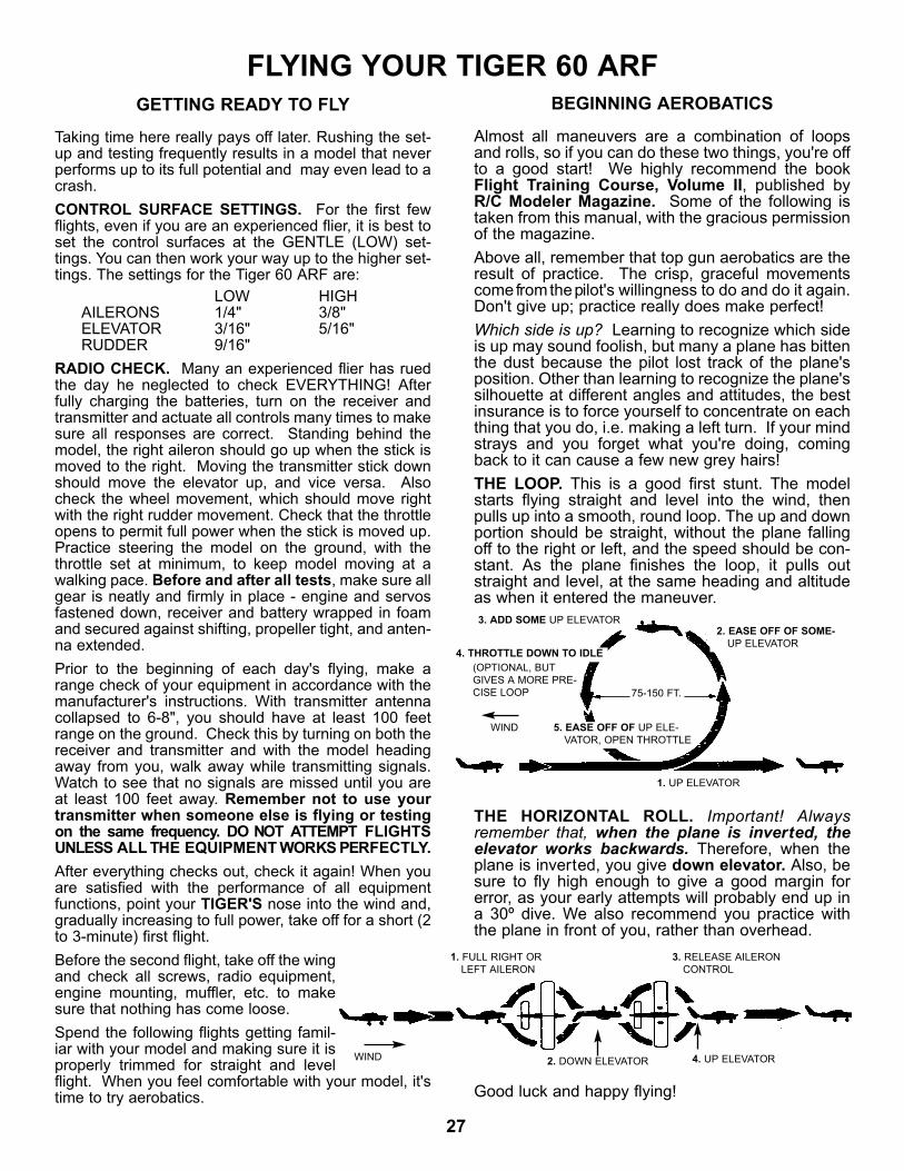
2. Remove all but one of the servo arms, so thatthey look like the above drawing. You will needtwo of these.
RADIO INSTALLATION
EXIT HOLE ON SIDE OF FUSE
Remove all of the graycolored areas
4. Locate the two 5/16” dowels and meas-ure in 1-1/4” from each end and drill a5/64” hole. Using your hobby knife orMoto tool, cut a slot from the hole to theend of the dowel that the 2mm wire will fitinto. Locate the two 2mm x 12” rods and measure 10-1/2” from the threaded end and make a 90 degree bend. Cut the bent end off at 3/8”. One will be the elevator and one will be the rudderpushrod.
5. Insert the bent end of the pushrod intothe dowel and press into the slot. ApplyCA glue then slide the shrink tubing overthe end allowing it to overhang the end ofthe dowel 1/8”. Shrink tight using a heatgun. If you don’t have a heat gun you canheat it on your kitchen range. Install oneon each dowel.Locate the two 2mm x 8” unthreadedrods and bend a 90 degree angle on oneend 3/8” long. Install these on the otherend of the two dowels in the same man-ner.
22
Insert the wire though the outer servo armhole and install a snap-r-keeper on the wire.
9. Insert the other pushrod into the fuselageand exit through the guide on the left side.Again remove the covering over the exit hole. As with the elevator servo pushrod, thread asnap link onto the end of the wire and thenattach the snap link to the rudder controlhorn. Be sure to slide the silicone rubberkeeper onto the snap linkWith the rudder in neutral position, tape therudder to the fin.
8. Place the servo arm onto the elevator servo,so that the arm is perpendicular to the cen-terline of the servo and the elevator pushrodwire passes over the top of the servo arm.Mark where the wire crosses over the outerhole in the servo arm.Using a long-nose pliers, make a 90º bendupward at the mark.
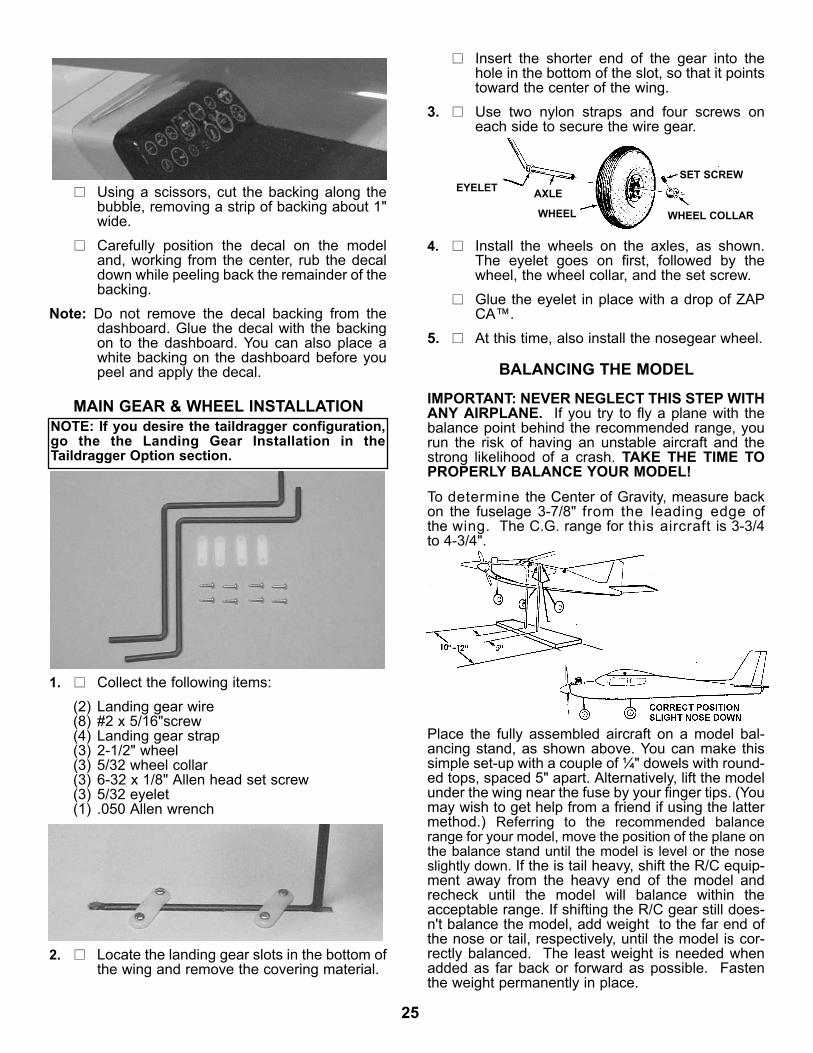
7. Take the two pushrods you made and bendthe end with the threaded rod out at a 10degree angle. Avoid sharp bends in thepushrod, we only want it to turn our slightly.Route the pushrod into the fuselage and outthe exit on the right side of the plane.
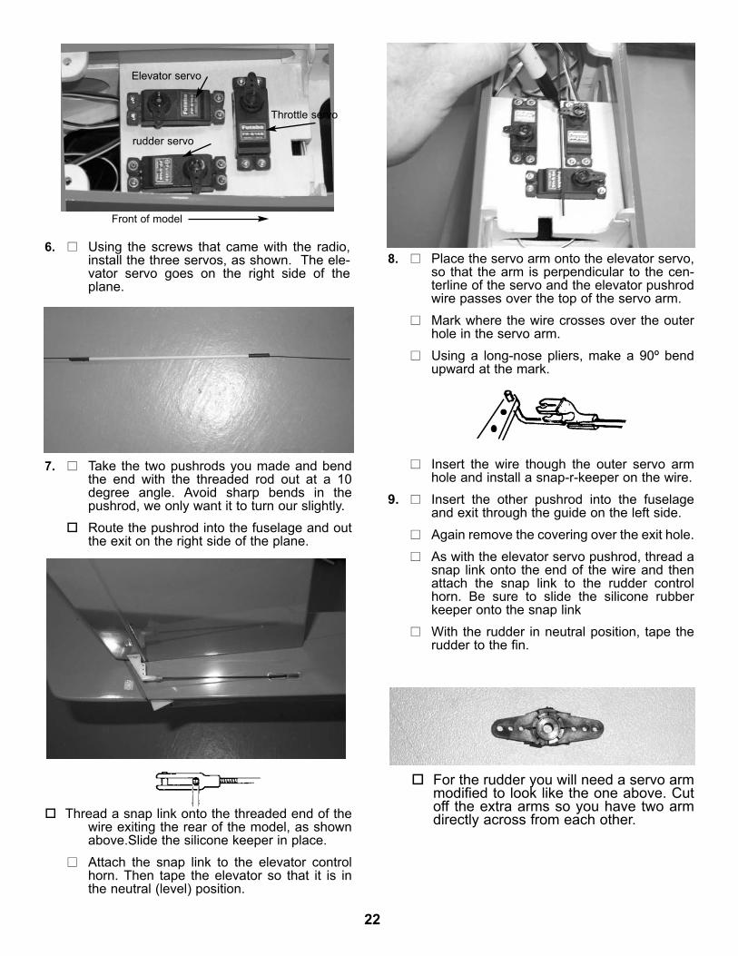
6. Using the screws that came with the radio,install the three servos, as shown. The ele-vator servo goes on the right side of theplane.
Front of model
Throttle servo
Elevator servo
rudder servo
Thread a snap link onto the threaded end of thewire exiting the rear of the model, as shownabove.Slide the silicone keeper in place.Attach the snap link to the elevator controlhorn. Then tape the elevator so that it is inthe neutral (level) position.
For the rudder you will need a servo armmodified to look like the one above. Cutoff the extra arms so you have two armdirectly across from each other.

23
RADIO SWITCH INSTALLATION
1. Collect the following items:(1) Radio switch(1) Switch mount(1) Switch mount bolt(1) Switch cap(1) Switch push-pull(2) #2 washer
10. With the servo arm NOT ATTACHED to theservo, mount a pushrod connector to themiddle hole on the servo arm.
Insert the nosegear pushrod into the pushrodconnector on the rudder servo arm. Place the servo arm onto the rudder servo,with the rudder pushrod passing over the topof the arm.
11. Making sure the arm is perpendicular to thecenterline of the servo, mark where the wirecrosses over the outer hole in the servo arm.Make a 90º upward bend at the mark in thewire.
12. Place a snap-r-keeper onto the top of therudder wire and push it into place.
13. Remount the servo arm on the servo, againpositioned so it is perpendicular to the servocenterline.
Making sure that the rudder is in the neutralposition and the nose gear is pointing straightahead, tighten the setscrew on top of thepushrod connector.
14. On the 18" wire threaded on one end, installa snap link.and silicone keeper.
15. Insert the wire into the tube that is in front ofthe firewall and right behind the engine throt-tle arm. Slide the wire into the tube until the snap linkcan be placed onto the engine throttle arm.
Remove the servo arm and insert the rudderpushrod into the outer hole in servo armwhile keeping the nosegear pushrod in thepushrod connector.
PUSHROD CONNECTOR
SNAP NUT
16. Install a pushrod connector on the third servoarm. Insert the throttle wire into the pushrodconnector and place the arm on the throttleservo.The throttle servo movement will be adjustedafter the receiver and battery pack areinstalled.
DuBro switch mount Part # 203 not included in kit.

24
RECEIVER AND BATTERY INSTALLATION
2. If your radio has a switch cover, remove boththe screw and the cover from the top of theswitch.Using the screw just removed, as well as the#2 washer, assemble the switch mount asshown.
3. The switch mount has one slotted hole onone side and two holes on the other side.Mount the switch so that it will move backand forth. It will be possible to feel and hearthe click.Locate the switch on the left side of the fuse,about 3-3/16" up from the bottom of the fuseand 9-5/16" from the nose of the fuse.
4. Drill a 1/4" hole and insert the switch mountbolt through the hole.Screw it into the switch mount. Then, insertthe push-pull and screw it into the switchcap.
1. Insert the Y-harness into the the aileronplug in the receiver and then wrap both thereceiver and the battery in the 1/2" foam.
2. Place the receiver just behind the radioswitch and the battery in front of the servos.Plug in all of the servos, keeping both theaileron and the charge cord accessible.Glue the two wood pieces (from scrap) to thefuse sides, as shown, to keep the receiverand battery from shifting.
DECAL APPLICATION
1. Using glass cleaner and a soft cloth, cleanthe model surface thoroughly before apply-ing decals.
2. Cut the decal sheets apart in sections, asneeded.Fold the decal in half, front to rear. Open atthe fold and place the decal on a flat surface.The protective backing will bubble away fromthe decal at the fold.
Switch can be mounted in servo tray if DuBro switch mount is not used.
25
MAIN GEAR & WHEEL INSTALLATION
BALANCING THE MODEL
Using a scissors, cut the backing along thebubble, removing a strip of backing about 1"wide.Carefully position the decal on the modeland, working from the center, rub the decaldown while peeling back the remainder of thebacking.
Note: Do not remove the decal backing from thedashboard. Glue the decal with the backingon to the dashboard. You can also place awhite backing on the dashboard before youpeel and apply the decal.
1. Collect the following items:(2) Landing gear wire(8) #2 x 5/16"screw(4) Landing gear strap(3) 2-1/2" wheel(3) 5/32 wheel collar(3) 6-32 x 1/8" Allen head set screw(3) 5/32 eyelet(1) .050 Allen wrench
4. Install the wheels on the axles, as shown.The eyelet goes on first, followed by thewheel, the wheel collar, and the set screw.Glue the eyelet in place with a drop of ZAPCA™.
5. At this time, also install the nosegear wheel.
2. Locate the landing gear slots in the bottom ofthe wing and remove the covering material.
NOTE: If you desire the taildragger configuration,go the the Landing Gear Installation in theTaildragger Option section.
EYELET AXLE
WHEEL
SET SCREW
WHEEL COLLAR
Insert the shorter end of the gear into thehole in the bottom of the slot, so that it pointstoward the center of the wing.
3. Use two nylon straps and four screws oneach side to secure the wire gear.
IMPORTANT: NEVER NEGLECT THIS STEP WITHANY AIRPLANE. If you try to fly a plane with thebalance point behind the recommended range, yourun the risk of having an unstable aircraft and thestrong likelihood of a crash. TAKE THE TIME TOPROPERLY BALANCE YOUR MODEL!To determine the Center of Gravity, measure backon the fuselage 3-7/8" from the leading edge ofthe wing. The C.G. range for this aircraft is 3-3/4to 4-3/4".
Place the fully assembled aircraft on a model bal-ancing stand, as shown above. You can make thissimple set-up with a couple of ¼" dowels with round-ed tops, spaced 5" apart. Alternatively, lift the modelunder the wing near the fuse by your finger tips. (Youmay wish to get help from a friend if using the lattermethod.) Referring to the recommended balancerange for your model, move the position of the plane onthe balance stand until the model is level or the noseslightly down. If the is tail heavy, shift the R/C equip-ment away from the heavy end of the model andrecheck until the model will balance within theacceptable range. If shifting the R/C gear still does-n't balance the model, add weight to the far end ofthe nose or tail, respectively, until the model is cor-rectly balanced. The least weight is needed whenadded as far back or forward as possible. Fastenthe weight permanently in place.
26
LANDING GEAR INSTALLATION
TAILWHEEL INSTALLATION
1. To configure your Tiger 60 as a tail-dragger,you will need to purchase the followingitems. These items are not included in thiskit.(1) landing gear (Goldberg item #1321(4) 6-32 x 1/2" socket head screw(4) #6 washer(4) 6-32 blind nut
2. Measure 1-5/8” forward from the radiocompartment and draw a line across the fuse.
3. Center the gear on the fuse, flush at the frontof the radio comparment ,just behind thedrawn line.Mark the location of the mounting holes onthe fuse.Using a 5/32" drill bit, drill holes through thefuse at each mark.
4. Reach inside the fuse and press a 6-32 blindnut into the landing gear mounting block ateach hole location.Insert the 6-32 socket head screws and #6washers into each hole and tighten downuntil the blind nuts are firmly seated in themounting block.
5. Temporarily remove the screws and washersand reposition the landing gear on the fuse.Screw the landing gear in place.
6. Return to the Main Landing Gear installationearlier in this book and install the wheels.
TAIL-DRAGGER OPTION
1. Purchase (1) tailwheel (CGP item #6900)which includes mounting hardware.
2. Install the dual rudder control horn furnishedwith the tailwheel, as shown. This controlhorn may be installed either before or afterthe rudder is mounted on the fin.
3. Locate the holes on the bottom rear of thefuse and cut away the covering.
4. 4-40 blind nuts have been pre-installed at thefactory.Using the 4-40 x 1/2" phillips head screws(supplied with the tailwheel), mount the tail-wheel onto the fuselage.
5. Install the springs with enough tension toallow the tailwheel to be turned without mov-ing the servo.
TAILWHEEL HOLES
ANTENNA EXITHOLE
NOTE: The tail-dragger option is not recommendedfor novice pilots. It is best to get plenty ofpractice with a tri-gear before convertingyour Tiger 60 ARF into a tail-dragger.
27
FLYING YOUR TIGER 60 ARFGETTING READY TO FLY BEGINNING AEROBATICS
Taking time here really pays off later. Rushing the set-up and testing frequently results in a model that neverperforms up to its full potential and may even lead to acrash.CONTROL SURFACE SETTINGS. For the first fewflights, even if you are an experienced flier, it is best toset the control surfaces at the GENTLE (LOW) set-tings. You can then work your way up to the higher set-tings. The settings for the Tiger 60 ARF are:
LOW HIGHAILERONS 1/4" 3/8"ELEVATOR 3/16" 5/16"RUDDER 9/16"
RADIO CHECK. Many an experienced flier has ruedthe day he neglected to check EVERYTHING! Afterfully charging the batteries, turn on the receiver andtransmitter and actuate all controls many times to makesure all responses are correct. Standing behind themodel, the right aileron should go up when the stick ismoved to the right. Moving the transmitter stick downshould move the elevator up, and vice versa. Alsocheck the wheel movement, which should move rightwith the right rudder movement. Check that the throttleopens to permit full power when the stick is moved up.Practice steering the model on the ground, with thethrottle set at minimum, to keep model moving at awalking pace. Before and after all tests, make sure allgear is neatly and firmly in place - engine and servosfastened down, receiver and battery wrapped in foamand secured against shifting, propeller tight, and anten-na extended.Prior to the beginning of each day's flying, make arange check of your equipment in accordance with themanufacturer's instructions. With transmitter antennacollapsed to 6-8", you should have at least 100 feetrange on the ground. Check this by turning on both thereceiver and transmitter and with the model headingaway from you, walk away while transmitting signals.Watch to see that no signals are missed until you areat least 100 feet away. Remember not to use yourtransmitter when someone else is flying or testingon the same frequency. DO NOT ATTEMPT FLIGHTSUNLESS ALL THE EQUIPMENT WORKS PERFECTLY.After everything checks out, check it again! When youare satisfied with the performance of all equipmentfunctions, point your TIGER'S nose into the wind and,gradually increasing to full power, take off for a short (2to 3-minute) first flight.Before the second flight, take off the wingand check all screws, radio equipment,engine mounting, muffler, etc. to makesure that nothing has come loose.Spend the following flights getting famil-iar with your model and making sure it isproperly trimmed for straight and levelflight. When you feel comfortable with your model, it'stime to try aerobatics.
Almost all maneuvers are a combination of loopsand rolls, so if you can do these two things, you're offto a good start! We highly recommend the bookFlight Training Course, Volume II, published byR/C Modeler Magazine. Some of the following istaken from this manual, with the gracious permissionof the magazine.Above all, remember that top gun aerobatics are theresult of practice. The crisp, graceful movementscome from the pilot's willingness to do and do it again.Don't give up; practice really does make perfect!Which side is up? Learning to recognize which sideis up may sound foolish, but many a plane has bittenthe dust because the pilot lost track of the plane'sposition. Other than learning to recognize the plane'ssilhouette at different angles and attitudes, the bestinsurance is to force yourself to concentrate on eachthing that you do, i.e. making a left turn. If your mindstrays and you forget what you're doing, comingback to it can cause a few new grey hairs!THE LOOP. This is a good first stunt. The modelstarts flying straight and level into the wind, thenpulls up into a smooth, round loop. The up and downportion should be straight, without the plane fallingoff to the right or left, and the speed should be con-stant. As the plane finishes the loop, it pulls outstraight and level, at the same heading and altitudeas when it entered the maneuver.
THE HORIZONTAL ROLL. Important! Alwaysremember that, when the plane is inverted, theelevator works backwards. Therefore, when theplane is inverted, you give down elevator. Also, besure to fly high enough to give a good margin forerror, as your early attempts will probably end up ina 30º dive. We also recommend you practice withthe plane in front of you, rather than overhead.
Good luck and happy flying!
WIND
(OPTIONAL, BUTGIVES A MORE PRE-CISE LOOP
1. UP ELEVATOR
2. EASE OFF OF SOME-UP ELEVATOR
5. EASE OFF OF UP ELE-VATOR, OPEN THROTTLE
3. ADD SOME UP ELEVATOR
4. THROTTLE DOWN TO IDLE
75-150 FT.
2. DOWN ELEVATOR 4. UP ELEVATOR
3. RELEASE AILERONCONTROL
1. FULL RIGHT ORLEFT AILERON
WIND