This document is not an Standard; it is under...
27
This document is not an API Standard; it is under consideration within an API technical committee but has not received all approvals required to become an API Standard. It shall not be reproduced or circulated or quoted, in whole or in part, outside of API committee activities except with the approval of the Chairman of the committee having jurisdiction and staff of the API Standards Dept. Copyright API. All rights reserved. Manual of Petroleum Measurement Standards Chapter 6—Metering Assemblies Section 3A —Pipeline and Marine Loading/Unloading Measurement Systems Draft Edition January 2018
-
Upload
nguyenkhue -
Category
Documents
-
view
216 -
download
0
Transcript of This document is not an Standard; it is under...

This document is not an API Standard; it is under consideration within an API technical committee but has not received all approvals required to become an API Standard. It shall not be reproduced or circulated or quoted, in whole or in part, outside of API committee activities except with the approval of the Chairman of the committee having jurisdiction and staff of the API Standards Dept. Copyright API. All rights reserved.
Manual of Petroleum Measurement Standards Chapter 6—Metering Assemblies
Section 3A —Pipeline and Marine
Loading/Unloading Measurement Systems
Draft Edition January 2018

This document is not an API Standard; it is under consideration within an API technical committee but has not received all approvals required to become an API Standard. It shall not be reproduced or circulated or quoted, in whole or in part, outside of API committee activities except with the approval of the Chairman of the committee having jurisdiction and staff of the API Standards Dept. Copyright API. All rights reserved.
Introduction
This standard serves as a guide in the selection, installation and operation of pipeline and marine loading and unloading, FPSO (Floating Production, Storage, and Offloading) and FSO (Floating Storage and Offloading) metering systems. This standard does not endorse or advocate the preferential use of any specific type of metering system or meter.
In general, metering system installations must meet certain fundamental requirements, including those that ensure proper meter type, size, installation, and adequate protective and readout devices. Descriptions of metering system components are included either in this standard or other API MPMS Chapters.

This document is not an API Standard; it is under consideration within an API technical committee but has not received all approvals required to become an API Standard. It shall not be reproduced or circulated or quoted, in whole or in part, outside of API committee activities except with the approval of the Chairman of the committee having jurisdiction and staff of the API Standards Dept. Copyright API. All rights reserved.
1 SCOPE
This standard is part of a set of documents which detail the minimum requirements for metering systems in single phase liquid applications. This standard (Section 6.3A) details the specific requirements for the design, selection, and operation of pipeline, marine loading and unloading, FPSO, and FSO metering systems.
LACT measurement, multiphase fluids, asphalts, wellhead and subsea measurements are not covered by this standard.
2 APPLICATION
Sections of Chapter 6 describe metering system design. Section 6.1A describes the general considerations applicable to all metering systems and shall be consulted together with this standard, Ch. 6.3A, when designing systems. When aspects are covered under the scope of other chapters of the API Manual of Petroleum Measurement Standards, and to avoid replication and conflict, they are not covered by this standard. In these cases, this standard provides limited information and refers the user to those chapters.
3 NORMATIVE REFERENCES
The following referenced documents are indispensable for the application of this document. For dated references, only the edition cited applies. For undated references, the latest edition of the referenced document (including any amendments) applies.
API MPMS Chapter 6.1A, General Considerations GPA 2177, Analysis of Natural Gas Liquid Mixtures Containing Nitrogen and Carbon Dioxide by Gas Chromatography
4 TERMS, DEFINITIONS AND SYMBOLS
4.1 Terms and Definitions
For the purposes of this document, the following terms and definitions apply. Terms of more general use may be found in the API MPMS Chapter 1 Online Terms and Definitions Database.
4.1.1 floating production storage and offloading vessel A floating vessel design to produce and process hydrocarbons from subsea sources or the collection of produced oil from nearby platforms, storage of oil and transfer of the hydrocarbons to other vessels or pipelines for transport.
4.1.2 floating storage and offloading vessel A floating vessel design to store produced hydrocarbons from nearby platforms or FPSO's, and transfer of the hydrocarbons to other vessels or pipelines for transport.
4.1.3 marine loading metering system A metering system designed to measure hydrocarbons transferred from a shore terminal or refinery to a vessel (ship or barge).

This document is not an API Standard; it is under consideration within an API technical committee but has not received all approvals required to become an API Standard. It shall not be reproduced or circulated or quoted, in whole or in part, outside of API committee activities except with the approval of the Chairman of the committee having jurisdiction and staff of the API Standards Dept. Copyright API. All rights reserved.
4.1.4 marine metering system A metering system that is designed to measure hydrocarbon between a vessel (ship or barge) and a shore terminal or refinery.
4.1.5 marine unloading metering system A metering system designed to measure hydrocarbons transferred from a vessel (ship or barge) to a shore terminal or refinery.
4.1.6 pipeline metering system A metering system that is used to measure hydrocarbons transferred between a pipeline, and another pipeline, terminal or refinery.
4.1.7 turndown ratio The ratio of the maximum capacity of a device (e.g., meter or metering system, transmitter) to the minimum capacity of the device. Normally, the turndown ratio for a meter is determined by dividing the maximum normal linear capacity by the minimum normal linear capacities. The turndown ratio for a transmitter is determined by dividing the Upper Range Value (URV) by the Lower Range Value (LRV) (if non-zero).
4.1.8 viscous hydrocarbon Any liquid hydrocarbon that resists flow because of high shear or tensile stress and therefore may require special treatment or equipment in its handling or storage.
4.2 Acronyms, Abbreviations, and Symbols
DP – differential pressure
DB&B – double block and bleed
FPSO – floating production storage and offloading
FSO – floating storage and offloading
PD – positive displacement
PLC – programmable logic controller
LPG – liquefied petroleum gas
NGL – natural gas liquid
5 METERING SYSTEM OVERVIEW
5.1 Pipeline Metering Systems
A metering system is a combination of primary, secondary, tertiary measurement components, along with piping and other equipment and instrumentation necessary to determine the measurement ticket. How a ticket (also called quantity transaction record (QTR), batch ticket, or measurement ticket) is calculated is dependent upon the type of meter used (volumetric or mass) and the quantity units.
All metering systems in this section have the following general characteristics:
This document is not an API Standard; it is under consideration within an API technical committee but has not received all approvals required to become an API Standard. It shall not be reproduced or circulated or quoted, in whole or in part, outside of API committee activities except with the approval of the Chairman of the committee having jurisdiction and staff of the API Standards Dept. Copyright API. All rights reserved.
Provide for performance verification of all components Provide a means of proving Provide a means to determine or account for quality Provide accessibility of the equipment for maintenance
5.2 Pipeline Metering Systems
A pipeline metering system is used for custody transfer measurement between a pipeline and connecting pipeline, terminal, or refinery, and has the following characteristics:
Typically, do not require large volume air eliminators. Small volume air eliminators should be considered for applications where meters are installed vertically. A method of verifying the integrity of the high point bleeds shall be provided.
Typically, have reduced turndown considerations.
5.3 Marine Metering Systems
5.3.1 General
A marine metering system is used for custody transfer measurement between a marine vessel and shore facility. Metering offers several advantages over tank gauging, including minimum vessel turnaround time, increased reliability and accuracy, improved uncertainty, traceable field standards (provers), automated reporting, and safety.
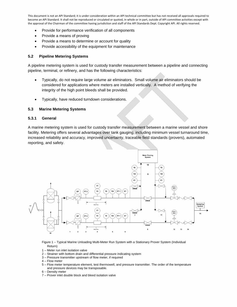
Figure 1 – Typical Marine Unloading Multi-Meter Run System with a Stationary Prover System (Individual Return)
1 – Meter run inlet isolation valve 2 – Strainer with bottom drain and differential pressure indicating system 3 – Pressure transmitter upstream of flow meter, if required 4 – Flow meter 5 – Flow meter temperature element, test thermowell, and pressure transmitter. The order of the temperature
and pressure devices may be transposable. 6 – Density meter 7 – Prover inlet double block and bleed isolation valve

This document is not an API Standard; it is under consideration within an API technical committee but has not received all approvals required to become an API Standard. It shall not be reproduced or circulated or quoted, in whole or in part, outside of API committee activities except with the approval of the Chairman of the committee having jurisdiction and staff of the API Standards Dept. Copyright API. All rights reserved.
8 – Prover main-line double block and bleed block valve 9 – Prover temperature element, test thermowell, and pressure transmitter. The order of the temperature and
pressure devices may be transposable. Devices may be installed on both the prover inlet and return or on either the prover inlet or return.
10 – Meter proving system 11 – Prover return isolation valve 12 – Flow control / back-pressure valve 13 – Check valve, if required 14 – Meter run outlet isolation valve 15 – Sampling system 16 – Air eliminator 17 – Vessel unloading system Note: This simplified figure indicates components for a typical marine measurement system, but is not intended
to indicate preferred locations. All sections of the system that may be isolated should have provisions for pressure relief (preferably not to be installed between the meter and prover).
5.3.2 Marine Loading
Marine loading is the movement of liquid hydrocarbons from shore to vessel. Figure 1 shows a typical marine unloading measurement system; however, a marine loading measurement system is typically very similar with the exception that the air eliminator may not be required and the vessel loading system is downstream of the marine loading measurement system. Some of the issues that need to be considered include the following:
Air elimination, if required Line verification
o Line displacement o Compatibility with current cargo o Quantity of line fill
Typically have larger turndowns Minimization of vessel turnaround time
5.3.3 Marine Unloading
Marine unloading is the movement of liquid hydrocarbon from vessel to shore. Figure 1 shows a typical marine unloading metering system. Some of the issues that need to be considered include the following:
Air elimination is required Line verification
o Line displacement o Compatibility with current cargo o Quantity of line fill
Typically have larger turndowns Minimization of vessel turnaround time
5.4 FPSO and FSO Metering Systems
FPSO and FSO metering system is used for custody transfer measurement for metering systems installed on FPSOs and FSOs and has the following characteristics:
Typically requires a smaller footprint and weight is a large consideration. Equipment is typically mounted on self-contained skid

This document is not an API Standard; it is under consideration within an API technical committee but has not received all approvals required to become an API Standard. It shall not be reproduced or circulated or quoted, in whole or in part, outside of API committee activities except with the approval of the Chairman of the committee having jurisdiction and staff of the API Standards Dept. Copyright API. All rights reserved.
6 SYSTEM DESIGN AND INSTALLATION CONSIDERATIONS
6.1 Define Design Criteria
Metering systems can have various configurations, depending on flow rate, intermittent or continuous operation, maintenance requirements, redundancy requirements, economics, proving requirements, or prover design.
Metering systems are designed based on the fluid properties (density, viscosity, vapor pressure), operating parameters (flow range, pressure, temperature, batch (parcel) sizes, etc.) and other requirements (available utilities, bi-directional vs. unidirectional operation, etc.) associated with the application. Meter types are chosen based on the meter’s ability to measure the fluid accurately over the given systems flow range. Meters are sized depending on the overall system flow rate and meter run configuration (single or multiple meters). All system components (meter, prover, sampling system, etc.) should be designed to be able to meet minimum and maximum flow rates.
On all metering system configurations, lines to and from the prover should be sized so that aligning the meter to the prover minimizes flow rate change. Additionally, the design should allow for maintaining the operating flow rate while meter is being proved. This can be done by using control valves to balance flow.
To ensure accurate meter factors, metering systems shall be designed so that all the liquid that passes through the meter passes through the prover and no additional liquid is introduced between the meter and prover during meter proving.
If pressure relief is needed to protect the meter run, it should not be installed between the meter and the prover. While it is not recommended, if a pressure relief needs to be installed between the meter and the prover, a means must be in place to assure that the pressure relief is not leaking by during proving operations as this will greatly affect meter factors attained from the proving. (See Chapter 6.1A for additional information.)
The number of vents, drains and thermal relief valves on the piping between a meter(s) and prover (connections), and between a meter(s) and the point of custody transfer shall be kept to a minimum. If installed in either of these locations, each vent, drain or thermal relief shall be provided with a means to permit examination for, or prevention of, leakage. See Chapter 6.1A for additional information.
In Coriolis and ultrasonic meter applications, provisions for meter isolation should be considered in the design to allow for periodic meter downtime to permit verification, and if required, adjustment of the zero of each meter.
6.2 Metering Technology Selection
Without precluding new technologies that may become available in the future, the following four technologies are considered acceptable for use in custody transfer pipeline, marine, FPSO and FSO metering systems:
Positive displacement meter Turbine meter Coriolis force mass meter Ultrasonic meter

This document is not an API Standard; it is under consideration within an API technical committee but has not received all approvals required to become an API Standard. It shall not be reproduced or circulated or quoted, in whole or in part, outside of API committee activities except with the approval of the Chairman of the committee having jurisdiction and staff of the API Standards Dept. Copyright API. All rights reserved.
Reference API MPMS Chapter 5.1 for guidelines for selecting meter types. Also reference meter manufacturers’ and company measurement policy recommendations on meter flow ranges, pressure drops, and process fluids.
The use of any of the above technologies may be considered for applications within the scope of this section. There are a few non-typical flow parameter considerations that may influence meter technology selection. These include:
High viscosity o The use of PD meters with high viscosity clearances should be considered o The use of conventional turbine meters without appropriate viscosity correction in
this service is not recommended o The increased pressure drop associated with a Coriolis meter should be
considered in meter selection High abrasiveness/contamination/paraffinic
o Meter technology selection should consider the impact of erosion on the metering elements. The decision should consider the type of contamination and degree of abrasiveness and its effect on the meter’s metallurgy.
o Applications with high paraffin content may lead to a build-up on the meter internals and lead to a reduced meter performance.
High temperatures o May affect associated electronics that are close-coupled. Remote mounting of
electronics should be considered.
6.3 Meter System Configuration
6.3.1 General
Typically, a metering system design consists of the following elements:
Inlet/Outlet isolation valve Strainer Pressure, temperature, and density instrumentation Other liquid quality measurement devices including sampling systems Meter with applicable flow conditioning upstream and downstream piping Prover main-line block valve Prover inlet and return valve Stationary or portable prover Flow/back pressure Control Valve
See Sections 8 and 9 for a more thorough discussion of each of the above.
6.3.2 Single Meter Run System
The single meter system design should be considered when the flow rate is in a consistent range within the linear portion of the meter and can meet the turndown ratio of the meter, prover, sampling system, or other applicable components.
If a single meter is provided and maintenance is required (e.g., for out-of-tolerance meter factor, mechanical or electronic issue, etc.), either the custody transfer must be halted or flow must be diverted

This document is not an API Standard; it is under consideration within an API technical committee but has not received all approvals required to become an API Standard. It shall not be reproduced or circulated or quoted, in whole or in part, outside of API committee activities except with the approval of the Chairman of the committee having jurisdiction and staff of the API Standards Dept. Copyright API. All rights reserved.
through a bypass. Installation and use of a bypass should be undertaken only with agreement by all parties involved with the custody transfer, including any government regulators. If a bypass is to be provided, it shall incorporate a double block-and-bleed valve or other means (e.g., spectacle blind) to assure that flow is not bypassing the meter when the meter is in operation.
Figure 2 – Typical Single Meter Run System with a Portable Prover 1 – Meter run inlet isolation valve 2 – Strainer with bottom drain and differential pressure indicating system 3 – Pressure transmitter upstream of flow meter, if required 4 – Flow meter 5 – Flow meter temperature element, test thermowell, and pressure transmitter. The order of the temperature
and pressure devices may be transposable. 6 – Density meter 7 – Prover main-line double block and bleed block valve 8 – Prover inlet and return isolation valve 9 – Flow control / back-pressure valve 10 – Check valve, if required 11 – Sampling system 12 – Meter run outlet isolation valve Note: This simplified figure indicates components for a typical single meter pipeline measurement system, but is
not intended to indicate preferred locations. All sections of the system that may be isolated should have provisions for pressure relief (preferably not to be installed between the meter and prover).
Figure 3 – Typical Single Meter Run System with a Stationary Prover System 1 – Meter run inlet isolation valve 2 – Strainer with bottom drain and differential pressure indicating system 3 – Pressure transmitter upstream of flow meter, if required

This document is not an API Standard; it is under consideration within an API technical committee but has not received all approvals required to become an API Standard. It shall not be reproduced or circulated or quoted, in whole or in part, outside of API committee activities except with the approval of the Chairman of the committee having jurisdiction and staff of the API Standards Dept. Copyright API. All rights reserved.
4 – Flow meter 5 – Flow meter temperature element, test thermowell, and pressure transmitter. The order of the temperature
and pressure devices may be transposable. 6 – Density meter 7 – Prover inlet double block and bleed isolation valve 8 – Prover main-line double block and bleed block valve 9 – Prover temperature element, test thermowell, and pressure transmitter. The order of the temperature and
pressure devices may be transposable. Devices may be installed on both the prover inlet and return or on either the prover inlet or return.
10 – Meter proving system 11 – Prover return isolation valve 12 – Flow control / back-pressure valve 13 – Check valve, if required 14 – Sampling system 15 – Meter run outlet isolation valve Note: This simplified figure indicates components for a typical single meter pipeline measurement system, but is
not intended to indicate preferred locations. All sections of the system that may be isolated should have provisions for pressure relief (preferably not to be installed between the meter and prover).
6.3.3 Multiple Meter Run Systems
Metering systems with multiple parallel meters are particularly well suited for applications that require a wide range of flow rates. The operating range of each meter can be limited by selecting the number of meters operating based on the total flow rate at any given time. Additionally, multiple meter run systems may have the added advantage of being more cost effective, particularly in applications with large flow rates.
Additional advantages that multiple meter run systems have over single meter systems include:
Operational flexibility Improved system uncertainty Increased system turndown System redundancy Optimized prover sizing Future system expansion
The product flow can be aligned to flow through one or more of the meters at any one time using valve alignment. The multiple meter run systems can have meters of the same size or multiple sizes depending on flow requirements.
When designing multiple parallel meter run systems, control valve(s) may be required to regulate flow rate through the meter during normal operations and proving operations. The meter shall be operated within the manufacturers operating range. Flow rate during proving shall be maintained at or near the normal operating flow rate.
All multiple meter run systems shall install the capability to determine the flowing temperature and pressure for the quantity of fluid that passes through each meter run during both normal operations and while proving.
Multiple meter run systems may include provisions to automatically enable or disable individual meter runs to accommodate varying system flow rates.

This document is not an API Standard; it is under consideration within an API technical committee but has not received all approvals required to become an API Standard. It shall not be reproduced or circulated or quoted, in whole or in part, outside of API committee activities except with the approval of the Chairman of the committee having jurisdiction and staff of the API Standards Dept. Copyright API. All rights reserved.
Figure 4 – Typical Multi-Meter Run System with a Stationary Prover System (common Return) 1 – Meter run inlet isolation valve 2 – Strainer with bottom drain and differential pressure indicating system 3 – Pressure transmitter upstream of flow meter, if required 4 – Flow meter 5 – Flow meter temperature element, test thermowell, and pressure transmitter. The order of the temperature
and pressure devices may be transposable. 6 – Density meter 7 – Prover inlet double block and bleed isolation valve 8 – Prover main-line double block and bleed block valve 9 – Prover temperature element, test thermowell, and pressure transmitter. The order of the temperature and
pressure devices may be transposable. Devices may be installed on both the prover inlet and return or on either the prover inlet or return.
10 – Meter proving system 11 – Prover return isolation valve 12 – Flow control / back-pressure valve 13 – Check valve, if required 14 – Sampling system Note: This simplified figure indicates components for a typical multiple meter pipeline measurement system, but
is not intended to indicate preferred locations. All sections of the system that may be isolated should have provisions for pressure relief (preferably not to be installed between the meter and prover).
This document is not an API Standard; it is under consideration within an API technical committee but has not received all approvals required to become an API Standard. It shall not be reproduced or circulated or quoted, in whole or in part, outside of API committee activities except with the approval of the Chairman of the committee having jurisdiction and staff of the API Standards Dept. Copyright API. All rights reserved.
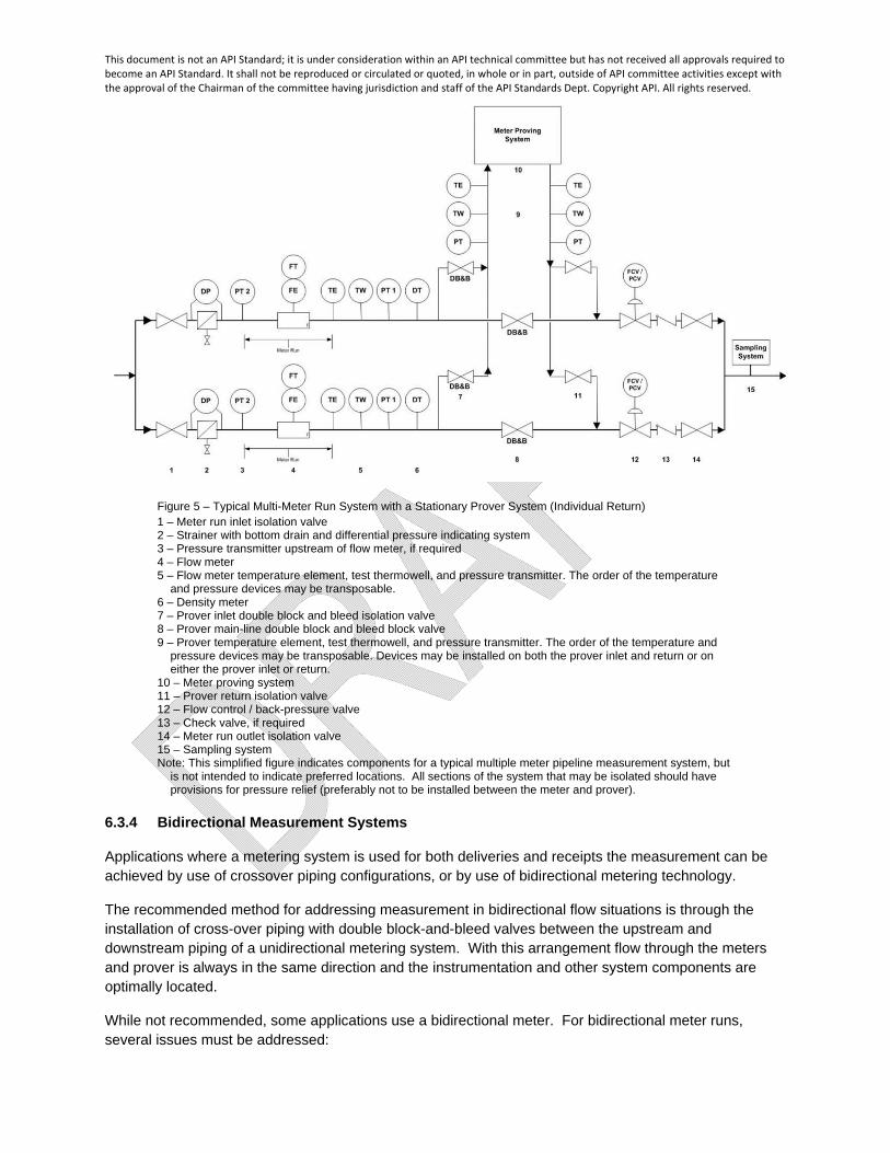
Figure 5 – Typical Multi-Meter Run System with a Stationary Prover System (Individual Return) 1 – Meter run inlet isolation valve 2 – Strainer with bottom drain and differential pressure indicating system 3 – Pressure transmitter upstream of flow meter, if required 4 – Flow meter 5 – Flow meter temperature element, test thermowell, and pressure transmitter. The order of the temperature
and pressure devices may be transposable. 6 – Density meter 7 – Prover inlet double block and bleed isolation valve 8 – Prover main-line double block and bleed block valve 9 – Prover temperature element, test thermowell, and pressure transmitter. The order of the temperature and
pressure devices may be transposable. Devices may be installed on both the prover inlet and return or on either the prover inlet or return.
10 – Meter proving system 11 – Prover return isolation valve 12 – Flow control / back-pressure valve 13 – Check valve, if required 14 – Meter run outlet isolation valve 15 – Sampling system Note: This simplified figure indicates components for a typical multiple meter pipeline measurement system, but
is not intended to indicate preferred locations. All sections of the system that may be isolated should have provisions for pressure relief (preferably not to be installed between the meter and prover).
6.3.4 Bidirectional Measurement Systems
Applications where a metering system is used for both deliveries and receipts the measurement can be achieved by use of crossover piping configurations, or by use of bidirectional metering technology.
The recommended method for addressing measurement in bidirectional flow situations is through the installation of cross-over piping with double block-and-bleed valves between the upstream and downstream piping of a unidirectional metering system. With this arrangement flow through the meters and prover is always in the same direction and the instrumentation and other system components are optimally located.
While not recommended, some applications use a bidirectional meter. For bidirectional meter runs, several issues must be addressed:

This document is not an API Standard; it is under consideration within an API technical committee but has not received all approvals required to become an API Standard. It shall not be reproduced or circulated or quoted, in whole or in part, outside of API committee activities except with the approval of the Chairman of the committee having jurisdiction and staff of the API Standards Dept. Copyright API. All rights reserved.
The flow conditioning section is designed for one direction, so duplicate systems shall be required.
Sampling systems are generally designed for one direction, so duplicate systems may be required.
Strainers are generally designed for one direction, so duplicate systems may be required.
Instrumentation, such as pressure and temperature measurement, may need to be duplicated.
Flow control valves may need to be duplicated.
Proving connections may need to be duplicated.
Meter factors shall be obtained for flow in each direction.
Care should be taken for meter types impacted by flow conditions when designing the location of the prover connections so that the flow profile through the meter run is not different during proving.
Figure 6 shows the typical valve configuration using four double block and bleed valves to achieve bidirectional flow through a unidirectional measurement system. To flow from point A to point B on Figure 6, valves V1 and V4 would be open and valves V2 and V3 would be closed. To flow from point B to point A on Figure 6, valves V3 and V2 would be open and valves V1 and V4 would be closed.
Figure 6 – Typical Bi-directional Metering System
Note: This simplified figure indicates components for a typical bidirectional meter measurement system, but is not intended to indicate preferred locations. All sections of the system that may be isolated should have provisions for pressure relief (preferably not to be installed between the meter and prover).
6.3.5 Viscous Metering Systems
Viscous hydrocarbons require special treatment or equipment when they are handled or stored because of resistance to flow. Many viscous liquids may need to be heated to lower the viscosity, and/or blended with a less viscous hydrocarbon to reduce viscosity and facilitate handling.

This document is not an API Standard; it is under consideration within an API technical committee but has not received all approvals required to become an API Standard. It shall not be reproduced or circulated or quoted, in whole or in part, outside of API committee activities except with the approval of the Chairman of the committee having jurisdiction and staff of the API Standards Dept. Copyright API. All rights reserved.
Special consideration should be taken for meters, auxiliary equipment, and fittings to accommodate or mitigate the effects of high temperatures during handling of heated liquids.
For heated viscous hydrocarbon systems, the following issues should be considered:
Installation of insulation on the system to maintain temperature control and for personnel safety.
Temperature limitations of, and effects on, system equipment. It is important that the temperature of the liquid be maintained within a reasonably close
range because meter accuracy is affected by variations in process and meter temperature as well as by the resultant viscosity change.
o Changes in temperature and viscosity may necessitate viscosity indexing, Reynolds Number indexing, and/or more frequent proving.
The liquid temperature shall be held below the point that may cause vaporization and result in inaccurate meter registration
It is difficult to separate entrained air or vapor from most viscous liquids. As viscosity increases, the time required for separating fine bubbles of air or vapor from the liquid increases. The removal of entrained bubbles requires a large air eliminator tank to effect separation.
o The type or size of air eliminator equipment depends on the amount of air to be encountered, the form in which it will occur, the pumping rate, the viscosity of the liquid, and the overall accuracy requirements of the installation.
Figure 7 below shows one method to maintain heat in the measurement system by circulating the liquid through a return line. The return line should tee off as close to the meter inlet as possible. In some applications, circulating the liquid through the entire meter system might be advisable; however, a means shall be provided to prevent registration on the meter counter during such period of circulation. Valves should be located in the return line to permit easy control of flow.
Figure 7 – Typical Meter Installation with Return Line for Maintaining Heat at the Meter 1 – Meter run inlet isolation valve 2 – Strainer with bottom drain and differential pressure indicating system 3 – Flow meter 4 – Double block and bleed valve on return line to storage

This document is not an API Standard; it is under consideration within an API technical committee but has not received all approvals required to become an API Standard. It shall not be reproduced or circulated or quoted, in whole or in part, outside of API committee activities except with the approval of the Chairman of the committee having jurisdiction and staff of the API Standards Dept. Copyright API. All rights reserved.
Note: This simplified figure indicates components for a typical meter installation with return line, but is not
intended to indicate preferred locations. The figure does not include all the equipment required for measurement and does not show any of the devices or equipment located downstream of a meter. See Figures 1 – 5 for typical measurement system drawings. All sections of the system that may be isolated should have provisions for pressure relief (preferably not to be installed between the meter and prover).
7 PROVER SELECTION CONSIDERATIONS
7.1 General
The first step when selecting a proving system is to determine whether to use a mobile (portable) prover or a stationary prover for the meter or meter system. This may depend on company measurement policy, connection agreements, and economics.
Once this decision has been made, selecting the type of prover is the next step. The decision for the prover type to be used is based on uncertainty requirements, frequency of proving, testing flow rates, liquid properties, measurement turndown requirements, prover dimensions and weight, environment, installation considerations, maintenance, and in some cases local agency approvals.
Although API MPMS Chapter 4 addresses centralized proving, this will not be discussed in this standard as it is not typical for pipeline, marine, FPSO or FSO applications.
7.2 Stationary vs Portable Provers
Stationary provers are typically considered for applications involving the following: a) Multiple meter runs b) High proving frequency c) Remote location d) Wide process or fluid property changes e) Contractual requirements f) Product quality contamination g) Health, safety, environmental, and regulatory considerations
Portable provers are typically considered for applications involving the following: a) Single meter run b) Using prover at multiple meter facilities c) Less frequent proving d) Single product lines e) Availability and accessibility of proving operator f) Contractual requirements where allowed g) Health, safety, environmental, and regulatory considerations
7.3 Prover Types
7.3.1 General
There are three types of provers used for meter calibration in the petroleum industry today, displacement provers, tank provers, and master meter provers.

This document is not an API Standard; it is under consideration within an API technical committee but has not received all approvals required to become an API Standard. It shall not be reproduced or circulated or quoted, in whole or in part, outside of API committee activities except with the approval of the Chairman of the committee having jurisdiction and staff of the API Standards Dept. Copyright API. All rights reserved.
7.3.2 Displacement Provers
The three types of displacement prover are bidirectional, unidirectional, and captive displacement. The displacement prover is typically used for pipeline, marine, FPSO or FSO applications. It is recommended that a design factor be applied when sizing the prover to ensure a minimum of 1 in 10,000 resolution. Typically, the design factor would be applied to the meter manufacturer’s nominal K-factor for sizing the prover calibrated volume.
To ensure full compatibility, it is recommended that the prover size be selected based on the maximum normal linear flow rate of the largest meter to be proved and the minimum design capacity for the smallest meter to be proved.
When using meters with manufactured pulses (Coriolis and ultrasonic meters), it is recommended to consult the meter and prover manufacturers when sizing displacement provers.
Refer to API MPMS Chapter 4.2 – Displacement Provers, for additional details on displacement provers.
7.3.3 Tank Provers
Tank provers are not typically used in pipeline, marine, FPSO or FSO applications because of limited volume capacity and non-continuous flow operation.
Refer to API MPMS Chapter 4.4 – Tank Provers, for additional details on tank provers.
7.3.4 Master Meter Prover
Master meter proving is used when proving by the direct method is impractical because of meter characteristics, logistics, time, space, economic, and safety considerations. However, it also allows for a much larger proving volume which may be helpful when calibrating meters having a non-uniform output.
Some aspects to consider when using master meter provers:
a) With the added uncertainty associated with the master meter, the overall measurement uncertainty for the custody transfer quantity is increased relative to other proving technologies.
b) The master meter accuracy could be affected by liquid viscosity, flow rate, density, temperature, or pressure.
c) Ideally master meters should be calibrated on the same fluid and flowing conditions that will be experienced by the line meter. Proving conditions that deviate from actual operating conditions will introduce uncertainty and inaccuracies to subsequent measurement.
Refer to API MPMS Chapter 4.5 – Master Meter Provers, for additional details on master meter provers.
8 QUALITY DETERMINATION
8.1 General
Product quality information (S&W, density, product composition, etc.) is required for determining the meter factor and the custody transfer quantity." See API MPMS Chapter 6.1A for more details.

This document is not an API Standard; it is under consideration within an API technical committee but has not received all approvals required to become an API Standard. It shall not be reproduced or circulated or quoted, in whole or in part, outside of API committee activities except with the approval of the Chairman of the committee having jurisdiction and staff of the API Standards Dept. Copyright API. All rights reserved.
8.2 Sampling
8.2.1 General
Depending upon the purpose, samples may be collected proportional to flow using an automatic sampling system or on a spot basis manually."
8.2.2 Automatic Sampling
Automatic sampling is used to collect a sample that represents the overall custody transfer quantity. The results from physical property tests of such a sample are used to determine the net quantity of the transfer and are typically documented on the measurement ticket.
There are two types of automatic sampling systems; inline sampling and sample loop. Both systems can produce representative samples if properly designed and operated. An automatic sampling system consists of stream conditioning (if required), a sample extraction device, a means of pacing the sampler proportional to flow or time, and the delivery of the extracted sample to a container or an analyzer. Please refer to API MPMS Chapter 8.2 (low vapor pressure hydrocarbons), API MPMS Chapter 8.5 (volatile crude oil, condensates and liquid products), and GPA 2174 (LPG) or ASTM D3700 (LPG) for more detailed discussions around the design of automated sampling systems and the need for and implementation of a calibration and verification procedure for sampling systems.
8.2.3 Manual Sampling
Manual sampling is used to collect a spot sample of a hydrocarbon liquid at a particular point in time or in conjunction with a particular activity, such as meter proving. In the case of meter proving, the result from a density test is used to determine the meter factor and is documented on the meter proving report.
Refer to API MPMS Ch. 8.1, section 8.4 (low vapor pressure hydrocarbons), ASTM D1265 (LPG), and GPA 2174 (LPG) or ASTM D3700 (LPG) for more information related to the design and operation of manual sampling systems.
8.3 Density
8.3.1 General
See API MPMS Chapter 6.1A for general guidance on density determination.
8.3.2 Density Meters
8.3.2.1 General
The API MPMS Chapter 9.4 provides guidance for online density meter selection, design, operation, installation, and calibration methods. Several common online density meter applications are addressed below.
8.3.2.2 Mass Determination
Density meters can be used for inferred mass measurement or direct mass measurement of NGL or LPG. Refer to API MPMS Chapter 14.7 for guidance on the two mass measurement methods.
This document is not an API Standard; it is under consideration within an API technical committee but has not received all approvals required to become an API Standard. It shall not be reproduced or circulated or quoted, in whole or in part, outside of API committee activities except with the approval of the Chairman of the committee having jurisdiction and staff of the API Standards Dept. Copyright API. All rights reserved.
8.3.2.3 Volume Correction Factor Determination
Volumetric flow meter systems require density to determine correction factors for the effects of temperature and pressure. Refer to the applicable sections of API MPMS Chapter 11 and API MPMS Chapter 12.
8.3.2.4 Product quality
Density measurement may be used to determine fluid density over a batch or detect changes in fluid density.
8.3.2.5 Interface Detection
Density measurement may be used during batch operations to identify product changes to initiate the opening or closing of the measurement ticket. Density readings may need to be corrected to standard conditions to prevent false interface readings due to changes in temperature or pressure.
8.4 Sediment and Water (S&W) Determination
Refer to API MPMS Ch. 6.1A for information for S&W determination.
8.5 Viscometers
Viscometers are online instruments used to measure flowing viscosity. Viscometers can be used for viscosity indexing or to initiate meter provings on viscosity changes.
8.6 Compositional Analysis
It is a requirement in the measurement of certain Natural Gas Liquid and Liquefied Petroleum Gas streams to obtain a compositional analysis which represents the individual hydrocarbon components of the metered product (see API MPMS 14.7/GPA 8182 for more details). The compositional analysis is performed to quantify the component volume metered, and the subsequent value of the product. Each hydrocarbon component (i.e. methane, ethane, propane etc.) has a different monetary value which must be calculated from the composition (see API MPMS 14.4 for more details).
Where composite samples are taken, they shall be analyzed by a laboratory equipped to handle NGL and LPG samples utilizing GPA Method 2177. In some cases, alternate methods of sampling may be acceptable such as spot sampling, or by the use of an online chromatograph.
8.7 Other Quality Considerations
Additional sampling may be requested or required to measure and/or verify product characteristics such as sulfur, RVP, octane, and flash point. Sampling and quality determination should be in accordance with industry standards and contractual agreements.
This document is not an API Standard; it is under consideration within an API technical committee but has not received all approvals required to become an API Standard. It shall not be reproduced or circulated or quoted, in whole or in part, outside of API committee activities except with the approval of the Chairman of the committee having jurisdiction and staff of the API Standards Dept. Copyright API. All rights reserved.
9 ADDITIONAL METERING SYSTEM COMPONENT DESIGN CONSIDERATIONS
9.1 Temperature
9.1.1 General
Temperature measurements are required for calculation of liquid quantities, prover volumes and flowing density at standard temperature. See API MPMS Chapters 6.1A, 7.4, 9.4, and applicable sections of MPMS Ch. 12.
9.1.2 Temperature Measurement at Meters
The objective when determining the temperature of metered liquid is to obtain an accurate liquid temperature inside the meter body.
The temperature sensor is preferred to be installed downstream of the meter consistent with any flow conditioning requirements.
9.1.3 Temperature Measurement at Provers
When determining the temperature of a liquid flowing through a prover for use in correcting for the thermal effects on the liquid and prover, the liquid temperature shall be measured as close to the prover inlet and/or outlet as is practical. When two measurements are taken, they shall be averaged to arrive at the prover temperature.
The goal is to determine the liquid temperature in the calibrated section of the prover. The preferred location of the temperature measurement is not more than 5 pipe diameters from the prover inlet and not more than 5 pipe diameters from the prover outlet. Consideration should be given to installing the temperature measurement equidistant from the prover inlet/outlet such that their average better represents the liquid temperature.
If a captive displacement prover is used, the temperature of the piston rod temperature is required.
If the prover inlet and outlet temperatures are the same, one temperature sensor is acceptable providing it is installed on the prover outlet.
9.1.4 Temperature Measurement at Density Meter
Temperature measurement is required for online density measurement to correct for their effects on the density meter and, if required, to correct the measured density to standard conditions.
For guidance on temperature and pressure effects and determination, refer to API Chapter 9.4.
9.1.5 Test Thermowells
A test thermowell should be provided close to temperature sensors that are permanently mounted in piping systems, such as in meter runs or meter prover systems to facilitate verification of temperature devices.
This document is not an API Standard; it is under consideration within an API technical committee but has not received all approvals required to become an API Standard. It shall not be reproduced or circulated or quoted, in whole or in part, outside of API committee activities except with the approval of the Chairman of the committee having jurisdiction and staff of the API Standards Dept. Copyright API. All rights reserved.
Test thermowells should be installed within 30 cm (12 inches) of the temperature transmitter or RTD location.
9.2 Pressure
9.2.1 General
Pressure measurements are required for calculation of liquid quantities, prover volumes and flowing density at standard pressure. See API MPMS Chapters 6.1A, and applicable section of MPMS Ch. 12.
9.2.2 Pressure with Meters
The objective when determining the pressure of metered liquid is to obtain an accurate liquid pressure inside the meter body.
The pressure sensor is preferred to be installed downstream of the meter consistent with any flow conditioning requirements.
9.2.3 Pressure Measurement on Provers
When determining the pressure of a liquid flowing through a prover for use in correcting for the hydraulic effects on the liquid and prover, the liquid pressure shall be measured as close to the prover inlet and outlet as is practical. When two measurements are taken, they shall be averaged to arrive at the prover pressure.
The goal is to determine the liquid pressure in the calibrated section of the prover. The preferred location of the pressure measurement is not more than 5 pipe diameters from the prover inlet and not more than 5 pipe diameters from the prover outlet. Consideration should be given to installing the pressure measurement equidistant from the prover inlet/outlet such that their average better represents the liquid pressure.
If the prover inlet and outlet pressures are the same, one pressure sensor is acceptable providing it is installed on the prover outlet.
9.2.4 Pressure Measurement at Density Meter
Pressure measurement is required for online density measurement to correct for their effects on the density meter and, if required, to correct the measured density to standard conditions.
For guidance on pressure effects and determination, refer to API Chapter 9.4.
9.2.5 Pressure Calibration and Verification
Pressure devices should be installed so that in-situ calibration and verification can be readily conducted. A possible method of meeting this recommendation is installation of gauge valve with quick connect for the calibration or verification device.
9.2.6 Other Pressure Considerations
It is important to maintain adequate pressure in the measurement system to prevent cavitation or flashing. See Chapter 6.1A for additional information on back pressure control.

This document is not an API Standard; it is under consideration within an API technical committee but has not received all approvals required to become an API Standard. It shall not be reproduced or circulated or quoted, in whole or in part, outside of API committee activities except with the approval of the Chairman of the committee having jurisdiction and staff of the API Standards Dept. Copyright API. All rights reserved.
9.3 Flow Conditioning
For meter types that are dependent on flow profile, such as turbine and ultrasonic meters, the measurement system shall include a flow conditioning section upstream and downstream of each meter per manufacturer recommendations. See Chapter 5.3 and Chapter 5.8 for a full description of the arrangement and details for each meter technology.
9.4 Strainers
Strainers are recommended upstream of the meter to remove contaminants from the flow stream that may cause fouling or damage to meters, valves, instrumentation, sampling equipment, and the prover. The strainer should be designed to minimize pressure drop at maximum flow rate and viscosity. A maximum of two to five psi pressure drop is a commonly used value for design considerations.
A means of monitoring the differential pressure across the strainer is recommended. Increased differential pressure could indicate that the strainer requires cleaning and could cause a flow profile distortion. Possible methods of meeting this recommendation is a pressure sensor/gauge located on both sides of the strainer or a single differential pressure transmitter/gauge installed across the strainer.
Ensure the design of the strainer does not influence the type of metering technology selected (consult meter manufacturer). The strainer basket perforations and/or mesh size should be sized in accordance with the meter manufacturer’s recommendations.
9.5 Insulation/Heating Systems
9.5.1 Insulation
Insulation of the system may be required to maintain proper process liquid temperature, or for personnel safety. It can also be installed to maintain system equipment within recommended temperature limits.
9.5.2 Heating
In addition to insulation, it may be necessary to add a heat source to maintain the process liquid and/or the equipment within required temperature range.
9.6 Valves
9.6.1 General
Anywhere a leak through a valve will cause a measurement error (e.g. prover mainline block valves, meter and prover drain valves, prover diverter or interchange valve, bypass valves) a means to verify the valve integrity shall be provided.
9.6.2 Isolation Valves
For maintenance and isolation of meter runs, valves should be installed at both ends of each meter assembly so that the meter and other components can be maintained without having to shut down product flow. The valve upstream of the measurement device should be chosen to ensure negligible disturbance to the flow profile which could adversely affect the meter performance.
This document is not an API Standard; it is under consideration within an API technical committee but has not received all approvals required to become an API Standard. It shall not be reproduced or circulated or quoted, in whole or in part, outside of API committee activities except with the approval of the Chairman of the committee having jurisdiction and staff of the API Standards Dept. Copyright API. All rights reserved.
9.6.3 Prover Manifold Valves
Prover manifold valves are used to direct the flow to and from the prover, and to ensure all liquid from the meter under test is being passed through the prover, and no fluid is being introduced between the meter and the prover. All hard-piped valves between the meter and the prover shall be double block and bleed type.
9.6.4 Bypass Valves
Bypass valves are a means of diverting the liquid flow around the meter for either equipment maintenance or problems with the flowing stream. All bypass valves shall be double block and bleed type. Please refer to Chapter 6.1A.
9.6.5 Double Block and Bleed Valves
A double block-and-bleed valve is a single valve with two seating surfaces that, in the closed position, provides a seal against pressure from both ends of the valve, with a means of vent or bleed the cavity between the seating surfaces to ensure valve integrity. The valve cavity should have a thermal relief to prevent valve damage.
9.6.6 Prover Four-way or Interchange valves
The bidirectional prover four-way or unidirectional interchange valve shall establish complete liquid sealing while the prover displacer travels through the prover calibrated section. The four-way or interchange bleed port should be configured to verify valve integrity and should allow for visual or electronic means of seal verification. Refer to API MPMS Chapter 4.2 – Displacement Provers, for additional details on Displacement provers.
9.6.7 Control Valves
9.6.7.1 General
Control valves are used for back pressure control, flow balancing, and flow control during proving operations. See API MPMS Chapters 5.2, 5.3, 5.6 and 5.8 for specific requirements.
9.6.7.2 Back Pressure Control Valves
Back pressure control valves are used to ensure the liquid in the measurement system remain above the equilibrium vapor pressure.
9.6.7.3 Flow Control Valves
Control of flow may be necessary in some application such as marine loading. Flow control is sometimes required to ensure meters are maintained within their rated capacity, particularly where meters of different sizes are provided in a multiple meter run system. Control of the flow rate during meter proving can be accomplished using control valves on opposing meters (meters other than the one being proved) in multiple meter run systems.
NOTE: If properly selected, a single control valve can be used to provide the required minimum back pressure and flow control.
9.6.8 Check Valves
A check valve is commonly provided to prevent back flow through the meter and/or prover.

This document is not an API Standard; it is under consideration within an API technical committee but has not received all approvals required to become an API Standard. It shall not be reproduced or circulated or quoted, in whole or in part, outside of API committee activities except with the approval of the Chairman of the committee having jurisdiction and staff of the API Standards Dept. Copyright API. All rights reserved.
9.6.9 Drain Valves
Metering system designs should include taps at low points so that the system may be drained before maintenance. Use of drains between the meter and the prover should be minimized. Any drain that can affect measurement accuracy must be equipped with a means to prevent leaks or verify that no leaks exist.
9.6.10 Vent Valves
Metering systems designs should include high point vents to eliminate air, vapors, or non-condensable gases. Use of vents between the meter and the prover should be minimized. Any vent that can affect measurement accuracy must be equipped with a means to prevent leaks or verify that no leaks exist.
9.6.11 Pressure Relief Valves
Relief valves protect the system from the effects of over-pressuring. Installation of thermal relief valves between the meter and prover and between the metering system and the custody transfer point should be minimized. If required in one of these locations, a thermal relief valve should be provided with a means to detect leakage. See API MPMS 6.1A for more details related to installation and leak detection.
9.7 Air/Vapor Eliminators
9.7.1 General
Each metering system shall be designed to prevent air or vapor from passing through it. If necessary, air/vapor elimination equipment shall be installed upstream of the metering system. See API MPMS Chapter 6.1A for more details.
9.7.2 Pipeline Operations
In a metering station, if a high vacuum (negative head) condition could exist, a block and/or check valve should be installed in vent lines to prevent air being drawn into the air remover. Care should be taken during storage tank operations to ensure a minimum amount of vapor enters the liquid meter systems during commodity change or “drain-dry” operations.
9.7.3 Marine Loading and Unloading Vessel Requirements
Marine loading does not generally present a severe air problem because tankage, manifolds, and lines are normally kept full of liquid. However, air/vapor elimination equipment may still be required.
During marine unloading, air may be introduced each time load-arm connections are made to the carrier. Air/vapor may also be introduced during a vessel’s stripping operations. For marine unloading, operations must ensure the piping from the vessel to the air eliminator is full of product prior to start of the measurement ticket, refer to API MPMS Chapter 17.6 for further details. The air eliminator should also be equipped with a means of determining level before and after the unloading operation.

This document is not an API Standard; it is under consideration within an API technical committee but has not received all approvals required to become an API Standard. It shall not be reproduced or circulated or quoted, in whole or in part, outside of API committee activities except with the approval of the Chairman of the committee having jurisdiction and staff of the API Standards Dept. Copyright API. All rights reserved.
9.8 Automation and Controls
9.8.1 Flow Computers
A flow computer receives inputs from the primary device and the secondary devices. This data is either processed in the flow computer or transferred to a central measurement calculation system to determine the measurement ticket. Signals can be analog, digital, or digital communication protocol. The flow computer may be used to provide control signals to automatic samplers, control valves, or initiate and perform meter proving operations. For further information on flow computers, refer to API MPMS Ch. 21.2. Due to complexity of calculations and strict requirements on processing time, the use of flow computers is recommended.
9.8.2 PLCs
Programmable Logic Controllers (PLCs) in pipeline and marine loading/unloading measurement systems are typically used to monitor and control the portions of metering system that are not directly involved in the measurement of liquid hydrocarbons. Motor operated meter isolation and prover routing valves are generally separated from the flow measurement computer and connected to a PLC. This arrangement allows separation of operation and measurement functionality. Thus, the PLC often controls valve sequencing, brings meter runs on and off line, and aligns the proving device. Because the PLC has logic capability, it can manage alarm conditions that could affect measurement, such as strainer shutdown for high differential pressure. Furthermore, the PLC may control auxiliary equipment like pumps, control valves, or sample extractors.
9.8.3 Supervisory and Control Systems
A supervisory system is optional and is most often used on larger and more complex applications. The supervisory system is a computer based or panel type operator interface to an individual or multiple meter run systems. The HMI may provide a graphical representation of the metering system to the operator. The supervisory system may be used to perform manual or automatic operations such as setting sample rate, printing and archiving tickets, initiating provings, selecting and sequencing meter runs, generating reports and other functions. In addition to the flow computer, certain functions (e.g. measurement ticket, events/alarm report) of the supervisory systems may form part of the measurement system audit trail.
9.8.4 Local Totalizers
Local totalizers can be used to back-up the primary totalizers and provide a local indication of totalized flow to the operator.
10 OPERATIONAL CONSIDERATIONS AND MAINTENANCE
10.1 Volume or Mass Calculation
Calculations used to produce a measurement ticket are selected based on the measured liquid fluid properties and whether volumetric or mass measurement techniques are being applied. API MPMS Ch. 21.2 (volume), API MPMS Ch. 21.2, Addendum 1, Section 2 (mass), and GPA 8182 outline calculation requirements. User should consider verification of measurement ticket calculations in accordance with

This document is not an API Standard; it is under consideration within an API technical committee but has not received all approvals required to become an API Standard. It shall not be reproduced or circulated or quoted, in whole or in part, outside of API committee activities except with the approval of the Chairman of the committee having jurisdiction and staff of the API Standards Dept. Copyright API. All rights reserved.
API MPMS Chapter 12 and GPA 8182 and verification of flow computer configuration on a user defined frequency; typically, annually, or after changes to the configuration.
10.2 Documentation and Records
Provisions should be included to capture and retain documents and records (e.g., alarm event logs, etc.) as defined by company policy, the connection or other agreements and/or applicable government regulations.
An audit trail defines the documents and records necessary to allow the measurement ticket to be audited (see API MPMS 21.2). Elements of the audit trail are:
Configuration logs Event and Alarm log Pressure, temperature, and density verification records Prover calibration certificate Chromatograph calibration records (if applicable) Calibration standard certificates
10.3 Strainers
A maintenance program should be followed for inspection and cleaning of strainer baskets if no differential pressure indication is provided.
If a means of monitoring differential pressure is provided, the pressure across the strainer should be monitored regularly. High differential pressure is an indication that the basket contains debris and should be cleaned. Zero or abnormally low differential pressure could be an indication that the basket may be ruptured and the strainer is not providing adequate protection for downstream equipment.
10.4 Valves
10.4.1 Double Block and Bleed Valves
All DB&B valves shall be verified at a user-defined frequency. If the valve fails to seal, the proving shall be aborted and the valve inspected.
10.4.2 Prover Four-way or Interchange valves
Verify the prover four-way or interchange valve is sealed during proving operation at a user-defined frequency. If the valve fails to seal, the proving shall be aborted and the valve inspected. For further guidance, see API MPMS 4.8.
10.5 Volume/Mass Primary Measurement Devices
Reference the appropriate API MPMS Chapter 5 for the applicable operation and maintenance considerations for the selected metering technology.

This document is not an API Standard; it is under consideration within an API technical committee but has not received all approvals required to become an API Standard. It shall not be reproduced or circulated or quoted, in whole or in part, outside of API committee activities except with the approval of the Chairman of the committee having jurisdiction and staff of the API Standards Dept. Copyright API. All rights reserved.
10.6 Secondary Measurement Devices
10.6.1 Provers
Refer to API MPMS Chapter 4.8 for operation and maintenance requirements for provers.
10.6.2 Sampling Systems
Refer to API MPMS Chapter 8.2 for operation and maintenance requirements for sampling systems.
10.6.3 Density Meters
Refer to API MPMS Chapter 9.4 for operation and maintenance requirements; including the determination of density meter factors (DMF), for density meters.
10.6.4 Temperature and Pressure Devices
The verification or calibration of temperature and pressure measuring devices is necessary to ensure they comply with company, regulatory, or contractual requirements. See API MPMS 6.1A for further information.
10.6.5 Online Gas Chromatographs
Refer to GPA Method 2177 for operation and maintenance requirements for on-line gas chromatographs.
10.6.6 Tertiary Measurement Devices
Tertiary Measurement devices consist of a flow computer. A flow computer maintenance program may include:
Verification of the configuration by comparing a previous configuration against the current configuration
Verification of the flow computer’s input/output wiring
This document is not an API Standard; it is under consideration within an API technical committee but has not received all approvals required to become an API Standard. It shall not be reproduced or circulated or quoted, in whole or in part, outside of API committee activities except with the approval of the Chairman of the committee having jurisdiction and staff of the API Standards Dept. Copyright API. All rights reserved.
Bibliography
[1] API MPMS Chapter 4.2, Displacement Provers [2] API MPMS Chapter 4.5, Master Meter Provers [3] API MPMS Chapter 4.8, Operation of Proving Systems [4] API MPMS Chapter 5.2, Measurement of Liquid Hydrocarbons by Displacement Meters [5] API MPMS Chapter 5.3, Measurement of Liquid Hydrocarbons by Turbine Meters [6] API MPMS Chapter 5.6, Measurement of Liquid Hydrocarbons by Coriolis Meters [7] API MPMS Chapter 5.8, Measurement of Liquid Hydrocarbons by Ultrasonic Flow Meters [8] API MPMS Chapter 7.4, Dynamic Temperature Measurement [9] API MPMS Chapter 8.1, Manual Sampling of Petroleum and Petroleum Products [10] API MPMS Chapter 8.2, Standard Practice for Automatic Sampling of Petroleum and
Petroleum Products [11] API MPMS Chapter 8.5, Standard Practice for Manual Piston Cylinder Sampling of
Volatile Crude Oils, Condensates and Liquid Petroleum Products [12] API MPMS Chapter 9.4, Continuous/On-line Density Measurement and Applications [13] API MPMS Chapter 14.4, Converting Mass of Natural Gas Liquids to Equivalent Liquid
Volumes [14] API MPMS Chapter 14.7, Mass Measurement of Natural Gas Liquids and Other
Hydrocarbons API MPMS Chapter 17.6, Guidelines for Determining Fullness of Pipelines Between Vessels and Shore Tanks
[15] API MPMS Chapter 21.2, Electronic Liquid Volume Measurement Using Positive Displacement and Turbine Meters
[16] API MPMS Chapter 21.2, Addendum 1, Flow Measurement Using Electronic Metering Systems, Inferred Mass
[17] ASTM D1265, Standard Practice for Sampling Liquefied Petroleum (LP) Gases (Manual Method)
[18] ASTM D3700, Standard Practice for Obtaining LPG Samples Using a Floating Piston Cylinder
[19] GPA 2174, Obtaining Liquid Hydrocarbon Samples for Analysis by Gas Chromatography [20] GPA 8182, Standard for Mass Measurement of Natural Gas Liquids