Manual of Petroleum Measurement Standards Chapter 17 ...ballots.api.org/copm/coma/ballots/docs/Ch...
38
This document is not an API standard; it is under consideration within an API committee but has not received all approvals required to become an API standard. You agree not to reproduce or circulate or quote, in whole or in part, this document outside of API, or submit it to any other organization or standards bodies (whether national, international, or other) except with the approval of the Chairman of the Committee having jurisdiction, If you do not agree with these conditions please immediately destroy all copies of the document. Copyright API, Washington D.C. All Rights Reserved API Manual of Petroleum Measurement Standards Chapter 17 - Marine Measurement Section 14 - Measurement of Bulk Cargoes by Draft Survey Part 1 – Ocean-Going Vessels 1 ST EDITION, DATE XXXXX LATEST REVISION 8/7/18
Transcript of Manual of Petroleum Measurement Standards Chapter 17 ...ballots.api.org/copm/coma/ballots/docs/Ch...

This document is not an API standard; it is under consideration within an API committee but has not received all approvals required to become an API standard. You agree not to reproduce or circulate or quote, in whole or in part, this document outside of API, or submit it to any other organization or standards bodies (whether national, international, or other) except with the approval of the Chairman of the Committee having jurisdiction, If you do not agree with these conditions please immediately destroy all copies of the document. Copyright API, Washington D.C. All Rights Reserved
API Manual of Petroleum Measurement Standards Chapter 17 - Marine Measurement Section 14 - Measurement of Bulk Cargoes by Draft Survey Part 1 – Ocean-Going Vessels
1ST EDITION, DATE XXXXX LATEST REVISION 8/7/18

This document is not an API standard; it is under consideration within an API committee but has not received all approvals required to become an API standard. You agree not to reproduce or circulate or quote, in whole or in part, this document outside of API, or submit it to any other organization or standards bodies (whether national, international, or other) except with the approval of the Chairman of the Committee having jurisdiction, If you do not agree with these conditions please immediately destroy all copies of the document. Copyright API, Washington D.C. All Rights Reserved
Foreword
Nothing contained in any API publication is to be construed as granting any right, by implication or otherwise, for the manufacture, sale, or use of any method, apparatus, or product covered by letters patent. Neither should anything contained in the publication be construed as insuring anyone against liability for infringement of letters patent.
Shall: As used in a standard, “shall” denotes a minimum requirement in order to conform to the specification.
Should: As used in a standard, “should” denotes a recommendation or that which is advised but not required in order to conform to the specification.
This document was produced under API standardization procedures that ensure appropriate notification and participation in the developmental process and is designated as an API standard. Questions concerning the interpretation of the content of this publication or comments and questions concerning the procedures under which this publication was developed should be directed in writing to the Director of Standards, American Petroleum Institute, 1220 L Street, N.W., Washington, D.C. 20005. Requests for permission to reproduce or translate all or any part of the material published herein should also be addressed to the director.
Generally, API standards are reviewed and revised, reaffirmed, or withdrawn at least every five years. A one-time extension of up to two years may be added to this review cycle. Status of the publication can be ascertained from the API Standards Department, telephone (202) 682-8000. A catalog of API publications and materials is published annually by API, 1220 L Street, N.W., Washington, D.C. 20005.
Suggested revisions are invited and should be submitted to the Standards Department, API, 1220 L Street, NW, Washington, D.C. 20005, [email protected].

This document is not an API standard; it is under consideration within an API committee but has not received all approvals required to become an API standard. You agree not to reproduce or circulate or quote, in whole or in part, this document outside of API, or submit it to any other organization or standards bodies (whether national, international, or other) except with the approval of the Chairman of the Committee having jurisdiction, If you do not agree with these conditions please immediately destroy all copies of the document. Copyright API, Washington D.C. All Rights Reserved
Table of Contents
1. Scope
2. Normative References
3. Terms & Definitions
4. Significance and Use (Purpose)
5. Health & Safety
6. Communication and Vessel Familiarization
6.1 Key Meeting
7. The Survey
7.1 Tools required for the survey 7.2 Determining the Draft
7.2.1 Draft Marks 7.2.2 Reading the Draft Marks
7.2.3 Factors Affecting Reading the Draft Marks 7.2.4 Alternative Methods of Reading the Draft 7.3 Measuring Variable and Consumable Items 7.3.1 Ballast Tanks and Void Spaces 7.3.2 Fresh Water and Grey Water 7.3.3 Fuel Oil (Bunkers) 7.3.4 Determining Liquid Volumes in a Tank 7.3.5 Determining the Weight of Liquid Volumes in a Tank 7.3.5.1 Determining Ballast Water Density 7.3.6 Determining the Density of the Water in which the Vessel is Floating 7.3.6.1 Taking the Samples 7.3.6.2 Reading the Hydrometer
8 Calculation Process 8.1 Adjusting the Draft Readings to the Perpendiculars 8.2 Calculating the Three-Quarter [¾] Mean Draft

This document is not an API standard; it is under consideration within an API committee but has not received all approvals required to become an API standard. You agree not to reproduce or circulate or quote, in whole or in part, this document outside of API, or submit it to any other organization or standards bodies (whether national, international, or other) except with the approval of the Chairman of the Committee having jurisdiction, If you do not agree with these conditions please immediately destroy all copies of the document. Copyright API, Washington D.C. All Rights Reserved
8.3 Determining the Corrected Displacement 8.3.1 First Trim Correction 8.3.2 Second Trim Correction 8.3.3 List Correction 8.3.4 Density Correction 8.4 Determination of Net Weights 8.4.1 Net (Light-ship) Weight – Initial Survey 8.4.2 Stated Light-ship Weight and Constant 8.4.3 Final Loaded or Discharged Quantity 9 Reporting 9.1 Initial and Final Survey Excel Spreadsheet 9.1.1 Discrimination Data Level 9.1.2 Initial Survey Worksheet 9.1.3 Final Survey Worksheet 9.1.4 Summary Report on Draft Survey Measurement
Annex A – Tools for the survey Annex B – Using a Manometer
Annex C – Draft Survey Hydrometers Annex D – Salinity Refractometers Annex E – Survey Template Bibliography

This document is not an API standard; it is under consideration within an API committee but has not received all approvals required to become an API standard. You agree not to reproduce or circulate or quote, in whole or in part, this document outside of API, or submit it to any other organization or standards bodies (whether national, international, or other) except with the approval of the Chairman of the Committee having jurisdiction, If you do not agree with these conditions please immediately destroy all copies of the document. Copyright API, Washington D.C. All Rights Reserved
API MPMS Chapter 17.14.1 Measurement of Bulk Cargoes by Draft Survey
Part 1 – Ocean-Going Vessels
1. Scope
This document describes the procedure for determining the transferred quantity of non-liquid petroleum products loaded onto or discharged from ocean going vessels by draft survey. This procedure is not an alternative where effective static or dynamic liquid measurement methods can be used.
2. Normative References
The following documents are referred to in the text in such a way that some of all of their content constitutes requirement of this document. For dated references, only the edition cited applies. For undated references, the latest edition of the referenced document (including any addenda) applies.
API MPMS Chapter 11—Physical Properties Data, Section 5—Density/Weight /Volume Intraconversion.
API MPMS Chapter 17—Marine Measurement, Section 4—Method for Quantification of Small
Volumes on Marine Vessels (OBQ/ROB)
3. Terms and Definitions
For the purposes of this document, the following definitions apply.
3.1 Aft Draft The distance from the bottom of the keel to the waterline on aft perpendicular.
3.2 Aft Perpendicular The aft perpendicular is a vertical line drawn at the intersection of the waterline at the vessel’s summer draft marks and the aft edge of the rudder post, or in the case of most modern ships where no rudder post is fitted, the center line of the rudder stock.

This document is not an API standard; it is under consideration within an API committee but has not received all approvals required to become an API standard. You agree not to reproduce or circulate or quote, in whole or in part, this document outside of API, or submit it to any other organization or standards bodies (whether national, international, or other) except with the approval of the Chairman of the Committee having jurisdiction, If you do not agree with these conditions please immediately destroy all copies of the document. Copyright API, Washington D.C. All Rights Reserved
3.3 Apparent Trim Is the difference between the forward draft and the aft draft as read and not corrected to the vessel’s perpendiculars.
3.4 Apparent Weight Weight in air
3.5 Beam The transverse dimensions in a horizontal plane expressing the breadth or width of the ship or ocean going barge, and measured from side shell plating to side shell plating.
3.6 Corrected Mean Draft [CMD] (a) An ocean going vessel's corrected mean draft is the draft as calculated at the center of flotation and may not be equal to the average of the drafts forward and aft
(b) An inland barge's final draft is calculated using the Quarter Mean method.
3.7 Corrected Trim Is the apparent trim corrected to the perpendiculars.
3.8 Deadweight A measure of how much weight a ship or barge is carrying or can safely carry. It is the sum of the weights of cargo, fuel, fresh water, ballast water, provisions, passengers, and crew. It does not include the weight of the ship or barge.
3.9 Vessel Displacement The total weight of the marine vessel and its contents. 3.10 Draft The depth of a vessel below the water line measured from the surface of the water to the bottom of the vessel’s keel.
This document is not an API standard; it is under consideration within an API committee but has not received all approvals required to become an API standard. You agree not to reproduce or circulate or quote, in whole or in part, this document outside of API, or submit it to any other organization or standards bodies (whether national, international, or other) except with the approval of the Chairman of the Committee having jurisdiction, If you do not agree with these conditions please immediately destroy all copies of the document. Copyright API, Washington D.C. All Rights Reserved
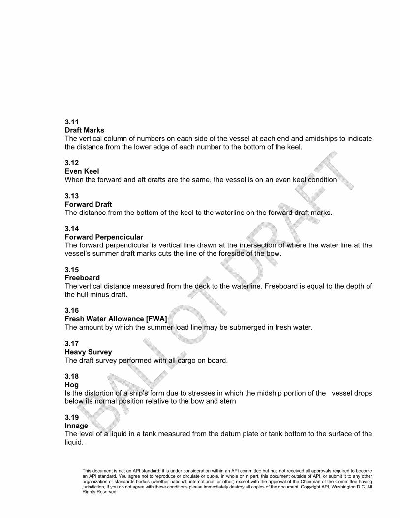
3.11 Draft Marks The vertical column of numbers on each side of the vessel at each end and amidships to indicate the distance from the lower edge of each number to the bottom of the keel.
3.12 Even Keel When the forward and aft drafts are the same, the vessel is on an even keel condition. 3.13 Forward Draft The distance from the bottom of the keel to the waterline on the forward draft marks.
3.14 Forward Perpendicular The forward perpendicular is vertical line drawn at the intersection of where the water line at the vessel’s summer draft marks cuts the line of the foreside of the bow.
3.15 Freeboard The vertical distance measured from the deck to the waterline. Freeboard is equal to the depth of the hull minus draft.
3.16 Fresh Water Allowance [FWA] The amount by which the summer load line may be submerged in fresh water. 3.17 Heavy Survey The draft survey performed with all cargo on board.
3.18 Hog Is the distortion of a ship’s form due to stresses in which the midship portion of the vessel drops below its normal position relative to the bow and stern
3.19 Innage The level of a liquid in a tank measured from the datum plate or tank bottom to the surface of the liquid.

This document is not an API standard; it is under consideration within an API committee but has not received all approvals required to become an API standard. You agree not to reproduce or circulate or quote, in whole or in part, this document outside of API, or submit it to any other organization or standards bodies (whether national, international, or other) except with the approval of the Chairman of the Committee having jurisdiction, If you do not agree with these conditions please immediately destroy all copies of the document. Copyright API, Washington D.C. All Rights Reserved
3.20 Longitudinal Center of Flotation [LCF] The longitudinal distance from a point of reference (usually midships) to the geometric center of the of the water-plane area when the hull is not moving. It is the position about which the ship will trim and will move as the shape of the water plane area changes as weights are loaded or discharged. 3.21 Lightship The weight of the ship complete in all respects when empty, but with full equipment, engine spares, lubricating oils in the engine and water in the boiler. 3.22 List (a)The leaning or inclination of a vessel, expressed in degrees port or degrees starboard (b) the transverse deviation of a vessel from the upright position expressed in degrees.
3.23 Length Between the Perpendiculars [LBP] The horizontal distance between the forward and after perpendiculars. 3.24 Moment to Change Trim 1 Centimeter [MCTC] It is the moment (weight x distance) required to change the trim of the vessel by 1 centimeter 3.25 Moment to Change Trim 1 Inch [MCTI] It is the moment (weight x distance) required to change the trim of the vessel by 1 inch 3.26 Means of Means of Drafts As applicable to draft surveys, this is the arithmetic average of the forward and aft mean drafts.
3.27 SAG Is the distortion of a l ship’s form due to stresses in which the midship portion of the vessel drops below its normal position relative to the bow and stern.
3.28 Sounding Same as innage.

This document is not an API standard; it is under consideration within an API committee but has not received all approvals required to become an API standard. You agree not to reproduce or circulate or quote, in whole or in part, this document outside of API, or submit it to any other organization or standards bodies (whether national, international, or other) except with the approval of the Chairman of the Committee having jurisdiction, If you do not agree with these conditions please immediately destroy all copies of the document. Copyright API, Washington D.C. All Rights Reserved
3.29 Stability Book A book, in paper and/or digital format, provided to all ships, which includes a section of hydrostatic particulars giving data for different drafts. Also referred to as the vessel’s hydrostatic tables.
3.20 Tons Per Centimeter Immersion [TPC] It is the weight that must be loaded or discharged to change the ships mean draft 1 centimeter. 3.21 Tons Per Inch Immersion [TPI] It is the weight that must be loaded or discharged to change the ships mean draft 1 inch 3.22 Ullage Is the distance from the surface of the liquid in a tank to the reference gauge point of the tank. 3.23 Waterline/Water line The length of the line created by the surface of the flotation water from the point where it contacts the bow to the point where it contacts the stern of the vessel.
3.24 Weight in Air: The weight in air of a substance is its weight in vacuum, reduced by its buoyancy (in air).
4. Significance and Use
The purpose of this section of the standard is to provide uniform draft survey methods to determine the weight of cargoes transferred to or from ocean going vessels.
Note: The draft survey process is not cargo specific and can be used on any type of cargo, although it is rarely used on liquid cargoes.
The standard will address detailed procedures for taking the necessary measurements in the field, performing calculations and reporting the results.

This document is not an API standard; it is under consideration within an API committee but has not received all approvals required to become an API standard. You agree not to reproduce or circulate or quote, in whole or in part, this document outside of API, or submit it to any other organization or standards bodies (whether national, international, or other) except with the approval of the Chairman of the Committee having jurisdiction, If you do not agree with these conditions please immediately destroy all copies of the document. Copyright API, Washington D.C. All Rights Reserved
5. Health and Safety Precautions
Personnel involved with the measuring and sampling of petroleum and petroleum-related substances should be familiar with their physical and chemical characteristics, including potential for fire, explosion, and reactivity, and with the appropriate emergency procedures as well as potential toxicity and health hazards. Personnel should comply with their individual company safe operating practices.
6. Communication and Vessel Familiarization The Master of the vessel should be advised in adequate time that a draft survey will be conducted. The subject to the safety of the vessel is considered to ensure that ballast tanks are either fully pressed up or empty and the vessel is upright and with a trim that is within the limits of the tank calibration tables. 6.1 Key Meeting Draft surveys should be undertaken, with the vessel’s Chief Officer and Chief Engineer or their appointed deputies, the details of which are usually discussed at the key meeting. The following items are typically reviewed at the key meeting:
● Cargo to be loaded or discharged, quantity and stowage. ● Cargo to be stopped by ship or shore ● Cargo load or discharge plan sequence ● Topping or trimming requirements ● Position of cranes and anchors ● Where was the ballast taken – river, harbor or at sea ● Will the vessel take bunkers, fresh water or stores during cargo operations? ● Is there any water in the swimming pool ● Hydrostatic particulars such as light-ship, constant ● Have any modifications been made to the vessel and was the stability book updated
The surveyor should familiarize him or herself with the vessels particulars by reviewing its general arrangement plan to confirm items such as the number and location of ballast, fresh water and oil bunker tanks on the vessel in addition to the various cargo and non-cargo spaces.

This document is not an API standard; it is under consideration within an API committee but has not received all approvals required to become an API standard. You agree not to reproduce or circulate or quote, in whole or in part, this document outside of API, or submit it to any other organization or standards bodies (whether national, international, or other) except with the approval of the Chairman of the Committee having jurisdiction, If you do not agree with these conditions please immediately destroy all copies of the document. Copyright API, Washington D.C. All Rights Reserved
7. The Survey
Draft surveying is a commercially acceptable form of weighing that is based on Archimedes Principle, which states that anything that floats will displace an amount of the liquid [it is floating in] equal to its own weight. The weight [or displacement] of the ship is determined both before and after cargo operations; and, after adjustments are made for differences in ballast water and other changeable items, the difference between these two weights is the weight of the cargo loaded or discharged. The weight of water that a ship displaces can be determined from the ship’s displacement table, using the corrected mean draft. Several corrections are required in addition to the quantities of ballast and other changeable items so as to obtain the net weights. Corrections are needed mainly because of the aspect of the ship in the floatation water such as trim and list, a variable center of flotation and the fact that the draft marks are not usually placed on the ship’s perpendiculars. Briefly, the daft survey process consists of:
1) Gathering all of the required measurement equipment needed to perform the survey 2) Reading the draft marks
a) Adjusting fore and aft draft marks to their perpendiculars and midships, as appropriate 3) Measuring the ballast and fuel tanks and other changeable items, including checking non-
cargo void spaces such as bilges and cofferdams. 4) Sampling the water that the vessel is floating in and determining its density 5) Calculating the mean draft according to the draft marks 6) Determine the corrected displacement
a) First trim correction b) Second Trim Correction c) List correction, if needed d) Density correction
7) Determination of net weights 7.1 Tools required for the survey
The tools that are typically required in order to carry out a draft survey are detailed in Annex A (informative). This list is not exhaustive and additional or other tools may be used.

This document is not an API standard; it is under consideration within an API committee but has not received all approvals required to become an API standard. You agree not to reproduce or circulate or quote, in whole or in part, this document outside of API, or submit it to any other organization or standards bodies (whether national, international, or other) except with the approval of the Chairman of the Committee having jurisdiction, If you do not agree with these conditions please immediately destroy all copies of the document. Copyright API, Washington D.C. All Rights Reserved
7.2 Determining the Draft 7.2.1 Draft Marks Draft marks indicate the depth at which the ship is floating and can be in metric or U.S. Customary units. Metric marks are 10cm high and placed 10cm apart. The marks themselves are 2 cm wide. An example of typical metric marks is shown in figure 1. In this example if the waterline was exactly at the bottom of the “114” mark, the draft would be 11.40 m. If it was exactly at the top of the “114” mark the draft would be 11.50 m
U.S. Customary unit marks (also referred to as English or Imperial units) are 6 inches high and are placed 6 inches apart. The marks are 1 inch wide. In the example in figure 2, if the waterline was exactly at the bottom of the “38” mark, the draft would be 38’ 00”. If it was exactly at the top of the “38” mark, the draft would be 38’
06”. The example also shows draft marks in Roman Numerals, however, they are read the same as the Arabic numerals. 7.2.2 Reading the Draft Marks Draft marks should be read to the nearest 1 cm for metric marks and the nearest ½ inch for US Customary marks. It is preferable to read the draft marks from a tug or launch. They must be read on both sides of the vessel; specifically:
● Forward port and starboard, ● Midships port and starboard, and; ● Aft port and starboard.
Draft marks should be read by the surveyor as close to the water line as possible to reduce parallax error.

This document is not an API standard; it is under consideration within an API committee but has not received all approvals required to become an API standard. You agree not to reproduce or circulate or quote, in whole or in part, this document outside of API, or submit it to any other organization or standards bodies (whether national, international, or other) except with the approval of the Chairman of the Committee having jurisdiction, If you do not agree with these conditions please immediately destroy all copies of the document. Copyright API, Washington D.C. All Rights Reserved
Note: It may be possible to determine the midships drafts from deck level by measuring the distance from the freeboard mark to the waterline and subtracting it from the freeboard height stated in the vessels hydrostatic data.
The automatic draft indicators should not be accepted as the corrected draft due to lack of calibration. At the time of reading the draft marks the vessel should be upright with a minimal trim. The trim at survey should never exceed the maximum trim for which corrections can be made in the vessel’s stability book. It is preferable for the vessel to be lying in still waters. 7.2.3 Factors Affecting Reading the Draft Marks The following factors can affect the accuracy of the draft mark readings. If possible steps should be taken to reduce or eliminate their effects; however, where this is not possible, the details should be noted and recorded in the draft survey report. ● Vessels lying at exposed berths or anchorage where wave and swell surface disturbance is
almost inevitable, even to the extent that the vessel may be rolling and pitching. In these circumstances it is usual to assess the actual mean water level over a number of readings and after studying the wave patterns, a mean of the average highest and lowest draft readings should be used.
o Typically a total of 12 mean readings should be obtained. The highest and the lowest readings should be discarded and the average of the remaining 10 should be used. All draft measurements, forward, midships and aft, should be taken in a similar way.
o For high swells or choppy water the use of a settling tube can assist in the midships draft readings. Note: A settling tube is a clear plastic tube with restrictions at the top and bottom, which is placed by the draft marks. The restrictions allow water to enter the tube but prevent it from exiting the tube at the equivalent rate of the swell or chop, therefore the water level inside the tube, after sufficient time has elapsed to fill it will reflect the draft of the vessel.
● Vessels that are lying at a river berth or in tidal conditions when strong currents are running. Under these conditions the draft marks should be read over periods of slack water.
o Strong currents typically result in raised water levels against the leading edge of a stationary vessel lying in flowing water particularly when the flow is against the bulbous bow.

This document is not an API standard; it is under consideration within an API committee but has not received all approvals required to become an API standard. You agree not to reproduce or circulate or quote, in whole or in part, this document outside of API, or submit it to any other organization or standards bodies (whether national, international, or other) except with the approval of the Chairman of the Committee having jurisdiction, If you do not agree with these conditions please immediately destroy all copies of the document. Copyright API, Washington D.C. All Rights Reserved
7.2.4 Alternative Methods of Reading the Draft Adverse weather conditions may restrict access to the offside draft marks making them difficult or impossible to read. In such situations an alternate way of determining the offside draft is to calculate it from the nearside draft and using a manometer to determine the list. How to use a manometer in this situation is detailed in Annex B. This method should never be used when the offside drafts can be safely observed and accurately read. If, as a final resort, this method cannot be undertaken, the use of a fully calibrated inclinometer, graduated to minutes of arc, is strongly recommended. The type of inclinometer fitted to vessels is not usually of sufficient accuracy for this purpose.
7.3 Measuring Variable and Consumable Items Any item onboard that is subject to change between the opening survey and the closing survey must be measured and accounted for. For variable items such as ballast water, this must be measured and the weight determined. For consumable items such as fuel, lubricating oils and fresh water, it may be more accurate to use the stated consumption quantities in the calculation, although measurement should be carried out for reference. 7.3.1 Ballast Tanks and Void Spaces Ballast water is by far the largest variable between opening and closing surveys and accurate measurement and calculation of the ballast quantity is critical to an accurate closing draft survey cargo quantity. Before starting the ballast survey, the surveyor should review the ship’s General Arrangement Plan so as to identify all ballast tanks and also all non-cargo void spaces that could contain water, as these will need to be sounded at this time also. All ballast tanks should be measured using a calibrated steel tape and plumb bob. Water finding paste is usually used to assist with obtaining the correct level measurement. Chalk is not to be used for this purpose as water tends to creep up the chalk giving a false reading. Pressing up and overflowing ballast tanks to establish fullness is not recommended, even if allowed by local regulation, and should only be performed when measurement by sounding is not possible or problematic. Some vessels may arrive for the initial survey with ballast in the cargo hold(s). The surveyor should ascertain during the key meeting if water is still in any of the holds and whether it can be removed prior to starting the survey. It is preferable not to conduct a draft survey with a

This document is not an API standard; it is under consideration within an API committee but has not received all approvals required to become an API standard. You agree not to reproduce or circulate or quote, in whole or in part, this document outside of API, or submit it to any other organization or standards bodies (whether national, international, or other) except with the approval of the Chairman of the Committee having jurisdiction, If you do not agree with these conditions please immediately destroy all copies of the document. Copyright API, Washington D.C. All Rights Reserved
hold in ballast condition; however, if this cannot be avoided then the ballast in the hold must but be carefully sounded and the weight of the ballast water calculated. Note 1: Ballast tanks may include but are not limited to, double bottoms, upper wing tanks, lower
wing tanks and forward and after peak tanks. Note 2: Void spaces may include but are not limited to, cofferdams, stool pieces, duct keels, and
bilges.
7.3.2 Fresh Water and Grey Water The surveyor shall determine the difference between the condition of these tanks between the open and close surveys. Some quantity of fresh water will have been used for personal hygiene and is now in the sewage tanks so these also have to be measured, if possible. Measurement of fresh water tanks is usually by sight-glass although some may require sounding. Sight-glasses may be graduated in volume (usually m3), which will require converting to weight. Some gray water tanks do not offer sounding pipes. If measurement is unobtainable, gray water equals total initial fresh water measurement minus fresh water calculation at final survey. Surveyor should ascertain whether additional fresh water was received during load/discharge and confirm quantity received. 7.3.3 Fuel Oil (Bunkers) The weight of the fuel (bunkers) on board is determined by conducting a bunker survey. For practical purposes the closing survey does not usually include a full bunker survey but uses daily consumption in addition to any fuel receipts, which have to be taken into account. However, if there are any questions or concerns regarding the quantity of bunkers at the time of the closing survey, a full bunker survey may be required. 7.3.4 Determining Liquid Volumes in a Tank The preferred method for determining the observed volume of a liquid in a tank is to enter the appropriate tank capacity table, from the vessel’s stability book/hydrostatic tables, with the liquid

This document is not an API standard; it is under consideration within an API committee but has not received all approvals required to become an API standard. You agree not to reproduce or circulate or quote, in whole or in part, this document outside of API, or submit it to any other organization or standards bodies (whether national, international, or other) except with the approval of the Chairman of the Committee having jurisdiction, If you do not agree with these conditions please immediately destroy all copies of the document. Copyright API, Washington D.C. All Rights Reserved
level gauge (ullage, sounding, sight-glass, etc.), applying trim and list corrections where appropriate. Interpolation will often be necessary. It should be noted that most trim and list corrections are not designed to be applied at the same time. If both trim and list conditions exist, attempt to have the vessel remove one or both. List is usually much easier for a vessel to remove than trim. Trim and list corrections should be those as specified on the tank capacity table as these vary from tank to tank. If these are not included in the vessel’s capacity tables they will have to be calculated by using a standard trim correction. Trim correction* = trim x tank length
2 x LBP *It is very important to pay attention to the arithmetic sign, plus or minus, of the trim correction as it varies, depending upon the trim, location of the gauge hatch and the type of gauge. In the example above the trim correction would be positive to an ullage gauge and negative to a sounding. This formula is an approximation and is most accurate when the cross section of the tank is rectangular or square. Tank dimensions can be obtained by using a ruler on the vessel’s General Arrangement Plan which is posted in a prominent position on board, often in the cargo office.

This document is not an API standard; it is under consideration within an API committee but has not received all approvals required to become an API standard. You agree not to reproduce or circulate or quote, in whole or in part, this document outside of API, or submit it to any other organization or standards bodies (whether national, international, or other) except with the approval of the Chairman of the Committee having jurisdiction, If you do not agree with these conditions please immediately destroy all copies of the document. Copyright API, Washington D.C. All Rights Reserved
Where small quantities of liquid remain in tanks on a vessel with a trim, such that liquid is not touching all four bulkheads of the tank, a wedge condition exists. This quantity must be accounted for. If wedge tables are not available, it will be necessary to use a wedge formula in order to calculate the volume of this liquid. A simplified formula for this is:
Volume of wedge = tank length x tank breadth x sounding²
2 x trim For greater accuracy, the formulas in API MPMS Chapter 17.4, Annex C are recommended. Most tank capacity tables are stated in volume; however, occasionally they may be stated in weight. If this is the case it is necessary to know what apparent density was used to calculate the table weights. In order to determine the actual weight of the liquid in the tank, the table weight will need to be adjusted to reflect the actual apparent density of the liquid. 7.3.5 Determining the Weight of Liquid Volumes in a Tank Weight, for the purposes of this standard is weight in air, which compensates for the buoyancy of the air that the object being weighed displaces. Mass can be considered as weight in vacuum, which is not normally used in draft survey calculations. Therefore, the weight of a liquid is its observed volume multiplied by its apparent density. Weight = Observed Volume * Apparent Density Both density and liquid volumes are proportional to temperature; therefore, the greatest accuracy is obtained when the apparent density temperature and the temperature of the observed volume are the same. Bunker calculations typically use volumes and temperatures at standard temperatures of 15°C, 20°C or 60°F; however, temperature compensated volumes and densities are not normally used for ballast water calculations. 7.3.5.1 Determining Ballast Water Density The surveyor should determine the density of the ballast water on board the vessel. It is preferred that each ballast tank is sampled using sampling equipment suitable for the purpose and collecting enough sample to allow the observed density to be determined using a hydrometer. Where the sample quantity is insufficient for hydrometer usage, a salinity refractometer can be used to establish density. See Annex D Additionally, exercise care in

This document is not an API standard; it is under consideration within an API committee but has not received all approvals required to become an API standard. You agree not to reproduce or circulate or quote, in whole or in part, this document outside of API, or submit it to any other organization or standards bodies (whether national, international, or other) except with the approval of the Chairman of the Committee having jurisdiction, If you do not agree with these conditions please immediately destroy all copies of the document. Copyright API, Washington D.C. All Rights Reserved
cases of extreme weather (heat or cold) that the sample temperature is not adversely affected by the outside ambient temperature. 7.3.6 Determining the Density of the Water in which the Vessel is Floating
Samples of the water in which the vessel is floating in should be taken at or very close to the time at which the draft marks are read. This is particularly relevant when the vessel is lying at an estuarial or river berth when density of the water may be changing, due to the ebb or flood of the tide. 7.3.6.1 Sampling Depending upon the length of the vessel under survey, a number of samples should be taken.
● Using a zone sampler or equivalent, take samples from half draft depths from at least two positions on the offshore side of the vessel. For large vessels, greater than 50,000 tons deadweight, three samples are preferred.
● Care should be taken to avoid the vessel’s overboard discharges and any still water between the dock and the vessel.
● These samples of approximately 1 liter each and should not be mixed. ● Use the first sample of water to rinse the sampler and the 1 liter clear cylinder. 7.3.6.2 Reading the Hydrometer
Care should be given to rinse cylinder and read hydrometer quickly to avoid change in water temperature. ● Pour the harbor water into the cylinder until it is nearly full. Slowly
lower the hydrometer into the filled cylinder, spinning the hydrometer to remove any air bubbles from the surface and to break any surface tension. Allow the hydrometer to stabilize in the water before reading.
● Read the density of the water at the meniscus on the hydrometer stem. (See figure 5)

This document is not an API standard; it is under consideration within an API committee but has not received all approvals required to become an API standard. You agree not to reproduce or circulate or quote, in whole or in part, this document outside of API, or submit it to any other organization or standards bodies (whether national, international, or other) except with the approval of the Chairman of the Committee having jurisdiction, If you do not agree with these conditions please immediately destroy all copies of the document. Copyright API, Washington D.C. All Rights Reserved
● When reading the hydrometer floating in the water sample the eye of the observer should be as close to the water level as possible, to avoid parallax error and further errors due to the meniscus.
As commercial weights are typically reported ‘in air’ rather than ‘in vacuum’ it is important that the hydrometer used is calibrated to read apparent density. Additional information on hydrometers can be found in Annex C.
8 Calculation Process The data gathered during the survey is now used in the calculation process to determine the intermediate and/or final weights. The following steps are used in this process 1. Adjusting fore and aft draft marks to their perpendiculars and the midships marks to the
vessels longitudinal center, as appropriate 2. Calculating the ¾ Mean Draft 3. Determining the corrected displacement
i. First trim correction ii. Second Trim Correction iii. List correction iv. Density correction
4. Determination of net weights 8.1 Adjusting the Draft Readings to the Perpendiculars In most cases the fore and aft draft marks will not be on the fore and aft perpendiculars and the midships marks will likely not be on the longitudinal center between the perpendiculars. Therefore it will be necessary to adjust the draft readings as read to reflect this. The formula for making this correction is: Draft Correction = distance of the marks from perpendicular Length between the draft marks In the example below The LBP = 233.00 Port Starboard Distance marks from PerpForward Draft 4.510 4.510 Fd = 11.92 - aftMidships Draft 5.600 5.790 Md = 0.40 - aftAft Draft 7.070 7.070 Ad = 8.80 - fwd

This document is not an API standard; it is under consideration within an API committee but has not received all approvals required to become an API standard. You agree not to reproduce or circulate or quote, in whole or in part, this document outside of API, or submit it to any other organization or standards bodies (whether national, international, or other) except with the approval of the Chairman of the Committee having jurisdiction, If you do not agree with these conditions please immediately destroy all copies of the document. Copyright API, Washington D.C. All Rights Reserved
Forward Mean Draft = (4.510 + 4.510) / 2 = 4.510 Midships Mean Draft = (5.600 + 5.790) / 2 = 5.695 Aft Mean Draft = (7.070 + 7.070) / 2 = 7.070
Apparent Trim = 7.070 – 4.510 = 2.56m Length between draft marks [LBM] = 233.00 - 11.92 - 8.80 = 202.28m
Forward correction Apparent Trim x Fd 2.56 x 11.92 = 0.151 (-) LBM 202.28 Midships correction Apparent Trim x Md 2.56 x 0.40 = 0.005 (-) LBM 202.28 Aft correction Apparent Trim x Ad 2.56 x 8.80 = 0.111 (+) LBM 202.28
When the vessel is trimmed by the stern and the draft marks are aft of the perpendicular (or center) the correction is negative to the draft and when the draft marks are forward of the perpendicular (or center) the correction is positive to the draft. For vessels trimmed by the head the signs are reversed. Applying these corrections to the “as read” drafts: Forward Draft 4.510 – 0.151 = 4.359 Midships Draft 5.695 – 0.005 = 5.690 Aft Draft 7.070 + 0.111 = 7.181 Corrected trim 7.181 – 4.359 = 2.822
8.2 Calculating the Three-Quarter [¾] Mean Draft Once the corrected drafts have been calculated they will be used to determine the corrected mean draft that will be used to enter the displacement table in the vessel’s stability book. The water plane area of a ship is significantly wider at the midships point than at the forward or after ends; therefore greater emphasis is given to the midships draft marks. The formula for calculating the three-quarter mean draft (also referred to as the “mean of means of means”) is: ¾ Mean Draft = (Midships Draft x 6) + (Forward Draft) + (Aft Draft) 8 = (5.690 x 6) + 4.359 + 7.181 8

This document is not an API standard; it is under consideration within an API committee but has not received all approvals required to become an API standard. You agree not to reproduce or circulate or quote, in whole or in part, this document outside of API, or submit it to any other organization or standards bodies (whether national, international, or other) except with the approval of the Chairman of the Committee having jurisdiction, If you do not agree with these conditions please immediately destroy all copies of the document. Copyright API, Washington D.C. All Rights Reserved
= 5.710
8.3 Determining the Corrected Displacement Using the ¾ Mean Draft, the surveyor now enters the displacement table in the vessel’s stability book to determine the displacement. For most ocean-going vessels this will be stated in metric tons with a water density of 1.025 tons/m3. This being the case, the displacement will have to be corrected for the density of the water that the vessel is actually floating in (see Section 7.3.6); however, this is usually after the displacement has been corrected for trim. Trim corrections are required because a ship does not trim about its midships point but rather its longitudinal center of flotation [LCF] which is the geometrical center of the water plane at any time. The water plane is the area of the cross sectional area of the ship at the water line. There are two corrections for trim. For our example, the displacement tables for a ¾ Mean Draft of 5.710 shows: Draft of 5.700m 34,683.000 metric tonsIncrement for 0.01m 63.980 metric tonsDisplacement for draft of 5.710m 34,746.980 metric tons (water density 1.025 tons/m3)
8.3.1 First Trim Correction This correction is also known as the Correction for Layer and the position of the longitudinal center of flotation [LCF] is critical to the calculation. The corrected mean draft is the draft at the LCF, not at midships. This correction is applied to the ¾ mean draft and is usually applied as a weight correction to the displacement, although it can be applied as a correction to the draft. The correction is applied according to the rule that if the LCF and the trim are in the same direction then it is positive (+). If they are in opposite directions the correction is negative (-). If applying the correction as weight then the formula is: 1st trim correction = Corrected trim x distance of LCF from midships* x TPC* x
100 Length Between Perpendiculars
*Both of these values are specific to the ¾ Mean Draft Caution should be used when reading the hydrostatic tables to ensure the sign (+ or -) is applied correctly to the LCF. The European and American convention is to use + to indicate that the LCF is aft of midships. The convention used by some Asian shipbuilders is the opposite and – is used to show that the LCF is aft of midships. This can lead to significant errors in the displacement calculation so care must be taken. To help with this problem the following convention should be used. When the displacement is increasing and the actual number indicating the position of the LCF from midships is decreasing then it is forward of midships
This document is not an API standard; it is under consideration within an API committee but has not received all approvals required to become an API standard. You agree not to reproduce or circulate or quote, in whole or in part, this document outside of API, or submit it to any other organization or standards bodies (whether national, international, or other) except with the approval of the Chairman of the Committee having jurisdiction, If you do not agree with these conditions please immediately destroy all copies of the document. Copyright API, Washington D.C. All Rights Reserved
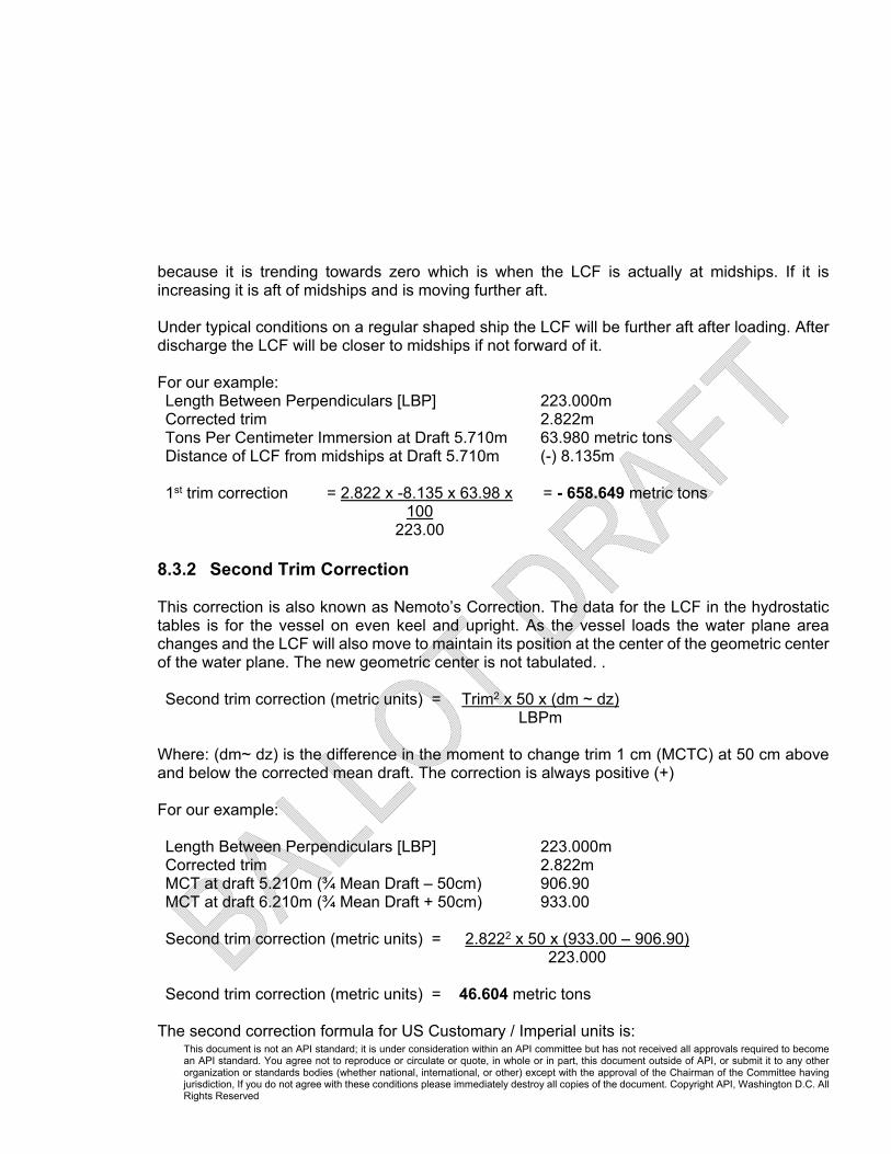
because it is trending towards zero which is when the LCF is actually at midships. If it is increasing it is aft of midships and is moving further aft. Under typical conditions on a regular shaped ship the LCF will be further aft after loading. After discharge the LCF will be closer to midships if not forward of it. For our example: Length Between Perpendiculars [LBP] 223.000mCorrected trim 2.822mTons Per Centimeter Immersion at Draft 5.710m 63.980 metric tons Distance of LCF from midships at Draft 5.710m (-) 8.135m
1st trim correction = 2.822 x -8.135 x 63.98 x
100= - 658.649 metric tons
223.00 8.3.2 Second Trim Correction This correction is also known as Nemoto’s Correction. The data for the LCF in the hydrostatic tables is for the vessel on even keel and upright. As the vessel loads the water plane area changes and the LCF will also move to maintain its position at the center of the geometric center of the water plane. The new geometric center is not tabulated. . Second trim correction (metric units) = Trim2 x 50 x (dm ~ dz) LBPm
Where: (dm~ dz) is the difference in the moment to change trim 1 cm (MCTC) at 50 cm above and below the corrected mean draft. The correction is always positive (+)
For our example: Length Between Perpendiculars [LBP] 223.000mCorrected trim 2.822mMCT at draft 5.210m (¾ Mean Draft – 50cm) 906.90MCT at draft 6.210m (¾ Mean Draft + 50cm) 933.00
Second trim correction (metric units) = 2.8222 x 50 x (933.00 – 906.90) 223.000
Second trim correction (metric units) = 46.604 metric tons
The second correction formula for US Customary / Imperial units is:
This document is not an API standard; it is under consideration within an API committee but has not received all approvals required to become an API standard. You agree not to reproduce or circulate or quote, in whole or in part, this document outside of API, or submit it to any other organization or standards bodies (whether national, international, or other) except with the approval of the Chairman of the Committee having jurisdiction, If you do not agree with these conditions please immediately destroy all copies of the document. Copyright API, Washington D.C. All Rights Reserved
Second trim correction (US Customary units) = Trim(ft)2 x 6 x (dm ~ dz) LBP(ft)
Where: (dm~ dz) is the difference in the moment to change trim 1 inch (MCTI) at 6 inches above and below the corrected mean draft. The correction is always positive (+) 8.3.3 List Correction List is normally, fairly easy for a vessel to remove and it is always preferable to do this prior to the start of the survey, rather than to use a list correction; however, in those cases where a list correction is unavoidable the correction is in metric tons is applied to the displacement of the vessel by the formula, which is always positive (+): Correction for list = 6 (TPC2 – TPC1) X (d2 – d1) Where: d2 and d1 = Midships drafts on each sideTPC1 = the TPC equivalent to the drafts d1
TPC2 = the TPC equivalent to the drafts d2
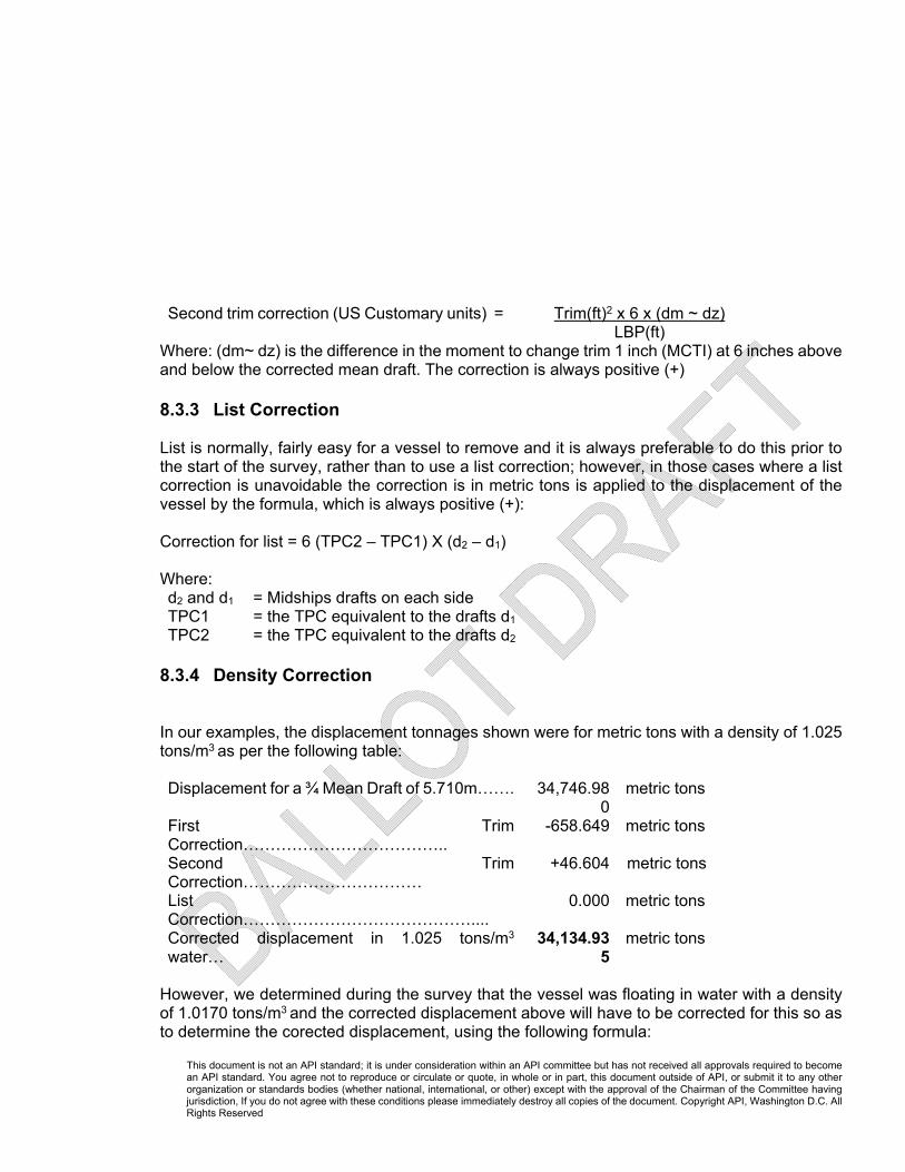
8.3.4 Density Correction In our examples, the displacement tonnages shown were for metric tons with a density of 1.025 tons/m3 as per the following table: Displacement for a ¾ Mean Draft of 5.710m……. 34,746.98
0metric tons
First Trim Correction………………………………..
-658.649 metric tons
Second Trim Correction……………………………
+46.604 metric tons
List Correction……………………………………....
0.000 metric tons
Corrected displacement in 1.025 tons/m3
water… 34,134.93
5metric tons
However, we determined during the survey that the vessel was floating in water with a density of 1.0170 tons/m3 and the corrected displacement above will have to be corrected for this so as to determine the corected displacement, using the following formula:

This document is not an API standard; it is under consideration within an API committee but has not received all approvals required to become an API standard. You agree not to reproduce or circulate or quote, in whole or in part, this document outside of API, or submit it to any other organization or standards bodies (whether national, international, or other) except with the approval of the Chairman of the Committee having jurisdiction, If you do not agree with these conditions please immediately destroy all copies of the document. Copyright API, Washington D.C. All Rights Reserved
Corrected displacement =
Corrected displacement per vessels displacement tables x density of flotation water
Density used to compile the vessels displacement tables Corrected displacement =
34,134.935 x 1.0170 = 33,868.516 metric tons
1.0250
8.4 Determination of Net Weights 8.4.1 Net (Light-ship) Weight – Initial Survey The net weight is calculated by subtracting the variable and consumable items from the corrected displacement. For our example, we have the following variable and consumables: Sea Water Ballast 18,532.130 Fresh and Grey Water 170.000 Heavy Fuel Oil 678.220 Diesel Fuel Oil 119.880 Lube Oil 20.740 TOTAL 19,520.970 metric tons Therefore, Net (light-ship) weight
= Corrected Displacement – Consumables and Variables
= 33,868.516 – 19,520.970 metric tons = 14,347.546 metric tons
8.4.2 Stated Light-ship Weight and Constant While the major consumable and variable items are measured as shown in Section 7.3, there are numerous consumable and variable items for which it is not practical to measure and these are often simply referred to as the “ship’s stores”. When the ship is built, there will be a stated light-ship quantity, specified in the stability book, which is the weight of the ship complete in all respects when empty, but with full equipment, engine spares, lubricating oils in the engine and water in the boiler. The difference between the measured net light-ship weight and the stated light-ship weight is called the constant, although this is a misnomer as the figure is not constant and a better term would be “stores variable”.

This document is not an API standard; it is under consideration within an API committee but has not received all approvals required to become an API standard. You agree not to reproduce or circulate or quote, in whole or in part, this document outside of API, or submit it to any other organization or standards bodies (whether national, international, or other) except with the approval of the Chairman of the Committee having jurisdiction, If you do not agree with these conditions please immediately destroy all copies of the document. Copyright API, Washington D.C. All Rights Reserved
The ship may have a nominal constant value, as calculated by naval architects at time of the vessel new build delivery, and while the main function of the “light” survey is to determine a measured value for the constant, comparison of the measured value to the nominal value should be evaluated. In our example: Measured light-ship Weight 14,347.546 Stated Light-ship Weight 14,164.000 Measured Constant 183.546 Nominal Constant 175.000 Difference 8.546 Metric Tons (4.9%) 8.4.3 Final Loaded or Discharged Quantity The examples shown in this section represent the initial or light-ship survey for a vessel immediately prior to loading. In order to determine the quantity loaded, a final or heavy-ship survey will be performed using the same procedures and calculations as for the initial survey, which will result in a “Net (heavy-ship) weight”. The amount of cargo loaded = Net (heavy-ship) weight - Net (light-ship) weight Cargo Loaded
= Net (heavy-ship) weight - Net (light-ship) weight
= 63,571.724 – 14,347.546 = 49,224.178 metric tons
The same procedures and calculations are used if the vessel is discharging; however, the initial survey will be for the heavy-ship condition and the final survey will be for the light-ship condition.
9 Reporting It is normal for the surveyor to issue a survey report at completion of the survey. While it is not the intent of this standard to specify a particular type of report, such a report typically includes:
● Key Meeting Report ● Initial Survey Worksheet ● Final Survey Worksheet ● Ballast / Fresh Water / Bunkers Worksheet ● Time Log and Key Data Summary ● Weight Certificate ● Inspection Checklist and General Comments

This document is not an API standard; it is under consideration within an API committee but has not received all approvals required to become an API standard. You agree not to reproduce or circulate or quote, in whole or in part, this document outside of API, or submit it to any other organization or standards bodies (whether national, international, or other) except with the approval of the Chairman of the Committee having jurisdiction, If you do not agree with these conditions please immediately destroy all copies of the document. Copyright API, Washington D.C. All Rights Reserved
9.1 Initial and Final Survey Spreadsheet This standard is issued with a companion spread sheet (informative) to assist the user. See Annex E. In order that different users using the same input data will arrive at the same output, the input discrimination levels must be consistent. 9.1.1 Discrimination Data Level
In many cases the number of decimal places that are to be used is influenced by the source of the data itself. For example, if a vessel’s capacity tables are calibrated to the nearest decimeter, than all subsequent values should be recorded accordingly. However, in those cases where there are no other limiting factors, the operator should be guided as follows by Table 1.
Table 1 – Decimal Places
Units No. of No. of Decimals Units Decimals Liters …, xxx.xxx Short tons xxx.xxx Gallons …, xxx.xxx Metric tons xxx.xxx Meters …, xxx.xxx Long tons xxx.xxx Cubic meters …, xxx.xxx Density kg/m3 xxxx.xxx Pounds …, xxx.xxx Density kg/l (metric tons/ m3) x.xxx Kilograms …, xxx.xxx Density correction coefficient x.xxx Feet …, xxx.xxx Relative density x.xxx Moment to change the draft for1cm …, xxx.xxx

This document is not an API standard; it is under consideration within an API committee but has not received all approvals required to become an API standard. You agree not to reproduce or circulate or quote, in whole or in part, this document outside of API, or submit it to any other organization or standards bodies (whether national, international, or other) except with the approval of the Chairman of the Committee having jurisdiction, If you do not agree with these conditions please immediately destroy all copies of the document. Copyright API, Washington D.C. All Rights Reserved
9.1.2 Initial Survey Worksheet

This document is not an API standard; it is under consideration within an API committee but has not received all approvals required to become an API standard. You agree not to reproduce or circulate or quote, in whole or in part, this document outside of API, or submit it to any other organization or standards bodies (whether national, international, or other) except with the approval of the Chairman of the Committee having jurisdiction, If you do not agree with these conditions please immediately destroy all copies of the document. Copyright API, Washington D.C. All Rights Reserved
9.1.3 Final Survey Worksheet

This document is not an API standard; it is under consideration within an API committee but has not received all approvals required to become an API standard. You agree not to reproduce or circulate or quote, in whole or in part, this document outside of API, or submit it to any other organization or standards bodies (whether national, international, or other) except with the approval of the Chairman of the Committee having jurisdiction, If you do not agree with these conditions please immediately destroy all copies of the document. Copyright API, Washington D.C. All Rights Reserved
9.1.4 Summary Report on Draft Survey Measurement

This document is not an API standard; it is under consideration within an API committee but has not received all approvals required to become an API standard. You agree not to reproduce or circulate or quote, in whole or in part, this document outside of API, or submit it to any other organization or standards bodies (whether national, international, or other) except with the approval of the Chairman of the Committee having jurisdiction, If you do not agree with these conditions please immediately destroy all copies of the document. Copyright API, Washington D.C. All Rights Reserved

This document is not an API standard; it is under consideration within an API committee but has not received all approvals required to become an API standard. You agree not to reproduce or circulate or quote, in whole or in part, this document outside of API, or submit it to any other organization or standards bodies (whether national, international, or other) except with the approval of the Chairman of the Committee having jurisdiction, If you do not agree with these conditions please immediately destroy all copies of the document. Copyright API, Washington D.C. All Rights Reserved
Annex A - Tools required for the survey (Informative)
The following tools are typically required in order to carry out a draft survey.
● Tools to assist reading the draft marks = tubes etc. ● Steel gauge tape with brass plumb bob ● Ballast water sampling device ● Manometer ● Stilling tubes to assist in reading the draft marks ● Calibrated Marine hydrometer and plastic cylinder/beaker. ● Paint or other waterproof marker to mark the deck. ● Water sampler and rope. ● Water finding paste. ● Field notebook/tally book for recording measurements and observations. ● Flashlight. (Intrinsically safe type is preferred). ● Rain gauge measuring in fractions of an inch. ● Personal protective equipment. ● Computer
This document is not an API standard; it is under consideration within an API committee but has not received all approvals required to become an API standard. You agree not to reproduce or circulate or quote, in whole or in part, this document outside of API, or submit it to any other organization or standards bodies (whether national, international, or other) except with the approval of the Chairman of the Committee having jurisdiction, If you do not agree with these conditions please immediately destroy all copies of the document. Copyright API, Washington D.C. All Rights Reserved
Annex B – Using a Manometer
(Informative)
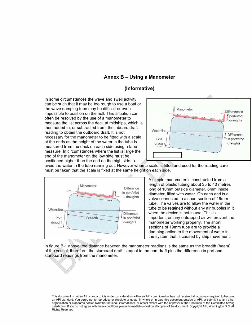
In some circumstances the wave and swell activity can be such that it may be too rough to use a boat or the wave damping tube may be difficult or even impossible to position on the hull. This situation can often be resolved by the use of a manometer to measure the list across the deck at midships, which is then added to, or subtracted from, the inboard draft reading to obtain the outboard draft. It is not necessary for the manometer to be fitted with a scale at the ends as the height of the water in the tube is measured from the deck on each side using a tape measure. In circumstances where the list is large the end of the manometer on the low side must be positioned higher than the end on the high side to avoid the water in the tube running out. However when a scale is fitted and used for the reading care must be taken that the scale is fixed at the same height on each side.
A simple manometer is constructed from a length of plastic tubing about 35 to 40 metres long of 10mm outside diameter, 6mm inside diameter, filled with water. On each end is a valve connected to a short section of 19mm tube. The valves are to allow the water in the tube to be retained without any air bubbles in it when the device is not in use. This is important, as any entrapped air will prevent the manometer working properly. The short sections of 19mm tube are to provide a damping action to the movement of water in the system that is caused by ship movement.
In figure B-1 above, the distance between the manometer readings is the same as the breadth (beam) of the vessel; therefore, the starboard draft is equal to the port draft plus the difference in port and starboard readings from the manometer.
This document is not an API standard; it is under consideration within an API committee but has not received all approvals required to become an API standard. You agree not to reproduce or circulate or quote, in whole or in part, this document outside of API, or submit it to any other organization or standards bodies (whether national, international, or other) except with the approval of the Chairman of the Committee having jurisdiction, If you do not agree with these conditions please immediately destroy all copies of the document. Copyright API, Washington D.C. All Rights Reserved
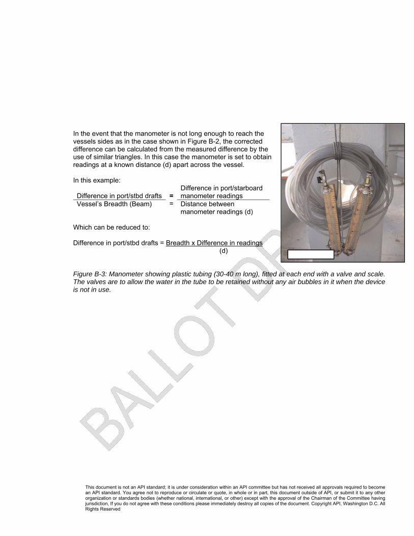
In the event that the manometer is not long enough to reach the vessels sides as in the case shown in Figure B-2, the corrected difference can be calculated from the measured difference by the use of similar triangles. In this case the manometer is set to obtain readings at a known distance (d) apart across the vessel. In this example: Difference in port/stbd drafts
==
Difference in port/starboard manometer readings
Vessel’s Breadth (Beam) Distance between manometer readings (d)
Which can be reduced to: Difference in port/stbd drafts = Breadth x Difference in readings
(d) Figure B-3: Manometer showing plastic tubing (30-40 m long), fitted at each end with a valve and scale. The valves are to allow the water in the tube to be retained without any air bubbles in it when the device is not in use.

This document is not an API standard; it is under consideration within an API committee but has not received all approvals required to become an API standard. You agree not to reproduce or circulate or quote, in whole or in part, this document outside of API, or submit it to any other organization or standards bodies (whether national, international, or other) except with the approval of the Chairman of the Committee having jurisdiction, If you do not agree with these conditions please immediately destroy all copies of the document. Copyright API, Washington D.C. All Rights Reserved
Annex C – Hydrometers (Informative)
Draft survey hydrometers These instruments are designed to measure the ‘apparent density of water’. For purposes of draft surveys: Apparent density (weight in air per unit volume) (t/m3) x Volume (m3) = Weight (t). Modern hydrometers of glass manufacture are calibrated at standard temperature, 15° C or 60° F, and measure the apparent density of the water sample in kilograms per liter in air. They are usually marked ‘for draft survey’ and ‘medium ST’ (medium surface tension) and graduated in the range 0.990 / 1.040 kg/l. These instruments are used to determine the weight in air (apparent weight) of a vessel, from which the weight of the cargo on board may be calculated. When manufactured of glass and calibrated at standard temperature, a small error results if the hydrometer is not being used at the designed standard temperature. However, it is accepted that no temperature correction is necessary, as it is compensated at survey by the change in volume of the steel vessel itself. The corrections due to the ‘coefficients of cubical expansion’ of glass and steel are very approximately the same, thus they cancel out. Older types of hydrometer used for draft surveys and manufactured from brass, or some other metal, can still be found on some vessels. These instruments should be accompanied with a table of corrections and the relevant temperature correction should always be applied. It is recommended that the use of a glass hydrometer is always preferable. The fragile glass hydrometer should be kept clean and protected. Draft survey hydrometers should not be used for load line survey purposes. The displacement and apparent weight of a vessel have a relationship, as do the relative and apparent densities of the water in which the vessel is floating. The difference between the relative density (specific gravity) as determined by relative density hydrometer and apparent density as determined from a draft survey hydrometer, is known as the ‘air buoyancy correction’, and can be accepted, at standard temperatures 15°C/15°C or 60°F/60°F, as 0.002 for marine surveys. For example, a sample of seawater checked by a load line hydrometer and showing a relative density 1.025, would show an apparent density of 1.023 kg/l in air using a draft survey hydrometer. For additional information refer to API MPMS Chapter 11—Physical Properties Data, Section 5—Density/Weight /Volume Intraconversion. All hydrometers should be calibrated regularly; typically every six to twelve months depending upon how often the hydrometer is in service.

This document is not an API standard; it is under consideration within an API committee but has not received all approvals required to become an API standard. You agree not to reproduce or circulate or quote, in whole or in part, this document outside of API, or submit it to any other organization or standards bodies (whether national, international, or other) except with the approval of the Chairman of the Committee having jurisdiction, If you do not agree with these conditions please immediately destroy all copies of the document. Copyright API, Washington D.C. All Rights Reserved
Surveyors should only use a hydrometer manufactured for the relevant type of survey being undertaken.

This document is not an API standard; it is under consideration within an API committee but has not received all approvals required to become an API standard. You agree not to reproduce or circulate or quote, in whole or in part, this document outside of API, or submit it to any other organization or standards bodies (whether national, international, or other) except with the approval of the Chairman of the Committee having jurisdiction, If you do not agree with these conditions please immediately destroy all copies of the document. Copyright API, Washington D.C. All Rights Reserved
Annex D - Salinity Refractometers
(Informative) Salinity refractometers have been used in the aquaculture and food industries for a number of years to check the salinity of water samples. A refractometer uses the fact that light deflects as it passes through different substances. When passing through water, the degree of deflection (refraction) is directly related to the quantity of mineral salts dissolved in the water. The refractive index of a substance is a measure of how far light is bent by that substance. For example, at 20°C the refractive index of distilled water is 1.333 and the refractive index of sea water (relative density 1.025, salinity 35 parts per thousand) at the same temperature is 1.339. When using a refractometer, a sample is placed on an optical prism in the sample window. As light passes through the sample, the rays are bent according to the salinity of the water casting a shadow on the scale which is visible through the eyepiece. When using a basic hand held refractometer it should be calibrated each time it is used or at least daily and the user should ensure the prism is kept clean using a soft cloth. Calibrate the unit as follows:
● Place several drops of distilled water on the prism and close the cover plate.
● If the refractometer meter reads zero, then it is properly calibrated. ● If not, rotate the calibration screw until the shadow boundary lines up with the zero mark.

This document is not an API standard; it is under consideration within an API committee but has not received all approvals required to become an API standard. You agree not to reproduce or circulate or quote, in whole or in part, this document outside of API, or submit it to any other organization or standards bodies (whether national, international, or other) except with the approval of the Chairman of the Committee having jurisdiction, If you do not agree with these conditions please immediately destroy all copies of the document. Copyright API, Washington D.C. All Rights Reserved
Annex E – Survey Template
(Informative) API 17.14.1 Ocean Going Vessel Draft Survey Spreadsheet.xls

This document is not an API standard; it is under consideration within an API committee but has not received all approvals required to become an API standard. You agree not to reproduce or circulate or quote, in whole or in part, this document outside of API, or submit it to any other organization or standards bodies (whether national, international, or other) except with the approval of the Chairman of the Committee having jurisdiction, If you do not agree with these conditions please immediately destroy all copies of the document. Copyright API, Washington D.C. All Rights Reserved
Bibliography UK P&I Club Careful to Carry – May 2008 - Measurement of bulk cargoes - Draught surveys – practice North of England P&I Association – Draught Surveys – A Guide to Good Practice - 1994 United Nations Code of Uniform Standards and Procedures for the Performance of Draught Surveys of Coal Cargoes – 3 February 1992